Loading ...
Loading ...
Loading ...
Part Number 550-142-303/1120
10
EG
/
PEG sEriEs 6
•
EGH sEriEs 5 Gas-firEd boilErs — boilEr manual
Hydrostatic pressure test
Pressure test before attaching gas piping or electrical supply.
1. Plug any necessary boiler tappings or openings.
2. Do not use gauge supplied with boiler for pressure testing.
Install gauge with appropriate range.
3. Fill boiler with water. Vent all air. Test steam boilers between
45 - 55 psi. Test water boilers at 1-1/2 times maximum work-
ing pressure.
Do not leave boiler unattended. A cold water fill
could expand and cause excessive pressure, result-
ing in severe personal injury, death or substantial
property damage.
4. Verify gauge pressure is maintained. Check for leaks. Repair
if found.
Leaks must be repaired at once. Failure to do so
can cause boiler damage, resulting in substantial
property damage.
Do not use petroleum-based sealing compounds in
boiler system. Severe damage to boiler will result,
causing substantial property damage.
5. Drain boiler and repair leaks if found.
6. Retest boiler after repairing leaks.
7. Remove plugs from any tappings that will be used for controls
and accessories. Refer to Table 4 and Figure 5.
8. On initial start-up check for leaks in the system piping.
If found, repair at once.
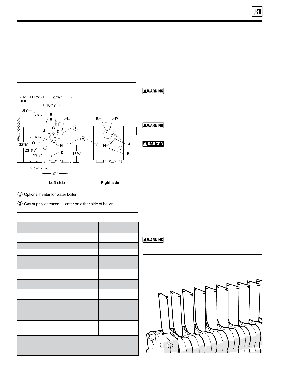
Installation of flue baffles (EG water and
EGH only)
1. Bend the two (2) tabs on the flue baffle approx. 90 degrees in
opposite directions.
2. Slide flue baffles (notch down and to the back) in between
each section.
The installer must install all flue baffles for proper
boiler operation.
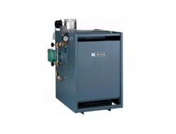
Figure 5 Boiler tappings (see Table 4)
Table 4 Control tapping (see Figure 5)
Prepare the boiler (continued)
Tapping
Size
EG, PEG & EGH
Steam Boilers
EG Water Boilers
only
C
¾”
Probe-type low water cutoff
Probe-type LWCO
(when used)
D
¾”
Drain
Drain
E
¾”
Safety valve
Safety relief valve
G
¾”
Plugged
Piping to compression
tank or
auto air vent
H
½”
Gauge glass and /or optional
low water cutoff
Combination pressure
temperature gauge
J
⅜”
Tri cock tappings
Plugged on
(Float type LWCO)
L
½”
Siphon, pressure gauge, high
limit (Probe type LWCO)
Combination pressure
temperature gauge
P
(EGH
Only)
1
Float type low water cut-off, pressure
limit control and pressure gauge;
or low water cut-off and feeder
combination; or low water cut-off and
pump control
––
S
1 ½”
¾”
(note 1)
Skim tapping
––
Limit control
Limit control
Notes:
1. Available on special request only, when tankless heater is specied.
2. Limit control and supply piping must be on the same end of the EGH
boiler.
3. When an internal type water heater is installed, use the tapping in
the heater for an additional operating control.
Figure 6a EG water & EGH - Flue baffles
Installation of optional indirect water
heater
1. For a boiler ordered with internal type indirect water heater,
remove heater opening cover plate (water boilers – round
plate on left side; steam boilers – rectangular plate on front).
2. Install heater(s) as shown on page 21. Do not over tighten
studs and nuts - damage to the gasket can occur.
Bend tabs on each plate to
keep from falling through
ue way.
Loading ...
Loading ...
Loading ...