Loading ...
Loading ...
Loading ...
Part Number 550-142-303/1120
14
EG
/
PEG sEriEs 6
•
EGH sEriEs 5 Gas-firEd boilErs — boilEr manual
General
Install the boiler jacket before connecting return piping. (Supply piping
can be connected before or after jacket installation.) Connect controls
after all piping is connected.
If installation is to comply with ASME or Canadian requirements, an ad-
ditional high temperature limit may be needed. Install control in supply
piping between boiler and isolation valve. Set second control to minimum
20 °F above set point of first control. Maximum allowable set point is 240
°F. See page 23 for wiring.
A low water cutoff device is required when boiler is installed above radia-
tion level or by certain state or local codes or insurance companies. The
boiler has a pre-installed water temperature sensor. EG water boilers are
equipped with a water temperature and low water sensor and the control
modules includes functionality for low water monitoring. An additional
external low water cutoff device may be used simultaneously if necessary.
Use backflow check valve in cold water supply if required by local codes.
Isolation valves
Isolation valves are required to enable servicing of the boiler’s temperature
sensor. Install as shown in appropriate piping diagram.
Near-boiler piping
Boiler connections
1. EG — Connect supply and return to left end.
2. Plug all unused connections.
Systems operating at or above 130°F (Return water temperature)
See Table 6 and Figure 14, page 15 (diaphragm-type or bladder-type ex-
pansion tank) or Figure 13 (closed-type expansion tank) on page 15 for
near-boiler piping for systems designed for return water at least 130 °F.
Low-temperature systems
1. See Figures 16 and 17, page 16 for near-boiler piping for low-temper-
ature or high-volume systems.
2. See Figure 15, page 15 for boilers used with refrigeration systems.
Relief valve
Install relief valve vertically in ¾” tapping on side of boiler. See the tag
attached to the relief valve for manufacturer’s instructions.
To avoid water damage or scalding due to valve operation, dis-
charge line must be connected to relief valve outlet and run to a
safe place of disposal. Terminate the discharge line to eliminate
possibility of severe burns should the valve discharge.
• Dischargelinemustbeasshortaspossibleandbethesamesize
as the valve discharge connection throughout its entire length.
• Dischargelinemustpitchdownwardfromthevalveandter-
minate at least 6” above the floor drain where any discharge
will be clearly visible.
• Thedischargelineshallterminateplain,notthreaded,with
a material serviceable for temperatures of 375 °F or greater.
• Donotpipethedischargetoanyplacewherefreezingcould
occur.
• Noshutoffvalveshallbeinstalledbetweenthereliefvalve
and boiler, or in the discharge line. Do not plug or place any
obstruction in the discharge line.
• Failuretocomplywiththeaboveguidelinescouldresultin
failure of the relief valve to operate, resulting in possibility of
severe personal injury, death or substantial property damage.
• Testtheoperationofthevalveafterllingandpressurizing
system by lifting the lever. Make sure the valve discharges
freely. If the valve fails to operate correctly, replace it with a
new relief valve.
Circulator
The circulator is not provided, but wiring is supplied
with boiler to allow you to locate it either in the return
or supply piping, as desired. See page 12 for a typical
installation. Pipe the expansion tank to the suction
side of the circulator whenever possible. Install an air
separator in the supply piping. Connect the expansion
tank to the air separator only if the separator is on the
suction side of the circulator. Always install the system
fill connection at the same point as the expansion tank
connection to the system. Figures 13 and 14, page 15
show typical near-boiler piping connections.
Expansion tank
Diaphragm-type or bladder-type tank — Figure 14,
page 15
1. Ensure expansion tank size will handle boiler and
system water volume and temperature. Tank must
be located in boiler return piping as close to boiler
as possible, before inlet side of circulator. See tank
manufacturer’s instructions for details.
2. Install an automatic air vent as shown.
Closed-type tank — Figure 13, page 15
1. Ensure expansion tank size will handle boiler and
system water volume and temperature. See tank
manufacturer’s instructions for details.
2. Connect tank to ½” NPT tapping located behind
supply outlet, using ½” NPT piping. Pitch any
horizontal piping up towards tank 1 inch per 5 feet
of piping.
Undersized expansion tanks cause system
water to be lost from relief valve and
makeup water to be added through fill
valve. Eventual section failure can result.
Water piping — multiple zone systems
Install system piping using either circulator zoning or
zone valve zoning. Install expansion tank on suction side
of system circulator. Always connect fill line only at the
expansion tank — never at another point in the system.
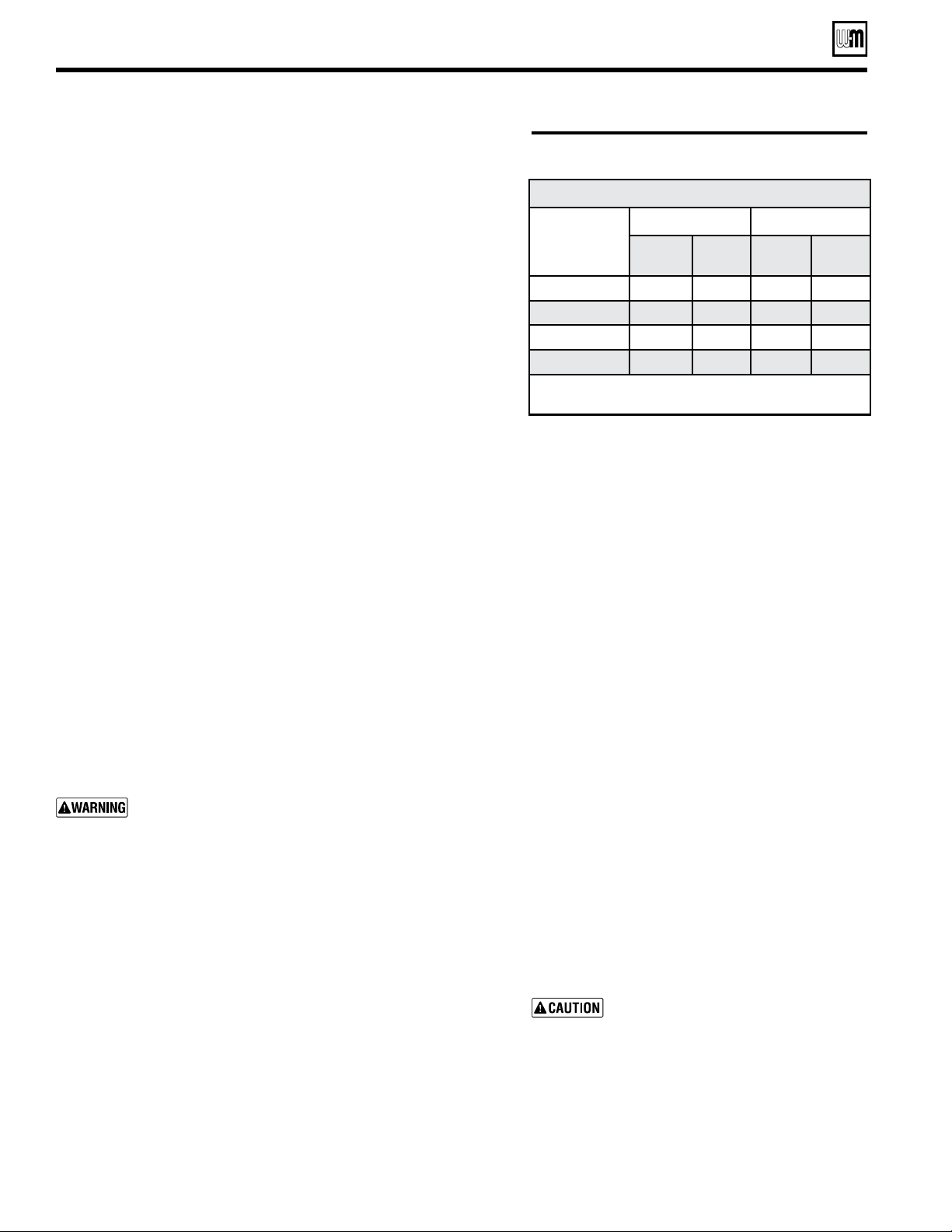
Table 6 Minimum recommended pipe sizes
Connect piping – water boilers – EG only
Minimum Recommended Pipe Sizes (for 20°F rise)
Boiler
model
Forced-ow systems Gravity-ow systems
Supply
“A”
Return
“B”
Supply
“A”
Return
“B”
EG-30, 35 1” 1” 1 ½” 1 ½”
EG-40, 45, 50 1 ¼” 1 ¼” 2” 2”
EG-55, 65 1 ½” 1 ½” 2 ½” 2 ½”
EG-75 2” 2” 2 ½” 2 ½”
Note: * All supply and return pipe sizes are based upon a 2°
F temperature rise through the boiler.
Loading ...
Loading ...
Loading ...