Loading ...
Loading ...
Loading ...
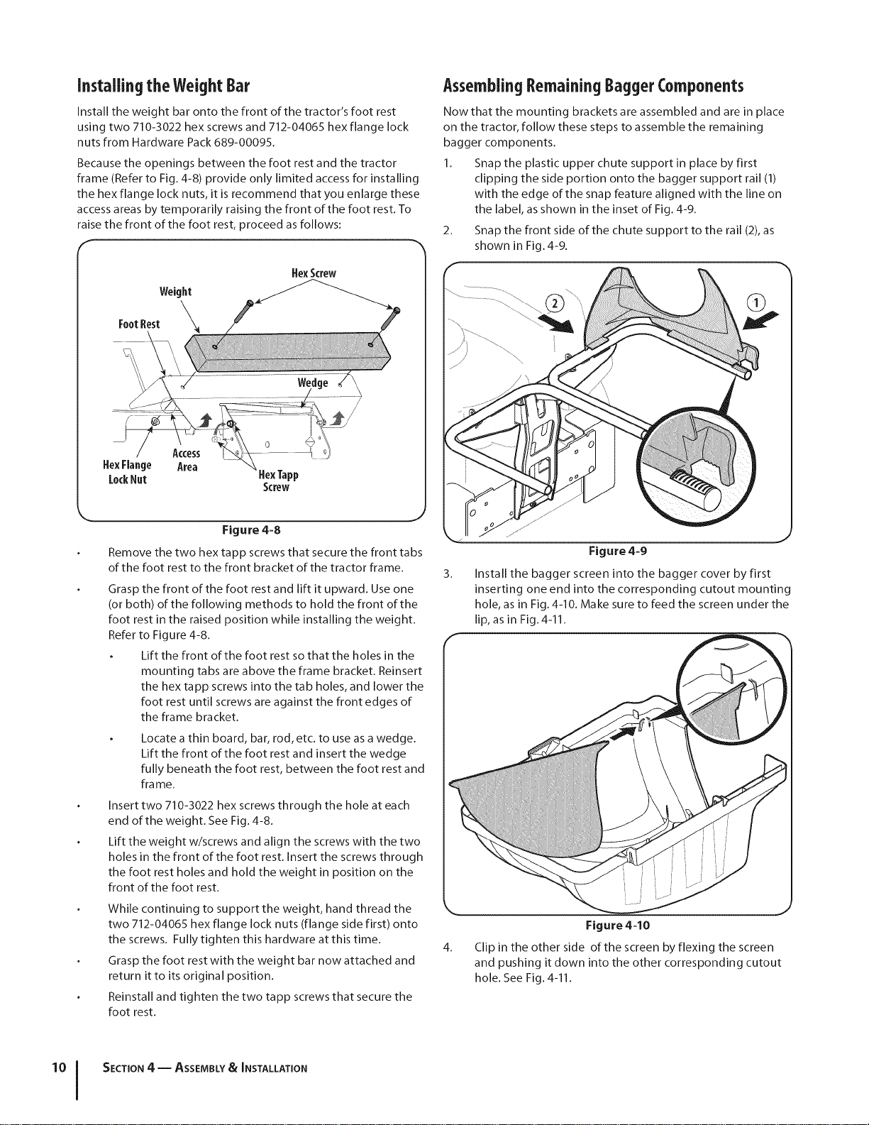
Installingthe WeightBar
Install the weight bar onto the front of the tractor's foot rest
using two 710-3022 hex screws and 712-04065 hex flange lock
nuts from Hardware Pack 689-00095.
Because the openings between the foot rest and the tractor
frame (Refer to Fig. 4-8) provide only limited access for installing
the hex flange lock nuts, it is recommend that you enlarge these
access areas by temporarily raising the front of the foot rest. To
raise the front of the foot rest, proceed as follows:
HexScrew
HexTapp
Screw
Figure 4=8
Remove the two hex tapp screws that secure the front tabs
of the foot rest to the front bracket of the tractor frame.
Grasp the front of the foot rest and lift it upward. Use one
(or both) of the following methods to hold the front of the
foot rest in the raised position while installing the weight.
Refer to Figure 4-8.
Lift the front of the foot rest so that the holes in the
mounting tabs are above the frame bracket. Reinsert
the hex tapp screws into the tab holes, and lower the
foot rest until screws are against the front edges of
the frame bracket.
Locate a thin board, bar, rod, etc. to use as a wedge.
Lift the front of the foot rest and insert the wedge
fully beneath the foot rest, between the foot rest and
fra me.
Insert two 710-3022 hex screws through the hole at each
end of the weight. See Fig. 4-8.
Lift the weight w/screws and align the screws with the two
holes in the front of the foot rest. Insert the screws through
the foot rest holes and hold the weight in position on the
front of the foot rest.
While continuing to support the weight, hand thread the
two 712-04065 hex flange lock nuts (flange side first) onto
the screws. Fully tighten this hardware at this time.
Grasp the foot rest with the weight bar now attached and
return it to its original position.
Reinstall and tighten the two tapp screws that secure the
foot rest.
AssemblingRemainingBaggerComponents
Now that the mounting brackets are assembled and are in place
on the tractor, follow these steps to assemble the remaining
bagger components.
1. Snap the plastic upper chute support in place by first
clipping the side portion onto the bagger support rail (1)
with the edge of the snap feature aligned with the line on
the label, as shown in the inset of Fig. 4-9.
2. Snap the front side of the chute support to the rail (2), as
shown in Fig. 4-9.
3.
Figure 4-9
Install the bagger screen into the bagger cover by first
inserting one end into the corresponding cutout mounting
hole, as in Fig. 4-10. Make sure to feed the screen under the
lip, as in Fig. 4-11.
4.
Figure 4=10
Clip in the other side of the screen by flexing the screen
and pushing it down into the other corresponding cutout
hole. See Fig. 4-11.
'°1
SECTION 4 -- ASSEMBLY& INSTALLATION
Loading ...
Loading ...
Loading ...