Loading ...
Loading ...
Loading ...
8
NEVER LEAVE HEATER UNATTENDED WHILE BURNING
OR WHILE CONNECTED TO A POWER SOURCE
© 2021 Pinnacle Climate Technologies, Inc. Kerosene Forced Air Heater User’s Manual
MAINTENANCE
Service:
DO NOT TAMPER WITH THE UNIT. HAVE
A COMPETENT SERVICEMAN MAKE ANY
NECESSARY ADJUSTMENT OR REPAIRS.
Use only original equipment parts. The use of
alternate or third party components can cause unsafe
operating conditions and will void your warranty.
We suggest following a maintenance schedule as follows:
FUEL / FUEL TANK:
Flush tank every 200 hours of operation or as needed.
DO NOT flush with water; use fresh K-1 kerosene only.
AIR FILTERS:
The air intake filter should be replaced or washed with
soap and water and dried thoroughly every 500 hours
of operation or less depending on conditions.
The output and lint filters should be replaced every
500 hours of operation or less depending on
conditions. (See Figure 3)
NOTE: Use of diesel fuel may require additional
maintenance
FAN BLADES:
Blades should be cleaned at least once per
heating season, depending on conditions.
Remove all accumulated dust and dirt with a
damp cloth, taking care not to bend any of the
fan blades. Be sure the blades are dry before
re-starting the heater.
FUEL FILTER:
The fuel filter should be cleaned at least twice
per heating season. Clean the filter by rinsing
it in clean K-1 Kerosene. Contaminated fuel
could make cleaning the fuel filter necessary
immediately.
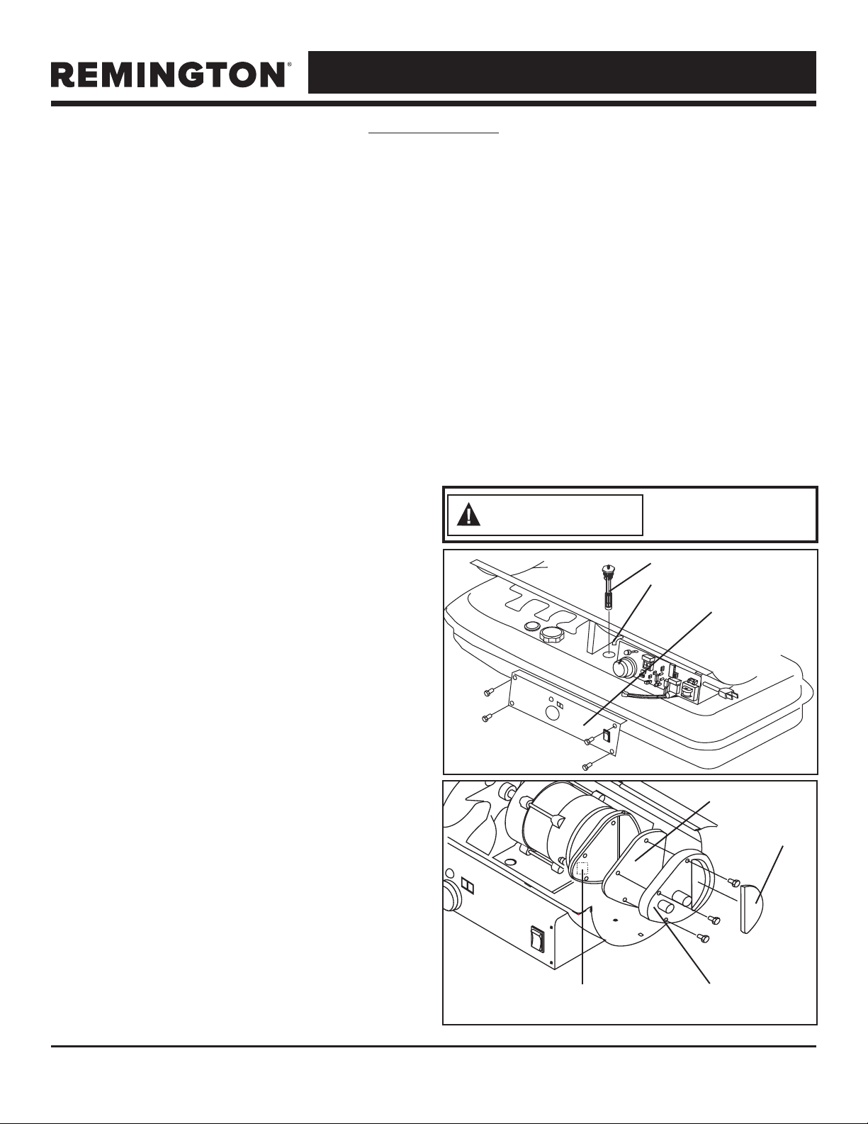
NOTE: To remove the filter from models 45 -
80T-KFA turn filter 90º clockwise. To remove the
filter from models 140T - 215T-KFA turn filter
90º counter-clockwise. See Figure 2.
THERMISTER PLACEMENT:
Ensure the thermister wire is in the proper place.
The wire should be lying on the bottom shell
inside the heater with the plastic end placed
under the motor support/motor and away from
fan blade.
ROTOR:
The rotor with carbon vanes should be evaluated
every heating season. The rotor is behind the air
filters. The vanes should be inspected for damage
or wear. The rotor should be inspected for
damage, chips, wear, cracks.
Check rotor gap: Remove the rear cover. Loosen
the two pump ring screws. Lift the pump ring
upwards. Insert a 0.1 mm feeler gauge and
apply slight downward pressure, enough to offer
resistance when attempting to remove gauge.
Hand-tighten the two pump ring screws. Re-install
the End Pump Cover and the plastic End Filter
Cover. Start the heater and adjust to the proper
pump pressure.
Air Output Filter
Intake Filter
Lint Filter End Filter
Figure 3
Never service
heater while it is
plugged in or hot!
WARNING
Figure 2
Fuel Filter
Fuel Line
Side Cover
Loading ...
Loading ...
Loading ...