Loading ...
Loading ...
Loading ...
I
_ Before inspecting, cleaning or servicing the machine, shut off engine, wait for all moving parts to
come to a stop, disconnect spark plug wire and move wire away from spark plug. Remove key on I
electric start models. I
Failure to follow these instructionscanresult in serious personal injury or propertydamage. I
CHAN61NGTRIMMER LINES
Whentrimmer lineswear, ittakes longer
to complete mowing and trimming pro-
jects. A good rule of thumb isto change
the lineswhen they reachhalftheir orig-
inal length.
Usethe extra-heavyduty (.155"diameter)
linewhen cutting thick, tough growth.
Usethinner (.130" diameter) line for less
demandingconditions and for usenear
trees or shrubs to help prevent girdling
(cutting of bark).
ToChange Trimmer Lines:
1. Stopengine,allow all partsto stop
moving and then disconnect the spark
plug wire. Removethe ignition key on
electric start models= DONOTtouchthe
metalwear cupon the bottom of the
spindle head--it may behot.
NOTE:Thetwo line holderson the
trimmer head are permanentlysecured.
Donot attempt to remove the line
holders.
2. If necessary,you may tip the unit
backslightly when changing lines. How-
ever, do not tip the unit all the way back
as motor oil may flow to the exhaustarea
and the enginemay smokefor several
secondswhen started.
3. Threedifferent line installation pat-
terns areavailable,as shown in Figures
5-10, 5-11 and 5-12.
4, Feedthe line through the loops of the
line holder as shown.
• An equal amount of lineshould project
out from eachsideof the line holder,
creating an overall 22"wide cutting
swath.
• Youmay offsetboth trimmer lines
somewhat to increasethecutting swath
up to 25" wide. However, DONOT
offset the line so that the overall cutting
swath is greaterthan 25". SeeWarning
statement at right.
Offsettingthe trimmer lines causesthe lines to rotate faster than when they project
an equal length on each side. This increasesthe chanceof loosematerials being
dislodgedand propelledat highspeeds.
Failure of the operatortowear safetygogglesand appropriateclothingand to keep
bystandersawaycanresultin severepersonalinjuryor propertydamage.
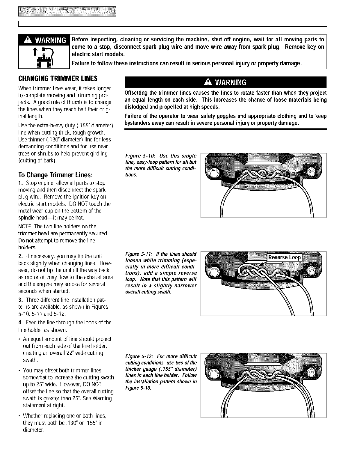
Figure 5-10: Use this single
line, easy-loop pattern fora# but
the more difficult cutting condi-
tions.
Figure 5-11: ff the lines should
loosen while trimming (espe.
cially in more difficult condi-
tions), add a simple reverse
loop. Note that this pattern will
result in a slightly narrower
overall cuttingswath.
Figure 5-12: For more difficult
cuttingconditions,use twoofthe
thicker gauge (. 155" diameter)
lines in each line holder. Follow
the installation pattern shownin
Figure5=10.
• Whetherreplacing one or both lines,
they must both be .130"or .155"in
diameter.
Loading ...
Loading ...
Loading ...