
0 TRtIII BILT
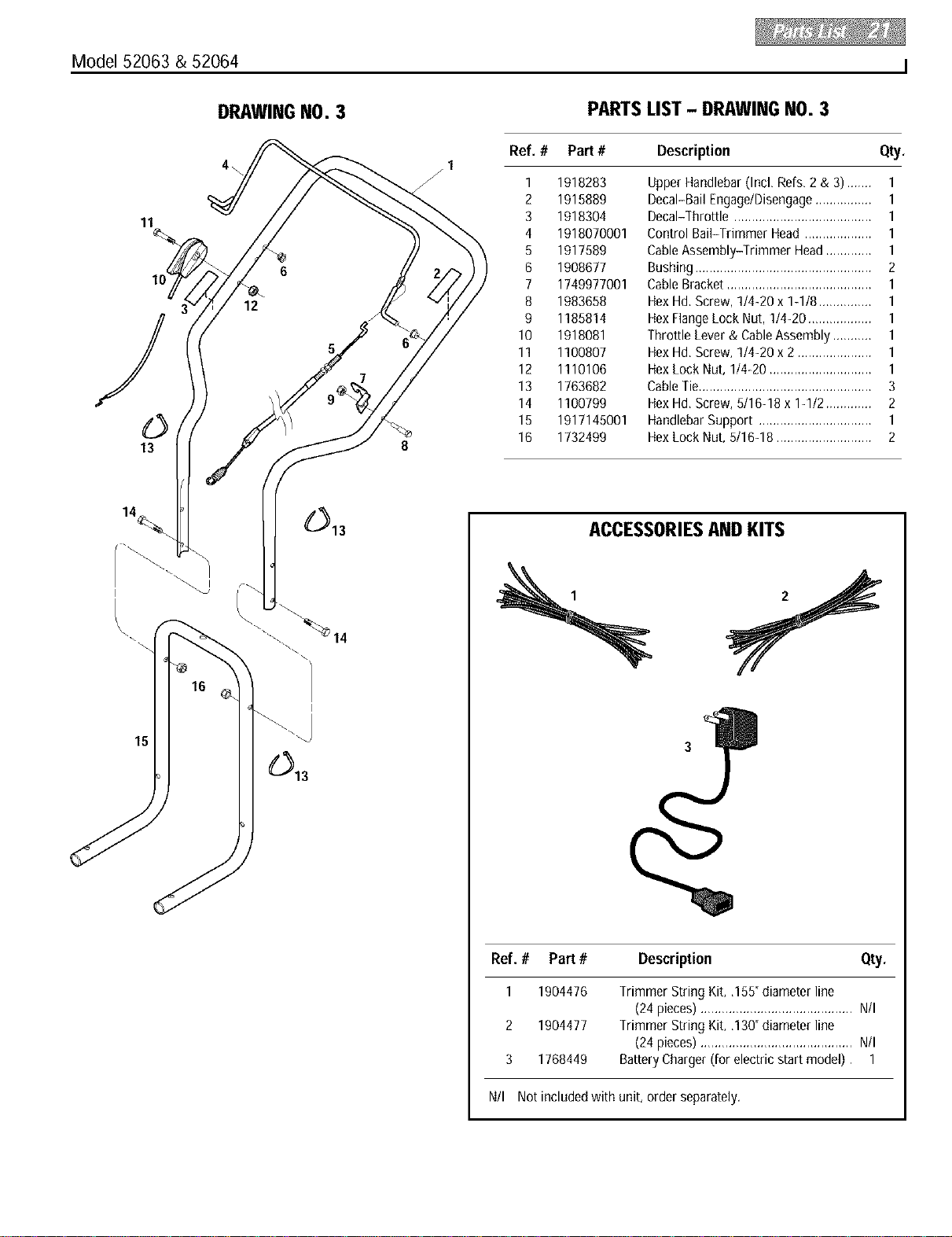
Model
52063- 5HPRecoilStart
52064- 6HPElectricStart
OWNER'SMANUAL
Trimmer/Mower
• Safety
• Assembly
• FeaturesandControls
• Operation
• Maintenance
• Parts List
(ElectricStart Model Shown)
GARDEN WAYINCORPORATED
Dear Owner:
You now own one of thefinest trimmer/mowers available.It
was designedto easilyhandle a wide varietyof trimming,
mowing andclearing chores. You will find the machine to
bean invaluabletool in caring for your property.
Pleasecarefully read this Manual. Ittells you how to safely
and easily assemble,operateandmaintain your machine.
Besure thatyou and any other operators carefully follow
therecommended safetypractices at afttimes. Failureto
do so could result in personal injury or property damage.
Of course, if you should everhaveanyproblems or ques-
tions, pleasecontact your local authorizedservicedealer or
call the Factory (seeback cover).
Wewant to besure that you are completely satisfiedat all
times.
See Back Cover for
Customer Service information
Safety Alert Symbol
This is a safety alert symbol, It is used in this
manual and on the unit to alert you to potential
hazards, When you see this symbol, read and
obey the messagethat follows it, Failureto obey
safety messagescould result in personal injury or
property damage,
WARNING
The engine exhaust from this product contains
chemicals known to the State of California to cause
cancer, birth defects or other reproductive harm.
Table of Contents
SECTION1: SAFETY........................................... 1
GeneralOperation......................................................1
Slope Operation.........................................................2
Children......................................................................2
Service.......................................................................2
SafetyDecals.............................................................3
SECTION2: ASSEMBLY....................................... 4
Inspection After Delivery............................................4
Step 1:Unpacking Unit ..............................................4
Step2: Install Handlebars..........................................4
Step 3:AttachThrottle Control Lever.........................5
Step4: Add Motor Oil.................................................5
Step5: CheckTrimmer HeadHardware.....................5
Step6: Connectand ChargeBattery...........................6
SECTION3: FEATURESAND CONTROLS................... 7
SECTION4: OPERATION...................................... 8
Pre-Start Checklist.....................................................8
Fill FuelTank..............................................................8
Adjust HandlebarHeight ............................................8
Adjust Line Cutting Height .........................................8
UseCorrect DiameterTrimmer Line...........................9
How to UsetheTrimmer HeadControl Bail................9
Operatingthe Machine...............................................9
Additional OperatingTips and Techniques...............10
Trimming/Cutting Quick ReferenceChart.................10
SECTION5: MAINTENANCE................................. 11
RequiredMaintenanceSchedule..............................11
Adjusting Trimmer HeadEngagement......................11
Removingand ReplacingtheTrimmer Head............12
Inspecting/Replacingthe Drive Belt..........................12
Cleaningand Debris Removal..................................14
Cleaningthe Engine .................................................14
Lubrication ...............................................................14
Compact Storage.....................................................14
GeneralEngineMaintenance....................................14
EngineOil Service....................................................14
Air CleanerService...................................................14
SparkPlug Service...................................................14
SparkArrester ScreenService..................................14
Carburetor/GovernorAdjustments ...........................14
Throttle Control Adjustment .....................................15
Off-SeasonStorage..................................................15
BatteryRechargingtReplacement.............................15
ChangingTrimming Lines........................................16
Troubleshooting.......................................................17
PARTSLIST ................................................... 18
ACCESSORIES& KITS....................................... 21
CUSTOMERSERVICEINFORMATION........... BackCover
Safety
SPARK ARRESTER WARNING TO RESIDENTS OF
CALIFORNIAANDSEVERALOTHERSTATES
Under California law, and under the laws of several
other states, you are not permitted to operate an
internalcombustion engine using hydrocarbon fuels on
any forest, brush, hay, grain, or grass covered land; or
land covered by any flammable agricultural crop
without an engine spark arrester in continuous effective
working order.
Theengine on the unit is an internal combustion engine
which burns gasoline, a hydrocarbon fuel, and must be
equipped with a spark arrester muffler in continuous
effective working order. The spark arrester must be
attached to the engine exhaust system in such a
manner that flames or heat from the system will not
ignite flammable material. Failure of the owner/oper-
ator of the unit to comply with this regulation is a mis-
demeanor under California law (and other states) and
may also be a violation of other state and/or federal
regulations, laws, ordinances or codes. Contact your
localfire marshal or forest servicefor specific informa-
tion aboutwhich regulations applyin your area.
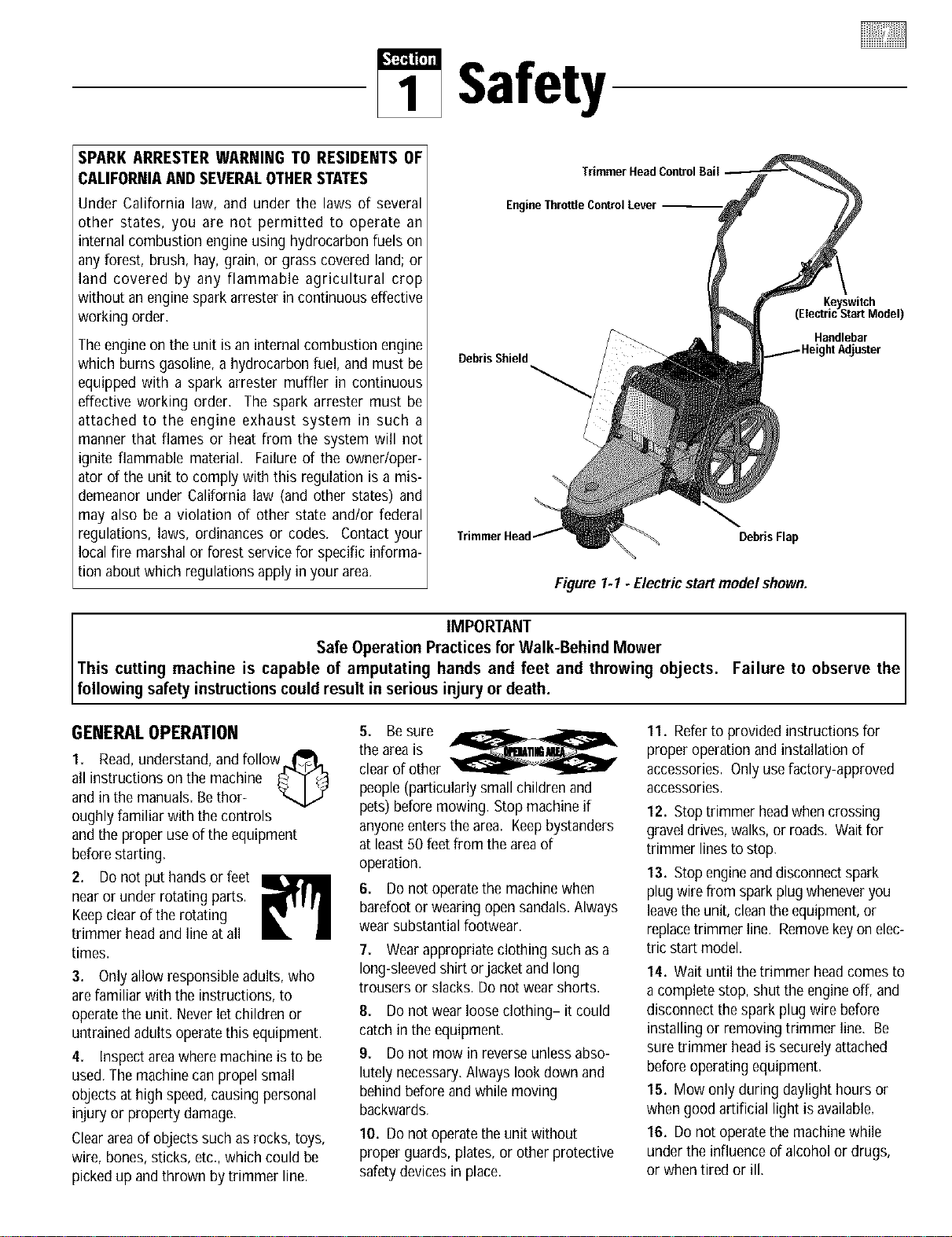
EngineThrottle ControlLever
Debris Shield
DebrisFlap
Figure 1-1 - Electric start model shown.
Keyswitch
(ElectricStart Model)
Handlebar
IMPORTANT the
Safe Operation Practices for Walk-Behind Mower
This cutting machine is capable of amputating hands and feet and throwing objects. Failure to observe
follow ng safety nstruct ons could result n ser ous njury or death.
GENERALOPERATION
1. Read,understand,and follow_,_
all instructionsonthe machine _ _
and in the manuals.Bethor-
oughly familiar with the controls
and the proper useof the equipment
beforestarting.
2, Do not put handsor feet
nearor under rotating parts.
Keepclearof the rotating
trimmer head and line at all
times.
3. Onlyallow responsible adults, who
are familiar with the instructions, to
operatethe unit. Neverlet children or
untrainedadults operatethis equipment.
4. Inspect areawhere machine isto be
used.Themachine canpropel small
objects at high speed,causing personal
injury or property damage.
Clearareaof objects such as rocks, toys,
wire, bones, sticks, etc.,which could be
pickedup andthrown by trimmer line.
5. Besure ,_-,,_rb._ _
the areais
clearof other
people (particularlysmall children and
pets) beforemowing. Stopmachine if
anyoneenters thearea. Keepbystanders
at least 50 feet from the areaof
operation.
6. Donot operatethe machine when
barefoot or wearing open sandals.Always
wear substantialfootwear.
7. Wearappropriate clothing such as a
long-sleevedshirt or jacketand long
trousers or slacks. Donot wear shorts.
8. Donot wear looseclothing- it could
catch in the equipment.
9. Donot mow inreverse unlessabso-
lutely necessary.Always lookdown and
behind before and while moving
backwards.
10, Donot operatetheunit without
proper guards, plates,or other protective
safety devicesin place.
11. Referto provided instructions for
proper operation and installation of
accessories. Only usefactory-approved
accessories.
12. Stoptrimmer headwhencrossing
graveldrives,walks, or roads. Waitfor
trimmer linesto stop.
13. Stopengineand disconnectspark
plug wirefrom sparkplug wheneveryou
leavetheunit, cleantheequipment,or
replacetrimmer line. Removekeyon elec-
tric startmodel.
14. Wait until the trimmer headcomes to
a completestop, shut the engine off, and
disconnect the spark plug wire before
installing or removing trimmer line. Be
suretrimmer headis securely attached
beforeoperating equipment.
15. Mow only during daylight hours or
whengood artificial light is available.
16. Donot operatethe machinewhile
under the influence of alcohol or drugs,
or when tired or ill.

17.Ifusingunitinwetconditions,exer-
ciseextremecaretopreventlossof
footing.Wearfootwearthatwillimprove
traction.Avoidslopingground.Holdthe
handlebarswithtwohandsandwalk;
neverrun.
18. Releasethe Trimmer HeadControl
Bailbeforestarting the engine.
19. If the unit starts to vibrate abnor-
mally,stop the engineanddisconnect the
spark plug wire. Checkimmediatelyfor
the cause.Vibration is generallya
warning of trouble.
20. Alwayswear approvedsafety gog-
gles or safetyglasseswith side shields
when operatingequipment. Theuseof
any poweredmachine canresult infor-
eign objects being thrown byhigh-speed
rotating parts which cancausepersonal
injury or property damage. Stayaway
from glass and other easilythrown or
breakableobjects.
21. Wearwork glovesand sturdy
footwearwhen usingthis equipment.
Leatherwork shoes or short boots are
ideal.They protect anklesand shins from
rocks, pebbles,splinters, etc.
22. It is advisableto wear protective
headgearto preventthe possibility of
beinghit by small flying particles, etc.
23. Beforeeachuse, inspectthe Throttle
Control Leverand cable. Makesurethe
cable isfree andthe leverfunctions
properly.
24. Watch for traffic when near or when
crossing roadways.
25. Neverattempt to carry children or
other passengerson the equipment.They
could fall off and beseriously injured,or
they could interferewith safeoperation of
the equipment.
26. The machineis equipped with a
plasticdebris shield in front of the engine
and a rubber debris flap under theframe.
They must be in placeandworking prop-
erly. Never remove or cause thedebris
shield or debris flapto ceaseworking. If
either of these parts is missing or not
working properly, do not usethe equip-
ment until this situation is corrected.
27. Beawareof wherethe machine is
discharging materialsand do not point
the discharge atanyone.
28. Never run the engine in an enclosed
area. Engineexhaustcontains carbon
monoxide, adeadly gasthat is odorless,
colorless andtasteless. Alwaysrun the
engine outdoors where there isadequate
ventilation.
29. Slow down beforeturning.
30. Shut offenginewhen not trimming
or mowing.
31. Use extra carewhen loading or
unloading machine into a trailer ortruck.
32. Usethis equipmentfor its intended
purpose only.
33. Always makesurethe handlebarsare
tight and comfortably positioned.
Theyshould never be in an awkward
position for the operator.
SLOPEOPERATION
Slopesare a major factor relatedto loss
of control and tip-over accidents which
canresult in severeinjury or death. All
slopes require extra caution. If you can
not back up the slope or you feel uneasy
on a slope,do not mow it.
Do:
Mow acrossthe face _h_b,_'
of slopes; neverup
and down. Exercise
extremecaution when changingdirec-
tion on slopes.Avoid slopes greater
than 150.
Removeobjectssuch asrocks, tree
limbs, etc,
Uneventerrain could overturn the
machine. Watchfor holes, ruts, or
bumps. Tallgrass canhide obstacles.
Use slow speed.
Use extra carewith grass catchersor
other attachments. Thesecan change
the stability of the machine. Keepall
movement on the slopes slow and
gradual.
Avoid starting or stopping on a slope.
Do Not:
Donot mow neardrop-off& ditches,or
embankments.You could losefooting
or balance.
Donotmow onvery steepslopes.
Donot mow on wet grass. Slippery
footing can behazardous.
CHILDREN
Tragic accidents can occur if the operator
is not alert to the presence of children,
Children are often attracted to the
machine and the mowing activity. Never
assume that children will remain where
you last saw them,
1, Keep children out of the mowing area
and under the watchful care of a respon-
sible adult,
2. Bealertandturnmachineoff if children
enterthe area.
3. Beforeand while moving backwards,
look behind and down for small children.
4. Neverallow children to operatethe
machine.
5. Use extra carenearblind corners,
shrubs, trees,or other objects that may
obscurevision.
6. Nevercarry children, evenwith the
trimmer headstopped. Children mayfall
off andbe seriously injured or interfere
with safe machineoperation.
7. Donot allow children nearby if you
areworking.
SERVICE
1. Useextra care in handling gasoline
and other fuels.They areflammable and
their vapors are explosive. To help pre-
vent a fire or explosion:
a) Use only an approvedcontainer.
b) Never removegas capor addfuel
whenthe engineis running. Let
enginecoolbeforerefueling.Donot
smoke.
c)
d)
e)
0
g)
Never refuelthe machine indoors,
Eillthe fuel tank outdoors andwith
extremecare.
Never store the machineor fuel
container inside wherethere isan
open flame, such asa water heater,
etc.
Replacecapson thefuel tank and
fuel container and cleanup spilled
fuel before starting engine.Move
machine awayfrom anygasoline
fumes before starting the engine.
Keepmatches, smoking materials,
open flames, and sparks awayfrom
the fuel tank and fuel container.
Leave1t2"air spaceatthe top of
the fuel tank to allow for fuel
expansion.

2. Neverrun the engine inside a closed
area.
3. Neverclean,or makeadjustmentsor
repairswith the enginerunning. Discon-
nect the spark plug wire and keepthe
wire awayfrom the plug to preventacci-
dentalstarting. Removekeyon electric
start models.
4. Keepall nuts and bolts tight, espe-
cially the trimmer head attachmentbolts,
and keepequipment in good condition.
Checkmounting hardwareon trimmer
headevery time you changetrimmer line
and prior to each use.
5. Nevertamper with safety devices.
Checktheir proper operation regularly.
6. To reducefire hazard,keep mower
freeof grass, leavesor other debris
build-up. Cleanup oil or fuel spills. Let
machine cool beforestoring.
7. After striking an object, stop the
engineand disconnect the spark plug
wire. Inspect the machineand repair, if
necessary,beforerestarting.
8. Nevermakeadjustments or repairs
while engine is running.
9. Componentssubjectto wear,
damageanddeterioration could expose
moving parts or allow objects to be
thrown. Frequentlycheckcomponents
and replacewith factory recommended
parts, when necessary. Regularly inspect
the trimmer headand debris shield.
Make surethey are not bent, damaged,or
loose.
10. Onlyuseeighteen-inch long.130"or
.155"diametertrimmer line. Neveruse
other lengths,diametersor materialas
trimmer line.
11. Trimmer line movesat high speed
and cancut. Alwaysstop the engineand
let all moving parts stop beforereplacing
the trimmer lines. Letthe engine cool.
12. Donot changethe engine governor
setting or overspeedthe engine. The
governor controls maximum safeoper-
ating speedand protects the engine and
all moving parts from damagecausedby
overspeed. Authorized serviceshall be
sought if a problem exists.
13. Donot touch engine parts which may
be hot from operation. Allow parts to
cool completely before inspecting,
cleaningor repairingthe unit.
14. Maintain or replacesafetyand
instructional decals. Referto the Parts
List for replacementdecal information.
15. Useonly original-equipment replace-
ment parts. Parts manufactured by
others could present safety hazardsand
affect performance eventhough they may
fit on this machine.
16. Remember- the end of the seasonis
a good time to inspectequipment prior to
storage.
17. To guard againstengine overheating,
alwayskeepthe engine debrisguard
mountedand clean.
18. Forunits equippedwith electric start:
a) Batteriesproduceexplosive gases.
Keepsparks, flame,cigarettes,
etc., away.Ventilateareawhen
charging battery. Do not charge
battery in an airtight space.
b) Donot usea battery chargerother
thanthe one provided with the
unit.
c)
d)
e)
Thebattery containstoxic mate-
rials. Donot damagethe battery
case.If the caseis broken or dam-
aged,avoidcontact with the bat-
tery contents.
Properly dispose of a damagedor
worn out battery. Checkwith local
authorities for proper disposal
methods.
Donot short circuit the battery.
Severeburns and fire canresult.
SAFETY DECALS
Foryour safetyand the safety of others,
various safetyand operational decalsare
locatedon your unit (seebelow).
At front of deck
Keepthe decalscleanand legible at all
times. Contactyour localservice dealeror
the factory for replacements if anydecals
are damagedor missing.
Referto the Parts List in this manualfor
decallocations, part numbers and
ordering instructions.
On left On right
handlebar handlebar
Onengine,abovemuffler
Assembly
To prevent personal injury or property
damage, do not attempt to start the
engine until all assembly steps are
completeand you have read and under-
standall of thesafety and the operating
instructionsin thisManual.
INTRODUCTION
Carefullyfollow theseassembly stepsto
correctly prepareyour machinefor use.
It is recommendedthat you readthis
Sectionin its entirety beforebeginning
assembly,
INSPECTIONAFTER DELIVERY
Inspectyour machine immediately after it
has beendelivered. Make surethat nei-
ther the carton nor the contents have
beendamaged.
If you find or suspect any damage,con-
tact the carrier (trucking company) right
away. Inform them of the specific
damageandthat you wish to file a claim.
To protect your rights, be sureto put this
in writing to thecarrier within 15 days
after your machine arrives. Pleaselet us
know if you needassistancewith this
matter.
IMPORTANT:Theengine is shipped
without motor oil in its crankcase.Motor
oil must beaddedto the engine before
starting.
NOTE:LEFTand RIGHTsides of unit are
asviewed from operator's position
behindthe handlebars.
ASSEMBLY STEPS
Tools/SuppliesNeeded:
• (1) Utility Knifeor Scissors
• (2) 1/2" (or adjustable)Wrenches
• (2) 7/16" Wrenches(one with a boxed
end)
• Motor Oil (seeengine manualfor oil
specifications and quantity required)
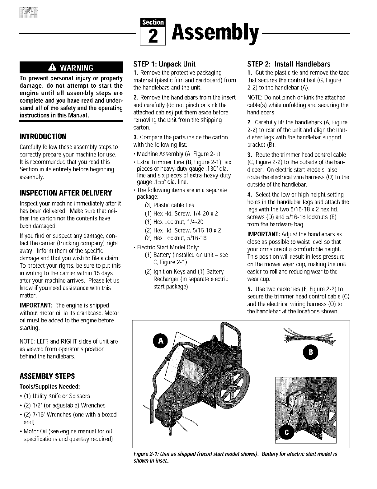
STEP 1: Unpack Unit
1. Removethe protective packaging
material (plastic film and cardboard) from
the handlebarsand the unit.
2. Removethe handlebarsfrom the insert
and carefully (do not pinch or kink the
attachedcables) putthem aside before
removing the unit from the shipping
carton.
3. Comparethe parts insidethe carton
with the following list:
• MachineAssembly (A, Figure2-1)
• ExtraTrimmer Line (B, Figure2-1): six
piecesof heavy-duty gauge .130"dia.
line and six piecesof extra-heavy-duty
gauge .155"dia. line.
•Thefollowing items are in a separate
package:
(3) Plastic cableties
(1) Hex Hd. Screw,1t4-20 x 2
(1) Hex Locknut, 1/4-20
(2) Hex Hd. Screw,5/16-18 x 2
(2) Hex Locknut, 5/16-18
• ElectricStart Model Only:
(1) Battery (installed on unit - see
C, Figure2-1)
(2) Ignition Keysand(1) Battery
Recharger(in separateelectric
start package)
STEP2: Install Handlebars
1. Cutthe plastictie and remove the tape
that securesthe control bail (G,Figure
2-2) to the handlebar (A).
NOTE:Do not pinch or kink the attached
cable(s)while unfolding and securing the
handlebars.
2. Carefullylift the handlebars(A, Figure
2-2) to rear of the unit and align the han-
dlebar legswith the handlebarsupport
bracket(B).
3. Routethe trimmer headcontrol cable
(C, Figure2-2) to theoutside of the han-
dlebar. On electricstart models,also
routethe electricalwire harness(O) to the
outside ofthe handlebar.
4. Selectthe low or high height setting
holesin the handlebarlegs andattachthe
legswith the two 5/16-18 x 2 hex hd.
screws (D) and 5/16-18 Iocknuts (E)
from the hardwarebag.
IMPORTANT:Adjustthe handlebarsas
close aspossible to waist levelso that
your arms are at a comfortable height.
This position will result in less pressure
on the mower wear cup, makingthe unit
easierto roll and reducingwearto the
wearcup.
5. Usetwo cableties (F, Figure2-2) to
securethe trimmer headcontrol cable (C)
andthe electricalwiring harness (O)to
the handlebar atthe locations shown.
O
Figure2*1: Unitas shipped (recoil start modelshown). Batteryforelectric start modelis
shownin inset.
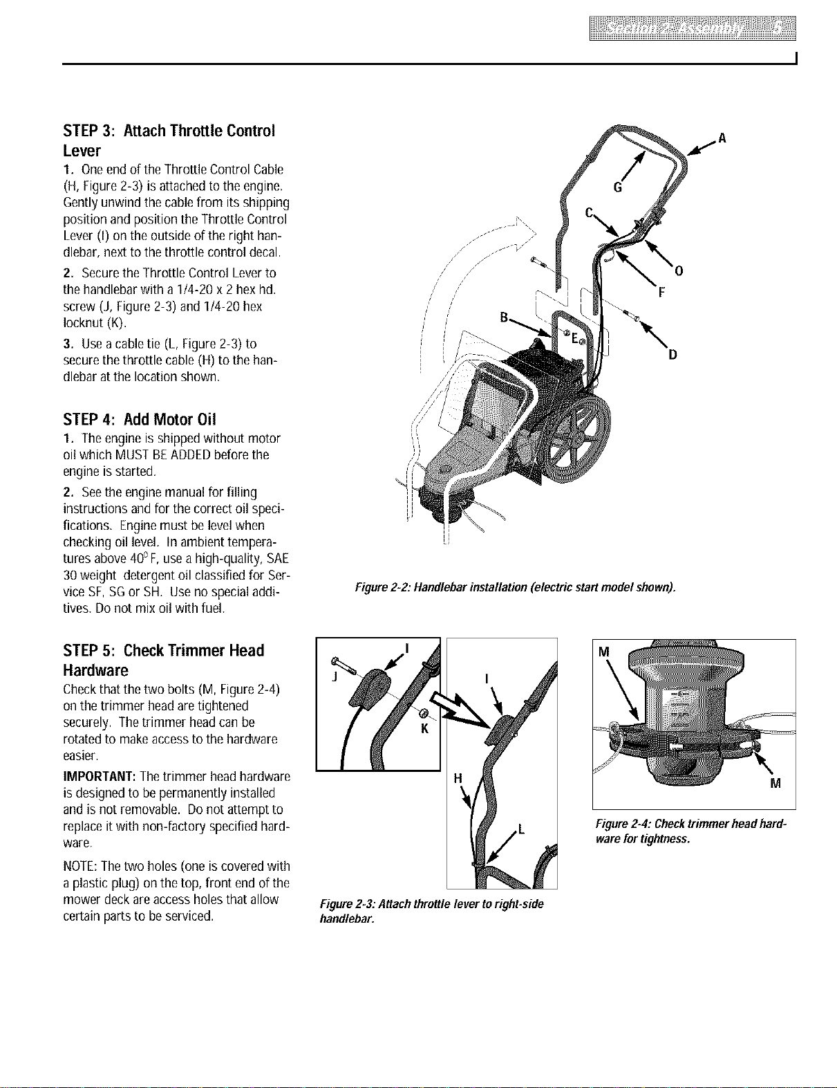
STEP 3: Attach Throttle Control
Lever
1. Oneendof theThrottle Control Cable
(H, Figure2-3) is attachedto the engine.
Gentlyunwind the cablefrom its shipping
position and position the Throttle Control
Lever(I) on the outsideof the right han-
dlebar, next to the throttle control decal.
2. Securethe Throttle Control Leverto
the handlebarwith a 1t4-20 x 2 hexhd.
screw (J, Figure2-3) and1t4-20 hex
Iocknut (K).
3. Usea cabletie (L, Figure2-3) to
securethethrottle cable (H) to the han-
dlebar at the location shown.
STEP 4: Add Motor Oil
1. Theengine is shippedwithout motor
oil which MUSTBEADDEDbeforethe
engine is started.
2. Seethe engine manualfor filling
instructions andfor the correct oil speci-
fications. Enginemust be levelwhen
checking oil level. In ambient tempera-
tures above40oF,usea high-quality, SAE
30weight detergentoil classified for Ser-
vice SF,SGor SH. Useno specialaddi-
tives. Donot mix oil with fuel.
//
/
/
/
/
/
/
f
Figure2-2."Handlebarinstallation (electricstart modelshown).
STEP 5: Check Trimmer Head
Hardware
Checkthat the two bolts (M, Figure2-4)
on the trimmer headaretightened
securely. Thetrimmer headcanbe
rotatedto makeaccessto the hardware
easier.
IMPORTANT:Thetrimmer headhardware
is designedto be permanently installed
and is not removable. Donot attempt to
replaceitwith non-factory specified hard-
ware.
NOTE:Thetwo holes (one iscovered with
a plastic plug) on the top, front end of the
mower deck areaccess holesthat allow
certain parts to beserviced.
I
I
Figure2-3."Attachthrottlelever toright-side
handlebar.
M
Figure2-4:Checktrimmerheadhard=
warefortightness.
STEP6: Connect and Charge
Battery
• Wet conditionscan cause an electric
shock hazard during battery
recharging. Avoid wet conditions
when chargingbattery.
• Rechargingthe battery with improper
equipment could cause a battery
explosion, Use only the battery
charger shipped with the unit. The
engine mustbe shut off and thespark
plug wire disconnected and moved
away from the sparkplug.
Failure to comply could result in per-
sonalinjuryor propertydamage.
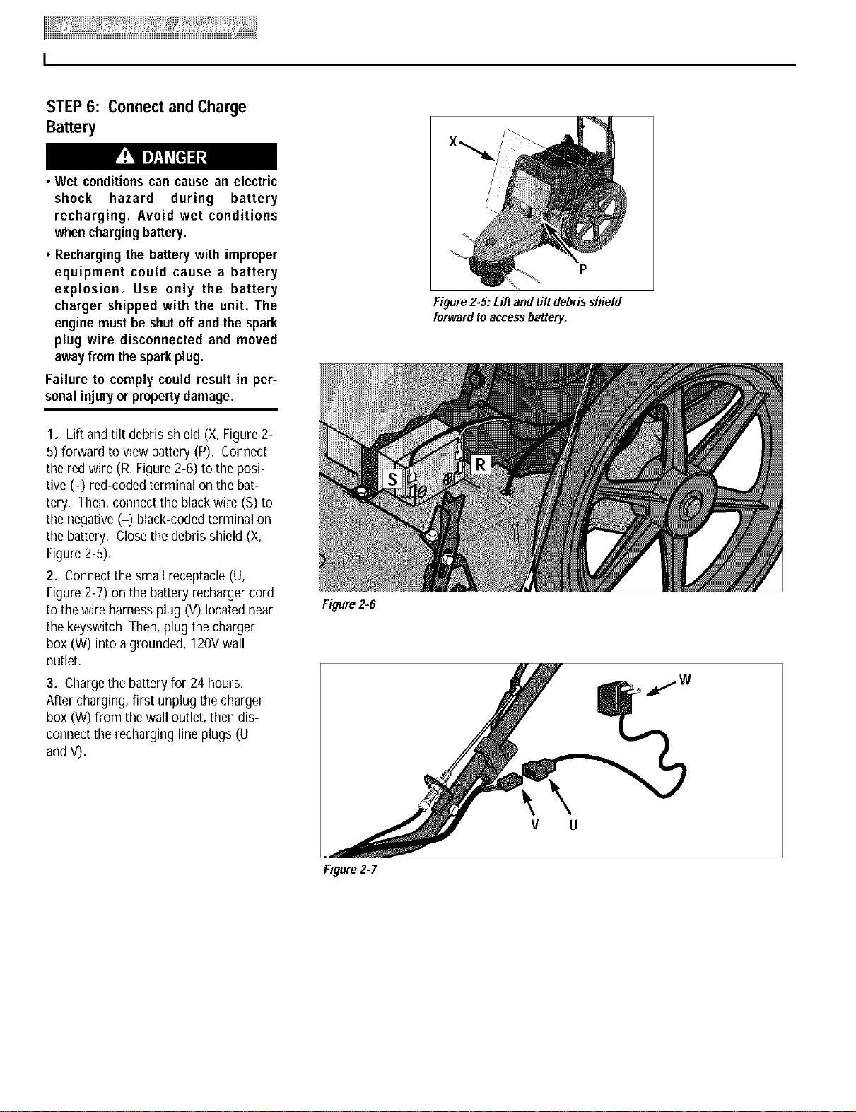
Figure2-5: Lift and tilt debrisshield
forwardto accessbattery.
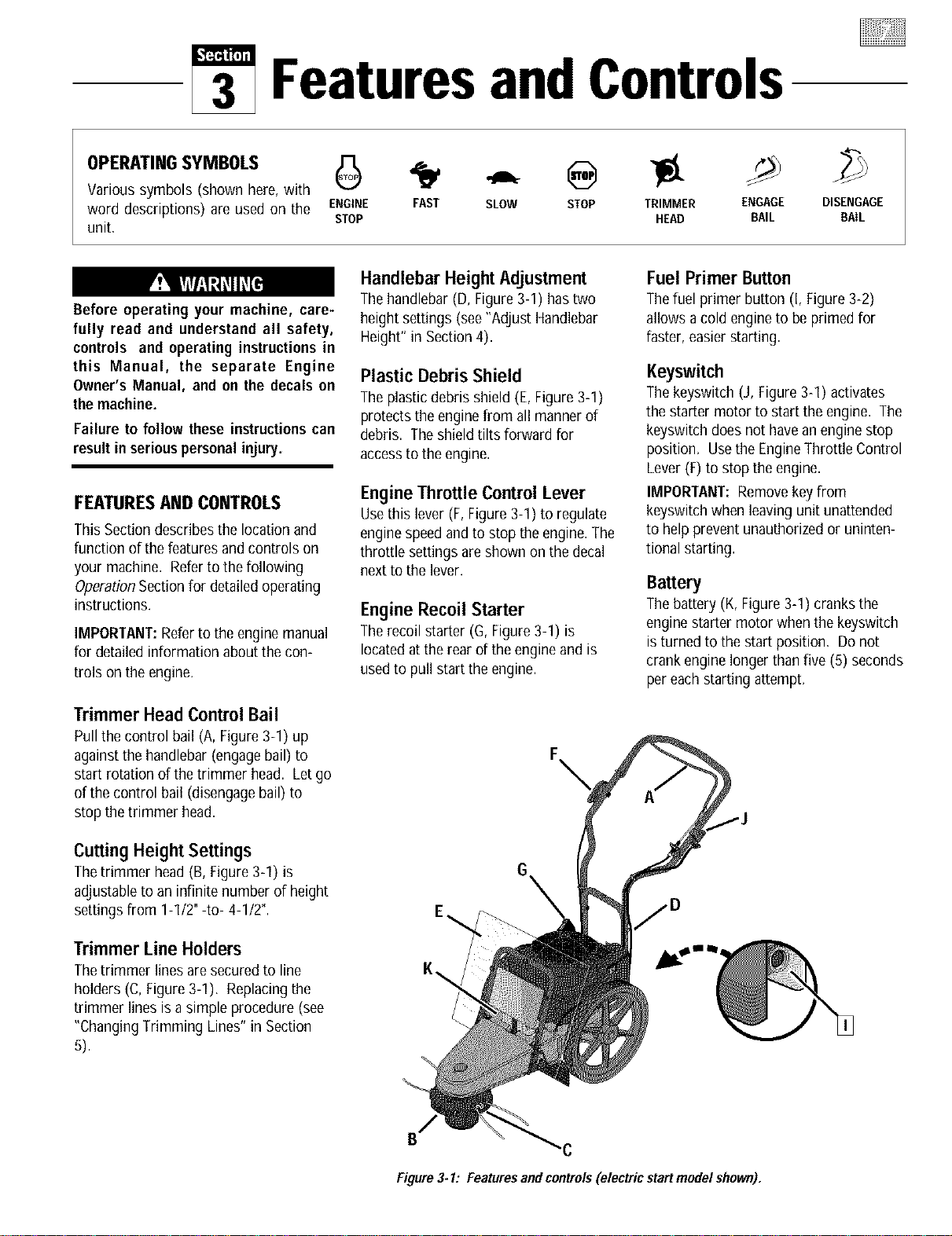
1. Lift and tilt debris shield (X, Figure2-
5) forward to view battery (P). Connect
the red wire (R, Figure2-6) to the posi-
tive (+) red-codedterminal on the bat-
tery. Then,connect the blackwire (S)to
the negative (-) black-codedterminalon
the battery. Closethe debris shield (X,
Figure2-5).
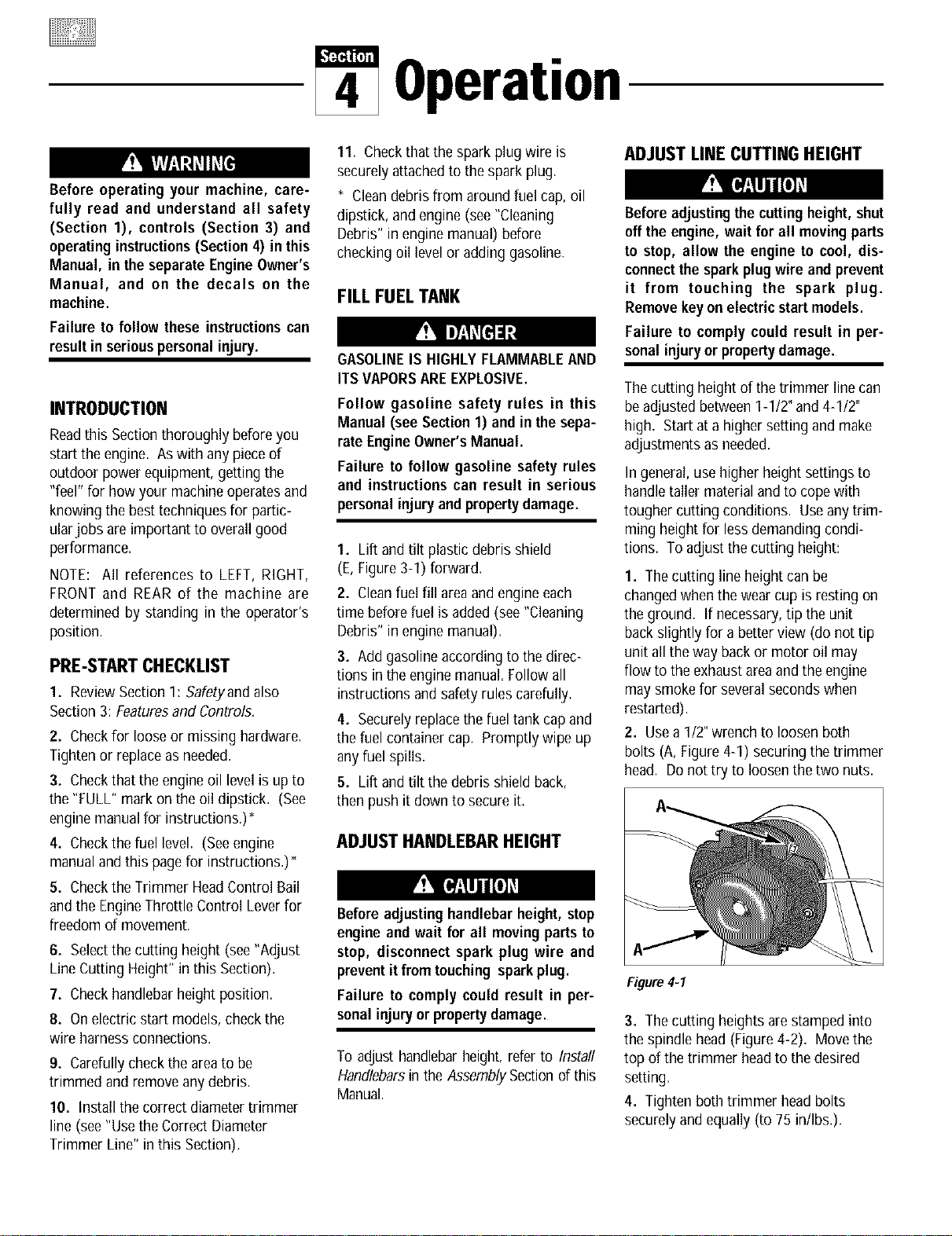
2. Connectthe small receptacle(U,
Figure2-7) on the battery rechargercord
to the wire harnessplug (V)located near
the keyswitch. Then,plug the charger
box (W) into a grounded, 120Vwall
outlet.
3. Chargethe batteryfor 24 hours.
After charging, first unplug the charger
box (W)from the wall outlet, then dis-
connect the recharging line plugs (U
and V).
Figure2_5
V U
Figure2-7
FeaturesandControls
Various symbols (shown here,with
word descriptions) are used on the ENGINE FAST SLOW STOP TRIMMER ENGAGE
STOP HEAD BAIL
unit,
DISENGAGE
BAIL
Before operating your machine, care-
fully read and understand all safety,
controls and operating instructions in
this Manual, the separate Engine
Owner's Manual, and on the decals on
themachine.
Failure to follow these instructionscan
result inseriouspersonalinjury.
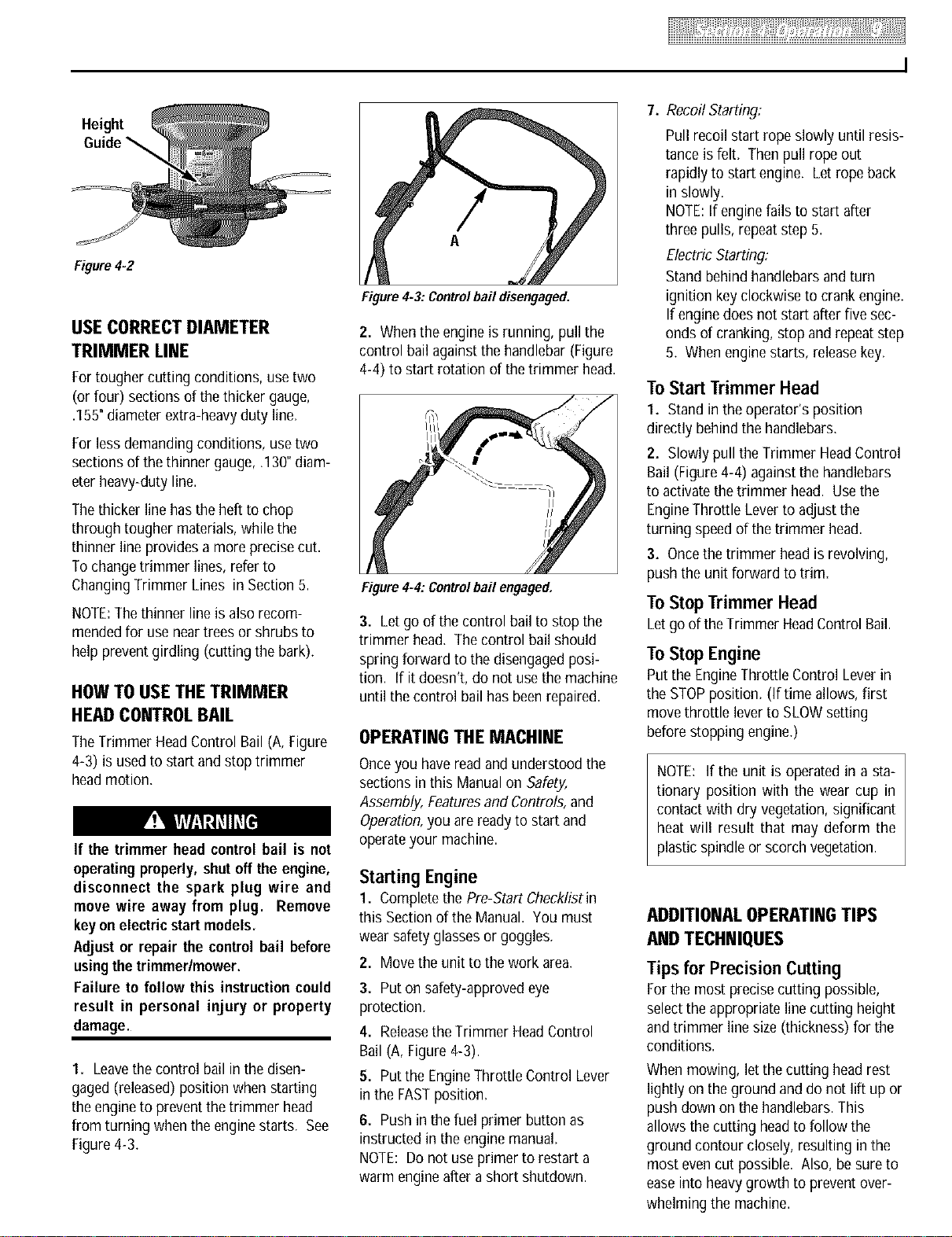
FEATURESAND CONTROLS
This Section describesthe location and
function of thefeatures and controls on
your machine. Referto the following
OperationSectionfor detailedoperating
instructions.
IMPORTANT:Refer to the engine manual
for detailed information about the con-
trois on the engine.
Trimmer Head Control Bail
Pull the control bail (A, Figure3-1) up
againstthe handlebar (engagebail) to
start rotation of the trimmer head. Letgo
of the control bail (disengagebail) to
stop the trimmer head.
CuttingHeightSettings
Thetrimmer head (B,Figure3-1) is
adjustableto an infinite number of height
settings from 1-1/2"-to- 4-1/2".
Trimmer Line Holders
Thetrimmer lines aresecured to line
holders (C, Figure3-1). Replacingthe
trimmer lines is a simple procedure (see
"ChangingTrimming Lines" in Section
5).
Handlebar Height Adjustment
Thehandlebar (D, Figure3-1) hastwo
height settings (see"Adjust Handlebar
Height" in Section4).
Plastic Debris Shield
Theplasticdebris shield (E,Figure3-1)
protects the engine from all mannerof
debris. Theshieldtilts forward for
accessto the engine.
Engine Throttle Control Lever
Usethis lever (F, Figure3-1) to regulate
enginespeedand to stop the engine.The
throttle settings are shown on thedecal
next to the lever.
Engine Recoil Starter
Therecoil starter (G, Figure3-1) is
locatedat the rear of the engine and is
usedto pull start the engine.
Fuel Primer Button
Thefuel primer button (I, Figure3-2)
allows a cold engine to be primed for
faster, easierstarting.
Keyswitch
Thekeyswitch (J, Figure3-1) activates
the starter motor to start the engine. The
keyswitch does not havean engine stop
position. Usethe EngineThrottle Control
Lever(F)to stop the engine.
IMPORTANT:Removekey from
keyswitch when leavingunit unattended
to help prevent unauthorizedor uninten-
tional starting.
Battery
Thebattery (K,Figure3-1) cranks the
enginestarter motor when the keyswitch
is turned to the start position. Donot
crank engine longer thanfive (5) seconds
per eachstarting attempt.
E_
K\
Figure3-1: Featuresand controls(electric startmodel shown).
Operation
Before operating your machine, care-
fully read and understand all safety
(Section 1), controls (Section 3) and
operatinginstructions(Section4) inthis
Manual, in the separate EngineOwner's
Manual, and on the decals on the
machine.
Failure to follow these instructionscan
resultin seriouspersonalinjury.
INTRODUCTION
Readthis Sectionthoroughly beforeyou
start the engine. Aswith any pieceof
outdoor power equipment,getting the
"feel" for how your machineoperatesand
knowing the best techniquesfor partic-
ularjobs are important to overall good
performance.
NOTE: All references to LEFT, RIGHT,
FRONT and REAR of the machine are
determined by standing in the operator's
position.
PRE-STARTCHECKLIST
1. ReviewSection I: Safetyand also
Section3: Featuresand Controls.
2. Checkfor looseor missing hardware.
Tighten or replaceasneeded.
3. Checkthat the engine oil levelis up to
the "FULL" mark on the oil dipstick. (See
engine manualfor instructions.)*
4. Checkthe fuel level. (Seeengine
manualandthis pagefor instructions.)*
5. Checkthe Trimmer HeadControl Bail
and the EngineThrottle Control Leverfor
freedom of movement.
6. Selectthe cutting height (see"Adjust
LineCutting Height" in this Section).
7. Checkhandlebarheight position.
8. Onelectric start models, checkthe
wire harness connections.
9. Carefullycheckthe areato be
trimmed and remove anydebris.
10. Installthe correct diameter trimmer
line (see"UsetheCorrect Diameter
Trimmer Line" in this Section).
11. Checkthat the spark plug wire is
securelyattachedto the spark plug.
* Cleandebris from around fuel cap, oil
dipstick, and engine (see"Cleaning
Debris" in engine manual) before
checkingoil level oradding gasoline.
FILL FUEL TANK
GASOLINEIS HIGHLYFLAMMABLEAND
ITS VAPORSAREEXPLOSIVE.
Follow gasoline safety rules in this
Manual (see Section1) and in the sepa-
rate EngineOwner'sManual.
Failure to follow gasoline safety rules
and instructions can result in serious
personalinjuryand propertydamage.
1. Lift andtilt plastic debris shield
(E,Figure3-1) forward.
2. Cleanfuel fill areaand engine each
time beforefuel is added (see"Cleaning
Debris" in engine manual),
3. Add gasolineaccording to the direc-
tions in the engine manual. Follow all
instructions and safety rulescarefully,
4. Securely replacethe fuel tank capand
thefuel container cap. Promptly wipe up
anyfuel spills.
5. Lift andtilt thedebris shieldback,
then push it down to secureit,
ADJUST HANDLEBARHEIGHT
Beforeadjustinghandlebar height,stop
engine and wait for all movingparts to
stop, disconnect spark plug wire and
preventit from touching sparkplug.
Failure to comply could result in per-
sonalinjury or propertydamage.
To adjust handlebarheight, referto Install
Handlebarsin the AssemblySectionof this
Manual.
ADJUST LINE CUTTING HEIGHT
Beforeadjustingthe cuttingheight,shut
offthe engine, wait for all movingparts
to stop, allow the engine to cool, dis-
connectthe sparkplugwire and prevent
it from touching the spark plug.
Removekeyon electricstartmodels.
Failure to comply could result in per-
sonalinjury or propertydamage.
Thecutting height of the trimmer line can
beadjusted between 1-1/2" and4-1/2"
high. Start ata highersetting and make
adjustmentsas needed.
In general,usehigher height settingsto
handletaller material and to copewith
tougher cutting conditions. Useany trim-
ming height for less demandingcondi-
tions. To adjust the cutting height:
1. Thecutting line height canbe
changedwhen thewear cup is resting on
the ground. If necessary,tip the unit
backslightly for a better view (donot tip
unit all the way back or motor oil may
flow to the exhaustareaandtheengine
may smokefor severalsecondswhen
restarted).
2. Usea 1/2"wrench to loosen both
bolts (A, Figure4-1) securing thetrimmer
head. Donot try to loosen thetwo nuts.
Figure4=1
3. Thecutting heights are stampedinto
the spindle head (Figure4-2). Move the
top of the trimmer headto the desired
setting.
4. Tighten both trimmer head bolts
securelyand equally(to 75 in/Ibs.).
Height
Figure4=2
USE CORRECTDIAMETER
TRIMMER LINE
Fortougher cutting conditions, use two
(or four) sections of thethicker gauge,
.155"diameterextra-heavyduty line.
Forless demandingconditions, usetwo
sections of thethinner gauge,.130"diam-
eter heavy-duty line.
Thethicker line hasthe heft to chop
through tougher materials, while the
thinner line provides a moreprecise cut.
To changetrimmer lines, refer to
ChangingTrimmer Lines in Section5.
NOTE:Thethinner line is also recom-
mendedfor use neartrees or shrubs to
help preventgirdling (cutting the bark).
HOW TOUSE THETRIMMER
HEADCONTROLBAIL
TheTrimmer HeadControl Bail(A,Figure
4-3) is usedto start andstop trimmer
headmotion.
If the trimmer head controlbail is not
operating properly,shut off the engine,
disconnect the spark plug wire and
move wire away from plug. Remove
keyonelectricstartmodels.
Adjust or repair the control bail before
usingthetrimmerlmower.
Failure to follow this instructioncould
result in personal injury or property
damage.
1. Leavethe control bail in the disen-
gaged (released)position when starting
the engineto prevent thetrimmer head
from turning when the enginestarts. See
Figure4-3.
A
Figure4-3: Controlbail disengaged.
2. Whenthe engine is running, pull the
control bail againstthe handlebar (Figure
4-4) to start rotation of thetrimmer head.
Figure4-4: Controlbail engaged.
3. Letgo of the control bailto stop the
trimmer head. The control bail should
spring forward to thedisengagedposi-
tion. If it doesn't, do not usethe machine
until thecontrol bail has beenrepaired.
OPERATINGTHE MACHINE
Onceyou havereadand understood the
sections in this Manualon Safety,
Assembly, Featuresand Controls,and
Operation,you are readyto start and
operateyour machine.
Starting Engine
1. Completethe Pre-Start Checklistin
this Section of the Manual. You must
wear safetyglassesor goggles.
2. Movethe unit to thework area.
3. Puton safety-approvedeye
protection.
4. Releasethe Trimmer HeadControl
Bail (A, Figure4-3).
5. Putthe EngineThrottle Control Lever
in the FASTposition.
6. Pushin the fuel primer button as
instructed in theengine manual.
NOTE: Do not useprimer to restart a
warm engineafter a short shutdown.
7. Recoil Starting:
Pull recoil start rope slowly until resis-
tance isfelt. Thenpull rope out
rapidly to start engine. Let rope back
in slowly.
NOTE:If engine fails to start after
three pulls, repeatstep 5.
Electric Starting:
Standbehind handlebarsand turn
ignition keyclockwise to crank engine.
If enginedoes not start after five sec-
onds of cranking, stop and repeatstep
5. When enginestarts, releasekey.
ToStart Trimmer Head
1. Stand in the operator's position
directly behind the handlebars.
2. Slowly pullthe Trimmer HeadControl
Bail (Figure4-4) againstthe handlebars
to activatethe trimmer head. Usethe
EngineThrottle Leverto adjust the
turning speedof thetrimmer head.
3. Oncethe trimmer headis revolving,
push the unit forward to trim.
To Stop Trimmer Head
Letgo of theTrimmer HeadControl Bail.
ToStopEngine
Putthe EngineThrottle Control Leverin
the STOPposition. (If time allows, first
move throttle leverto SLOWsetting
beforestopping engine.)
NOTE: If the unit is operated in a sta-
tionary position with the wear cup in
contact with dry vegetation, significant
heat will result that may deform the
plastic spindleor scorch vegetation.
ADDITIONALOPERATINGTIPS
ANDTECHNIQUES
Tips for Precision Cutting
Forthe most precisecutting possible,
selectthe appropriateline cutting height
and trimmer line size (thickness) for the
conditions.
Whenmowing, letthe cutting head rest
lightly on theground and do not lift up or
push down on the handlebars.This
allows the cutting headto follow the
ground contour closely, resulting in the
most evencut possible. Also, besure to
easeinto heavygrowth to preventover-
whelming the machine.

THROWNOBJECTHAZARD
• Objects such as rocks, pebbles, and
small debris will be thrownviolently
by the cutting head, resulting in sig-
nificant hazard to eyes and exposed
bodyparts,
• Always wear safety-approved eye
protection and suitable clothing and
footwear.
• Keep children, pets and bystanders
50 feet away from machine while
operating.
• Be alert tohiddenobstacles.
Failure to complycould result in injury
or propertydamage.
Vary Throttle Setting
For Conditions
Themajority of trimming and mowing
jobs will yield the best results if the
enginethrottle is set atthe fastest engine
speed.
Lessdemandingjobs (and projects that
require very precisecutting) mayyield
betterresults if the enginespeedis
backedoff somewhat. (Forexample,
damageto trees and shrubs canbe
avoidedby reducing the enginespeed;
using the lighter .130"diameter line; and
bykeepinga safedistance away.)
Again,onceyou begina particularjob
and geta "feel"for the conditions, you
will beable to makeadjustments for the
best possible results.
Use Correct Walking Speed
Usea walking speedthat issuitable for
the mowing conditions. You'll get better
results at slower walking speedsif the
growth is tall or lush. Shortergrassor
less densegrowth canbecut atfaster
walking speeds.
Trim When Wet or Dry
Grassand most other materialsare most
efficiently trimmed whendry. But, the
unit will do a finejob evenwith damp or
wet materials. Whenconditions are
moist or damp, be sureto clean debris
off the machineregularly to keepcutting
efficiency high. And watch your footing!
Do Not Let the Trimmer
Lines Become Too Short
Oncethe trimmer lines are worn to less
than 1/2 their original length, trimming
jobs begin to take far longer than they
should.
Asa generalguideline, oncethe line
length becomeshalf of its original length,
it's time to changeto new lines.
Use Extreme Caution on Slopes
Whenoperatingon sloping ground, use
extremecaution and common sense to
avoidpossible injury or property damage.
Donot mow on excessivelysteepslopes!
Avoid slopes if greaterthan 150or wher-
everfooting is unsure. Ifa slope is diffi-
cult to stand on, it is probablytoo steep
to trim or mow. Inthis case,it may be
wiser to establish a permanentground
cover on this area.
Donot trim on slopeswhen the ground is
slippery. Trim acrossthe face of a slope,
not up and down. Slowdown and exer-
cise caution when changingdirection on
slopes.
Keep the Mowed Side to Your
Right as You Move Ahead
Theunit feeds cut materials to the right
side. Stay on the right sideof unmowed
growth asyou move along.
Clean the Unit Frequently
Cleanunder the mower deck frequently to
removeany grass buildup. Alsoclean
aroundthe muffler and on top of engine.
Seethe cleaning instructions in Section5.
Trimming/Mowing Quick Reference Chart
This Quick ReferenceChart is providedasa generalreference. Experiment
with your unit to determine the best settings for the conditions.
Height Diameter Speed Speed
.... (Note1) (Note 2) (Note 3) (Note 4)
LightGrowth Any .130"or .155" Fast Any
(Note 6)
Start high, .130"or .155"
Tall Growth progressively (Note6) Fast SlowPace
lower
Heavy/Tough Any .155" Fast SlowPace
Growth (Note6)
Trimming .130"
Near Trees Any (Note7) Slow SlowPace
and Shrubs
(Note 5)
NOTES:
1. See"Adjust Line Cutting
Height."
2. See"Use Correct Diam-
eter Trimmer Line,"
3. See"Vary Throttle Setting
ForConditions."
4. See"Use Correct Walking
Speed,"
5. See"Tips for Precision
Cutting."
6. See"Changing Trimmer
Lines" in Section5,
7. Lighter line helps prevent
damageto bark.

Maintenance
Beforeinspecting,cleaningor servicingthe machine, shut off engine, discon-
nectsparkplugwire, and make surethatall movingpartshavecometo a com-
plete stop. Removeignitionkeyonelectricstartmodels.
Failure to follow these instructionscan result in personal injury or property
damage.
NOTE: LEFTand RIGHTsides of unit areas viewed
from operator's position behind the handlebars.
REQUIREDMAINTENANCESCHEDULE
BEFOREEVERY EVERY EVERY AS
REQUIREDMAINTENANCE EACH 5 25 100 NOTED
USE HOURSHOURSHOURS
CHECKENGINEOIL LEVEL
CHECKTRIMMERLINES 1
CHECKTRIMMERHEADENGAGEMENT
MACHINECLEANING 3
CHECKNUTSANDBOLTS
CHANGEENGINEOIL 2, 5
SERVICEAIR FILTERSYSTEM 5
CLEANUNDERDECK
GENERALLUBRICATION
INSPECTDRIVEBELT
CLEANENGINE 4
CHECKWEARCUP 6
Chart5-1
ADJUSTING TRIMMER
HEADENGAGEMENT
Thetension on the drive belt must be
correct for proper operation of the
trimmer head. If the tension is correct,
the trimmer headwill rotate whenthe
Trimmer HeadControl Bail is pulled back
againstthe handlebar.
A looseor worn drive beltwill causethe
trimmer headto move slowly, or not at
all,when the control bail is engaged(belt
squealingmay also be noticeable).
If thebelt tension is too tight, the
trimmer headmay rotate beforethecon-
trol bail is engaged,or whenthere is no
freeplay in the control bail. Toadjust
belttension:
1. Stopthe engine and wait for all parts
to stop moving. Adjust the position of
the two jam nuts on the control cable
adjustment stud (seeFigure5-2) as
describednext:
a. Totighten belt tension, movethe
upper nut (A, Figure5-2) upwardone
or two full turns, then move the lower
nut (B) upward. Tighten both nuts
securely. Test unit and readjustjam
nuts asneeded.
b. To loosenbelt tension, move the
lower nut (B, Figure5-2) downward
one or two full turns and then move
the upper nut (A) down. Tightenboth
nuts securely. Testunit and readjust
jam nuts asneeded.
NOTE1- Newline replacementis suggestedwhen old lineis 50% or lessof original length.
NOTE2- Changeoil after first two hours of newoperation; thereafter every25 hours.
NOTE3- Cleandailyif usedinextremelydusty/dirtyconditions (seeenginemanual).
NOTE4- Cleanbefore using machine and ateachfuel refill,
NOTE5- Servicemore often if used inextremely dusty or dirty conditions (seeengine
manual).
NOTE6- Replacewhen severe gougesexist on bottom surface.
A
B
Figure5-2".Belttensionadjustment.
I
_ Before inspecting, cleaning or servicing the machine, shut off engine, wait for all moving parts to
come to a stop, disconnect spark plug wire and move wire away from spark plug. Remove key on I
electric start models. I
Failure to follow these instructionscanresult in serious personal injury or propertydamage, m
REMOVING AND REPLACING
THE TRIMMER HEAD
1. Stopthe engine andwait for all
moving parts to stop. Disconnectspark
plug wire and move it away from the
spark plug. Removethe ignition keyon
electric start models.
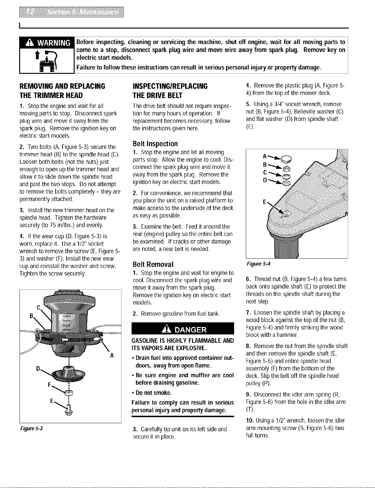
2. Two bolts (A, Figure5-3) securethe
trimmer head (B) to the spindlehead (C).
Loosenboth bolts (not the nuts)just
enough to open up thetrimmer headand
allow itto slide down the spindle head
and past the two stops. Do not attempt
to removethe bolts completely - theyare
permanentlyattached.
3. Installthe newtrimmer head on the
spindle head. Tighten the hardware
securely (to 75 in/Ibs.) and evenly.
4. If the wearcup (D, Figure5-3) is
worn, replaceit. Usea 1/2" socket
wrench to removethe screw (E,Figure5-
3) and washer (F). Install the newwear
cup and reinstall the washer and screw.
Tighten the screw securely.
Figure 5-3
INSPECTING/REPLACING
THE DRIVE BELT
Thedrive belt should not require inspec-
tion for many hours of operation. If
replacementbecomesnecessary,follow
the instructions given here.
Belt Inspection
1. Stop the engineand let all moving
parts stop. Allow the engineto cool. Dis-
connectthe spark plug wire and move it
awayfrom thespark plug. Removethe
ignition key on electric start models.
2. For convenience,we recommend that
you placethe unit on a raisedplatform to
makeaccessto the undersideof the deck
aseasyas possible.
3. Examinethe belt. Feedit around the
rear (engine) pulley so the entirebelt can
be examined. If cracks or other damage
are noted, a new belt is needed.
Belt Removal
1. Stop the engineand wait for engineto
cool. Disconnectthe spark plug wire and
move it away from the spark plug.
Removethe ignition key on electricstart
models.
2. Removegasolinefrom fuel tank.
GASOLINEIS HIGHLYFLAMMABLEAND
ITS VAPORSAREEXPLOSIVE.
• Drainfuel intoapprovedcontainerout-
doors,away from openflame.
• Be sure engine and muffler are cool
beforedraininggasoline.
• Donot smoke.
Failure to complycan result in serious
personalinjuryand propertydamage.
3. Carefullytip unit on its left side and
secure it in place.
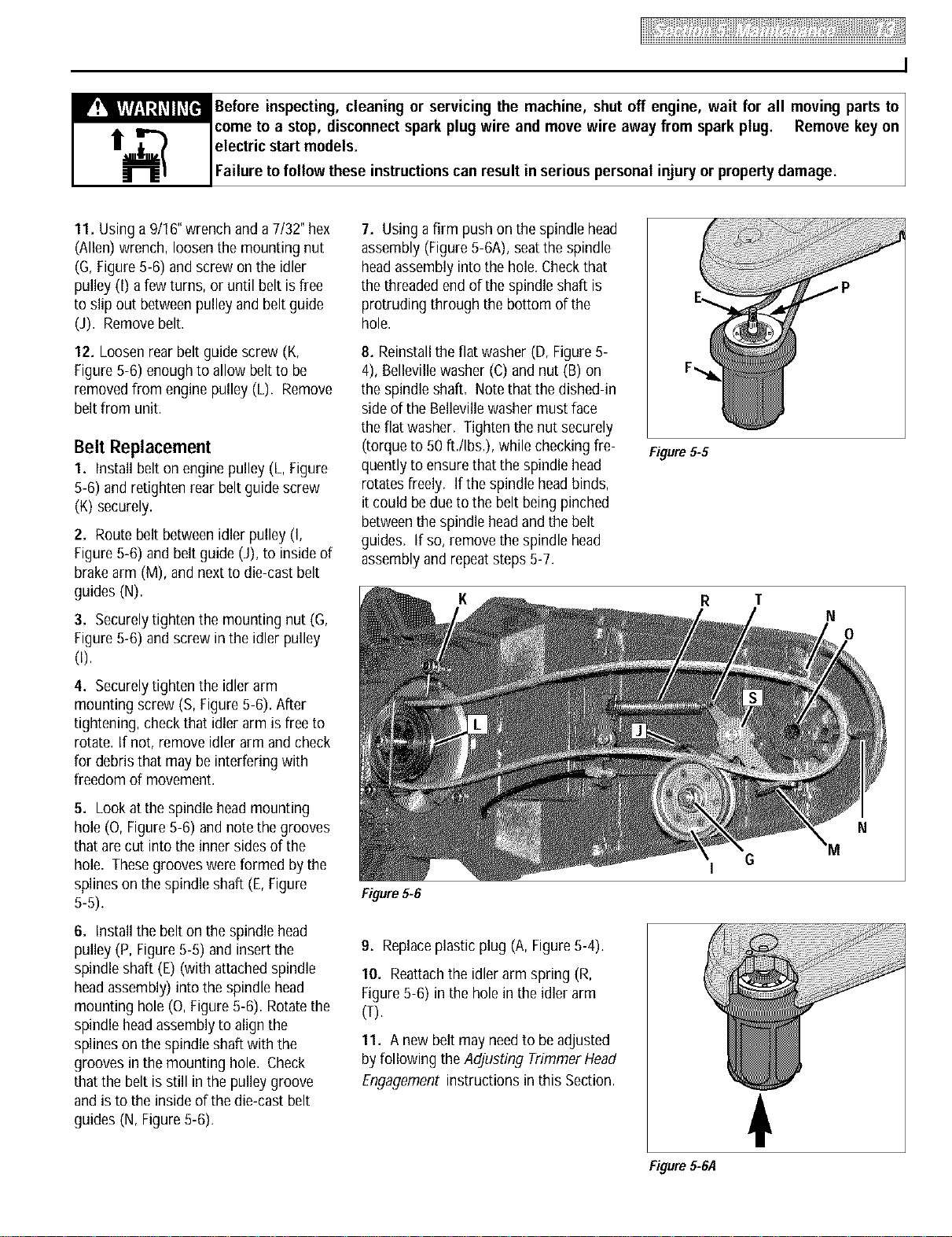
4. Removethe plasticplug (A, Figure5-
4) from thetop of the mower deck.
5. Using a 3t4" socketwrench, remove
nut (B, Figure5-4), Bellevillewasher (C)
and flat washer (D)from spindle shaft
(E).
Figure5-4
6. Threadnut (B, Figure5-4) afew turns
backonto spindle shaft (E)to protect the
threads on the spindle shaft during the
next step.
7. Loosenthe spindle shaft by placinga
wood block against thetop of the nut (B,
Figure5-4) andfirmly striking the wood
block with a hammer.
8. Removethe nutfrom the spindle shaft
andthen remove the spindle shaft (E,
Figure5-5) andentirespindle head
assembly (F)from the bottom of the
deck.Slip the belt off the spindle head
pulley (P).
9. Disconnectthe idler arm spring (R,
Figure5-6) from the hole in the idler arm
(T).
10. Using a 1/2"wrench, loosenthe idler
arm mounting screw (S, Figure5-6) two
full turns.
I
Before inspecting, cleaning or servicing the machine, shut off engine, wait for all moving parts to ]
come to a stop, disconnectspark plug wire and move wire away from spark plug. Remove key on ]
electric start models. I
Failure to follow these instructionscan result in serious personal injury or propertydamage. I
11. Using a 9/16"wrench and a 7/32" hex
(Allen) wrench, loosenthe mounting nut
(G,Figure5-6) andscrew on the idler
pulley (0 a few turns, or until belt is free
to slip out betweenpulley and beltguide
(J). Removebelt.
12. Loosenrear belt guide screw (K,
Figure5-6) enoughto allow beltto be
removedfrom engine pulley (L). Remove
belt from unit.
Belt Replacement
1. Install belt on engine pulley (L, Figure
5-6) and retighten rear beltguide screw
(K) securely.
2. Route belt betweenidler pulley (I,
Figure5-6) andbelt guide (J), to insideof
brakearm (M), and nextto die-cast belt
guides (N).
3. Securelytighten the mounting nut (G,
Figure5-6) andscrew in the idler pulley
0).
4. Securelytighten the idlerarm
mounting screw (S, Figure5-6). After
tightening, checkthat idler arm is freeto
rotate. If not, remove idler arm and check
for debris that may be interfering with
freedom of movement.
5. Lookat the spindlehead mounting
hole (O, Figure5-6) andnotethe grooves
that are cut into the inner sidesof the
hole=Thesegrooves wereformed by the
splines on the spindle shaft (E,Figure
5-5).
6. Installthe belt on the spindlehead
pulley (P, Figure5-5) andinsert the
spindle shaft (E) (with attachedspindle
headassembly) into the spindlehead
mounting hole (0, Figure5-6). Rotatethe
spindle headassemblyto align the
splines on the spindle shaft with the
grooves in themounting hole. Check
that the belt is still in the pulley groove
and is to the inside of the die-cast belt
guides (N, Figure5-6).
7. Using a firm pushon the spindle head
assembly (Figure5-6A), seatthe spindle
headassembly into the hole.Checkthat
the threadedend of the spindle shaft is
protruding through the bottom of the
hole.
8. Reinstallthe flat washer (D, Figure5-
4), Bellevillewasher (C)and nut (B) on
the spindle shaft. Notethat the dished-in
sideof the Bellevillewasher must face
the flat washer. Tighten the nut securely
(torque to 50 ft./Ibs.), while checkingfre-
quently to ensurethat the spindlehead
rotatesfreely. If the spindle headbinds,
it could be due to the belt being pinched
betweenthe spindle headand the belt
guides. If so,remove the spindle head
assembly and repeatsteps5-7.
Figure5-6
9. Replaceplastic plug (A,Figure5-4).
10. Reattachthe idler arm spring (R,
Figure5-6) in the hole in the idler arm
(T).
11. A new beltmay needto be adjusted
byfollowing theAdjusting TrimmerHead
Engagement instructions in this Section.
Figure5-5
R
Figure5-6,4
T
6
N
0
N
I
_ Before inspecting, cleaning or servicing the machine, shut off engine, wait for all moving parts to
come to a stop, disconnect spark plug wire and move wire away from spark plug. Remove key on I
electric start models. I
Failure to follow these instructionscanresult in serious personal injury or propertydamage. I
GENERALENGINETRIMMER/MOWER CLEANING
AND DEBRIS REMOVAL
Thoroughand regularcleaningof debris
from theengine and the machine is
required for maximum engine efficiency
and good overallperformance. Inspect
and cleanthe following areasregularly,
making surethe engine is stopped,and
cool, before proceeding:
• Brush andwipe off allengine surfaces,
especiallybeforechecking oil oradding
fuel. Donot letdebris, oil or grease
accumulate. To accessthe front of the
engine, lift the debris shield up and tilt
it forward,
• Wipethe deck clean, particularly near
the enginemuffler.
• Cleanthe undersideofthe deck.
• Keepsafetyand operatingdecals clean
and legible.
• Keepalloperating control levers
debris-free so they work properly.
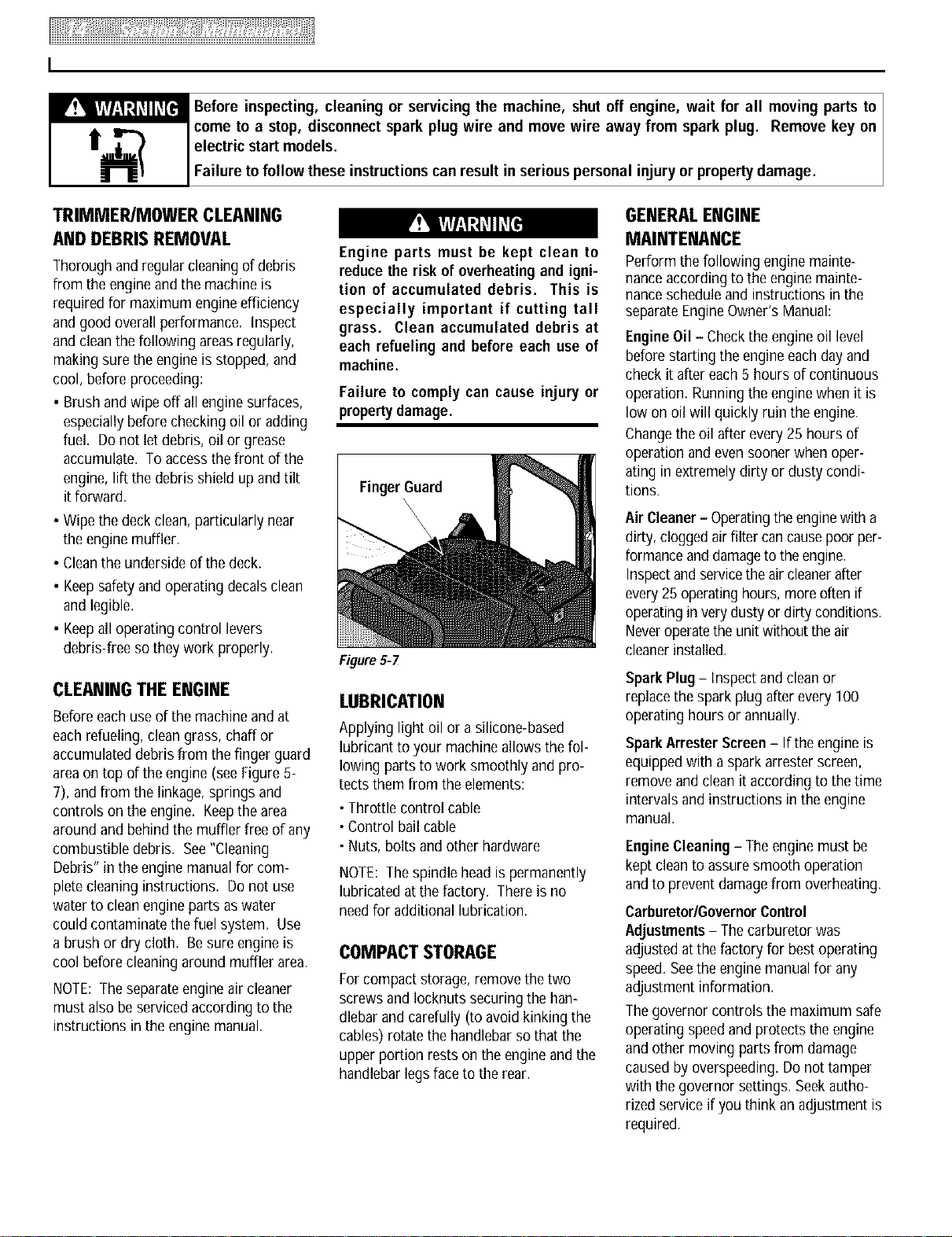
CLEANINGTHE ENGINE
Beforeeachuse of the machineand at
eachrefueling, clean grass,chaff or
accumulated debris from the finger guard
areaon top of the engine (seeFigure5-
7), andfrom the linkage, springs and
controls on the engine. Keepthe area
around and behindthe muffler free of any
combustible debris. See"Cleaning
Debris"in the enginemanualfor com-
pletecleaninginstructions. Donot use
water to cleanengineparts aswater
could contaminate the fuel system. Use
a brushor dry cloth. Besure engine is
cool before cleaningaround muffler area.
NOTE:Theseparateengineair cleaner
must alsobe servicedaccordingto the
instructions in the engine manual.
Engine parts must be kept clean to
reducethe risk of overheatingand igni-
tion of accumulated debris. This is
especially important if cutting tall
grass. Clean accumulated debris at
each refueling and before each use of
machine.
Failure to comply can cause injury or
propertydamage.
FingerGuard
\
\
\
\
FigureSW
LUBRICATION
Applying light oil or a silicone-based
lubricant to your machineallows the fol-
lowing parts to work smoothly and pro-
tects them from the elements:
•Throttle control cable
•Control bailcable
•Nuts, boltsand other hardware
NOTE:Thespindle head is permanently
lubricated atthe factory. Thereis no
needfor additional lubrication.
COMPACT STORAGE
Forcompact storage, removethe two
screwsand Iocknutssecuring the han-
dlebar and carefully (to avoid kinking the
cables) rotate the handlebarso that the
upper portion restson the engineand the
handlebarlegsface to the rear.
MAINTENANCE
Perform the following engine mainte-
nanceaccording to the engine mainte-
nanceschedule and instructions in the
separate EngineOwner's Manual:
EngineOil - Checkthe engine oil level
beforestarting the engine eachdayand
check it after each5 hours of continuous
operation. Runningthe enginewhen it is
low on oil will quickly ruin the engine.
Changethe oil after every 25 hoursof
operation and evensoonerwhen oper-
ating in extremely dirty or dusty condi-
tions.
AirCleaner- Operatingthe enginewith a
dirty, cloggedair filter cancausepoorper-
formanceand damageto the engine.
Inspectandservicetheair cleanerafter
every25 operatinghours, more often if
operatingin very dusty or dirty conditions.
Neveroperatethe unitwithout the air
cleanerinstalled.
Spark Plug- Inspect and cleanor
replacethe spark plug afterevery 100
operating hours or annually.
Spark ArresterScreen- If theengine is
equipped with a spark arrester screen,
remove and clean it according to the time
intervalsand instructions in the engine
manual.
EngineCleaning - Theengine must be
kept cleanto assuresmooth operation
and to preventdamagefrom overheating.
Carburetor/GovernorControl
Adjustments- Thecarburetorwas
adjusted at thefactory for best operating
speed. Seethe engine manualfor any
adjustment information.
Thegovernor controls the maximum safe
operating speedand protects the engine
and other moving parts from damage
caused byoverspeeding.Do not tamper
with the governor settings. Seekautho-
rized serviceif you think anadjustment is
required,
I
_Sefore inspecting, cleaning or servicing the machine, shut off engine, wait for all moving parts to I
come to a stop, disconnectspark plug wire and move wire away from spark plug. Remove key on I
electric start models. I
Failure to follow these instructionscan result in serious personal injury or propertydamage. I
ThrottleControlAdJustment- If the
enginedoesnot shut off whenthethrottle
leveris movedto the stop position, or if
the enginedoes notrespondto various
throttle settings,referto the engine
manualfor serviceinformation.
0FF-SEASONSTORAGE
When storing the unit for extended
periods,follow these proceduresto
ensurethat the unit will be in goodcondi-
tion for future use.
• Never perform maintenance when
engine isrunningor sparkplugwire is
connected,except when instructedto
do so.
• Never store mower with fuel in fuel
tank inside a building where fumes
can reach an openflame or spark,or
where ignition sources are present
such as hot water and spaceheaters,
furnaces, clothesdryers,stoves, elec-
tric motors, etc. Make sure engine is
coolbeforestoring.
• Drain gasoline outdoors into an
approvedcontainer.Donot smokeand
keepfuel away from openflame.
Failure to follow these instructionswill
result in serious personal injury or
propertydamage.
• Store machineon alevelsurface.
• Inspectfor any loose,broken or
missing parts. Repairor replaceparts
as needed.
•Perform recommendedenginemainte-
nancebyfollowing the enginestorage
instructions found in the enginemanual.
Be sureto protect thefuel lines, carbu-
retor and fueltank from gumdeposits
by removing fuel or bytreating fuel with
a fuel stabilizer(follow enginemanufac-
turer's recommendations).
• Cleananydirt, grass or chaff from the
air cooling system intakeareaand other
parts of the engine.
• Onan electric startmodel, removekey
from keyswitch. Chargebatteryfor 24
hours beforeand after storage.
• Disconnectspark plug wire andmove
wire awayfrom spark plug.
BATTERYSERVICE
BatteryRecharging
Rechargethe battery before and after
storing the unit for more than three
weeks.
• Wet conditionscan cause an electric
shockhazardduring battery charging.
Avoidwet conditionswhen charging.
• Rechargingthe battery with improper
equipment could cause a battery
explosion. Use only the battery
chargershippedtoyou. All partsmust
be fully stopped and the spark plug
wire disconnected and moved away
from thesparkplug.
Failure to comply could result in per-
sonalinjuryor propertydamage.
Theengine must be stopped and the area
in which rechargingwill take placemust
be dry.
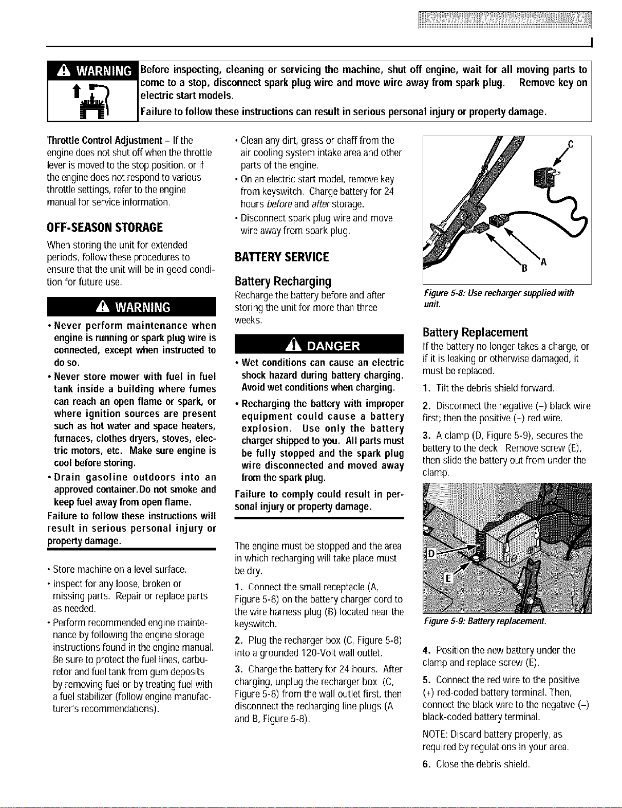
1. Connectthe small receptacle(A,
Figure5-8) onthe batterychargercord to
the wire harness plug (B) located nearthe
keyswitch.
2. Plug therecharger box (C, Figure5-8)
into a grounded 120-Volt wall outlet.
3. Chargethe battery for 24 hours. After
charging, unplug the rechargerbox (C,
Figure5-8) from the wall outlet first, then
disconnect the recharging line plugs (A
and B, Figure5-8).
/
Figure 5-8: Userecharger suppliedwith
unit.
Battery Replacement
If the battery no longer takesa charge, or
if it is leakingor otherwise damaged,it
must be replaced.
1. Tilt thedebris shield forward.
2. Disconnectthe negative(-) blackwire
first; then the positive (+) red wire.
3. A clamp (D,Figure5-9), securesthe
batteryto thedeck. Removescrew (E),
then slidethe battery out from under the
clamp.
Figure 5-9: Batteryreplacement.
4. Position the newbattery underthe
clamp and replacescrew (E).
5. Connectthe red wire to the positive
(+) red-coded batteryterminal. Then,
connectthe blackwire to the negative(-)
black-codedbattery terminal.
NOTE:Discard battery properly, as
required by regulations in your area.
6. Closethe debris shield.
I
_ Before inspecting, cleaning or servicing the machine, shut off engine, wait for all moving parts to
come to a stop, disconnect spark plug wire and move wire away from spark plug. Remove key on I
electric start models. I
Failure to follow these instructionscanresult in serious personal injury or propertydamage. I
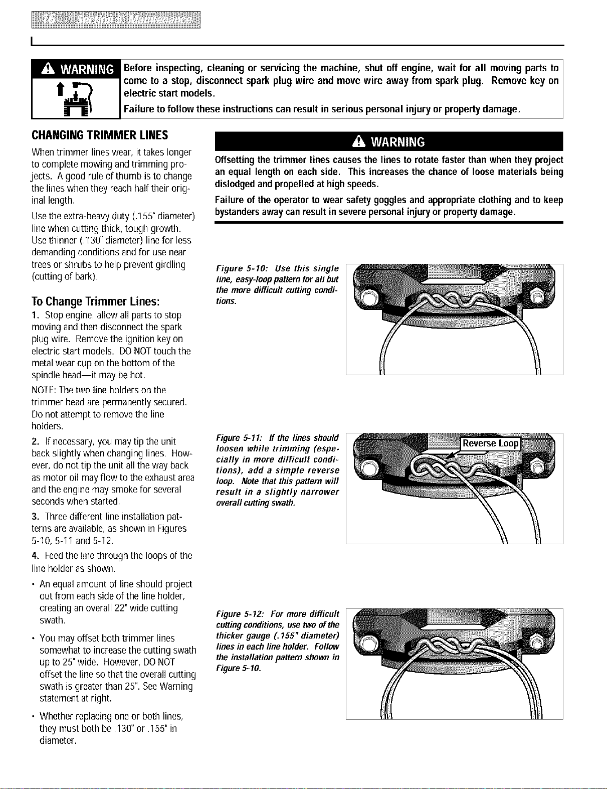
CHAN61NGTRIMMER LINES
Whentrimmer lineswear, ittakes longer
to complete mowing and trimming pro-
jects. A good rule of thumb isto change
the lineswhen they reachhalftheir orig-
inal length.
Usethe extra-heavyduty (.155"diameter)
linewhen cutting thick, tough growth.
Usethinner (.130" diameter) line for less
demandingconditions and for usenear
trees or shrubs to help prevent girdling
(cutting of bark).
ToChange Trimmer Lines:
1. Stopengine,allow all partsto stop
moving and then disconnect the spark
plug wire. Removethe ignition key on
electric start models= DONOTtouchthe
metalwear cupon the bottom of the
spindle head--it may behot.
NOTE:Thetwo line holderson the
trimmer head are permanentlysecured.
Donot attempt to remove the line
holders.
2. If necessary,you may tip the unit
backslightly when changing lines. How-
ever, do not tip the unit all the way back
as motor oil may flow to the exhaustarea
and the enginemay smokefor several
secondswhen started.
3. Threedifferent line installation pat-
terns areavailable,as shown in Figures
5-10, 5-11 and 5-12.
4, Feedthe line through the loops of the
line holder as shown.
• An equal amount of lineshould project
out from eachsideof the line holder,
creating an overall 22"wide cutting
swath.
• Youmay offsetboth trimmer lines
somewhat to increasethecutting swath
up to 25" wide. However, DONOT
offset the line so that the overall cutting
swath is greaterthan 25". SeeWarning
statement at right.
Offsettingthe trimmer lines causesthe lines to rotate faster than when they project
an equal length on each side. This increasesthe chanceof loosematerials being
dislodgedand propelledat highspeeds.
Failure of the operatortowear safetygogglesand appropriateclothingand to keep
bystandersawaycanresultin severepersonalinjuryor propertydamage.
Figure 5-10: Use this single
line, easy-loop pattern fora# but
the more difficult cutting condi-
tions.
Figure 5-11: ff the lines should
loosen while trimming (espe.
cially in more difficult condi-
tions), add a simple reverse
loop. Note that this pattern will
result in a slightly narrower
overall cuttingswath.
Figure 5-12: For more difficult
cuttingconditions,use twoofthe
thicker gauge (. 155" diameter)
lines in each line holder. Follow
the installation pattern shownin
Figure5=10.
• Whetherreplacing one or both lines,
they must both be .130"or .155"in
diameter.
I
_Before inspecting, cleaning or servicing the machine, shut off engine, wait for all moving parts to I
come to a stop, disconnectspark plug wire and move wire away from spark plug. Remove key on I
electric start models. I
I
Failure to follow these instructionscan result in serious personal injury or propertydamage. I
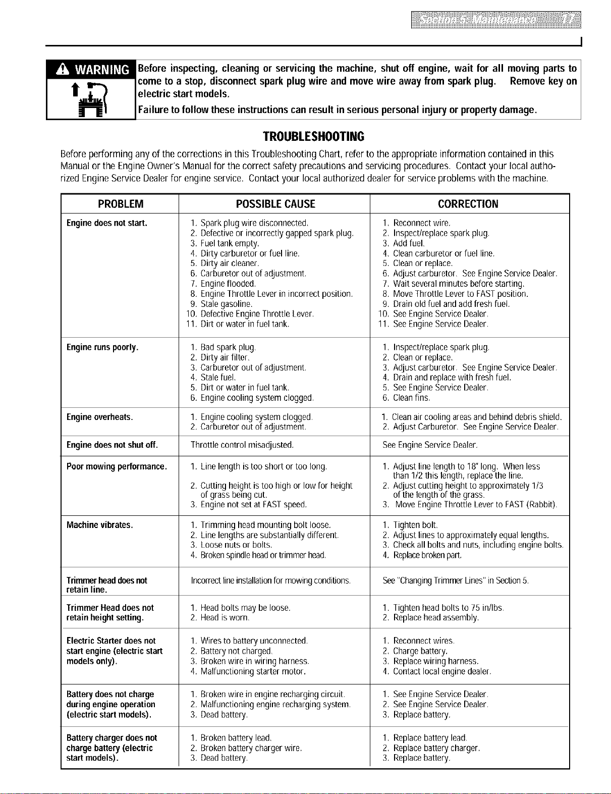
TROUBLESHOOTING
Before performing any of the corrections in this Troubleshooting Chart, refer to the appropriate information contained in this
Manual or the Engine Owner's Manual for the correct safety precautions and servicing procedures. Contact your local autho-
rized Engine Service Dealer for engine service. Contact your local authorized dealer for service problems with the machine.
PROBLEM POSSIBLECAUSE CORRECTION
Enginedoesnotstart.
1,
2.
3.
4.
5,
6.
7.
8.
9.
10.
11.
Sparkplug wire disconnected, 1.
Defectiveor incorrectly gapped spark plug. 2.
Fueltank empty. 3.
Dirty carburetor or fuel line, 4,
Dirty air cleaner. 5,
Carburetor out of adjustment. 6,
Engineflooded. 7,
EngineThrottle Leverin incorrect position. 8,
Stalegasoline, 9,
DefectiveEngineThrottle Lever. 10,
Dirt orwater in fuel tank. 11.
1,
2,
Reconnectwire.
Inspect/replacespark plug.
Add fuel,
Cleancarburetor or fuel line.
Cleanor replace,
Adjust carburetor, SeeEngineService Dealer.
Wait several minutes before starting,
Move Throttle Leverto FASTposition.
Drain old fuel and add fresh fuel.
See EngineServiceDealer,
See EngineServiceDealer.
Enginerunspoorly. 1. Badspark plug, Inspect/replacespark plug.
2. Dirty airfilter, Cleanor replace,
3. Carburetor out of adjustment. 3, Adjust carburetor. SeeEngineService Dealer.
4. Stalefuel, 4, Drain and replacewith fresh fuel.
5. Dirt or water in fuel tank, 5, See EngineServiceDealer.
6. Enginecooling system clogged. 6. Cleanfins.
Engineoverheats. 1. Enginecooling system clogged. 1. Cleanair cooling areasandbehind debrisshield,
2. Carburetor out of adjustment. 2. Adjust Carburetor. SeeEngineService Dealer.
Enginedoes notshutoff. Throttle control misadjusted. SeeEngineServiceDealer.
Poormowingperformance. 1. Line length is too short or too long. 1. AdJuStline length to 18" long, When less
than 1/2 this length, replace the line.
2. Cutting height istoo high or low for height 2. Adjust cutting height to approximately 1/3
of grass beingcut, of the length of thegrass,
3. Enginenot set at FASTspeed. 3. Move EngineThrottle Lever to FAST(Rabbit).
Machinevibrates. 1. Trimming headmounting bolt loose. 1, tighten bolt,
2. Line lengths aresubstantially different. 2, Adjust linesto approximately equal lengths.
3. Loosenuts or bolts, 3, Checkall bolts and nuts, including engine bolts.
4. Brokenspindleheador trimmer head. 4. Replacebrokenpart.
Trimmerheaddoesnot Incorrectlineinstallationfor mowingconditions. See"Changing]rimmer Lines"in Section5.
retain line.
Trimmer Headdoes not 1. Headbolts may be loose. 1, Tighten headbolts to 75 in/Ibs.
retain height setting. 2. Headis worn. 2. Replaceheadassembly.
ElectricStarter doesnot 1. Wires to batteryunconnected. 1, Reconnectwires.
start engine (electric start 2. Battery not charged, 2, Chargebattery.
modelsonly). 3. Brokenwire in wiring harness. 3, Replacewiring harness.
4. Malfunctioning starter motor. 4. Contact localengine dealer.
Battery doesnotcharge 1. Brokenwire in enginerecharging circuit, 1, See EngineServiceDealer,
duringengine operation 2. Malfunctioning enginerecharging system. 2, See EngineServiceDealer.
(electric start models). 3. Deadbattery. 3. Replacebattery.
Battery chargerdoesnot 1. Broken battery lead, 1, Replace batterylead,
charge battery (electric 2. Brokenbattery charger wire. 2, Replacebattery charger.
start models). 3. Deadbattery. 3. Replacebattery.
I Model 52063 & 52064
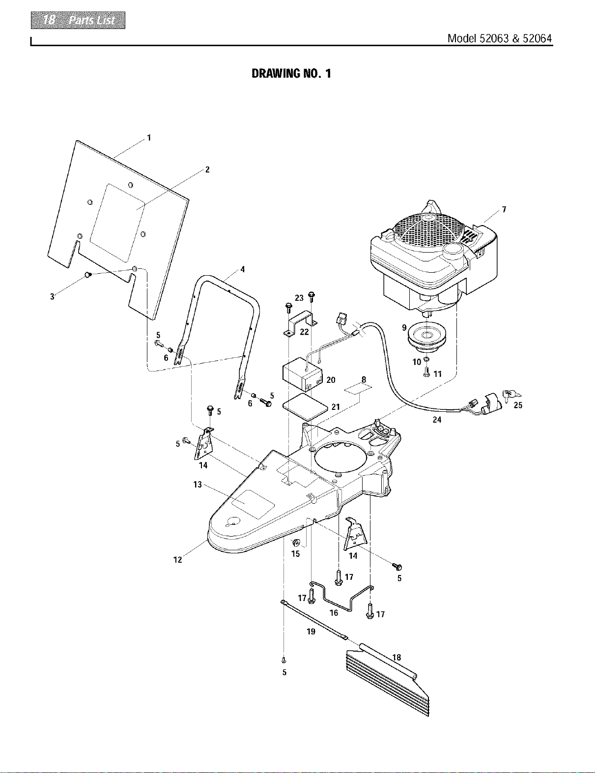
DRAWING NO. 1
24
25
17_
19
5

Model 52063 & 52064 I
PARTSLIST - DRAWINGNO. 1
Ref. # Part# Description Qty, Ref. # Part# Description
Qty.
1 1917765
2 1918082
1904401
3 1915290
4 1917407001
5 1754128
6 1915320
7
8 1904511
9 1917728
10 1100243
11 1100000
12 1918228
(A) Model 52064
(B) Model 52063
Debris Guard ............................................ 1
Decal-Logo (B) ......................................... 1
Decal-Logo (A) ......................................... 1
Push-in Fastener....................................... 5
Debris Guard Support ............................... 1
Hex FlangeScrew,1/4-20 x 3/4................ 8
Spacer...................................................... 2
Engine....................................................... 1
Decal-HotSurfaceWarning ...................... 1
EnginePulley............................................ 1
Spring Lock Washer................................. 1
Hex Hd,Screw, 3/8-24 x 1, Grade5 ......... 1
Deck (Incl. Ref. 13)................................... 1
13 1918115
14 1917144001
15 1186389
16 1917574
17 1768194
18 1917154
19 1917155
20 1909647
21 1915268
22 1915204001
23 90063
24 1918055
25 96520
Decal-Warning.......................................... 1
Hood Bracket............................................ 2
FlangeLock Nut, 1/4-20 ........................... 2
BeltGuide ................................................. 1
HexHd. Screw,3/8-16 x 1-1/2 ................. 3
Deflector Flap............................................ 1
Rod........................................................... 1
Battery(A) ................................................ 1
BatteryPad (A) ......................................... 1
BatteryClamp (A) ..................................... 1
HexFlangeScrew(A), 5/16-18 x 1........... 2
Wire Harness (A)...................................... 1
Ignition Key (A)......................................... 2
Order parts from your local authorizedengine dealer. Referto engine
for model/type number.
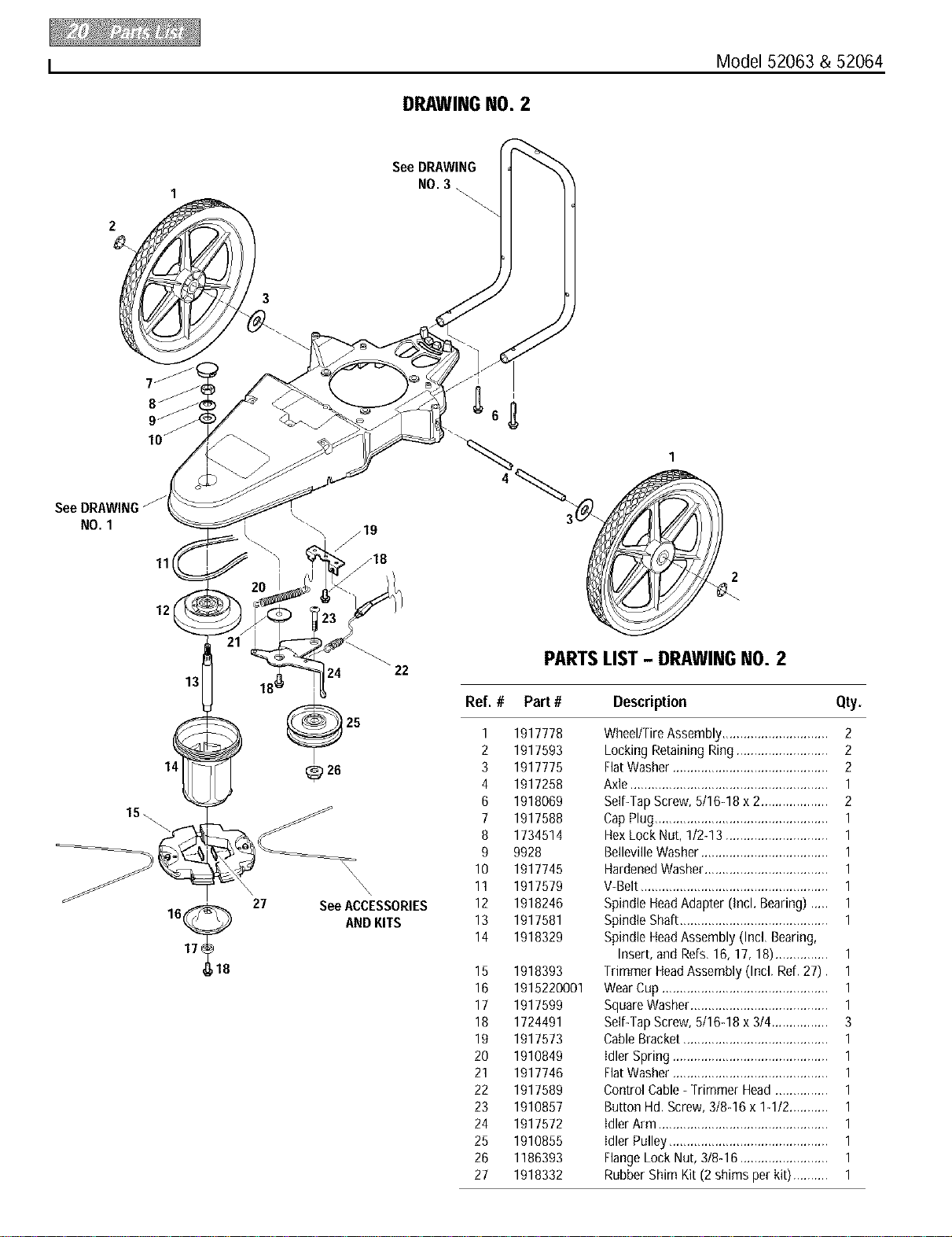
I Model 52063 & 52064
DRAWING NO. 2
See DRAWING
NO. 3 .
NO. 1
11
12
2
15\
13
\
27
17
24 22
25
_26
\\
\\\
See ACCESSORIES
AND KITS
PARTSLIST- DRAWINGNO. 2
Ref. # Part# Description Qty,
1 1917778
2 1917593
3 1917775
4 1917258
6 1918069
7 1917588
8 1734514
9 9928
10 1917745
11 1917579
12 1918246
13 1917581
14 1918329
15 1918393
16 1915220001
17 1917599
18 1724491
19 1917573
20 1910849
21 1917746
22 1917589
23 1910857
24 1917572
25 1910855
26 1186393
27 1918332
Wheel/TireAssembly.............................. 2
Locking Retaining Ring .......................... 2
FlatWasher ............................................ 2
Axle ........................................................ 1
Self-TapScrew, 5/16-18 x 2................... 2
CapPlug................................................. 1
HexLock Nut, 1/2-13 ............................. 1
BellevilleWasher.................................... 1
HardenedWasher................................... 1
V-Belt..................................................... 1
SpindleHeadAdapter (Incl. Bearing)..... 1
SpindleShaft.......................................... 1
SpindleHeadAssembly (Incl, Bearing,
Insert, and Refs,16,17, 18)............... 1
Trimmer HeadAssembly (Incl. Refl27). 1
WearCup ............................................... 1
SquareWasher....................................... 1
Self-TapScrew, 5/16-18 x 3/4 ................ 3
CableBracket......................................... 1
idler Spring ............................................ 1
FlatWasher ............................................ 1
Control Cable- Trimmer Head ............... 1
Button Hd.Screw, 3/8-16 x 1-1/2........... 1
idler Arm ................................................ 1
idler Pulley............................................. 1
FlangeLock Nut, 3/8-16 ......................... 1
Rubber Shim Kit (2 shims per kit).......... 1
Model 52063 & 52064 I
11
PARTSLIST- DRAWINGNO. 3
Ref. # Part# Description Qty.
1 1918283
2 1915889
3 1918304
4 1918070001
5 1917589
6 1908677
7 1749977001
8 1983658
9 1185814
10 1918081
11 1100807
12 1110106
13 1763682
14 1100799
15 1917145001
16 1732499
UpperHandlebar (Incl, Refs,2 & 3) ....... 1
Decal-Bail Engage/Disengage................ 1
Decal-Throttle ....................................... 1
Control Bail-Trimmer Head ................... 1
CableAssembly-Trimmer Head............. 1
Bushing.................................................. 2
CableBracket ......................................... 1
HexHd, Screw,1/4-20 x 1-1/8............... 1
HexFlangeLock Nut, 1/4-20 .................. 1
Throttle Lever & CableAssembly ........... 1
HexHd, Screw,1/4-20 x 2 ..................... 1
HexLock Nut, 1/4-20 ............................. 1
CableTie................................................. 3
HexHd, Screw,5/16-18 x 1-1/2 ............. 2
HandlebarSupport ................................ 1
HexLock Nut, 5/16-18 ........................... 2
16
15
_'_13
ACCESSORIESANDKITS
Ref. # Part # Description Qty.
1 1904476 Trimmer String Kit, ,155"diameter line
(24 pieces) ........................................... Nil
2 1904477 Trimmer String Kit, ,130"diameter line
(24 pieces) ........................................... Nil
3 1768449 BatteryCharger(for electric start model), 1
Nil Not includedwith unit, order separately.

CUSTOMERSERVICEINFORMATION
OwnerRegistration Card
Pleasefill out and mailthe enclosedowner
registration card, The purposeof this cardis
to register eachunit at the factory sothat we
can provide you with warranty benefitsand
informational bulletins.
WarrantyService
Thewarranty statement is included in the unit's literature
package.
Model/SerialNumbers
A Model/Serial Numbersdecalislocatedon the side of the
deck, Forreadyreference,record these numbers inthe
spacesbelow.
Dateof Purchase:
Model Number:
Serial Number:
AuthorizedDealerInformation
If you purchasedyour unit from an authorized dealer,record
the dealer'saddress and phone number belowfor ready refer-
ence:
DealerName:
Address:
Phone:
IMPORTANT:
Leftand rightsidesofthe unitare determinedbystanding
behindtheunit, in theoperator'sposition,andfacing in the
directionofforward travel.
NOTICE:
We reservethe rightto changespecifications,add
improvementsordiscontinuethe manufactureofanyof our
equipmentwithoutnoticeor obligationtopurchasersofour
equipment.
CustomerServiceandTechnical Service
Ifyou havequestionsor problems with the
unit, contact your localdealer or the factory.
(Whencalling or writing, providethe
Model/Serial Numbersof the unit.)
ReplacementParts
Factoryspecified replacementparts are
availablefrom your authorizeddealer or
directly from the factory. Whenordering
parts, be sureto provide thefollowing:
• Model/Serial Numbersof the unit.
• Partnumber of the partneeded.
• Part Description.
• Quantityneeded.
NOTE:All replacementparts must conform to our rigid quality
specifications. Although some replacementparts we provide
may vary slightly in shape,color or texture from the original
parts, anyvariations will not affect the fit or performanceof
these parts on your unit.
EngineServiceand Repair
Forengine serviceor repair, contactyour ......... _..
nearestauthorized enginedealer (look in the ......
Yellow Pagesunder "Engines-Gasoline").
Theengine iswarranted bythe engineman-
ufacturer. Any unauthorizedwork performed ..................................
on the engine during the warranty period
may void this warranty. Eorcomplete
details on the enginewarranty, refer to the
EngineOwner's Manual.
We urge using only genuine replacement parts, which
meet all the latest requirements. Replacement parts
manufactured by others could present safety hazards,
even thoughthey may fit on the unit.
Forcustomerassistance,contactyournearest authorizeddealer or:
GARDEN WAY INCORPORATED • 1 GardenWay • Troy,NewYork 12180
CustomerService:1-800-437-8686 • TechnicalService:1-800-520-5520 • PartsService:1-800-648-6776
• IAX: (518)233-4622 • WEBSITE:www.troybilt.com
Outsidethe UnitedStatesand Canada:
CustomerService:(518) 233-4807 • TechnicalService:(518)233-4808 • PartsService:(518) 233-4806 • FAX(518)233-4622
1905693 (5/01) Printed in U.S.A. _-_2001 GardenWay incorporated

