Loading ...
Loading ...
Loading ...
ASSEMBL Y INSTRUCTIONS .......................I
Items Needed for Assembly
16 oz. of Sears compressor oil, Sears 9-16426 or
SAE 20-20W (Grade SF)
pipe thread sealant
• a9/16" socket or open-end wrench for attaching the
wheels
, a 7/16" open-end wrench for attaching the foot ex-
tension bracket and air pressure gauge
. a 1/4" open-end wrench to tighten handle set screw
, an adjustable wrench for attaching the shut-off valve,air
outlet adapter and pressure regulator.
Installing Handle
THE WHEELS AND HANDLE DO NOT PRO-
VIDE ADEQUATE CLEARANCE, STABIL-
ITY OR SUPPORT FOR PULLING THE UNIT
UP AND DOWN STAIRS OR STEPS. THE
UNIT MUST BE LIFTED OR PUSHED UP A
RAMP. DO NOT LIFT THE UNIT BY THE
MANIFOLD ASSEMBLY. THE UNIT CAN
BE DAMAGED.
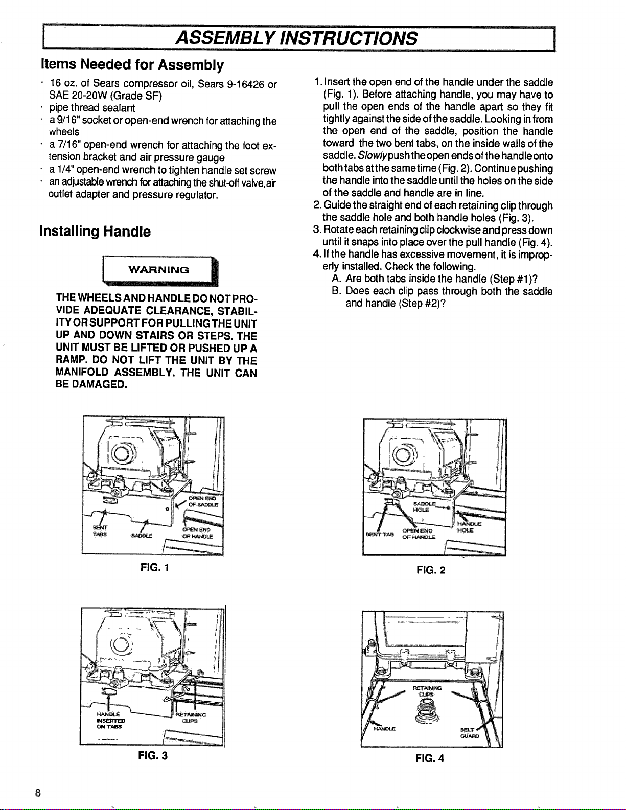
1. Insert the open end of the handle under the saddle
(Fig. 1). Before attaching handle, you may have to
pull the open ends of the handle apart so they fit
tightly against the side of the saddle. Looking in from
the open end of the saddle, position the handle
toward the two bent tabs, on the inside walls of the
saddle. Slowlypushtheopen ends of the handle onto
both tabs atthe sametime (Fig. 2). Continue pushing
the handle into the saddle until the holes on the side
of the saddle and handle are in line.
2. Guide the straight end of each retaining clip through
the saddle hole and both handle holes (Fig. 3).
3. Rotate each retaining clip clockwise and press down
until it snaps into place over the pull handle (Fig. 4).
4. If the handle has excessive movement, it is improp-
erly installed. Check the following.
A. Are both tabs inside the handle (Step #1)?
B. Does each clip pass through both the saddle
and handle (Step #2)?
O
FIG. 1
FIG. 2
"-d.m ........... I_3
IMSIN1NI"I_D
I_1 TABS
FIG. 3
! T
,t ,t
FIG. 4
Loading ...
Loading ...
Loading ...