S _AIRS
CRAFTSMAN
NOTE: For identificationof Repair
Parts, see separate Parts List
Manual.
IMPORTANT:
Read the Safety Guidelines
and All Instructions
Carefully Before Operating
GENERAL MANUAL FOR
OIL LUBRICATED
SINGLE STAGE
AIR COMPRESSORS
SAFETY GUIDELINES
ASSEMBLY
OPERATION
MAINTENANCE
TROUBLESHOOTING
REPAIR PARTS
Record in the spaces provided.
(1) The model number which can be
found on the maintenance label on
the left front of the air tank.
(2) The code number which can be
found on the foil label on the rear
of the air tank.
(3) The Manufacturers Number(ASME
code compressors only) islocated
on the metal data plate which is
welded ontothe backsideofthe air
tank. (This data plate Ispaintedthe
same color as the tank.)
Retain these numbers for future
reference.
Model No.
Code No.
Mfg. No.
i MG-OILLUBE 8/22/90 i
Sears, Roebuck and Co., Chicago, IL 60684 U.S.A.
TABLE OF CONTENTS
Page
WARRANTY .................................................... 2
SAFETY GUIDELINES ................................... 3
WARNING CHART .......................................... 3
SPECIFICATIONS ............................................. 5
GLOSSARY ............................................................. 5
ACCESSORIES FOR USE WITH
SEARS AIR COMPRESSORS ................... 6
GENERAL INFORMATION ............................ 6
ON-RECEIPT INSPECTION ........................... 6
DESCRIPTION OF OPERATION ................... 7
ASSEMBLY ................................................ 8
Items Needed for Assembly ...................... 8
InstallingHandle ........................................ 8
InstallingRubber Foot Strip and Wheels .... 9
InstallingTank Pressure Gauge ................ 9
InstallingRegulator
(for outfits supplied with regulators) ............ 9
Installing Shut-Off Valve
(outfits without regulators) .......................... 9
INSTALLATION AND
BREAK-IN PROCEDURES ............................ 10
Location of Air Compressor ................................ 10
Voltage and Circuit Protection ...................... 10
Extension Cords ................................................ 10
Lubrication and Oil ............................. ........... 10
Page
Grounding Instructions ................................ 10
Piping ........................................................ 11
Additional Regulators and Controls ............ 11
Break-in Procedures .................................. 12
OPERATING PROCEDURES ........................ 12
Daily Start-Up Checklist ................................ 12
Normal Operation ......................................... 13
MAINTENANCE .............................................. 14
SERVICE INSTRUCTIONS ............................. 15
Air Filter- Inspection and Replacement ...... 15
Oil- Checking and Changing ...................... 15
Check Valve - Inspection and Replacement 15
Safety Valve - Inspection and Replacement 15
Belt Replacement ...................................... 16
Belt Guard - Removal and Installation ........ 16
Pressure Switch - Replacement .................. 16
Motor Overload Protector - Reset .............. 17
Motor Lubrication ........................................ 17
Motor - Replacement .................................. 17
Air Compressor Pump - Replacement ........ 17
Pulley and Flywheel - Alignment ................ 18
Manifold/Regulator Assembly -
Removal and Installation ............................ 18
Separate Regulator or Shut-Off Valve -
Replacement .............................................. 18
Servicing Intake and Exhaust Valves .......... 18
STORAGE ........................................................ 19
TROUBLESHOOTING GUIDE ..................... 20
HOW TO ORDER REPAIR PARTS ................. 24
FULL ONE YEAR WARRANTY ON AIR COMPRESSORS
Ifthis air compressor fails dueto adefect inmaterial or workmanship within one yearfrom the date of purchase, RETURN
IT TO THE NEAREST SEARS SERVICE CENTER/DEPARTMENT THROUGHOUT THE UNITED STATES AND
SEARS WILL REPAIR IT, FREE OF CHARGE.
Ifthis aircompressoris usedfor commercial or rental purposes, the warranty willapplyfor ninetydays from the date of
purchase.
This warranty gives you specific legal rights and you may have other rights which vary from state to state.
Sears, Roebuck and Co., Sears Tower, Dept. 731CR-W, Chicago, IL 60684
2
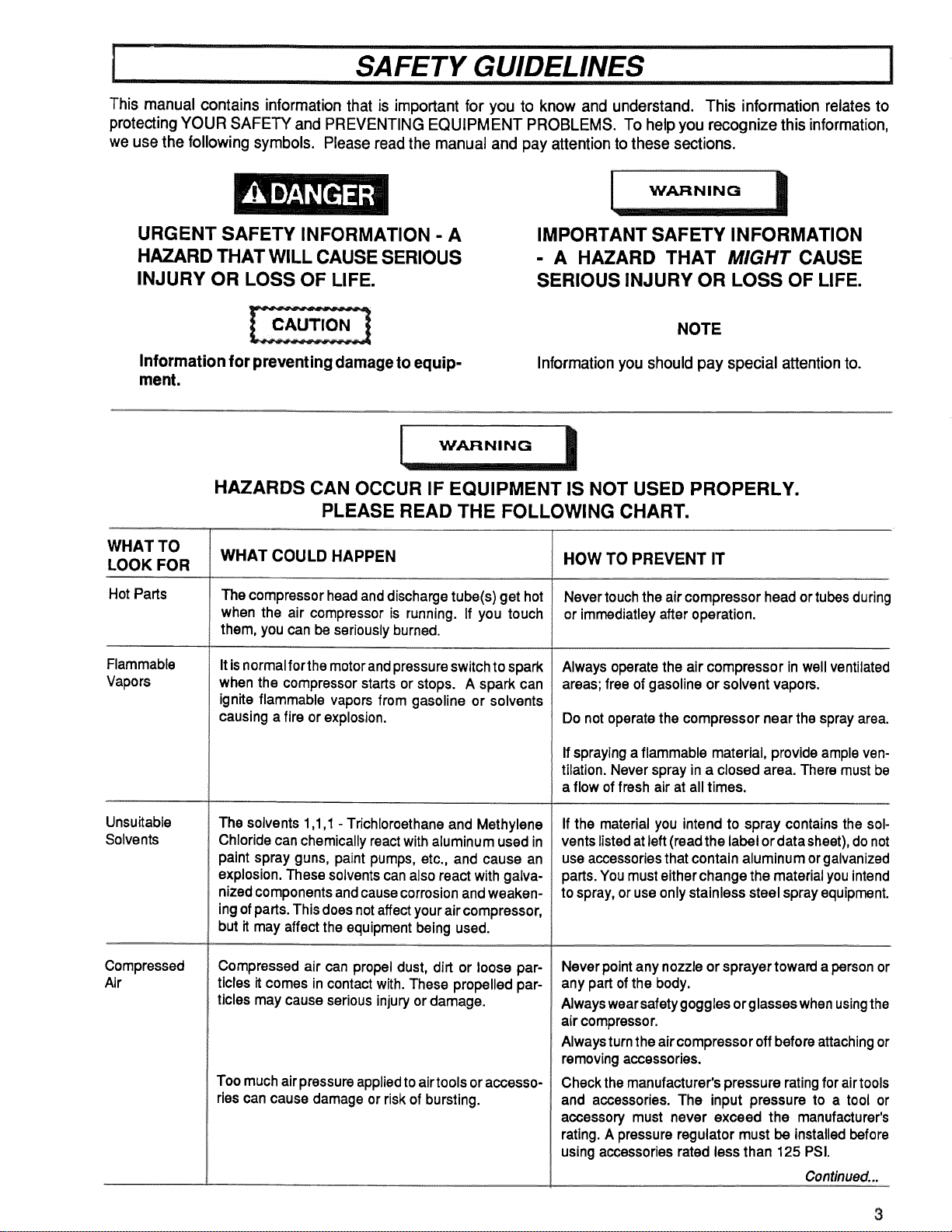
Thismanualcontainsinformationthatisimportantforyouto knowandunderstand.Thisinformationrelatesto
protectingYOURSAFETYandPREVENTINGEQUIPMENTPROBLEMS.Tohelpyourecognizethisinformation,
weusethefollowingsymbols.Pleasereadthemanualandpayattentiontothesesections.
URGENT SAFETY INFORMATION - A
HAZARD THAT WILL CAUSE SERIOUS
INJURY OR LOSS OF LIFE,
IMPORTANT SAFETY INFORMATION
- A HAZARD THAT MIGHT CAUSE
SERIOUS INJURY OR LOSS OF LIFE.
Information for preventing damage to equip-
ment.
NOTE
Information you should pay special attention to.
WHAT TO
LOOK FOR
Hot Parts
Flammable
Vapors
Unsuitable
Solvents
Compressed
Air
i ................
HAZARDS CAN OCCUR IF EQUIPMENT IS NOT USED PROPERLY.
PLEASE READ THE FOLLOWING CHART,
WHAT COULD HAPPEN
The compressorhead anddischarge tube(s)get hot
when the air compressor is running. If you touch
them, youcanbeseriouslyburned.
It isnormalforthe motorandpressure switch to spark
when the compressor starts or stops. A spark can
ignite flammable vapors from gasoline or solvents
causing a fire or explosion.
The solvents 1,1,1 -Trichloroethane and Methylene
Chloride can chemically reactwith aluminum used in
paint spray guns, paint pumps,etc., and cause an
explosion. These solvents can also react with galva-
nized components and causecorrosion andweaken-
ing ofparts. This doesnotaffect yourair compressor,
but it may affect the equipment being used.
Compressed air can propel dust, dirt or loose par-
ticles it comes in contact with. These propelled par-
ticles may cause serious injury or damage.
Toomuch air pressure appliedto airtoolsoraccesso-
riescancause damageor riskofbursting.
HOW TO PREVENT IT
Nevertouch the aircompressorhead ortubesduring
or immediatleyafter operation.
Alwaysoperatethe air compressorin wellventilated
areas;free ofgasolineor solventvapors.
Do notoperatethe compressornearthe sprayarea.
Ifspraying a flammable material, provide ample ven-
tilation. Never spray in a closed area. There must be
a flow of fresh air at all times.
If the material you intend to spray contains the sol-
ventslisted atleft (read the label or data sheet),do not
use accessoriesthat contain aluminum or galvanized
parts.You must eitherchange the material youintend
to spray,or use only stainless steel spray equipment.
Never pointanynozzle orsprayertoward a person or
any part of the body.
Alwayswearsafety goggles or glasses whenusingthe
air compressor.
Always turnthe air compressor off before attachingor
removing accessories.
Checkthe manufacturer's pressure ratingfor airtools
and accessories. The input pressure to a tool or
accessory must never exceed the manufacturer's
rating. A pressure regulator must be installedbefore
using accessories rated less than 125 PSI.
Continued...
3
WHAT TO
LOOK FOR
Electricity
MovingParts
Toxic Vapors
Air Tank
SAFETY GUIDELINES
WHAT COULD HAPPEN
Your air compressor is powered by electricity. Like
any other electrically powered device, if it is not used
properly it may cause electrical shock.
This compressorcyclesautomaticallywhen thepres-
sureswitchisintheON/AUTOposition.Ifyouattempt
repairormaintenancewhilethecompressorisoperat-
ing,or withtheswitchinthe ON/AUTO position,you
can expose yourself to moving parts. These moving
parts cancause serious injuryor damage ifthey come
into contact with you or your clothing.
itisnormalfor compressedair tocontaintoxicor irri-
tating vapors. Such vapors are harmful if inhaled.
Certain materials you are spraying (like paint, weed
killer, sand or insecticide) can be harmful if you inhale
them.
Modifications to the air compressor in an attempt to
reach higher air pressure can cause the air tank to
rupture or explode.
Changing theairtank willcauseittoweaken.Thetank
can rupture or explode.
HOW TO PREVENTIT
I
Wiring of the pressure switch,motor and ON/OFF
switch shouldbe done by a licensed electrician in
accordancewithnationaland local codes.
Always unplug the air compressor prior to mainte-
nance or repair.
Never use the air compressoroutdoors when it is
raining.
Always plug thecordintoan electrical outletwiththe
specified voltage and adequate fuse protection.
Never operatethe compressorwith the belt guard
removed.
Always unplugthe unitand release air pressure from
the tank and any accessories before doing repair or
maintenance.
Never directly inhalethecompressedair producedby
this unit.
Read labels and safety data for all materials you
spray. Follow all safety precautions.
Usea maskor respiratorifthere isachance ofinhaling
toxic sprayed materials. Masks and respirators have
limits and will only provide protection against some
kinds and limited amounts of toxic material. Read
mask and respirator instructions carefully. Consult
with asafety expert or industrial hygienist ifyou arenot
sure about the use of a certain mask or respirator.
Do notadjust, remove or tamperwiththesafetyvalve
or pressure switch. If safety valve or pressure switch
replacement isnecessary, a part with the same pres-
sure rating must be used.
Forservicereplacementuseonlythe motors,pulleys
and belts designed as standard service replacement
parts as indicated in parts list. Use of improper parts
could cause overloading of your unit and electrical
supply.
Do not substitutea gas engine for the motor...the
compressor was not designed to be powered by a
gasoline engine.
Never replacethe compressorpump with a different
model. Never increasethecompressorpump speed.
Neverdrillinto,weldorinanyway modifytheairtank.
Do notrepaira leakingtank;it mustbe replaced.
I SPECIFICATIONS I
Refer to Outfit Parts Bulletin for the specifications of
you rcompressor. Use only afuse or circuit breaker that
isthe same rating asthe branch circuitthe air compres-
sor is operated on. If the compressor is connected to a
circuit protected by fuses, use dual element time delay
fuses, as noted in that service bulletin.
Refer to Outfit Parts Bulletin for your com-
pressor. Certain air compressor models
can be operated on a 15 amp circuit if:
If any of the above conditions cannot be
met, or if operation of the compressor re-
peatedly causes interruption of the power,
it may be necessary to operate it from a 20
amp circuit.
Some models have a dual voltage motor, 120 and 240
volt. They are wired for 120 volt but can be converted
to 240 volt operation. Instructions for connecting these
motors for operation at 240 volt can be found printed on
the inside of the motor covers or on the nameplate of
these motors.
1.Voltage supply to circuit is normal.
2.Circuit is not used to supply any other
electrical needs (lights, appliances, etc.)
3. Extension cords comply with specifica-
tions in this manual.
4.Circuit is equipped with 15 amp circuit
breaker or 15 amp dual element time de-
lay fuse. Use a Fusetron Type "T" time
delay fuse.
Certain air compressor models can be con-
verted to 240 volts from 120 volt operation.
When converting a specific model to 240
volt operation, the attached three-prong 120
volt plug must be replaced with the three-
prong 240 volt plug (purchase locally) or
order line cord Part No. SUDL-404-1.
I
CFM: Cubic feet per minute.
SCFM: Standard cubic feet per minute; a unit of
measure of air delivery.
PSIG: Pounds per square inch gauge; a unit of
measure of pressure.
ASME: American Society of Mechanical Engineers;
made, tested, inspected and registered to meet the
standards of the ASME.
U.L. Listed: Underwriter Laboratories; Samples of
compressor outfits, taken from production, were sub-
mitted to U.L. and found to comply with their require-
ments for design and performance.
Cut-In Pressure: While the motor is off, air tank
pressu redrops as you continueto use your accessory.
When the tank pressure drops to a certain low levelthe
motor will restart automatically. The low pressure at
which the motorautomatically re-starts iscalled "cut-in
pressure."
Cut-Out Pressure: When you turn on your air com-
pressor and itbegins to run, air pressure inthe air tank
begins to build. It builds to a certain high pressure
before the motor automatically shuts off - protecting
your air tank from pressure higher than its capacity.
The highpressure atwhich the motor shutsoff iscalled
"cut-out pressure."
Thefollowingaccessoriesareavailablethroughthecurrentgeneralsalecatalogoratfull-lineSearsstores.
•SPRAY GUNS
•BLOW GUNS
•AIR CAULKING GUNS
•AIR POWERED WASHER GUNS
"SANDBLASTERS
•AIR BRUSHES
•AIR LINE FILTERS
•TIRE AIR CHUCKS
•PAINT TANKS
•AIR TANKS
•INFLATOR KITS
•QUICK CONNECTOR SETS
(various sizes)
.VlSCOSIMETER
•AIR PRESSURE REGULATORS
•OIL FOG LUBRICATORS
•AIR TOOLS:
Sanders
Drills
Impact Wrenches
Hammers
•AIR HOSE:
1/4", 5/16" or 3/8" I.D.
in various lengths
.NAILER/STAPLERS
Decking Finishing
Farming Carpenting
Roofing Upholstery
Siding Picture Framing
•DRAIN CLEANER
•DUSTER GUN
i
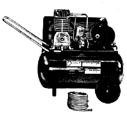
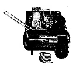
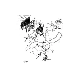
You have purchased an air compressor unit consisting
of a 2 cylinder, single-stage air compressor pump, an
air tank, air hose, wheels, handle, associated controls
and instruments. You may also find an air chuck.
GENERAL INFORMATION
_n_iine_u_r_catoris usu
prolong tool life.
Your air compressor can be used for operating paint
spray guns, air tools, caulking guns, grease guns, air
brushes, sandblasters, inflating tires and plastic toys,
spraying weed killers, insecticides, etc. An air pressure
regulator is recommended for most of these applica-
tions.
Separate air transformers which combine the functions
of air regulation and/or moisture and dirt removal
should be used where applicable.
These accessories can be purchased from most Sears
stores or from the Sears General or Power Tool
Catalog.
An air line filter is usually required for removal of
moisture and oil vapor in compressed air when a paint
spray gun is used.
i ON-RECE PTINSPECT ON I
Each air compressor outfit is carefully checked before
shipment. With improper handling, damage may result
in transit and cause problems in compressor opera-
tion, a bent crankshaft, etc.
Immediately upon arrival, check equipment for both
concealed and visible damages to avoid expenses
being incurred to correct such problems. This should
be done regardless of any visible signs of damage to
the shipping container. Report any damages to carrier
and arrange for inspection of goods immediately.
DESCR PT ONOFOPERAT ON!
L , i
Drain Valve: At the base of the air tank to drain con-
densation at the end of each use.
Shut-off Valve: Turn the knob counterclockwise to
open the valve and clockwise to close.
Motor Thermal Overload Protector: The electric
motor has an automatic thermal overload protector. If
the motor overheats for any reason, thethermal over-
load protector willshut offthe motor. The motor must
be allowed to cool down before restarting.
Safety Valve: If the pressure switch does not shut off
the air compressor at itscut-out pressure setting,the
safety valve will protect against high pressure by
"popping out" at itsfactory set pressure (slightlyhigher
than the pressure switch cut-out setting).
ON/AUTO - OFF Switch: Turn this switch ON to
provide automatic power to the pressure switch and
OFF to remove power.
Air Intake Filter: This filter is designed to clean air
coming intothe pump. Thisfilter must always be clean
and ventilation openings free from obstructions. See
"Maintenance".
Air Compressor Pump: To compress air, the piston
moves up and down in the cylinder. On the down-
stroke, air isdrawn inthrough theair intake valves. The
exhaust valve remains closed. On the upstroke of the
piston, air iscompressed. The intake valves close and
compressed air is forced out through the exhaust
valve, through the outlettube, throughthe check valve
and into the air tank. Working air isnot available until
the compressor hasraised the airtank pressure above
that required at the air outlet.
Check Valve: When the air compressor is operating,
the check valve is "open", allowing compressed air to
enter the air tank. When the air compressor reaches
"cut-out" pressure, the check valve "closes", allowing
air pressure to remain inside the air tank.
Pressure Release Valve: The pressure release valve
located on the side ofthe pressure switch, isdesigned
toautomatically release compressed air from the com-
pressor head and the outlettube when the aircompres-
sor reaches "cut-out" pressure or isshut off. Ifthe air
is not released, the motor will try to start, but will be
unableto. The pressure release valve allowsthe motor
to restart freely. When the motorstops running, air will
be heard escaping from the valve for a few seconds.
No air should be heard leaking when the motor is
running.
Pressure Switch: The pressure switch automatically
starts the motor when the air tank pressure drops
below the factory set "cut-in" pressure. It stops the
motor when the air tank pressure reaches the factory
set "cut-out" pressure.
Regulator: The air pressure coming from the air tank
is controlled by the regulator knob. Turn the knob
clockwiseto increase pressure and counter-clockwise
to decrease pressure. To avoid minor readjustment
after making a change in pressure setting, always
approach the desired pressure from a lower pressure.
When reducing from a higher to a lower setting, first
reduce to some pressure less than that desired, then
bringup tothe desired pressure. Depending onthe air
requirements of each particular accessory, the outlet
regulated air pressure may have to be adjusted while
operating the accessory.
Outlet Pressure Gauge: The outlet pressure gauge
indicatesthe airpressure available at the outlet sideof
the regulator. This pressure is controlled by the
regulator and is always less or equal to the tank
pressure. See "Operating Procedures".
Tank Pressure Gauge: The tank pressure gauge in-
dicates the reserve air pressure in the tank. On outfits
with no pressure regulator, this is also the pressure
available at the air outlet.
Regulator: The air pressure coming from the air tank
is controlled by the regulator knob. Turn the knob
clockwise to increase pressure and counterclockwise
to decrease pressure. To avoid minor readjustment
after making a change in pressure setting, always
approach the desired pressure from a lower pressure.
When reducing from a higher to a lower setting, first
reduce to some pressure less than that desired, then
bringup to the desired pressure. Depending on the air
requirements of each particular accessory, the outlet
regulated air pressure may have to be adjusted while
you are operating the accessory. Some models have
shut-off valves only and do not include regulators.
ASSEMBL Y INSTRUCTIONS .......................I
Items Needed for Assembly
16 oz. of Sears compressor oil, Sears 9-16426 or
SAE 20-20W (Grade SF)
pipe thread sealant
• a9/16" socket or open-end wrench for attaching the
wheels
, a 7/16" open-end wrench for attaching the foot ex-
tension bracket and air pressure gauge
. a 1/4" open-end wrench to tighten handle set screw
, an adjustable wrench for attaching the shut-off valve,air
outlet adapter and pressure regulator.
Installing Handle
THE WHEELS AND HANDLE DO NOT PRO-
VIDE ADEQUATE CLEARANCE, STABIL-
ITY OR SUPPORT FOR PULLING THE UNIT
UP AND DOWN STAIRS OR STEPS. THE
UNIT MUST BE LIFTED OR PUSHED UP A
RAMP. DO NOT LIFT THE UNIT BY THE
MANIFOLD ASSEMBLY. THE UNIT CAN
BE DAMAGED.
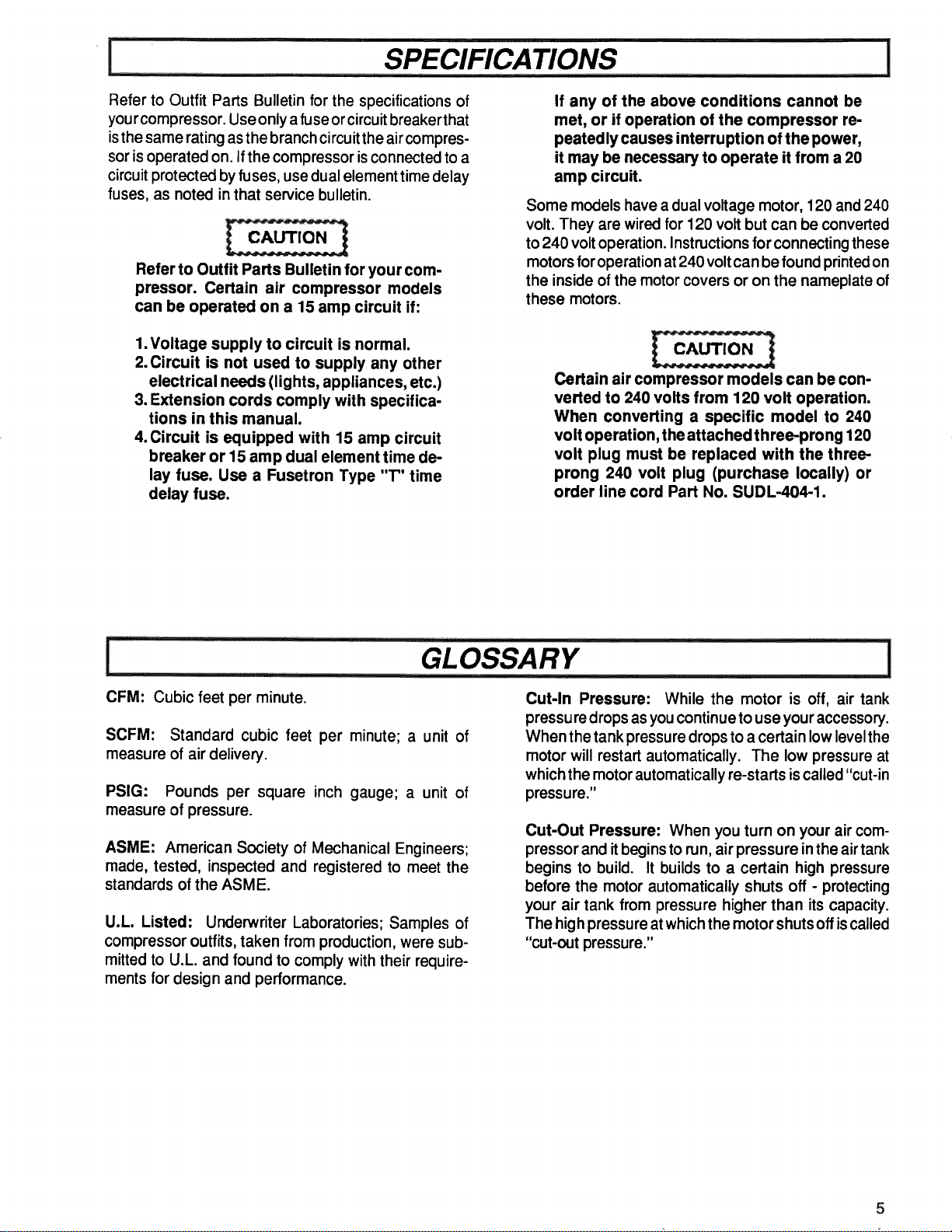
1. Insert the open end of the handle under the saddle
(Fig. 1). Before attaching handle, you may have to
pull the open ends of the handle apart so they fit
tightly against the side of the saddle. Looking in from
the open end of the saddle, position the handle
toward the two bent tabs, on the inside walls of the
saddle. Slowlypushtheopen ends of the handle onto
both tabs atthe sametime (Fig. 2). Continue pushing
the handle into the saddle until the holes on the side
of the saddle and handle are in line.
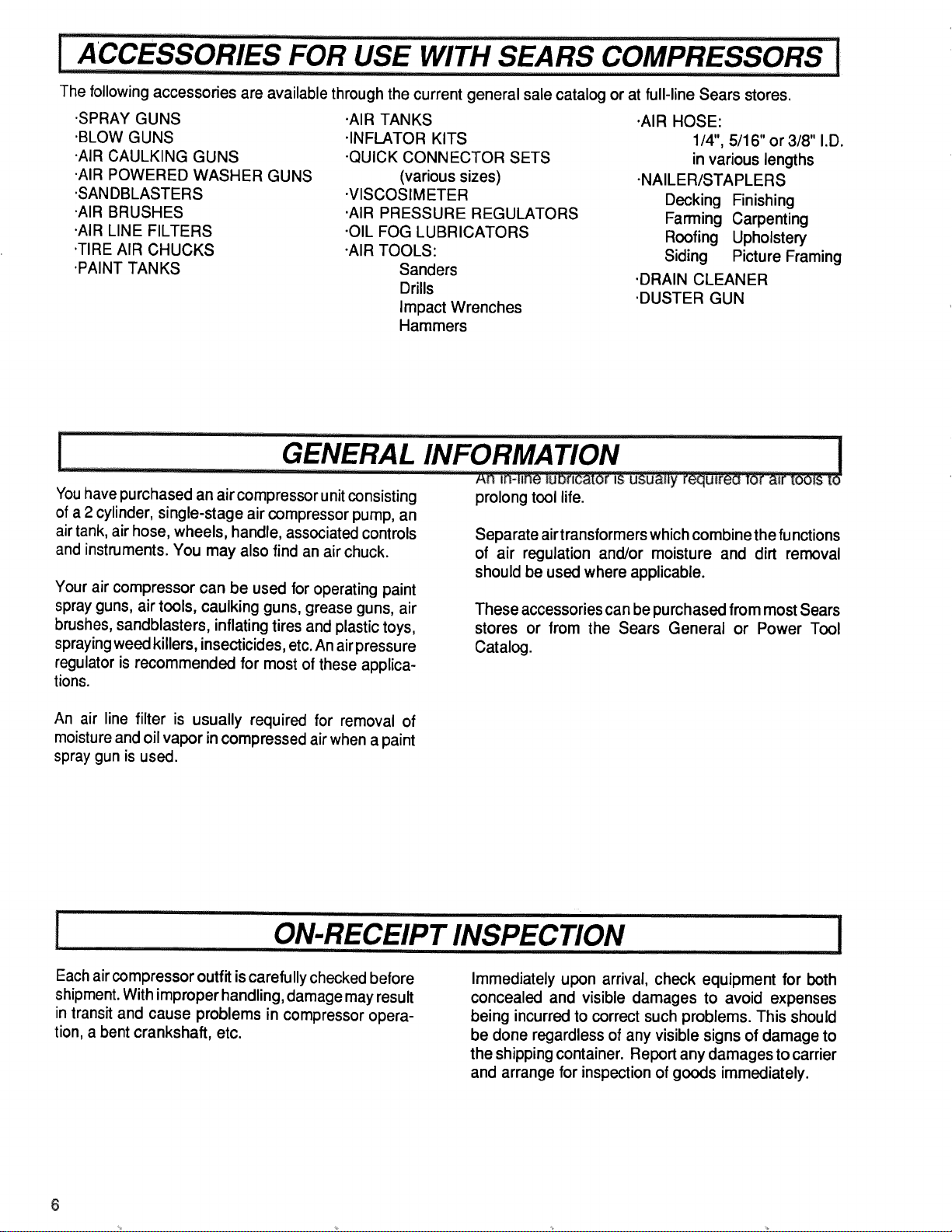
2. Guide the straight end of each retaining clip through
the saddle hole and both handle holes (Fig. 3).
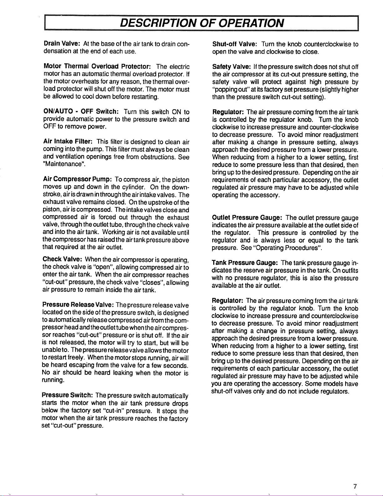
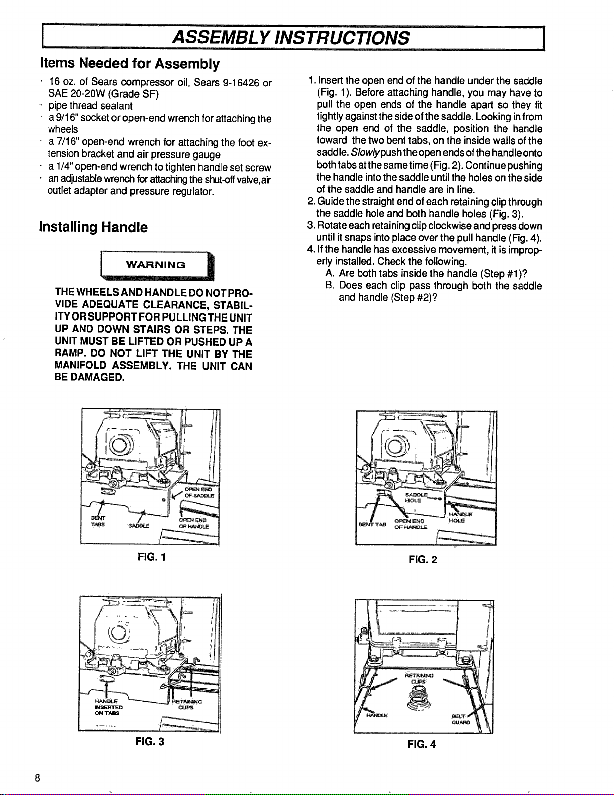
3. Rotate each retaining clip clockwise and press down
until it snaps into place over the pull handle (Fig. 4).
4. If the handle has excessive movement, it is improp-
erly installed. Check the following.
A. Are both tabs inside the handle (Step #1)?
B. Does each clip pass through both the saddle
and handle (Step #2)?
O
FIG. 1
FIG. 2
"-d.m ........... I_3
IMSIN1NI"I_D
I_1 TABS
FIG. 3
! T
,t ,t
FIG. 4
............. ASSEMBL Y INSTRUCTIONS I
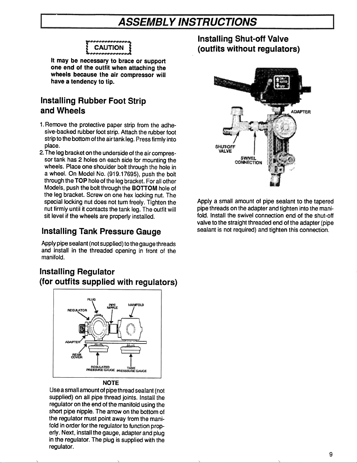
It may be necessary to brace or support
one end of the outfit when attaching the
wheels because the air compressor will
have a tendency to tip.
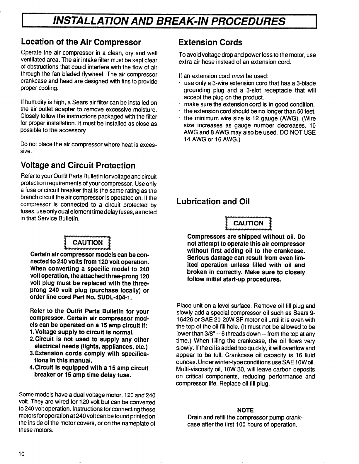
Installing Shut-off Valve
(outfits without regulators)
Installing Rubber Foot Strip
and Wheels
1.Remove the protective paper strip from the adhe-
sive-backed rubber foot strip. Attach the rubber foot
strip to the bottom of the air tank leg. Press firmly into
place.
2.The leg bracket on the underside of the air compres-
sor tank has 2 holes on each side for mounting the
wheels. Place one shoulder bolt through the hole in
a wheel. On Model No. (919.17695), push the bolt
through the TOP hole of the leg bracket. For all other
Models, push the bolt through the BOTTOM hole of
the leg bracket. Screw on one hex locking nut. The
special locking nut does not turnfreely. Tighten the
nut firmly until itcontacts the tank leg. The outfitwill
sitlevel ifthe wheels are properly installed.
Installing Tank Pressure Gauge
Applypipe sealant (not supplied) tothe gauge threads
and install in the threaded opening in front of the
manifold.
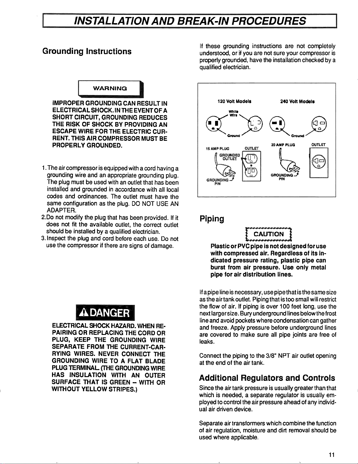
Installing Regulator
(for outfits supplied with regulators)
Apply a small amount of pipe sealant to the tapered
pipe threads on the adapter and tighten into the mani-
fold. Install the swivel connection end of the shut-off
valve to the straight threaded end of the adapter (pipe
sealant is not required) and tighten this connection.
M_
NOTE
Use a small amount ofpipe thread sealant (not
supplied) on all pipe thread joints. Install the
regulator on the end of the manifoldusing the
short pipe nipple. The arrow on the bottom of
the regulator must point away from the mani-
fold inorder for the regulator to function prop-
erly. Next, installthe gauge, adapter and plug
in the regulator. The plug is supplied with the
regulator.
i INSTALLATION AND BREAK-IN PROCEDURES I
Location of the Air Compressor
Operate the air compressor in a clean, dry and well
ventilated area. The air intake filter mustbe kept clear
of obstructionsthat could interfere with the flow of air
through the fan bladed flywheel. The air compressor
crankcase and head are designed with fins to provide
proper cooling.
if humidity is high, a Sears air filter can be installed on
the air outlet adapter to remove excessive moisture.
Closely follow the instructions packaged with the filter
for proper installation. It must be installed as close as
possible to the accessory.
Do not place the air compressor where heat is exces-
sive.
Extension Cords
To avoid voltage dropand power loss tothe motor,use
extra air hose instead of an extension cord.
If
an extension cord must be used:
use only a 3-wire extension cord that has a 3-blade
grounding plug and a 3-slot receptacle that will
accept the plug on the product.
make sure the extension cord is in good condition.
the extension cord should be no longer than 50 feet.
the minimum wire size is 12 gauge (AWG). (Wire
size increases as gauge number decreases. 10
AWG and 8 AWG may also be used. DO NOT USE
14 AWG or 16 AWG.)
Voltage and Circuit Protection
Refer to your Outfit Parts Bulletin for voltage and circuit
protection requirements of your compressor. Use only
a fuse or circuit breaker that is the same rating as the
branch circuit the air compressor is operated on. If the
compressor is connected to a circuit protected by
fuses, use only dual element time delay fuses, as noted
in that Service Bulletin.
Lubrication and Oil
Certain air compressor models can be con-
nected to 240 volts from 120 volt operation.
When converting a specific model to 240
volt operation, the attached three-prong 120
volt plug must be replaced with the three-
prong 240 volt plug (purchase locally) or
order line cord Part No. SUDL-404-1.
Refer to the Outfit Parts Bulletin for your
compressor. Certain air compressor mod-
els can be operated on a 15 amp circuit if:
1.Voltage supply to circuit is normal.
2. Circuit is not used to supply any other
electrical needs (lights, appliances, etc.)
3.Extension cords comply with specifica-
tions in this manual.
4.Circuit is equipped with a 15 amp circuit
breaker or 15 amp time delay fuse.
Some models have a dual voltage motor, 120 and 240
volt.They are wired for 120 volt but can be converted
to 240 volt operation. Instructions for connecting these
motors for operation at 240 volt can be found printed on
the inside of the motor covers, or on the nameplate of
these motors•
Compressors are shipped without oil. Do
not attempt to operate this air compressor
without first adding oil to the crankcase.
Serious damage can result from even lim-
ited operation unless filled with oil and
broken in correctly. Make sure to closely
follow initial start-up procedures.
Place unit on a level surface. Remove oil fill plug and
slowly add a special compressor oil such as Sears 9-
16426 or SAE 20-20W SF motor oil until it is even with
the top of the oil fill hole. (It must not be allowed to be
lower than 3/8" -- 6 threads down -- from the top at any
time.) When filling the crankcase, the oil flows very
slowly. If the oil is added too quickly, it will overflow and
appear to be full. Crankcase oil capacity is 16 fluid
ounces. Under winter-type conditions use SAE 10W oil.
Multi-viscosity oil, 10W 30, will leave carbon deposits
on critical components, reducing performance and
compressor life. Replace oil fill plug.
NOTE
Drain and refillthe compressor pump crank-
case after the first 100 hours of operation.
10
I.... INSTALLATION AND BREAK-IN PROCEDURES !
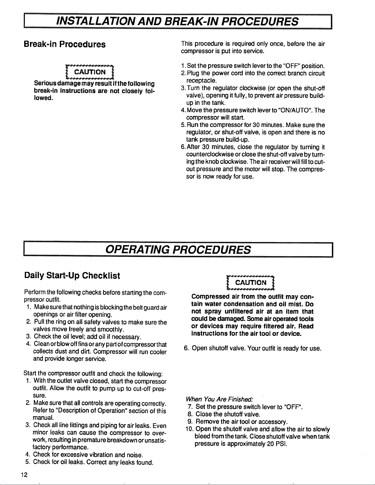
Grounding Instructions
If these grounding instructions are not completely
understood, or if you are not sure your compressor is
properly grounded, have the installation checked by a
qualified electrician.
IMPROPER GROUNDING CAN RESULT IN
ELECTRICAL SHOCK. IN TH EEVENT OF A
SHORT CIRCUIT, GROUNDING REDUCES
THE RISK OF SHOCK BY PROVIDING AN
ESCAPE WIRE FOR THE ELECTRIC CUR-
RENT. THIS AIR COMPRESSOR MUST BE
PROPERLY GROUNDED.
1.The air compressor is equipped with a cord having a
grounding wire and an appropriate grounding plug.
The plug must be used with an outlet that has been
installed and grounded in accordance with all local
codes and ordinances. The outlet must have the
same configuration as the plug. DO NOT USE AN
ADAPTER.
2.Do not modify the plug that has been provided. If it
does not fit the available outlet, the correct outlet
should be installed by a qualified electrician.
3. Inspect the plug and cord before each use. Do not
use the compressor if there are signs of damage.
120 Volt Models
WhltQ
P_N
240 Volt Model=
20 AMP PLUG
GROUNDING -_
PIN
Piping
Plastic or PVC pipe is not designed for use
with compressed air. Regardless of its in-
dicated pressure rating, plastic pipe can
burst from air pressure. Use only metal
pipe for air distribution lines.
ELECTRICAL SHOCK HAZARD. WHEN RE-
PAIRING OR REPLACING THE CORD OR
PLUG, KEEP THE GROUNDING WIRE
SEPARATE FROM THE CURRENT-CAR-
RYING WIRES. NEVER CONNECT THE
GROUNDING WIRE TO A FLAT BLADE
PLUG TERMINAL (THE GROUNDING WIRE
HAS INSULATION WITH AN OUTER
SURFACE THAT IS GREEN - WITH OR
WITHOUT YELLOW STRIPES.)
If apipe line is necessary, use pipe that isthe same size
as the air tank outlet. Piping that istoo small will restrict
the flow of air. If piping is over 100 feet long, use the
next larger size. Bury underground lines belowthe frost
line and avoid pockets where condensation can gather
and freeze. Apply pressure before underground lines
are covered to make sure all pipe joints are free of
leaks.
Connect the piping to the 3/8" NPT air outlet opening
at the end of the air tank.
Additional Regulators and Controls
Since the airtank pressure isusually greater than that
which is needed, a separate regulator is usually em-
ployed to control the air pressure ahead of any individ-
ual air driven device.
Separate air transformers which combine the function
of air regulation, moisture and dirt removal should be
used where applicable.
11
Break-in Procedures
Serious damage may result ifthe following
break-in instructions are not closely fol-
lowed.
This procedure is required only once, before the air
compressor is put into service.
1.Set the pressure switch lever tothe "OFF" position.
2. Plug the power cord into the correct branch circuit
receptacle.
3. Turn the regulator clockwise (or open the shut-off
valve), opening it fully, to prevent air pressure build-
up in the tank.
4. Move the pressure switch lever to "ON/AUTO". The
compressor will start.
5. Run the compressor for 30 minutes. Make sure the
regulator, or shut-off valve, is open and there is no
tank pressure build-up.
6.After 30 minutes, close the regulator by turning it
counterclockwise or close the shut-off valve by turn-
ing the knob clockwise. The air receiver will fill to cut-
out pressure and the motor will stop. The compres-
sor is now ready for use.
OPERATING PROCEDURES ................................................!
Daily Start-Up Checklist
Perform the following checks before starting the com-
pressor outfit.
1. Make sure that nothing isblocking the belt guard air
openings or air filter opening.
2. Pull the ring on all safety valves to make sure the
valves move freely and smoothly.
3. Check the oil level; add oil if necessary.
4. Clean or blow off fins or any part ofcompressor that
collects dust and dirt. Compressor will run cooler
and provide longer service.
Start the compressor outfit and check the following:
1. With the outlet valve closed, start the compressor
outfit. Allow the outfit to pump up to cut-off pres-
sure.
2. Make sure that all controls are operating correctly.
Refer to "Description of Operation" section of this
manual.
3. Check all line fittings and piping for air leaks. Even
minor leaks can cause the compressor to over-
work, resulting in prematu re breakdown or unsatis-
factory performance.
4. Check for excessive vibration and noise.
5. Check for oil leaks. Correct any leaks found.
12
Compressed air from the outfit may con-
tain water condensation and oil mist. Do
not spray unfiltered air at an item that
could be damaged. Some air operated tools
or devices may require filtered air. Read
instructions for the air tool or device.
6. Open shutoff valve. Your outfit is ready for use.
When You Are Finished:
7. Set the pressure switch lever to "OFF".
8. Close the shutoff valve.
9. Remove the air tool or accessory.
10. Open the shutoff valve and allow the air to slowly
bleed from the tank. Close shutoff valve when tank
pressure is approximately 20 PSI.
.............. OPERA TING PROCEDURES ..............................................................................................I
Normal Operation
1. Before attaching an air hose or accessory, make
sure the pressure switch lever is in the "OFF"
position. Close the shut-off valve by turning the
knob clockwise, or close air regulator outlet by
turning it counterclockwise.
2. Attach hose and accessory.
TOO MUCH AIR PRESSURE CAUSES A
HAZARDOUS RISK OF BURSTING. CHECK
THE MANUFACTURER'S MAXIMUM PRES-
SURE RATING FOR AIR TOOLS AND AC-
CESSORIES. THE REGULATOR OUTLET
PRESSURE MUST NEVER EXCEED THE
MAXIMUM PRESSURE RATING. ON MOD-
ELS HAVING ONLY A SHUT-OFF VALVE,
YOU MUST INSTALL A REGULATOR
BEFORE USING ACCESSORIES RATED
AT LESS THAN 125 PSIG.
WATER WILL CONDENSE IN THE AIR TANK.
IF NOT DRAINED, WATER WILL CORRODE
AND WEAKEN AIR TANK, CAUSING A RISK
OF AIR TANK RUPTURE.
4. With tank pressure at approximately 20 PSI, open
the drain cock and allow moisture to drain.
NOTE
If the drain cockvalve isplugged, release all air
pressure. The valve can then be removed,
cleaned and reinstalled.
5. After the water has been drained, close the drain
cock. The air compressor can now be stored.
3. Turn the pressure switch lever to the "ON-AUTO"
position and allow tank pressure to build. The motor
will stop when tank pressure reaches cut-out pres-
sure.
13
MAINTENANCE ............ I
UNIT CYCLES AUTOMATICALLY WHEN POWER IS ON. DURING MAINTE-
NANCE, YOU COULD BE EXPOSED TO VOLTAGE SOURCES, COMPRESSED
AIR OR MOVING PARTS. PERSONAL INJURIES CAN OCCUR. UNPLUG THE
UNIT AND BLEED OFF ALL AIR TANK PRESSURE BEFORE DOING ANY
MAINTENANCE OR REPAIR. NEVER OPERATE THE UNIT WITH THE BELT
GUARD REMOVED.
To ensure efficient operation and longer life of the air compressor outfit, a routine maintenance schedule should be
prepared and followed. The following routine maintenance schedule is geared to an outfit in a normal working
environment operating on a daily basis. If necessary, the schedule should be modified to suit the conditions under
which your compressor is used. The modifications will depend upon the hours of operation and the working
environment. Compressor outfitsin an extremely dirtyand/or hostile environment willrequire a greater frequency of
all maintenance checks. Lubricate compressor motoraccording to manufacturer's instructions,which are attached to
your motor.
Routine Maintenance Schedule
Every 8 Hours of Operation
1. Check oil level. Add if necessary.
2. Drain water from the air tank, any moisture sepa-
ratorsor transformers.
3. Check for any unusual noise and/or vibration.
4. Manually check all safety valves to make sure they
are operating properly.
5. Inspect for oil leaks and repair any leaks found.
Every 160 Hours of Operation
1. Check drive belttension;adjust ifnecessary. (Refer
to SERVICE INSTRUCTIONS in this manual.)
2. Inspect air lines and fittings for leaks; correct as
necessary.
3. Check the alignment ofthe motor pulley to the fly-
wheel. If necessary, align to within 1/32 inch on
centerline.
Every 40 Hours of Operation
1. Clean and inspect the air intake filter; replace if
necesssary.
2. Inspect condition of drive belt; replace if neces-
sary.
Each Year of Operation
or if a Problem is Suspected
Check condition of air compressor pump intake and
exhaust valves. Replace if damaged or worn out.
Every 100 Hours of Operation
1. Drain and refill compressor crankcase with16 fluid
ounces (473.2 ml) of clean oil, Sears 9-16426 or
SAE 20-20W. (Use SAE 10W oilunder winter-type
conditions.)
2. Increase frequency of oil changes if humidity or
operating conditions are extreme.
14
! .... SERWCE NsTRUcT ONs i
Air Filter - Inspection and
Replacement
Check Valve - Inspection and
Replacement
NOTE
Keep the air filter clean at all times. Do not
operate the compressor with the air filter re-
moved.
A dirty air filter will not allow the compressor to operate
atfull capacity. Before you use the compressor, check
the air filter to be sure it is clean.
Ifit isdirty, replace itwith a new filter. On some models,
the filter may be removed by using a pair of needle
nosed pliers or a screwdriver. Pull or pry out the old
filter. Push in the new air filter. Other models require
removal of the belt guard and/or filter retainer.
Remove and inspect the check valve at least once a
year or more often if the compressor is heavily used.
Moisture and other contaminants in the hot com-
pressed air will cause an accumulation of a carbon-like
residue on the working parts. If the valve has heavy
carbon build-up, itshould be replaced. Use the follow-
ing procedure to inspect, clean or replace the check
valve.
1. Unplug compressor. Release air pressure from the
air tank.
2. Loosen the top and bottom tube nuts and remove
the outlet tube.
3. Unscrew the check valve (turn counterclockwise)
using socket wrench (7/8").
4. Check that the valve disc moves freely and that the
spring holds the disc in the upper, closed position.
The check valve may be cleaned with a solvent.
5. Apply sealant to the check valve threads. Reinstall
the check valve (turn clockwise). Do not over-
tighten.
6. Replace the outlet tube and tighten top and bottom
tube nuts.
Oil- Checking and Changing
Safety Valve- Inspection and
Replacement
Overfilling with oil will cause premature
compressor failure. Do not overfill.
Check oil level in the crankcase daily. Remove the oil
fill plug. The oil level should be even with the top of the
fill hole and must not be allowed to be lower than 3/8"
from the top (6 threads) at any time. It is recommended
that the oil be changed after every 100 hours of
operation. To drain the oil, removethe oildrain plug and
collect the oil in a suitable container. Be sure to replace
the plug securely before adding new oil. Use a special
compressor oil such as Sears 9-16426 orSAE 20-20W
SF motor oil. [Crankcase oil capacity is 16 fluid ounces
(473.2 ml).] Under winter-type conditions use SAE
10W.
IF THE SAFETY VALVE DOES NOT WORK
PROPERLY, OVER-PRESSURIZATION MAY
OCCUR, CAUSING AIR TANK RUPTURE
OR EXPLOSION. OCCASIONALLY PULL
THE RING ON THE SAFETY VALVE TO
MAKE SURE THAT THE SAFETY VALVE
OPERATES FREELY. IF THE VALVE IS
STUCK OR DOES NOT OPERATE
SMOOTHLY, IT MUST BE REPLACED WITH
A VALVE HAVING THE SAME PRESSURE
RATING.
15
...... SERVICE INSTRUCTIONS
Belt- Replacement
SERIOUS INJURY OR DAMAGE MAY
OCCUR IF PARTS OF THE BODY OR LOOSE
ITEMS GET CAUGHT IN MOVING PARTS.
NEVER OPERATE THE OUTFIT WITH THE
BELT GUARD REMOVED. THE BELT
GUARD SHOULD BE REMOVED ONLY
WHEN THE COMPRESSOR IS UN-
PLUGGED.
3. Remove belt and replace.
NOTE
The belt must be centered over the grooves
on the flywheel and motor pulley.
4. Replace the front of the belt guard.
Adjust Belt Tension
Adjust belt tension by tightening the wing nut until it
makes contact with the washer, plus one additional
turn.
Belt Guard - Removal and Installation
(Refer to Outfit Parts Bulletin, if required.)
1. Move the "ON/AUTO-OFF" lever to the "OFF" po-
sition. Unplug the compressor. Release all air tank
pressu re.
2. Disconnect the motor cord from the motor. Pull the
cord out, from beneath the saddle, toward the pres-
sure switch.
3. Disconnect the pressure release tube from the
pressure switch. Place a wrench on the release
valve to prevent it from rotating. Place another
wrench on tube nut and unscrew and remove.
4. Using a flat-bladed screwdriver, push down on top
of the manifold tube fitting adapter while pulling up
on the tube. This will disconnect the manifold tube
from the tank fitting.
5. Remove the two beltguard screws on the bottom
front of the outfit.
6. If so equipped, remove inside guard from saddle.
Pressure Switch - Replacement
PRESSURE LOADS BEYOND DESIGN LIM-
ITS MAY CAUSE TANK RUPTURE OR EX-
PLOSION. PRESSURE SWITCH OPERA-
TION IS RELATED TO MOTOR HP, TANK
RATING AND SAFETY VALVE SETrlNG.
DO NOT A'n'EMPT TO ADJUST, REMOVE
OR DEFEAT THE PRESSURE SWITCH, OR
CHANGE AND MODIFY ANY PRESSURE
CONTROL RELATED DEVICE. IF REPLACE-
MENT IS NECESSARY, THE SAME RATED
SWITCH MUST BE USED.
Replace Belt
1. Unplug compressor.
2. Remove the front of the belt guard by disengaging
the snaps. Insert a flat bladed screwdriver at each
snap location and pry the beltguard apart.
NOTE
Forcompressors witha motor hold down plate,
loosenthe wing nutatthe holddown plate. The
motorcan be tiltedtoallowfor easy removal or
installation of the belt.
For compressors with a motor tension spring,
lift motor until belt can be removed or installed.
16
l.............................................Sv.RvlcEluSmucrious............................................I
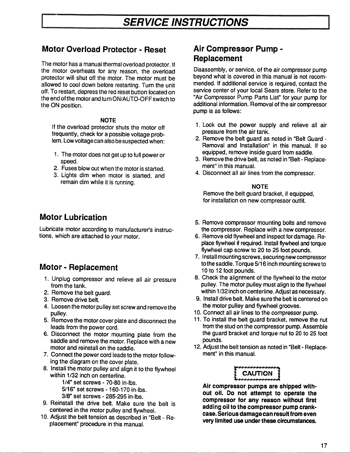
Motor Overload Protector - Reset
The motor has a manual thermal overload protector. If
the motor overheats for any reason, the overload
protector will shut off the motor. The motor must be
allowed to cool down before restarting. Turn the unit
off. To restart, depress the red reset button located on
the end ofthe motor and turn ON/AUTO-OFF switch to
the ON position.
NOTE
If the overload protector shuts the motor off
frequently, check for a possible voltage prob-
lem. Low voltage can also be suspected when:
1. The motordoes not get up to full power or
speed.
2. Fuses blow out when the motor is started.
3. Lights dim when motor is started, and
remain dim while it is running.
Air Compressor Pump -
Replacement
Disassembly, or service, of the air compressor pump
beyond what is covered in this manual is not recom-
mended. If additional service is required, contact the
service center of your local Sears store. Refer to the
"Air Compressor Pump Parts List" for your pump for
additional information. Removal of the air compressor
pump is as follows:
1. Lock out the power supply and relieve all air
pressure from the air tank.
2. Remove the belt guard as noted in "Belt Guard -
Removal and Installation" in this manual. If so
equipped, remove inside guard from saddle.
3. Remove the drive belt, as noted in "Belt - Replace-
ment" in this manual.
4. Disconnect all air lines from the compressor.
NOTE
Remove the belt guard bracket, if equipped,
for installation on new compressor outfit.
Motor Lubrication
Lubricate motor according to manufacturer's instruc-
tions, which are attached to your motor.
Motor- Replacement
1. Unplug compressor and relieve all air pressure
from the tank.
2. Remove the belt guard.
3. Remove drive belt.
4. Loosen the motor pulley set screw and remove the
pulley.
5. Remove the motor cover plate and disconnect the
leads from the power cord.
6. Disconnect the motor mounting plate from the
saddle and remove the motor. Replace with a new
motor and reinstall on the saddle.
7. Connect the power cord leads to the motor follow-
ing the diagram on the cover plate.
8. Install the motor pulley and align it to the flywheel
within 1/32 inch on centerline.
1/4" set screws - 70-80 in-lbs.
5/16" set screws - 160-170 in-lbs.
3/8" set screws - 285-295 in-lbs.
9. Reinstall the drive belt. Make sure the belt is
centered in the motor pulley and flywheel.
10. Adjust the belt tension as described in "Belt - Re-
placement" procedure in this manual.
5. Remove compressor mounting bolts and remove
the compressor. Replace with a new compressor.
6. Remove old flywheel and inspect for damage. Re-
place flywheel if required. Install flywheeland torque
flywheel cap screw to 20 to 25 foot pounds.
7. Install mounting screws, securing new compressor
to the saddle. Torque 5/16 inch mounting screws to
10 to 12 foot pounds.
8. Check the alignment of the flywheel to the motor
pulley. The motor pulley must align to the flywheel
within 1/32 inch on centerline. Adjust as necessary.
9. Install drive belt. Make sure the belt is centered on
the motor pulley and flywheel grooves.
10. Connect all air lines to the compressor pump.
11. To install the belt guard bracket, remove the nut
from the stud on the compressor pump. Assemble
the guard bracket and torque nut to 20 to 25 foot
pounds.
12. Adjust the belt tension as noted in "Belt - Replace-
ment" in this manual.
Air compressor pumps are shipped with-
out oil. Do not attempt to operate the
compressor for any reason without first
adding oil to the compressor pump crank-
case. Serious damage can result from even
very limited use under these circumstances,
17
..... SERVICE INSTRUCTIONS 1
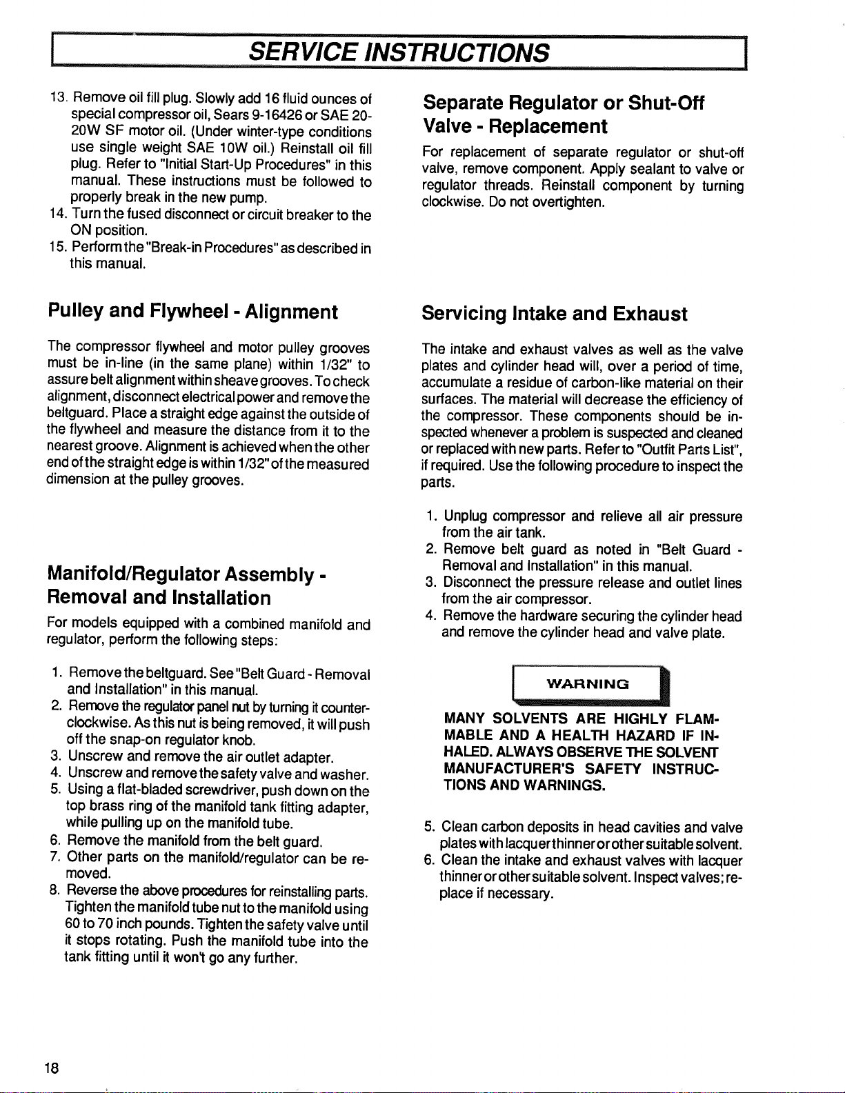
13. Remove oil fill plug. Slowly add 16 fluid ounces of
special compressor oil, Sears 9-16426 or SAE 20-
20W SF motor oil. (Under winter-type conditions
use single weight SAE 10W oil.) Reinstall oil fill
plug. Refer to "Initial Start-Up Procedures" in this
manual. These instructions must be followed to
properly break in the new pump.
14. Turn the fused disconnect or circuit breaker to the
ON position.
15. Perform the "Break-in Procedures" as described in
this manual.
Separate Regulator or Shut-Off
Valve - Replacement
For replacement of separate regulator or shut-off
valve, remove component. Apply sealant to valve or
regulator threads. Reinstall component by turning
clockwise. Do not overtighten.
Pulley and Flywheel - Alignment
The compressor flywheel and motor pulley grooves
must be in-line (in the same plane) within 1/32" to
assure belt alignment within sheave grooves. To check
alignment, disconnect electrical power and remove the
beltguard. Place a straight edge against the outside of
the flywheel and measure the distance from it to the
nearest groove. Alignment is achieved when the other
end of the straight edge iswithin 1/32" of the measured
dimension at the pulley grooves.
Manifold/Regulator Assembly -
Removal and Installation
For models equipped with a combined manifold and
regulator, perform the following steps:
1. Removethe beltguard. See"Belt Guard - Removal
and Installation" inthis manual.
2. Remove the regulator panel rut byturning itcounter-
clockwise. As this nut is being removed, itwill push
off the snap-on regulator knob.
3. Unscrew and remove the air outlet adapter.
4. Unscrew and remove the safety valve and washer.
5. Using a flat-bladed screwdriver, push down on the
top brass ring of the manifold tank fitting adapter,
while pulling up on the manifold tube.
6. Remove the manifold from the belt guard.
7. Other parts on the manifold/regulator can be re-
moved.
8. Reverse the above procedures for reinstalling parts.
Tighten the manifold tube nut to the manifold using
60 to 70 inch pounds. Tighten the safety valve until
it stops rotating. Push the manifold tube into the
tank fitting until it won_ go any further.
Servicing Intake and Exhaust
The intake and exhaust valves as well as the valve
plates and cylinder head will, over a period of time,
accumulate a residue of carbon-like material on their
surfaces. The material will decrease the efficiency of
the compressor. These components should be in-
spected whenever a problem is suspected and cleaned
or replaced with new parts. Refer to "Outfit Parts List",
if required. Use the following procedure to inspect the
parts.
1. Unplug compressor and relieve all air pressure
from the air tank.
2. Remove belt guard as noted in "Belt Guard -
Removal and Installation" in this manual.
3. Disconnect the pressure release and outlet lines
from the air compressor.
4. Remove the hardware securing the cylinder head
and remove the cylinder head and valve plate.
MANY SOLVENTS ARE HIGHLY FLAM-
MABLE AND A HEALTH HAZARD IF IN-
HALED. ALWAYS OBSERVE THE SOLVENT
MANUFACTURER'S SAFETY INSTRUC-
TIONS AND WARNINGS.
5. Clean carbon deposits in head cavities and valve
plates with lacquer thinner or other suitable solvent.
6. Clean the intake and exhaust valves with lacquer
thinner or other suitable solvent. Inspect valves; re-
place if necessary.
18
l .....SERVICE INSTRUCTIONS ................
NOTE
Do not use gasket cement on any gasket
surface as this may clog compressor valve
cavities and flow areas.
7. Reinstall valve plate and gaskets.
8. Install the cylinder head. Snug mounting screws
and studs tight, then torque to 25 to 30 foot pounds
starting at the center and working toward the out-
side.
9. Reconnect the pressure release and outlet lines to
the compressor pump.
i STORAGE OF COMPRESSOR OUTFIT I
1. Review the "Maintenance" section on the preced-
ing pages and perform scheduled maintenance as
necessary. Drain the water from the air tank.
2. Set the ON/AUTO-OFF switch to the "OFF" posi-
tion, and unplug the unit.
3. Remove any air tool or accessory.
4. Protect the electrical cord and air hose from dam-
age (such as being stepped on or runover). Wind
them loosely around the outfit handle.
5. Store the compressor in a clean and dry location.
19
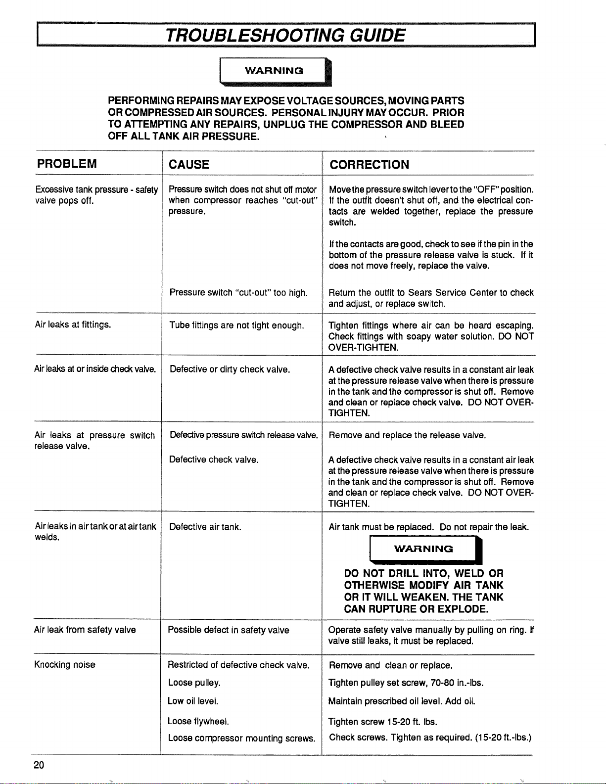
WARNING
PERFORMING REPAIRS MAY EXPOSE VOLTAGE SOURCES, MOVING PARTS
OR COMPRESSEDAIR SOURCES. PERSONAL INJURY MAY OCCUR. PRIOR
TO AI-rEMPTING ANY REPAIRS, UNPLUG THE COMPRESSOR AND BLEED
OFF ALL TANK AIR PRESSURE.
PROBLEM
Excessivetank pressure- safety
valve pops off.
Air leaks at fittings.
Airleaksator insidecheckvalve.
pressure switch
Air leaks at
release valve.
CAUSE CORRECTION
Air leaksin airtank oratairtank
welds.
Air leakfrom safety valve
Knocking noise
Pressureswitchdoesnotshut offmotor
when compressorreaches "cut-out"
pressure.
Pressure switch "cut-out" too high.
Tube fittings are not tight enough.
Defectiveor dirty check valve.
Defectivepressureswitchreleasevalve.
Defectivecheck valve.
Defective air tank.
Possible defect in safety valve
Restricted of defective check valve.
20
Movethepressure switchlevertothe"OFF" position.
If the outfit doesn't shut off, and the electrical con-
tacts are welded together, replace the pressure
switch.
Ifthe contactsaregood,checktosee ifthepininthe
bottomofthe pressurerelease valve isstuck. If it
doesnot movefreely, replacethevalve.
Retum the outfitto Sears Service Center to check
and adjust, orreplaceswitch.
Tighten fittings where air can be heard escaping.
Check fittings with soapy water solution. DO NOT
OVER-TIGHTEN.
A defective check valve results in a constant air leak
at the pressure release valve when there is pressure
in the tank and the compressor is shut off. Remove
and clean or replace check valve. DO NOT OVER-
TIGHTEN.
Remove and replace the release valve.
A defective check valve results in a constant air leak
at the pressure release valve when there is pressure
in the tank and the compressor is shut off. Remove
and clean or replace check valve. DO NOT OVER-
TIGHTEN.
Airtankmust be replaced. Do not repair the leak.
WARNING I
DO NOT DRILL INTO, WELD OR
OTHERWISE MODIFY AIR TANK
OR IT WILL WEAKEN. THE TANK
CAN RUPTURE OR EXPLODE.
Operate safetyvalve manuallyby pullingon ring. If
valvestillleaks,it mustbe replaced.
Remove and clean or replace.
Loose pulley.
Low oil level.
Loose flywheel.
Loosecompressor mounting screws.
13ghtenpulley set screw, 70-80 in.-Ibs.
Maintain prescribedoillevel. Add oil.
Tighten screw 15-20 ft. Ibs.
Check screws.Tighten as required. (15-20 ft.-Ibs.)
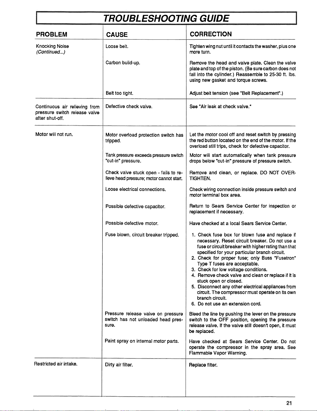
PROBLEM
KnockingNoise
(Continued...)
Continuous air relievingfrom
pressure switch releasevalve
after shut-off.
CAUSE
Loosebelt.
Carbon build-up.
Belt too tight.
Defectivecheckvalve.
Motorwillnot run.
Restricted air intake.
Motor overload protection switchhas
tripped.
Tankpressureexceedspressureswitch
"cut-in"pressure.
Check valve stuck open - fails to re-
lieve head pressure; motor cannot start.
Loose electrical connections.
Possibledefectivecapacitor.
Possible defective motor.
Fuse blown, circuit breaker tripped.
Pressure release valve on pressure
switch has not unloaded head pres-
sure.
Paintspray on internalmotor parts.
Dirty airfilter.
CORRECTION
Tightenwingnutuntilitcontactsthewasher,plusone
moreturn.
Removethe head and valve plate. Cleanthe valve
plateandtopofthe piston.(Besurecarbondoes not
fall into the cylinder.) Reassemble to 25-30 ft. Ibs.
using newgasket and torque screws.
Adjust belt tension (see "Belt Replacement".)
See "Air leak at check valve."
Let the motor cool off and reset switch by pressing
the red button located on the end of the motor. If the
overload still trips, check for defective capacitor.
Motor wilt start automatically when tank pressure
drops below "cut-in" pressure ofpressureswitch.
Remove and clean, or replace. DO NOT OVER-
TIGHTEN.
Checkwiringconnectioninsidepressureswitchand
motorterminalbox area.
Return to Sears Service Center for inspectionor
replacementifnecessary.
Havecheckedat a local Searsservice Center.
1. Check fuse box for blown fuse and replaceif
necessary. Reset circuitbreaker. Do not usea
fuse orcircuitbreakerwithhigherratingthanthat
specifiedfor your particularbranchcircuit.
2. Check for proper fuse; only Buss "Fusetron"
Type T fuses are acceptable.
3. Checkfor low voltageconditions.
4. Removecheckvalveand cleanorreplaceifitis
stuckopenor closed.
5. Disconnectanyotherelectricalappliancesfrom
circuit.The compressormustoperateonitsown
branchcircuit.
6. Do notusean extension cord.
Bleedthe linebypushingthe leveronthepressure
switchto the OFF position,openingthe pressure
releasevalve. Ifthe valve stilldoesn'topen,itmust
be replaced.
Have checked at Sears Service Center. Do not
operate the compressor in the spray area. See
FlammableVaporWarning.
Replacefilter.
21
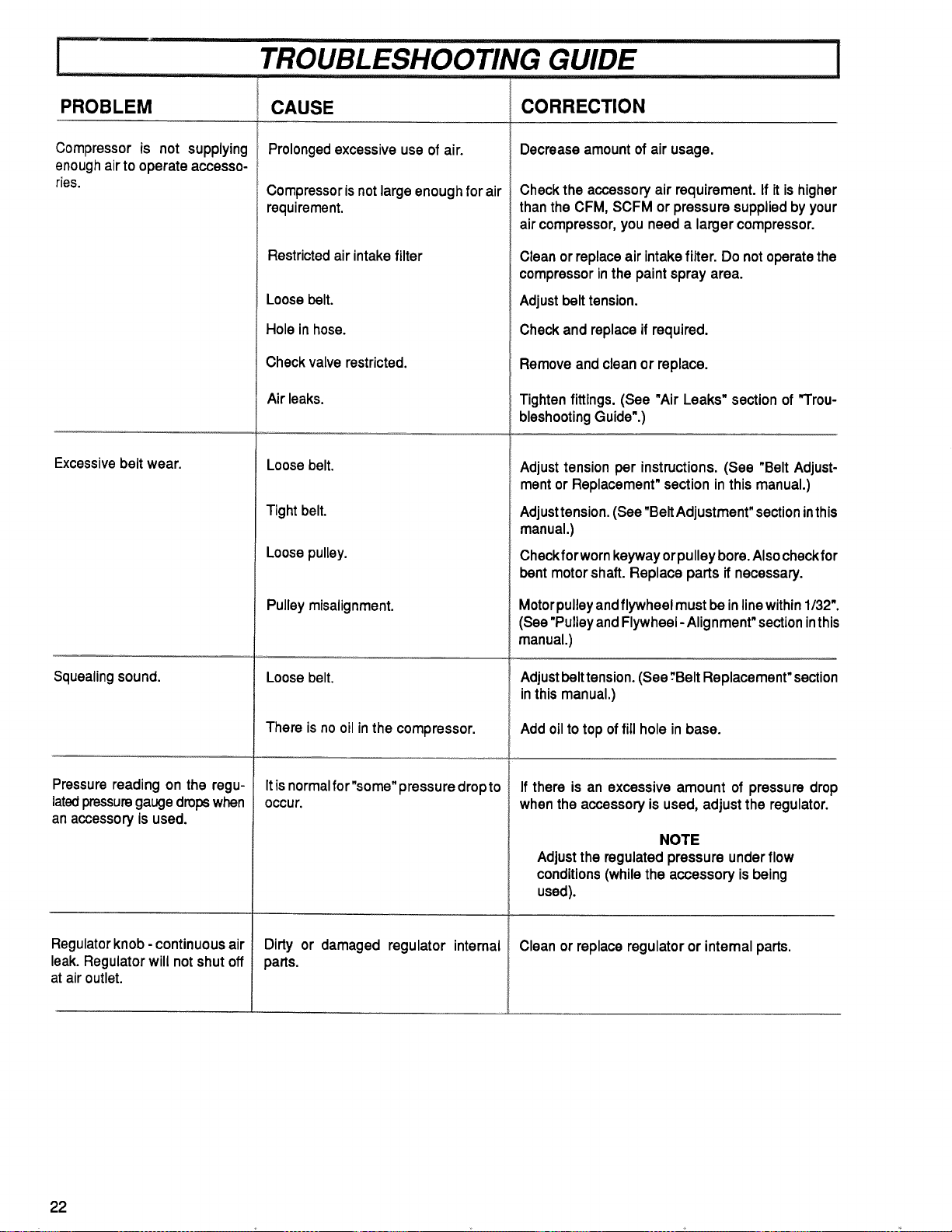
TROUBLESHOOTING GUIDE !
PROBLEM
Compressor is not supplying
enough air to operate accesso-
ries.
CAUSE
Prolongedexcessiveuseofair.
Compressorisnotlargeenoughfor air
requirement.
Excessive belt wear.
Squealing sound.
Pressure readingon the regu-
latedpressuregaugedropswhen
anaccessoryisused.
Regulatorknob - continuous air
leak.Regulator willnot shut off
at air outlet.
Restricted air intake filter
Loose belt.
Hole in hose.
Check valve restricted.
Airleaks.
Loose belt.
Tight belt.
Loose pulley.
Pulleymisalignment.
Loosebelt.
There is no oil in the compressor.
Itisnormalfor"some"pressure dropto
OCCUr.
Dirty or damaged regulator intemal
parts.
CORRECTION
Decreaseamountofair usage.
Checkthe accessoryair requirement.If itishigher
thanthe CFM, SCFM or pressuresuppliedbyyour
aircompressor,youneed a largercompressor.
Cleanorreplaceair intakefilter. Do notoperatethe
compressorinthepaintsprayarea.
Adjustbelttension.
Checkand replaceifrequired.
Removeandcleanor replace.
Tightenfittings. (See "Air Leaks"sectionof "Trou-
bleshootingGuide".)
Adjusttensionper instructions.(See "Belt Adjust-
mentorReplacement"sectioninthis manual.)
Adjusttension.(See"BeltAdjustment"sectioninthis
manual.)
Checkforwornkeywayorpulleybore.Alsocheckfor
bent motor shaft. Replace parts ifnecessary.
Motorpulley andflywheel must be inline within 1/32".
(See "PulleyandFlywheel- Alignment" section inthis
manual.)
Adjust belttension. (See "Belt Replacement"section
inthis manual.)
Add oil to top offill hole in base.
If there is an excessive amount of pressure drop
when the accessory is used, adjust the regulator.
NOTE
Adjust the regulated pressure under flow
conditions (whilethe accessory is being
used).
Clean or replace regulator or intemal parts.
22
i ................. _ SERVICE NOTES 1
23

SEARS
CRAFTSMAN
SERVICE
MODEL NO.
HOW TO ORDER
REPAIR PARTS
GENERAL MANUAL FOR
OIL LUBRICATED
SINGLE STAGE
AIR COMPRESSORS
Now that you have purchased your Sears Air Compressor, should a
need ever exist for repair parts or service, simplycontact any Sears
Service Center and most Sears, Roebuck and Co. stores. Be sure to
provide all pertinent facts when you call or visit.
The modelnumber of your Sears Air Compressor can be found on the
label which is located on the back of the shroud.
WHEN ORDERING REPAIR PARTS, ALWAYS GIVE THE FOL-
LOWING INFORMATION:
PART NUMBER • PART DESCRIPTION
MODEL NUMBER NAME OF ITEM
All parts listed may be ordered from any Sears Service Center and
most Sears stores.
If the parts you need are not stocked locally, your order will be
electronically transmitted to a Sears Repair Parts Distribution Center
for handling.
Sears, Roebuck and Co., Chicago, IL 60684 U.S.A.