Amana Technical Information--Refrigerator
TSI25V P1308102W
Due to a possibility of personal injuryor propertydamage, always contact an authorized technician for servicing
or repair of this refrigerator.
• Refer to Service Manual RS1100000 for installation, operating, disassembly, ice maker, testing, and
troubleshooting information.
• Refer to Parts Manual RP1100056 for parts information.
I CAUTION
All safety information must be followed as provided in Service Manual RS1100000.
t
I WARNING
To avoid risk of electrical shock, personal injury,or death, disconnect power to refrigerator before servicing,
unless testing requires power. Wires removed during disassembly must be replaced on proper terminals to
insure correct earthing and polarization.
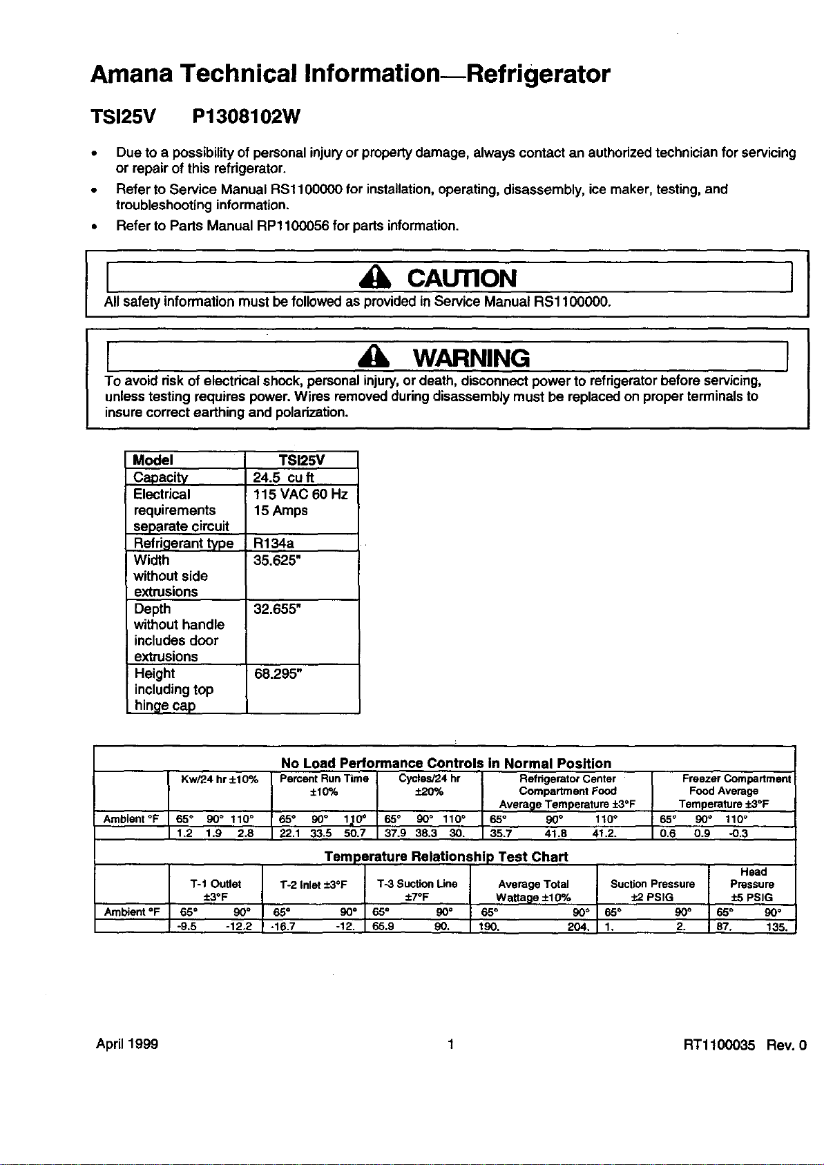
Model TSI25V
Capacity 24.5 cuft
Electrical 115 VAC 60 Hz
requirements 15 Amps
separate circuit
Refrigerant type R134a
Width 35.625"
without side
extrusions
Depth 32.655"
without handle
includes door
extrusions
Height 68.295"
including top
hinge cap
Ambient °F
Ambient °F
Kw/24 hr +10%
65° 90° 110°
1,2 1.9 2.8
No Load Performance Controls In Normal Position
Percent Run Time Cycles/24 hr Refdgerator Center
+10% _ Compartment Food
Avera_le Temperature +3°F
65 ° 90" lm10° 65 _ 90 ° 110 ° 65 ° 90° 110 °
22.1 33,5 50.7 37.9 38.3 30. 35.7 41.8 41,2.
Freezer Compartment
Food Average
Temperature :P.3°F
65° 90° 110 °
I 0.6 0.9 -0.3
Temperature Relationshi ) Test Chart
T-I Outlet T-2 inlet +3°F
±3OF
65° 90 ° 65° 90°
-9.5 -12.2 -16.7 -12.
T-3 Suction Line
+7OF
65° gO°
65.9 90.
Head
Average Total Suction Pressure Pressure
Wattage ±10% :L2 PSIG :t:5PSIG
65° 90° 65° 90° 65° 90°
190. 204. 1. 2. 87. 135.
April1999 1 RTl100035 Rev. 0

Component Specifications
[ WARNING I
To avoid risk of electrical shook, personal injury, or death, disconnect power to oven before servicing, unless
testing requires it.
Component Test Procedure
Bulb Colt 115/125 VAC
Hatt 40 wars
Capacitor, compressor run Volt 220 VAC
_,apacitance 15 Mfd + 10%
-5%
Compressor
Illustration
_0282803
38931604
12049711
_0161072
10428508
B215050 ___
2._1, damper
_r_, freezer tembemture
Type Fan cooled, R134a refrigerant
BTUH 970 BTUH
Volt 115 VAC, 60 Hz
Watt 176 watts
Current
Lock rotor 21.3 amps
Full load 1.6 amps
Resistance
Run windings 2.60 ohms
Start windings 4.35 ohms
Settings Closingtemperatures
if1 43"F
#4 30°F
#7 16°F
Settings Temperatures
#1 - in 15.1°F
#1 - out 6.0°F
#4 - in 6.5°F
#4 - Out -4.0°F
#7 - in 1.9°F
#7 -out -9.5°F
Driermostbechangedevery time the systemisoponedfortestingor compressor
rep/acemant.
Desiccant
(20) 5 x 12 4AXH - 7 M>S> -Grams
10991110 Heater, evaporator Volt 115 VAC
_ Wattage 505 ±5% watts
Resistance 29 +5% ohms
10884501 Motor, condenser Volt 115 VAC, 60 Hz
Rotation (facing end opposite Clockwise
shaft)
RPM 1300 RPM
Watt 10.0 watts
Current 0.15 amps
Resistance 220 ±10% ohms
RTl100035 Rev. 0 2 April 1999
Component Specifications
I WARNING I
To avoid risk of electrical shook, personal injury,or death, disconnect power to oven before servicing, unless
testing requires it.
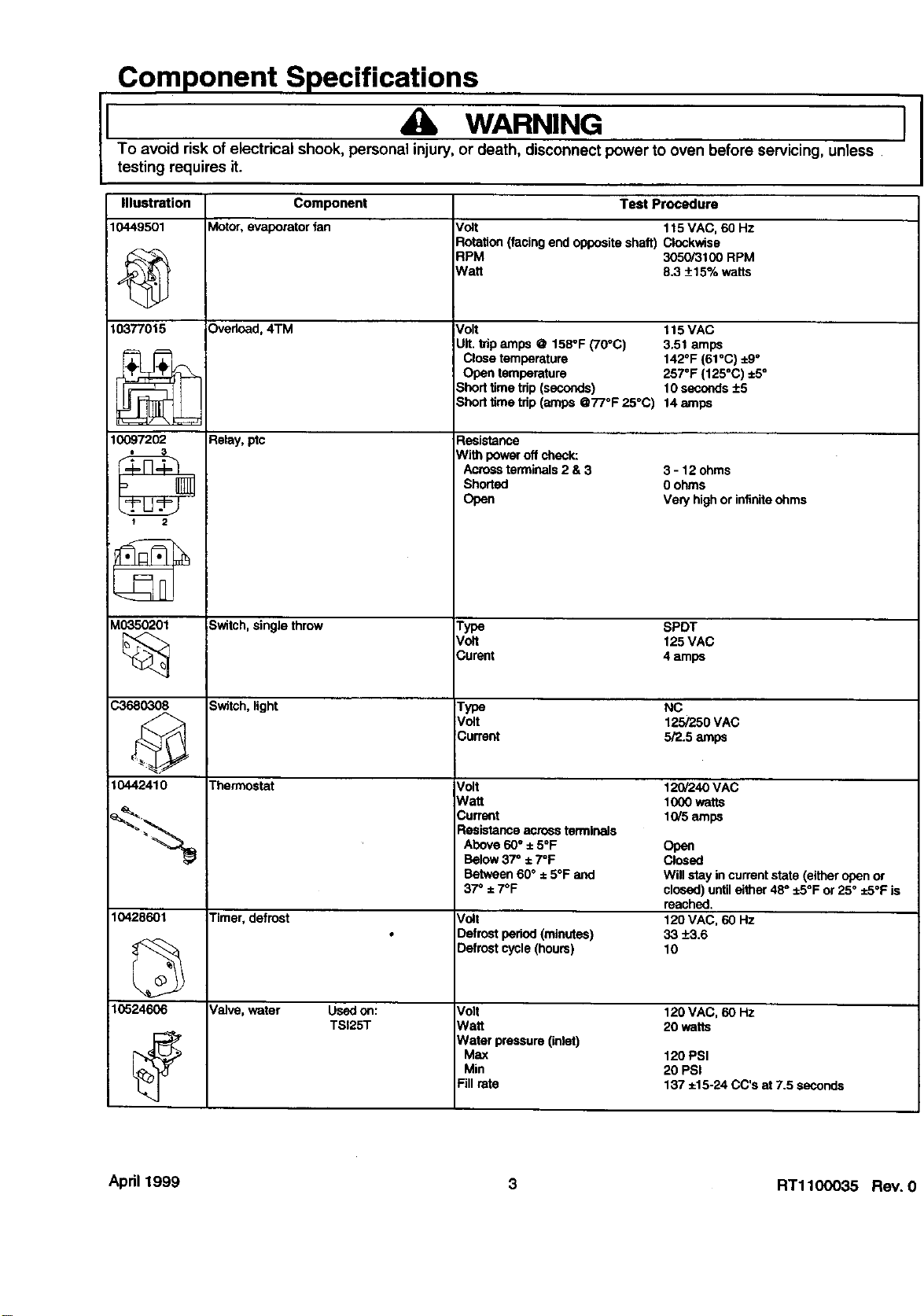
Component Test Procedure
Motor, evaporator fan Volt 115 VAC, 60 Hz
Rotation (facing end opposite shatt) Clockwise
RPM 3050/3100 RPM
I/Vatt 8.3 _+15% watts
Overload, 4TM Volt 115 VAC
UIt. trip amps @ 158°F (70°C) 3.51 amps
Close temperature 142°F (61°C) _9°
Open temperature 257=F (125°C) ±.5°
Short time trip (seconds) 10 seconds -+5
Shorttimetdp(amps @770F25°C) 14amps
Relay, ptc
Illustration
10449501
10377015
10097202
• 3
2
_0350201
%
Resistance
With poweroffcheck:
Acrossterminals2& 3
Shorted
Open
3 - 12ohms
0 ohms
Very highor infiniteohms
Switch, single throw Type SPDT
Volt 125 VAC
Curent 4 amps
.33680308 Switch, light Type NC
Volt 125/250 VAC
Current 5/2.5 amps
10442410 Thermostat 120/'240 VAC
1000 watts
10/5 amps
Volt
Watt
Current
Resistanceacrossterminals
Above60° ± 5°F
Below37=±7°F
Between60° ±5°F and
37_± 7°F
10428601 Timer, defrost Volt
Defrost peried (minutes)
Defrost cycle (hours)
10524606 Valve, water Used on: Volt 120 VAC, 60 HZ
TSI25T Watt 20 watts
Water pressure (inlet)
Max 120 PSI
Min 20 PSI
Fill rate 137 ±15-24 CC's at 7.5 seconds
Open
Closed
Will stay in current state (either open or
closed) until either 48 ° ±5°F or 25° ±5°F is
reached,
120 VAC, 60 Hz
33 +-3.6
10
April 1999 3 RTl100035 Rev. 0
Wiring Diagrams and Schematics
4_ WARNING II
To avoid risk of electrical shook, personal injury, or death, disconnect power to oven before servicing, unless
testing requires it.
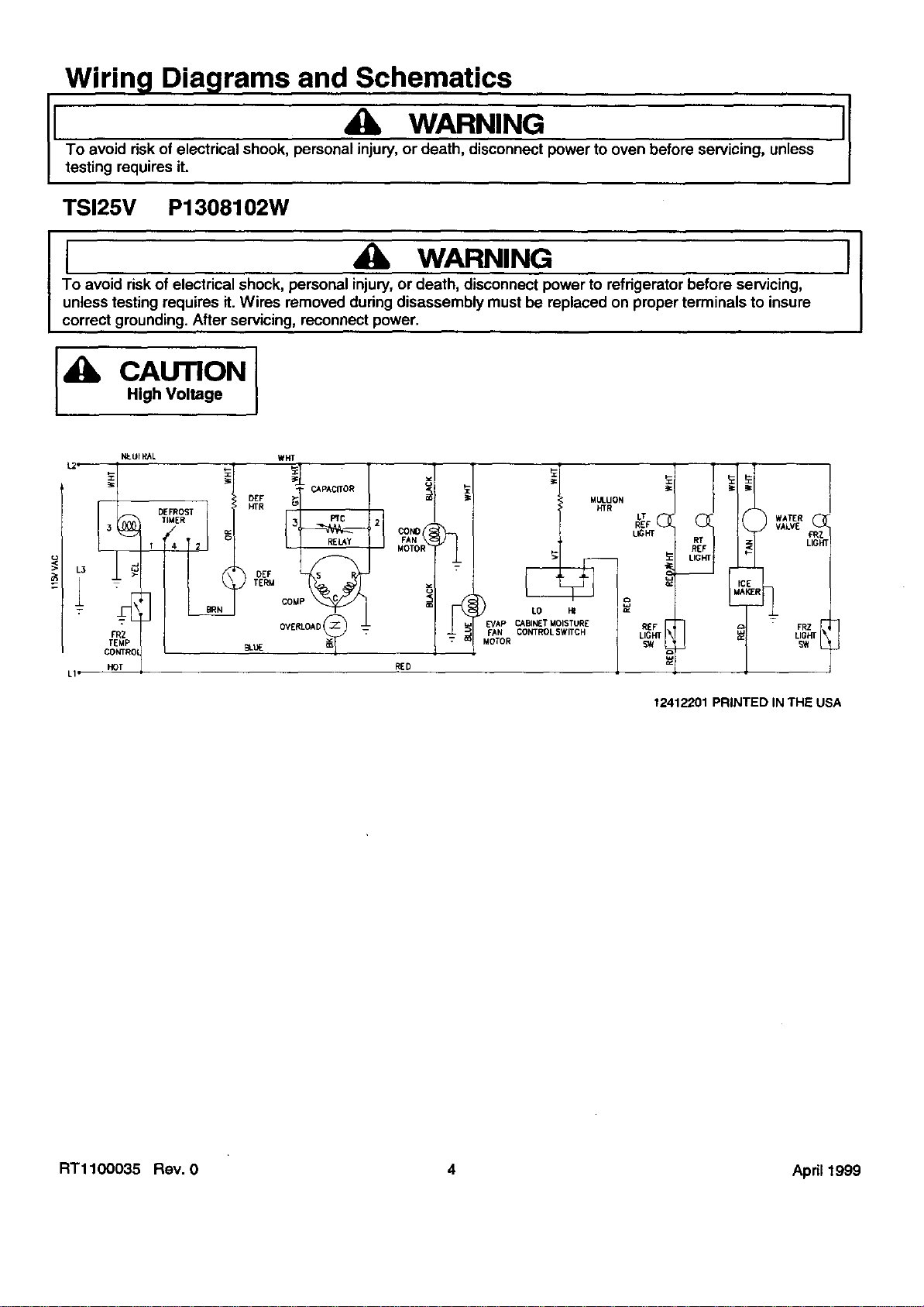
TSI25V P1308102W
I 4_ WARNING I
To avoid risk of electrical shock, personal injury, or death, disconnect power to refrigerator before servicing,
unless testing requires it. Wires removed during disassembly must be replaced on proper terminals to insure
correct grounding. After servicing, reconnect power.
_lk CAUTION
High Voltage
_UI_L
I L2_ DEFROST
7
LI" HOT
D_F
HTR
DEF
TERM
LO H= _-
CABINETMOISTURE
FAN CONTROLSWITCH
MOTOR
HTR LT
REF_ (
uc_
WATER
VALVE
FRZ
12412201 PRINTED IN THE USA
RTl100035 Rev. 0 4 April 1999
Wiring Diagrams and Schematics
II 4J_ WARNING
To avoid risk of electrical shook, personal injury,or death, disconnect power to oven before servicing, unless
testing requires it.
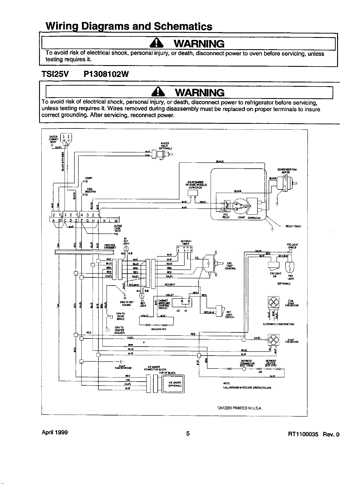
TSI25V P1308102W
I A WARNING I
To avoid risk of electrical shook, personal injury, or death, disconnect power to refrigerator before servicing,
unless testing requires it. Wires removed during disassembly must be replaced on proper terminals to insure
correct grounding. After servicing, reconnect power.
OUTER
!
REO
I
12412201PRINTEDINU.S._.
April 1999 5 RTl100035 Rev. 0