Loading ...
Loading ...
Loading ...
9
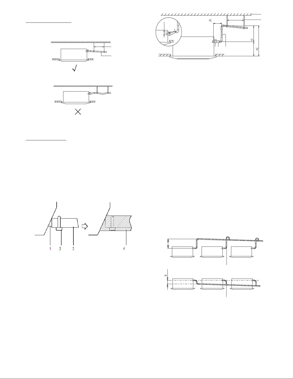
DRAIN PIPING WORK
Drain Piping Installation
Install the drain piping (see Fig. 10) and take steps to eliminate
condensation. Improperly rigged piping could lead to leaks and
eventually wet furniture and belongings.
1-1.5m
1
2
3~5ft
Fig. 10 - Drain Piping Installation
Fig. 11 - Hanging Bar
(1.) Hanging bar
(2.)
≥1/100 gradient
Install the Drain Pipes
IMPORTANT: Observe all local sanitary codes when installing
condensate drains.
S Keep piping as short as possible and slope it downwards
at a gradient of at least 1/100 so that air does not remain
trapped inside the pipe.
S Keep the pipe size equal to or greater than that of the
connecting pipe (PVC pipe, nominal diameter 0.8 in.
(20mm), outside diameter .98 in. (25mm)).
S Push the drain hose as far as possible over the drain
socket, and tighten the metal clamp securely.
Fig. 12 - Push the Drain Hose
1. Drain socket (attached to the unit)
2. Metal clamp
3. Drain hose
4. Insulation (field supply)
a. Insulate the drain hose inside the building.
b. If the drain hose cannot be sufficiently set on a slope, fit
the hose with the drain raising piping (field supplied).
c. Ensure the heat insulation work is executed on the
following two spots to prevent any possible water
leakage due to dew condensation:
(1.) Indoor drain pipe
(2.) Drain socket.
Unit: mm
1
2
57~0
5
1~1.5m
300/11.8in
6
5
4
3
n
i
7.8/022
ni5
.
9
2/
0
57
ni3~0
n
i9.02/035
3~5ft
Fig. 13 - Drain Setup Pipe
1. Ceiling slab
2. Hanger bracket
3. Adjustable range
4. Drain raising pipe
5. Drain hose
6. Metal clamp
− Connect the drain hose to the drain raising pipes, and
insulate them.
− Connect the drain hose to the drain outlet on the indoor unit,
and tighten it with the clamp.
NOTE: Drain setup pipe:
S The install height of the drain raising pipe should be less
than 21 in. (530 mm).
S The drain raising pipe should form a right angle with the
unit. The distance to the unit should not exceed 11.81 in.
(300 mm).
S To prevent air bubbles, install the drain hose level at an
angle slightly tilted upward (</3 in / 75 mm).
S The drain hose incline should be 3 in (75 mm) or less so
the drain socket does not have to withstand additional force.
S To ensure a downward slope of 1:100, install the hanging
bars every 3.3 ft. (1m) to /4.9 ft./(1.5 m).
S When unifying the multiple drain pipes, install the pipes as
shown in Fig. 14. Select the converging drain pipes whose
gauge is suitable for the operating capacity of the unit.
1 T-joint converging drain pipes
035-
0
0
01
1
1
Unit: mm
Fig. 14 - T−Joint Converging Drain Pipes
S Connect the drain hose to the drain raising pipes, and
insulate them.
S Connect the drain hose to the drain outlet on the indoor
unit, and tighten it with the clamp.
Loading ...
Loading ...
Loading ...