Loading ...
Loading ...
Loading ...
14
INSTALL ALL POWER, INTERCONNECTING
WIRING, AND PIPING TO INDOOR UNIT
1. Run interconnecting piping and wiring from the outdoor
unit to the indoor unit.
2. Connect wiring from the outdoor unit per the connection
diagram (see Fig. 26).
3. Replace the field wiring cover and close the indoor unit
front cover.
4. Connect the refrigerant piping and a drain line outside of
the indoor unit. Complete the pipe insulation at the flare
connection then fasten the piping and wiring to the wall as
required. Completely seal the hole in the wall.
5. Piping:
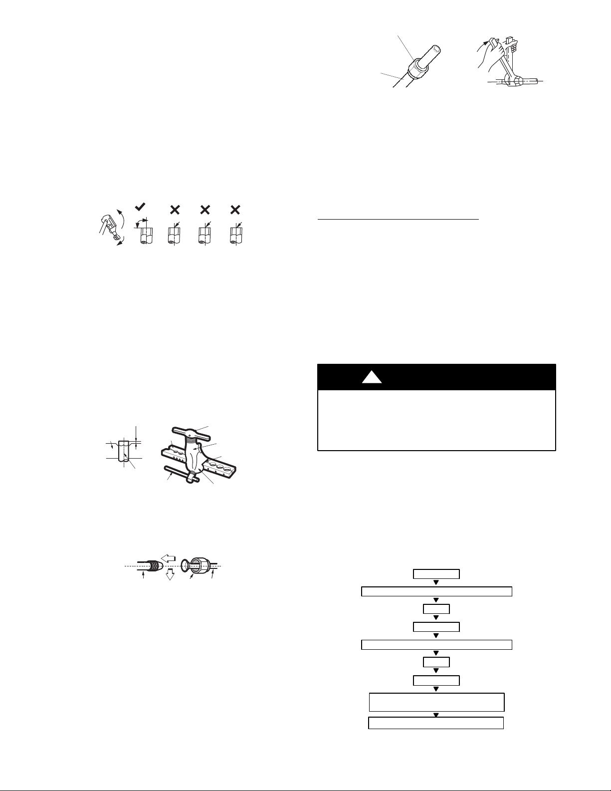
a. Cut the pipe, with a pipe cutter, at 90 degrees (see Fig. 28).
b. Remove the service connection, if provided with the unit.
Oblique
DŽ
90
Roughness
Burr
A150767
Fig. 28 - Pipe Cutting
c. Remove all the burrs from the cut cross section of the pipe
avoiding any burrs inside the tubes.
d. Remove the flare nuts attached to the indoor and outdoor
units.
e. Install the correct size flare nut onto the tubing and make
the flare connection. See Table 6 for the flare nut spaces.
Table 6—Flare Nut Spacing
OUTER DIAM. (mm)
A (mm)
Max. Min.
Ø 1/4" (6.35) 0.05 (1.3) 0.03 (0.7)
Ø 3/8" (9.52) 0.06 (1.6) 0.04 (1.0)
Ø 1/2" (12.7) 0.07 (1.8) 0.04 (1.0)
Ø 5/8" (15.88) 0.09 (2.2) 0.08 (2.0)
Bar
Copper pipe
Clamp handle
Red arrow mark
Cone
Yoke
Handle
Bar
"A"
A150768
Fig. 29 - Flare Nut Spacing
f. Apply a small amount of refrigerant oil to the flare
connection on the tubing.
g. Align the center of the pipes and/or service valve.
Indoor unit tubing Flare nut Piping
A150769
Fig. 30 - Align Pipe Center
h. Connect both the liquid and gas piping to the indoor unit.
i. Tighten the flare nut using a torque wrench as specified in
Table 7.
Table 7—Tightening Torque
PIPE DIAMETER
INCH (mm)
TIGHTENING TORQUE
Ft-lb N-m
Ø1/4” (6.35) 10 to 13 13.6 to 17.6
Ø3/8” (9.52) 24 to 31 32.5 to 42.0
Ø1/2” (12.7) 37 to 46 50.1 to 62.3
Ø5/8” (15.88) 50 to 60 67.7 to 81.3
Flare nut
Copper tube
A150770
Fig. 31 - Tighten the Flare Nut
6. Connect the drain line. The drain line must not have a trap
anywhere in its length. The drain line must pitch downwards.
The drain line must be insulated up to the outside wall.
NOTE: For applications where gravity cannot be used for
drainage, a condensate pump accessory is available. Consult the
condensate pump Installation Instructions for more information.
WIRELESS REMOTE CONTROL INSTALLATION
Mounting Bracket (if installed on the wall)
1. Use the two screws supplied with the control to attach the
mounting bracket to the wall in a location selected by the
customer and within operating range.
2. Install the remote control batteries.
3. Place the remote control into the remote control mounting
bracket.
4. For remote control operation, refer to the unit owner’s
manual.
WIRED REMOTE CONTROLLER
For setup instructions, refer to the wired controller installation
manual. Refer to Fig. 24 for the 4 and 5 Pin connections for the
different wired remote controllers.
UNIT DAMAGE HAZARD
Failure to follow this caution may result in equipment
damage or improper operation.
Never use the system compressor as a vacuum pump.
CAUTION
!
Refrigerant tubes and the indoor coil should be evacuated using the
recommended deep vacuum method (500 microns). The alternate
triple evacuation method may be used if the procedure outlined
below is followed. Always break a vacuum with dry nitrogen.
FINAL TUBING CHECK
IMPORTANT: Ensure certain factory tubing on the indoor unit
has not shifted during shipment. Ensure tubes are not rubbing
against each other or any sheet metal. Pay close attention to the
feeder tubes, making sure the wire ties on the feeder tubes are
secure and tight.
CHECK FOR TIGHT, DRY SYSTEM
(IF IT HOLDS DEEP VACUUM)
EVACUATE
BREAK VACUUM WITH DRY NITROGEN
WAIT
EVACUATE
RELEASE CHARGE INTO SYSTEM
BREAK VACUUM WITH DRY NITROGEN
EVACUATE
WAIT
A95425
Fig. 32 - Triple Evacuation Method
Loading ...
Loading ...