Loading ...
Loading ...
Loading ...
8
INDOOR UNIT MAIN BODY INSTALLATION
1. Prepare the ceiling opening needed for installation where
applicable (for existing ceilings).
a. Create the ceiling opening required for installation. From the
side of the opening to the casing outlet, implement the
refrigerant and drain piping and wiring for the remote
controller (unnecessary for the wireless type). Refer to each
piping or wiring section.
b. After creating an opening in the ceiling, it may be
necessary to reinforce the ceiling beams to keep the
ceiling level and to prevent it from vibrating. Consult
the builder for details.
2. Install the installation hooks. Use either a M8 or M10 bolt.
a. Use expansible hooks, sunken anchors or other field
supplied parts to reinforce the ceiling to bear the unit’s
weight.
b. Adjust the clearance from the ceiling before proceeding
further. For an installation example, see Fig. 7.
1
2
3
4
Fig. 7 - Installation Clearances
(1.) Ceiling slab
(2.) Expansible hook (optional)
(3.) Installation hook (optional)
(4.) False ceiling
NOTE: For a non−standard installation, contact your dealer for
details.
When installing optional accessories, review the optional
accessories list in the installation manual. Depending on field
conditions, it may be easier to install optional accessories before
the indoor unit is installed (except for the decoration panel).
However, for an existing ceiling, install the fresh air inlet
component kit (field Supplied) before installing the unit.
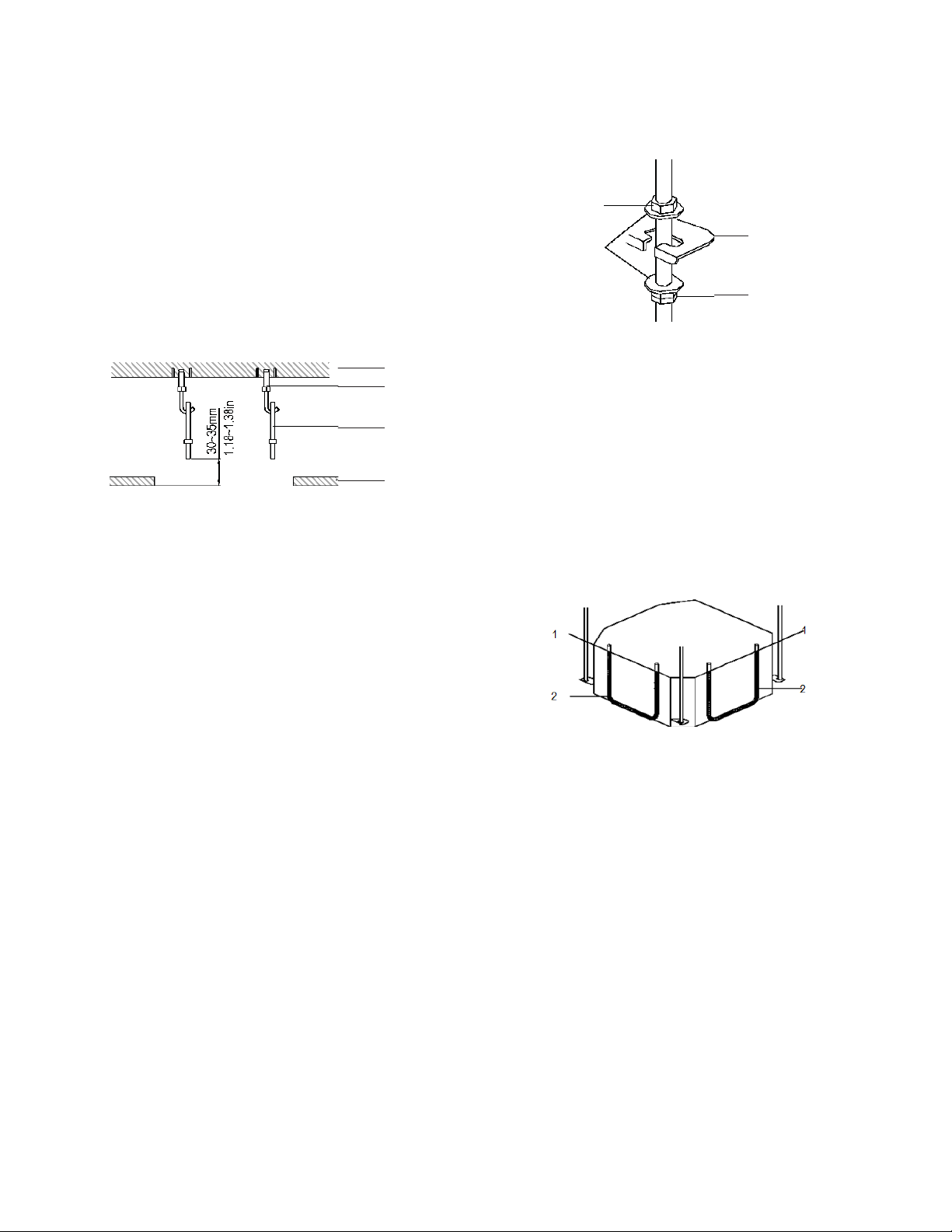
3. Install the indoor unit temporarily.
a. Attach the hanger bracket to the suspension bolt. Be sure
to fix it securely by using a nut and washer from the upper
and lower sides of the hanger bracket.
b. Secure the hanger bracket (see Fig. 8).
-
1
3
4
2
Fig. 8 - Secure the Hanger Bracket
(1.) Nut (field supply)
(2.) Washer (field supply)
(3.) Hanger bracket
(4.) Double nuts (field supply, tighten)
4. Adjust the unit to the right position for installation.
5. Check if the unit is horizontally leveled.
a. Do not install the unit tilted. The indoor unit is
equipped with a built−in drain pump and a float switch.
NOTE: If the unit is tilted against the direction of the condensate
flow (the drain piping side is raised), the float switch may
malfunction and cause water to drip.
b. Check if the unit is level at all four corners with a water
level or a water−filled vinyl tube (see Fig. 9).
Fig. 9 - Ensure unit is level
(1.) Water level
(2.) Vinyl tube
Loading ...
Loading ...
Loading ...