Loading ...
Loading ...
Loading ...
Final Adjustments
IMPORTANT:Check the adjustments as instructed and
make any final adjustments necessary before operating
the unit. Check all nuts and bolts for tightness.Failure to
follow these instructions may cause damage to unit.
Tire Pressure (Pneumatic Tires)
The tires are over-inflated for shipping purposes. Check
tire pressure and reduce pressure, if needed, to 10-15
psi. Maintain equal pressure on both wheels of the
snow throwe r.
_ WARNING: Maximum tire pressure underany circumstance is 15 psi. Equal tire pressure
should be maintained at all times. Excessive
pressure (over 15 psi) when seating beads
may cause tire/rim assembly to burst with force
sufficient to cause serious injury
Skid Shoe
The space between the shave plate and the ground can
be adjusted. Refer to Figure 6 for location of shave
plate and skid shoes.
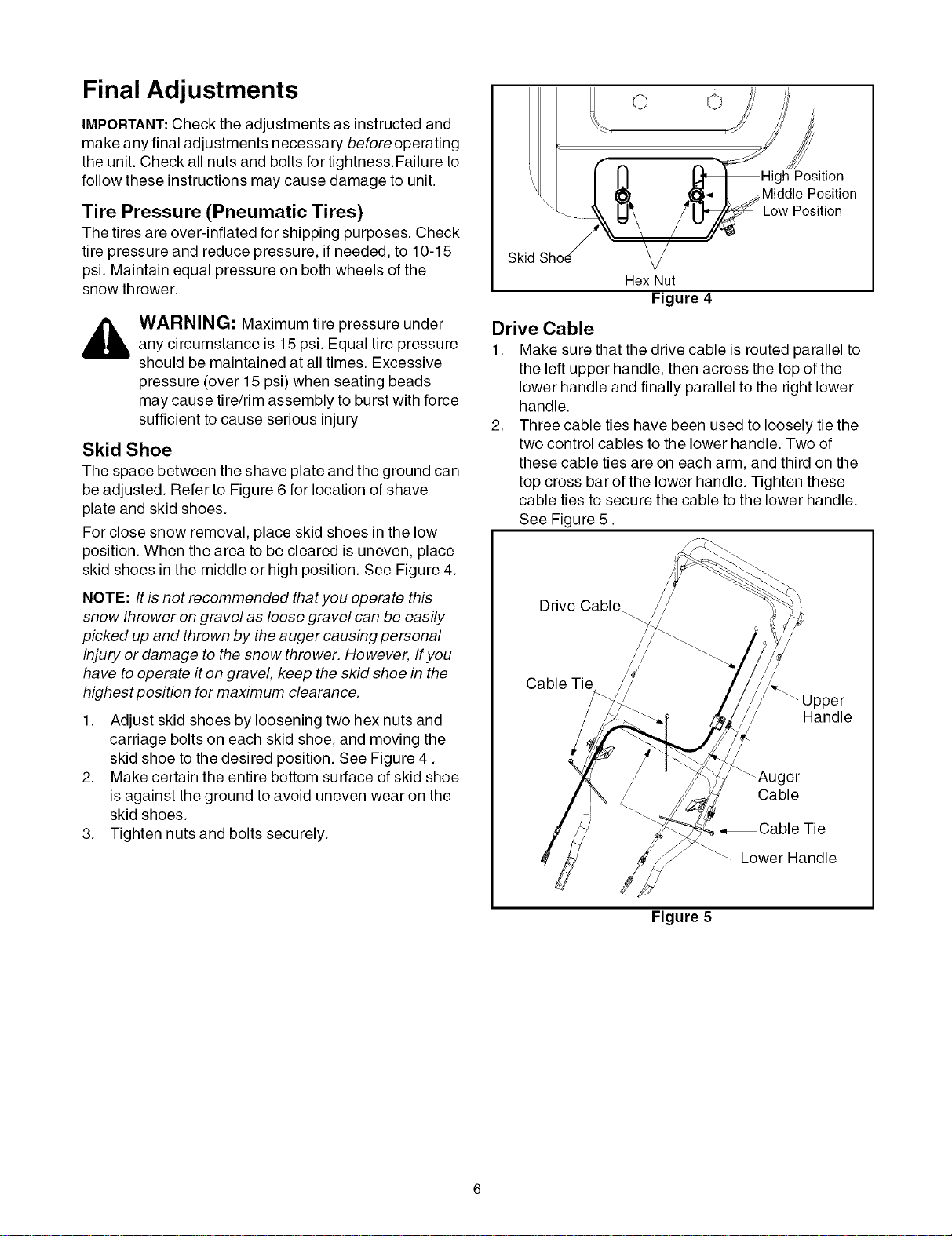
For close snow removal, place skid shoes in the low
position. When the area to be cleared is uneven, place
skid shoes in the middle or high position. See Figure 4.
NOTE: It is not recommended that you operate this
snow thrower on gravel as loose gravel can be easily
picked up and thrown by the auger causing personal
injury or damage to the snow thrower. However, if you
have to operate it on gravel, keep the skid shoe in the
highest position for maximum clearance.
1. Adjust skid shoes by loosening two hex nuts and
carriage bolts on each skid shoe, and moving the
skid shoe to the desired position. See Figure 4.
2. Make certain the entire bottom surface of skid shoe
is against the ground to avoid uneven wear on the
skid shoes.
3. Tighten nuts and bolts securely.
o o
Position
Middle Position
Low Position
Skid
Hex Nut
Figure 4
Drive Cable
1. Make sure that the drive cable is routed parallel to
the left upper handle, then across the top of the
lower handle and finally parallel to the right lower
handle.
2. Three cable ties have been used to loosely tie the
two control cables to the lower handle. Two of
these cable ties are on each arm, and third on the
top cross bar of the lower handle. Tighten these
cable ties to secure the cable to the lower handle.
See Figure 5.
Drive Cable_
Cable Tie
Handle
_Auger
Cable
•,Cable Tie
Lower Handle
Figure 5
Loading ...
Loading ...
Loading ...