Loading ...
Loading ...
Loading ...
WARNING: Always stop the engine of the
snow thrower, disconnect spark plug wire and
move it away from the spark plug before
performing any adjustments or repairs.
WARNING: Never attempt to clean the
chute assembly or make any adjustments while
the engine is running. Always wear safety
glasses during operation or while performing
any adjustments or repairs.
Shave Plate & Skid Shoes
The shave plate and skid shoes on the bottom of the
snow thrower are subject to wear. They should be
checked periodically and replaced when necessary.
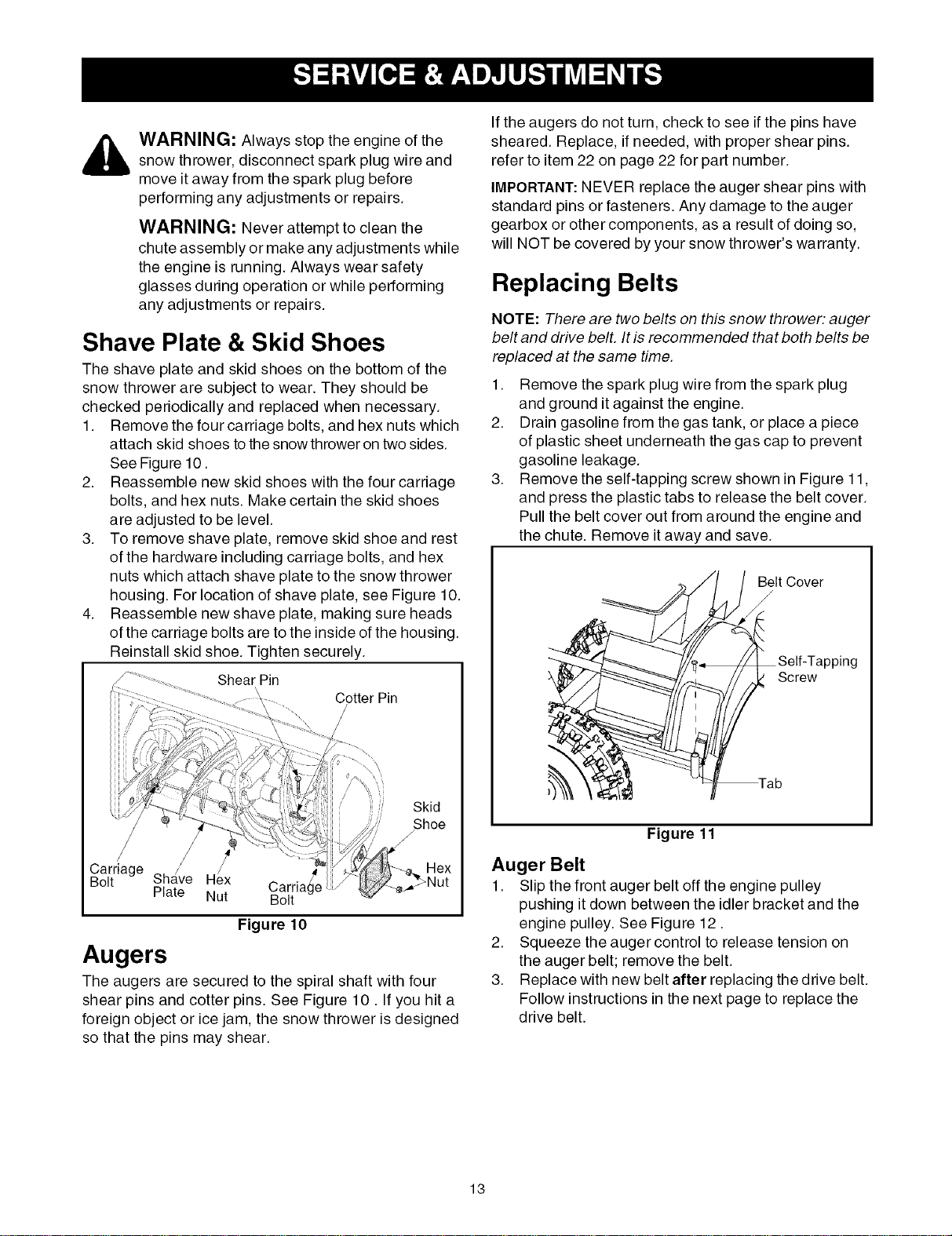
1. Remove the four carriage bolts, and hex nuts which
attach skid shoes to the snow thrower on two sides.
See Figure 10.
2. Reassemble new skid shoes with the four carriage
bolts, and hex nuts. Make certain the skid shoes
are adjusted to be level.
3. To remove shave plate, remove skid shoe and rest
of the hardware including carriage bolts, and hex
nuts which attach shave plate to the snow thrower
housing. For location of shave plate, see Figure 10.
4. Reassemble new shave plate, making sure heads
of the carriage bolts are to the inside of the housing.
Reinstall skid shoe. Tighten securely.
Shear Pin
Cotter Pin
Skid
/Shoe
Carriage
Sha/ve Hex Carria _Age
Bolt
Plate Nut Bolt
Figure 10
Augers
The augers are secured to the spiral shaft with four
shear pins and cotter pins. See Figure 10. If you hit a
foreign object or ice jam, the snow thrower is designed
so that the pins may shear.
If the augers do not turn, check to see if the pins have
sheared. Replace, if needed, with proper shear pins.
refer to item 22 on page 22 for part number.
IMPORTANT:NEVER replace the auger shear pins with
standard pins or fasteners. Any damage to the auger
gearbox or other components, as a result of doing so,
will NOT be covered by your snow thrower's warranty.
Replacing Belts
NOTE: There are two belts on this snow thrower: auger
belt and drive bell It is recommended that both belts be
replaced at the same time.
1. Remove the spark plug wire from the spark plug
and ground it against the engine.
2. Drain gasoline from the gas tank, or place a piece
of plastic sheet underneath the gas cap to prevent
gasoline leakage.
3. Remove the self-tapping screw shown in Figure 11,
and press the plastic tabs to release the belt cover.
Pull the belt cover out from around the engine and
the chute. Remove it away and save.
Belt Cover
/
Lpping
Screw
Figure 11
Auger Belt
1. Slip the front auger belt off the engine pulley
pushing it down between the idler bracket and the
engine pulley. See Figure 12.
2. Squeeze the auger control to release tension on
the auger belt; remove the belt.
3. Replace with new belt after replacing the drive belt.
Follow instructions in the next page to replace the
drive belt.
13
Loading ...
Loading ...
Loading ...