Loading ...
Loading ...
Loading ...
I
I
I
I
THROAT PLATE SLOT (Fig. 7)
The throat plate was cut (slotted) at the
factory for a 0° bevel/miter cut.
The first cut you will make with the saw will
be to increase this slot in the throat plate by
setting the bevel scale to 45 °, locking the bevel
lock knob into position and cutting into the
throat plate, increasing the width of the slot.
Fig. 7
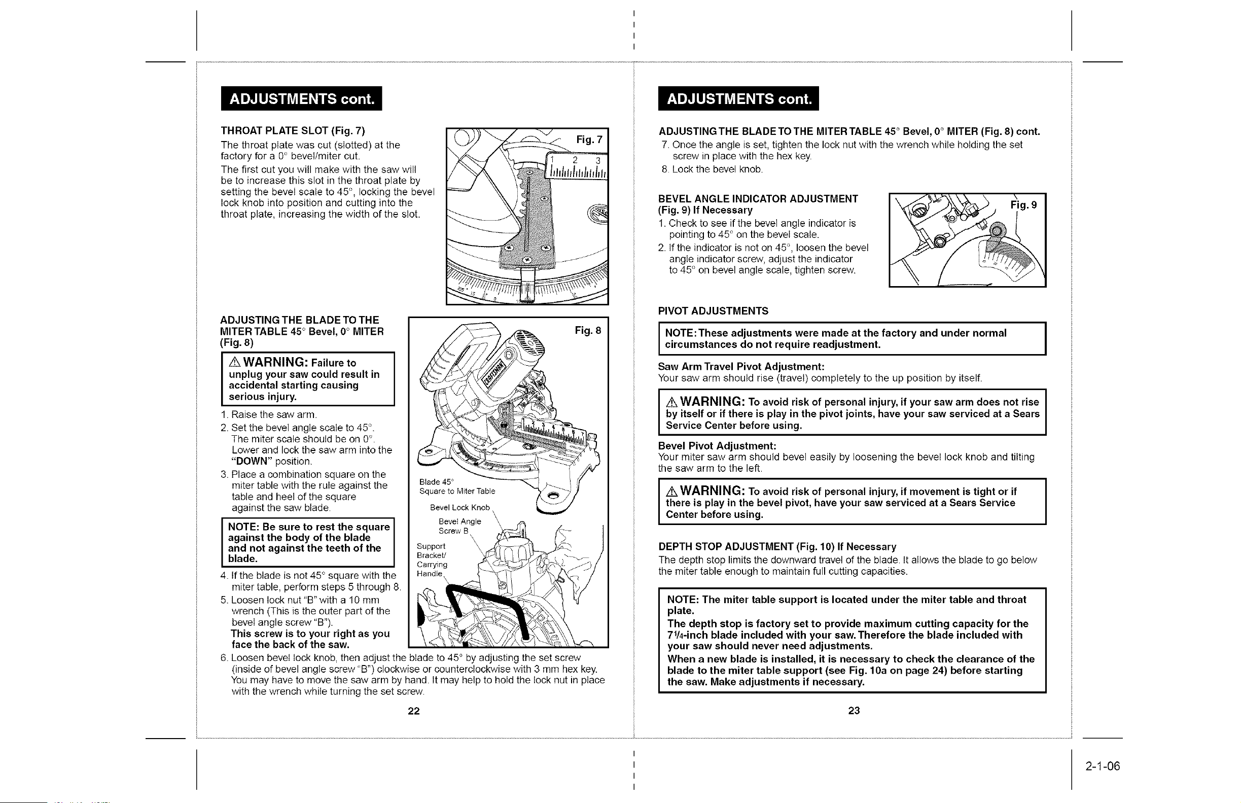
ADJUSTING THE BLADE TO THE
MITER TABLE 45° Bevel, 0° MITER
(Fig. 8)
I WARNING: Failure to I
unplug your saw could result in
accidental starting causing
serious injury.
1. Raise tile saw arm.
2. Set the bevel angle scale to 45 °.
The miter scale should be on 0°.
Lower and lock the saw arm into the
"DOWN" position.
3. Place a combination square on the
miter table with the rule against the
table and heel of the square
against the saw blade.
I NOTE: Be sure to rest the square
against the body of the blade
andblade.nOtaga nst the teeth of the
4. If the blade is not 45° square with the
miter table, perform steps 5 through 8.
5. Loosen lock nut "B" with a 10 mm
wrench (This is the outer part of the
bevel angle screw "B").
This screw is to your right as you
face the back of the saw.
6.
Fig. 8
Loosen bevel lock knob, then adjust the blade to 45° by adjusting the set screw
(inside of bevel angle screw "B") clockwise or counterclockwise with 3 mm hex key.
You may have to move the saw arm by hand. It may help to hold the lock nut in place
with the wrench while turning the set screw.
22
ADJUSTINGTHE BLADETO THE MITER TABLE 45° Bevel, 0° MITER (Fig. 8) cont.
7. Once the angle is set, tighten the lock nut with the wrench while holding the set
screw in place with the hex key.
8. Lock the bevel knob.
BEVEL ANGLE INDICATOR ADJUSTMENT
(Fig. 9) If Necessary
1. Check to see if tile bevel angle indicator is
pointing to 45° on the bevel scale.
2. If the indicator is not on 45°, loosen the bevel
angle indicator screw, adjust the indicator
to 45 ° on bevel angle scale, tighten screw.
PIVOT ADJUSTMENTS
I
NOTE:These adjustments were made at the factory and under normal I
circumstances do not require readjustment.
I
Saw Arm Travel Pivot Adjustment:
Your saw arm should rise (travel) completely to the up position by itself.
I
z WARNING: To avoid risk of personal injury, if your saw arm does not rise I
by itself or if there is play in the pivot joints, have your saw serviced at a Sears
I
Service Center before using.
Bevel Pivot Adjustment:
Your miter saw arm should bevel easily by loosening the bevel lock knob and tilting
the saw arm to the left.
I
WARNING: To avoid risk of personal injury, if movement is tight or if I
there is play in the bevel pivot, have your saw serviced at a Sears Service
I
Center before using.
DEPTH STOP ADJUSTMENT (Fig. 10) If Necessary
The depth stop limits the downward travel of the blade. It allows the blade to go below
the miter table enough to maintain full cutting capacities.
NOTE: The miter table support is located under the miter table and throat
plate.
The depth stop is factory set to provide maximum cutting capacity for the
71/4-inch blade included with your saw. Therefore the blade included with
your saw should never need adjustments,
When a new blade is installed, it is necessary to check the clearance of the
blade to the miter table support (see Fig. 10a on page 24) before starting
the saw. Make adjustments if necessary.
23
I
I
I
I
2-1-06
Loading ...
Loading ...
Loading ...