Loading ...
Loading ...
Loading ...
75
Troubleshooting
TROUBLESHOOTING
Due to our policy of continuous product innovation, some specifications may change without notification.
©LG Electronics U.S.A., Inc., Englewood Cliffs, NJ. All rights reserved. “LG” is a registered trademark of LG Corp.
Troubleshooting Using Error Codes
Refer to the table below and on the next page for error codes that
are generated from the indoor and outdoor units. These codes are
the most common. Your particular system might generate additional
codes not listed here. Please contact LG Support if you see these
types of errors and a simple power cycle has not corrected the issue.
Error Codes
• Error codes are shown on the control boards of indoor unit and
outdoor units, LG Monitoring View (LGMV) Diagnostic Software,
and the SIMs app.
• Error codes are also displayed on the wired wall remote controller,
if installed.
• Error codes indicate different types of unit failures, assists in self-
diagnosis and to track the frequency of occurrence.
• If two or more errors occur simultaneously, the lower error code
number is displayed first.
• After error is resolved, the error code does not display.
Decoding the Error Display
The first and second number on the LED indicates error number.
Example: 21 = LED1 (Green light) 2x blink, LED2 (Red light) 1x blink.
Error Code Nomenclature Definitions
• MICOM: Non-volatile memory chip where unit setup information is
stored.
• EEPROM: Non-volatile memory chip where device identification,
size, and factory defined default component operating parameters
are stored.
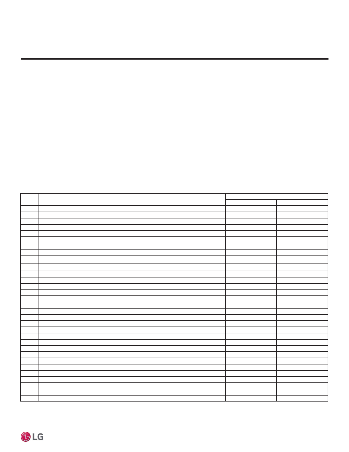
Error Codes
Error
Code
Description
No. of Times Indoor Unit LEDs Blink
LED1 LED2
1 Indoor unit room temperature sensor error 1X -
2 Indoor unit inlet pipe sensor error 2X -
4 Float switch error (optional) 4X -
5 Communication error between indoor unit and outdoor units 5X -
6 Indoor unit outlet pipe sensor error 6X -
9 Indoor unit EEPROM error 9X -
10 Indoor unit BLDC motor fan lock - 1X
12 Indoor unit middle pipe sensor error 2X 1X
21 DC Peak (IPM Fault); Compressor DC voltage was too high
2X 1X
22 Current Transformer2 (CT2) error; Alternating current (AC) input too high
2X 2X
23 DC Link Low Volt 2X 3X
25 AC Low / High Volt 2X 5X
26 DC Comp Position Error (not providing rotation), Locking 2X 6X
27 PSC Fault; Current to inverter compressor between AC and DC converter circuit too high 2X 7X
28 Inverter compressor DC voltage is too high 2X 8X
29 Inverter compressor amperage is too high 2X 9X
31 Current-to-current transformer (CT) thermistor is too low 3X 1X
32 Inverter Compressor Discharge Pipe (D-Pipe) Overheat 3X 2X
40 CT Sensor Error; Thermistor is disconnected or shorted out 4X -
41 D-Pipe Sensor INV is disconnected or shorted out 4X 1X
44 Outdoor Air Sensor is disconnected or shorted out 4X 4X
45 Middle thermistor of outdoor unit condenser coil is disconnected or shorted out 4X 5X
46 Outdoor unit suction line thermistor is disconnected or shorted out 4X 6X
48 Outdoor unit coil outlet (liquid line) thermistor is disconnected or shorted out 4X 8X
53 Communication failure from outdoor unit to indoor unit 5X 3X
60 Outdoor unit printed circuit board (PCB) EEPROM check sum error 6X -
61 Outdoor unit condenser coil temperature is too high 6X 1X
62 Outdoor unit inverter compressor PCB heat sink temperature is too high 6X 2X
63 Condenser coil pipe thermistor temperature is too low 6X 3X
65 Heat sink thermistor has disconnected or has shorted out 6X 5X
67 Outdoor brushless direct current (BLDC) fan motor lock error 6X 7X
Table 25: Single Zone Wall Mounted Indoor Unit Error Codes.
Refer to Service Manuals posted on www.lghvac.com for a full description of all error codes and work-arounds.
Loading ...
Loading ...
Loading ...