Loading ...
Loading ...
Loading ...
56
Single Zone Art Cool Premier Wall Mounted Installation Manual
Due to our policy of continuous product innovation, some specifications may change without notification.
©LG Electronics U.S.A., Inc., Englewood Cliffs, NJ. All rights reserved. “LG” is a registered trademark of LG Corp.
ELECTRICAL SYSTEM INSTALLATION
Connecting Indoor Unit Electrical Wiring
• Verify that main power to the unit is completely off before proceeding with these steps as there is a risk of electrical shock, bodily injury, and / or
death.
• Follow all safety and warning information outlined at the beginning and throughout this manual. Failure to do so will cause electrical shock, bodily
injury, and / or death.
• Follow all safety and warning information outlined at the beginning and throughout this manual. Failure to do so will cause unit failure.
• Connect the communication / connection (power) cable to the indoor unit by matching the terminals on the outdoor unit control board. Verify
the color of the wires at the outdoor unit, along with the terminal numbers, match those for the indoor unit.
• Images are representative; actual appearance will vary.
• Refer to the circuit diagram on the indoor unit bottom cover.
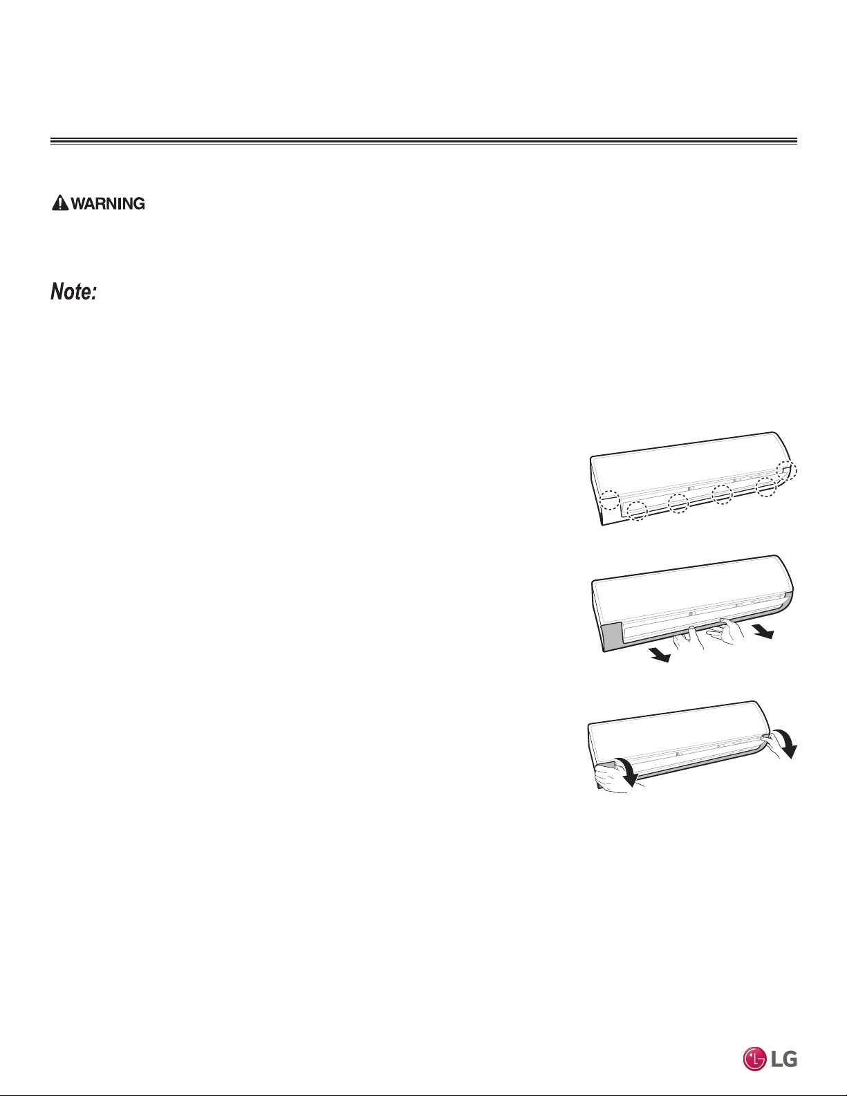
Removing the Indoor Unit Bottom Panel
At this point in the installation procedure, the front panel should already be opened, and the bot-
tom cover should already be removed. If not, follow the steps below.
1. Fully open the front panel.
2. The bottom panel has plastic clips that attach to the indoor unit at several connection points.
The number and position of the connections vary depending on the model of indoor unit.
3. Hold the center of the bottom panel, and pull it towards to disengage the pins, releasing them
from the connection points.
4. Pull both sides of the bottom panel out to release the clips from the connections, being careful
not to damage the bottom panel or scratch the main horizontal vane. Set aside the bottom
panel to re-install after all procedures are complete.
Figure 85: Position of the Bottom Panel
Connection Points.
Figure 86: Releasing the Back of the
Bottom Panel.
Figure 87: Releasing the Sides of the
Bottom Panel.
Preparing the Communication / Connection (Power) Cable and Piping
After the length between the indoor unit and the outdoor unit has been measured, cut the power wiring / communication (connection) cable
and the piping to the proper length:
• Cut the communication (connection) cable 4.9 ft (1.5 m) longer than that of the piping.
• Cut the piping slightly longer than the measurement.
Indoor Unit Electrical Connections
Loading ...
Loading ...
Loading ...