Loading ...
Loading ...
Loading ...
7
INITIAL INSTALLATION INSTRUCTIONS
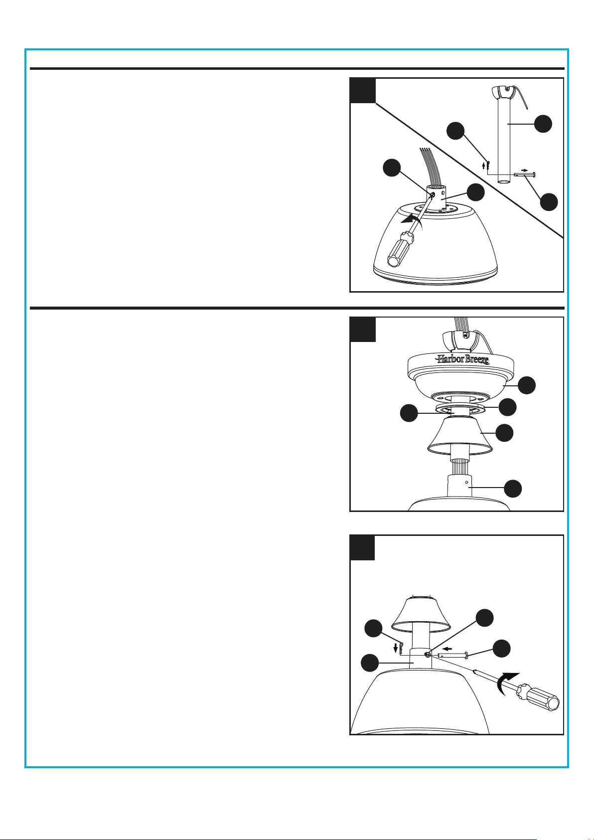
4. Loosen the two coupling screws (N) preassembled in
the coupling (O), but do not remove them. Remove the
hairpin clip (M) and clevis pin (L) from the downrod
assembly (B). Retain for later use.
Note: Make sure to keep loose hardware separate to
avoid confusion during installation.
STANDARD/ANGLE-MOUNTING INSTRUCTIONS
1. Place downrod assembly (B) through canopy (C),
canopy cover (D) and coupling cover (E).
Feed power wires from motor assembly (F) through
downrod assembly (B), then insert downrod assembly (B)
into the coupling (O) on motor assembly (F).
C
D
E
B
O
O
1
2. Align the hole on downrod assembly (B) to hole on the
coupling (O), then re-install clevis pin (L). Re-attach
hairpin clip (M) into clevis pin (L) until it snaps into
place, then tighten the two previously loosened
coupling screws (N).
2
O
N
M
B
L
M
4
L
N
Loading ...
Loading ...
Loading ...