Loading ...
Loading ...
Loading ...
FINAL INSTALLATION INSTRUCTIONS
11
FINAL INSTALLATION INSTRUCTIONS
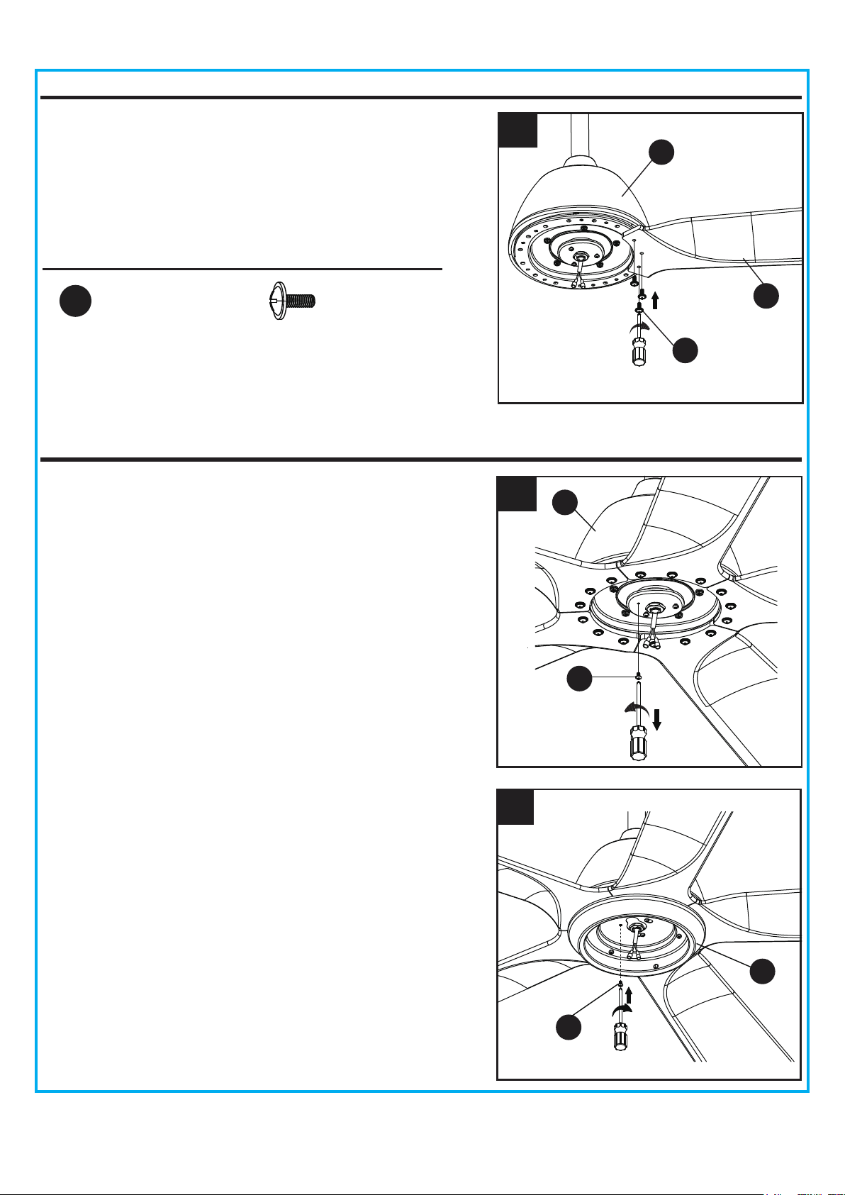
5. Insert the wires with 2 single pin connectors from the
motor assembly through the center hole in the switch
housing (H). Attach the switch housing (H) to the
mounting plate on the motor assembly by placing the
keyhole slots from the switch housing (H) onto the two
protruding mounting screws (Q) heads. Adjust the switch
housing (H) until the screw heads are aligned with the
keyholes, then re-install the mounting screw (Q)
previously removed on step 4. Tighten all mounting
screws (Q) securely.
4
4. Remove one of the mounting screws (Q) on mounting
plate of motor assembly (F), then loosen the other two.
5
F
Q
H
Q
3. Attach blade (G) to the motor assembly (F) with blade
screws (AA) provided.Repeat for the other blades.
Hardware Used
Blade Screw x 15
AA
F
G
3
AA
Loading ...
Loading ...
Loading ...