08-21
PAGE: 1 / 12 PAGE: 2 / 12
LIMITED LIFETIME WARRANTY
Model No.: #
355-0739
To obtain Service, please contact or call Patriot Lighting Service Department:
1-800-267-4427, 8am to 5pm Eastern Time.
The limited lifetime warranty covers this ceiling fan, for residential use by the original purchaser, against defects in
material or workmanship as follows:
If your Patriot Lighting Ceiling Fan motor fails at any time during the lifetime of the original purchaser due to defects in
material or workmanship, we will provide a replacement part free of charge.
If your Fan motor fails at any time within one year after the original date of sale to the original purchaser due to defects
in material or workmanship, we will provide labor to repair the defect, with the exception of take down/reinstallation,
free of charge. The original purchaser will be responsible for all labor costs after this one year period.
If no replacement parts are provided for any part of your Fan motor that fails at any time during your lifetime due to
defects in material or workmanship, we will refund the original purchase price of your Fan.
If your Fan blades, remote controller / pull chain switch, reverse switch, or any accessory, except glass globes and light
bulbs, fails at any time within one year after the original date of purchase due to a defect in material and workmanship,
we will repair or, if we choose, replace the defective blades, switch, or accessory free of charge, with the exception of
take down/reinstallation services.
If the original purchaser ceases to own the Fan, this warranty and any implied warranty, including but not limited to any
implied warranty of merchantability or fitness for a particular purpose, become void. This warranty and any implied
warranty, including but not limited to any implied warranty of merchantability or fitness for a particular purpose, do not
cover glass globes, light bulbs, or finish on any metal portions of the Fan.
This warranty is in lieu of express warranties. The duration of any implied warranty of merchantability or fitness for a
particular purpose, with respect to any Patriot Lighting Ceiling Fan motor, blades, switch, or accessories, is expressly
limited to the period of the express warranty set forth above for such motor, blades, switch, or accessories.
This warranty excludes defects, malfunctions, or failures of any Patriot Lighting Fan that are caused by repairs by
persons not authorized by us, use of parts or accessories not authorized by us, mishandling, improper installation,
modifications or damage to the Fan while in your possession, or unreasonable use, including failure to provide
necessary maintenance.
To obtain service, contact Patriot Lighting Service Department at 1-800-887-6326, 9AM-5PM CST. You will be responsible
for all insurance and freight or other transportation charges to our factory or service center. A copy of sales
receipt is required in order to obtain service. We will return your Fan freight prepaid. Your Fan should be properly
packed to avoid damage in transit, for we will not be responsible for any such damages.
In no event shall Patriot Lighting Fan be liable for consequential or incidental damages.
Some states do not allow the exclusion or limitation of consequential or incidental damages, in which case the above
limitation or exclusion may not apply.
This warranty gives you specific legal rights and you may also have other rights which vary from state to state.
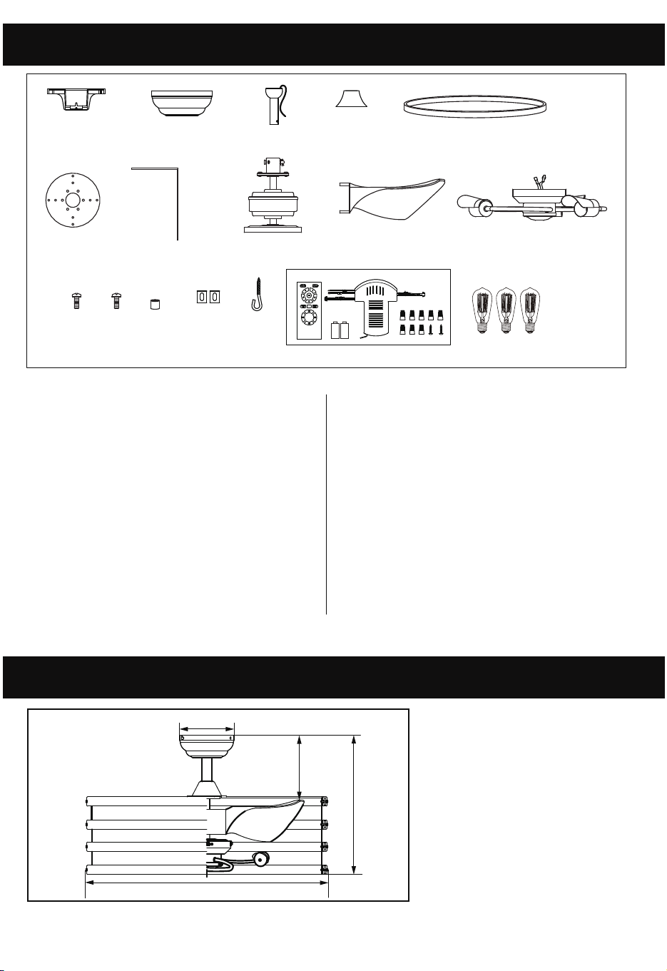
Unpack your fan and check the contents. You should have the following items:
1.) Mounting Bracket
2.) Canopy
4.) Yoke Cover
5.) Circle Ring (4 pcs)
7.) Cover Bracket (4 pcs)
8.) Fan Motor
9.) Fan Blades (3 pcs)
10.) Light Kit
11.) Cover Bracket Screws (8 pcs)
12.) Circle Ring Screws (16 pcs))
Package Contents:
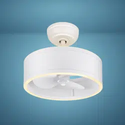
Dimension Reference (Installed with 4” Downrod):
3.) Downrod Assembly (Includes:
Hemisphere, 4” Downrod, Hanger Pin
& Lock Pin)
6.) Retainer Ring
5
8
7
9
3
4
2
1
6
10
11
16
17
14
15
13
12
13.) Circle Ring Nut (16 pcs))
14.) Rubber Gasket
15.) J-Hook)
16.)
Remote Control (Includes: Transmitter,
17.) Bulbs
Receiver, wire nuts, screws &
Batteries)
A. 14 3/4 in. B. 6 7/8 in. C. 25 3/4 in. D. 6 13/16 in.
A
D
B
C
08-21
PAGE: 1 / 12 PAGE: 2 / 12
LIMITED LIFETIME WARRANTY
Model No.: #
355-0739
To obtain Service, please contact or call Patriot Lighting Service Department:
1-800-267-4427, 8am to 5pm Eastern Time.
The limited lifetime warranty covers this ceiling fan, for residential use by the original purchaser, against defects in
material or workmanship as follows:
If your Patriot Lighting Ceiling Fan motor fails at any time during the lifetime of the original purchaser due to defects in
material or workmanship, we will provide a replacement part free of charge.
If your Fan motor fails at any time within one year after the original date of sale to the original purchaser due to defects
in material or workmanship, we will provide labor to repair the defect, with the exception of take down/reinstallation,
free of charge. The original purchaser will be responsible for all labor costs after this one year period.
If no replacement parts are provided for any part of your Fan motor that fails at any time during your lifetime due to
defects in material or workmanship, we will refund the original purchase price of your Fan.
If your Fan blades, remote controller / pull chain switch, reverse switch, or any accessory, except glass globes and light
bulbs, fails at any time within one year after the original date of purchase due to a defect in material and workmanship,
we will repair or, if we choose, replace the defective blades, switch, or accessory free of charge, with the exception of
take down/reinstallation services.
If the original purchaser ceases to own the Fan, this warranty and any implied warranty, including but not limited to any
implied warranty of merchantability or fitness for a particular purpose, become void. This warranty and any implied
warranty, including but not limited to any implied warranty of merchantability or fitness for a particular purpose, do not
cover glass globes, light bulbs, or finish on any metal portions of the Fan.
This warranty is in lieu of express warranties. The duration of any implied warranty of merchantability or fitness for a
particular purpose, with respect to any Patriot Lighting Ceiling Fan motor, blades, switch, or accessories, is expressly
limited to the period of the express warranty set forth above for such motor, blades, switch, or accessories.
This warranty excludes defects, malfunctions, or failures of any Patriot Lighting Fan that are caused by repairs by
persons not authorized by us, use of parts or accessories not authorized by us, mishandling, improper installation,
modifications or damage to the Fan while in your possession, or unreasonable use, including failure to provide
necessary maintenance.
To obtain service, contact Patriot Lighting Service Department at 1-800-887-6326, 9AM-5PM CST. You will be responsible
for all insurance and freight or other transportation charges to our factory or service center. A copy of sales
receipt is required in order to obtain service. We will return your Fan freight prepaid. Your Fan should be properly
packed to avoid damage in transit, for we will not be responsible for any such damages.
In no event shall Patriot Lighting Fan be liable for consequential or incidental damages.
Some states do not allow the exclusion or limitation of consequential or incidental damages, in which case the above
limitation or exclusion may not apply.
This warranty gives you specific legal rights and you may also have other rights which vary from state to state.
Unpack your fan and check the contents. You should have the following items:
1.) Mounting Bracket
2.) Canopy
4.) Yoke Cover
5.) Circle Ring (4 pcs)
7.) Cover Bracket (4 pcs)
8.) Fan Motor
9.) Fan Blades (3 pcs)
10.) Light Kit
11.) Cover Bracket Screws (8 pcs)
12.) Circle Ring Screws (16 pcs))
Package Contents:
Dimension Reference (Installed with 4” Downrod):
3.) Downrod Assembly (Includes:
Hemisphere, 4” Downrod, Hanger Pin
& Lock Pin)
6.) Retainer Ring
5
8
7
9
3
4
2
1
6
10
11
16
17
14
15
13
12
13.) Circle Ring Nut (16 pcs))
14.) Rubber Gasket
15.) J-Hook)
16.)
Remote Control (Includes: Transmitter,
17.) Bulbs
Receiver, wire nuts, screws &
Batteries)
A. 14 3/4 in. B. 6 7/8 in. C. 25 3/4 in. D. 6 13/16 in.
A
D
B
C

PAGE: 3 / 12 PAGE: 4 / 12
NOTE: FOR OPTIMUM QUIETNESS, FULLY ASSEMBLE FAN AND RUN 24 HOURS
TOOLS AND MATERIALS REQUIRED
- Phillips Screwdriver
- Blade Screwdriver
- Step Ladder
- Wire Cutters
- Wiring supplies as required by electrical code.
!
INSTRUCTIONS PERTAINING TO RISK OF FIRE OR INJURY TO PERSONS
READ ALL INSTRUCTIONS
IMPORTANT SAFETY
INSTRUCTIONS
SAVE THESE INSTRUCTIONS
INSTALLATION AND WIRING TO BE IN ACCORDANCE WITH CEC,
NEC, LOCAL ELECTRICAL CODES and ANSI/NFPA 70.
IMPORTANT SAFETY INSTRUCTIONS
WARNING
1. Turn off power at main electrical service box before starting installation.
2. Electrical connections must comply with local code ordinances, national electrical
codes, CEC, NEC and ANSI/NFPA 70.
3. Make sure the installation site you choose allows the fan blades to rotate freely
without any obstructions.
4. When mounting the fan on a ceiling outlet box, use an approved (CSA for Canada
and UL for U.S.) ceiling fan box marked "FOR FAN SUPPORT". Ensure the outlet
box is securely installed in place such that it is able to support at least the fan weight.
5. Total Fan Weight For Reference: 24" approximate 9.3 kgs (20.51 lbs).
1. To reduce the risk of fire or electrical shock, ONLY use model DCQ015 remote
control for optional remote control adaptability.
2.
3. Mount with the lowest moving parts at least 2.10 Meters (7 Feet) above floor or grade
level.
Exploded View Detail
WARNING: RISK OF FIRE, ELECTRIC SHOCK, OR PERSONAL INJURY. THE
FAN IN THIS BOX MAY BE EITHER DIRECTLY SUPPORTED FROM A STRUC-
TURAL FRAMING MEMBER OF A BUILDING AND/OR MAY BE MOUNTED TO
AN OUTLET BOX MARKED ACCEPTABLE FOR FAN SUPPORT OF 35 LBS (15.9
KG) OR LESS. Most outlet boxes commonly used for the support of luminaires may
not be acceptable for fan support and may need to be replaced. Consult a qualified
electrician if in doubt.
Mounting Bracket
Canopy
Downrod
Yoke Cover
Circle Ring
Fan Blades
Light Kit
Fan Motor
Retainer Ring
Cover Bracket
PAGE: 5 / 12 PAGE: 6 / 12
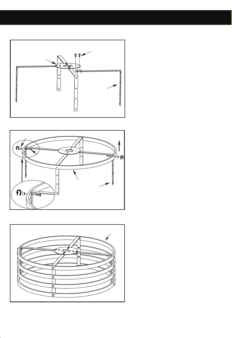
ASSEMBLY INSTRUCTIONS ASSEMBLY INSTRUCTIONS (continued)
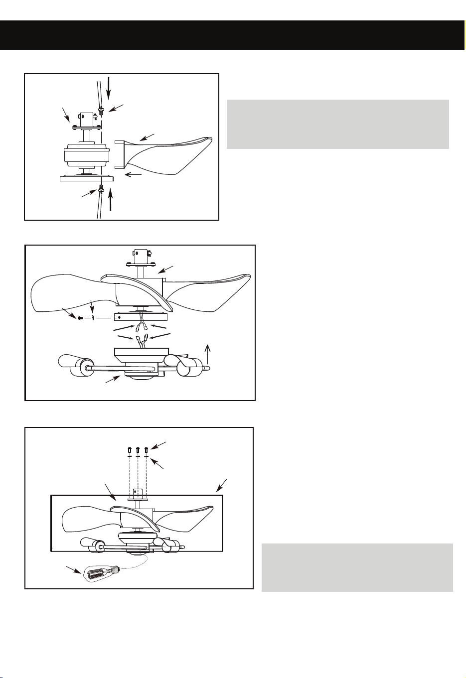
1. ATTACH THE FAN UPPER COVER
2. ATTACH THE FAN BLADES
NOTE: All set screws must be
checked and retightened where necessary,
before and after installation.
DETACHABLE LIGHT KIT
- Remove light kit screws and washers.
- Connect polarized connectors from light
kit to corresponding connectors found
in switch housing.
WARNING: BE SURE TO TURN
OFF POWER BEFORE
INSTALLING.
- Carefully tuck electrical wires back into
switch housing, align light kit with
switch housing and secure with three
light kit screws and washers
- Remove the 6 pre-installed screws
from the yoke.
- Place the fan motor cover on top of the yoke.
Then place the fan upper cover on top of
the fan motor cover while feeding the fan
motor wires through both.
- Re-install the 6 upper cover screws
- Install specified bulb type and wattage.
- Remove the 4 pre-installed screws
& star washers from the fan lower cover.
Align the holes on the fan upper cover
with the holes on the fan lower cover
and reinstall the 4 screws & star washers.
.
WARNING: To reduce the risk of injury
to persons, ensure the fan lower cover
is securely attached on the fan upper
cover before use.
- Attach the fan blades to the fan motor assembly
- Attach the cover bracket to retainer ring
using 2 cover bracket screws as shown.
(Hand tighten)
- Repeat the above for 2nd, 3rd and 4th cover
bracket.
- Attach the 4 circle rings to the cover bracket
from top to bottom using circle ring screws and
circle ring nuts as shown. (Hand tighten)
- When completely assembled adjust the
shape and tighten all screws and nuts.
using the pre-installed screws.
3. LIGHT KIT
4. FAN COVER ASSEMBLY
Lock
washer
Upper
Cover
Bulb
Upper Cover
Screws
Fan Motor
Fan Motor
Motor Screw
Fan Blade
Motor Screw
Lock
washer
Light Kit
Screws
Fan Motor
White Wire
Blue or Red
or Black Wire
Light Kit
Upper Cover
Cover Bracket
Cover Bracket
Retainer Ring
Cover Bracket Screws
Circle Ring
Circle Ring Nut
Circle Ring
Screws
a.
b.
c.
PAGE: 5 / 12 PAGE: 6 / 12
ASSEMBLY INSTRUCTIONS ASSEMBLY INSTRUCTIONS (continued)
1. ATTACH THE FAN UPPER COVER
2. ATTACH THE FAN BLADES
NOTE: All set screws must be
checked and retightened where necessary,
before and after installation.
DETACHABLE LIGHT KIT
- Remove light kit screws and washers.
- Connect polarized connectors from light
kit to corresponding connectors found
in switch housing.
WARNING: BE SURE TO TURN
OFF POWER BEFORE
INSTALLING.
- Carefully tuck electrical wires back into
switch housing, align light kit with
switch housing and secure with three
light kit screws and washers
- Remove the 6 pre-installed screws
from the yoke.
- Place the fan motor cover on top of the yoke.
Then place the fan upper cover on top of
the fan motor cover while feeding the fan
motor wires through both.
- Re-install the 6 upper cover screws
- Install specified bulb type and wattage.
- Remove the 4 pre-installed screws
& star washers from the fan lower cover.
Align the holes on the fan upper cover
with the holes on the fan lower cover
and reinstall the 4 screws & star washers.
.
WARNING: To reduce the risk of injury
to persons, ensure the fan lower cover
is securely attached on the fan upper
cover before use.
- Attach the fan blades to the fan motor assembly
- Attach the cover bracket to retainer ring
using 2 cover bracket screws as shown.
(Hand tighten)
- Repeat the above for 2nd, 3rd and 4th cover
bracket.
- Attach the 4 circle rings to the cover bracket
from top to bottom using circle ring screws and
circle ring nuts as shown. (Hand tighten)
- When completely assembled adjust the
shape and tighten all screws and nuts.
using the pre-installed screws.
3. LIGHT KIT
4. FAN COVER ASSEMBLY
Lock
washer
Upper
Cover
Bulb
Upper Cover
Screws
Fan Motor
Fan Motor
Motor Screw
Fan Blade
Motor Screw
Lock
washer
Light Kit
Screws
Fan Motor
White Wire
Blue or Red
or Black Wire
Light Kit
Upper Cover
Cover Bracket
Cover Bracket
Retainer Ring
Cover Bracket Screws
Circle Ring
Circle Ring Nut
Circle Ring
Screws
a.
b.
c.
PAGE: 7 / 12
PAGE: 8 / 12
ASSEMBLY INSTRUCTIONS (continued) ASSEMBLY INSTRUCTIONS (continued)
A
B
SUPPLY CIRCUIT 120V
BOX
OUTLET
Fan Motor
BLUE
WHITE
WHITE
BLACK
BLUE
WHITE
BLUE
WHITE
RED
PINK
GREY
GREEN
GREEN
GREEN
WHITE
BLACK
GROUND
GROUND TO DOWNROD
GREEN
RED
PURPLE
GREY
RECEIVER
Make the following wire connections using the wire nuts supplied.
a To the household supply wires
Connect the following 4 GREEN wires to the GREEN or bare copper supply wire.
1. GREEN wire from the downrod
2. GREEN wire from the receiver
3. GREEN wire from the motor
4. GREEN wire from the mounting bracket
- Connect BLACK receiver unit wire to BLACK supply wire.
- Connect WHITE receiver unit wire to WHITE supply wire.
b To the light wires
Connect WHITE receiver wire to the WHITE wire from motor.
Connect BLUE receiver wire to the BLUE wire from motor.
c To the fan wires
Connect RED receiver wire to the RED wire from motor.
Connect GREY receiver wire to the GREY wire from motor.
Connect PINK receiver wire to the PURPLE wire from motor.
- After making the wire connections, ensure the wires should be spread
apart with the grounded conductor and the equipment-grounding
conductor on one side of the outlet box and the ungrounded conductor
on the other side of the outlet box.
- Ensure the connections after being made are turned upward and
pushed carefully up into the outlet box.
- Make sure no bare wire is visible at the wire nuts.
- Use the cable ties supplied to tighten each group of wires for easy installation.
Cable Tie
Cable Tie
Cable Tie
7. ELECTRICAL HOOK-UP
NOTE: Once ground
wires are connected,
carefully tuck all
wires and wire nuts
into the metal outlet
box making sure that
the wires are clear
of the hemisphere
and downrod when
positioned in
mounting bracket.
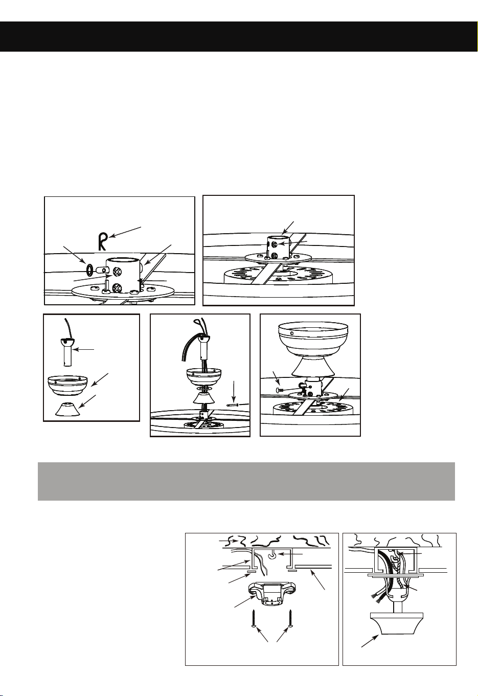
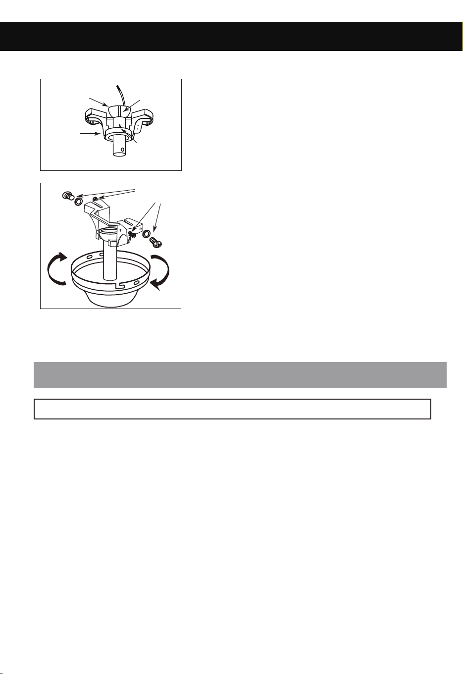
- Separate mounting bracket from canopy by removing screws.
- Remove cotter pin and bolt from yoke.
- Loosen the jam screws in the yoke until they are flush with the inside surface of the yoke.
- Obtain downrod, canopy and yoke cover.
- Place downrod through the canopy and yoke cover.
- Route wires exiting motor through yoke cover, canopy and downrod, insert downrod into yoke.
- Insert bolt through hole in shaft and downrod. Be careful not to damage or cut the fan wires.
- Place flat washer on the end of the bolt. Secure with cotter pin through hole
in the end of the bolt.
- Secure downrod in position by tightening jam screws. Slide yoke cover down so it is flush
with the upper cover.
5. MOUNTING
Motor
Bolt
6. INSTALL MOUNTING BRACKET
- Install J-Hook through center of outlet box and into the wooden joist.
- Attach rubber gaskets to mounting bracket and then secure to outlet box.
- Hang the safety cable from
the fan motor onto the J-hook.
Canopy
WARNING: To Reduce The Risk Of Fire, Electric Shock, Or Personal Injury, Mount
To UL/CSA Listed Outlet Box Marked Acceptable For Fan Support And Use Mounting
Screws Provided With The Outlet Box.
Yoke
Jam
Screw
Jam
Screw
Downrod
Canopy
Yoke
Cover
J-Hook
Safety
Cable
Wood
Joist
Outlet
Box
Rubber
Gasket
Mounting
Bracket
Outlet box screws
(not provided)
Ceiling
J-Hook
Bolt
Flat
Washer
Cotter Pin
Yoke
Jam
Screw
a.
b.
c.
d.
e.
PAGE: 7 / 12
PAGE: 8 / 12
ASSEMBLY INSTRUCTIONS (continued) ASSEMBLY INSTRUCTIONS (continued)
A
B
SUPP CIRCUIT 120V
BOX
OUTLET
Fan Motor
BLUE
WHITE
WHITE
BLACK
BLUE
WHITE
BLUE
WHITE
RED
PINK
GREY
GREEN
GREEN
GREEN
WHITE
BLACK
GROUND
GROUND TO DOWNROD
GREEN
RED
PURPLE
GREY
RECEIVER
-
Cable Tie
Cable Tie
Cable Tie
7. ELECTRICAL HOOK-UP
NOTE: Once ground
wires are connected,
carefully tuck all
wires and wire nuts
into the metal outlet
box making sure that
the wires are clear
of the hemisphere
and downrod when
positioned in
mounting bracket.
- Separate mounting bracket from canopy by removing screws.
- Remove cotter pin and bolt from yoke.
- Loosen the jam screws in the yoke until they are flush with the inside surface of the yoke.
- Obtain downrod, canopy and yoke cover.
- Place downrod through the canopy and yoke cover.
- Route wires exiting motor through yoke cover, canopy and downrod, insert downrod into yoke.
- Insert bolt through hole in shaft and downrod. Be careful not to damage or cut the fan wires.
- Place flat washer on the end of the bolt. Secure with cotter pin through hole
in the end of the bolt.
- Secure downrod in position by tightening jam screws. Slide yoke cover down so it is flush
with the upper cover.
5. MOUNTING
Motor
Bolt
6. INSTALL MOUNTING BRACKET
- Install J-Hook through center of outlet box and into the wooden joist.
- Attach rubber gaskets to mounting bracket and then secure to outlet box.
- Hang the safety cable from
the fan motor onto the J-hook.
Canopy
WARNING: To Reduce The Risk Of Fire, Electric Shock, Or Personal Injury, Mount
To UL/CSA Listed Outlet Box Marked Acceptable For Fan Support And Use Mounting
Screws Provided With The Outlet Box.
Yoke
Jam
Screw
Jam
Screw
Downrod
Canopy
Yoke
Cover
J-Hook
Safety
Cable
Wood
Joist
Outlet
Box
Rubber
Gasket
Mounting
Bracket
Outlet box screws
(not provided)
Ceiling
J-Hook
Bolt
Flat
Washer
Cotter Pin
Yoke
Jam
Screw
a.
b.
c.
d.
e.

PAGE: 7 / 12
PAGE: 8 / 12
ASSEMBLY INSTRUCTIONS (continued) ASSEMBLY INSTRUCTIONS (continued)
A
B
SUPPLY CIRCUIT 120V
BOX
OUTLET
Fan Motor
BLUE
WHITE
WHITE
BLACK
BLUE
WHITE
BLUE
WHITE
RED
PINK
GREY
GREEN
GREEN
GREEN
WHITE
BLACK
GROUND
GROUND TO DOWNROD
GREEN
RED
PURPLE
GREY
RECEIVER
Make the following wire connections using the wire nuts supplied.
a To the household supply wires
Connect the following 4 GREEN wires to the GREEN or bare copper supply wire.
1. GREEN wire from the downrod
2. GREEN wire from the receiver
3. GREEN wire from the motor
4. GREEN wire from the mounting bracket
- Connect BLACK receiver unit wire to BLACK supply wire.
- Connect WHITE receiver unit wire to WHITE supply wire.
b To the light wires
Connect WHITE receiver wire to the WHITE wire from motor.
Connect BLUE receiver wire to the BLUE wire from motor.
c To the fan wires
Connect RED receiver wire to the RED wire from motor.
Connect GREY receiver wire to the GREY wire from motor.
Connect PINK receiver wire to the PURPLE wire from motor.
- After making the wire connections, ensure the wires should be spread
apart with the grounded conductor and the equipment-grounding
conductor on one side of the outlet box and the ungrounded conductor
on the other side of the outlet box.
- Ensure the connections after being made are turned upward and
pushed carefully up into the outlet box.
- Make sure no bare wire is visible at the wire nuts.
- Use the cable ties supplied to tighten each group of wires for easy installation.
Cable Tie
Cable Tie
Cable Tie
7. ELECTRICAL HOOK-UP
NOTE: Once ground
wires are connected,
carefully tuck all
wires and wire nuts
into the metal outlet
box making sure that
the wires are clear
of the hemisphere
and downrod when
positioned in
mounting bracket.
- Separate mounting bracket from canopy by removing screws.
- Remove cotter pin and bolt from yoke.
- Loosen the jam screws in the yoke until they are flush with the inside surface of the yoke.
- Obtain downrod, canopy and yoke cover.
- Place downrod through the canopy and yoke cover.
- Route wires exiting motor through yoke cover, canopy and downrod, insert downrod into yoke.
- Insert bolt through hole in shaft and downrod. Be careful not to damage or cut the fan wires.
- Place flat washer on the end of the bolt. Secure with cotter pin through hole
in the end of the bolt.
- Secure downrod in position by tightening jam screws. Slide yoke cover down so it is flush
with the upper cover.
5. MOUNTING
Motor
Bolt
6. INSTALL MOUNTING BRACKET
- Install J-Hook through center of outlet box and into the wooden joist.
- Attach rubber gaskets to mounting bracket and then secure to outlet box.
- Hang the safety cable from
the fan motor onto the J-hook.
Canopy
WARNING: To Reduce The Risk Of Fire, Electric Shock, Or Personal Injury, Mount
To UL/CSA Listed Outlet Box Marked Acceptable For Fan Support And Use Mounting
Screws Provided With The Outlet Box.
Yoke
Jam
Screw
Jam
Screw
Downrod
Canopy
Yoke
Cover
J-Hook
Safety
Cable
Wood
Joist
Outlet
Box
Rubber
Gasket
Mounting
Bracket
Outlet box screws
(not provided)
Ceiling
J-Hook
Bolt
Flat
Washer
Cotter Pin
Yoke
Jam
Screw
a.
b.
c.
d.
e.
PAGE: 7 / 12
PAGE: 8 / 12
ASSEMBLY INSTRUCTIONS (continued) ASSEMBLY INSTRUCTIONS (continued)
A
B
SUPP CIRCUIT 120V
BOX
OUTLET
Fan Motor
BLUE
WHITE
WHITE
BLACK
BLUE
WHITE
BLUE
WHITE
RED
PINK
GREY
GREEN
GREEN
GREEN
WHITE
BLACK
GROUND
GROUND TO DOWNROD
GREEN
RED
PURPLE
GREY
RECEIVER
-
Cable Tie
Cable Tie
Cable Tie
7. ELECTRICAL HOOK-UP
NOTE: Once ground
wires are connected,
carefully tuck all
wires and wire nuts
into the metal outlet
box making sure that
the wires are clear
of the hemisphere
and downrod when
positioned in
mounting bracket.
- Separate mounting bracket from canopy by removing screws.
- Remove cotter pin and bolt from yoke.
- Loosen the jam screws in the yoke until they are flush with the inside surface of the yoke.
- Obtain downrod, canopy and yoke cover.
- Place downrod through the canopy and yoke cover.
- Route wires exiting motor through yoke cover, canopy and downrod, insert downrod into yoke.
- Insert bolt through hole in shaft and downrod. Be careful not to damage or cut the fan wires.
- Place flat washer on the end of the bolt. Secure with cotter pin through hole
in the end of the bolt.
- Secure downrod in position by tightening jam screws. Slide yoke cover down so it is flush
with the upper cover.
5. MOUNTING
Motor
Bolt
6. INSTALL MOUNTING BRACKET
- Install J-Hook through center of outlet box and into the wooden joist.
- Attach rubber gaskets to mounting bracket and then secure to outlet box.
- Hang the safety cable from
the fan motor onto the J-hook.
Canopy
WARNING: To Reduce The Risk Of Fire, Electric Shock, Or Personal Injury, Mount
To UL/CSA Listed Outlet Box Marked Acceptable For Fan Support And Use Mounting
Screws Provided With The Outlet Box.
Yoke
Jam
Screw
Jam
Screw
Downrod
Canopy
Yoke
Cover
J-Hook
Safety
Cable
Wood
Joist
Outlet
Box
Rubber
Gasket
Mounting
Bracket
Outlet box screws
(not provided)
Ceiling
J-Hook
Bolt
Flat
Washer
Cotter Pin
Yoke
Jam
Screw
a.
b.
c.
d.
e.
PAGE: 9 / 12
LY INSTRUCTIONS
PAGE: 10 / 12
ASSEMBLY INSTRUCTIONS (continued) ASSEMBLY INSTRUCTIONS (continued)
YLBMESSA NAF GNITNUOM .8
WARNING: Ensure that all connections, set screws and screws are securely tightened.
(B)
(B)
(A)
Washers
Hemisphere
Mounting
Bracket
NOTE: When installing fan on sloped ceiling, make sure tab on hanger bracket faces
towards the top of the slope. Depending on the slope, a longer downrod may be required to
prevent fan blades from hitting the ceiling.
WARNING: Failure to seat tab in groove could cause damage to electrical wires and
possible shock or fire hazard.
Groove
Tab
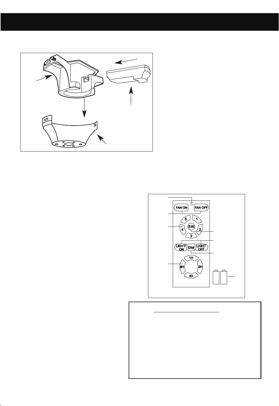
- Carefully rotate fan assembly until groove in
hemisphere locks over tab of canopy assembly.
- Place two screws and washers on mounting
bracket (marked B on diagram) which
correspond with slots in canopy.
Screw in two turns.
- Position canopy to mounting bracket aligning slots
to screws (marked B on diagram) then turn to lock.
- Position and tighten the two screws and washers
(marked A on diagram) then insert the remaining
two screws and tighten (marked B on diagram).
C
- Push all connected wires up into ceiling box.
- Position the receiver into the canopy as shown direction.
Receiver
Mounting
Bracket
Canopy
- When installing
the canopy, ensure
the antenna is not
pressed by the canopy.
FUNCTION INSTRUCTION OF TRANSMITTER
D
①
②
③
④
⑥
⑤
⑦
⑧
- Learning code and matching mode is used between transmitter and receiver.
- Turn "ON" the supply power. Within 30 seconds, press "FAN ON"
button on the transmitter for 5 seconds.
Transmitter and receiver are connected
after hearing a long “beep".
- If the transmitter cannot control the fan,
check to ensure all wiring connections
are properly connected according to the
instruction manual. Check to ensure the
batteries are in the right position. Check
whether there are any similar remote
controls in use nearby. Check whether
they work with the same frequency.
- Low voltage of battery will affect the
sensitivity of the transmitter. The indicator
light will flash when battery voltage
is low. Replace the batteries for
better performance.
- Take out the batteries from the
transmitter when leaving unused
for long periods of time.
REMOTE CONTROL
①
②
Two 1.5V AAA Batteries
LED indicated light
ON/OFF the fan
③Speed of the fan (①low speed - ⑤high speed)
④
Timing control of the fan
Short press: ON/OFF the light
⑤
⑥
Direction of the fan (reverse switch)
⑦
Long press(hold for 3 seconds): Dimming
⑧
PAGE: 9 / 12
LY INSTRUCTIONS
PAGE: 10 / 12
ASSEMBLY INSTRUCTIONS (continued) ASSEMBLY INSTRUCTIONS (continued)
YLBMESSA NAF GNITNUOM .8
WARNING: Ensure that all connections, set screws and screws are securely tightened.
(B)
(B)
(A)
Washers
Hemisphere
Mounting
Bracket
NOTE: When installing fan on sloped ceiling, make sure tab on hanger bracket faces
towards the top of the slope. Depending on the slope, a longer downrod may be required to
prevent fan blades from hitting the ceiling.
WARNING: Failure to seat tab in groove could cause damage to electrical wires and
possible shock or fire hazard.
Groove
Tab
- Carefully rotate fan assembly until groove in
hemisphere locks over tab of canopy assembly.
- Place two screws and washers on mounting
bracket (marked B on diagram) which
correspond with slots in canopy.
Screw in two turns.
- Position canopy to mounting bracket aligning slots
to screws (marked B on diagram) then turn to lock.
- Position and tighten the two screws and washers
(marked A on diagram) then insert the remaining
two screws and tighten (marked B on diagram).
C
- Push all connected wires up into ceiling box.
- Position the receiver into the canopy as shown direction.
Receiver
Mounting
Bracket
Canopy
- When installing
the canopy, ensure
the antenna is not
pressed by the canopy.
FUNCTION INSTRUCTION OF TRANSMITTER
D
①
②
③
④
⑥
⑤
⑦
⑧
- Learning code and matching mode is used between transmitter and receiver.
- Turn "ON" the supply power. Within 30 seconds, press "FAN ON"
button on the transmitter for 5 seconds.
Transmitter and receiver are connected
after hearing a long “beep".
- If the transmitter cannot control the fan,
check to ensure all wiring connections
are properly connected according to the
instruction manual. Check to ensure the
batteries are in the right position. Check
whether there are any similar remote
controls in use nearby. Check whether
they work with the same frequency.
- Low voltage of battery will affect the
sensitivity of the transmitter. The indicator
light will flash when battery voltage
is low. Replace the batteries for
better performance.
- Take out the batteries from the
transmitter when leaving unused
for long periods of time.
REMOTE CONTROL
①
②
Two 1.5V AAA Batteries
LED indicated light
ON/OFF the fan
③Speed of the fan (①low speed - ⑤high speed)
④
Timing control of the fan
Short press: ON/OFF the light
⑤
⑥
Direction of the fan (reverse switch)
⑦
Long press(hold for 3 seconds): Dimming
⑧

PAGE: 11 / 12
To clean the fixture, turn off the power, wait for it to cool, and wipe the fixture
with a clean, soft cloth.
ASSEMBLY INSTRUCTIONS
CARE AND MAINTENANCE
TROUBLESHOOTING
- Check wiring connections to fan.
- Check fuses and circuit breakers.
- Check wiring connections in switch housing.
CAUTION: Turn power off for last two items.
- Check to make sure that all screws in motor housing are snug.
- Check to make sure that blade bracket screws are tight.
- Check to make sure that wire nuts in switch housing
are not rattling against wall of switch housing.
- If fan has a light kit make sure switch housing
screws and set screws are tight.
- Some fan motors are sensitive to signals from solid state
variable controls. If solid state controller is used, change to
an alternative control. (See a representative for a list of
available controls.)
- Allow a 24 hour break in period to eliminate most noises.
- Check that all blades are screwed firmly into blade brackets.
- Check that blade brackets are secured firmly to motor.
- Check distance from tip of blades to ceiling.
- Check distance between blade tip to blade tip. All
measurements should be equal. Loosen blade screws and
position blade until even then re-tighten.
- Check that the downrod hemisphere notch is engaged in canopy.
- Check to make sure that jam screws in downrod are tightened.
- Make sure canopy and mounting bracket are tightened securely
to wooden joist.
- Make sure warpage has not occurred in wooden blades. If so,
contact the customer service department for replacement parts.
TROUBLE SUGGESTIONS
1. Fan will not start
2. Fan sounds noisy
3. Fan wobbles or
shakes excessively.
PAGE: 12 / 12
This equipment has been tested and found to comply with the limits for
a Class B digital device, pursuant to Part 15 of the FCC Rules. These
limits are designed to provide reasonable protection against harmful
interference in a residential installation. This equipment generates,
uses and can radiate radio frequency energy and, if not installed and
used in accordance with the instructions, may cause harmful
interference to radio communications. However, there is no guarantee
that interference will not occur in a particular installation. If this
equipment does cause harmful interference to radio or television
reception, which can be determined by turning the equipment off and
on, the user is encouraged to try to correct the interference by one or
more of the following measures:
-- Reorient or relocate the receiving antenna.
-- Increase the separation between the equipment and receiver.
-- Connect the equipment into an outlet on a circuit different from that
to which the receiver is connected.
-- Consult the dealer or an experienced radio/TV technician for help.
CAUTION:
Any changes or modifications not expressly approved by the grantee
of this device could void the user’s authority to operate the equipment.
This device complies with Part 15 of the FCC Rules. Operation is
subject to the following two conditions: (1) This device may not cause
harmful interference, and (2) this device must accept any interference
received, including interference that may cause undesired operation.
This device contains licence-exempt transmitter(s)/receiver(s)
that comply with Innovation, Science and Economic Development
Canada’s licence-exempt RSS(s). Operation is subject to the
following two conditions:
1. This device may not cause interference.
2. This device must accept any interference, including interference
that may cause undesired operation of the device.
Supplier's Declaration of Conformity
47 CFR § 2.1077 Compliance Information
Unique Identifier: PATRIOT
Responsible Party
CanarmInc.
709 East Main Street, Teutopolis, Illinois, USA 62467
1.800.267.4427