[///:/ FTS
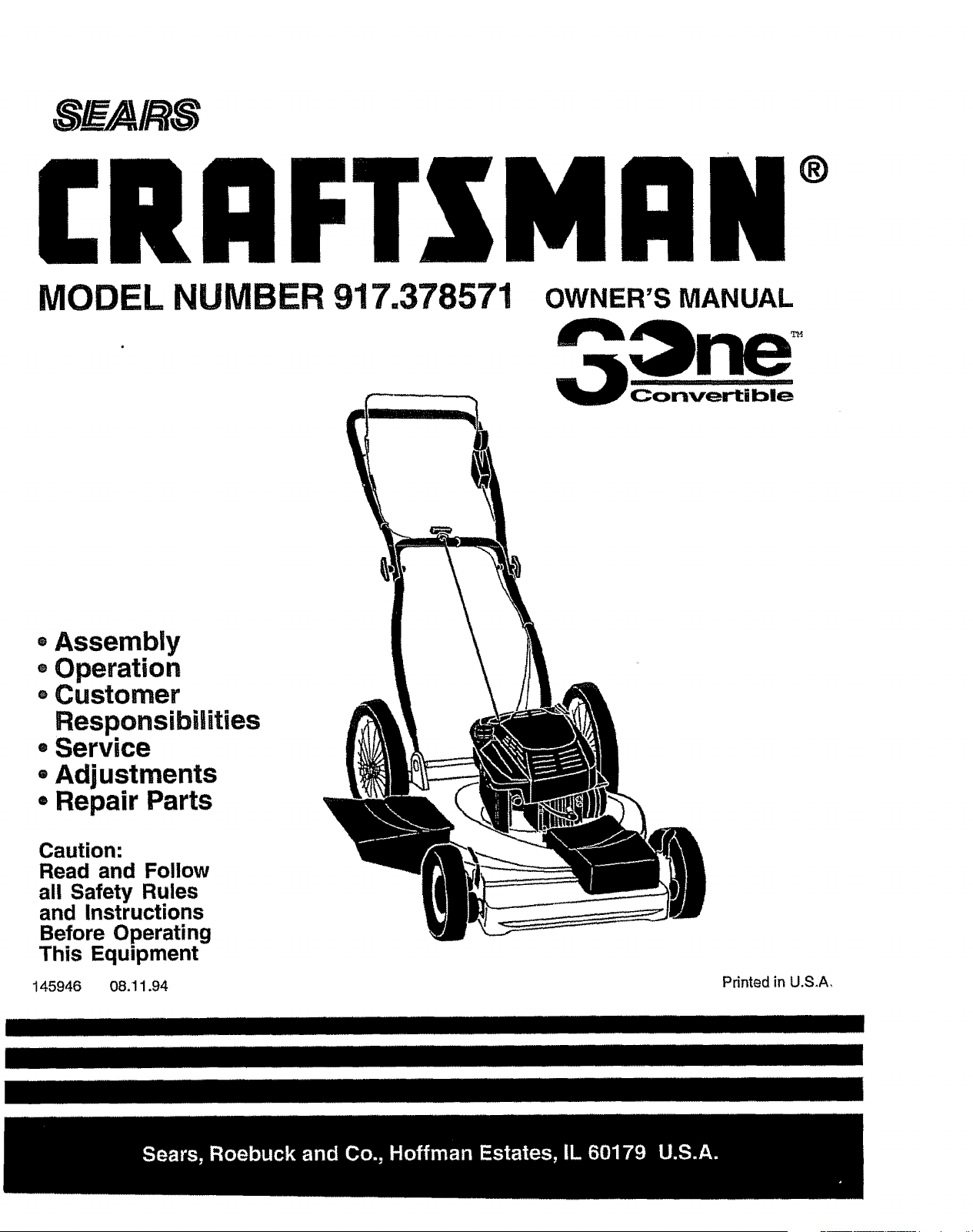
MODEL NUMBER 917.378571
®
OWNER'S MANUAL
Convertible
=Assembly
®Operation
• Customer
Responsibilities
, Service
• Adjustments
° Repair Parts
Caution:
Read and Follow
all Safety Rules
and instructions
Before Operating
This Equipment
145946 08.11.94
Printed in U.S.A,
IIIIIIIIIIIIIIIIIIIIIIIIIIIIIIIIIIIIII IIIIIIIIIIIIIIIII IIII III I IIIIIIIIIIIIIIIIIIIIIIIIIIII IIIIII
TY UL
CAUTION: ALWAYS DISCONNECT SPARK PLUGWIRE AND PLACE WiRE WHERE ITCANNOT CONTACT SPARK &
PLUG TO PREVENT ACCIDENTAL STARTING WHEN SETTING UP, TRANSPORTING, ADJUSTING OR MAKING
REPAIRS. iMPORTANT
SAFETY STANDARDS REQUIRE OPERATOR PRESENCE CONTROLS TO MINIMIZE THE RISK OF INJURY. YOUR UNIT IS EQUIPPED WITH
SUCH CONTROLS. DO NOT ATTEMPT TO DEFEAT THE FUNCTION OF THE OPERATOR PRESENCE CONTROLS UNDER ANY CIRCUM-
STANCES_
TRAINING:
• Read this operator's manual carefully, Become familiar with
the controls and know how to operate your mower properly,
Learn how to quickly stop mower,,
= Do not allow children to use your mower. Never allowadults
to use mower without proper instructions.
• Keep the area of operation clear of aU persons, especially
small children and pets,
° Use mower only as the manufacturer intended and as de-
scribed in this manual,
°
Do not operate mower if it has been dropped or damaged in
any manner. Always have damage repaired before using
your mower.
Do not use accessory attachments that are notrecommended
by the manufacturer,, Use of such attachments may be
hazardous.
The blade turns when the engine is running.
PREPARATION:
- Always thoroughly cileck the area to be mowed and clear it of
alt stones, sticks, wires, bones, and other foreign objects.
These objects will be thrown by the blade and can cause
severe injury..
• Always wear safety glasses or eye shields when starting and
while using your mower,.
° Dress propedy. Do not operate mower when barefoot or
wearing open sandals.. Wear=only solid shoes with good
traction when mowing.
° Check fuel tank before starting engine.. Do not fitl gas tank
indoors, when the engine is running or when the engine ishot.
Allow the engine to cool for several minutes before filling the
gas tank, Clean off any spilled gasoline before starting the
engine.
o Always make wheel height adjustments before startingyour
mower. Never attempt to do this while the engine is running_
• Mow only in daylight or good artificial light.
OPERATION:
• Keep your eyes and mind on your mower and the area being
cut. Do not let other interests distract you,
° Do not mow wet or slippery grass. Never run whUe operating
your mower. Always be sure of your footing- keep a firm hold
on the handles and walk.
• Do not put hands or feet near or under rotating parts. Keep
clear of the discharge opening at all times.
• Always stop the engine whenever you leave or are not using
your mower, or before crossing driveways, walks, roads, and
any gravel-covered areas.
° Never direct discharge of matedal toward bystanders nor
allow anyone near the mower while you are operating it.
° Before cleaning, inspecting, or repairing your mower, stop
the engine and make absolutely sure the blade and all
moving parts have stopped. Then disconnect the spark plug
wire and keep it away from the spark plug to prevent acciden-
tal starting.
° Do not continueto run your mower if you hit a foreign object,.
Follow the procedure outlined above, then repair any dam-
age before restarting and operating you mower,.
° Do not change the governor settings or overspeed the
engine,, Engine damage or personal injury may resulL
° Do not operate your mower'if it vibrates abnormally,, Exces-
sive vibration is an indication of damage; stop the engine,
safely check for the cause ofvibration and repair as required,
,, Do not run the engine indoors. Exhaust fumes are danger-
OUS,
- Never cut grass by pulling the mower towards you. Mow
across the face of slopes, never up and down or you might
lose your footing. Do not mowexcessivefy steep slopes. Use
caution when operating the mower on uneven terrain orwhen
changing directions - maintain good footing.
= Never operate your mower without proper guards, plates,
grass catcher or other safety devices in place,
MAINTENANCE AND STORAGE:
° Check the blade and the engine mounting bolts often to be
sure they are tightened properly,,
• Check all bolts, nuts and screws at frequent intervals for
proper tightness to be sure mower is in safe working condi-
tion.
- Keep all safety devices in place and working,
• To reduce fire hazard, keep tile engine free of grass, leaves
or excessive grease and oil.
= Check grass catcher often for deterioration and wear and
replace wom bags. Use only replacement bags that are
recommended by and comply with specifications of the
manufacturer of your mower..
° Always keep a sharp blade on your mower.
° Allow engine to coot before storing in any enclosure.
° Never store mower with fuel in the tank inside a building
where fumes may reach an open flame or an ignition source
such as a hot water heater, space heater, clothes dryer, etc.
i i i i ull ii ii lllllllll,i : : : ......... i llll llllllll _ i i ii ii llllllllllllill i
,_ LOOK FOR THIS SYMBOL TO POINT OUT IMPORTANT SAFETY PRECAUTIONS.
! _ IT MEANS-ATTENTION!t! BECOME ALERT,,, YOUR SAFETY IS INVOLVED. I
2
CONGRATULATIONS on your purchase of a Sears Lawn
Mower. It has been designed, engineered and manufac-
tured to give you the best possible dependability and
performance.
Should you experience any problem you cannot easily
remedy, please contact your nearest Sears Authorized
Service Center/Department, We have competent, welF
trained technicians and the proper tools to service or repair
this lawn mower.
Please read and retain this manual. The instructions will
enable you to assemble and maintain your lawn mower
_roperly. Always observe the "SAFETY RULES".
MODEL
NUMBER
SERIAL
NUMBER
917.378571
DATEOF PURCHASE
THE MODELAND SERIAL NUMBERSWILL BE FOUND
ON A DECAL ATTACHED TO THE REAR OF THE
LAWN MOWER HOUSING
YOU SHOULD RECORD BOTH SERIAL NUMBER AND
DATE OF PURCHASE AND KEEP IN A SAFE PLACE
FOR FUTURE REFERENCE°
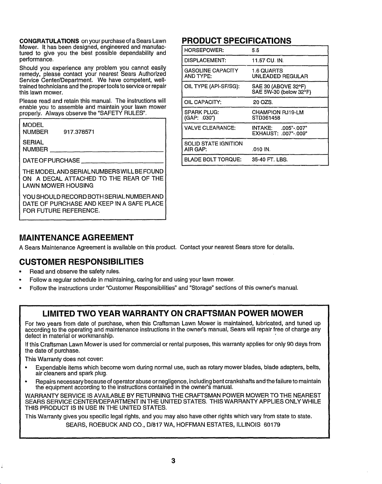
PRODUCT SPECIFICATIONS
HORSEPOWER: 5_5
DISPLACEMENT: tl.57 CU_IN.
GASOLINECAPACITY 1,6 QUARTS
ANDTYPE: UNLEADEDREGULAR
OIL TYPE (API-SFtSG): SAE 30 (ABOVE 32°F)
SAE 5W-30 (below 32°F)
OIL CAPACITY: 20 OZSo
SPARKPLUG: CHAMPION RJ19-LM
(GAP: .030") STD36145B
VALVECLEARANCE: INTAKE: .005"-,007"
EXHAUST: ,,007"-,,009"
SOLIDSTATE IGNITION
AIR GAP: ,010 IN
BLADEBOt.TTORQUE: 35-40 FT. LBS.
MAINTENANCE AGREEMENT
A Sears Maintenance Agreement is available on this producL Contact your nearest Sears store for details,
CUSTOMER RESPONSIBILITIES
. Read and observe the safety rules.
o Follow a regular schedule in maintaining, caring for and using your lawn mower,
• Follow the instructionsunder "Customer Responsibilities"and "Storage" sections of this owner's manual.
......................................................................... !l ij !11! ! IIII
LIMITED TWO YEAR WARRANTY ON CRAFTSMAN POWER MOWER
For two years from date of purchase, when this Craftsman Lawn Mower is maintained, lubricated, and tuned up
accordingto the operating and maintenance instructionsin the owner's manual, Sears will repair free of charge any
defect in material orworkmanship.
If this Craftsman Lawn Mower is used for commemial or rental purposes,this warranty applies for only 90 days from
the date of purchase,,
This Warranty does not cover:
• Expendable items which become worn during normal use, such as rotary mower blades, blade adapters, belts,
air cleaners and spark plug,
• Repairs necessary because ofoperatorabuse or negligence,includingbent crankshaftsand the failure to maintain
the equipment according to the instructionscontained in the owner's manual
WARRANT'-( SERVICE IS _,3./AILABLEBY RETURNING THE CRAFTSMAN POWER MOWER TO THE NEAREST
SEARS SERVICE CENTER/DEPARTMENT IN THE UNITED STATES,, THIS WARRANTY APPLIES ONLY WHILE
THIS PRODUCT IS IN USE IN THE UNITED STATES.
This Warranty gives you specific legal rights,and you may also have other rights which vary from state to staten
SEARS, ROEBUCK AND CO,,,D/817 WA, HOFFMAN ESTATES, ILLINOIS 60179
3
SAFETY RULES ............................................................ 2
PRODUCT SPECIFICATIONS ...................................... 3
CUSTOMER RESPONSIBILITIES ....................... 3, 9-11
WARRANTY .................................................................. 3
ASSEMBLY ................................................................... 5
OPERATION .............................................................. 6-8
MAINTENANCE SCHEDULE ....................................... 9
SERVICE AND ADJUSTMENTS ........................... 12L14
STORAGE ................................................................... 15
REPAIR PARTS- LAWN MOWER ........................ 16-20
REPAIR PARTS - ENGINE .................................... 21-26
TROUBLESHOOTING ................................................. 27
PARTS ORDERING/SERVICE ................................... 28
iNDEX
A
Accessories .........................................5
Adjustments:
Carburetor ...................................14
Engine Speed ............................14
Handle Height ...........................13
Height of Cut .................................7
Air Filter:
Replacement ................................11
Service .........................................11
Assembly ....................................................5
B
Blade:
Sharpening ..................................t0
Replacement ...................................10
C
Controls:
Drive Control ..................................7
Engine Zone Control ......................7
Engine Speed Control ......................6
Operator Presence
Control Bar .......................................6
Customer Responsibilities ......3, 9-11
Air Filter .................................... 11
Blade Care/Replacement .........t0
Drive Wheels .................................t0
Engine ...............................................11
Lubrication.........................................11
Spark Plug ......................................! 1
Cutting Levels.....................................7
E
Engine:
Air Filter ............................................11
Oil Change ......................................11
Oil Level .......................................11
Oil Type ...............................................11
Starting .............................................8
Stopping .............................................8
Sto rage ............................................15
H
Handle Adjustment:
Assembly .................................. 5
Cutting Height ............................7
L
Lubrication:
Engine ....................................... 11
Lawn Mower'. ............................. 9
M
Maintenance Agreement ..................3
Maintenance Schedule .........................9
Mowing Tips ..........................................8
Oil:
O
Engine ...............................................11
Storage ...........................................15
Operation:
Drive Control ....................................7
Engine Control .................................7
Grass Catcher .............................10
Mower ............................................. 7
Operator Presence
Control Bar'...................................7
Options:
Accessories ................................5
R
Repair Parts:
Engine ................................. 21-26
Lawn Mower ....................... 16-20
Responsibilities, Customer .....3, 9-11
S
Safety Rules ................................................. 2
Service and Adjustments .............12-14
Carburetor ................................ 14
Discharge Guard .......................12
Drive Belt ................................. 12
Engine Speed ..............................14
Handle ........................................13
Spark Plug ..............................................11
Specifications .........................................3
Speed Control:
Engine ....................................... 14
Staffing the Engine .............................8
Stopping the Engine ..............................8
Storage .....................................................15
T
Trouble Shooting Chart ....................27
W
Warranty ...................................................3
4
................................................. lulll i, i_l,,,_,,,,i,,i,, iil,l,,i,ill i i LII i
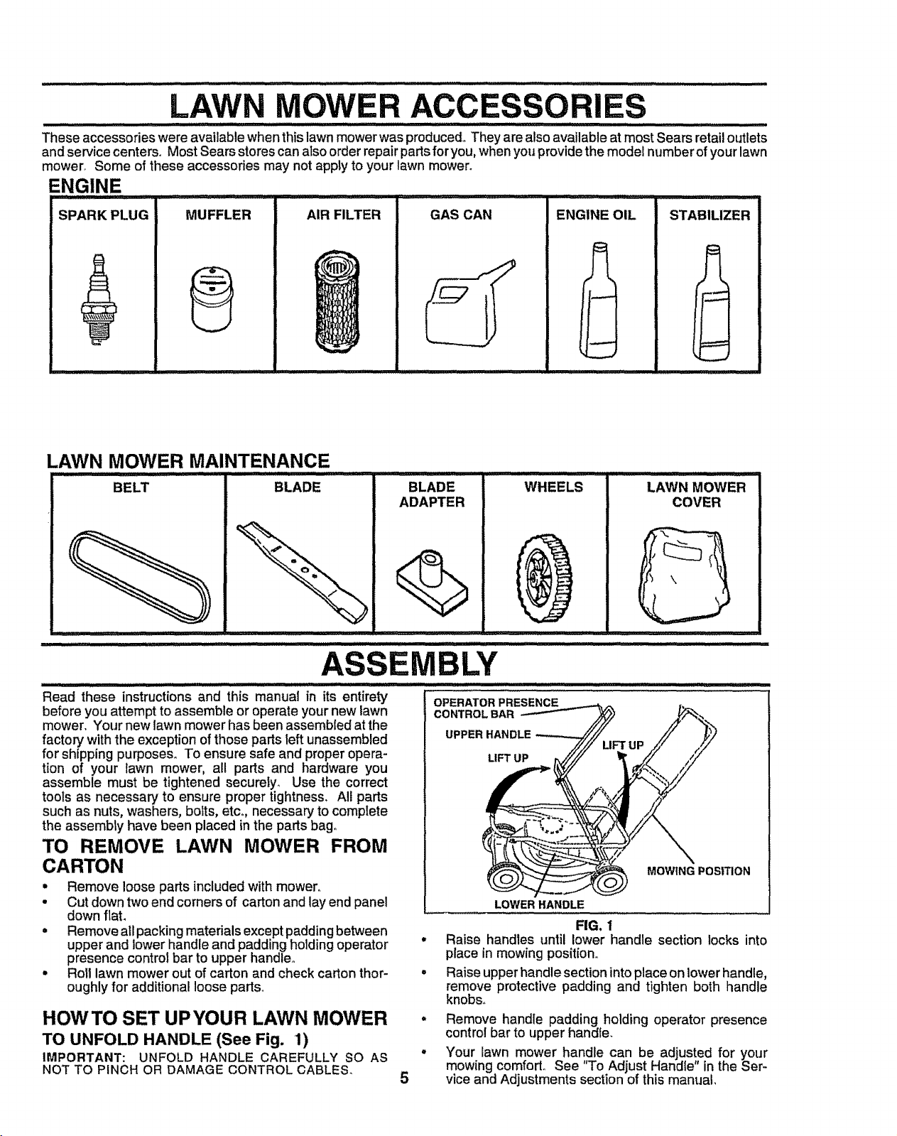
LAWN MOWER ACCESSORIES
tltltl I/ ttltlt t Itltt't' t II'lltltlt'll'll'ttt'ttttt tilt tilt I tlJH I I I I It!! ...........
These accessories were available when this lawn mower was produced° They are also available at most Sears retail outlets
and service centers. Most Sears stores can also order repair parts for you, when you providethe model number of your lawn
mower° Some of these accessories may not apply to your lawn mower.
ENGINE
SPARK PLUG MUFFLER
AIR FILTER GAS CAN
ENGINE OIL STABILIZER
LAWN MOWER MAINTENANCE
iii
BELT BLADE BLADE
ADAPTER
WHEELS
:: i i i ii illl=,H,= i1 .......
Read these instructions and this manual in its entire_
before you attempt to assemble or operate your new lawn
mower. Your new lawn mower has been assembled at the
factory with the exception of those parts left unassembled
for shipping purposes, To ensure safe and proper opera-
tion of your lawn mower, all parts and hardware you
assemble must be tightened securely_ Use the correct
tools as necessary to ensure proper tightness, All parts
such as nuts, washers, bolts, etc. necessary to complete
the assembly have been placed in the parts bag,,
TO REMOVE LAWN MOWER FROM
CARTON
• Remove loose parts included with mower,,
• Cut down two end corners of carton and lay end panel
down flat,
= Remove all packing materials except padding between
upper and lower handle and padding holding operator
presence control bar to upper handle,,
• Roll lawn mower out of carton and check carton thor-
oughly for additional loose parts,,
LAWN MOWER
COVER
MOWING POSITION
LOWER HANDLE
FIG. 1
Raise handles until lower handle section locks into
place in mowing position_
Raise upper handle section into place on lowerhandle,
remove protective padding and tighten both handle
knobs.
Remove handle padding holding operator presence
control bar to upper handle.
Your lawn mower handle can be adjusted for your
mowing comfort° See "To Adjust Handle" in the Ser-
vice and Adjustments section of this manual,
HOWTO SET UPYOUR LAWN MOWER .
TO UNFOLD HANDLE (See Fig. 1)
IMPORTANT: UNFOLD HANDLE CAREFULLY SO AS °
NOT TO PINCH OR DAMAGE CONTROL CABLES. 5
ASSEMBLY
OPERATOR PRESENCE
CONTROL BAR
UPPER HANDLE
LIFT UP
.................. ' i , illlll i i illlll i ,ll,, ill i i , illl ,i .... i ,,
O
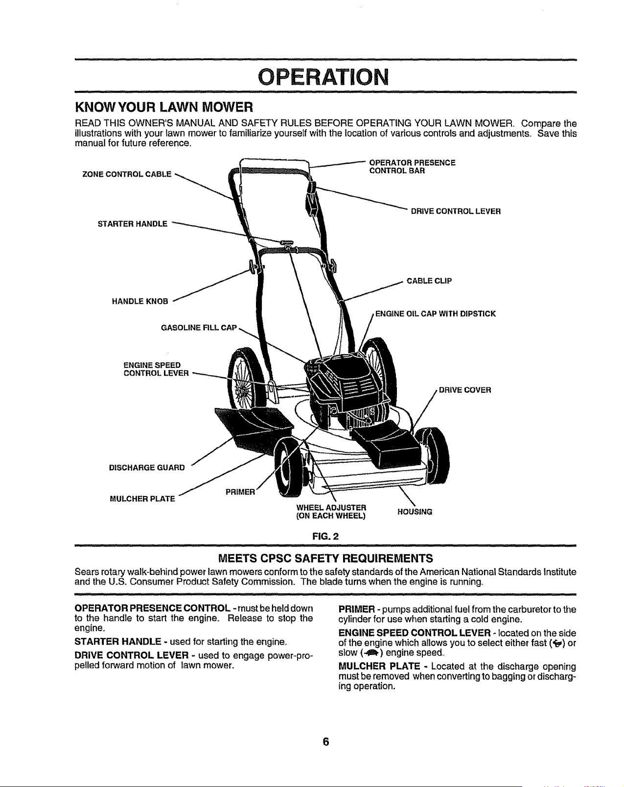
KNOW YOUR LAWN MOWER
READ THIS OWNER'S MANUAL AND SAFETY RULES BEFORE OPERATING YOUR LAWN MOWER, Compare the
illustrations with your lawn mower to familiarize yourself with the location of various controls and adjustments. Save this
manual for future reference,,
ZONECONTROLCABLE
OPERATOR PRESENCE
CONTROLBAR
STARTER HANDLE
DRIVE CONTROL LEVER
HANDLE KNOB
GASOLINE
CABLE CLIP
ENGINE OIL CAP WITH DIPSTICK
ENGINE SPEED
CONTROLLEVER
DISCHARGE GUARD
MULCHER PLATE
WHEELADJUSTER
(ON EACH WHEE_ HOUSING
FIG. 2
MEETS CPSC SAFE'P,/REQUIREMENTS
Sears rotary walk-behind power lawn mowers conform to the safety standards of the American National Standards Institute
and the U.SoConsumer Product Safety Commission° The blade turns when the engine is running°
OPERATOR PRESENCE CONTROL - must be held down
to the handle to start the engine. Release to stop the
engine.
STARTER HANDLE - used for starting the engine°
DRIVE CONTROL LEVER - used to engage power-pro-
pelled forward motion of lawn mower.
PRIMER - pumps additional fuel from the carburetorto the
cylinder for use when starting a cold engine.
ENGINE SPEED CONTROL LEVER - located onthe side
of the engine which allows you to select either fast (_) or
slow (-,Oh) engine speed
MULCHER PLATE _ Located at the discharge opening
must be removed when convertingto bagging ordischarg-
ing operation.
6
OPERATIC
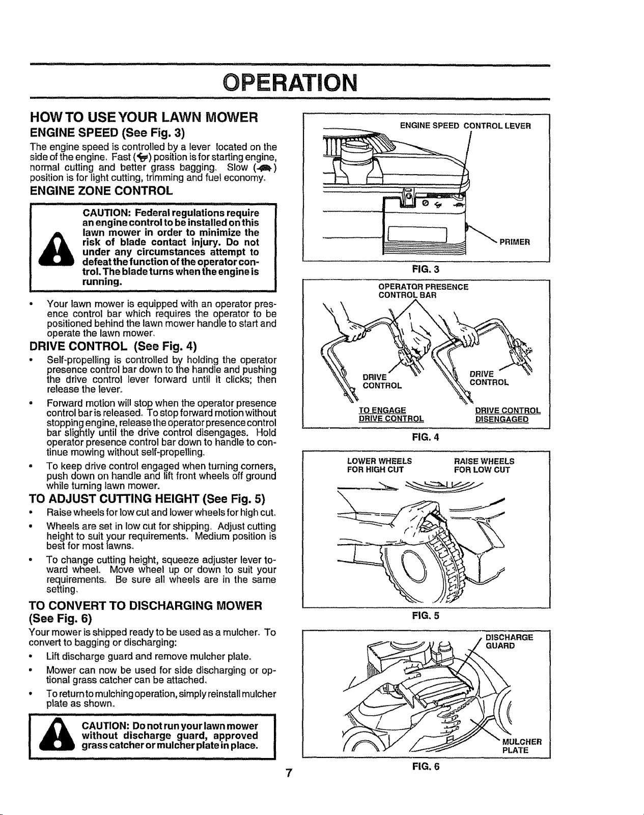
HOW TO USE YOUR LAWN MOWER
ENGINE SPEED (See Fig. 3)
The engine speed is controlled by a lever located on the
side of the engine, Fast (_) position isfor starting engine,
normal cutting and better grass bagging_ Slow (_)
position is for light cutting, trimming and fuel economy.
ENGINE ZONE CONTROL
CAUTION: Federal regulations require
an engine control to be installed on this
lawn mower in order to minimize the
risk of blade contact injury. Do not
under any circumstances attempt to
defeat the function of the operator con-
trol. The blade turns when the engine is
running.
. Your lawn mower is equipped with an operator pres-
ence control bar which requires the operator to be
positioned behind the lawn mower handle to start and
operate the lawn mower°
DRIVE CONTROL (See Fig. 4)
. Self-propelling is controlled by holding the operator
presence control bar down to the handle and pushing
the drive control lever forward until it clicks; then
release the lever,
o Forward motion will stop when the operator presence
control bar is released° To stop forward motion without
stopping engine, release the operator presence control
bar slightly until the drive control disengages. Hold
operator presence control bar down to handle to con-
tinue mowing without self-propelling
= To keep drive control engaged when turning corners,
push down on handle and lift front wheels off ground
while turning lawn mower.
TO ADJUST CUTTING HEIGHT (See Fig. 5)
° Raise wheels for low cut and lower wheels for high cut°
° Wheels are set in low cut for shipping, Adjust cutting
height to suit your requirements° Medium position is
best for most _awns,
To change cutting height, squeeze adjuster lever to-
ward wheel. Move wheel up or down to suit your
requirements, Be sure all wheels are in the same
setting_
TO CONVERT TO DISCHARGING MOWER
(See Fig. 6)
Your mower isshipped readyto be used as a mulcher° To
convert to bagging or discharging:
. Lift discharge guard and remove mulcher platen
, Mower can now be used for side discharging or op-
tional grass catcher can be attached_
° To returntomulching operation,simply reinstallmulcher
plate as shown°
-= ......... : Hi, i i
CAUTION: Do not run your lawn mower
without discharge guard, approved
grass catcher or mulcher plate in place.
ENGINE SPEED CONTROL LEVER
FIG. 3
OPERATOR PRESENCE
CONTROLBAR
DRIVE
CONTROL
CONTROL
,pRIV_ CONTR,Q_.
FIG. 4
DRIVE CONTBOL
DISENGAGED
LOWER WHEELS
FOR HIGH CUT
RAISE WHEELS
FOR LOW CUT
FIG. 5
/DISCHARGE
u_DLcHER
PLATE
7 FIG. 6
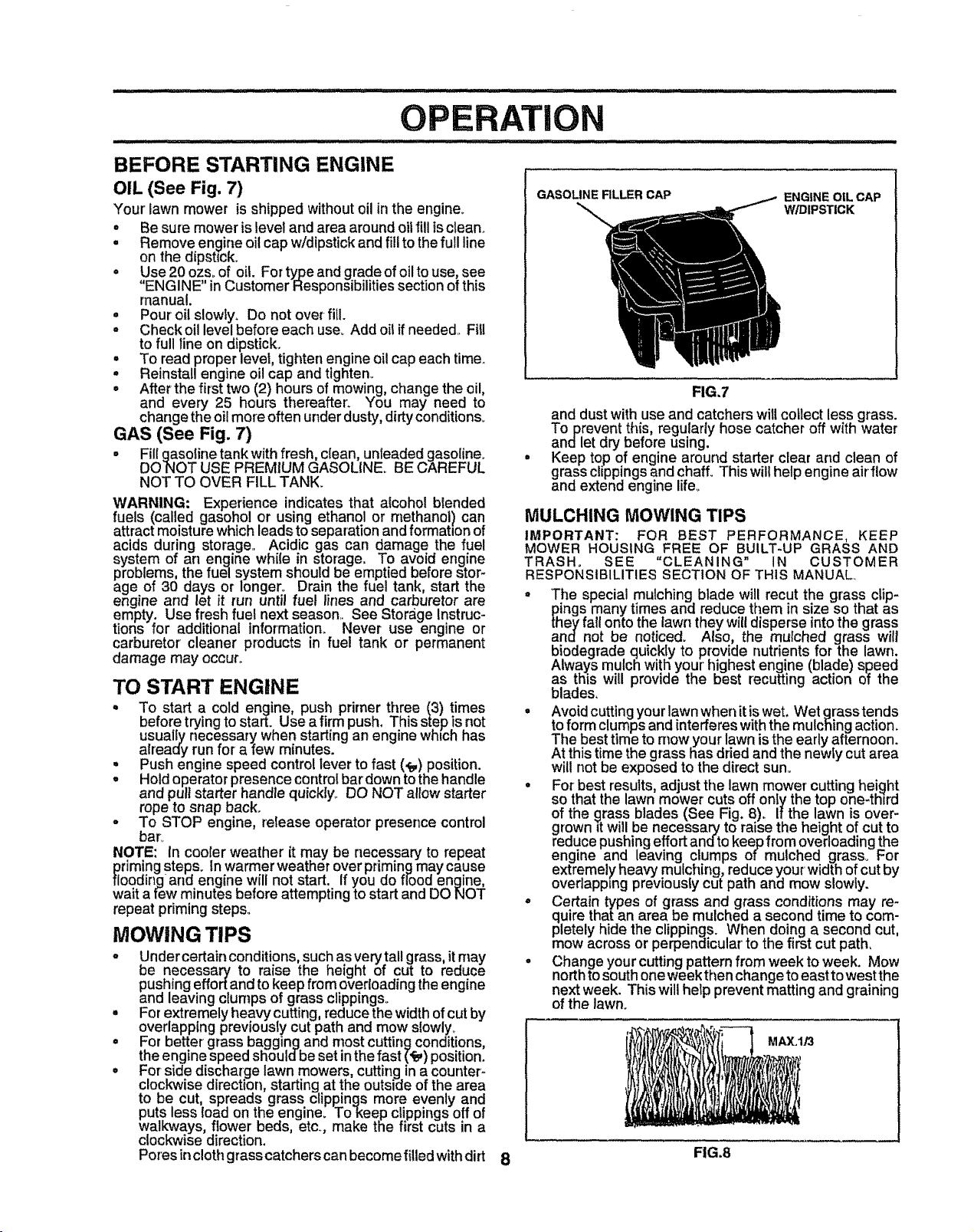
BEFORE STARTING ENGINE
OIL (See Fig. 7)
Your lawn mower is shipped withoutoil in the engine.
• Be sure mower is level and area around oil fill is clean.
o Remove engine oil cap w/dipstick and fill to the full line
on the dipstick.
• Use 20 ozsoof oil. For type and grade of oil to use, see
"ENGIN E" in Customer Responsibilities section of this
manual.
• Pour oil slowly_ Do not over-fill.
° Check oil level before each use° Add oil if needed., Fill
to full line on dipstick.
° To read proper level, tighten engine oil cap each time.
o Reinstall engine oil cap and tighten..
• After the first two (2) hours of mowing, change the oil,
and every 25 hours thereafter_ You may need to
change the oil more often under dusty, dirty conditions.
GAS (See Fig. 7)
• Fill gasoline tank with fresh, clean, unleaded gasoline_
DONOT USE PREMIUM GASOLINE_ BE CAREFUL
NOT TO OVER FILL TANK.
WARNING: Experience indicates that alcohol blended
fuels (called gasohol or using ethanol or methanol) can
attract moisture which leads to separation and formation of
acids during storage., Acidic gas can damage the fuel
system of an engine while in storage. To avoid engine
problems, the fuel system should be emptied before stor-
age of 30 days or longer° Drain the fuel tank, start the
engine and let it run until fuel lines and carburetor are
empty. Use fresh fuel next season, See Storage Instruc-
tions for additional information. Never use engine or
carburetor' cleaner products in fuel tank or permanent
damage may occur_
TO START ENGINE
• To start a cold engine, push primer three (3) times
before trying to start. Use a firm push. This step is not
usuallynecessary when starting an engine whtch has
already run for a few minutes.
° Push engine speed control lever to fast (_) position.
. Holdoperator presence controlbar down tothe handle
and pull starter handle quickly,, DO NOT allow starter
rope to snap back.
o To STOP engine, re_easeoperator presence control
bar°
NOTE: In cooler weather it may be necessary to repeat
priming steps. In warmer weather over primingmay cause
flooding and engine will not start. If you do flood engine,
wait a few minutes before attempting to start and DO NOT
repeat priming steps..
MOWING TIPS
- Under certain conditions, such as very tal! grass, it may
be necessary to raise the height of cut to reduce
pushing effort and to keep from overloadingthe engine
and leaving clumps of grass clippings°
° For extremely heavy cutting, reduce the width of cut by
overlapping previously cut path and mow slowly_
° For better grass bagging and most cutting conditions,
the engine speed shouldbe set in the fast (_) position.
• For side discharge lawn mowers, cutting in a counter-
clockwise direction, starting at the outside of the area
to be cut, spreads grass clippings more evenly and
puts less toad on the engine. To_eep cUppings off of
walkways, flower beds, etc., make the first cuts in a
clockwise direction.
Pores incloth grass catchers can become filled with dirt
GASOLINE RLLER CAP
ENGINE OIL CAP
W/DIPSTICK
FIG.7
and dustwith use and catcherswill collect less grass.
Toprevent this, regularly hose catcher off with water
andlet dry before using.
Keep top of engine around starter clear and clean of
grass clippingsand chaff_This will help engine airflow
and extend engine life_
MULCHING MOWING TIPS
IMPORTANT: FOR BEST PERFORMANCE, KEEP
MOWER HOUSING FREE OF BUILT-UP GRASS AND
TRASH. SEE "CLEANING" IN CUSTOMER
RESPONSIBILITIES SECTION OF THIS MANUAL°
= The special mulching blade will recut the grass clip-
pings many times and reduce them in size so that as
they fall onto the lawn they will disperse into the grass
and not be noticed. Also, the mutched grass will
biodegrade quickly to provide nutrients for the lawn.
Always mulch with your' highest engine (blade) speed
as this will provide the best recutting action of the
blades.
° Avoid cutting your lawn when it iswet. Wet grasstends
to form clumps and interferes with the mulching action.
The best time to mow your lawn isthe early afternoon.
At this time the grass has dried and the newly cut area
will not be exposed to the direct sum
• Forbest results, adjust the lawn mower cutting height
so that the lawn mower cuts off onfy the top one-third
of the grass blades (See Fig. 8)_ If the lawn is over-
grown tt will be necessary to raise the height of cut to
reduce pushing effort andto keep from overloading the
engine and leaving clumps of mulched grass. For
extremely heavy mulching, reduce your width of cut by
overlapping previously cut path an_ mow slowly.
- Certain types of grass and glass conditions may re-
quire tha_ an area be mulched a second time to com-
pletely hide the clippings. When doing a second cut,
mow across or perpendicular' to the first cut path,
• Change your cutting pattern from week to week. Mow
north to south one week then change to east to west the
next week. This will help prevent matting and graining
of the lawn.
MAX, l/3
8 FIG.8
i, ii
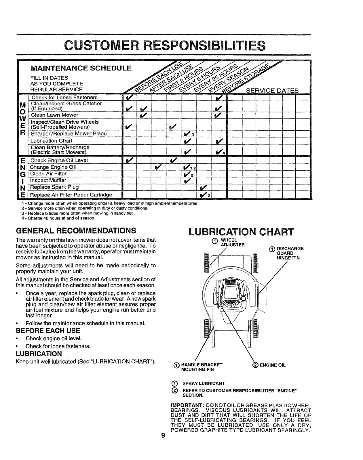
CUSTOM iLITIES
.................... i , 'MI..... _.............................
v'
_) Clean/inspect Grass Catcher
(If Equipped)
Clean Lawn Mower .............
EW Inspe'ct!€iean DriveWheels ..............
(Self-Propelled Mowers)
a sha.ipe_Repiace MowerBlade
Lubrication Chart
1/
: ; : vF3 " ,
v'
Clean Battery/Recharge
.(E..!ectric..Start...Mowers) I_
E Check Engine Oil Level ...... V P......... !/'
N Chang e Engine Oil ......... If _!,2
G clean Air F!lte[ ........... lt/2
| Inspect Muffler tt/ i
N Rep!acesp,arkPlug , _'
E Replace Air Filter Paper Cartridge t lt/2
1 - Change more often when operating under a heaw;t load or in high amblent temperatures
2 - Service more often when operating in ditty or dusty conditions°
3 - Replace blades more often when mowing in sandy selt.
4 - Charge 48 hours at end of season,
GENERAL RECOMMENDATIONS
The warranty on this lawn mower does not cover items that
have been subjected to operator abuse or negligenceo To
receive full value from the warranty, operator must maintain
mower as instructed in this manual°
Some adjustments will need to be made periodically to
properly maintain your unit°
All adjustments in the Service and Adjustments section of
this manual should be checked at least once each season.
• Once a year, replace the spark plug, clean or replace
air filter element and check blade forwearo Anewspark
plug and clean/new air filter element assures proper
air-fuel mixture and helps your engine run better and
last longer°
• Follow the maintenance schedule in this manual..
BEFORE EACH USE
• Check engine oil level.
• Check for ioose fasteners.
LUBRICATION
Keep unit welt lubricated (See "LUBRICATION CHART")°
LUBRICATION CHART
(_) WHEEL
ADJUSTER
(_ DISCHARGE
GUARD
HINGE PIN
(_ HANDLE BRACKET
MOUNTING PIN
ENGINE OIL
9
(_ SPRAY LUBRICANT
(_) REFER TO CUSTOMER RESPONSIBILITIES "ENGINE"
SECTIONo
IMPORTANT: DO NOT OILOR GREASE PLASTICWHEEL
BEARINGS.. VISCOUS LUBRICANTS WILL ATTRACT
DUST AND DIRT THAT WILL SHORTEN THE LIFE OF
THE SELF-LUBRICATING BEARINGS. IF YOU FEEL
THEY MUST BE LUBRICATED, USE ONLY A DRY,
POWERED GRAPHITE TYPE LUBRICANT SPARINGLY.
GUSTO ILITIES
LAW"MOWER ......... ........................................
Always observe safety rules when performing any mainte-
nanceo
TIRES
• Keep tires free of gasoline, oil,or insect controlchemi-
cals which can harm rubber_
• Avoid stumps, stones, deep ruts, sharp objects and
other hazards that may cause tire damage..
BLADE CARE
For best results, mower bfade must be kept sharp.
Replace bent or damaged blades.
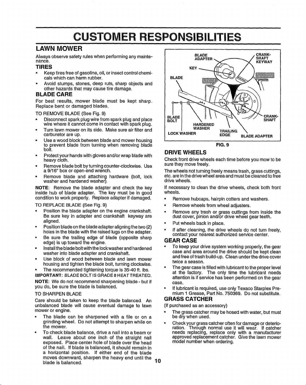
TO REMOVE BLADE (See Fig. 9)
= Disconnect spark plug wire from spark plug and place
wire where it cannot come in contact with spark plug.
= Turn lawn mower on its side_ Make sure air filter and
carburetor are up,
° Use a wood block between blade and mower housing
to prevent blade from turning when removing blade
bolt.
° Protect your hands with gloves and/or wrap blade with
heavy cloth,.
= Remove blade bolt byturning counter-clockwise., Use
a 9/16" box or open-end wrench.
o Remove blade and attaching hardware (bolt, lock
washer and hardened washer).•
NOTE: Remove the blade adapter and check the key
inside hub of blade adapter'. The key must be in good
condition to work properly.. Replace adapter if damaged°
TO REPLACE BLADE (See Fig. 9)
° Position the blade adapter on the engine crankshaft.
Be sure key in adapter and crankshaft keyway are
aiigned.
o Position blade on the blade adapter aligning the two (2)
holes in the blade with the raised lugs on the adapter°
• Be sure the trailing edge of blade (opposite sharp
edge) is up toward the engine..
° Instaltthe blade bolt withthe lockwasher and hardened
washer into blade adapter and crankshaft.
• Use block of wood between blade and lawn mower
housing and tighten the blade bolt, turning clockwise.
• The recommended tightening torque is 35-40 ft. lbs.,
IMPORTANT: BLADE BOLT IS GRADE 8 HEATTREATED.
NOTE: We do not recommend sharpening blade - but if
you do, be sure the blade is balanced.
TO SHARPEN BLADE
Care should be taken to keep the blade balanced_ An
unbalanced blade will cause eventual damage to lawn
mower or engine_
• The blade can be sharpened with a file or on a
grinding wheel. Do not attempt to sharpen while on
the mower.
° To check blade balance, drive a nail into a beam or
wall. Leave about one inch of the straight nail
exposed. Place center hole of blade over the head
of the nail. If blade is balanced, it should remain in
a horizontal position° If either end of the blade
moves downward, sharpen the heavy end until the
blade is balanced.,
10
BLADE CRANK-
ADAPTER SHAFT
KEYWAY
KEY
BLADE
HARDENED
WASHER
TRAlUNG
LOCK WASHER EDGE
SHAFT
° Remove hubcaps, hairpin cotters and washers.
• Remove wheels from wheel adjusters..
• Remove any trash or grass cuttings from inside the
dust cover, pinion and/or drive wheel gear teeth.
• Put wheels back in place.
° If after cleaning, the drive wheels do not turn freely,
contact your nearest authorized service center.
GEAR CASE
- To keep your drive system working properly, the gear
case and area around the drive should be kept clean
and free of trash build-up. Clean under the drivecover
twice a season.
° The gear case isfilled with lubricant to the proper level
at the factory° The only time the lubricant needs
attention is if service has been performed on the gear
case.
• if lubricant is required, use only Texaco Starplex Pre-
mium 1 Grease, Part No. 750369. Do not substitute.
GRASS CATCHER
(If purchased as an accessory)
• The grass catcher may be hosed with water, but must
be dry when used..
Q Check your grass catcher oftenfor damage or deterio-
ration., Through normal use it will wear° If catcher'
needs replacing, replace only with a manufacturer
approved replacement catcher. Give the lawn mower
model number when ordering°
FIG. 9
DRIVE WHEELS
Check front drive wheels each time before you mow to be
sure they move freely.,
The wheels not turning freely means trash, grass cuttings,
etc. are in the drive wheel area and must be cleaned to free
drive wheels.
If necessary to clean the drive wheels, check both front
wheels.
BLADE ADAPTER
CU
NSIBiLiTiES
ENGINE
LUBRICATION
Use only high quality detergent oil rated with API service
classification SF or SG., Select the oil's SAEviscosity grade
according to your expected operating temperature.,
SAEviscos,_G_DES
"l_i'lt_tl
_F -20" 0" 30_ 32" 40 _ {_* 80" t0_ _
_C -30* -20 ° -I0 _ O' t0" 20" 3(} _ 40"
TEMPERATURE RANGE ANTiCiPATED BEFORE NEXT OIL CHANGE
NOTE: Although multi-viscosity oils (5W30, 10W30 etc,)
improve starting in cold weather, these multi-viscosity oils
will result in increased oil consumption when used above
32°F. Check your engine oil level more frequently to avoid
ossible engine damage from running low on oil,,
hange the oil after the first two hours of operation and
every 25 hours thereafter or at least once a year if the lawn
mower is not used for 25 hours in one year°
Check the crankcase oil leve! before starting the engine
and after each five (5) hours of continuous use, Add SAE
30 motor oi! or equivalent. Tighten oil plug securely each
time you check the oil level
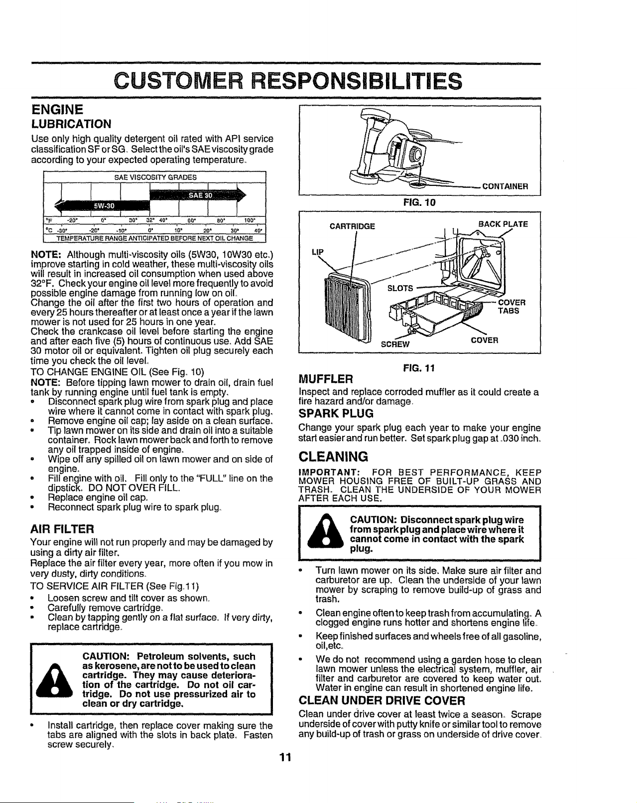
TO CHANGE ENGINE OIL (See Fig,, 10)
NOTE: Before tipping lawn mower to drain oil, drain fuel
tank by running engine until fuel tank is empty.
. Disconnect spark plug wire from spark plug and place
wire where it cannot come in contact with spark plug.
. Remove engine oil cap; lay aside on a clean surface°
. Tip lawn mower on its side and drain oil intoa suitable
container. Rock lawn mower back and forth to remove
any oil trapped inside of engine.
• Wipe off any spilled oil on lawn mower and on side of
engine.
o Fill engine with oil. Fill only to the "FULL" line on the
dipstick° DO NOT OVER FILL,
° Replace engine oil cap°
° Reconnect spark plug wire to spark plug_
AIR FILTER
Your engine will not run properly and may be damaged by
using a dirty air filter.
Replace the air filter every year, more often if you mow in
very dusty, dirty conditions°
TO SERVICE AIR FILTER (See Fig] 1)
° Loosen screw and tilt cover as shown,
° Carefully remove cartridge,,
• Clean by tapping gently on a flat surfacer If very dirty,
replace cartddge.,
°
CAUTION: Petroleum solvents, such
as kerosene, are not to be used to clean
cartridge. They may cause deteriora-
tion of the cartridge. Do not oil car-
tridge. Do not use pressurized air to
clean or dry cartridge.
Install cartridge, then replace cover making sure the
tabs are aligned with the slots in back plate. Fasten
screw securely.
FIG. 10
CARTRIDGE BACK PLATE
LIP
\
TABS
SCREW
COVER
FIG. 11
MUFFLER
Inspect and replace corroded muffler as it could create a
fire hazard and/or damage,
SPARK PLUG
Change your spark plug each year to make your engine
start easier and run better. Set spark plug gap at .,030inch.
CLEANING
IMPORTANT: FOR BEST PERFORMANCE, KEEP
MOWER HOUSING FREE OF BUILT-UP GRASS AND
TRASH. CLEAN THE UNDERSIDE OF YOUR MOWER
AFTER EACH USE.
_ CAUTION: Disconnect spark plug wire
from spark plug and place wire where it
cannot come in contact with the spark
plug.
° Turn lawn mower on its side, Make sure air filter and
carburetor are up. Clean the underside of your tawn
mower by scraping to remove build-up of grass and
trash.
° Clean engine oftento keep trash from accumulatingo A
clogged engine runs hotter and shortens engine life,,
• Keep finished surfaces and wheels free of all gasoline,
oil,etc,,
- We do not recommend using a garden hose to clean
lawn mower unless the electrical system, muffler, air
filter and carburetor are covered to keep water out.
Water in engine can result in shortened engine lifeo
CLEAN UNDER DRIVE COVER
Clean under ddve cover at least twice a season° Scrape
underside of cover with putty knife or similar tool to remove
any build-up of trash or grass on underside of drive cover,
11
AND ADJUST
CAUTION: BEFORE PERFORMING ANY SERVICE OR ADJUSTMENTS:
Release control bar.
Make sure the blade and all moving parts have completely stopped.
o
Disconnect spark plug wire from spark plug and place where it cannot come in contact with plug.
LAWN MOWER
TO ADJUST CUTTING HEIGHT
See "TO ADJUST CUTTING HEIGHT" in the Operation
section of this manual.
DISCHARGE GUARD
The discharge guard, attached to the dischargeopening of
your lawn mower, is providedto prevent the possibilityof
injury resulting from objects being thrown out of the dis-
charge opening into the operator mowing position, if the
dischargeguard becomes damaged, it shouldbe replaced_
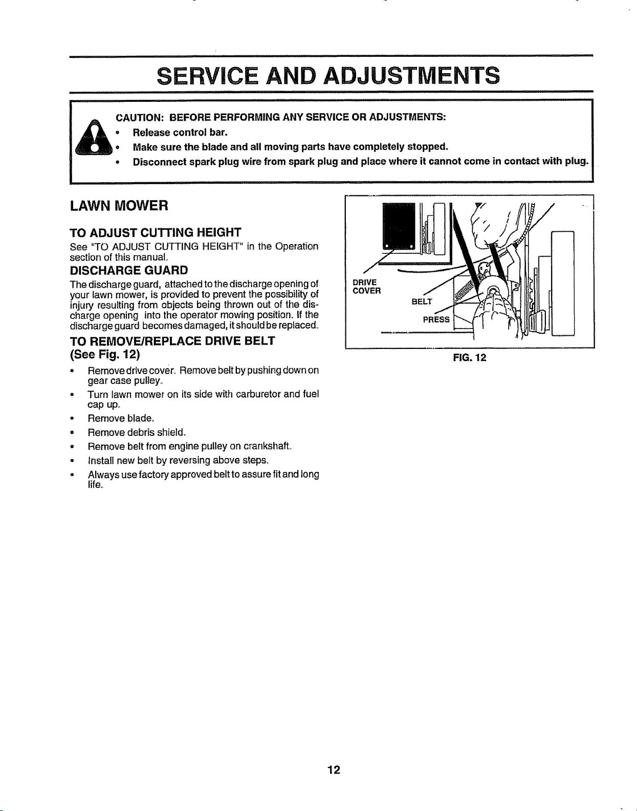
TO REMOVE/REPLACE DRIVE BELT
(See Fig. 12)
o Remove drive cover_ Remove belt by pushing down on
gear' case puUey,_
• Turn lawn mower on its side with carburetor and fuel
cap upo
= Remove blade.
° Remove debris shield.
o Remove belt from engine pulley on crankshaft°
° lnstaU new belt by reversing above steps,
° Always use factory approved belt to assure fit and long
life.
DRIVE
COVER
BELT
PRESS N
LP
FIG. 12
12
AND ADJUSTMENTS
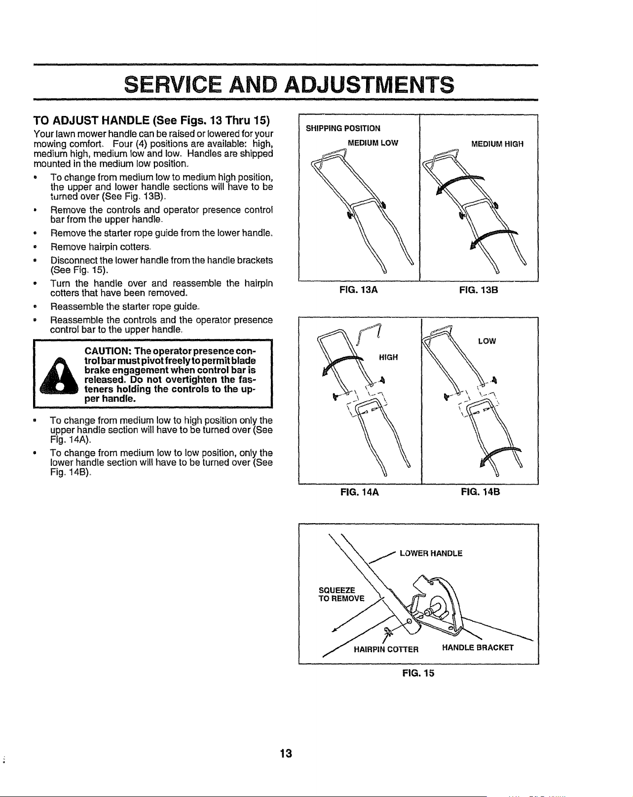
TO ADJUST HANDLE (See Figs. 13 Thru 15)
Your lawn mower handle can be raised or lowered for your
mowing comforL Four (4) positions are available: high,
medium high, medium tow and low. Handles are shipped
mounted in the medium low position.
• To change from medium low to medium high position,
the upper and lower handle sections will have to be
turned over (See Fig. t3B)o
• Remove the controls and operator presence control
bar from the upper handle.
o Remove the starter rope guide from the lower handle,
. Remove hairpin cotters_
= Disconnect the lower handle from the handle brackets
(See Fig_ 15).
• Turn the handle over and reassemble the hairpin
cotters that have been removed.
• Reassemble the starter rope guide
° Reassemble the controls and the operator presence
control bar to the upper handle,
CAUTION: The operator presence con-
_ trol bar must pivot freely to permit blade
brake engagement when control bar is
released° Do not overtighten the fas-
teners holding the controls to the up-
per handle.
• To change from medium low to high position only the
upper handle section will have to be turned over (See
Fig. I4A).
° To change from medium low to low position, only the
lower handle section will have to be turned over (See
Fig, 14B),
SHIPPING POSITION
MEDIUM LOW
MEDIUM HIGH
FIG. 13A FIG. 13B
LOW
FIG. 14A FIG. 14B
LOWER HANDLE
SQUEEZE
TO REMOVE
HAIRPIN COTTER HANDLE BRACKET
FIG. 15
13
ENGINE
ENGINE SPEED
Your engine speed has been factory seL Do not attempt to
increase engine speed or it may result in personal injury_ If
you believe that engine is running too fast or too slow, take
your mower to an authorized service center for repair and
adjustmenL
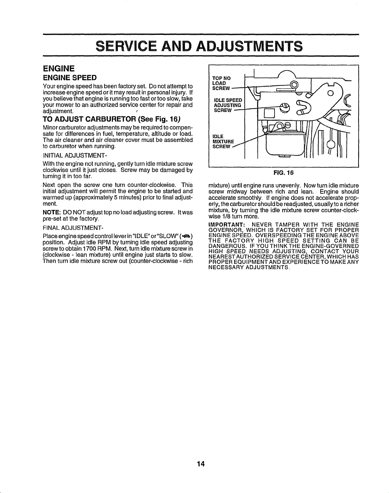
TO ADJUST CARBURETOR (See Fig. 16)
Minor carburetor adjustments may be required to compen-
sate for differences in fuel, temperature, altitude or load.
The air cleaner and air cleaner cover must be assembled
to carburetor when running.
INITIAL ADJUSTMENT-
With the engine not running, gently turn idle mixture screw
cleckwise until it just cioses_ Screw may be damaged by
turning it in too far_
Next open the screw one turn counter-clockwise. This
initial adjustment will pemlit the engine to be started and
warmed up (approximately 5 minutes) prior to final adjust-
ment.
NOTE: DO NOT adjust top no loadadjusting screw. It was
pre-set at the factory,
FINAL ADJUSTMENT-
Place engine speed control lever in "IDLE" or"SLOW" (-_!)
position. Adjust idle RPM by turning idle speed adjusting
screw to obtain 1700 RPM Next, tum idle mixture screw in
(clockwise - lean mixture) until engine just starts to slow_
Then turn idle mixture screw out (counter-clockwise - rich
TOP NO
LOAD
IDLE SPEED
ADJUSTING
SCREW
IDLE
MIXTURE
SCREW
FIG. 16
mixture) until engine runs unevenly. Now turn idle mixture
screw midway between rich and lean. Engine should
accelerate smoothly If engine does not accelerate prop-
erly, thecarburetorshould be readjusted, usuallyto a richer
mixture, by turning the idle mixture screw counter-clock-
wise 1/8 turn more.
IMPORTANT: NEVER TAMPER WITH THE ENGINE
GOVERNOR, WHICH IS FACTORY SET FOR PROPER
ENGINE SPEED. OVERSPEEDING THE ENGINE ABOVE
THE FACTORY HIGH SPEED SETTING CAN BE
DANGEROUS. IF YOU THINK THE ENGINE-GOVERNED
HIGH SPEED NEEDS ADJUSTING, CONTACT YOUR
NEAREST AUTHORIZED SERVICE CENTER, WHICH HAS
PROPER EQUIPMENT AND EXPERIENCE TO MAKE ANY
NECESSARY ADJUSTMENTS.
14
Immediately prepare your lawn mower for storage at the
end of the season or if the unit will not be used for 30 days
or more.
LAWN MOWER
When lawn mower isto be stored for a period of time, clean
it thoroughly, remove all dirt, grease, leaves, etc. Store in
a ciean, dry area.
. Clean entire lawn mower (See "CLEANING" in the
Customers Responsibilities section of this manua!).
= Lubricate as shown in the Customers Responsibilities
section of this manual.
o Be sure that all nuts, bolts, screws, and pins are
securely fastened. Inspect moving parts for damage,
breakage and wear° Replace if necessary°
. Touch up all rusted or chipped paint surfaces; sand
lightly before painting,.
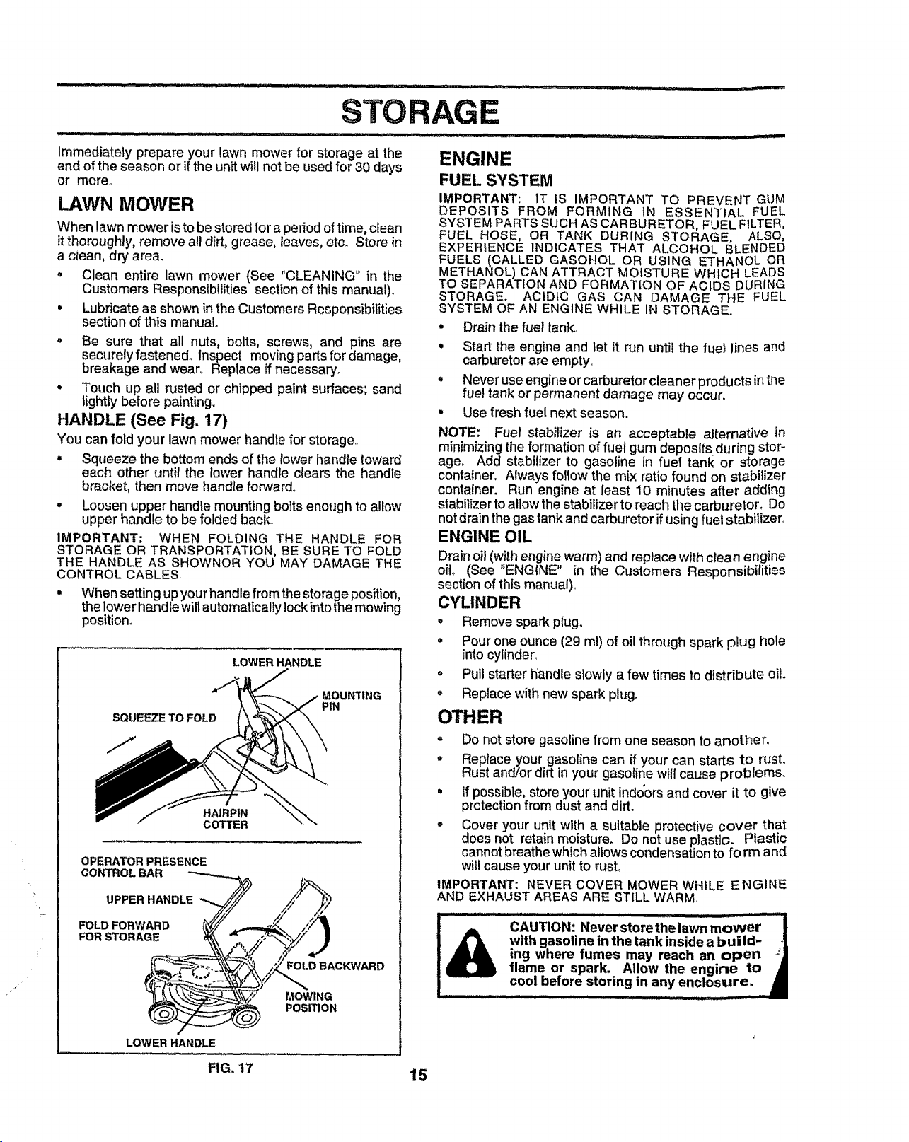
HANDLE (See Fig. 17)
You can fold your lawn mower handte for storage°
• Squeeze the bottom ends of the tower handle toward
each other until the lower handle clears the handle
bracket, then move handle forward_
= Loosen upper handle mounting bolts enough to allow
upper handle to be folded back.
IMPORTANT; WHEN FOLDING THE HANDLE FOR
STORAGE OR TRANSPORTATION, BE SURE TO FOLD
THE HANDLE AS SHOWNOR YOU MAY DAMAGE THE
CONTROL CABLES,
° When setting up your handle from the storage position,
the lower handle will automatically lock intothe mowing
position°
SQUEEZE TO FOLD
LOWER HANDLE
MOUN_NG
PIN
HAIRPIN
COTTER
OPERATOR PRESENCE
_ ot.oBAC WARO
?zxx
MOWING
POSITION
LOWER HANDLE
FIG, '17
ENGINE
FUEL SYSTEM
IMPORTANT: IT IS IMPORTANT TO PREVENT GUM
DEPOSITS FROM FORMING IN ESSENTIAL FUEL
SYSTEM PARTS SUCH AS CARBURETOR, FUEL FILTER,
FUEL HOSE, OR TANK DURING STORAGE, ALSO,
EXPERIENCE INDICATES THAT ALCOHOL BLENDED
FUELS (CALLED GASOHOL OR USING ETHANOL OR
METHANOL) CAN ATTRACT MOISTURE WHICH LEADS
TO SEPARATION AND FORMATION OF ACIDS DURING
STORAGE. ACIDIC GAS CAN DAMAGE THE FUEL
SYSTEM OF AN ENGINE WHILE IN STORAGE_
o Drain the fuel tank,.
o Start the engine and tel it run until the fuei lines and
carburetor are empty,.
• Never use engine or carburetor cleaner products in the
fuel tank or permanent damage may occur.
• Use fresh fuel next season,.
NOTE; Fuel stabilizer is an acceptable alternative in
minimizing the formation of fuel gum deposits during stor-
age. Add stabilizer to gasoline in fuel tank or storage
container° Always follow the mix ratio found on stabilizer
container. Run engine at least 10 minutes after adding
stabilizer to allowthe stabilizer to reach the carburetor. Do
not drain the gas tank and carburetor if using fuel stabilizer,.
ENGINE OIL
Drain oil (with engine warm) and replace with clean engine
oil (See "ENGINE" in the Customers Responsibilities
section of this manual)_
CYLINDER
• Remove spark plug.
° Pour one ounce (29 ml) of oil through spark plug hole
into cylinder_
° Pull starter handle slowly a few times to distribute oil.
= Replace with new spark plug.
OTHER
° Do not store gasoline from one season to another.
• Replace your gasoline can if your can starts to rust°
Rust and/or dirt inyour gasoline will cause problems,,
° If possible, store your unit indo_orsand cover it to give
protectionfrom dust and dirt.
. Cover your unit with a suitable protective cover that
does not retain moisture. Do not use plastic. Plastic
cannot breathe which allows condensation to fo rm and
wil! cause your unit to rusL
IMPORTANT: NEVER COVER MOWER WHILE ENGINE
AND EXHAUST AREAS ARE STILL WARM
_ _ ' , _ ............................. dj LIIIIII I I
CAUTION: Never store the lawn mower [
with gasoline in the tank inside a build- ,|
ing where fumes may reach an open ;]
flame or spark. Allow the engine to •
cool before storing in any enclosure. _1
............................ _ ii i,,,i
15
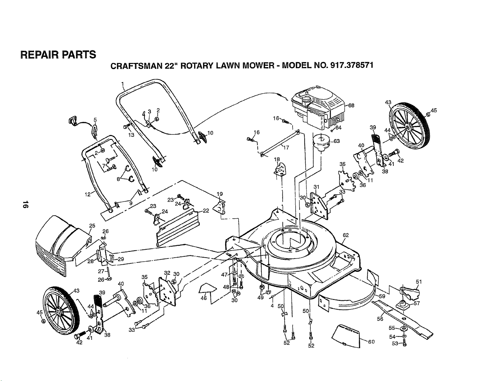
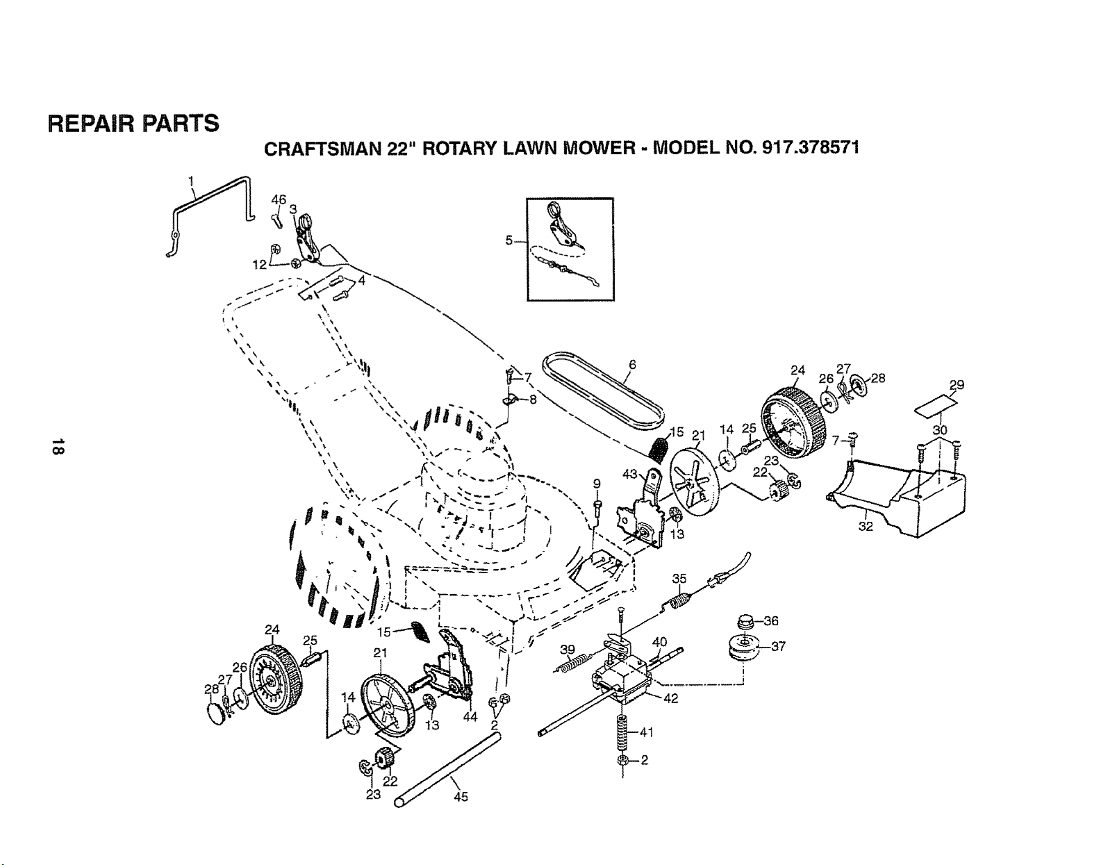
REPAIR PARTS
CRAFTSMAN 22" ROTARY LAWN MOWER - MODEL NO. 917.378571
o_
25
26
19
16
31
35
62
39
4o
36
42
45
26.-_
39
38
4O
4 5C
!
1
52
56
51
52 53-"_
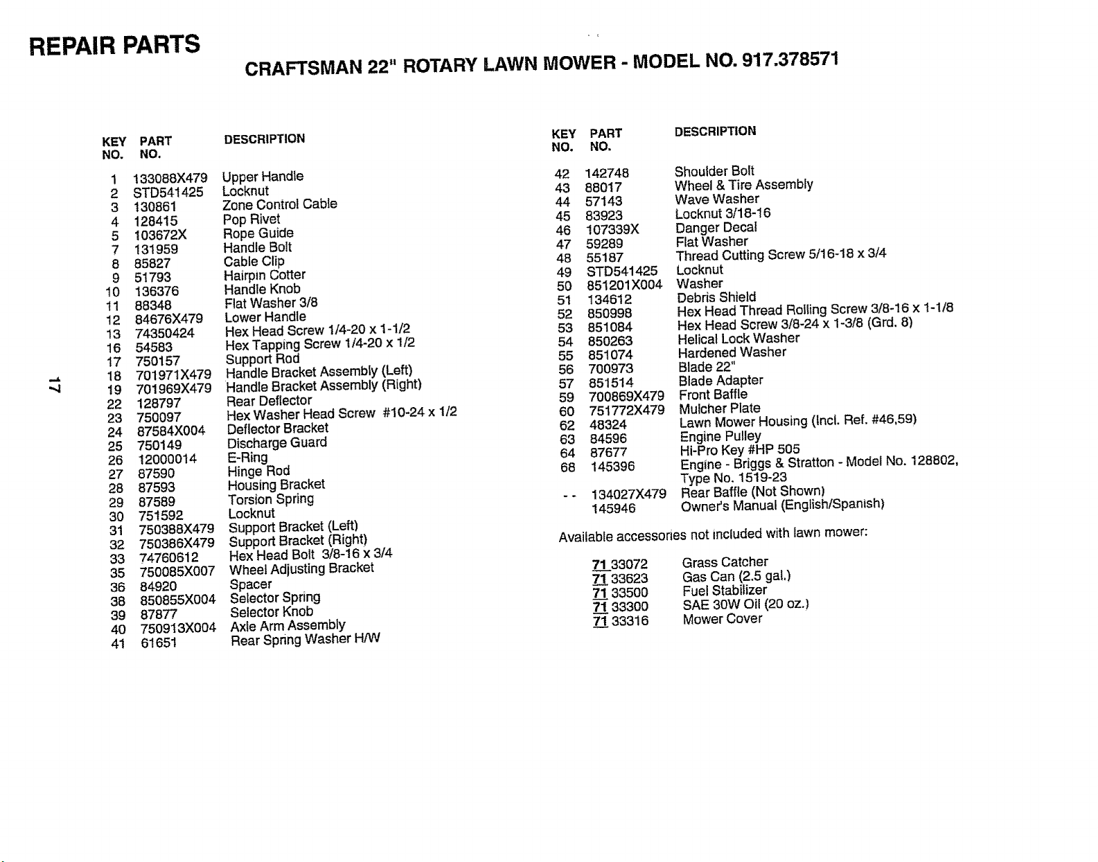
REPAIR PARTS
CRAFTSMAN 22" ROTARY LAWN MOWER - MODEL NO. 917.378571
.q
KEY PART
NO. NO.
1 133088X479
2 STD541425
3 130861
4 128415
5 103672X
7 131959
8 85827
9 51793
10 136376
tl 88348
12 84676X479
13 74350424
16 54583
17 750157
18 70t971X479
19 701969){479
22 128797
23 750097
24 87584X004
25 750149
26 12000014
27 87590
28 87593
29 87589
30 751592
31 750388X479
32 750386X479
33 74760612
35 750085X007
36 84920
38 850855X004
39 87877
40 750913X004
41 61651
DESCRIPTION KEY PART DESCRIPTION
NO. NO,
Upper Handle
Locknut
Zone Control Cable
Pop Rivet
Rope Guide
Handle Bolt
Cable Clip
Hairpin Cotter
Handle Knob
Flat Washer 3/8
Lower Handle
Hex Head Screw 1/4-20 x 1-I/2
Hex Tapping Screw 1/4-20 x 1/2
Support Rod
Handle Bracket Assembly (Left)
Handle Bracket Assembly (Right)
Rear Deflector
Hex Washer Head Screw #10-24 x 1/2
Deflector Bracket
Discharge Guard
E-Ring
Hinge Rod
Housing Bracket
Torsion Spring
Locknut
Support Bracket (Left)
Support Bracket (Right)
Hex Head Bolt 3/8-16 x 3/'4
Wheel Adjusting Bracket
Spacer
Selector Spring
Selector Knob
Axle Arm Assembly
Rear Spring Washer H/W
42 142748
43 88017
44 57143
45 83923
46 107339X
47 59289
48 55187
49 STD541425
50 851201X004
5t 134612
52 850998
53 851084
54 850263
55 851074
56 700973
57 851514
59 700869X479
60 751772X479
62 48324
63 84596
64 87677
68 145396
134027)(479
145946
Shoulder Bolt
Wheel & Tire Assembly
Wave Washer
Locknut 3/18-16
Danger Decal
Flat Washer
Thread Cutting Screw 5/16-18 x 3/4
Locknut
Washer
Debris Shield
Hex Head Thread Rolling Screw 3/8-16 x 1-1/8
Hex Head Screw 3/8-24 x 1-3/8 (Grd. 8)
Helical Lock Washer
Hardened Washer
Blade 22"
Blade Adapter
Front Baffle
Mulcher Plate
Lawn Mower Housing (incl. Ref. #46,59)
Engine Pulley
Hi-Pro Key #HP 505
Engine - Briggs & Stratton - Model No. 128802,
Type No. 1519-23
Rear Baffle (Not Shown)
Owner's Manual (English/Spanish)
Available accessones not included with lawn mower:
71__.33072 Grass Catcher
33623 Gas Can (2.5 gal.)
7_1133500 Fue! Stabilizer
7_!33300 SAE 30W Oil (20 oz.)
71 33316 Mower Cover
REPAIR PARTS
CRAFTSMAN 22" ROTARY LAWN MOWER - MODEL NO. 917.378571
Co
26
24 27
/26 .Z6_'v'28
i
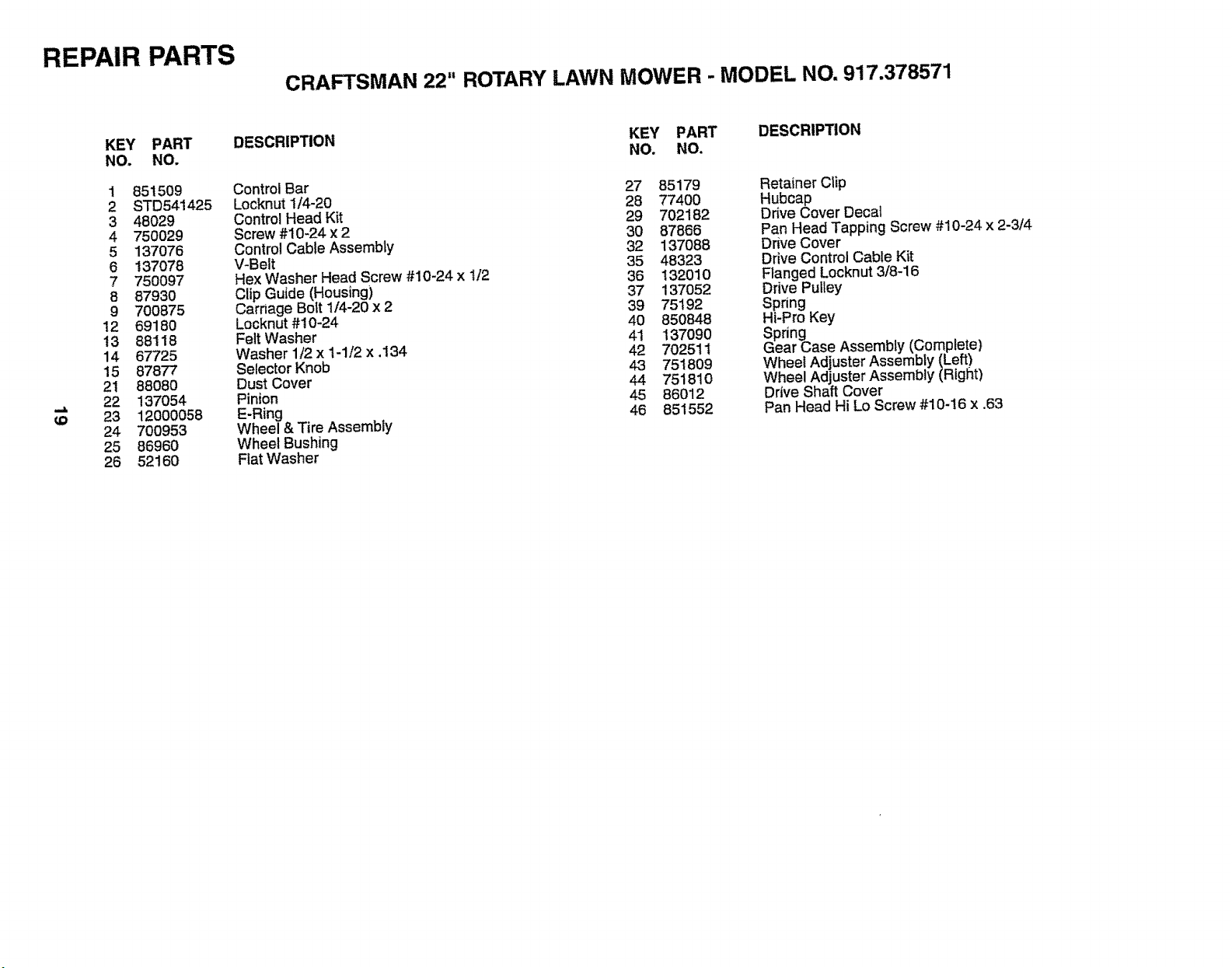
REPAIR PARTS
CRAFTSMAN 22" ROTARY LAWN MOWER - MODEL NO. 917.378571
_o
KEY PART
NO. NO.
1 851509
2 STD541425
3 48029
4 750O29
5 137076
6 137O78
7 750097
8 87930
9 700875
12 69180
13 88118
14 67725
15 87877
21 88080
22 137054
23 12000058
24 70O953
25 86960
26 52160
DESCRIPTION KEY PART DESCRIPTION
NO. NO.
Control Bar 27 85179
Locknut I/4-20 28 77400
Control Head Kit 29 702182
Screw #10-24 x 2 30 87866
Control Cable Assembly 32 137088
V-Belt 35 48323
Hex Washer Head Screw #10-24 x 1/2 36 132010
Clip Guide (Housing) 37 137052
Carnage Bolt 1/4-20 x 2 39 75192
Locknut #10-24 40 850848
Felt Washer 41 137090
Washer 1/2 x 1-1/2 x .134 42 702511
Selector Knob 43 751809
Dust Cover 44 751810
Pinion 45 86012
E-Ring 46 851552
Wheel & Tire Assembly
Wheel Bushing
Flat Washer
Retainer Clip
Hubcap
Drive Cover Decal
Pan Head Tapping Screw #10-24 x 2-3/4
Drive Cover
Drive Control Cable Kit
Flanged Locknut 3/8-16
Drive Pulley
Spring
Hi-Pro Key
Spring
Gear Case Assembly (Complete)
Wheel Adjuster Assembly (Left)
Wheel Adjuster Assembly (Right)
Drive Shaft Cover
Pan Head Hi Lo Screw #10-16 x .63
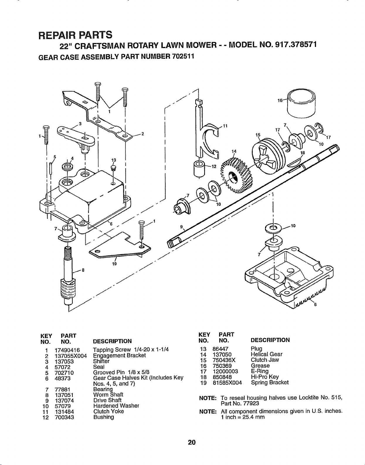
REPAIR PARTS
22" CRAFTSMAN ROTARY LAWN MOWER - - MODEL NO. 917.378571
GEAR CASE ASSEMBLY PART NUMBER 702511
19
15
17
I
I
lO
7
KEY
NO.
1
2
3
4
5
6
7
8
9
10
11
12
PART
NO.
17490416
137055X004
137053
57072
7O2710
48373
77881
137051
137O74
57079
131484
700343
DESCRIPTION
Tapping Screw 1/4-20 x 1-1/4
Engagement Bracket
Shifter
Seat
Grooved Pin 1/8 x 5/8
Gear Case Halves Kit (Includes Key
Nos. 4, 5, and 7)
earing
orm Shaft
Drive Shaft
Hardened Washer
Clutch Yoke
Bushing
KEY PART
NO, NO. DESCRIPTION
13 86447 Plug
14 137050 Helical Gear
15 750436X Clutch Jaw
16 750369 Grease
17 12000003 E-Ring
18 850848 Hi-Pro Key
19 81585X004 Spring Bracket
NOTE: To reseal housing halves use Locktite No_ 515,
Part Noo 77923
NOTE: All component dimensions given in U S. inches..
1 inch = 25.4 mm
20
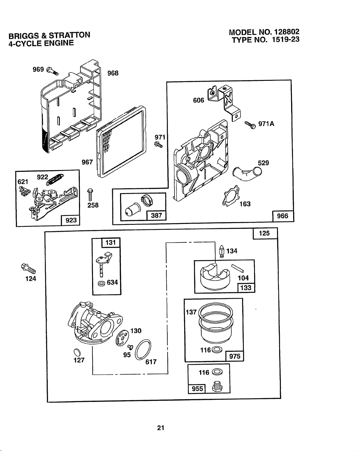
BRIGGS & STRATTON
4-CYCLE ENGINE
MODEL NO. 128802
TYPE NO. 1519-23
"J"
f
634
124
127
r
!
!
l
1
I
........ _......[,_
134
,H,
137
116 (_)
21
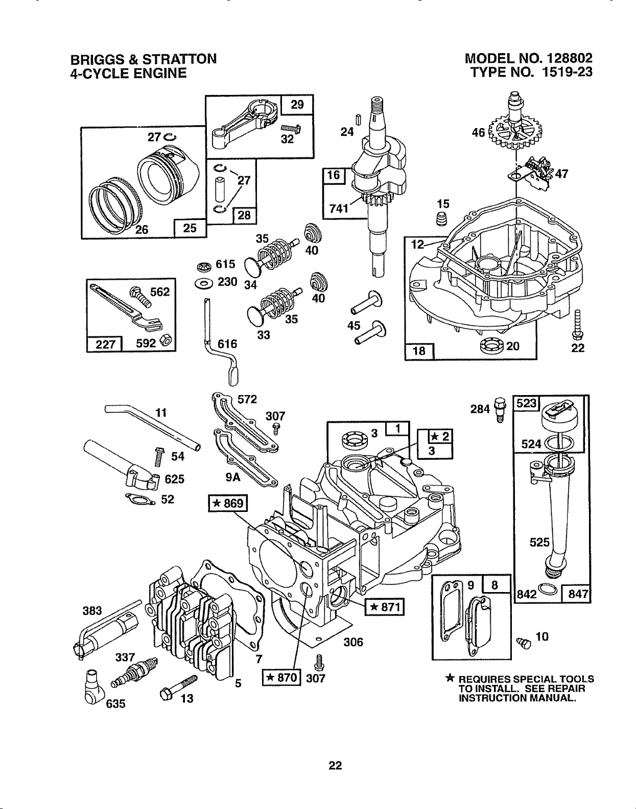
BRIGGS & STRATTON
4-CYCLE ENGINE
27O
_, 592
54
625
52
_615 _40
230 34
572
_-_ 307
24
3
306
15
@
MODEL NO. 128802
TYPE NO. 1519-23
1
20 22
a42__
"k REQUIRES SPECIAL TOOLS
TO INSTALL. SEE REPAIR
INSTRUCTION MANUAL,
22
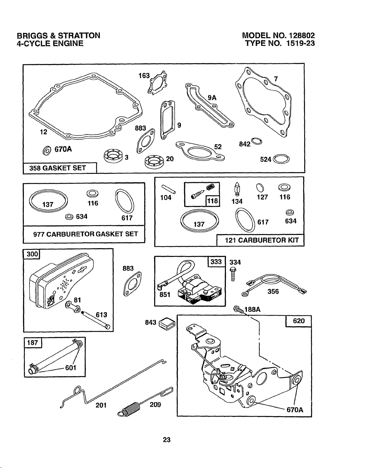
BRIGGS & STRATTON
4-CYCLE ENGINE
MODEL NO. 128802
TYPE NO. 1519-23
842 _
524 0
116
Q 634 617
977 CARBURETOR GASKET SET
"_J_" ............883
104
I__-__ ........ 134_]
127 116
0
617 634
I i21CAReU"ETORKI_
334
" -............... _188A
..... ,,, :..
23
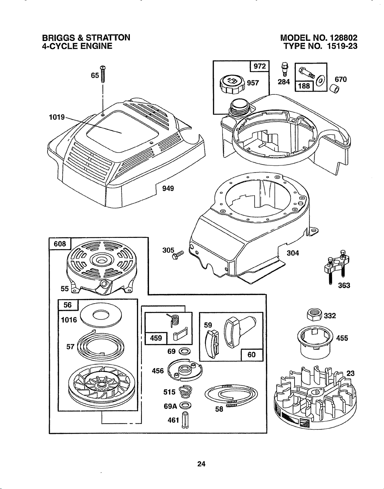
BRIGGS & STRATTON
4-CYCLE ENGINE
MODEL NO. 128802
TYPE NO, 1519-23
949
304
363
57
L
illl illl t
69
456
51s
69A
461
_332
455
23
24
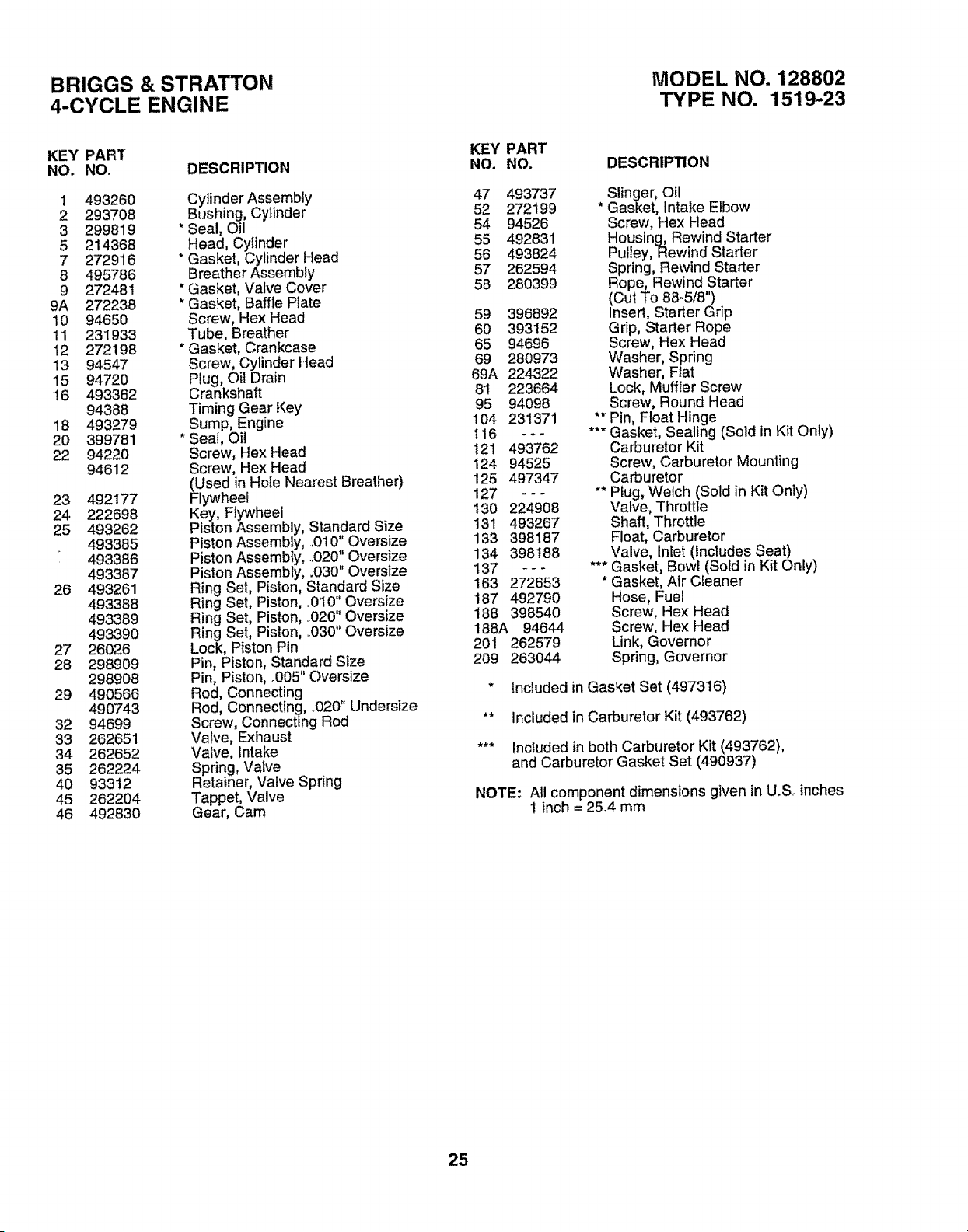
BRIGGS & STRATTON
4-CYCLE ENGINE
MODEL NO, 128802
TYPE NO, 1519..23
KEY PART
NO. NO. DESCRIPTION
1 493260
2 293708
3 299819
5 214368
7 272916
8 495786
9 272481
9A 272238
10 94650
11 231933
12 272198
13 94547
15 94720
!6 493362
94388
18 493279
20 399781
22 94220
94612
23 492177
24 222698
25 493262
493385
493386
493387
26 493261
493388
493389
493390
27 26026
28 298909
298908
29 490566
490743
32 94699
33 262651
34 262652
35 262224
40 93312
45 262204
46 492830
Cylinder Assembly
Bushing, Cylinder
* Seal, Oil
Head, Cylinder
* Gasket, Cylinder Head
Breather Assembly
* Gasket, Valve Cover
* Gasket, Baffle Plate
Screw, Hex Head
Tube, Breather
* Gasket, Crankcase
Screw, Cylinder Head
Plug, Oil Drain
Crankshaft
Timing Gear Key
Sump, Engine
Seal, Oil
Screw, Hex Head
Screw, Hex Head
(Used in Hole Nearest Breather)
Flywheel
Key, Flywheel
Piston Assembly, Standard Size
Piston Assembly, .,010" Oversize
Piston Assembly, .,020" Oversize
Piston Assembly, .030" Oversize
Ring Set, Piston, Standard Size
Ring Set, Piston, .010 Oversize
Ring Set, Piston, ..020" Oversize
Ring Set, Piston, .O30" Oversize
Lock, Piston Pin
Pin, Piston, Standard Size
Pin, Piston, °005" Oversize
Rod, Connecting
Rod, Connecting, °020" Undersize
Screw, Connecting Rod
Valve, Exhaust
Valve, Intake
Spring, Valve
Retainer, Valve Spring
Tappet, Valve
Gear, Cam
KEY PART
NO. NO. DESCRIPTION
47 493737 . Slinger, Oil
52 272199 Gasket, Intake Elbow
54 94526 Screw, Hex Head
55 492831 Housing, Rewind Starter
56 493824 Pulley, Rewind Starter
57 262594 Spring, Rewind Starter
58 280399 Rope, Rewind Starter
(Cut To 88-5t8")
59 396892 Insert, Starter Grip
60 393152 Grip, Starter Rope
65 94696 Screw, Hex Head
69 280973 Washer, Spring
69A 224322 Washer, Fiat
81 223664 Lock, Muffler Screw
95 94098 Screw, Round Head
104 23!371 ** Pin, Float Hinge
116 - - - *** Gasket, Sealing (Sold in Kit Only)
121 493762 Carburetor Kit
124 94525 Screw, Carburetor Mounting
125 497347 Carburetor
127 - - - ** P_ug, Welch (Sold in Kit Only)
130 224908 Valve, Throttle
131 493267 Shaft, Throttle
133 398187 Float, Carburetor
134 398188 Valve, Inlet (Includes Seat)
137 - - - *** Gasket, Bowl (Sold in Kit Only)
t63 272653 * Gasket, Air Cleaner
187 492790 Hose, Fuel
188 398540 Screw, Hex Head
188A 94644 Screw, Hex Head
201 262579 Link, Governor
209 263044 Spring, Governor
* Included in Gasket Set (497316)
** Included in Carburetor Kit (493762)
*** Included in both Carburetor Kit (493762),
and Carburetor Gasket Set (490937)
NOTE: All component dimensions given in U.So inches
1 inch = 25.4 mm
25
BRIGGS & STRATTON
4-CYCLE ENGINE
MODEL NO. 128802
TYPE NO. 1519-23
KEY PART
NO. NO. DESCRIPTION
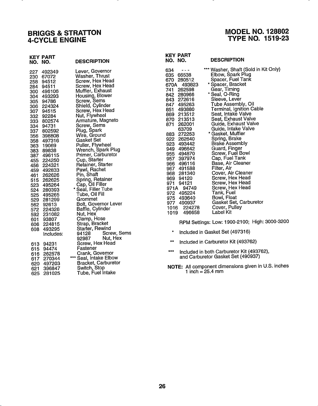
227 492349
230 67072
258 94512
284 94511
300 496106
304 493293
305 94786
306 224324
307 94515
332 92284
333 802574
334 94731
337 802592
356 398808
358 497316
363 19069
383 89838
387 496115
455 224250
456 224321
459 492833
461 262626
515 262625
523 495264
524 280393
525 495265
529 281299
562 92613
572 224328
592 231O82
601 93807
606 224815
608 493295
Includes:
613 94231
6!5 94474
616 262578
617 270344
620 497203
621 396847
625 281025
Lever, Governor
Washer, Thrust
Screw, Hex Head
Screw, Hex Head
Muffler, Exhaust
Housing, Blower'
Screw, Seres
Shield, Cylinder
Screw, Hex Head
Nut, Flywheel
Armature, Magneto
Screw, Seres
Plug, Spark
Wire, Ground
Gasket Set
Puller, Flywheel
Wrench, Spark Plug
Primer, Carburetor
Cup, Starter
Retainer, Starter
Pawl, Rachel
Pin, Shaft
Spring, Retainer
Cap, Oil Filier
* Seal, Filler' Tube
Tube, Oil Fill
Grommet
Bolt, Governor Lever
Baffle, Cylinder'
Nut, Hex
Ctamp, Hose
Strap, Bracket
Starter, Rewind
94128 Screw, Sems
92987 Nut, Hex
Screw, Hex Head
Fastener'
Crank, Governor
*** Seal, Intake Elbow
Bracket, Carburetor
Switch, Stop
Tube, Fuel intake
KEY PART
NO. NO. DESCRIPTION
634 - - - *** Washer, Shaft (Sold in Kit Only)
635 66538 Elbow, Spark Plug
670 280512 Spacer, Fuel Tank
670A 493823 * Spacer', Bracket
741 262598 Gear', Timing
842 280966 * Seal, O-Ring
843 272616 Sleeve, Lever
847 495263 Tube Assembly, Oil
851 493880 Terminal, Ignition Cable
869 213512 Seat, Intake Valve
870 213513 Seat, Exhaust Valve
871 262001 Guide, Exhaust Valve
63709 Guide, Intake Valve
883 272253 * Gasket, Muffler
922 262640 Spring, Brake
923 493442 Brake Assembly
949 496642 Guard, Finger
955 494870 Screw, Fuel Bowl
957 397974 Cap, Fuel Tank
966 496116 Base, Air Cleaner
967 491588 Filter, Air
968 281340 Cover, Air Cleaner
969 94120 Screw, Hex Head
971 94121 Screw, Hex Head
971A 94749 Screw, Hex Head
972 495224 Tank, Fuel
975 493640 Bowl, Float
977 490937 Gasket Set, Carburetor
1016 224278 Cover, Pulley
1019 496658 Label Kit
RPM Settings: Low: 1900-2100; High: 3000-3200
* Included in Gasket Set (497316)
** Included in Carburetor Kit (493762)
*** tncluded in both Carburetor Kit (493762),
and Carburetor Gasket Set (490937)
NOTE: All component dimensions given in U.S. inches
1 inch = 25.4 mm
26

i, i iiii ill i ii,l,,i, iill iil,ii illl ,ill i lllll
TROUBLESHOOTING POINTS
PROBLEM
Does not start
....................................... ii ii
Loss of power
....................................... illl
Poor cut - uneven
Excessive vibration
_,_,:_............. iiiiiilllllll illlll
Starter rope hard to pull
Loss of drive
(Self-Propelled Mowing)
,,, ....................,,, ,_,,,,,,,,,,,_ :_
Grass catcher not filling
(If so equipped)
Hard to push
CAUSE
1., Dirty air filter,,
2, Out of fuel.
3, Stale fuel,
4, Water in fuel.
5. Spark plug wire is disconnected
6. Bad spark plug
7, Loose blade or broken blade adapter,,
8, Control bar in released position
9o Control bar defective
t. Rear of lawn mower housing/blade dragging
In heavy grass.
2 Cutting too much grass
3, Dirty air filter.,
4., Buildup of grass, leaves and trash under mower.
5, Too much oil in engine,
6., Walking speed too fast,,
!, Worn, bent or loose blade
2. Wheel heights uneven
3, Low engine speed.
4_ Buildup of grass, leaves, and trash under mower°
!, Worn, bent or loose blade
2, Bent engine crankshaft.,
1. Engine flywheel brake is on when control bar is
released
2 Bent engine crankshaft
3_ BIade adapter broken,,
4r Blade dragging in grass,
1. Ddve wheels not turningwith ddve control engaged
2, Belt not driving
!_ Cutting hetght too low
2 Lift on blade worn off
3. Catcher not venting air,
4., Low engine speed,,
............_,_ ill i, i ii
t, Grass is too high or wheel height is too lowo
2, Rear of lawn mower housing/blade dragging
{n grass.,
3, Grass catcher too fuff
4. Handle height position not right for you,,
CORRECTION
1, Clean/replace air filter,
2, FH!fuel tank.,
3 Drain tank and refill with fresh clean fuel
4., Drain fuel tank and carburetorand refiil tank with fresh
gasoline
5. Connect wire to plug.
6, Replace spark plug.,
7. Tighten blade bolt or replace blade adapter
8. Depress control bar to handle,
9. Replace control bar,
1_ Set in "Higher Cut" position.,
2. Set in"Higher Cut" position
3. Clean!replace air filter.
4_ Clean underside of mower housing
5r Check oil level,,
6, Cut at slower walking speed
2.
3,
4-
Replace blade., Tighten blade belt
Set el!wheels at same height,
Set engine speed control infast position.,
Clean underside of mower housing
I Replace blade., Tighten blade bolt
2 Contact an authorized service centerldepartment,
1,, Depress control bar to upper handle before
pulling starter rope,
2., Contact an authorized service center/department,
3 Replace blade adapter.,
4,, Move lawn mower to cut grass or to hard surface
to start engine,
1. Adjust or replace drive contro[ cable, if broken.
2,. Put belt on pulleys or replace belts if broken_
1. Raise cutting height..
2, Replace blade.
3. Clean grass catcher,
4. Set engine speed controt tn fast position.,
1, Raise cutting height.,
2 Raise rear of fawn mower housing one (1)
setting higher
3 Empty grass catcher,,
4 Adjust handle height to suit
27
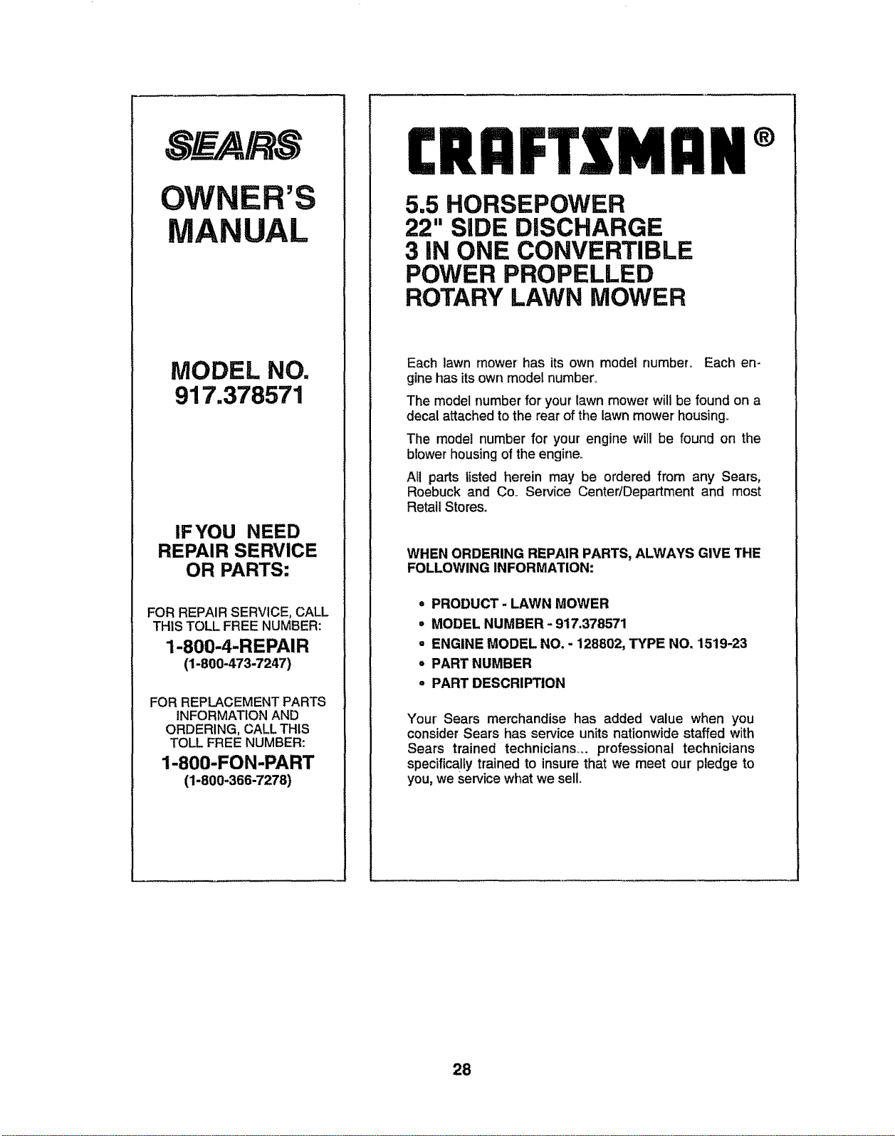
OWNER'S
MANUAL
MODEL NO.
917.378571
IF'YOU NEED
REPAIR SERVICE
OR PARTS:
FOR REPAIR SERVICE, CALL
THIS TOLL FREE NUMBER:
1-800-4-REPAIR
(1-800-473-7247)
FOR REPLACEMENT PARTS
INFORMATION AND
ORDERING, CALL THIS
TOLL FREE NUMBER:
1-800-FON-PART
(1-800-366-7278)
CRAFTS I:IN®
5.5 HORSEPOWER
22" SiDE DISCHARGE
3 IN ONE CONVERTIBLE
POWER PROPELLED
ROTARY LAWN MOWER
Each lawn mower has its own model number.. Each en-
gine has itsown model number_
The model number for your lawn mower will be found on a
decal attached to the rear of the lawn mower housing.
The model number for your engine will be found on the
blower housingof the engine
AU parts listed herein may be ordered from any Sears,
Roebuck and Co.. Service Center/Department and most
Retail Stores.
WHEN ORDERING REPAIR PARTS, ALWAYS GIVE THE
FOLLOWING INFORMATION:
• PRODUCT- LAWN MOWER
= MODEL NUMBER - 917.378571
= ENGINE MODEL NO. - 128802, TYPE NO, 1519-23
= PART NUMBER
° PART DESCRIPTION
Your' Sears merchandise has added value when you
consider Sears has service units nationwide staffed with
Sears trained technicians .... professional technicians
specifically trained to insure that we meet our pledge to
you, we service what we sell
28
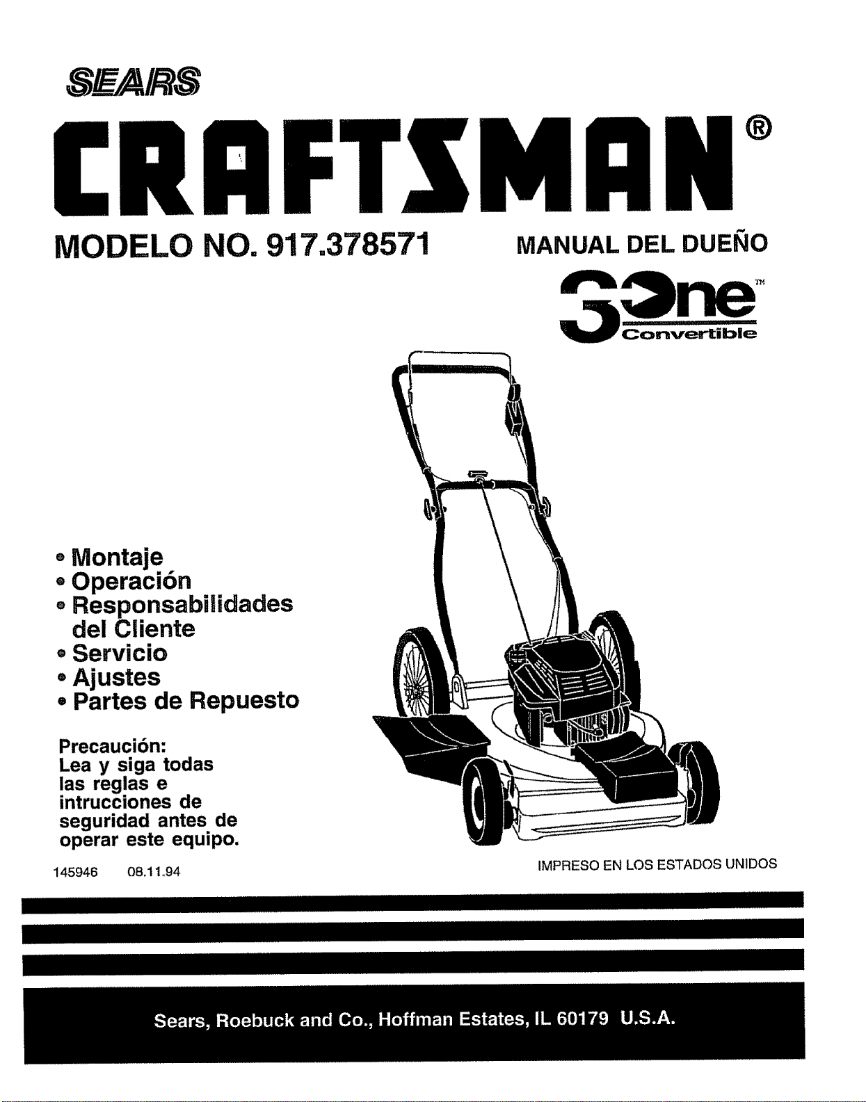
MODELO NO. 917.378571
MANUAL DEL DUEllO
Convertible
° Montaje
- Operaci6n
®Responsabilidades
del Cliente
=Servicio
=Ajustes
• Partes de Repuesto
Precaucibn:
Lea y siga todas
ias reglas e
intrucciones de
seguridad antes de
operar este equipo.
145946 08.11.94
IMPRESO EN LOS ESTADOS UN1DOS
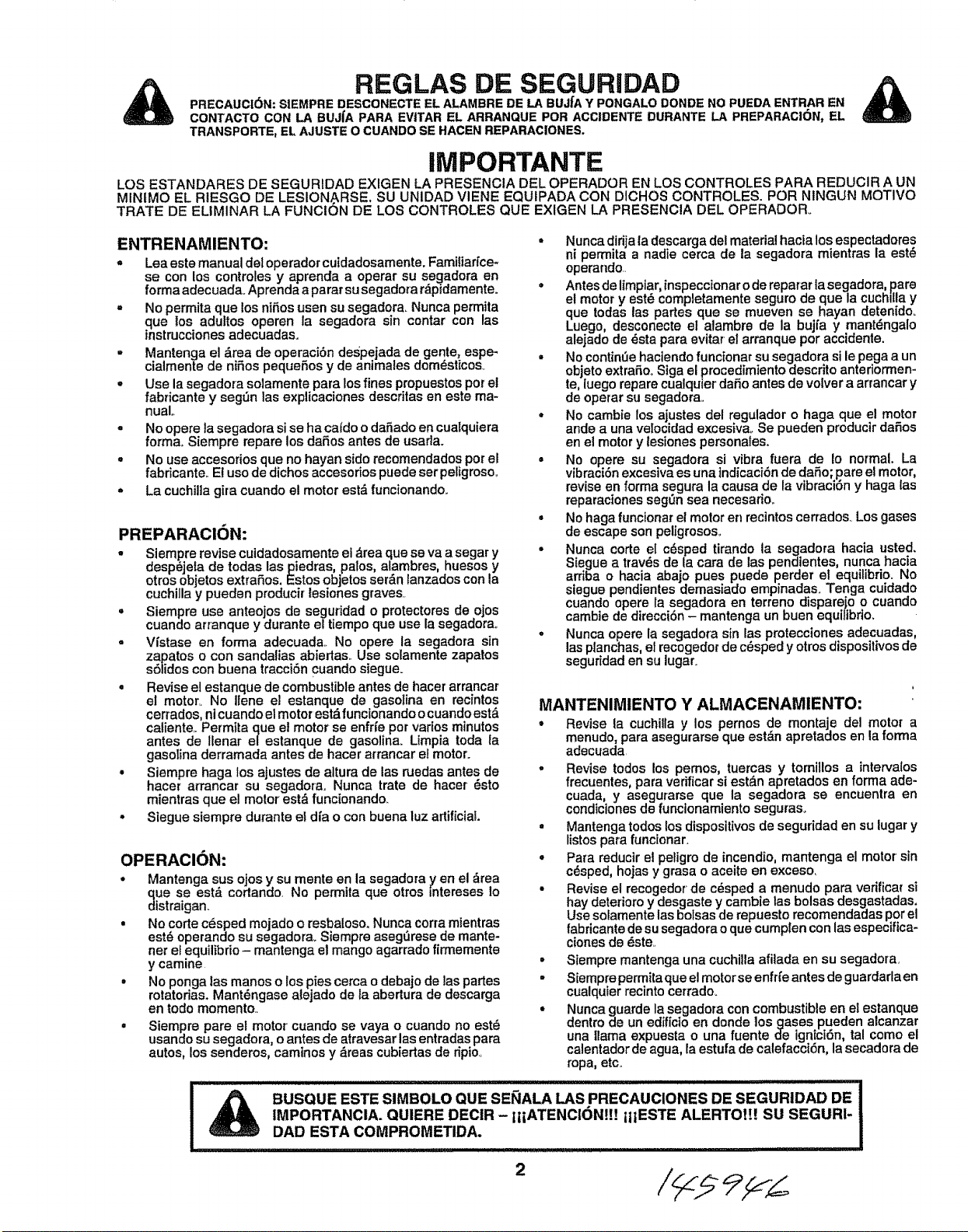
&
REGLAS DE SEGURIIDAD
PRECALICI6N: S|EMPRE DESCONECTEEL ALAMBREDE LA BUJfAY PONGALODONDE NOPUEDA ENTRAR EN
CONTACTO CON LA BUJfA PARA EVITAR EL ARRANQUE POR ACCIDENTE DURANTE LA PREPARACI6N, EL
TRANSPORTE, EL AJUSTE O CUANDOSE HACENREPARAClONES.
iMPORTANTE
LOS ESTANDARES DE SEGURIDAD EXIGEN LA PRESENCtA DEL OPERADOR EN LOS CONTROLES PARA REDUCIR A UN
MINtMO EL RIESGO DE LESION_RSE. SU UNIDAD VIENE EQUIPADA CON DICHOS CONTROLES. POR NINGUN MOTIVO
TRATE DE ELIMINAR LA FUNCION DE LOS CONTROLES QUE EXIGEN LA PRESENCIA DEL OPERADOR.
ENTRENAMIENTO:
- Lea este manual det operador cuidadosamente. Familiarfce+
se con los controles y aprenda a operar su segadora en
forma adecuada. Aprenda a parar su segadora rdpidamente.
- No permita que los niSos usen su segadora. Nunca perrnita
que los adultos operen la segadora sin contar con las
instrucciones adecuadas,
• Mantenga el _.rea de operaciSn despejada de gente, espe-
cia mente de nifios pequeSos y de animales dom_sticos+
• Use la segadora solamente para los fines propuestos per el
fabricante y seg_n las explicaciones descritas en este ma-
nual,,
• No opere ta segadora si se ha catdo o dafiado en cualquiera
forma+ Siempre repare los daSos antes de usarla+
= No use accesorios que no hayan side recomendados per el
fabricante+ El use de dichos accesodos puede ser peligroso..
- La cuchilla gira cuando el motor est_ funcionando..
PREPARACI(_N:
- Siempre revise cuidadosamente el _rea que se va a segar y
desp_jela de todas las piedras palos, alambres, huesos y
otros objetos extraSos. Estos objetos ser_n lanzados con a
cuchilla y pueden producir lesiones graves+
= Siempre use anteojos de seguridad o protectores de ojos
cuando atranque y durante el tiempo que use la segadora+_
• Vistase en forma adecuada.. No opere la segadora sin
zapatos o con sandalias abiertas.. Use solamente zapatos
s61idos con buena tracci6n cuando siegue.
° Revise el estanque de combustible antes de hacer arrancar
el motor.. No llene el estanque de gasolina en recintos
cerrados, nicuando el motor est& funcionando o cuando est&
caliente.. Permita que el motor se enfrie per varies minutes
antes de Ilenar el estanque de gasolina. Umpia toda ta
gasolina derramada antes de hacer arrancar el motor.
• Siempre haga los ajustes de aitura de las ruedas antes de
hacer armncar su segadora. Nunca trate de hacer _sto
mientras que el motor est& func[onando+
° Stegue siempre durante et dia o con buena luz artificial
OPERACION:
° Mantenga sus ojos y su mente en la segadora yen el _rea
que se est& cortando. No permita que otros +ntereses lo
distraigan+
• No corte c6sped mejado o resbaloso. Nunca corra mientras
est6 operando su segadora+ Siempre aseg_rese de mante-
net el equilibdo- mantenga el mango agarrado firmemente
y camine
, No ponga Ias manes o los pies cerca o debajo de las partes
rotatodas+ Mant_ngase alejado de la abertura de descarga
en rode memento..
• Siempre pare el motor cuando se vaya o cuando no est_
usando su segadora, o antes de atravesar las entradas para
autos, los senderos, caminos y _reas cubiertas de ripio.,
° Nunca dirija la descarga del material hacia los espectadores
ni permita a nadie cerca de la segadora mientras la est_
operando..
• Antes de limpiar, inspeccionar o de reparar la segadora, pare
el motor y est_ completamente seguro de que la cuchilla y
que todas las partes que se mueven se hayan detenido.
Luego, desconecte el atambre de la bujt'a y mant_ngalo
alejado de _sta para evitar el arranque per accidente.
° No contint3e haciendo funcionar su segadora si le pega a un
objeto extraSo.. Siga el procedimiento descrito anteriormen-
te, [uego repare cualquier daSo antes de volver a arrancar y
de operar su segadora..
• No cambie los ajustes del regulador o haga que el motor
ande a una velocidad excesiva+ Se pueden producir daSos
en el motor y lesiones personales.
= No opere su segaclora si vibra fuera de Io normal. La
vibraciSn excesiva es una tndicaci6n de daSo; pare el motor,
revise en forma segura la causa de la vibraci6n y haga las
reparaciones segOn sea necesario_
° No haga funeionar el motor er_recintos cerrados_ Los gases
de escape son peligrosos+
• Nunca eorte el c_sped tirando la segadora haeia usted.
Siegue a trav_s de la cara de las pendientes, nunca hacia
arriba o hacia abajo pues puede perder el equilibrio. No
siegue pendientes demasiado empinadas+ Tenga cutdado
cuando opere la segadora en terreno disparejo o cuando
cambie de direcciSn - mantenga un buen equitibdo+
• Nunca opere la segadora sin las protecciones adecuadas,
las planchas, el recogedot de c_sped y otros dispositivos de
seguridad en su lugar+
MANTENIMIENTO Y ALMACENAMIENTO"
• Revise la cuchilla y los pernos de montaje del motor a
menudo, para asegurarse que est_n apretados en la forma
adecuada.
, Revise todos los pemos, tuercas y tomillos a intervalos
frecuentes, para verificar si est_n apretados en forma ade-
cuada, y asegurarse que la segadora se encuentra en
condiciones de funcionamiento seguras+
• Mantenga todos los dispositivos de seguridad en su lugar y
listos para funcionar+
° Para reducir el peligro de incendio, mantenga el motor sin
c_sped, hojas y grasa o aeeite en exceso,
= Revise el reeogedor de c_sped a menudo para verifiear si
hay deterioro y desgaste y cambie las bolsas desgastadas.
Use soramente las bolsas de repuesto recomendadas per el
fabricante de su segadora o que cumplen con las especifica-
ciones de _ste.+
• Siempre mantenga una cuchiila afilada en su segadora.
• Siemprepermita que el motorse enfrt'e antes de guardarla en
cualquter recinto cer_'ado+
• Nunca guarde la segadora con combustible en el estanque
dentro de un edificio en donde los gases pueden alcanzar
una llama expuesta o una fuente de ignici6n, tal come el
calentador de agua, la estufa de ealefacei6n, la secadora de
ropa, etc.
BUSQUE ESTE SIMBOLO QUE SE_IALA LAS PRECAUCIONES DE SEGURIDAD DE
IMPORTANCIA. QUIERE DECiR - IIiATENCI(3NLI! ilIESTE ALERTOt[! SU SEGURI-
DAD ESTA COiVlPROMETIDA.
2
FELICITACIONES porla comprade su segadora SearsCraftsmam
Ha sido diseSada, planificada y fabricada para darle la mejor
confiabilidad y el mejor rendimiento posibleso
En et caso de que se encuentre con cualquier problema que no
pueda solucionarfdcilmente, haga elfavor de ponerse en contac-
to con su CentrolDepadamento de Servicio Sears m&scercano.
Sears cuenta contdcnicos bien capacitados y competentes y con
lasherramtentas adecuadas para darle servicio o para reparar su
unidad.
Haga et favor de leer y de guardar este manual Estas instruccio-
nee le permitirdn montar y mantener su segadora en forma
adecuada. Siempre observe las "REGLAS DE SEGURtDADo"
NOMERO DE
MODELO
NUMERO DE
SERIE
917.378571
FECHA DE
COMPRA
EL NOMERO DEL MODELO Y EL DE SERIE SE ENCUEN-
TRAN EN LA CALCOMANIA ADJUNTA A LA PARTE TRA-
SERA DE LA CAJA DE LA SEGADORA.
DEBE REGISTRAR TANTO EL NUMERO DE SERIE COMO
LA FECHA DE COMPRA Y MANTENGALOS EN UN LUo
GAR SEGURO PARA REFERENClA EN EL FUTUROn
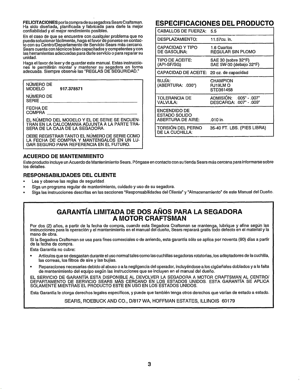
ESPECIFICAClONES DEL PRODUCTO
CABALLOS DE FUERZA: 55
DESPLAZAMIENTO: 11o57cuoin,
CAPACIDAD Y TIPO 1.,6Cuartos
DE GASOLINA: REGULAR SIN PLOMO
TIPO DE ACEITE: SAE 30 (sobre 32°F)
(AP!-SFtSG) SAE 5W-30 (debajo 32°F)
CAPAClDAD DE ACEITE: 20 ozode capacidad
BUJfA: CHAMPION
(ABERTURA: ,030") RJ19LM O
STD361458
TOLERANCIA DE ADMtSK_N: .005" - .007"
VALVULA: DESCARGA: ,007" - ,,009"
ENCENDIDO DE
ESTADO SOLIDO
ABERTURA DE ArRE: ,,010 in,
TORSION DEL PERNO 35-40 FT, LBSo (PIES LIBRA)
DE LA CUCHILLA:
ACUERDO DE MANTENIMIENTO
Este productoincluye unAcuerdo de Mantenimiento Sears..P6ngase en contactocon sutienda Sears mdscercana para informarse sobre
los detalles.
RESPONSABILIDADES DEL CLIENTE
• Lea y observe las reglas de seguddad.
° Siga un programa regular de mantenimiento, cuidado y uso de su segadorao
• Siga las instrucciones descritas en las secciones "Responsabilidades del Cliente" y "Almacenamiento" de este Manual del DueSo_
GARANTfA LIMITADA DE DOS ANOS PARA LA SEGADORA
A MOTOR CRAFTSMAN
Por dos (2) afios, a partir de la fecha de compra, cuando esta Segadora Craftsman se mantenga, lubrique y afine segun las
instnJccionespara la operact6n y el mantenimiento en e_manual del duefio, _ears reparar&gratis todo defecto en el material y la
mane de obrao
Si ia Segadora Crattsman se usa para fines comerciales o de arriendo, esta garanffa s61ose aplica por noventa (90) dt'asa partir
de la fecha de compra.
Esta Garanffa no cubre:
• Art[culos que se desgastan durante el uso normaltalescornolas cuchillas segadoras rotatorias,los adaptadores de la cuchilta,
las correas, los filtros de aire y las bujt'as.
• Reparaciones necesarias debidoal abuso o a la negligencia det operador, incluy_ndosea los cigeeSales doblados y a la falta
de mantentmiento del equipo seg_n las instruccionesque se incluyen en et manual del duefio..
EL SERVIC10 DE GARANT[A ESTA DISPONIBLE AL DEVOLVER LA SEGADORA A MOTOR CRAFTSMAN AL CENTRO/
DEPARTAMENTO DE SERVICfO SEARS M/_S CERCANO EN LOS ESTADOS UNtDOS. ESTA GARANTIA SE APLICA
SOLAMENTE MIENTRAS EL PRODUCTO ESTE EN USO EN LOS ESTADOS UNIDOS,
Esta Garantta Ie otorga derechos legales especfficos,y puede que tambi_n tenga otros derechos que vadan de estado a estadoo
SEARS, ROEBUCK AND CO., D/817 WA, HOFFMAN ESTATES, ILLINOIS 60'I79
3
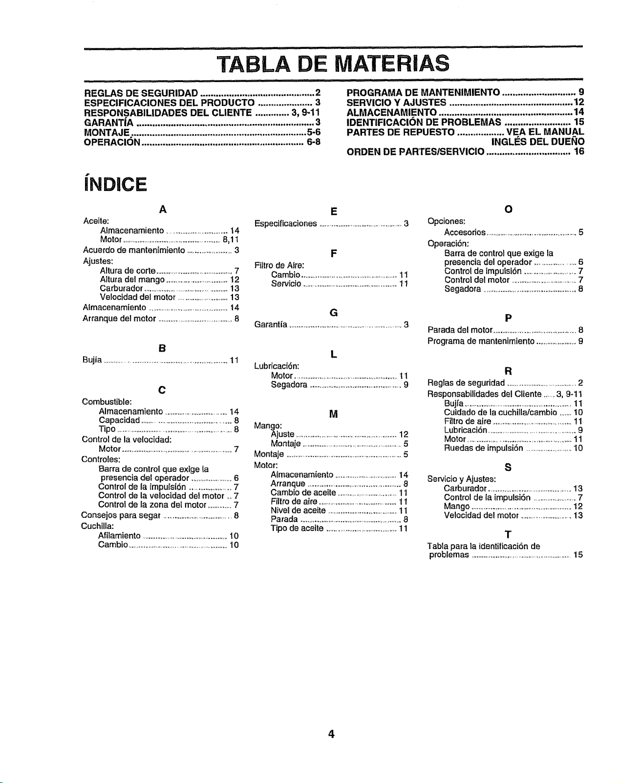
AS
REGLAS DE SEGUR|DAD ............................................ 2
ESPECIFICACIONES DEL PRODUCTO ..................... 3
RESPONSABILIDADES DEL CLIENTE ............. 3, 9-11
GARANTiA .................................................................... 3
MONTAJE ................................................................... 5-6
OPERACION .............................................................. 6-8
PROGRAMA DE MANTENIMIENTO ............................ 9
SERVICIO Y AJUSTES ............................................... 12
ALMACENAMIENTO ................................................... 14
IDENTIFICACI6N DE PROBLEMAS ......................... 15
PARTES DE REPUESTO .................. VEA EL MANUAL
INGLI_S DEL DUEI_IO
ORDEN DE PARTEStSERVICIO ................................ 16
|ND|CE
A
Aceite:
Almacenamiento ........................... t4
Motor ............................................................8,11
Acuerdo de mantenimiento .........................3
Ajustes:
Altura de corte ..............................................7
Aitura del mango ...................................12
Carburador .....................................................13
Velocidad del motor, ............................13
Atmacenamiento ...........................................14
Arranque del motor .............................................8
B
Bujia .............................................................................11
C
Combustible:
Almacenamiento ...................................14
Capacidad .........................................................8
Tipo .................................................................8
Control de la velocidad:
Motor ....................................................................7
Controles:
Barra de control que extge la
presencia del operador ...........................6
Control de la impulsidn ......................7
Control de la velocidad dot motor ,,,,7
Control de la zona del motor ..............7
Consejos para segar ..................................8
Cuchilla:
Af!lamiento ...............................................I0
Cambio ....................................................................10
E
Especificaciones .......................................................3
F
Filtro de Alto:
Cambio ..............................................................11
Servicio ....................................................11
G
Garanfla ...............................................................3
L
Lubricacidn:
Motor ..............................................................11
Segadora ....................................................9
M
Mango:
Ajuste ..............................................................12
Montaje ...................................................................5
Montaje ......................................................................5
Motor:
Almacenamiento ..........................................14
Arranque ..................................................8
Cambio de aceite ........................................11
Fil/ro de aire ..............................................11
Nivel de aceite .........................................11
Parada ..............................................................8
Tipo de aceite ......................................11
O
Opciones:
Accesodos ........................................................5
Operaci6n:
Barra de control que exige la
presencia del operador ........................6
Control de impulsidn ................................7
Control del motor .........................................7
Segadora ................................................8
P
Parada del motor ........................................8
Programa de mantenimiento ....................9
R
Reglas de seguddad ...........................................2
Responsabitidades del Cliente ........3, 9-11
Bujfa ............................................................11
Cutdado de la cuchilla/cambio ...... 10
Filtro de aire ..........................................11
Lubflcaci6n .........................................................9
Motor ..........................................................t 1
Ruedas de impulsi6n ................................10
S
SerJicio y Ajustes:
Carburador
..............................................
13
Control de la impulsiSn .............................7
Mango .........................................................12
Velocidad del motor ...............................13
T
Tabla para la identifioaci6n de
problemas .......................................................15
4
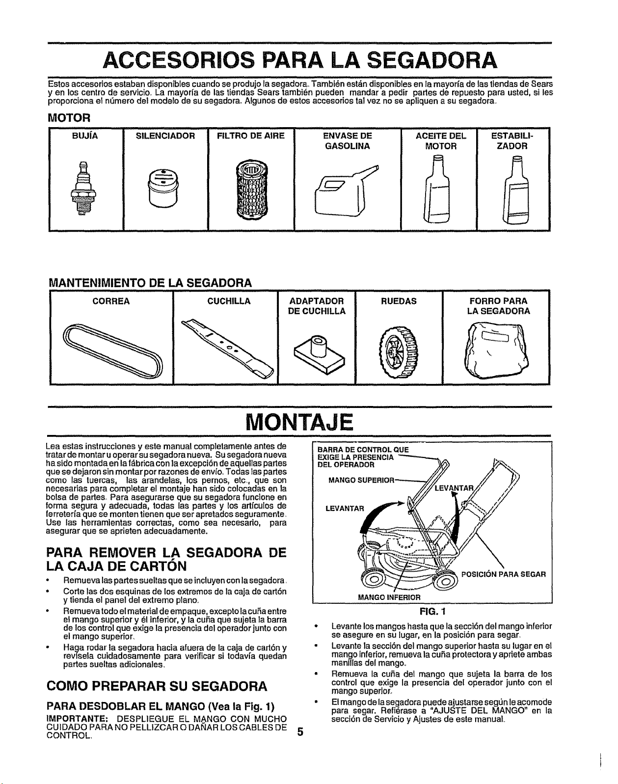
...........-:: i i iilll,iiill,l,,i ]llll,i .......... :: : ...... , ............................ .........................
ACC PARA LA SEGADORA
Estos accesorios estaban disponibtes cuando se produjo la segadora,. Tambi_n estdn disponibles en la may0r_a de las tlendas de Sears
yen los centre de servtcio.. La mayorfa de las tiendas Sears tambi_,n pueden mandar a pedtr pares de repuesto para usted, si les
proporciona el nemero del modelo de su segadora. Algunos de estos accesorios tel vez no se apliquen a su segadora.
MOTOR
StLENCIADORBUJ[A FILTRO DE AIRE ENVASE DE
GASOLINA
ACEtTE DEL
MOTOR
ESTABILI-
ZADOR
MANTENIMIENTO DE LA SEGADORA
Lea estas instrucciones y este manual completamente antes de
tratar de reenter u operar su segadora nueva. Su segadora nueva
ha side montada en la f_,bricacon la excepci6n de aquellas partes
que se dejaron sin montar per razones de envfo.,Todas taspartes
come las tuercas, las arandelas, los pemos, etc., que son
necesarias pare completer el montaje han side colocadas en la
boise de parles_ Para asegurarse que su segadora functone en
forma segura y adecuada, todas las partes y los adfcules de
ferreteri'a que se monten tienen que ser apretados seguramente,
Use las herramientas correctas, come sea necesario, para
asegurar que se aprieten adecuadamente.
PARA REMOVER LA SEGADORA DE
LA CAJA DE CARTON
• Remueva laspartes sueltas que se incluyencon lasegadora.
• Code las dos esquinas de los extremes de la caja de cart6n
y tienda el panel del extreme piano..
• Remueva todo e!material de empaque, excepto la cuba entre
el mango superior y _l inferior, y la curia que sujeta Ia barra
de los control que exige la presencia del operador junto con
el mango supenor..
• Haga rodar ia segadora hacia afuera de la caja de cad6n y
revfseta culdadosamente para verificar si todavia quedan
partes sueltas adicionales_
COMe PREPARAR SU SEGADORA
PARA DESDOBLAR EL MANGO (Vea la Fig. 1)
IMPORTANTE: DESPL1EGUE EL M_NGO CON MUCHO
CUIDADO PARA NO PELLIZCAR O DANAR LOS CABLES DE
CONTROL,
BARRA DE CONTROL QUE
EXtGE LA PRESENCIA
DEL OPERADOR
LEVANTAR
POSICION PARA SEGAR
5
MANGO INFERIOR
FIG. 'I
• Levante los mangos hasta que la secci6n del mango inferior
se asegure en su lugar, en la posici6n para segar_
• Levante la secci6n del mango superior haste su lugar en el
mango inferior, remueva la cuSa protectora y apriete ambas
manflfas del mango°
= Remueva la cuSa del mango que sujeta la barra de _os
control que exige la presencia deI operador junto con el
mango supenoro
• E! mango de lasegadora puede ajustarse segen le acomode
para segar. Refi_rase a "AJUSTE DEL MANGO en la
secci(_n de Servicio y Ajustes de este manual
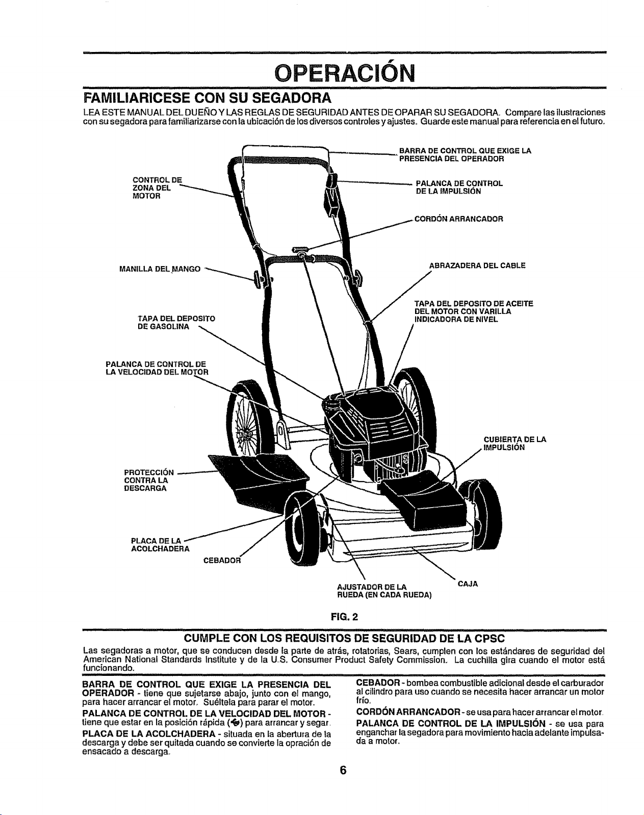
OPERACION
FAMILIARICESE CON SU SEGADORA
LEA ESTE MANUAL DEL DUE_O Y LAS REGLAS DE SEGURIDAD ANTES DE OPARAR SU SEGADORA.. Compare las iiustraciones
consu segadora para familiarizarse con la ubicaci6n de losdiversos controlesy ajustes, Guarde este manual para referencia en el futuro.
CONTROL DE
ZONA DEL
MOTOR
BARRA DE CONTROL QUE EXIGE LA
PRESENCIA DEL OPERADOR
PALANCA DE CONTROL
DE LA JMPULSI6N
MANILLA DEL MANGO
TAPA DEL DEPOS|TO
DE GASOL|NA
PALANCA DE CONTROL DE
LA VELOCIDAD DEL MOTOR
ABRAZADERA DEL CABLE
TAPADELDEPOSITO DE ACEITE
DELMOTORCON VARILLA
INDICADORA DE NIVEL
CUBIERTA DE LA
IMPULSION
PROTECCI6N
CONTRALA
DESCARGA
PLACA DE LA
ACOLCHADERA
CEBADOR
AJUSTADOR DE LA
RUEDA(EN CADA RUEDA)
CAJA
FIG. 2
.............. CUr PLECO.LOSREOUlSlTOSDESEGURIOADDELACPSC ".....
Las segadoras a motor, que se conducen desde la parte de atr_s, rotatodas Sears, cumplen con los estdndares de seguridad de!
American Nat onal Standards Institute y de la U.So Consumer Product Safety Commission. La cuchilla gira cuando el motor est,.
func{onando.
11/illll i ill = i ilJlllllllll i =ill= = i,ll, ,ll,ll,i ........ ......
BARRA DE CONTROL QUE EXIGE LA PRESENCIA DEL
OPERADOR - tiene que sujetarse abajo, junto con el mango,
para hacer arrancar el motor,. Su_ltela para parar el motor.
PALANCA DE CONTROL DE LA VELOClDAD DEL MOTOR -
tiene que estar en la posici_n rdpida (,t_) para arrancar y segar.
PLACA DE LA ACOLCHADERA - situada en ia abertura de la
descarga y debe ser quitada cuando se convierte ia opraci6n de
ensacado a descarga..
CEBADOR- bombea combustibleadicional desde el carburador
al ciUndropara uso cuando se necesita hacer arrancar un motor
fr{o,
CORDON ARRANCADOR- se usa para hacer arrancar el motor.
PALANCA DE CONTROL DE LA IMPULS|ON - se usa para
enganchar la segadora para movimiento hacia adelante impulsa-
da a motor_
6
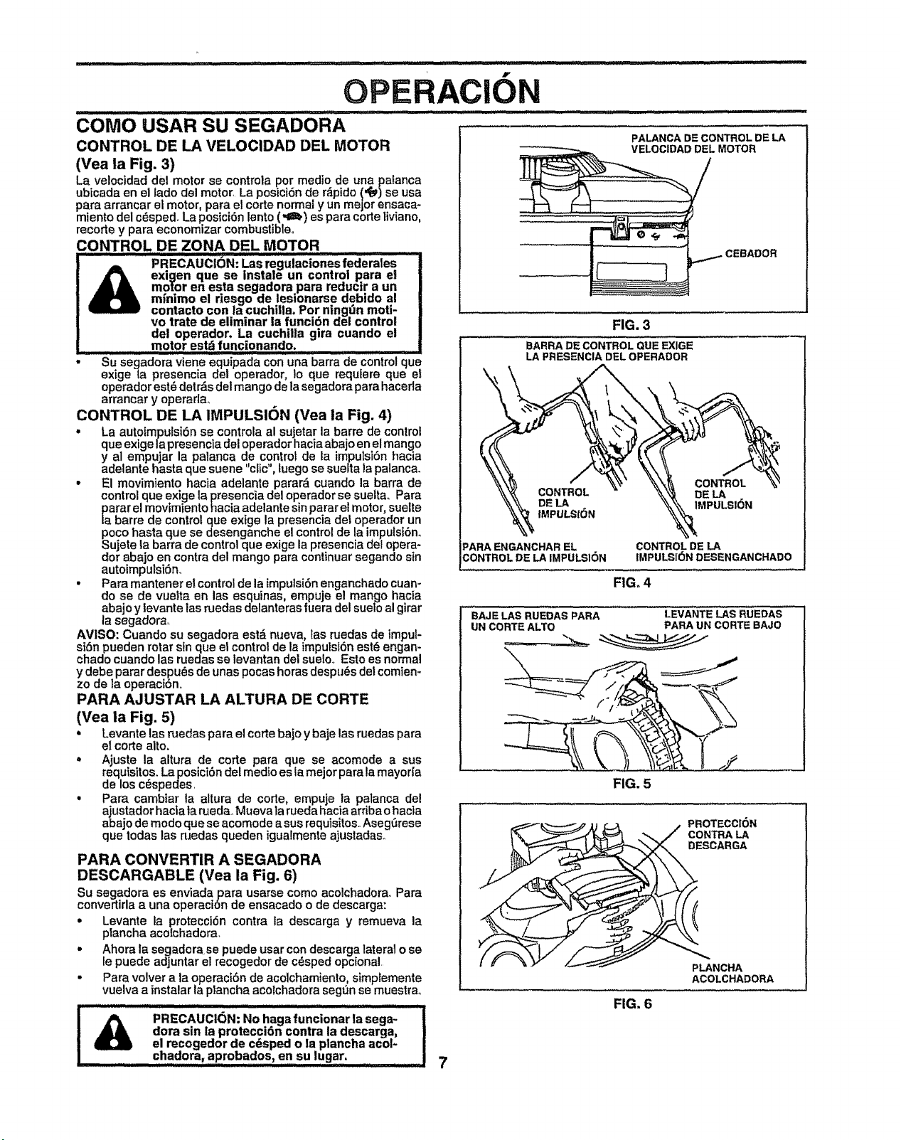
come USAR SU SEGADORA
CONTROL DE LA VELOClDAD DEL MOTOR
(Vea la Fig. 3)
La velocidad del motor se controla per medio de una palanca
ubicada en el lade del motor, La posici6n de r_pido ('#e_)se usa
para arrancar el motor, para el corte normal y un major ensaca-
miento del c_sped_ La posici6n lento (*gl.) es para corte liviano,
recorte y para economlzar combustible.
CONTROL DE ZONA DEL MOTOR
" ...........................PRECAUCION; I.as re.gulaci0nes federates
exigen qua se instale un control para el
motor en esta segaaora para reaucir a un
m_nimo el riesgo de lesionarse debido al
contacto con la cuchilla. Per n|ngt_n moti-
ve trate de eliminar la funciSn del control
del operador. La cuchilla gira cuando el
motor estd funcionando.
* Su segadora viene equipada con una barra de control qua
exige la presencia del operador, Io que requlere que el
operador est_ detrds del mango de la segadora para haceda
arrancar y operadao
CONTROL DE LA IMPULSION (Vea la Fig. 4)
, La autoimpulsi6n se controla al sujetar la barre de control
qua exige la presencla del operador hacia abajo en e! mango
y al empujar la palanca de control de la imputsi6n hacia
adelante basra qua suene "clic", luego se suetta la palanca.
- El movimiento hacia adelante parar_ cuando la barra de
control que exige la presencia del operador se suelta. Para
parar el movimiento hacia adelante sin parar el motor, suelte
la barre de control qua extge la presencia del operador un
poco hasta qua se desenganche el control de la imputst6no
$ujete ta barra de control qua exige la presencia del opera-
tier abajo en contra del mango para continuar segando sin
autoimpulsi6n,,
. Para mantener efcontrol de la impulsiSnenganchado cuan-
do se de vuelta en las esquinas, empuja el mango hacia
abajo y tevante las ruedas delanteras fuera del suelo al girar
la segadora,
AV1SO: Cuando su segadora est& nueva, las ruedas de impul-
si6n pueden rotar sin qua el control de la impulsi6n est(_engan-
chado cuando las ruedas se levantan del suelo. Esto es normal
y debe parar despu_s de unas pocas horas despu_s det comien-
zo de la operaci6n.
PARA AJUSTAR LA ALTURA DE CORTE
(Vea la Fig. 5)
• Levante las ruedas para el corte bajo y baje las ruedas para
el corte alto.
, Ajuste la altura de corte para qua se acomode a sus
requisites. La posici6ndel medio esla major para la mayorfa
de los c_spedes.
, Para cambiar la altura de corte, empuje la patanca del
ajustador hacla la rueda, Mueva ta rueda hacia arribao hacta
abajo de mode que se acornode asus requisites..Asegerese
que todas las medas queden igualmente ajustadaso
PARA CONVERTIR A SEGADORA
DESCARGABLE (Vea la Fig. 6)
Su segadora es enviada para usarse come acolchadora. Para
convertirla a una operacion de ensacado o de descarga:
° Levante la protecci6n contra la descarga y remueva la
plancha acoichadora,
• Ahora la segadora,se puede usar con descarga lateral o se
le puede adjuntar el recogedor de c_sped opcional
• Para velvet a la operaci6n de acolchamiento, simplemente
vuelva a instalar la ptancha acolchadora segt_n se muestra,,
iiiiii iii iiiiiiiiiiiiiiiiiiii iiiiiiiiii ii ,,,,,,,,,,,,,,,, ,
_ PRECAUCiON; No haga funcionar la saga-
dora sin la proteccidn contra la descarga,
el recogedor de c_sped o ta plancha acol-
chadora, aprobados, en su lugar, .......
N
PALANCA DE CONTROL DE LA
DEL MOTOR
,CEBAOOR
FIG. 3
BARRA DE CONTROL QUE EXlGE
LA PRESENCIA DEL OPERADOR
CONTROL
DE LA
IMPULSION
DELA
IMPULSION
:_ARA ENGANCHAR EL
CONTROL DE LA IMPULSION
FIG. 4
CONTROL DE LA
IMPULSION DESENGANCHADO
BAJELAS RUEDAS PARA LEVANTELAS RUEDAS
UN CORTEALTO PARA UN CORTE BAJO
FIG. 5
_ESCARGA
NCHA
ACOLCHADORA
FIG. 6
7
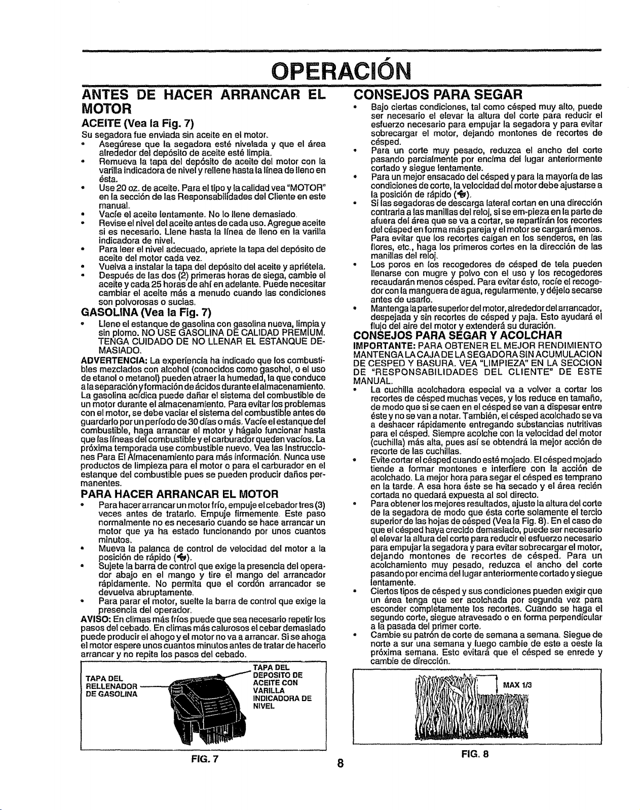
ANTES DE HACER ARRANCAR EL
MOTOR
ACEITE (Vea la Fig. 7)
Su segadora fue enviada sin aceite en el motor.
° Asegt3rese que la segadora est_ nivelada y que el drea
alrededor del dep6sRo de aceite est_ limpia.
o Remueva la tapa del dep6sito de aceite del motor con la
varilla indicadora de nivel y rellene hasta la lt'nea de lleno en
_sta.
. Use 20 oz. de aceite. Para el tipo y ta calidad vea "MOTOR"
en ia secci6n de las Responsablhdades del Cliente en este
manual.,
* Vacfe el aceite lentamente. No Io llene demasiadQ
= Revise el nivet del aceite antes de cada uso. Agregue aceite
si es necesafio. Llene hasta la Ifnea de Ileno en la varilla
indicadora de nivel.
= Para leer e! nivel adecuado, apriete la tapa del dep6sito de
aceite del motor cada vez.
. Vuelva a instalar la tapa del dep6sito del aceite y apri(_tela.
= Despu_s de las dos (2) primeras horas de siega, cambie el
aceite y cada 25 horas de ahf en adelante. Puede necesitar
cambiar el acelte m_s a menudo cuando las condiciones
son polvorosas o sucias.>
GASOLINA (Vea la Fig. 7)
o Llene el estanque de gasolina con gasolina nueva, limpia y
sin plomo. NO USE GASOLtNA DE CAL1DAD PREMIUM.
TENGA CUIDADO DE NO LLENAR EL ESTANQUE DE-
MASIADO.,
ADVERTENCIA: La experiencia ha indicado que los combusti-
bles mezclados con alcohol (conocidos como gasohot, o e! uso
de etanol o metanol) pueden atraer ia humedad, taque conduce
ala separaci6ny formaci6n de _cidos duranteel almacenamiento.
La gasolina acfdica puede dafiar el sistema del combustible de
un motor durante el almacenamiento. Para evitar los probtemas
con el motor, se debe vaciat el sistema del combustibleantes de
,iv
i
......CONSEJOS PARA SEGAR
° Bajo ciedas condiciones, tal como cdsped muy alto, puede
ser necesario el elevar la altura del code para reducir el
esfuerzo necesario para empujar la segadora y para evitar
sobrecargar el motor, dejando montones de recortes de
cdsped.
• Para un code muy pesado, reduzca el ancho del corte
pasando parcialmente por enclma del lugar anteriormente
codado y siegue {entamente.
• Para un mejor ensacado del c6sped y para la mayorl'a de ias
condicionesde corte, lavelocidad del motor debe ajustarse a
la posid6n de r_pido (,_),.
= Si tas segadoras de descarga lateral cortan en una direcci6n
contrada a las maniUasdel reloj,si se em-pieza en la parle de
afuera def drea que se va a codar, se repadir_n los recortes
del c_sped en forma m_s pareja y el motor se cargar_ menos.
Para evitar que los recodes caigan en los senderos, en {as
flores, etc., haga los primeros codes en la direcci6n de las
manillas del reloj.
• Los poros en los recogedores de c_sped de tela pueden
Ilenarse con mugre y polvo con el uso y los recogedores
recaudar_n menos cesped. Para evitar _sto, rocl'eet recoge-
dot con la manguera de agua, regularmente, y d_jelo secarse
antes de usarlo.
° Mantenga laparle superior del motor, alrededordel ar_ancador,
despejada y sin recortes de c_sped y paja. Esto ayudar& el
flujo del aire del motor y extender_ su duraci6n_
CONSEJOS PARA SEGAR Y ACOLCHAR
IMPORTANTE: PARA OBTENER EL MEJOR REND1MIENTO
MANTENGA LA CAJA DE LA SEGADORA SIN ACUMULAClON
DE CESPED Y BASURA. VEA "LIMPIEZA" EN LA SECClON
DE "RESPONSABILIDADES DEL CLIENTE" DE ESTE
MANUAL.
guardado pot un pe ri'odode 30 d/as o m_s, Vacfe el estanque del
combustible, haga arrancar el motor y h&galo funcionar hasta
que las Ifneas del combustible y el carburador queden vacfos, La
pr6xima temporada use combustible nuevo, Vea las Instruccto-
nes Para EI Nmacenamiento para m_s informaci6n_Nunca use
productos de limpieza para el motor o para el carburador en el
estanque del combustible pues se pueden producir dafios per_
manentes.
PARA HACER ARRANCAR EL MOTOR
• Para hacer arrancar un motor fri'o, empuje el cebador ires (3)
veces antes de tratarlo. Empuje firmemente. Este paso
normalmente no es necesario cuando se hace arrancar un
motor que ya ha estado funcienando pot unos cuantos
minutos_
• Mueva ta palanca de control de velocidad del motor a la
posici6n de r_pido ('_).
° Sujete la barra de controlque exige ta presencia del opera-
dor abajo en el mango y tire el mango del arrancador
r8pidamente. No permRa que el cerd6n arrancador se
devuelva abruptamente.
° Para parar el motor, suelte la barra de control que exige la
presencia del operador_
AVISO: En climas m_s frfos puede que sea necesario repetir los
pasos del cebadoo En ctimas m_s calurosos el cebar demaslado
puede producir el ahogo y el motor no va a arrancar. Si se ahoga
el motor espere unos cuantos minutos antes de tratar de hacerlo
arrancar y no repita los pasos det cebado.
TAPA DEL
TAPA DEL
RELLENADOR _ ACEITE CON
DE GASOLINA VARILLA
tNDICADORA DE
NIVEL
• La cuchtlla acolchadora especial va a volver a cortar los
recortes de cdsped muchas veces, y los reduce en tamafio,
de modo que si se caen en et cdsped se van a dtspesar entre
(_stey no se van a notar. Tambi_n et c_sped acolchado se va
a deshacer r_ptdamente entregando substancias nutdtivas
para el c_sped. Siempre acolche con la velocidad del motor
(cuchilla) rods alta, pues asi' se obtendr_ la mejor acci6n de
recorte de las cuchillas°
° Evite cortar el c_isped cuando est_ moiado.. El c6sped mojado
tiende a formar montones e interfiere con la acci6n de
acolchado. La mejor hofa para segar el c_sped es temprano
en la tarde, A esa hora _ste se ha secado y el &rea reci_n
cortada no quedard expuesta al sol directo.
° Para obtener los mejores resultados, ajusle la aRura del corte
de la segadora de modo ClUe_sta corte solamente el tercio
superior de las hojas de cdsped (Vea la Fig. 8).. En et caso de
que el c_sped haya crecido demasiado, puede set necesario
el elevar la altura del corte para reducir el esfuerzo necesario
dParaempujar la segadora y para evitar sobrecargar el motor,
ejando montones de recortes de c_sped. Para un
acolchamiento muy pesado, reduzca el ancho del corte
asando pot encima del lugar anteriormente cortado ysiegue
ntamente_
,, Ciertos tipos de c_sped y sus condiciones pueden exigir que
un &tea tenga que ser acolchada pot segunda vez para
esconder completamente los recortes. Cuando se haga el
segundo code, siegue atravesado o en forma perpendicular
a la pasada del primer corte_
= Cambie su patr6n de corte de semana a semana, Siegue de
norte a sur una semana y fuego cambie de este a oeste la
pr6xima semana, Estc evitar_ que el c_sped se enrede y
cambie de dlrecci6n.,
MAX 113
FIG, 8
FIG. 7 8
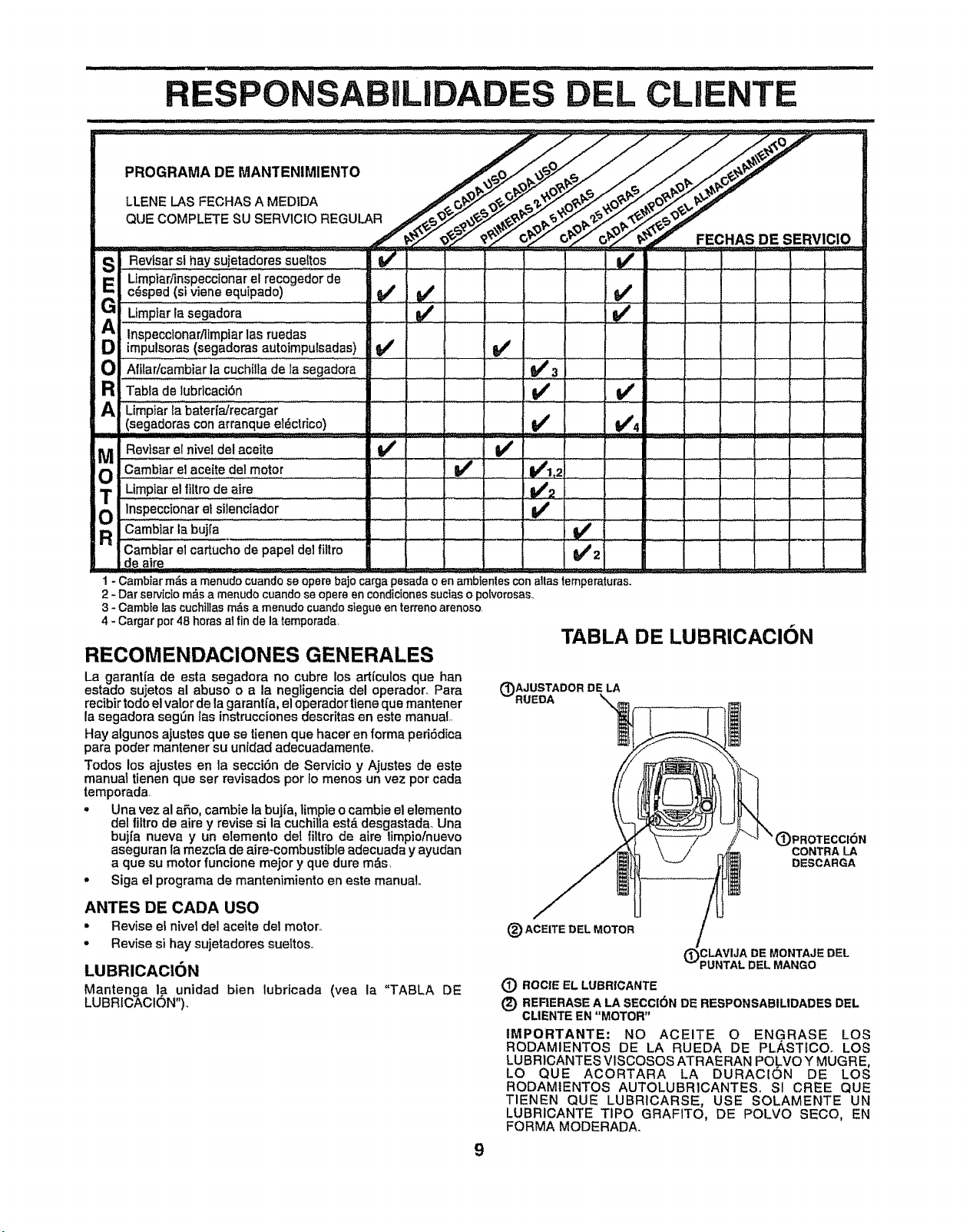
ABILI D L CL NTE
/_1_y FECHAS DE SERVICtO
SI_, Revisar si hay sujetadores sueltos
Umpiadinspeccionar el recogedor de
_! c_sped (si viene equipado)
G UmPi_ria;_gad0ia
lnsP'e'ccionarilimpiar ias rueclas
impulsoras (segadoras autoimpursadas)
Ol Affiaricambiar la cuchilta de la segadora
a Tabla de lubdcaci6n
A Limp_arlabateri_reCargar .................
(segadoras con arranque e!_ctrico)
MOReviseret,iVeldelaooite .............v"_ambiar el acette del m0t0r .... .i i J J
Limpiare! flltrode airs I J I J
('_ inspecc{0nareI silenctador ........
R CBmbiariabuiia .......
..... If ......
ii i L IIIIIIIIII-
Camb[ar el cartucho de papel del filtro
de Mire
.V'3
v'
V' v'4
.,,,,,,
I - Cambiar m&s a menudo cuando se opera bajo carga pesada o en ambtenles con alias ternperaturas.
2 - Dar servicfo m_s a menudo cuando se opere en cond[ciones suctas o potvorosas.,
3 - Carnbte las cuchIl[as rn_s a rnenudo cuando stegue en terreno arenoso.
4 - Cargar por 48 horas al fin de la temporada,
TABLA DE LUBRICACION
(_)AJUSTADOR DE LA
RUEDA
RECOMENDAClONES GENERALES
La garantfa de esta segadora no cubre los artfculos que han
estado sujetos al abuso o a la negligencia del operador,_ Para
recibir todoel valor de la garantfa, el operador tiene que mantener
la segadora seg0,n las instrucciones descritas en este manual,.
Hay algunos ajustes que se tienen que hacer en forms peri6dica
pars poder mantener su untdad adecuadamente,,
Todos los ajustes en la secci6n de Servicio y Aiustes de este
manual tienen que set revisados pot Io menos un vez por eada
temporada
• Una vez al afio, cambie la bujfa, limpte o eambie el elemento
del filtro de aire y revise si la cuchilia estd desgastada,,Una
buj_a nueva y un elemento del _tro de aim limpio/nuevo
aseguran la mezcfa de Mire-combustible adecuada y ayudan
a que su motor funcione mejor y que dure m,_s,
• Siga el programs de mantenimiento en este manual,,
(_)PROTECCION
CONTRALA
DESCARGA
ANTES DE CADA USO
° Revise el hive1 del aceite del motor°
• Revise si hay sujetadores sueitoso
LUBRICAOION
Mantenga la unidad bien lubricada (vea la "TABLA DE
LUBRICAClON'),
(_) ACEITE DEL MOTOR
MONTAJE DEL
PUNTAL DEL MANGO
(_) ROCIE EL LUBRiCANTE
(_) REFIERASE A LA SECCiON DE RESPONSABILIDADES DEL
CLIENTE EN "MOTOR"
tMPORTANTE: NO ACEITE O ENGRASE LOS
RODAMIENTOS DE LA RUEDA DE PLAST[COo LOS
LU BRICANTES VISCOSOS ATRAERAN POLVO Y MUGRE,
LO QUE ACORTARA LA DURAC[(_)N DE LOS
RODAMtENTOS AUTOLUBRICANTES, SI CREE QUE
TIENEN QUE LUBRICARSE, USE SOLAMENTE UN
LUBRICANTE TIPO GRAFITO, DE POLVO SECO, EN
FORMA MODERADA.
9
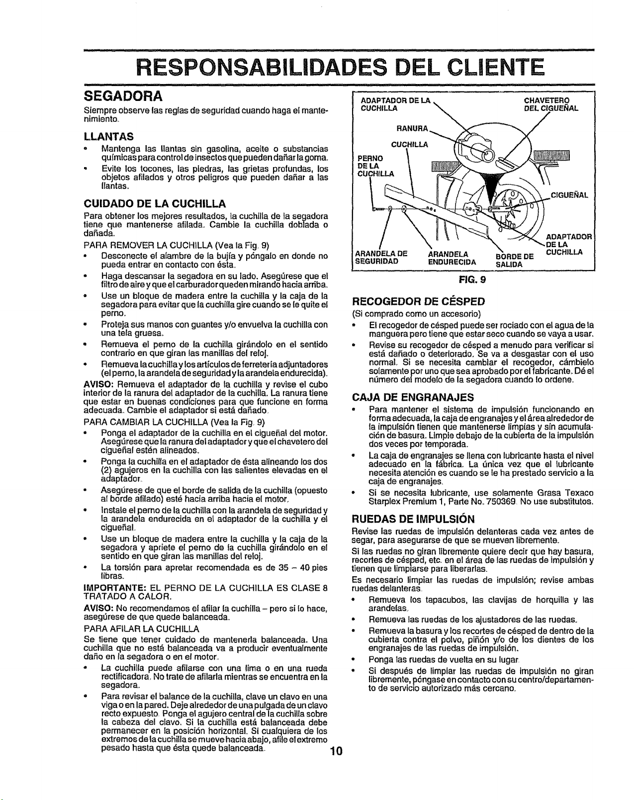
ILIDA L CLI NTE
SEGADORA
Siempre observe los reglas de seguridad cuando haga et mante-
nimlento
LLANTAS
o Mantenga los I]antas sin gasofina, aceite o substancias
qufmicas paracontrol deinsectes que pueden dafter la goma_
,, Evite los tocones, fas piedras, los grietas profundas, los
objetos afitados y otros peligros que pueden daSar a tas
llantaso
CUIDADO DE LA CUCHILLA
Para obtener los mejores resuitados, ta cuchflla de la segadora
tiene que mantenerse afilada. Cambie la cuchitla doblada o
daSada_
PARA REMOVER LA CUCH1LLA (Vea la Fig 9)
* Desconecte el afambre de la bujfa y pdngalo en deride no
pueda entrar en eontacto con _sta_
° Haga descansar la segadora en su lade. Aseg_rese que el
filtrode aire y que el carburador queden mirando hacia ardba.
o Use un bloque de madera entre la cuchilia y la caja de la
segadora para evitar que la cuchi[la gire cuando se[e quite el
perno_
- Proteja sus manes con guantes y!o envuelva la cuchtlla con
una tela gruesao
. Remueva el perno de Ia cuchilla girdndolo en el sentido
contrario en que giran los manillas del re[o].
o Remueva la cuehilla y los artfeulos de ferretet ia adjuntadores
(el perno, la arandela de seguridad y laarandela endurecida),
AVISO: Remueva el adaptador de la cuchflla y revise el cube
interior de la ranura del adaptador de la cuchifla. La ranura tiene
que ester en buenas condiciones para que funciene en forma
adecuada. Cambie el adaptador si est_ dafiado,
PARA CAMBIAR LA CUCHILLA (Vea la Fig. 9)
. Ponga el adaptador de la cuchilla en et cigueSal del motor.
Asegt3rese que la ranura del adaptador yque el chavetero del
ciguefial estdn alineados.
o Ponga la cuchilfa en el adaptador de _sta altneando los dos
(2) agujeros en la cuchilla con los salientes elevadas en el
adaptador.
. Asegerese de que el borde de saltda de la cuchilla (opuesto
at borde afilado) est6 hacia arriba hacia e! motor.
o Instaie el pemo de la cuehflla con la arandela de seguddad y
la arandela endurecida en et adaptador de la cuchilla y e|
ctgueSal.
° Use un bloque de madera entre la cuchilla y la caja de la
segadora y apriete el perno de la cuchilla girdndo[o en el
sentido en que 9|ran las manitlas del reloj,
° La torsidn para apreta_ recomendada es de 35 - 40 pies
libras_
IMPORTANTE: EL PERNO DE LA CUCHILLA ES CLASE 8
TRATADO A CALOR.
AVISO: No recomendames el afilar la cuchilla- pore si [o hace,
asegdrese de que quede balanceada.
PARA AFILAR LA CUCHILLA
Se tiene que tenor cuidado de mantenerla balanceada. Una
cuchilla que no estd balanceada va a producir eventualmente
da_o en la segadora o en el motor.
o La cuchilla puede afflarse con una lima o en una rueda
rectificadora, No trate de afilarla mienhas se encuentra an la
segadora.
° Para reviser el balance de la cuchil]a, clave un clave en una
viga o en la pared. Deje alrededor de una pulgada de un clave
recto expuesto Ponga el agujero central de la cuchilla sobre
la cabeza de! clave+ Si[a cuehilla estd balanceada debe
permanecer en la posiciSn horizontal. Si cua[quiera de los
extremes de |a cuchilla se mueve hacia abajo, afile el extreme
pesado hasta que dsta quede balanceada
ADAPTADOR DE LA . CHAVETERO
CUCHILLA _. DELClGUE_AL
RANURA _
CUCHILLA /'_ / \
\
ADAPTADOR
_X CUCHILLA
ARANDELA DE ARANDELA BORDE DE
SEGURIDAD ENDURECIDA SALIDA
FIG. 9
RECOGEDOR DE CESPED
(Si comprado come un accesorio)
,, El recogedor de c_sped puede set rociado con el ague de la
manguera pero tiene que ester seco cuando se vaya a usan
• Revise su recogedor de cdsped a menudo para verificar si
estd daSado o deteriotado, Se va a desgastar con et use
normal. Si se necesita cambiar el recogedor, cAmbieto
solamente per uno que sea aprobado per el fabricante. Dd el
ndmero delmodelo de la segadora cuando io ordene.
CAJA DE ENGRANAJES
• Para mantener el slstema de im.pulsidnfuncionando en
forma adecuada, la caja de engrana]es y el _rea alrededor de
{a impulsfdn tienen que mantenerse limpias y sin acumula-
ci6n de basura, LlmpJe debajo de la cubierta de la impulsi6n
dos veces per temporada.
• La caja de engranajes se llena con Lubrtcante hasta el nivel
adecuado en la fabricao La Qn[ca vez que el tubdeante
necesita atencidn es cuando se ie ha prestado servicio ala
caja de engranajes.
• Si se necesita lubr_cante, use solamente Grasa Texaco
Starplex Premium 1, Parle No. 750369 No use substitutes.
RUEDAS DE IMPULSION
Revise las ruedas de impulsidn delanteras cada vez antes de
segar, pare asegurarse de que se mueven libremente.
Si [as ruedas no giran |Ibremente quiere decir que hay basura,
recortes de cdsped, etc. en el;_reade las ruedas de lmpulsi6n y
tienen que limplarse para liberarlas.
Es necesario limp|at las ruedas de impulsi6n; revise ambas
ruedas delanteras
° Remueva los tapacubos, las clavijas de horquilla y las
arandelas
• Remueva las ruedas de los ajustadores de los ruedas.
• Remueva la basura y los recedes de cdsped de dentro de la
cubierta contra el polvo, pi55n yio de los dientes de los
engranajes de los ruedas de impulsi6n.
• Ponga las ruedas de vuelta en su lugar
. Si despuds de timpiar las ruedas de impuisidn no giran
libremente, pdngase en contacto con su centro/departamen-
to de servicio autodzado mds cercano,
10
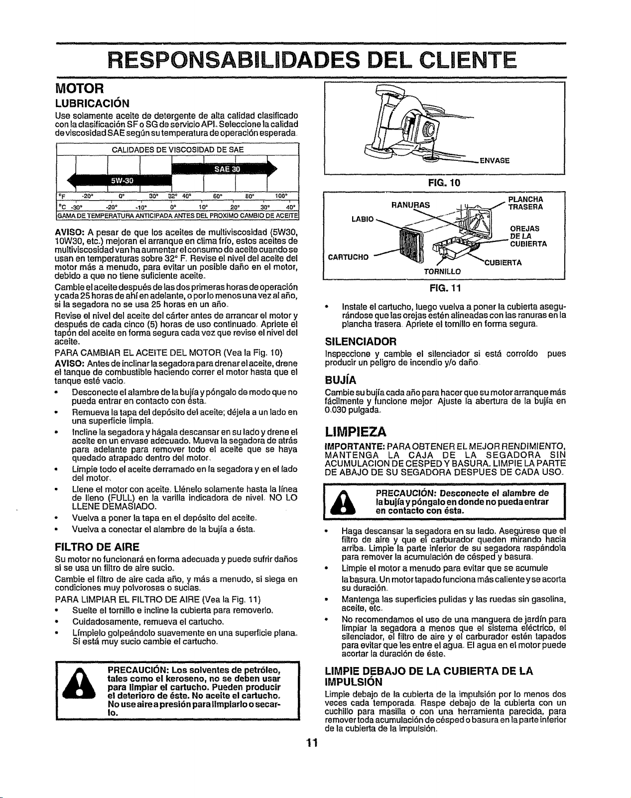
BiLl
MOTOR
LUBRICAClON
Use solamente aceite de detergente de alia calidad clasificado
con la clasificaci6n SF o SG de servicio APL Seleccione la calidad
deviscosidad SAE segt_n su temperatura de operaci6n esperada.
CALIDADES DE VISC0SIDADDE sAE
imm
_F "20 = O" 30" 02 ° 40= 60" B0" t00 °
°c -s0o -2'oo .1;. oo 4o° 20° 3o. 40"
0AMA DE TEMPERATURA ANTiciPADA ANTES DEL PROXIMO CAMBIO DE ACEITE
AVISO: A pesar de que los aceites de multiviscostdad (5W30,
10W30, etc.) mejoran e! arranque en ctima frfo, estos aceites de
multiviscosidad van ha aumentar el consume de aceite cuando se
usan en temperaturas sobre 32 ° F, Revise el nivel del aceite del
motor m6s a menudo, para evitar un posible dare en el motor,
debido a que no tiene suliciente aceite_
Cambie el aceite despu_s de las dos primeras horas de operaci6n
ycada 25 horas de ahf en adelante, o per Io menos una vez al are,
si la segadora no se usa 25 horas en un are.,
Revise el nivel del aceite del carter antes de arrancar el motor y
despu_s de cada cinco (5) horas de use conttnuado, Apriete el
tapon del aceite en forma segura cada vez que revise el nivel del
aceite.
PARA CAMBIAR EL ACEITE DEL MOTOR (Vea la Fig_ 10)
AVISO; Antes de inclinarla se_adora paradrenar el aceite, drene
et tanque de combustible hamendo cotter el motor hasta que el
tanque est_ vacio..
- Desconecte el alambre de la bujfa yp6ngalo de mode que no
pueda entrar en contacto con _sta..
• Remueva la tapa del dep6sito del aceite; d_jela a un lade en
una supefficie limpia..
= Incline la segadora y h&gala descansar en su lade y drene el
aceite en un envase adecuado. Mueva la segadora de atr&s
para adelante para remover todo el aceite que se haya
quedado atrapado dentro del motor,,
• Limpie todo el aceite derramado en la segadora yen el fade
del motor,
• Llene el motor con aceite_ Ll_nelo solamente hasta la lfnea
de Ileno (FULL) en la vadlla indicadora de niveL NO LO
LLENE DEMASIADO.
° Vuelva a porter ta tapa en el dep6stto del aceite,,
• Vuelva a conectar el alambre de la bujfa a 6sta.
FILTRO DE AIRE
Su motor no funcionar_ en forma adecuada y puede sufdr dafios
si se usa un _tro de aire sucio,,
Cambie el filtro de aire cada aSe, ,ym_s a menudo, si siega en
condiciones muy potvorosas o suc=as,,
PARA LIMPIAR EL FILTRO DE AIRE (Yea la Fig,.11)
° Suelte el torniilo e incline la cubierta para removerloo
° Cuidadosamente, remueva el cartucho.,
- Lfmpielo golpe_,ndolo suavemente en una superlicie plana,,
Si est_ muy sucio cambie el cartucho.,
PRECAUCI6N: Los soiventes de petr61eo,
tales come el kerosene, no se deben usar
para limpiar el cartucho, Pueden producir
el deterioro de _ste. No acelte el cartuchoo
No use aire a presi6n para Ilmpiarlo o secar-
|O_ H ,,,i ii, m
DEL CLIENTE
11
FIG. 10
_I_ -j'_'° _,..V-E-...._I1 OREJAS
IINB_Jl_tl}) _ DE LA
CARTUCHO _ "_ ,_ _'_'CUBIERTA
TORNILLO
FIG. 11
° Instale el cartucho, iuego vuelva a poner la cubierta asegu-
rdndose que tas orejas estdn alineadas con ias ranuras en la
piancha trasera, Apriete el tomillo en forma segura,.
SILENCIADOR
tnspeccione y cambie el silenciador si est_ corro{do pues
producir un peligro de incendio y/o daSo
BUJiA
Cambie su buj(a cada a_o para hacer cfuesu motor arranque m_s
fdcilmente y funcione meier Ajuste ia abertura de la buj_a en
0,030 pulgada,,
LIMPIEZA
IMPORTANTE: PARA OBTENER EL MEJOR RENDIMIENTO,
MANTENGA LA CAJA DE LA SEGADORA SIN
ACUMULACION DE CESPED Y BASURA. LIMPIE LA PARTE
DE ABAJO DE SU SEGADORA DESPUES DE CADA use,,
i _ iii i ,, i iiJ i,l,J,.., i i ,lll,l,i ill
........ PRECAUCION: Desconecte el alambre de !
&
labujfa y p6ngalo en deride no pueda entrar |
en contacto con _sta. !
• Haga descansar la segadora en su lade. Asegt)rese ClUeel
filtro de aire y que el carburador queden mirandohacia
ardba,, Limpie la parte inferior de su segadora rasp_ndola
para remover la acumulaci6n de c6sped y basura,
° Limpie el motor a menudo para evitar que se acumule
la basura,, Un motor tapado funciona m&s caliente y se acorta
su duraci6n.,
• Mantenga las superficies pulidas y las ruedas sin gasolina,
acelle, etc,,
• No recomendamos el use de una manguera de jard{n para
limpiar la segadora a menos que e! sistema el_ctrico, el
silenciador, el filtro de aire y el carburador esl_n tapados
para evitar que les entre el agua., El agua en el motor puede
acortar la duraci6n de este.
LIMPIE DEBAJO DE LA CUBIERTA DE LA
IMPULSION
Limpie debajo de la cubterta de la impulsi6n per 1o menos dos
veces cada temporada, Raspe debajo de la cubierta con un
cuchillo para masilla o con una herramienta parecida, para
remover toda acumulaci6n de cesped o basura en la parte inferior
de la cubierta de la impulsibno
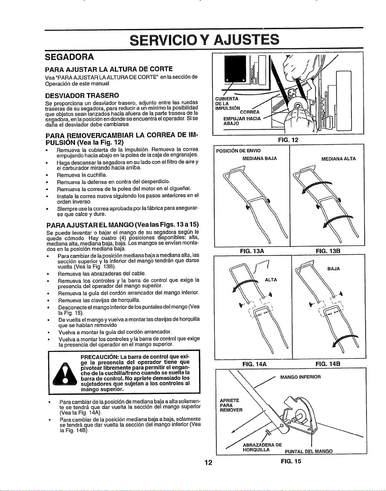
...................................... , ,, ..... illlll,ll,lll,ll
SEGADORA
PARA AJUSTAR LA ALTURA DE CORTE
Vea"PARA AJUSTAR LA ALTU RA DE CORTE" en lasecci6n de
Operaci6n de este manual
DESVIADOR TRASERO
Se proporciona un desviador trasero, adjunto entre Ias ruedas
traseras de su segadora, para reducir a un mfnimo la posibilidad
que objetos sean lanzados hacia afuera de la parte trasera de la
segadora, en la posici6n en donde so encuentra el operador.. Si se
dafia el desviador debe cambiarse,
PARA REMOVER/CAMBIAR LA CORREA DE IM-
PULSION (Yea la Fig. 12)
- Remueva la cubierta de la impulsi6n_ Remueva la correa
empujando hacia abajo en ta polea de la caja de engranajes..
° Haga descansar Ia segadora en su lado con el filtro de aire y
e] carburador mirando hacia arfiba.
= Remueva la cuchilia.
• Remueva la defensa en contra del desperdicio..
• Remueva la correa de la polea del motor en et ciguefiaL
° Instals la correa nueva siguiendo los pasos anteriores en el
orden inverso.
- Siempre use la correa aprobada pot la f_brica para asegurar-
se que calce y dure.
PARA AJ USTAR EL MANGO (Vea las Figs. 13 a 15)
Se puede levantar o bajar el mango de su segadora seg_n le
quede c6modo Hay cuatro (4) posiciones disponibles: alta,
mediana alta, mediana baja, baja. Los mangos se envfan monta-
dos en la posici6n mediana baja.
• Para cambiar de la posici6n mediana baja a mediana alta, tas
secci6n superior y la inferior del mango tendrdn que darse
vuelta (Vea la Fig 13B)
• Remueva las abrazaderas del cable,
• Remueva los controlesy la barra de control que exige la
presencia del operador det mango superior.
• Remueva la gufa del cord6n arrancador del mango inferior.
• Remueva las clavijas de horquilla..
• Desconecte el mango inferiorde los puntales del mango (Vea
la Fig. 15)..
• De vuelta el mango y vuetva a montar las clavijas de horquilla
que se habfan removido.
• Vuelva a montar la guta del cordSn arrancador_
° Vuelva a montar los controles y la barra de control que exige
la presencia del operador en el mango superior.
u
PRECAUCION: La barra de control que exi- /
_ge la presencia del operador ttene que
1
pivotear libremente para permitir el engan-
che de la cuchilla/freno cuando se suetta la
barra de control. No apriete demasiado los
sujetadores que suJetan a los controles al
mango supermr. ....................................
* Para cambiar de la posic|6n de mediana baja a alta solamem
te se tendr,_ que dar vuelta la secci6n def mango superior
(Yea la Fig. I4A).
- Para cambiar de ta posicibn mediana baja a baja, solamente
se tendr_, que dar vuelta la secci6n del mango inferior (Vea
la Fig. 14B).
CUEtlERTA
DE LA
IMPULSION
CORREA
EMPUJAR HACIA
ABAJO
FIG. 12
POSICtON DE ENVIO
MEDIANA BAJA
FIG. 13A
MEDIANA ALTA
FIG. 13B
ALTA
\
\
BAJA
FIG. 14A FIG. 14B
MANGO INFERIOR
APRIETE
PARA
REMOVER
ABRAZADERA DE
HORQUILLA PUNTALDEL MANGO
12 FIG. 15
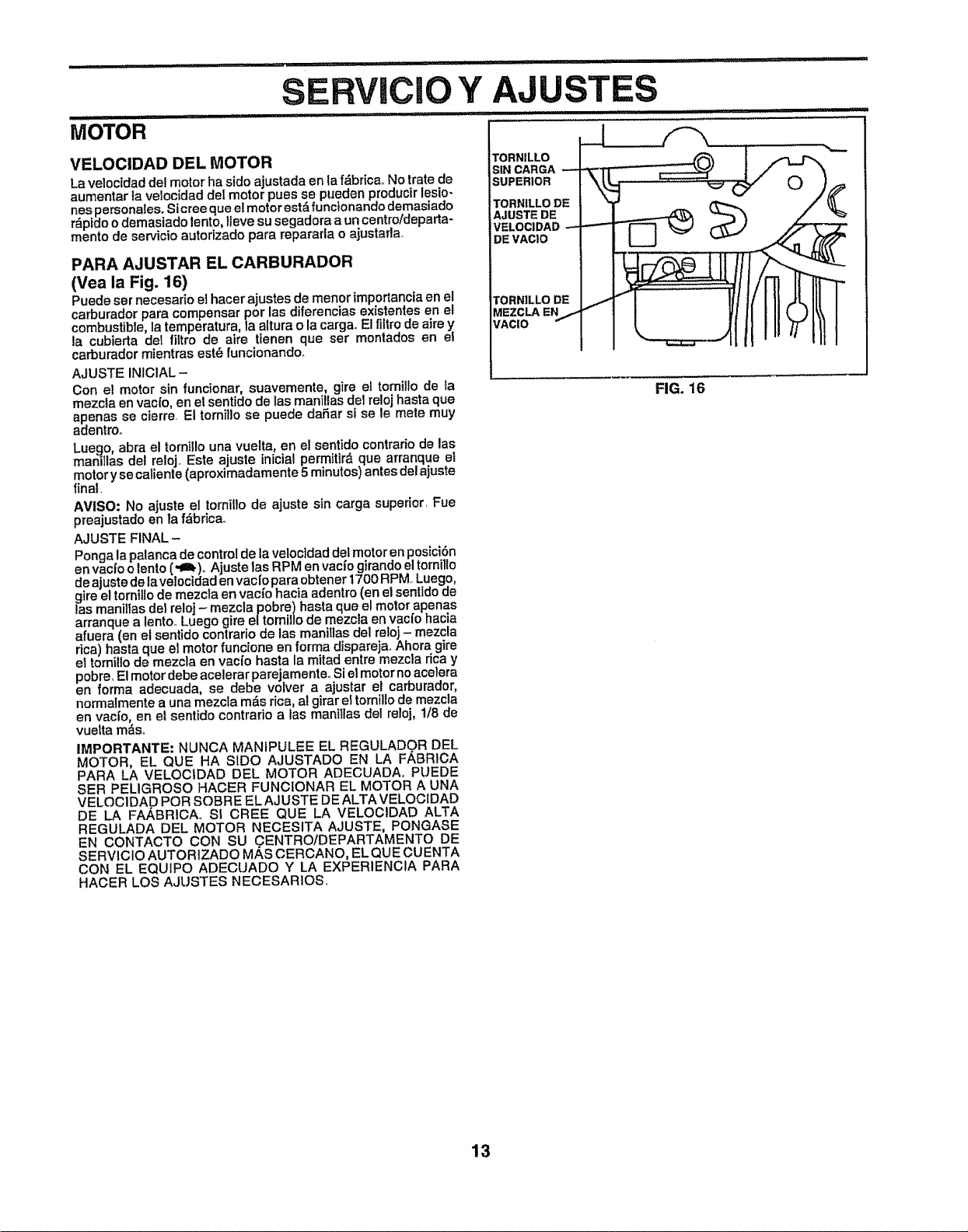
VELOCIDAD DEL MOTOR
La velocidad del motor ha sido ajustada en la f_brica_.No trate de
aumentar la velocidad deI motor pues se pueden producir lesio-
nes personales. St cree que el motor est& funcionando demasiado
r_pido o demasiado lento, Iteve su segadora a un centro/departa-
mento de servicio autorizado para repararla o ajustarla.
PARA AJUSTAR EL CARBURADOR
(Yea la Fig. 16)
Puede ser necesario el hacer ajustes de menor importancia en el
carburador para compensar por las diferencias ex_stentesen el
combustible, la temperatura, la aEturao la carga_ El filtro de aim y
la cubierta del _tro de atre tienen que ser montados en e!
carburador mientras estd funcionando_
AJUSTE INICIAL-
Con el motor sin funcionar, suavemente, gire el tornillo de la
mezcla en vac{o, en el sentido de tas manillas de1reloj hasta que
apenas se cierre. El tomillo se puede da_ar si se le mete muy
adentroo
Luego, abra el torn{{Iouna vuelta, en el sentido contrario de las
manitlas del reloj., Este ajuste lnicial perrnitir_ que arranque el
motor y se calJenle (aproximadamente 5 minutos) antes del ajuste
final.
AVISO: No ajuste el tomillo de ajuste sin carga superior. Fue
preajustado en la fdbrica.
AJUSTE FINAL -
Ponga la palanca de controlde la velocidad dal motor en posici6n
en vacJoo lento (-m.),, Ajuste las RPM en vac[o girando el tornillo
de ajuste de lavelocidad envaclo para obtener t700 RPM Luego,
gire el tornillo de mezcla en vac{o hacia adentro (en el senttdo de
las manillas de! reloj- mezcla pobre) hasta que el motor apenas
arranque a lento° Luego gire el tomil!o de mezcla en vac{o hacia
afuera (en el sentido contrario de las manillas del reloj - mezcla
rica) hasta que el motor funcione en forma dispareja. Ahora gire
el tornillo de mezcla en vaci'o hasta la mitad entre mezcla dca y
pobre, El motordebe acelerar parejamenteo Si el motor no acelera
en forma adecuada, se debe volver a ajustar el carburador,
normalmente a una mezcla rods rica, at girar e!tornil/o de mezcla
en vacfo, en et sentido contrario alas manillas del re!oj, t/8 de
vuelta mdso
IMPORTANTE: NUNCA MANIPULEE EL REGULADOR DEL
MOTOR, EL QUE HA SIDO AJUSTADO EN LA FABRICA
PARA LA VELOCtDAD DEL MOTOR ADIECUADA. PUEDE
SER PELIGROSO HACER FUNCfONAR EL MOTOR A UNA
VELOCIDAD POR SOBRE EL AJUSTE DE ALTA VELOCIDAD
DE LA FA,_BRICA. SI CREE QUE LA VELOCIDAD ALTA
REGULADA DEL MOTOR NECESITA AJUSTE, PONGASE
EN CONTACTO CON SU CENTRO!DEPARTAMENTO DE
SERVIClO AUTORIZADO MAS CERCANO, EL QUE CUENTA
CON EL EQUIPO ADECUADO Y LA EXPERIENClA PARA
HACER LO8 AJUSTES NECESARIOS.
TORNILLO
SIN CARGA
SUPERIOR
TORNILLO DE
AJUSTE DE
VELOCIDAD
DE VAClO
TORNILLO DE
MEZCLA EN
VACIO
FIG. 16
13
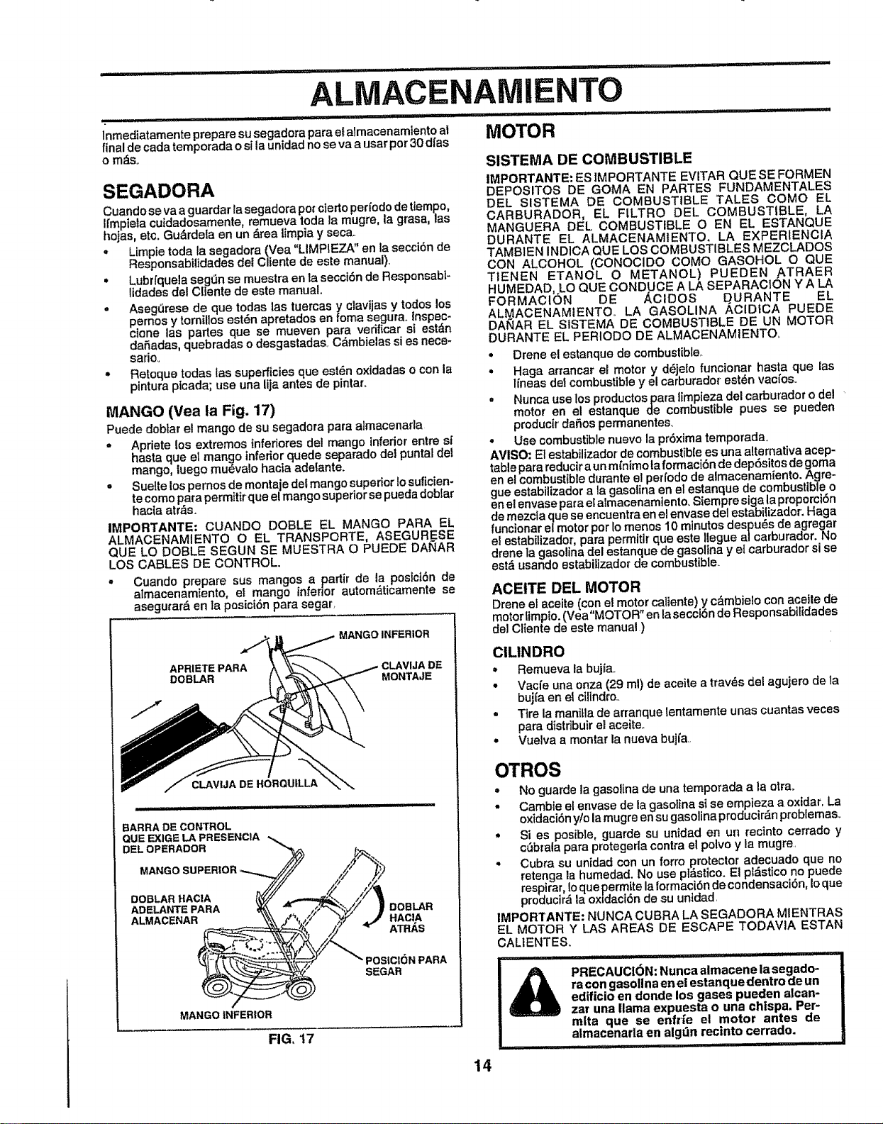
.............................. i i,
ALMACENAMIENTO
lllll ........................................ ..... ............................. .......
lnmediatamente prepare su segadora para el almacenamlento at MOTOR
final de cada temporada o si la unidad no se va a usar per 30 dt'as
o m_s.
SEGADORA
Cuando se va a guardar la segadora pot cleric per{ode de tiempo,
It'mpieta cuidadosamente, remueva toda la mugre, la grasa, las
hojas, etc.. Gu_rdela en un _rea limpia y seca.
• Limpie toda la segadora (Vea "LIMPIEZA" en la secci6n de
Responsabilidades del Cliente de este manual).
• Lubrfquela seg0n se muestra en la secci6n de Responsabl-
lidades del Cliente de este manual..
, AsegOrese de que todas las tuercas y ctavijas y todos los
pemos y tornillos est_n apretados en foma segura, inspec-
clone las partes que se mueven para vedficar si est&n
daSadas, quebradas o desgastadas. C_mbJelas si es nece-
sarioo
• Retoque todas las superficies que est_n oxidadas o con la
pintura plcada; use una lija antes de pintar..
MANGO (Yea la Fig. 17)
Puede dobtar el mango de su segadora para atmacenaria
* Apriete los extremes inferiores del mango inferior entre s{
hasta que el man_lO inferior quede separado de! puntaldel
mango, luego muevalo hacla adelante.
o Suelte los pemos de montaje det mango superior to suficien-
tecome para permitir que e/mango superior se pueda doblar
hacta atr,_s.
IMPORTANTE: CUANDO DOBLE EL MANGO PARA EL
ALMACENAMIENTO O EL TRANSPORTE, ASEGURESE
QUE LO DOBLE SEGUN SE MUESTRA O PUEDE DAI_AR
LOS CABLES DE CONTROL.
° Cuando prepare sus mangos a partir de la posici6n de
atmacenamiento, el mango inferior autom_ticamente se
asegurar_ en Japosici6n para segar.
MANGO INFERIOR
APRIETE PARA
DOBLAR MONTAJE
BARRA DE CONTROL
CLAV{JA DE HORQUtLLA
,_7/DOBLAR
, // ArRAs
"_/_ _" POSICION PARA
SEGAR
}
MANGO INFERIOR
FIG, 17
SISTEMA DE COMBUSTIBLE
IMPORTANTE: ES ]MPORTANTE EVITAR QUE SE FORMEN
DEPOSITOS DE GOMA EN PARTES FUNDAMENTALES
DEL SISTEMA DE COMBUSTIBLE TALES COMe EL
CARBURADOR, EL FILTRO DEL COMBUSTIBLE, LA
MANGUERA DEL COMBUSTIBLE O EN EL ESTANQUE
DURANTE EL ALMACENAMtENTO. LA EXPERIENCIA
TAMBIEN INDICA QUE LOS COMBUSTIBLES MEZCLADOS
CON ALCOHOL (CONOClDO COMe GASOHOL O QUE
TIENEN ETANOL O METANOL) PUEDEN ,ATRAER
HUMEDAD,.LO QUE CONDUCE A LA SEPARACION Y A LA
FORMACION DE /i,CIDOS QURANTE EL
ALM_ACENAMIENTO.. LA GASOLINA AClDiCA PUEDE
DANAR EL S1STEMA DE COMBUSTIBLE DE UN MOTOR
DURANTE EL PERIODO DE ALMACENAMIENTO.
• Drene el estanque de combustible..
• Haga arTancar el motor y d_jeio funcionar hasta que ias
l/heMS def combustibley el carburador est6n vac/os.
= Nunca use los productos para limpieza del carburador odel
motor en el eslanque de combuslible pues se pueden
producir daSos permanentes
, Use combustible nuevo la pr6xima temporada.
AVISO: E1estabilizador de combustible es una alternativa acep-
table para reducir a un m[nimo ta formaci6n de dep6sitos de goma
en el combustible durante el perfodo de almacenamiento. Agre-
gue estabilizador a la gasolina en el estanque de combustible o
en el envase para el almacenamiento. Siempre stgala proporci6n
de mezcla que se encuentra en el envase del estabilizador: Haga
funcionar el motor per Io menos 10 minutes despu6s de agregar
el estabilizador, para permitir que este Ilegue a/carburador. No
drene la gasolina del estanque de gasolina y el carburador si se
estd usando estabilizador de combustible
ACEITE DEL MOTOR
Drene el aceite (con el motor ca_iente) y c_mbielo con aceiie de
motor timpio. (Vea"MOTOR" en la secci6n de Responsabilidades
del Cliente de este manual )
CILINDRO
° Remueva la bujia_
• Vac{e una onza (29 ml) de aceite a trav_s del agujero de la
buj{a en el cilindro..
° Tire la manitla de ananque lentamente unas cuantas veces
para distribuir el aceite_
• Vuelva a montar la nueva bujfa,
OTROS
• No guarde la gasolina de una temporada a la otra,.
• Cambie el envase de la gasolina si se empieza a oxidar. La
oxidaci6n yio la mugre en su gasolina producir_n problemas_
• Si es posible, guarde su unidad en un rectnto cerrado y
c6brala para protegeria contra el polvo y la mugre.
• Cubra su unidad con un forro protector adecuado que no
retenga la humedad. No use pl_stico. El pl_stico no puede
respirar, Io que permite la formaci6n de condensaci6n, toque
producir_ la oxidaci6n de su unidad.
1MPORTANTE: NUNCA CUBRA LA SEGADORA M1ENTRAS
EL MOTOR Y LAS AREAS DE ESCAPE TODAVIA ESTAN
CALIENTES_
i'1 iiiii iiiiii ii , ii ii [i,i1,11,11 i1,11,11, ,',1111 iiiii ii iii, i,'11111
PRECAUCION: Nunca almacenela segado- !
ra con gasollna en el estanque dentro de un I
edific|o en donde los gases pueden alcan- I
zar una llama expuesta o una chispa. Per- i
m|ta que se enfr_e el motor antes de I
almacenarta en algt3n recinto cerrado. .........
14
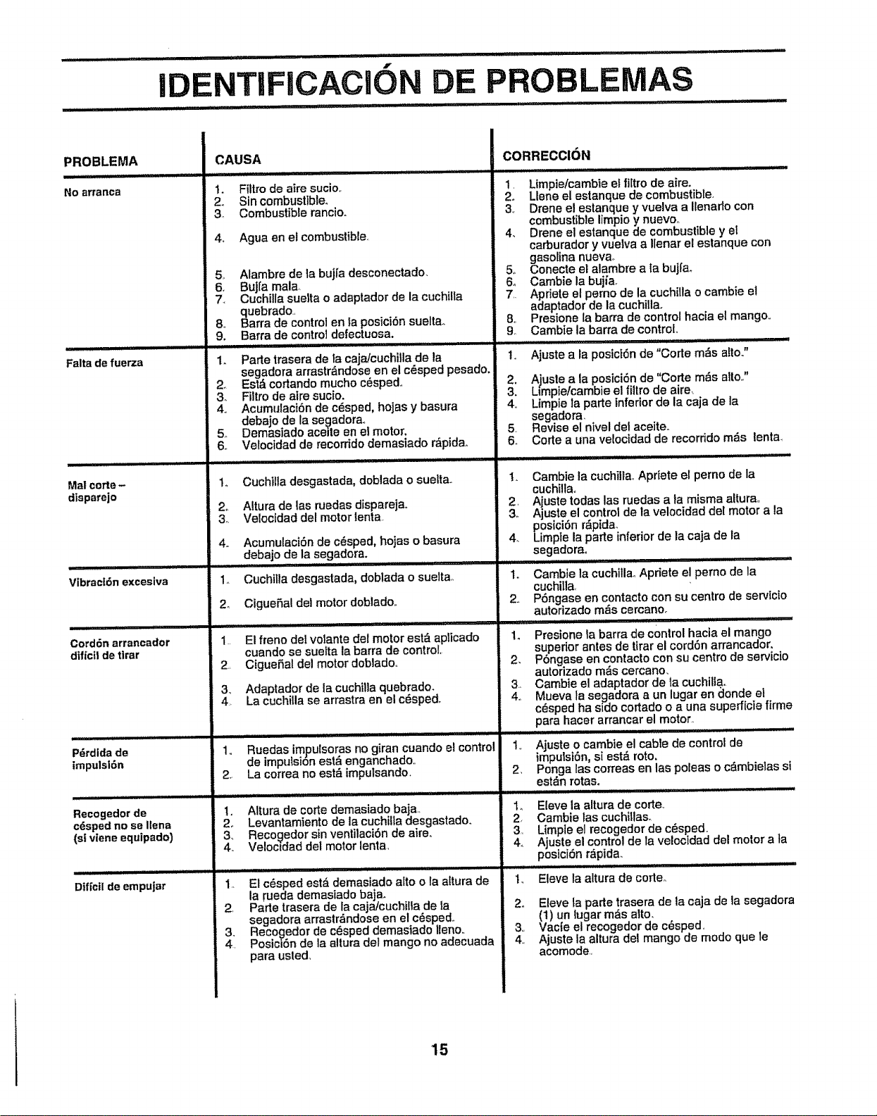
....... ii,
f
ENTIFICACION DE PROB
PROBLEMA
No arranca
Falta de fuerza
Mal corte-
dispareio
Vibract6n excesiva
......................... i_l,lll,
Cord6n arrancador
dlfi_cilde tirar
P_rdidade
irnpulsi6n
Recogedor de
cdsped no se liana
(s! viene equipado)
Hill Illl"lL/111/ II Ill
Dtfictl de empuiar
CAUSA
1. Filtro de aire sucio,.
2o Sin combusttble_
& Combustible rancio_
4o Agua en el combustible,
5, Alambre de la bujfa desconectado.
6. Bujfa mala,
7_ CuchiUa suelta o adaptador de la cuchilta
quebrado,,
8,, Barra de control en la posicion sueltao
9, Barra de control defectuosa.
1. Parte trasera de la caja/cuchilla de la
segadora arrastr_ndose en el cdsped pesado.
2. Est& cortando mucho cdsped.
3_ Filtro de alre sucio.
4. AcumulaciSn de c6sped, hojas y basura
debaje de la se_adorao
5o Demasiado ace_teen el motor.
6. Velocidad de recorrido demasiade r,ipida_
1o Cuchilla desgastada, doblada o suelta.
2. Altura de las ruedas dispareJao
3. Velocidad del motor lenta
4,, Acumulaci6n de c_sped, hojas o basura
debajo de la segadora.
1o Cuchitla desgastada0 doblada o suelta,,
2o Ciguefial del motor doblado,,
1,. El freno del volante del motor est,. aplicado
cuando se suefta la barra de control.
2. Ciguefial del motor doblado,,
Adaptador de la cuchilla quabrado_
La cuchilla se arrastra en el c_sped.
1,, Ruedas impulsoras no giran cuando el control
de impulsion est& enganchado,,
2., La correa no est_ imputsando,
1,, Altura de corte demasiado baja,
2,, Levantamiento de la cuchilla desgastado,
3_ Recogedor sin ventilaci6n de aire_
4., Velocldad del motor lenta,,
1,, El c_sped est_ demasiado alto o la altura de
la rueda demasiado baja_
2, Parle trasera de la cajaicuchilfa de la
segadora arrastr&ndose en el c_spedo
3. Reco_edor de c_sped demasiado Ileno..
4. Posicl6n de la altura del mango no adecuada
para usled,
CORRECCION
, Limpie/cambie el fi[tro de aim.
. Liana el estanque de combustibfe.
3, Drene el estanque y vuelva a Itenado con
combustible limpio y nuevo,,
4. Drene el estanque de combuslible y el
carburador y vuefva a Ilenar el estanque con
gasolina nuevao
5o Conecte el alambre a ta bujfao
6o Cambie la bujfa_
7,. Apriete et perno de la cuchilla o cambie el
adaptador de la cuchilla_
8,, Presione la barra de control hac{a el mango,,
9,, Cambie la barra de control,,
_
1., Ajuste a la posicf6n de "Corte m_s alto."
. Ajusle a la posiciSn de "Corte m_s alto,,"
Limpie/cambie el fillro de aire,
41 Limpie la parle tnferlorde la caja de la
segadora,
5. Revise el nivel del aceite_
6,, Corte a una velocidad de recorrido m_s lenta_
I. Cambie la cuchillaoApriete el perno de la
cuchillao
2, Aiuste todas las ruedas a la misma allura<,
3. Ajuste el control de ta velocidad del motor a la
pesicibn r_pida.,
4. Limpie la parte inferior de la caja de la
segadora.
1. Cambie la cuchilla_ Apriete el perno de la
cuchilla<
2, P6ngase en contacto con su centre de servicio
autorizado mEiScercano.
1o Presione la barra de control hacia el mango
superior antes de tirar el cord6n arrancador,
2, Pbngase en contacto con su centre de servicio
autorizado m&s cercano,
3. Cambte el adaptador de la cuchilla.
4o Mueva ta segadora a un lugar en _]onde et
c_sped ha side cortado o a una superftcie firme
para hacer arrancar el motor.
1_, Ajuste o cambte el cable de control de
impulst6n, si est& rote.
2, Ponga las correas en las poleas o cdmbielas si
est_n rotas.
1_ E{eve la altura de carte,
2, Cambie las cuchillas.
3, Limpte el recogedor de c_sped,
4, Ajuste el control de la veloctdad del motor a ta
postci6n r&pida_
1., Eleve la altura de corleo
2. Eleve la parle trasera de la caja de la segadora
(1) un lugar m&s alto.
3,, Vac{e el recogedor de c_sped,
4,, Ajuste la altura del mango de mode que le
acomode,,
15
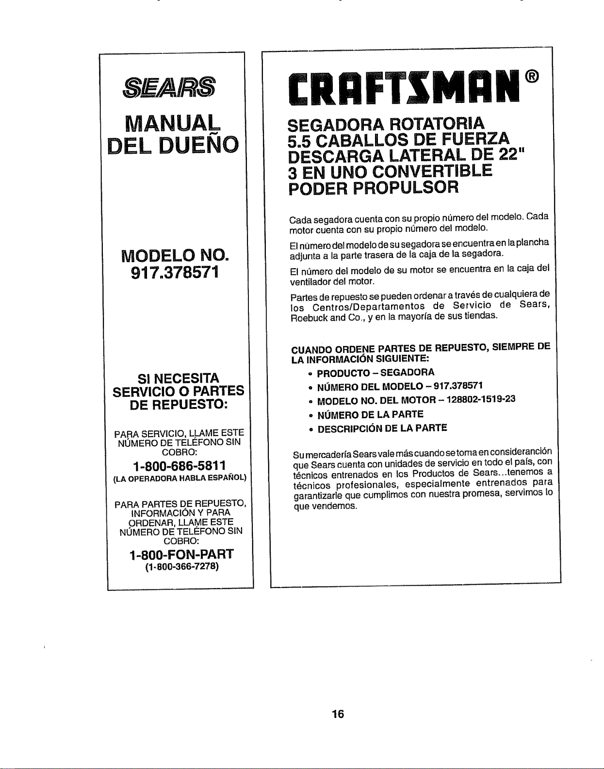
DEL
UAL
NO
MODELO NO.
917.378571
S! NECESITA
SERV!CIO O PARTES
DE REPUESTO:
PARA SERVICIO, LLAME ESTE
NOMERO DE TELI_FONO SIN
COBRO:
1-800-686-5811
(LA OPERADORA HABLA ESPA_IOL)
PARA PARTES DE REPUESTO,
INFORMACI6N Y PARA
ORDENAR, LLAME ESTE
NUMERO DE TELEFONO SIN
COBRO:
1-800-FON-PART
(1-800-366-7278)
CRnFTZMnN
SEGADORA ROTATORiA
5.5 CABALLOS DE FUERZA
DESCARGA LATERAL DE 22"
3 EN UNO CONVERTIBLE
PODER PROPULSOR
Cada segadora cuenta con su propio nemero del modelo. Cada
motor cuenta con su propio n0mero del modelo.
El nt_merodeI modelo de su segadora se encuentraen laplancha
adjunta a la parte trasera de la caja de la segadora.
El nl3mero del modelo de su motor se encuentra en la caja det
ventilador del motor.
Partes de repuesto se pueden ordenar a trav6s de cualquiera de
los Centros/Departamentos de Servicio de Sears,
Roebuck and Cm, yen la mayor/a de sus tiendas.
CUANDO ORDENE PARTES DE REPUESTO, SIEMPRE DE
LA INFORMACI(_N SIGUIENTE:
= PRODUCTO - SEGADORA
o NL_MERO DEL MODELO - 917.378571
° MODELO NO. DEL MOTOR - 128802-1519-23
° NUMERO DE LA PARTE
o DESCRIPCK_N DE LA PARTE
Su mercaderfa Sears vale m_s cuando se torna en consideranci6n
que Sears cuenta con unidades de servicio en todo el pat's,con
t6cnicos entrenados en los Productos de Sears..otenemos a
t6cnicos profesionales, especialmente entrenados para
garantizarle que cumplimos con nuestra promesa, servimos 1o
que vendemos.
16