Loading ...
Loading ...
Loading ...

PART 1: HOOD INSTALLATION GUIDE - INTEGRATED HOODS - ON BOARD MOTOR
ON BOARD HOOD
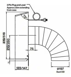
Models include SIENA F3SN60S1, F3SN90S1 and F3SND90S1
CONFIGURING HOOD FOR BACK DUCTED INSTALLATION
Note: Hood is delivered in with motor positioned for ducting through top of unit. To alter perform the following steps
STEP 1:
Remove external face plate covering back ducted hole by unscrewing at the two fixing points.
STEP 2:
Inside the hood locate the four fixing screws holding the motor and fixing plate to the top of the rangehood chasis. Remove the
screws and rotate the motor 90° backwards and push motor flange through exposed hole in back of the chassis.
STEP 3:
Re-secure the motor and fixing plate to the back of the chassis with the 4 screws removed in step 2. Finally secure the external
face plate removed in step 1 to the top of the rangehood and secure with at the two fixing points with the screws provided.
HOOD INSTALLATION
STEP 1:
To install into your overhead cupboard, several holes may need to be cut into shelves to enable the ducting to exit the cavity.
Ensure the hood is mounted as close to the centre of the cooking surface as possible.
NOTE:
The height of the underside of the hood body must be a minimum of 600 mm above an electric cooktop & 650 mm above a
gas cooktop and a maximum height of 1200 mm. If the instructions of the hob specify a greater distance than the minimum
detailed, this shall be the minimum height for installation. Building codes that stipulate a minimum dimension may vary from
state to state, please check with your local council prior to installation.
STEP 2:
If a shelf is fitted within the cupboard cut out a central 155mm hole in the shelf for ducting, matching the holes position to that of
the outlet on top of the hood. Additional holes might need to be cut to feed the duct out to the roof cavity.
STEP 3:
Remove the screws from within the main body of the rangehood along the back above the grease trap, on the left and right
side . Once the screws are removed, the main body of the rangehood will separate away from stainless steel fascia.
WARNING
DIMENSIONS ARE ACCURATE AT THE TIME OF PRINTING, PR KITCHEN & WASHROOM
SYSTEMS PTY LTD RESERVES THE RIGHT TO CHANGE SPECIFICATIONS WITHOUT NOTICE.
FOR BUILDING PURPOSES THE UNIT SHOULD BE PROVIDED TO THE CABINET MAKER /
BUILDER / KITCHEN DESIGNER FOR EXACT MEASUREMENTS.
Loading ...
Loading ...
Loading ...