Operator's Manual
(RRF¥$MRN°
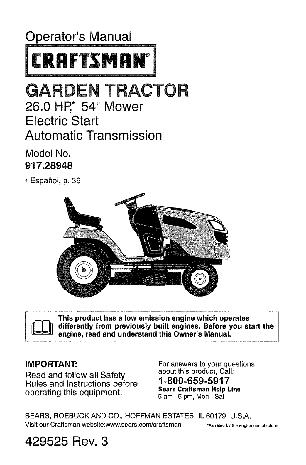
GAR
26.0 HP,* 54"
E0ectric Start
TRAOTO
Mower
Automatic Transmission
Model No.
917.28948
• EspaSoi, p. 36
This product has a low emission engine which operates
differently from previously built engines. Before you start the
engine, read and understand this Owner's Manual.
IMPORTANT:
Read and follow all Safety
Rules and Instructions before
operating this equipment.
For answers to your questions
about this product, Call:
1=800-659-5917
Sears Craftsman Help Line
5 am _ 5 pm, Mon - Sat
SEARS, ROEBUCK AND CO., HOFFMAN ESTATES, IL 60179 U.S.A.
Visit our Craftsman website:www.sears.com/craftsman *Ae rated by the engine manufacturer
429525 Rev. 3
Warranty .......................................................... 2
Safety Rules ............................................ 3
Product Specifications ............................. 6
AssemblyiPre-Operation ........................... 8
Operation ............................................... 13
Maintenance Schedule .......................... 21
Maintenance .......................................... 2t
Service and Adjustments ......................... 26
Storage .................................................. 31
Troubleshooting ...................................... 32
Sears Service ......................... Back Cover
Craftsman Riding Equipment Warranty:
Lawn Tractors, Garden Tractors, Zero Turn Riders
CRAFTSMAN TWO YEAR FULL WARRANTY
FOR TWO YEARS from the date of purchase, if any non-expendable part of this riding
equipment fails due to a defect in material or workmanship, visit www.craftsman.com or
call 1-800.659-5917 to arrange for free in-home repair.
The frame and front axle will be repaired free of charge for five years from the date of
purchase if defective in material or workmanship,
In all cases, if repair proves impossible, the riding equipment wil! be replaced free of
charge with the same or an equivalent model.
The battery wilt be replaced free of charge for 90 days from the date of purchase if
defective in material or workmanship (our testing proves that it will not hold a charge).
This warranty is void if this product is ever used while providing commercial services or if
rented to another person.
This warranty covers ONLY defects in material and workmanship. Warranty
coverage does NOT include:
° Expendable items that can wear out from normal use within the warranty period,
including but not limited to blades, spark plugs, air cleaners, belts, and oil filters.
° Standard maintenance servicing, oil changes, or tune-ups.
° Tire replacement or repair caused by punctures from outside objects, such as nails,
thorns, stumps, or glass.
° Tire or wheel replacement or repair resulting from normal wear, accident, or improper
operation or maintenance.
• Repairs necessary because of operator abuse, including but not limited to damage
caused by towing objects beyond the capability of the riding equipment, impacting
objects that bend the frame or crankshaft, or over-speeding the engine.
° Repairs necessary because of operator negligence, including but not limited to,
electrical and mechanical damage caused by improper storage, failure to use the
proper grade and amount of engine oil, failure to keep the deck clear of flammable
debris, or failure to maintain the riding equipment according to the instructions
contained in the operator's manual.
° Engine (fuel system) cleaning or repairs caused by fuel determined to be
contaminated or oxidized (stale). In general, fuel should be used within 30 days of its
purchase date.
• Normal deterioration and wear of the exterior finishes, or product label replacement°
This warranty gives you specific legal rights, and you may also have other rights which
vary from state to state.
Sears Brands Management Corporation, Hoffman Estates, IL 60179
_IbDANGER: This cutting machine is capable of amputating hands and feet and
throwing objects. Failure to observe the following safety instructions could result
in serious injury or death.
,_WARNING: In order to prevent acciden-
tal starting when setting up, transporting,
adjusting or making repairs, always discon-
nect spark plug wire and place wire where
it cannot contact spark plug.
_WARNING: Do not coast down a hill in
neutral, you may lose control of the tractor.
_WARNING: Tow only the attachments
that are recommended by and comply with
specifications of the manufacturer of your
tractor. Use common sense when towing.
Operate only at the lowest possible speed
when on a slope. Too heavy of a load, while
on a slope, is dangerous. Tires can lose
traction with the ground and cause you to
lose control of your tractor.
_WARNING: Engine exhaust, some of
its constituents, and certain vehicle compo-
nents contain or emit chemicals known to the
State of California to cause cancer and birth
defects or other reproductive harm.
_WARNING: Battery posts, terminals and
related accessories contain lead and lead
compounds, chemicals known to the State of
California to cause cancer and birth defects
or other reproductive harm. Wash hands
after handling.
I. GENERAL OPERATION
• Read, understand, and follow all instruc-
tions on the machine and in the manual
before starting.
, Do not put hands or feet near rotating
parts or under the machine. Keep clear
of the discharge opening at all times_
, Only allow responsible adults, who are
familiar with the instructions, to operate
the machine.
• Clear the area of objects such as rocks,
toys, wire, etc., which could be picked
up and thrown by the blades_
, Be sure the area is clear of bystanders
before operating° Stop machine ifanyone
enters the area.
• Never carry passengers.
• Do not mow in reverse unless absolutely
necessary. Always look down and behind
before and while backing.
° Never direct discharged material toward
anyone. Avoid discharging material
against a wall or obstruction. Material
may ricochet back toward the operator,
Stop the blades when crossing gravel
surfaces,
• Do not operate machine without the en-
tire grass catcher, discharge chute, or
other safety devices in place and working.
° Slow down before turning.
° Never leave a running machine unat-
tended. Always turn off blades, set
parking brake, stop engine, and remove
keys before dismounting.
• Disengage blades when not mowing.
Shut off engine and wait for all parts to
come to a complete stop before cleaning
the machine, removing the grass catcher,
or unclogging the discharge chute.
, Operate machine only in daylight orgood
artificial light,
° Do not operate the machine while under
the influence of alcohol or drugs.
• Watch for traffic when operating near or
crossing roadways.
o Use extra carewhen loadingorunloading
the machine into a trailer or truck.
° Always wear eye protectionwhen operat-
ing machine.
o Data indicates that operators, age 60
years and above, are involved ina large
percentage of riding mower-related inju-
ries. These operators should evaluate
their ability to operate the riding mower
safely enough to protectthemselves and
others from serious injury.
° Follow the manufacturer's recommen*
dation for wheel weights or counter-
weights.
, Keep machine free of grass, leaves or
other debris build-up whichcan touch hot
exhaust / engine parts and burn. Do not
allow the mower to plow leaves or other
debris which can cause build-up to oc-
cur. Clean any oil or fuel spillage before
operating or storing the machine. Allow
machine to cool before storage.
il. SLOPE OPERATION
Slopes are a major factor related to loss of
control and tip-over accidents, which can
result in severe injury or death° Operation
on all slopes requires extra caution° If you
cannot back up the slope orifyou feel uneasy
on it, do not mow it.
• Mow up and down slopes, not across.
• Watch for holes, ruts, bumps, rocks, or
other hidden objects. Uneven terrain
could overturn the machine. Tall grass
can hide obstacles.
, Choose a low ground speed so that you
will not have to stop or shift while on the
slope.
, Do not mow on wet grass. Tires may lose
traction.
Always keep the machine in gear when
going down slopes. Do not shift to neutral
and coast downhill.
, Avoid starting, stopping, or turning on a
slope, ifthetires Iosetraction, disengage
the blades and proceed slowly straight
down the slope.
, Keep all movement on the slopes slow
and gradual. Do not make sudden
changes in speed or direction, which
could cause the machine to roll over.
- Use extra care while operating machine
with grass catchers or other attachments;
they can affect the stability of the ma-
chine_ Do no use on steep slopes.
• Do not try to stabilize the machine by
putting your foot on the ground.
, Do not mow near drop-offs, ditches,
or embankments. The machine could
suddenly roll over if a wheel is over the
edge or if the edge caves in.
ill. CHILDREN
Tragic accidents can occur if the operator
is not alert to the presence of children.
Children are often attracted to the machine
and the mowing activity'. Never assume
that children will remain where you last
saw them.
• Keep children out of the mowing area
and in the watchful care of a responsible
adult other than the operator.
• Be alert and turn machine off if a child
enters the area.
• Before and while backing, look behind
and down for small children.
4
• Never carry children, even with the
blades shut off. They may fal! off and
be seriously injured or interfere with safe
machine operation. Children who have
been given rides in the past may suddenly
appear in the mowing area for another
ride and be run over or backed over by
the machine°
• Never allow children to operate the ma-
chine.
, Use extra care when approaching blind
corners, shrubs, trees, or other objects
that may block your view of a child.
IV. TOWING
° Tow only with a machine that has a hitch
designed for towing_ Do not attach towed
equipment except at the hitch point_
° Followthe manufacturer's recommenda-
tionfor weight limitsfor towed equipment
and towing on slopes,
• Never allow children or others in or on
towed equipment.
• On slopes, theweightofthetowed equip-
ment may cause lossof traction and loss
of control.
- Travel slowly and allow extra distance to
stop_
V. SERVICE
SAFE HANDLING OF GASOLINE
To avoid personal injury or property' dam-
age, use extreme care in handling gasoline.
Gasoline is extremely flammable and the
vapors are explosive.
• Extinguish all cigarettes, cigars, pipes,
and other sources of ignition.
• Use only approved gasoline container.
o Never remove gas cap or add fuel with
the engine running. Allow engine to cool
before refueling.
• Never fuel the machine indoors.
• Never store the machine or fuel container
where there is an open flame, spark, or
pilot light such as on a water heater or
other appliances.
• Never fill containers inside a vehicle or
on a truck or trailer bed with plastic liner.
Always place containers on the ground
away from your vehicle when filling.
° Remove gas-powered equipment from
the truck or trailer and refuel it on the
ground. If this is not possible, then refuel
such equipment with a portable container,
rather than from a gasoline dispenser
nozzle.
° Keepthe nozzlein contactwith the rim °
of thefuel tankor containeropeningat
alltimesuntilfuelingiscomplete.Do not
use a nozzlelock-opendevice.
tffuel isspilledonclothing,changecloth_
ing immediately_
Neveroverfillfueltank°Replacegascap
andtightensecurely.
o
e
GENERAL SERVICE
° Never operate machine in a closed
area.
• Keep all nuts and bolts tight to be sure the
equipment is in safe working condition,
• Nevertamperwith safety devices. Check
their proper operation regularly.
° Keep machine free of grass, leaves, or
other debris build-up. Clean oil or fuel
spillage and remove any fuel-soaked de-
bris. Allow machine to cool before storing.
°
o
If you strike a foreign object, stop and
inspectthe machine. Repair, if necessary,
before restarting.
Never make any adjustments or repairs
with the engine running.
Check grass catcher components and the
discharge chute frequently and replace
with manufacturer's recommended parts,
when necessary.
• Mower blades are sharp. Wrapthe blade
or wear gloves, and use extra caution
when servicing them.
° Check brake operation frequently. Adjust
and service as required,
• Maintain or replace safety and instruction
labels, as necessary_
° Be sure the area is clear of bystanders
before operating. Stop machine ifanyone
enters the area.
° Never carry passengers.
, Do not mow in reverse unless absolutely
necessary. Always took down and behind
before and while backing.
, Never carry children, even with the
blades shut off. They may fall off and
be seriously injured or interfere with safe
machine operation, Children who have
been given rides in the past may suddenly
appear in the mowing area for another
ride and be run over or backed over by
the machine.
• Keep children out of the mowing area
and in the watchful care of a responsible
adult other than the operator.
° Be alert and turn machine off if a child
enters the area.
° Before and while backing, look behind
and down for small children.
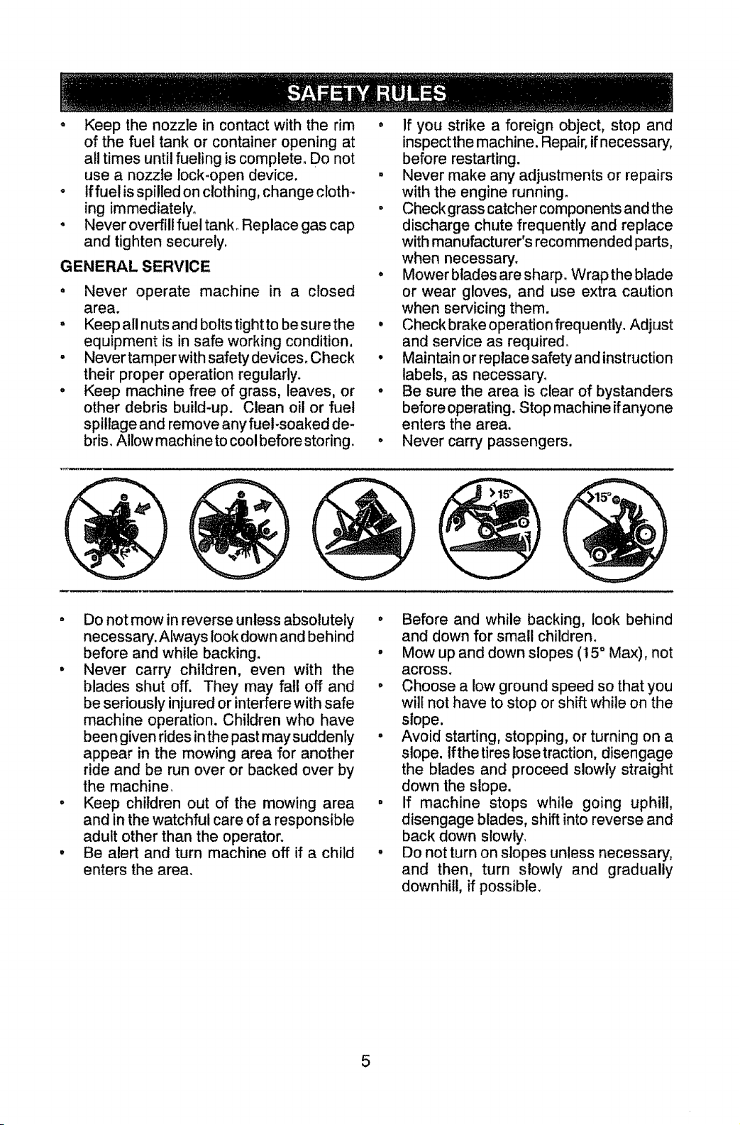
. Mow up and down slopes (15 ° Max), not
across.
° Choose a low ground speed so that you
will not have to stop or shift while on the
slope.
• Avoid starting, stopping, or turning on a
slope. Ifthe tires lose traction, disengage
the blades and proceed slowly straight
down the slope.
o If machine stops while going uphill,
disengage blades, shift into reverse and
back down slowly,
° Do not turn on slopes unless necessary,
and then, turn slowly and gradually
downhill, if possible,
5
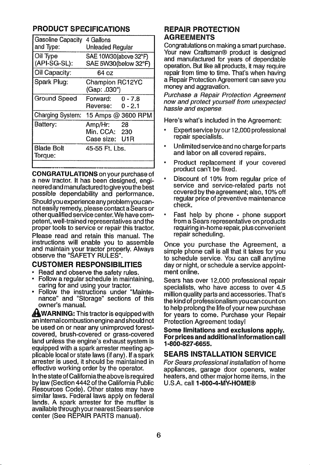
PRODUCT SPECiFICATiONS
Gasoline Capacity 4 Gallons
and Type: Unleaded Regular
Oil Type SAE t0W30(above 32°F)
(API-SG-SL): SAE 5W30(below 32°F)
Oil Capacity: 64 oz
Spark Plug: Champion RC12YC
(Gap: .030")
Ground Speed Forward: 0 - 7.8
Reverse: 0 - 2.1
Charging System: !5 Amps @ 3600 RPM
Battery: AmpiHr: 28
Mino CCA: 230
Case size: U1 R
Blade Bolt 45-55 Ft. Lbso
Torque:
_w
CONGRATULATIONS on your purchase of
a new tractor. It has been designed, engi-
neered and manufactured to give you the best
possible dependability and performance.
Should you experience any problem you can-
not easily remedy, please contact a Sears or
other qualified service center. We have com-
petent, well-trained representatives and the
proper tools to service or repair this tractor.
Please read and retain this manual. The
instructions will enable you to assemble
and maintainyour tractor properly. Always
observe the "SAFETY RULES".
CUSTOMER RESPONSIBILITIES
, Read and observe the safety rules.
• Follow a regular schedule in maintaining,
caring for and using your tractor;,
• Follow the instructions under Mainte-
nance" and "Storage" sections of this
owner's manual.
_I_WARNING: This tractor is equipped with
an internal combustion engine and should not
be used on or near any unimproved forest-
covered, brush-covered or grass-covered
land unless the engine's exhaust system is
equipped with a spark arrester meeting ap-
plicable local or state laws (if any)° If a spark
arrester is used, it should be maintained in
effective working order by the operator,
In the state of California the above is required
by law (Section 4442 of the California Public
Resources Code). Other states may have
similar laws. Federal laws apply on federal
lands. A spark arrester for the muffler is
available through your nearest Sears service
center (See REPAIR PARTS manual).
REPAIR PROTECTION
AGREEMENTS
Congratulations on making a smart purchase.
Your new Craftsman® product is designed
and manufactured for years of dependable
operation. But like all products, it may require
repair from time to time. That's when having
a Repair Protection Agreement can save you
money and aggravation.
Purchase a Repair Protection Agreement
now and protect yourself from unexpected
hassle and expense
Here's what's included in the Agreement:
• Expert service byour 12,000 professional
repair specialists.
° Unlimited service and no charge for parts
and labor on all covered repairs.
- Product replacement if your covered
product can't be fixed.
Discount of 10% from regular price of
service and service-related parts not
covered by the agreement; also, 10% off
regular price of preventive maintenance
check.
Fast help by phone - phone support
from a Sears representative on products
requiring in-home repair, plus convenient
repair scheduling.
Once you purchase the Agreement, a
simple phone call is all that it takes for you
to schedule service. You can cal! anytime
day or night, or schedule a service appoint-
ment online.
Sears has over 12,000 professional repair
specialists, who have access to over 4°5
million quality parts and accessories_ That's
the kind of professionalism you can count on
to help prolong the life of your new purchase
for years to come. Purchase your Repair
Protection Agreement todayl
Some limitations and exclusions apply.
For prices and additional information call
1-800-827-6655.
SEARS INSTALLATION SERVICE
For Sears professional installation of home
appliances, garage door openers, water
heaters, and other major home items, in the
U.S.A. call 1-800-4-MY-HOME®
6
©
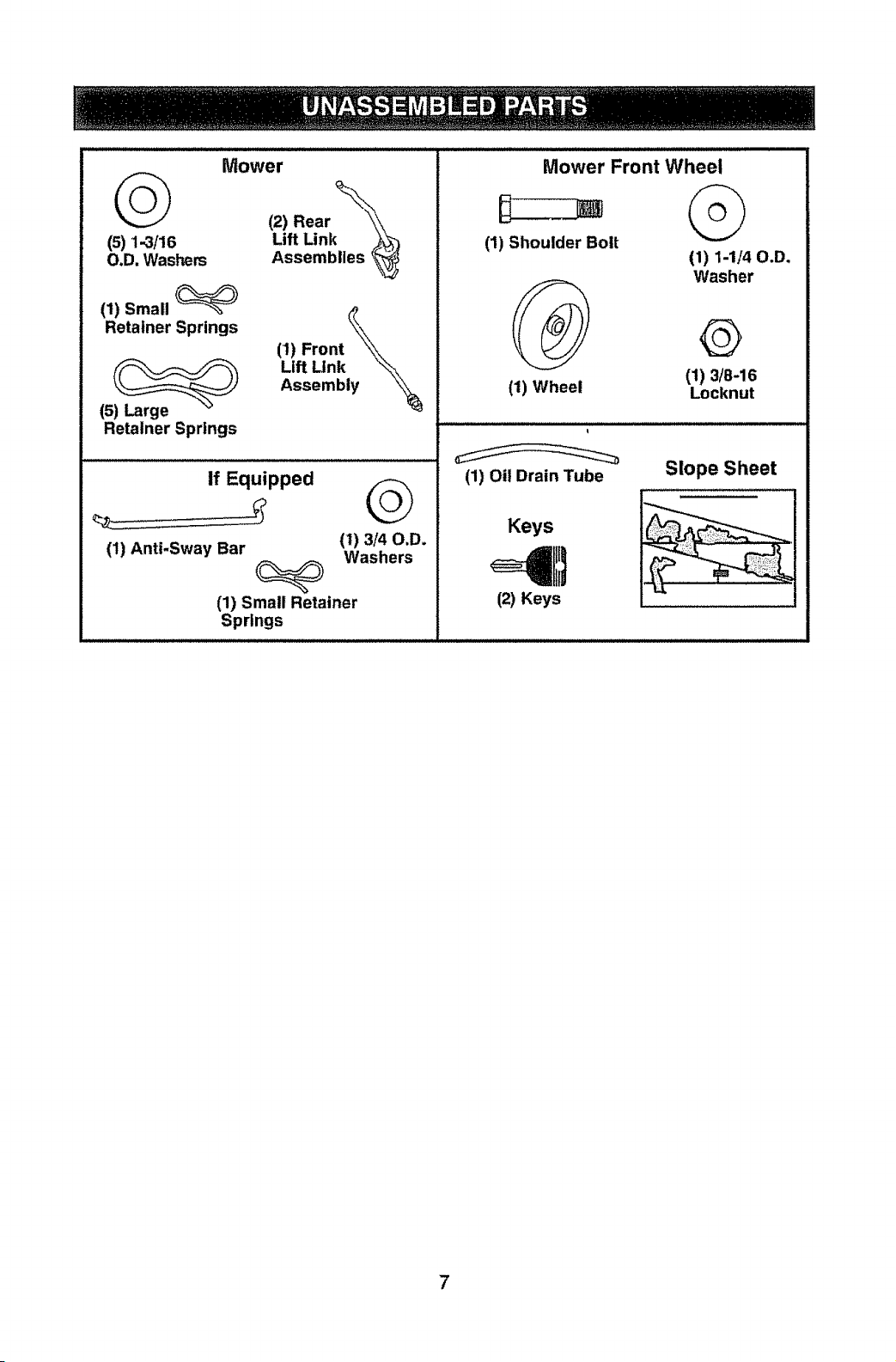
(s)1..3/_6
O.D, Washers
Mower
(2) Rear _,\
Lift Link
Assemblies _
(1) Small
Retainer Springs
(5) Large
Retainer Springs
(1) Front
Lift Link
Assembly
If Equipped
(1t Anti-Sway Bar il) 3/40.D.
Washers
(1) Small Retainer
Springs
Mower Front Wheel
W
(1) Shoulder Bolt
(1) Wheel
©
(1) 1-1/40.D,
Washer
©
(1) 3/8-16
Locknut
(1) Oil Drain Tube
Slope Sheet
Keys
(21Keys
Your new tractor has been assembled at the factory with exception of those parts left
unassembled for shipping purposes. To ensure safe and proper operation of your tractor
all parts and hardware you assemble must be tightened securely. Use the correct tools
as necessary to ensure proper tightness.
TOOLS REQUaRED FOR ASSEMBLY
A socket wrench set will make assembly
easier. Standard wrench sizes are listed.
(2) 7/! 6" wrenches Utility knife
(1) I/2" wrench Tire pressure gauge
(1) 3/4" wrench Pliers
(1) 3/4" socket w/drive ratchet
(t) 9/16" wrench Flashlight
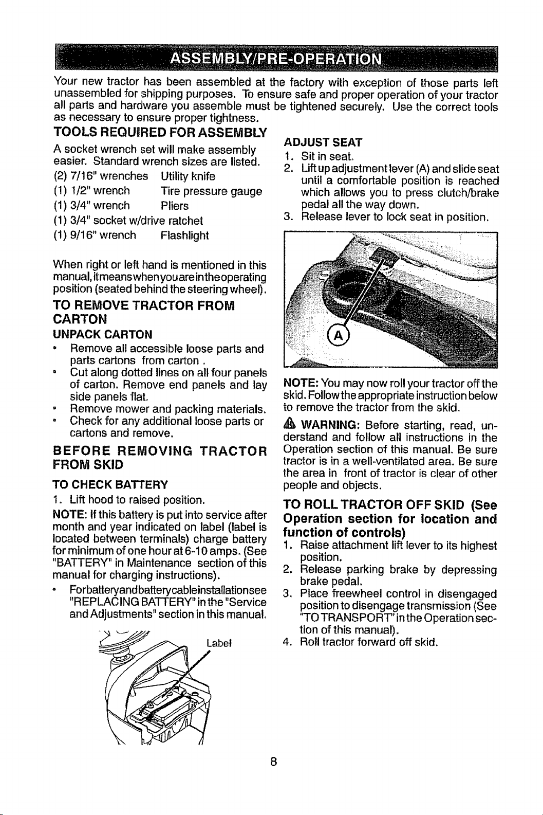
ADJUST SEAT
1. Sit in seat.
2. Liftup adjustment lever (A) and slide seat
until a comfortable position is reached
which allows you to press clutch/brake
pedal all the way down.
3. Release lever to lock seat in position.
When right or left hand is mentioned in this
man ual, it means when you are in the ope rating
position (seated behind the steering wheel).
TO REMOVE TRACTOR FROM
CARTON
UNPACK CARTON
• Remove all accessible loose parts and
parts cartons from carton o
, Cut along dotted lines on all four panels
of carton. Remove end panels and lay
side panels flato
= Remove mower and packing materials.
° Check for any additional loose parts or
cartons and remove.
BEFORE REMOVING TRACTOR
FROM SKID
TO CHECK BATTERY
t. Lift hood to raised position.
NOTE: tf this battery is put into service after
month and year indicated on label (label is
located between terminals) charge battery
for minimum of one hour at 6-10 amps. (See
"BATTERY" in Maintenance section of this
manual for charging instructions).
• Forbatteryand batterycableinstallationsee
"REPLACING BATTERY" inthe "Service
and Adjustments" section in this manual°
#,
abet
NOTE: You may now roll your tractor off the
skid. Followthe appropriate instruction below
to remove the tractor from the skid.
WARNING: Before starting, read, un-
derstand and follow all instructions in the
Operation section of this manual° Be sure
tractor is in a well-ventilated area. Be sure
the area in front of tractor is clear of other
people and objects.
TO ROLL TRACTOR OFF SKiD (See
Operation section for location and
function of controls)
1. Raise attachment lift lever to its highest
position,
2. Release parking brake by depressing
brake pedal.
3. Place freewheel control in disengaged
position to disengage transmission (See
'q'O TRANSPORT" inthe Operation sec-
tion of this manual).
4. Roll tractor forward off skid.
8
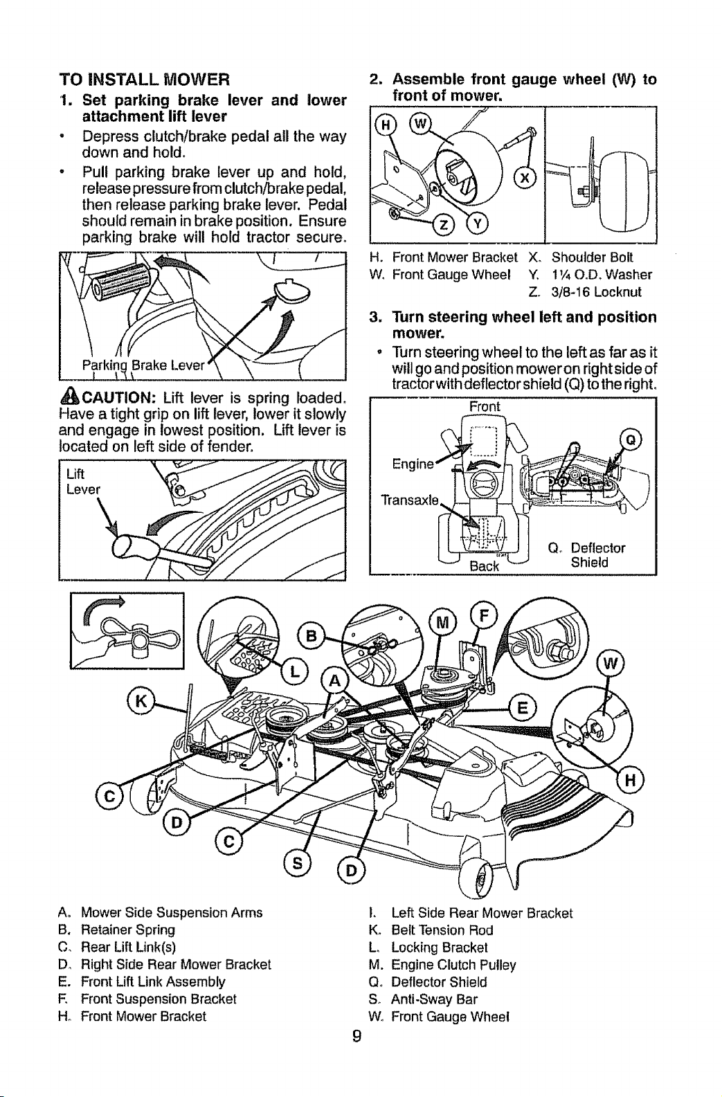
TO INSTALL MOWER
1. Set parking brake lever and lower
attachment lift lever
° Depress clutch/brake pedal all the way
down and hold.
Pul! parking brake lever up and hold,
release pressure from clutch/Drake pedal,
then release parking brake lever. Pedal
should remain in brake position. Ensure
parking brake will hold tractor secure°
Parkinc Brake Lever
_CAUTION: Lift lever is spring loaded.
Have a tight grip on lift lever, lower it slowly
and engage in lowest position. Lift lever is
located on left side of fender°
Lift
Lever
2, Assemble front gauge wheel (W) to
front of mower.
H. Front Mower Bracket X_ Shoulder Bolt
W, Front Gauge Wheel Y, 1t/40°D, Washer
Zo 3/8-16 Locknut
3. Turn steering wheel left and position
mower.
o Turnsteering wheel to the leftas far as it
willgo and positionmower on rightside of
tractor withdeflector shield (Q) tothe right,
Front
Transaxle
Qo Deflector
Shield
Ao Mower Side Suspension Arms
B. Retainer Spring
C, Rear Lift Link(s)
Do Right Side Rear Mower Bracket
E. Front Lift Link Assembly
E Front Suspension Bracket
Ho Front Mower Bracket
I,
Ko
L
M.
Qo
So
Wo
9
Left Side Rear Mower Bracket
Belt Tension Rod
Locking Bracket
Engine Clutch Pulley
Deflector Shield
Anti-Sway Bar
Front Gauge Wheel
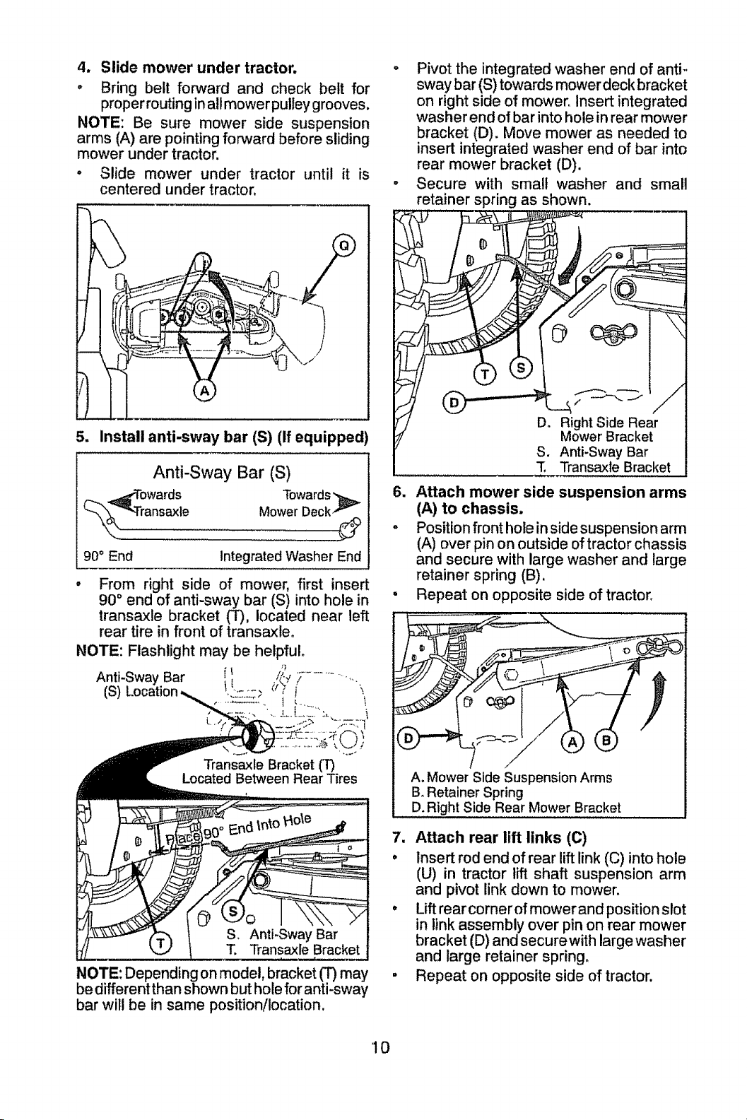
4. Slide mower under tractor,
o Bring belt forward and check belt for
proper routing in all mower pulley grooves.
NOTE: Be sure mower side suspension
arms (A) are pointing forward before sliding
mower under tractor.
° Slide mower under tractor until it is
centered under tractor.
5. Install anti-sway bar (S) (If equipped)
Anti-Sway Bar (S)
_d'Towards Towards
Mower Deck -F-
_-"k_ Transaxle :
90° End Integrated Washer End
• From right side of mower, first insert
90 ° end of anti-sway bar (S) into hole in
transaxle bracket (T), located near left
rear tire in front of transaxleo
NOTE: Flashlight may be helpful.
s_
Bar f l ./_-_'_...................
f ":
(S) i' ......... _,
>_ .......... T, ,
c ,,z ";,-_,71'
t. ",_
_CJI
Transaxle Bracket (T)
Located Between Rear Tires
• Pivot the integrated washer end of anti.,
sway bar (S) towards mower deck bracket
on right side of mower. Insert integrated
washer end of bar into hole in rear mower
bracket (D). Move mower as needed to
insert integrated washer end of bar into
rear mower bracket (D).
° Secure with small washer and small
retainer spring as shown.
Do Right Side Rear
Mower Bracket
S. Anti-Sway Bar
T Transaxle Bracket
Attach mower side suspension arms
(A) to chassis,
. Position front hole in side suspension arm
(A) over pin on outside of tractor chassis
and secure with large washer and large
retainer spring (B).
• Repeat on opposite side of tractor.
A. Mower Side Suspension Arms
B. Retainer Spring
D. Right Side Rear Mower Bracket
1". Transaxle Bracket
NOTE: Depending on model, bracket (T) may
be differentthan shown but hole for anti-sway
bar wilt be in same position/location.
7. Attach rear lift links (C)
• Insert rod end of rear lift link (C) into hole
(U) in tractor lift shaft suspension arm
and pivot link down to mower°
° Lift rear cornerof mower and position slot
in link assembly over pin on rear mower
bracket (D) and secure with large washer
and large retainer spring.
• Repeat on opposite side of tractor,
10
,,,,,
\
\
\
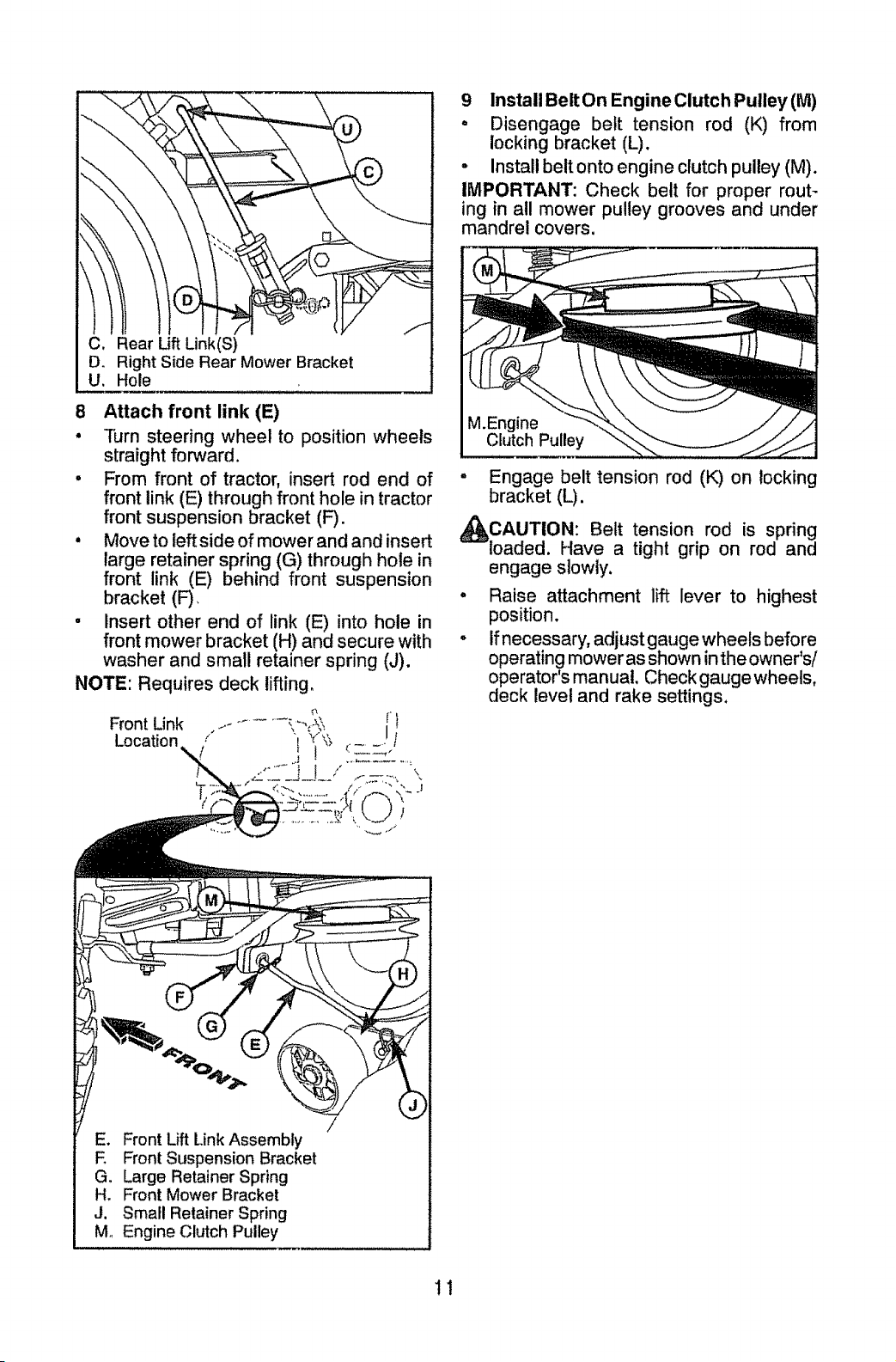
C_
D_
U.
l
Rear Lift Link(S)
Right Side Rear Mower Bracket
Hole
8 Attach front link (E)
• Turn steering wheel to position wheels
straight forward.
• From front of tractor, insert rod end of °
front link (E) through front hole in tractor
front suspension bracket (F).
° Move to left side of mower and and insert
large retainer spring (G) through hole in
front link (E) behind front suspension
bracket (F)_ "
• Insert other end of link (E) into hole in
front mower bracket (H) and secure with °
washer and small retainer spring (J).
NOTE: Requires deck lifting.
9 InstalI Belt On EngineClutch Pulley(M)
o Disengage belt tension rod (K) from
locking bracket (L).
• Install belt onto engine clutch pulley (M).
IMPORTANT: Check belt for proper rout-
ing in all mower pulley grooves and under
mandrel covers.
M,Engine
Clutch Pulley
Engage belt tension rod (K) on locking
bracket (L).
_CAUTION: Belt tension rod is spring
loaded. Have a tight grip on rod and
engage slowly.
Raise attachment lift lever to highest
position.
If necessary, adjust gauge wheels before
operating mower as shown in the owner's/
operator's manual, Check gaugewheels,
deck level and rake settings,
E. Front Lift Link Assembly
E Front Suspension Bracket
G. Large Retainer Spring
H, Front Mower Bracket
J. Small Retainer Spring
M_ Engine Clutch Pulley
11
CHECK TiRE PRESSURE
The tires on your tractor were over-inflated
at the factory for shipping purposes. Correct
tire pressure is important for best cutting
performance.
• Reduce tire pressureto PSI shown on tires.
CHECK DECK LEVELNESS
For best cutting results, mower housing
should be properly leveled. See "TO LEVEL
MOWER" in the Service and Adjustments
section of this manual.
CHECK FOR PROPER POSITION OF
ALL BELTS
See the figures that are shown for replacing
motion and mower blade drive belts in the
Service and Adjustments section of this man-
ual. Verify that the belts are routed correctly.
CHECK BRAKE SYSTEM
After you learn how to operate your tractor,
check to see that the brake is operating prop-
erly, See "TO CHECK BRAKE" in the Service
and Adjustments section of this manual
_f'CHECKLiST
Before you operate your new tractor, we
wish to assure that you receive the best
performance and satisfaction from this
Quality Product,
Please review the following checklist:
t/f All assembly instructions have been
completed.
_" No remaining loose parts in carton_
v/ Battery is properly prepared and
charged°
J
Seat is adjusted comfortably and tight-
ened securely_
_' All tires are properly inflated. (For ship-
ping purposes, the tires were overinflated
at the factory).
t_ Be sure mower deck is properly leveled
side-to-side/front-to-rear for best cutting
results. (Tires must be properly inflated
for leveling).
_" Check mower and drive belts. Be sure
they are routed properly around pulleys
and inside all belt keepers.
#f Check wiring. See that all connections
are still secure and wires are properly
clamped.
J" Before driving tractor, be sure freewheel
control is in "transmission engaged"
position (see "TO TRANSPORT' in the
Operation section of this manual).
While learning howto use your tractor, pay ex-
tra attention to the fo!lowing important items:
_" Engine oil is at proper level°
v/' Fueltank is filled with fresh, clean, regular
unleaded gasoline,
V" Become familiar with all controls, their
location and function. Operate them
before you start the engine.
Be sure brake system is in safe operating
condition.
tf Be sure Operator Presence System and
Reverse Operation System (ROS) are
working properly (See the Operation and
Maintenance sections in this manual)°
V_ It is important to purge the transmission
before operating your tractor for the first
time. Follow proper starting and transmis.
sion purging instructions (See 'TO START
ENGINE" and "PURGE TRANSMISSION"
in the Operation section of this manual).
12
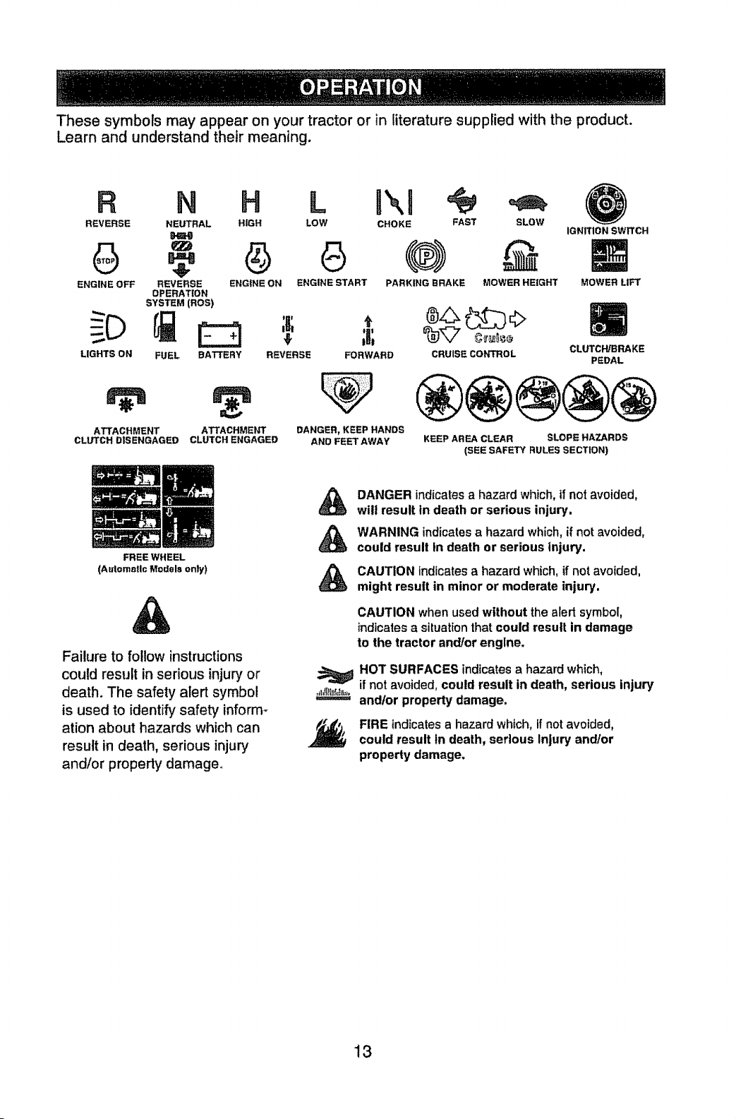
These symbols may appear on your tractor or in literature supplied with the product.
Learn and understand their meaning.
R N H L
REVERSE NEUTRAL HIGH LOW
ENGINE OFF REVERSE ENGINE ON ENGINE START
OPERATION
SYSTEM (ROS)
LIGHTS ON
FUEL
ATTACHMENT
CLUTCH DISENGAGED
CHOKE FAST SLOW
PARKING BRAKE MOWER HEIGHT
IGNITION SWITCH
MOWERLtFT
BATTERY REVERSE FORWARD
ATTACHMENT DANGER, KEEP HANDS
CLUTCH ENGAGED AND FEET AWAY
CRUISE CONTROL
CLUTCH/BRAKE
PEDAL
®@@@@
KEEP AREA CLEAR SLOPE HAZARDS
(SEE SAFETY RULES SECTION)
FREE WHEEL
(Autometl¢ Models only)
DANGER indicates a hazard which, if not avoided,
wilt result tn death or serious injury.
WARNING indicates a hazard which, if not avoided,
could result In death or serious injury.
Failure to follow instructions
could result in serious injury or
death. The safety alert symbol
is used to identify safety inform-
ation about hazards which can
result in death, serious injury
and/or property damage°
CAUTION indicates a hazard which, if not avoided,
might result in minor or moderate injury.
CAUTION when used without thealert symbol,
indicatesa situationthat could result in damage
to the tractor and/or engine.
HOT SURFACES indicates a hazard which,
if not avoided, could result in death, serious injury
and/or property damage,
FIRE indicates a hazard which, if not avoided,
could result In death, serious Injury and/or
property damage,
t3
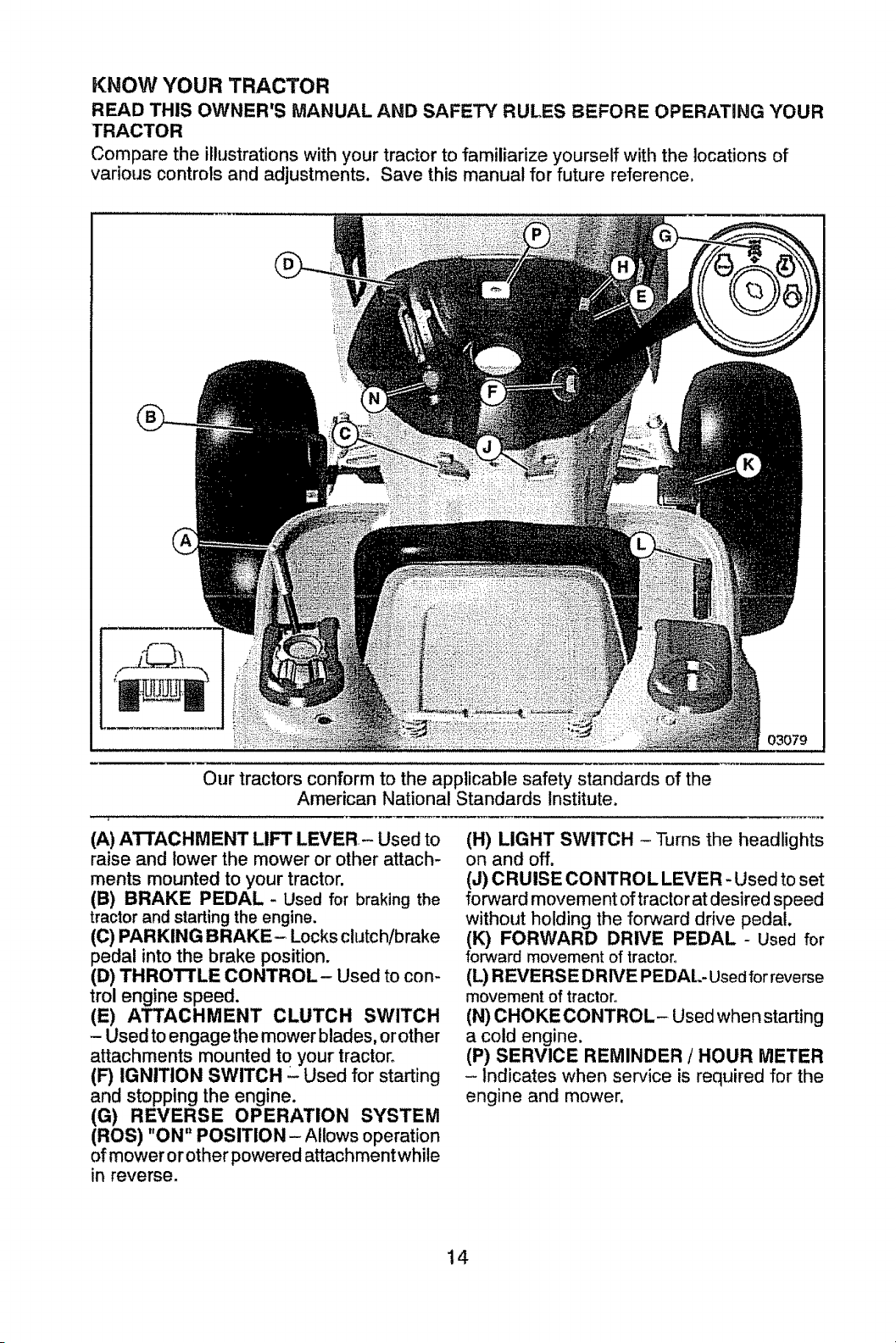
KNOW YOUR TRACTOR
READ THIS OWNEWS MANUAL AND SAFETY RULES BEFORE OPERATING YOUR
TRACTOR
Compare the illustrations with your tractor to familiarize yourself with the locations of
various controls and adjustments. Save this manual for future reference.
Our tractors conform to the applicable safety standards of the
American National Standards institute,
(A) ATTACHMENT LIFT LEVER- Used to
raise and lower the mower or other attach-
ments mounted to your tractor.
(B) BRAKE PEDAL - Used for braking the
tractor and starting the engine.
(C) PARKING BRAKE- Locks clutch/brake
pedal into the brake position.
(D) THROTTLE CONTROL- Used to con-
trol engine speed.
(E) ATTACHMENT CLUTCH SWITCH
- Used to engage the mower blades, orother
attachments mounted to your tractor°
(F) IGNITION SWITCH - Used for starting
and stopping the engine.
(G) REVERSE OPERATION SYSTEM
(ROS) "ON" POSITION - Allows operation
of mower or other powered attachment while
in reverse.
(H) LIGHT SWITCH - Turns the headlights
on and off.
(J) CRUISE CONTROL LEVER - Used to set
forward movement of tractor at desired speed
without holding the forward drive pedal,
(K) FORWARD DRIVE PEDAL - Used for
forward movement of tractor,
(L) REVERS E DR WE PEDAL- Used for reverse
movement of tractor°
(N) CHOKE CONTROL- Used when starting
a cold engine.
(P) SERVICE REMINDER / HOUR METER
- Indicates when service is required for the
engine and mower.
14
The operation of any tractor can result in foreign objects thrown into the
eyes, which can result in severe eye damage. Always wear safety glasses
or eye shields while operating your tractor or performing any adjustments
or repairs. We recommend standard safety glasses or a wide vision safety
mask worn over spectacles.
HOW TO USE YOUR TRACTOR
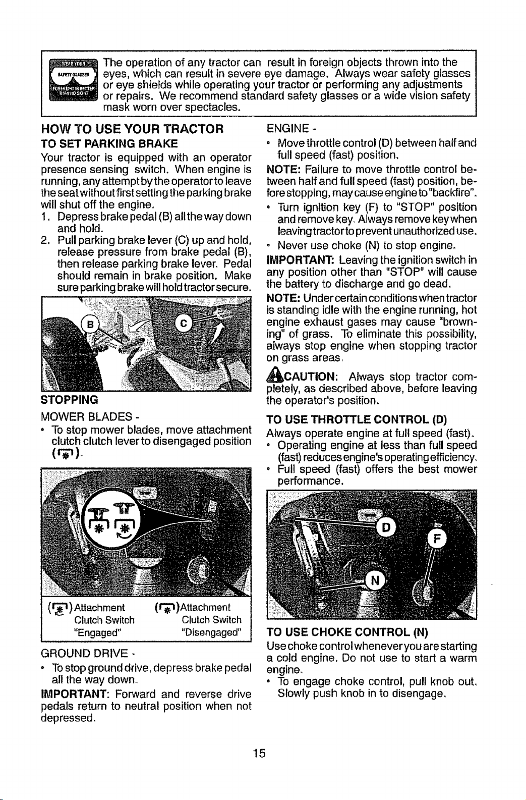
TO SET PARKING BRAKE
",(our tractor is equipped with an operator
presence sensing switch. When engine is
running, any attempt by the operatorto leave
the seat withoutfirst setting the parking brake
will shut off the engine.
1. Depress brake pedal (B) allthe way down
and hold.
2. Pull parking brake lever (C) up and hold,
release pressure from brake pedal (B),
then release parking brake lever. Pedal
should remain in brake position. Make
sure parking brake wilt hold tractor secure.
STOPPING
MOWER BLADES -
" To stop mower blades, move attachment
clutch clutch lever to disengaged position
(r_'t) Attachment
Clutch Switch
"Engaged"
(r_l)Attachment
Clutch Switch
"Disengaged"
GROUND DRIVE -
° To stop ground drive, depress brake pedal
all the way down.
IMPORTANT: Forward and reverse drive
pedals return to neutral position when not
depressed.
ENGINE -
o Move throttle control (D) between half and
full speed (fast) position.
NOTE: Failure to move throttle control be-
tween half and full speed (fast) position, be-
fore stopping, may cause engine to "backfire".
, Turn ignltion key (F) to "STOP" position
and remove key_ Always remove keywhen
leaving tractor to prevent unauthorized use.
° Never use choke (N) to stop engine.
IMPORTANT: Leaving the ignition switch in
any position other than "STOP" will cause
the battery to discharge and go dead°
NOTE: Undercertain conditionswhentractor
is standing idle with the engine running, hot
engine exhaust gases may cause "brown-
ing" of grass. To eliminate this possibility,
always stop engine when stopping tractor
on grass areas_
_CAUTION: Always stop tractor com-
pletely, as described above, before leaving
the operator's position.
TO USE THROTTLE CONTROL (D)
Always operate engine at full speed (fast)°
o Operating engine at less than full speed
(fast)reduces engine'soperatingefficiency,
° Full speed (fast) offers the best mower
performance.
TO USE CHOKE CONTROL (N)
Use choke control whenever you are starting
a cold engine. Do not use to start a warm
engine.
° To engage choke control, pull knob out.
Slowly push knob in to disengage.
15
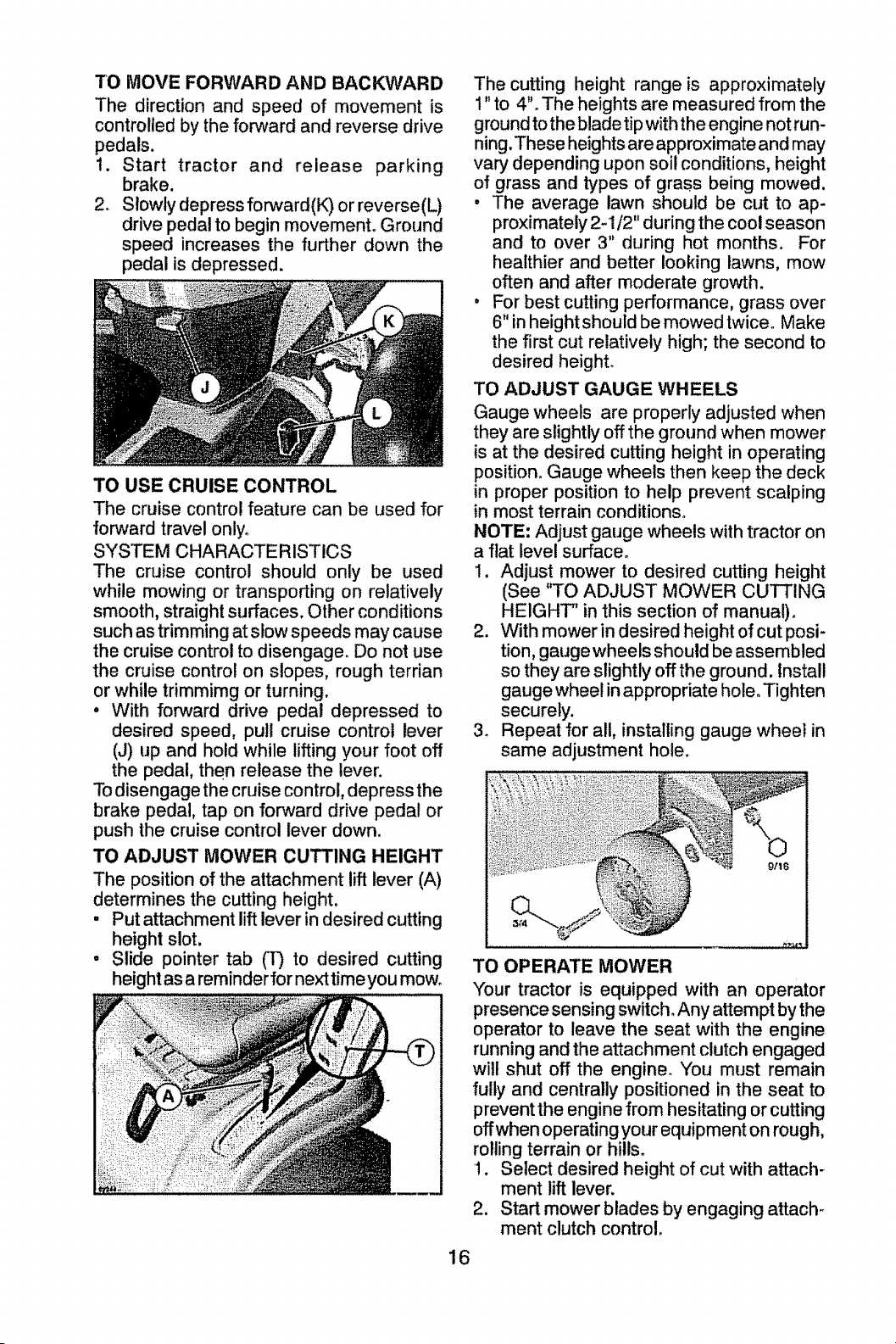
TO MOVE FORWARD AND BACKWARD
The direction and speed of movement is
controlled by the forward and reverse drive
pedals.
1. Start tractor and release parking
brake.
2. Slowly depress forward(K) or reverse(L)
drive pedal to begin movement° Ground
speed increases the further down the
pedal is depressed.
TO USE CRUISE CONTROL
The cruise control feature can be used for
forward travel only.
SYSTEM CHARACTERISTICS
The cruise control should only be used
while mowing or transporting on relatively
smooth, straight surfaces. Other conditions
such as trimming at slow speeds may cause
the cruise controlto disengage. Do not use
the cruise control on slopes, rough terrian
or while trimmimg or turning.
° With forward drive pedal depressed to
desired speed, pull cruise control lever
(J) up and hold while lifting your foot off
the pedal, then release the lever.
To disengage the cruise control, depress the
brake pedal, tap on forward drive pedal or
push the cruise control lever down.
TO ADJUST MOWER CUTTING HEIGHT
The position of the attachment lift lever (A)
determines the cutting height.
, Put attachment liftlever indesired cutting
height slot.
• Slide pointer tab (1") to desired cutting
heightas a reminder for next timeyou mow.
The cutting height range is approximately
1" to 4". The heights are measured from the
ground to the blade tip with the engine not run-
ning. These heights are approximate and may
vary depending upon soil conditions, height
of grass and types of grass being mowed.
, The average lawn should be cut to ap-
proximately 2-1/2" during the cool season
and to over 3" during hot months. For
healthier and better looking lawns, mow
often and after moderate growth.
° For best cutting performance, grass over
6" in height should be mowed twice. Make
the first cut relatively high; the second to
desired height
TO ADJUST GAUGE WHEELS
Gauge wheels are properly adjusted when
they are slightly off the ground when mower
is at the desired cutting height in operating
position. Gauge wheels then keep the deck
in proper position to help prevent scalping
in most terrain conditions°
NOTE: Adjust gauge wheels with tractor on
a flat level surface°
1. Adjust mower to desired cutting height
(See "TO ADJUST MOWER CUTTING
HEIGHT' in this section of manual).
2. With mower in desired height of cut posi-
tion, gauge wheels should be assembled
so they are slightly offthe ground. Install
gauge wheel in appropriate hole. Tighten
securely.
3. Repeat for all, installing gauge wheel in
same adjustment hole.
TO OPERATE MOWER
Your tractor is equipped with an operator
presence sensing switch. Any attempt by the
operator to leave the seat with the engine
running and the attachment clutch engaged
will shut off the engine. You must remain
fully and centrally positioned in the seat to
prevent the engine from hesitating or cutting
offwhen operating your equipment on rough,
rolling terrain or hills.
1. Select desired height of cut with attach-
ment lift lever.
2. Start mower blades by engaging attach-
ment clutch control.
16
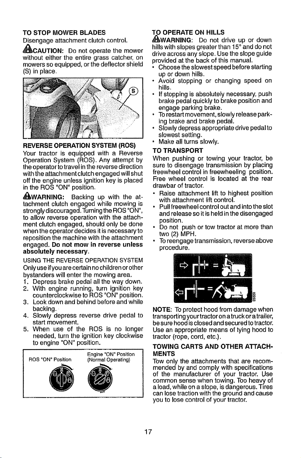
TO STOP MOWER BLADES
Disengage attachment clutch control.
_CAUTION: Do not operate the mower
without either the entire grass catcher, on
mowers so equipped, or the deflector shield
(S) in place.
REVERSE OPERATION SYSTEM (ROS)
Your tractor is equipped with a Reverse
Operation System (ROS). Any attempt by
the operator to travel in the reverse direction
with the attachment clutch engaged will shut
off the engine unless ignition key is placed
in the ROS "ON" position_
_WARNING: Backing up with the at-
tachment clutch engaged while mowing is
strongly discouraged.'Pdrning the ROS "ON",
to allow reverse operation with the attach-
ment clutch engaged, should only be done
when the operator decides it is necessary to
reposition the machine with the attachment
engaged. Do not mow in reverse unless
absolutely necessary.
USING THE REVERSE OPERATION SYSTEM
Only use ifyou are certain no children or other
bystanders will enter the mowing area°
I. Depress brake pedal all the way down.
2. With engine running, turn ignition key
counterclockwise to ROS "ON" position.
3. Look down and behind before and while
backing.
4. Slowly depress reverse drive pedal to
start movement.
5. When use of the ROS is no longer
needed, turn the ignition key clockwise
to engine "ON" position.
ROS "ON" Position
Engine "ON" Position
(Normal Operating)
3"0 OPERATE ON HILLS
_WARNING: Do not drive up or down
hills with slopes greater than 15 ° and do not
drive across any slope. Use the slope guide
provided at the back of this manual.
, Choose the slowest speed before starting
up or down hills.
, Avoid stopping or changing speed on
hills_
° If stopping is absolutely necessary, push
brake pedal quickly to brake position and
engage parking brake.
• To restart movement, slowly release park-
ing brake and brake pedal.
, Slowly depress appropriate drive pedal to
slowest setting.
, Make all turns slowly.
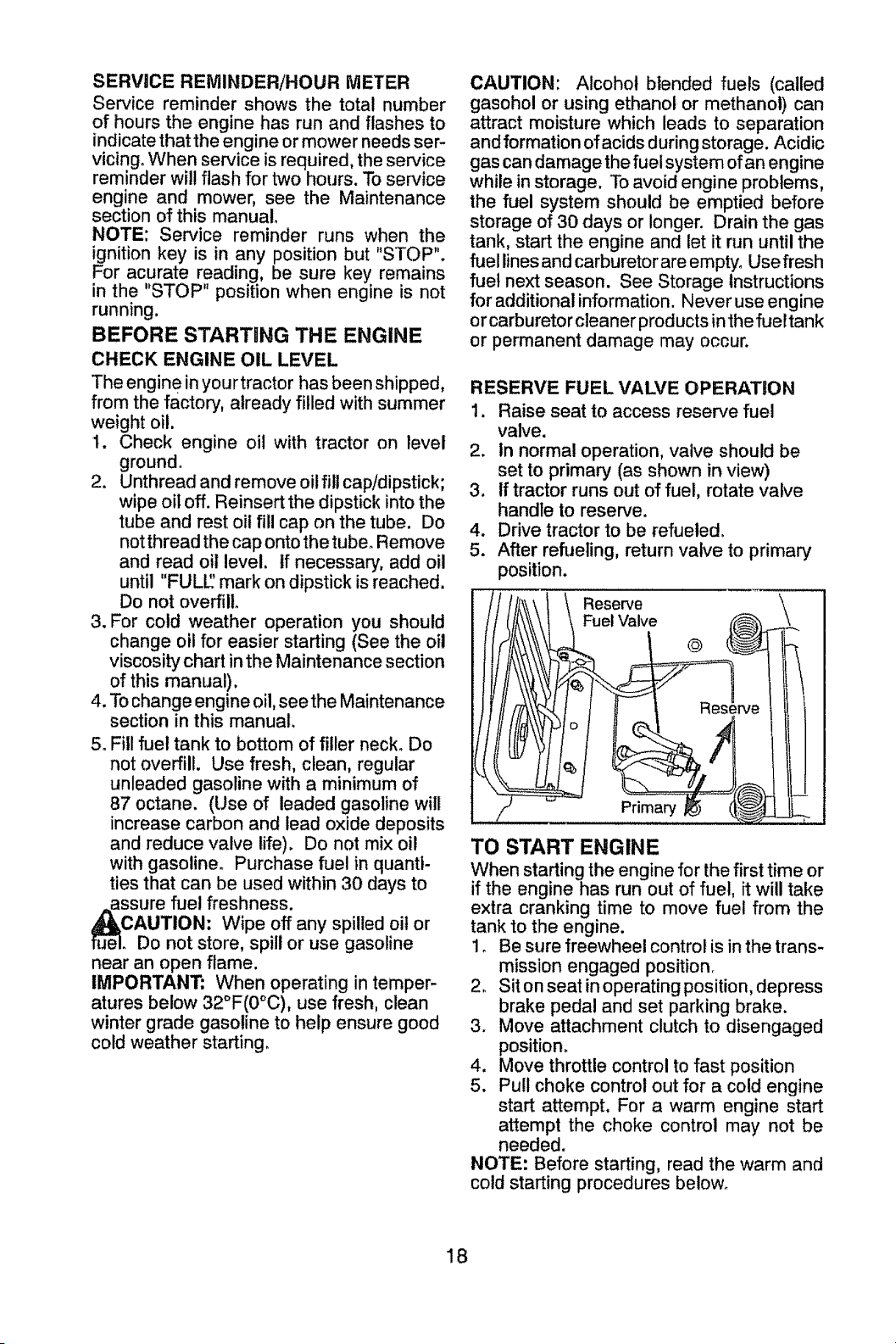
TO TRANSPORT
When pushing or towing your tractor, be
sure to disengage transmission by placing
freewheel control in freewheeling position.
Free wheel control is located at the rear
drawbar of tractor_
• Raise attachment lift to highest position
with attachment lift control.
, Pull freewheel control out and into the slot
and release so it is held in the disengaged
position.
, Do not push or tow tractor at more than
two (2) MPH.
, To reengage transmission, reverse above
procedure.
NOTE: To protect hood from damage when
transporting your tractor on a truck or atrailer,
be sure hood is closed and secured to tractor.
Use an appropriate means of tying hood to
tractor (rope, cord, etc.).
TOWING CARTS AND OTHER ATTACH-
MENTS
Tow only the attachments that are recom-
mended by and comply with specifications
of the manufacturer of your tractor. Use
common sense when towing. Too heavy of
a load, while on a slope, is dangerous. Tires
can lose traction with the ground and cause
you to lose control of your tractor.
17
SERVICE REMINDER/HOUR METER
Service reminder shows the total number
of hours the engine has run and flashes to
indicate that the engine or mower needs ser-
vicing° When service is required, the service
reminder will flash for two hours. To service
engine and mower, see the Maintenance
section of this manual.
NOTE: Service reminder runs when the
ignition key is in any position but "STOP".
For acurate reading, be sure key remains
in the "STOP" position when engine is not
running.
BEFORE STARTING THE ENGINE
CHECK ENGINE OIL LEVEL
The engin e in your tractor has been shipped,
from the factory, already filled with summer
weight oil.
t. Check engine oil with tractor on level
ground°
2. Unthread and remove oil fill cap!dipstick;
wipe oil off. Reinsert the dipstick into the
tube and rest oil fill cap on the tube. Do
not thread the cap onto the tube. Remove
and read oil level, tf necessary, add oil
until "FULE' mark on dipstick is reached.
Do not overfill.
3. For cold weather operation you should
change oil for easier starting (See the oil
viscosity chart in the Maintenance section
of this manual).
4. To change engine oil, seethe Maintenance
section in this manual.
5. Fill fuel tank to bottom of filler neck. Do
not overfill. Use fresh, clean, regular
unleaded gasoline with a minimum of
87 octane. (Use of leaded gasoline will
increase carbon and lead oxide deposits
and reduce valve life). Do not mix oil
with gasoline. Purchase fuel in quanti-
ties that can be used within 30 days to
assure fuel freshness.
CAUTION: Wipe off any spilled oil or
. Do not store, spill or use gasoline
near an open flame.
IMPORTANT; When operating in temper-
atures below 32°F(0°C), use fresh, clean
winter grade gasoline to help ensure good
cold weather starting_
CAUTION: Alcohol blended fuels (called
gasohol or using ethanol or methanol) can
attract moisture which leads to separation
and formation of acids during storage. Acidic
gas can damage the fuel system of an engine
while in storage, To avoid engine problems,
the fuel system should be emptied before
storage of 30 days or longer. Drain the gas
tank, start the engine and let it run until the
fuel lines and carburetor are empty° Use flesh
fuel next season. See Storage Instructions
for additional information. Neveruse engine
or carburetor cleaner products in the fuel tank
or permanent damage may occur.
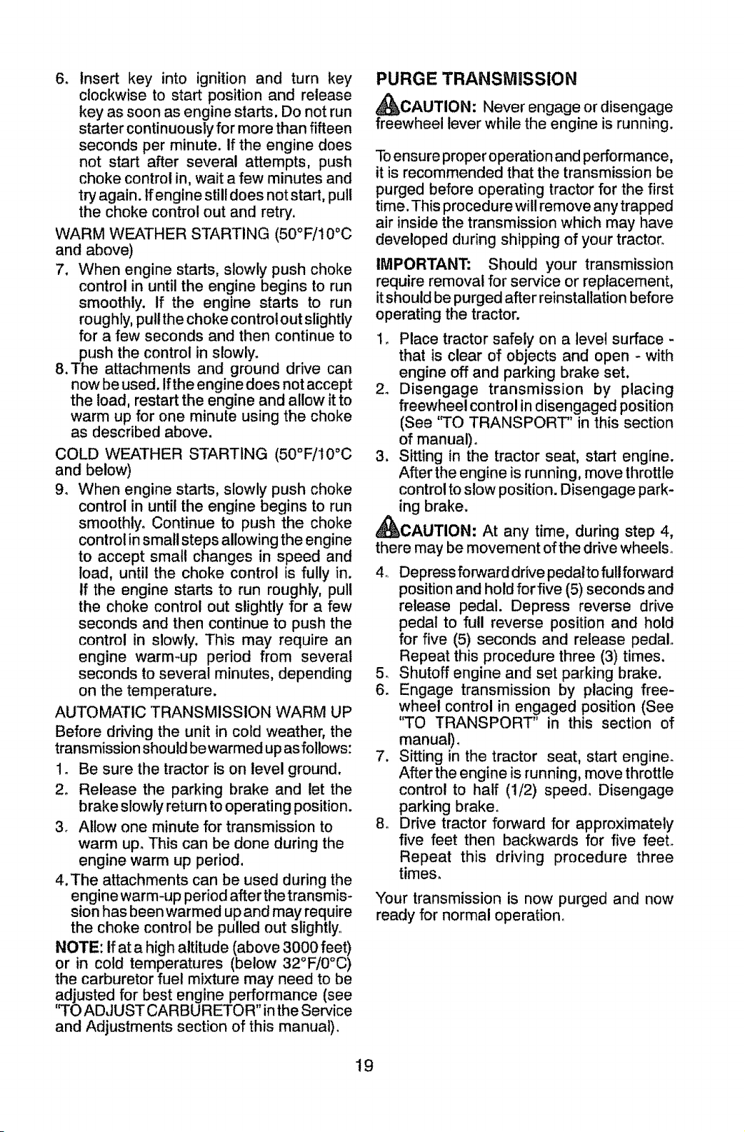
RESERVE FUEL VALVE OPERATION
1. Raise seat to access reserve fuel
valve.
2. In normal operation, valve should be
set to primary (as shown in view)
3, If tractor runs out of fuel, rotate valve
handle to reserve.
4. Drive tractor to be refueled.
5. After refueling, return valve to primary
position.
Reserve
Fuel Valve
©
Primary
TO START ENGINE
When starting the engine for the first time or
if the engine has run out of fue!, it will take
extra cranking time to move fuel from the
tank to the engine.
i. Be sure freewheel control is in the trans-
mission engaged position.
2. Sit on seat in operating position, depress
brake pedal and set parking brake.
3. Move attachment clutch to disengaged
position.
4. Move throttle control to fast position
5. Pull choke control out for a cold engine
start attempt, For a warm engine start
attempt the choke control may not be
needed.
NOTE: Before starting, read the warm and
cold starting procedures below_
18
6. Insert key into ignition and turn key
clockwise to start position and release
key as soon as engine starts. Do not run
starter continuously for more than fifteen
seconds per minute, If the engine does
not start after several attempts, push
choke control in, wait a few minutes and
try again. If engine still does not start, pull
the choke control out and retry,
WARM WEATHER STARTING (50°F/i0°C
and above)
7, When engine starts, slowly push choke
control in until the engine begins to run
smoothly, If the engine starts to run
roughly, pull the choke control out slightly
for a few seconds and then continue to
push the control in slowly.
8.The attachments and ground drive can
now be used, If the engine does not accept
the load, restart the engine and allow it to
warm up for one minute using the choke
as described above,
COLD WEATHER STARTING (50°F/t0°C
and below)
9, When engine starts, slowly push choke
control in until the engine begins to run
smoothly_ Continue to push the choke
control in small steps allowing the engine
to accept small changes in speed and
load, until the choke control is fully in.
If the engine starts to run roughly, pull
the choke control out slightly for a few
seconds and then continue to push the
control in slowly, This may require an
engine warm-up period from several
seconds to several minutes, depending
on the temperature,
AUTOMATIC TRANSMISSION WARM UP
Before driving the unit in cold weather, the
transmission should be warmed up as follows:
1, Be sure the tractor is on level ground,
2, Release the parking brake and let the
brake slowly return to operating position.
3, Allow one minute for transmission to
warm up, This can be done during the
engine warm up period.
4.The attachments can be used during the
engine warm-up period after the transmis-
sion has been warmed up and may require
the choke control be pulled out slightly°
NOTE: if at a high altitude (above 3000 feet)
or in cold temperatures (below 32°F/0°C)
the carburetor fuel mixture may need to be
adjusted for best engine performance (see
"TO ADJUST CARBURETOR" in the Service
and Adjustments section of this manual),
PURGE TRANSiVt|SSION
_CAUTION: Never engage or disengage
freewheel lever while the engine is running.
To ensure proper operation and performance,
it is recommended that the transmission be
purged before operating tractor for the first
time, This procedure will remove any trapped
air inside the transmission which may have
developed during shipping of your tractor,
IMPORTANT: Should your transmission
require removal for service or replacement,
it should be purged after reinstallation before
operating the tractor.
1, Place tractor safely on a level surface -
that is clear of objects and open - with
engine off and parking brake set.
2, Disengage transmission by placing
freewheel control in disengaged position
(See ''TO TRANSPORT" in this section
of manual),
3, Sitting in the tractor seat, start engine,
After the engine is running, move throttle
control to slow position. Disengage park-
ing brake.
_CAUTION: At any time, during step 4,
there may be movement of the drive wheels_
4. Depress forward drive pedatto full forward
position and hold for five (5) seconds and
release pedal, Depress reverse drive
pedal to full reverse position and hold
for five (5) seconds and release pedal
Repeat this procedure three (3) times.
5, Shutoff engine and set parking brake,
6. Engage transmission by placing free-
wheel control in engaged position (See
"TO TRANSPORT" in this section of
manual),
7. Sitting in the tractor seat, start engine.
After the engine is running, move throttle
control to half (!/2) speed° Disengage
parking brake,
8o Drive tractor forward for approximately
five feet then backwards for five feet,
Repeat this driving procedure three
times,
Your transmission is now purged and now
ready for normal operation,
!9
MOWING TIPS
• Tire chains cannot be used when the
mower housing is attached to tractor_
o Mower should be properly leveled for best
mowing performance, See "TO LEVEL
MOWER HOUSING" in the Service and
Adjustments section of this manual.
o The left hand side of mower should be
used for trimming.
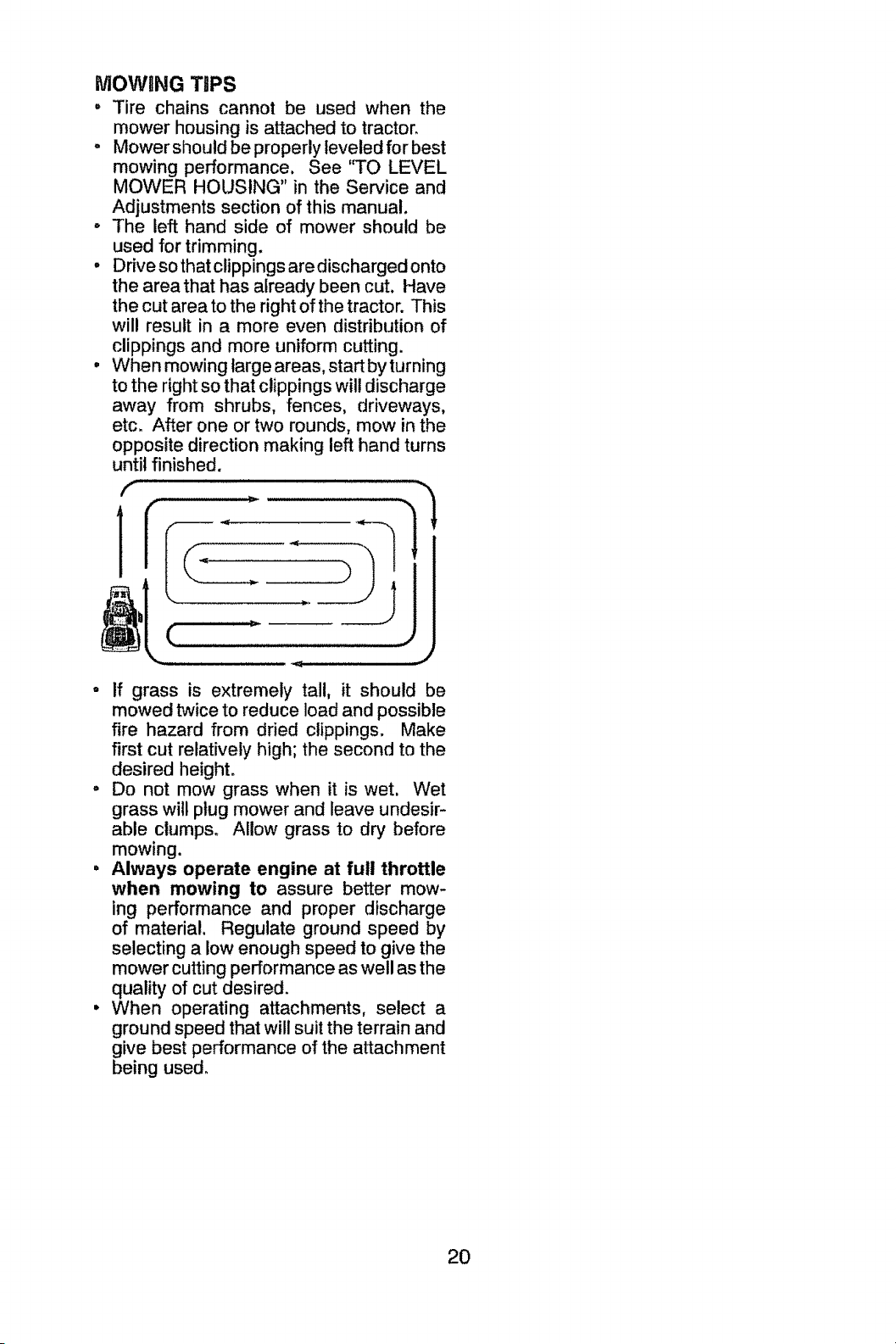
o Drive so that clippings are discharged onto
the area that has already been cut. Have
the cut area to the right of the tractor. This
will result in a more even distribution of
clippings and more uniform cutting.
• When mowing large areas, start by turning
to the right so that clippings will discharge
away from shrubs, fences, driveways,
etc. After one or two rounds, mow in the
opposite direction making left hand turns
until finished.
f
J
• If grass is extremely tall, it should be
mowed twice to reduce load and possible
fire hazard from dried clippings, Make
first cut relatively high; the second to the
desired height,
o Do not mow grass when it is wet. Wet
grass will plug mower and leave undesir-
able clumps, Allow grass to dry before
mowing.
• Always operate engine at full throttle
when mowing to assure better mow-
ing performance and proper discharge
of material. Regulate ground speed by
selecting a low enough speed to give the
mower cutting performance as well as the
quality of cut desired.
° When operating attachments, select a
ground speed that will suit the terrain and
give best performance of the attachment
being used.
2O
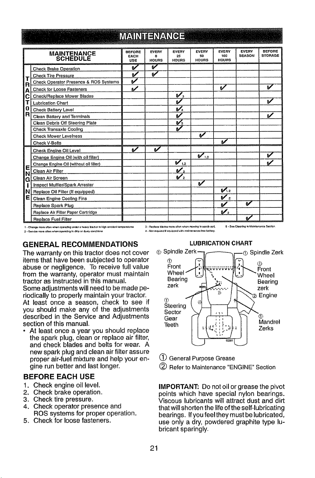
MAINTENANCE
SCHEDULE
Check Brake Operation
Check Tire pressure ................
T
Ch_Ck0p_m,cr_resenc_• ROSSy_tam_
A Check for Loose Fasteners
C ChecWReptace Mower Blades
T Lubrication Chart
0 Check Battery Level
R Clean BalteryandTermlnals .........
Clean Debris Off Sleeting Plate
BEFORI_ EVERY EVERY EVERY EVERY EVERY BEFORE
EACH S 2S 50 "JSO SF_.,.ASON STORAGE
USE HOURS HOURS HOURS HOURS
v"
_,, ....... _ ...... _,-
; . ,
J,
v' ...................... 7
v',
,, = ..............................
v" J
Check Transaxle Cooling ,,
Check Mower Levetness
Check V-Belts
Check Enqine Oil Level
=
.Chart eEn ion O_lw_thoilflIter
_ Change Engine Oit (without oil lIIter)
Clean Air Fgter .............
G : Clean Air Screen ....
I Inspect Muffler/SparkArraster =
N i Replace Oil Fiiler (If equipped)
E I Ciean Engine Cooling Fins
Replace Spark Plug
Reptace Air Filter Paper Cartridge
Reptace Fuel Filter
........v";';..............
_2
I ,.Ct_l_g_ rc_n__nn _n epi=r_tI_gtt_u_trQ h_mff b_ _ _ h_ Qm_la_| l_mpntatum_
GENERAL RECOMMENDATIONS
The warranty on this tractor does not cover
items that have been subjected to operator
abuse or negligence. To receive full value
from the warranty, operator must maintain
tractor as instructed in this manual.
Some adjustments will need to be made pe-
riodically to properly maintain your tractor°
At least once a season, check to see if
you should make any of the adjustments
described in the Service and Adjustments
section of this manual.
• At least once a year you should replace
the spark plug, clean or replace air filter,
and check blades and belts for wear. A
new spark plug and clean air filter assure
proper air-fuel mixture and help your en-
gine run better and last longer,
BEFORE EACH USE
1. Check engine oil level.
2. Check brake operation°
3o Check tire pressure.
4. Check operator presence and
ROS systems for proper operation.
5. Check for loose fasteners.
_'_Spindle
O
Front
Bearing
zerk
Steering _\
Sector
Gear
Teeth
LUBRICATION CHART
_ Spindle Zerk
F_ront
Wheel
Bearing
zerk
'® Engine
Mandrel
Zerks
(_ General Purpose Grease
(_ Refer to Maintenance "ENGINE" Section
IMPORTANT; Do not sit or grease the pivot
points which have special nylon bearings.
Viscous lubricants witl attract dust and dirt
that will shorten the life of the self-lubricating
bearings. If you feel they must be lubricated,
use only a dry, powdered graphite type lu-
bricant sparingly.
21
TRACTOR
Always observe safety rules when performing
any maintenance.
BRAKE OPERATION
If tractor requires more than five (5) feet to
stop at highest speed in highest gear on a
level, dry concrete or paved surface, then
brake must be serviced. (See 'q'O CHECK
BRAKE" in the Service and Adjustments
section of this manual).
TIRES
, Maintain proper air pressure in all tires
(See PSI on tires).
, Keep tires free of gasoline, oil, or insect
control chemicals which can harm rub-
ber.
• Avoid stumps, stones, deep ruts, sharp
objects and other hazards that may cause
tire damage.
NOTE; To seal tire punctures and prevent
flat tires due to stow leaks, tire sealant may
be purchased from your local parts dealer.
Tire sealant also prevents tire dry rot and
corrosion,
OPERATOR PRESENCE SYSTEM AND
REVERSE OPERATION SYSTEM (ROS)
Be sure operator presence and reverse
operation systems are working properly° if
your tractor does not function as described,
repair the problem immediately.
o The engine should not start unless the
brake pedal is fully depressed, and the
attachment clutch control is in the disen-
gaged position_
CHECK OPERATOR PRESENCE
SYSTEM
- When the engine is running, any attempt
by the operator to leave the seat without
first setting the parking brake should shut
off the engine.
° When the engine is running and the at-
tachment clutch is engaged, any attempt
by the operator to leave the seat should
shut off the engine.
• The attachment clutch should never oper-
ate unless the operator is in the seat.
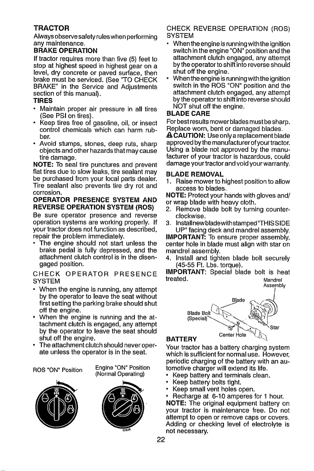
ROS "ON" Position
Engine "ON" Position
(Normal Operating)
CHECK REVERSE OPERATION (ROS)
SYSTEM
• When the engine is runningwiththe ignition
switch in the engine "ON" position and the
attachment clutch engaged, any attempt
by the operator to shift into reverse should
shut off the engine.
- Whenthe engine is runningwith the ignition
switch in the ROS "ON" position and the
attachment clutch engaged, any attempt
by the operator to shift into reverse should
NOT shut off the engine.
BLADE CARE
For best results mower blades must be sharp.
eplace worn, bent or damaged blades.
CAUTION: Use only a replacement blade
approved by the manufacturer of your tractor.
Using a blade not approved by the manu-
facturer of your tractor is hazardous, could
damage your tractor and void your warranty.
BLADE REMOVAL
1. Raise mowerto highest position to allow
access to blades_
NOTE: Protect your hands with gloves and/
or wrap blade with heavy cloth.
2. Remove blade bolt by turning counter-
clockwise.
3. Installnewbladewithstamped"THISSIDE
UP" facing deck and mandrel assembly°
IMPORTANT: To ensure proper assembly,
center hole in blade must align with star on
mandrel assembly.
4. Install and tighten blade bolt securely
(45_55 Ft. Lbso torque).
IMPORTANT: Special blade bolt is heat
treated° Mandrel
Assembly
Blade
(Spec_al)_
Center Hole
BATTERY
Your tractor has a batter/charging system
which is sufficient for normal use. However,
periodic charging of the battery with an au-
tomotive charger will extend its life,
° Keep battery and terminals clean.
• Keep battery bolts tight.
° Keep small vent holes open.
° Recharge at 6-10 amperes for 1 hour.
NOTE =The original equipment battery on
your tractor is maintenance free, Do not
attempt to open or remove caps or covers,
Adding or checking level of electrolyte is
not necessary.
22
TOCLEANBATTERYAND TERMINALS
Corrosionanddirt onthe batteryandtermi-
nalscan causethe batteryto "leak"power.
1, Removeterminalguard,
2. DisconnectBLACK battery cable first
then RED battery cable and remove
batteryfrom tractor°
3, Rinsethebatterywithplainwateranddr,/.
4, Cleanterminalsandbatterycableends
with wire brushuntilbright.
5, Coatterminalswithgreaseor petroleum
jelly.
6, Reinstall battery (See "REPLACING
BATTERY"in the SERVICEAND AD-
JUSTMENTSsectionofthis manual),
TRANSAXLE MAINTENANCE
The transmission fan and cooling fins should
be kept clean to assure proper cooling_ Do
not attempt to clean fan or transmission while
engine is running or while the transmission
is hot. To prevent possible damage to seals,
do not use high pressure water or steam to
clean transaxle.
• Inspect cooling fan to be sure fan blades
are intact and clean,
, inspect cooling fins for dirt, grass clippings
and other materials_ To prevent damage to
seals, do not use compressed air or high
pressure sprayer to clean cooling fins.
TRANSAXLE PUMP FLUID
The transaxle was sealed at the factory and
fluid maintenance is not required for the life
of the transaxle. Should the transaxle ever
leak or require servicing, contact your near-
est Sears or other qualified service center.
V-BELTS
Check V-belts for deterioration and wear after
100 hours of operation and replace if neces-
saryo The belts are not adjustable° Replace
belts if they begin to slip from wear.
ENGINE
LUBRICATION
Only use high quality detergent oil rated with
API service classification SG-SL. Select the
oi!'s SAE viscosity grade according to your
expected operating temperature.
SAE VISCOSITY GRADES
o2 4o _ _0 _i_
...... _MP ERAt_RE' RAN'{_'E"A"NTiC[PATF-D BEFOR E NEXT OIL CHA NGE
NOTE: Although multi-viscosity oils (5W30,
10W30 etc,) improve starting in cold weather,
they will result in increased oil consumption
when used above 32°E Check your engine
oil level more frequently to avoid possible
engine damage from running low on oil,
Change the oil after every 50 hours of opera-
tion or at least once a year if the tractor is
not used for 50 hours in one year.
Checkthe crankcase oil level before starting
the engine and after each eight (8) hours
of operation, Tighten oil fitl cap!dipstick
securely each time you check the oil level.
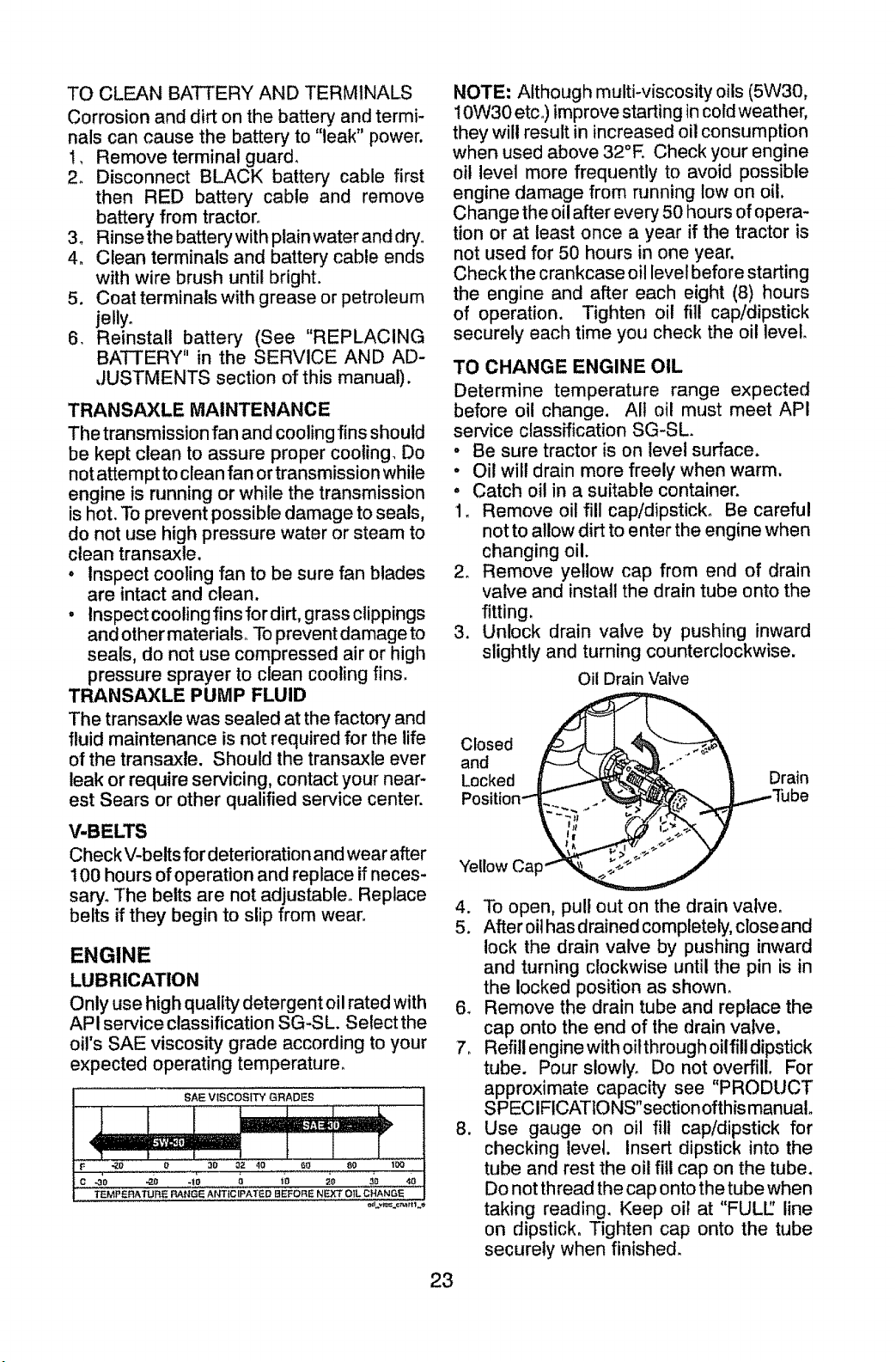
TO CHANGE ENGINE OIL
Determine temperature range expected
before oil change. All oil must meet API
service classification SG-SL.
• Be sure tractor is on level surface.
• Oil will drain more freely when warm.
• Catch oil in a suitable container.
1, Remove oil fill cap/dipstick, Be careful
not to allow dirt to enter the engine when
changing oil.
2_ Remove yellow cap from end of drain
valve and install the drain tube onto the
fitting,
3. Unlock drain valve by pushing inward
slightly and turning counterclockwise.
Closed
and
Locked
Yellow
Oil Drain Valve
Drain
Tube
4. To open, pull out on the drain valve.
5. After oil has drained completely, close and
lock the drain valve by pushing inward
and turning clockwise until the pin is in
the locked position as shown.
6o Remove the drain tube and replace the
cap onto the end of the drain valve,
7. Refill engine with oitthrough oilfill dipstick
tube. Pour slowly. Do not overfill. For
approximate capacity see "PRODUCT
SPECIFICATlONS"sectionofthis manuat°
8. Use gauge on oil fill cap/dipstick for
checking level. Insert dipstick into the
tube and rest the oil fill cap on the tube.
Do not thread the cap onto the tube when
taking reading. Keep oil at "FULL_ line
on dipstick. Tighten cap onto the tube
securely when finished.
23
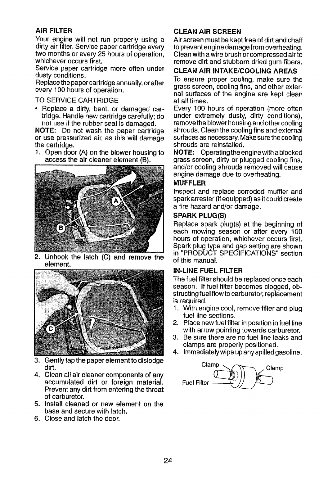
AIR FILTER
Your engine will not run properly using a
dirty air filter. Service paper cartridge every
two months or every 25 hours of operation,
whichever occurs first.
Service paper cartridge more often under
dusty conditions_
Replace the paper cartridge annually, or after
every 100 hours of operation.
TO SERVICE CARTRIDGE
° Replace a dirty, bent, or damaged car-
tridge. Handle new cartridge carefully; do
not use if the rubber seal is damaged.
NOTE: Do not wash the paper cartridge
or use pressurized air, as this will damage
the cartridge.
1o Open door (A) on the blower housing lo
access the air cleaner element (B).
2. Unhook the latch (C) and remove the
element.
3. Gently tap the paper element to dislodge
dirt.
4. Clean all air cleaner components of any
accumulated dirt or foreign material.
Prevent any dirt from entering the throat
of carburetor.
5. Install cleaned or new element on the
base and secure with latch.
6. Close and latch the door.
CLEAN AIR SCREEN
Air screen must be kept free of dirt and chaff
to prevent engine damage from overheating,
Clean with a wire brush or compressed air to
remove dirt and stubborn dried gum fibers.
CLEAN AIR INTAKE/COOLING AREAS
To ensure proper cooling, make sure the
grass screen, cooling fins, and other exter-
nal surfaces of the engine are kept clean
at at! times.
Every 100 hours of operation (more often
under extremely dusty', dirty conditions),
remove the blower housing and other cooling
shrouds. Clean the cooling fins and external
surfaces as necessary. Make sure the cooling
shrouds are reinstalled.
NOTE: Operating the enginewith a blocked
grass screen, dirty or plugged cooling fins,
and/or cooling shrouds removed will cause
engine damage due to overheating.
MUFFLER
Inspect and replace corroded muffler and
spark arrester (if equipped) as it could create
a fire hazard and/or damage.
SPARK PLUG(S)
Replace spark plug(s) at the beginning of
each mowing season or after every t00
hours of operation, whichever occurs first.
Spark plug type and gap setting are shown
in "PRODUCT SPECIFICATIONS" section
of this manual.
IN-LINE FUEL FILTER
The fuel filter should be replaced once each
season, If fuel filter becomes clogged, ob-
structing fuel flow tocarburetor, replacement
is required.
1. With engine cool, remove filter and plug
fuel line sections_
2, Place new fuel filter inposition infuel line
with arrow pointing towards carburetor.
3, Be sure there are no fuel line leaks and
clamps are properly positioned°
4, lmmediatelywipe up anyspitled gasoline,
Clam_mp
Fuel Filter
24
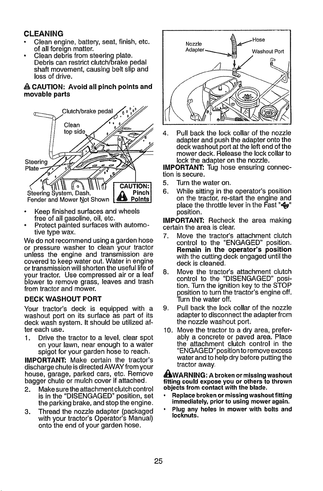
CLEANING
o Clean engine, batter]/, seat, finish, etc.
of all foreign matter.
• Clean debris from steering plate_
Debris can restrict clutch/brake pedal
shaft movement, causing belt shp and
loss of drive.
A CAUTION: Avoid all pinch points and
movable parts
Nozzle _Hose
Adapter -....___ Washout Port
CAUTION: I
Steering System, Dash, A{_ Pinch !
Fender and Mower N_otShown R:_ Points !
, Keep finished surfaces and wheels
free of all gasoline, oil, etc.
° Protect painted surfaces with automo-
tive type wax.
We do not recommend using a garden hose
or pressure washer to clean your tractor
unless the engine and transmission are
covered to keep water out° W./ater in engine
or transmission will shorten the useful life of
your tractor. Use compressed air or a leaf
blower to remove grass, leaves and trash
from tractor and mower.
DECK WASHOUT PORT
Your tractor's deck is equipped with a
washout port on its surface as part of its
deck wash system, it should be utilized af-
ter each use.
1. Drive the tractor to a level, clear spot
on your lawn, near enough to a water
spigot for your garden hose to reach.
IMPORTANT: Make certain the tractor's
discharge chute is directed AWAY from your
house, garage, parked cars, etc. Remove
bagger chute or mulch cover if attached.
2. Make sure the attachment clutch control
is in the "DISENGAGED" position, set
the parking brake, and stop the engine_
3. Thread the nozzle adapter (packaged
with your tractor's Operator's Manual)
onto the end of your garden hose.
4o Pull back the lock collar of the nozzle
adapter and push the adapter onto the
deck washout port at the left end of the
mower deck° Release the lock collar to
lock the adapter on the no771e.
IMPORTANT: Tug hose ensuring connec-
tion is secure.
5. Turn the water on.
6o While sitting in the operator's position
on the tractor, re-start the engine and
place the throttle lever in the Fast ",_"
position.
IMPORTANT: Recheck the area making
certain the area is clear.
7. Move the tractor's attachment clutch
control to the "ENGAGED" position°
Remain in the operator's position
with the cutting deck engaged until the
deck is cleaned.
8. Move the tractor's attachment clutch
control to the "DISENGAGED" posi-
tion. Turn the ignition key to the STOP
position to turn the tractor's engine off.
Turn the water off.
9. Pull back the lock collar of the nozzle
adapter to disconnect the adapter from
the nozzle washout port.
10. Move the tractor to a dry area, prefer-
ably a concrete or paved area. Place
the attachment clutch control in the
"ENGAGED" position to remove excess
water and to help dry before putting the
tractor away.
_IbWARNING: A broken or missing washout
fitting could expose you or others to thrown
objects from contact with the blade.
• Replace broken or missing washout fitting
immediately, prior to using mower again.
• Plug any holes in mower with bolts and
Iocknuts.
25
_ ARNING: TO AVOID SERIOUS INJURY, BEFORE PERFORMING ANY SERVICE OR
ADJUSTMENTS:
and set
3 Depress clutch/brake pedal fully parking brake.
o Place attachment clutch in "DISENGAGED" position°
4. Turn ignition key to "STOP" and remove key.
5o Make sure the blades and all moving parts have completely stopped.
6. Disconnect spark plug wire from spark plug and place wire where it cannot come
in contact with plug.
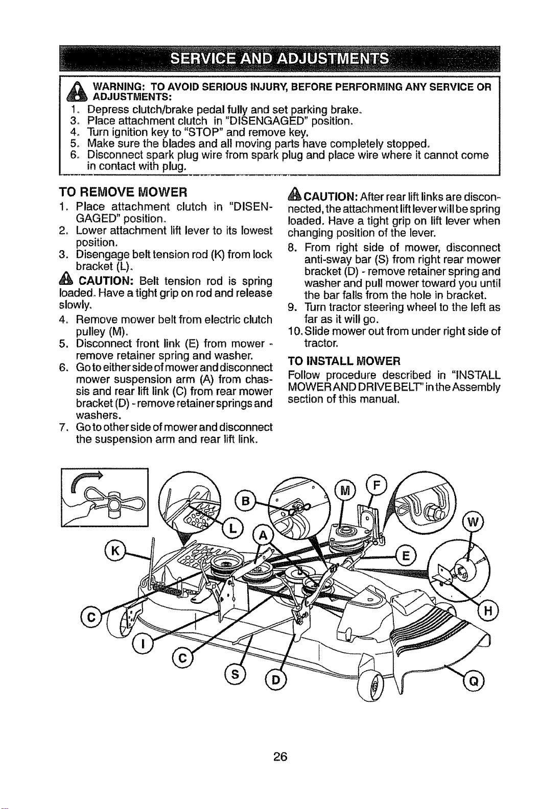
TO REMOVE MOWER
1. Place attachment clutch in "DISEN-
GAGED" position.
2o Lower attachment lift lever to its lowest
position.
3. Disengage belt tension rod (K) from lock
bracket (L)_
CAUTION: Belt tension rod is spring
loaded° Have a tight grip on rod and release
slowly°
4. Remove mower belt from electric clutch
pulley (M).
5. Disconnect front link (E) from mower
remove retainer spring and washer.
6. Go to either side of mower and disconnect
mower suspension arm (A) from chas-
sis and rear lift link (C) from rear mower
bracket (D) - remove retainer springs and
washers.
7. Go to other side of mower and disconnect
the suspension arm and rear lift link.
CAUTION: After rear lift links are discon-
nected, the attachment lift lever will be spring
loaded. Have a tight grip on lift lever when
changing position of the lever.
8. From right side of mower, disconnect
anti-sway bar (S) from right rear mower
bracket (D) - remove retainer spring and
washer and pull mower toward you until
the bar fails from the hole in bracket.
9. Turn tractor steering wheel to the left as
far as it will go.
10.Slide mower out from under right side of
tractor.
TO INSTALL MOWER
Follow procedure described in "INSTALL
MOWER AND DRIVE BELT"intheAssembly
section of this manual.
26
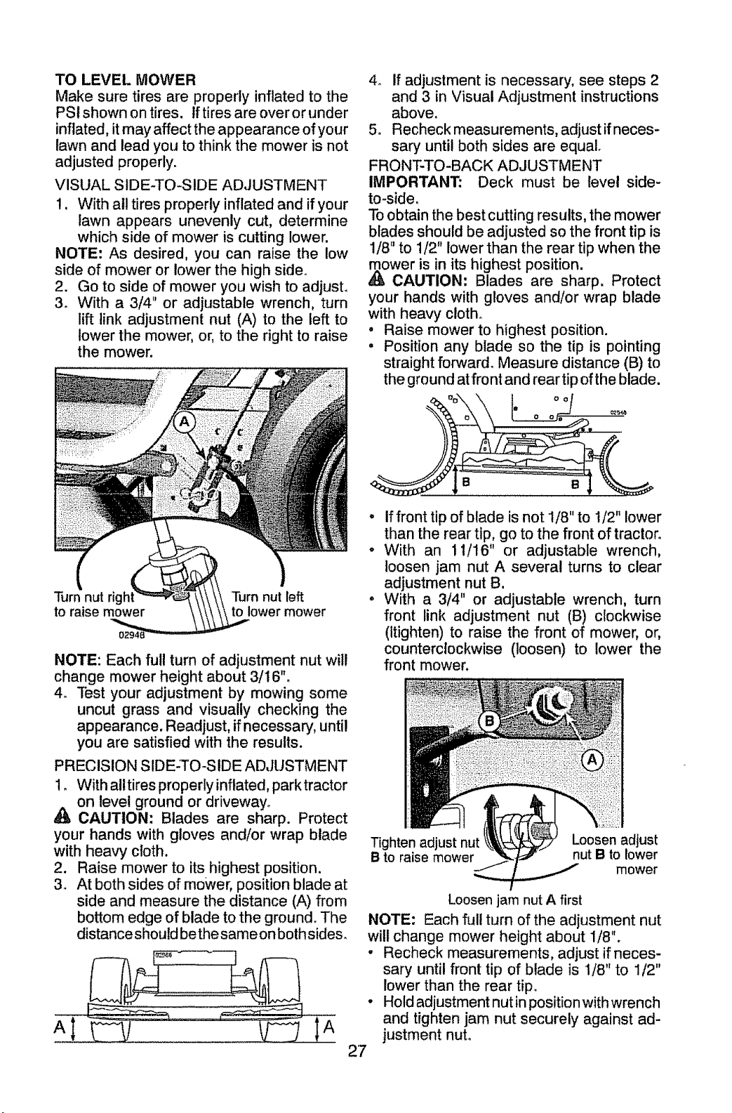
TO LEVEL MOWER
Make sure tires are properly inflated to the
PSi shown on tires. If tires are over or under
inflated, it may affect the appearance of your
lawn and lead you to think the mower is not
adjusted properly.
VISUAL SIDE-TO-SIDE ADJUSTMENT
!. With all tires properly inflated and if your
lawn appears unevenly cut, determine
which side of mower is cutting lower.
NOTE: As desired, you can raise the low
side of mower or lower the high side°
2. Go to side of mower you wish to adjust.
3. With a 3/4" or adjustable wrench, turn
lift link adjustment nut (A) to the left to
lower the mower, or, to the right to raise
the mower.
Turn nut rigi
to raise mower
Turn nut left
to lower mower
NOTE: Each ful! turn of adjustment nut will
change mower height about 3/16".
4_ Test your adjustment by mowing some
uncut grass and visually checking the
appearance. Readjust, if necessary, until
you are satisfied with the results.
PRECISION SIDE-TO-SIDE ADJUSTMENT
1. With alltires properly inflated, park tractor
on level ground or driveway°
CAUTION: Blades are sharp. Protect
your hands with gloves and/or wrap blade
with heavy cloth.
2. Raise mower to its highest position.
3_ At both sides of mower, position blade at
side and measure the distance (A) from
bottom edge of blade to the ground. The
distance should be the same on both sides.
I A
4o if adjustment is necessary, see steps 2
and 3 in Visual Adjustment instructions
above.
5o Recheck measurements, adjust if neces-
sary until both sides are equal.
FRONT-TO-BACK ADJUSTMENT
IMPORTANT: Deck must be level side-
to-side,
To obtain the best cutting results, the mower
blades should be adjusted so the front tip is
1/8" to 1/2" lower than the rear tip when the
,_ower is in its highest position.
CAUTION: Blades are sharp. Protect
your hands with gloves and/or wrap blade
with heavy cloth°
• Raise mower to highest position.
• Position any blade so the tip is pointing
straight forward. Measure distance (B) to
the ground at front and rear tip of the blade.
° if front tip of blade is not 1/8" to 1/2" lower
than the rear tip, go to the front of tractor.
• With an 11/16" or adjustable wrench,
loosen jam nut A several turns to clear
adjustment nut B.
• With a 3/4" or adjustable wrench, turn
front link adjustment nut (B) clockwise
(itighten) to raise the front of mower, or,
counterclockwise (loosen) to lower the
front mower.
Tighten adjust nut
B to raise mower
Loosen adjust
nut B to lower
mower
Loosen jam nut A first
NOTE: Each full turn of the adjustment nut
wilt change mower height about 1/8".
° Recheck measurements, adjust if neces-
sary until front tip of blade is 1/8" to 1/2"
lower than the rear tip.
, Hold adjustment nut in position with wrench
and tighten jam nut securely against ad-
justment nut.
27
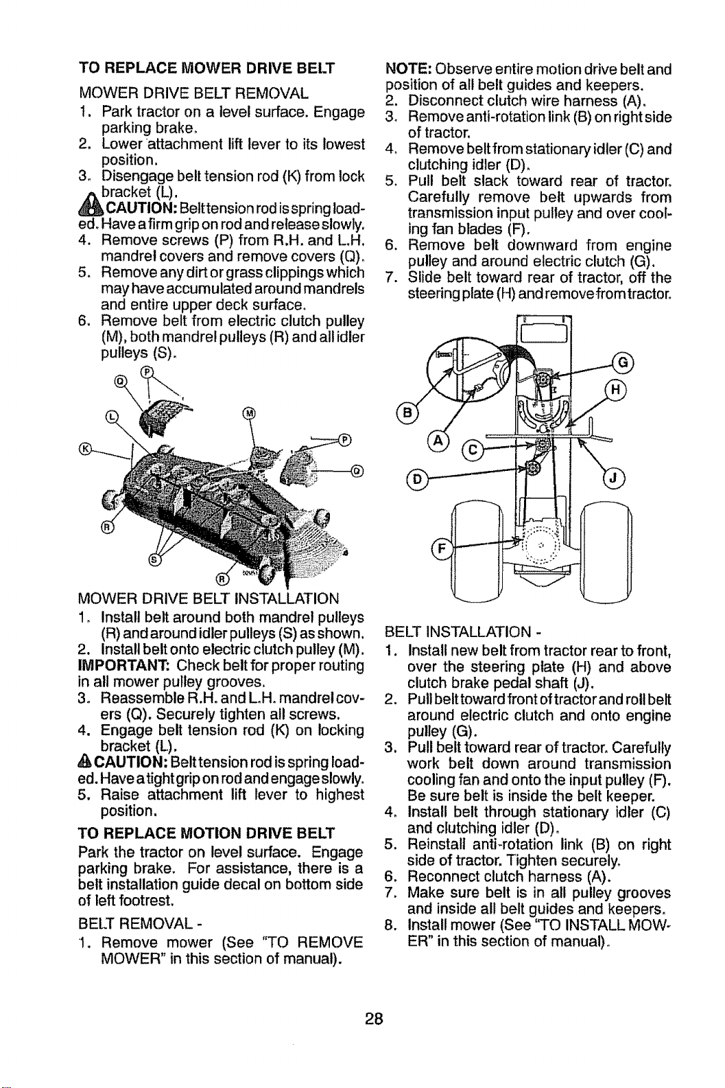
TO REPLACE MOWER DRIVE BELT
MOWER DRIVE BELT REMOVAL
I. Park tractor on a level surface. Engage
parking brake_
2. Lower attachment lift lever to its lowest
position.
3o Disengage belt tension rod (K) from lock
bracket (L).
AUTION: Belttension rod is spring load-
edo Have a firm grip on rod and release slowly.
4. Remove screws (P) from R.H. and L.H.
mandrel covers and remove covers (Q),
5, Remove any dirt or grass clippings which
may have accumulated around mandrels
and entire upper deck surface°
6, Remove belt from electric clutch pulley
(M), both mandrel pulleys (R) and all idler
pulleys (S).
NOTE =Observe entire motion drive belt and
position of all belt guides and keepers.
2. Disconnect clutch wire harness (A).
3_ Remove anti-rotation link (B) on right side
of tractor.
4. Remove beltfrom stationary idler (C) and
clutching idler (D),
5. Pull belt slack toward rear of tractor.
Carefully remove belt upwards from
transmission input pulley and over cool-
ing fan blades (F).
6. Remove belt downward from engine
pulley and around electric clutch (G).
7. Slide belt toward rear of tractor, off the
steering plate (H) and remove from tractor.
__._..j=
i
MOWER DRIVE BELT INSTALLATION
!. Install belt around both mandrel pulleys
(R) and around idler pulleys (S) as shown.
2, Install belt onto electric clutch pulley (M).
IMPORTANT; Check belt for proper routing
in all mower pulley grooves,
3, Reassemble R.Ho and L.H_ mandrelcov-
ers (Q), Securely tighten all screws,
4. Engage belt tension rod (K) on locking
A bracket (L).
CAUTION; Belt tension rod is spring load-
ed. Have atight grip on rod and engage slowly.
5. Raise attachment lift lever to highest
position.
TO REPLACE MOTION DRIVE BELT
Park the tractor on level surface. Engage
parking brake. For assistance, there is a
belt installation guide decal on bottom side
of left footrest.
BELT REMOVAL-
i. Remove mower (See "TO REMOVE
MOWER" in this section of manual).
BELT INSTALLATION -
1. Install new belt from tractor rear to front,
over the steering plate (H) and above
clutch brake pedal shaft (J).
2. Pull beittowardfront oftractorand roll belt
around electric clutch and onto engine
pulley (G).
3. Pull belt toward rear of tractor, Carefully
work belt down around transmission
cooling fan and onto the input pulley (F).
Be sure belt is inside the belt keeper.
4. Install belt through stationary idler (C)
and clutching idler (D) o
5. Reinstall anti-rotation link (B) on right
side of tractor. Tighten securely.
6. Reconnect clutch harness (A).
7. Make sure belt is in all pulley grooves
and inside all belt guides and keepers.
8. Install mower (See 'qO INSTALL MOW-
ER" in this section of manual).
28
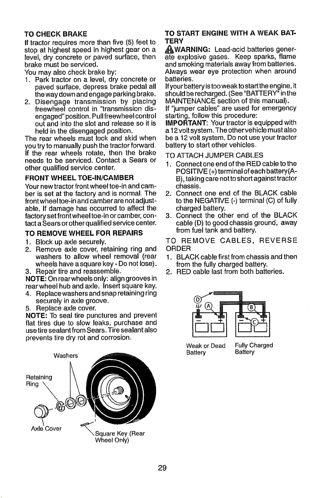
TO CHECK BRAKE
If tractor requires more than five (5) feet to
stop at highest speed in highest gear on a
level, dr,/concrete or paved surface, then
brake must be serviced.
You may also check brake by:
1. Park tractor on a level, dry concrete or
paved surface, depress brake pedal all
the way down and engage parking brake.
2. Disengage transmission by placing
freewheel control in "transmission dis-
engaged" position. Pull freewheel control
out and into the slot and release so it is
held in the disengaged position.
The rear wheels must lock and skid when
you try to manually push the tractor forward.
If the rear wheels rotate, then the brake
needs to be serviced. Contact a Sears or
other qualified service center.
FRONT WHEEL TOE-IN/CAMBER
Your new tractor front wheel toe-in and cam-
ber is set at the factory and is normal. The
front wheel toe-in and camber are not adjust-
able. If damage has occurred to affect the
factory set front wheel toe-in or camber, con-
tact a Sears or other qualified service center.
TO REMOVE WHEEL FOR REPAIRS
1o Block up axle securely.
2. Remove axle cover, retaining ring and
washers to allow wheel removal (rear
wheels have a square key - Do not lose).
3. Repair tire and reassemble.
NOTE: On rear wheels only: align grooves in
rear wheel hub and axle. Insert square key.
4. Replace washers and snap retaining ring
securely in axle groove.
5. Replace axle cover.
NOTE: To seal tire punctures and prevent
flat tires due to slow leaks, purchase and
use tire sealant from Sears° Tire sealant also
prevents tire dry rot and corrosion.
Washers
TO START ENGINE WITH A WEAK BAT-
TERY
_WARNING: Lead-acid batteries gener-
ate explosive gases. Keep sparks, flame
and smoking materials away from batteries.
Always wear eye protection when around
batteries.
tf your battery is too weak to start the engine, it
should be recharged, (See "BATTERY" in the
MAINTENANCE section of this manual).
If "jumper cables" are used for emergency
starting, follow this procedure:
IMPORTANT: Your tractor is equipped with
a 12 volt system. The othervehicle must also
be a 12 volt system. Do not use your tractor
battery to start other vehicles_
TO ATTACH JUMPER CABLES
!. Connect one end of the RED cable to the
POSITIVE (+) terminal of each battery(A-
B), taking care not to short against tractor
chassis.
2. Connect one end of the BLACK cable
to the NEGATIVE (-) terminal (C) of fully
charged batter,/.
3. Connect the other end of the BLACK
cable (D) to good chassis ground, away
from fuel tank and battery.
TO REMOVE CABLES, REVERSE
ORDER
1, BLACK cable first from chassis and then
from the fully charged battery.
2. RED cable last from both batteries.
Weak or Dead Fully Charged
Battery Battery
Retaining
Ring _,.
Axle Cover
!
_Square Key (Rear
Wheel Only)
29
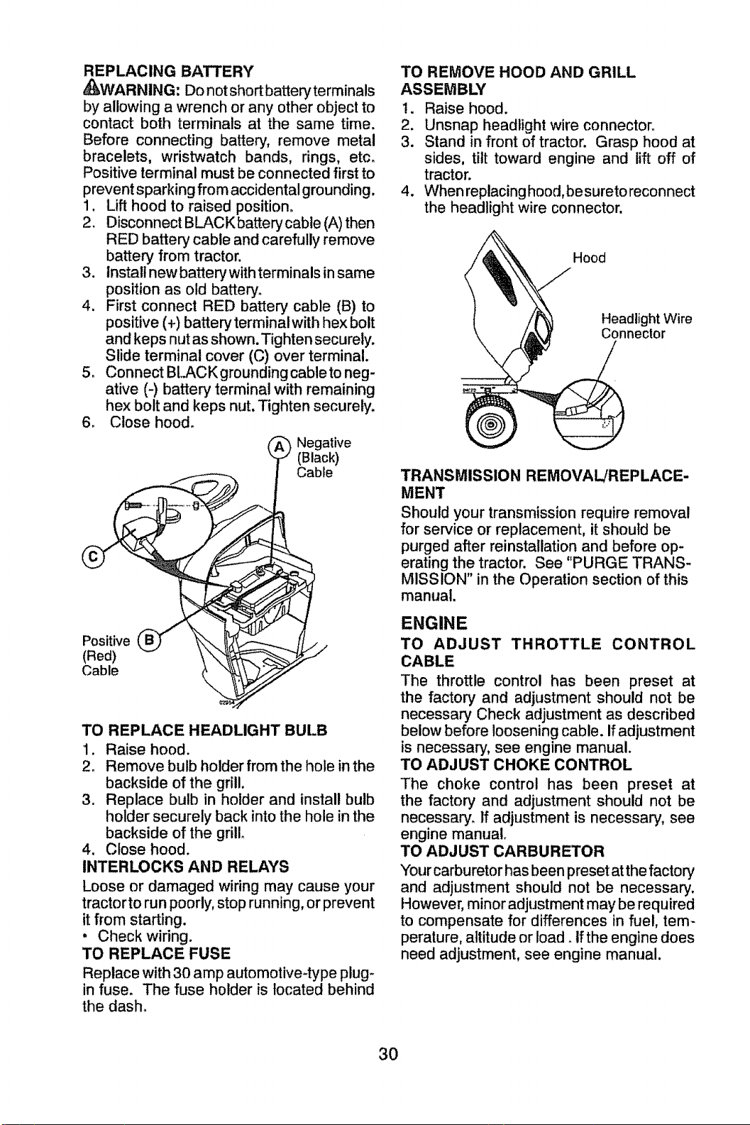
REPLACING BATTERY
,_WARNING: Do not short batteryterminals
by allowing a wrench or any other object to
contact both terminals at the same time.
Before connecting battery, remove metal
bracelets, wristwatch bands, rings, etc.
Positive terminal must be connected first to
prevent sparking from accidental grounding.
1.
2.
3,
4_
5_
6_
Lift hood to raised position.
Disconnect BLACK battery cable (A) then
RED battery cable and carefully remove
battery from tractor.
install new battery with terminals in same
position as old battery.
First connect RED battery cable (B) to
positive (+) battery terminalwith hex bolt
and keps nut as shown. Tighten securely.
Slide terminal cover (C) over terminal.
Connect BLACK grounding cable to neg-
ative (-) battery terminal with remaining
hex bolt and keps nut, Tighten securely.
Close hood.
_. _ Negative
(Black)
Cable
Positive
(Red)
Cable
TO REPLACE HEADLIGHT BULB
1. Raise hood.
2. Remove bulb holder from the hole in the
backside of the grill.
3. Replace bulb in holder and install bulb
holder securely back intothe hole inthe
backside of the grill,
4. Close hood.
INTERLOCKS AND RELAYS
Loose or damaged wiring may cause your
tractor to run poorly,stop running,orprevent
it from starting.
• Check wiring.
TO REPLACE FUSE
Replace with30 amp automotive-type plug-
in fuse. The fuse holder is located behind
the dash.
TO REMOVE HOOD AND GRILL
ASSEMBLY
!. Raise hood.
2. Unsnap headlight wire connector.
3. Stand in front of tractor. Grasp hood at
sides, tilt toward engine and lift off of
tractor.
4. When replacing hood, be sureto reconnect
the headlight wire connector.
Hood
Headlight Wire
Connector
TRANSMISSION REMOVAL/REPLACE-
MENT
Should your transmission require removal
for service or replacement, it should be
purged after reinstatlation and before op-
erating the tractor. See "PURGE TRANS-
MISSION" in the Operation section of this
manual.
ENGINE
TO ADJUST THROTTLE CONTROL
CABLE
The throttle control has been preset at
the factory and adjustment should not be
necessary Check adjustment as described
below before loosening cable. If adjustment
is necessary, see engine manual.
TO ADJUST CHOKE CONTROL
The choke control has been preset at
the factory and adjustment should not be
necessary. If adjustment is necessary, see
engine manual.
TO ADJUST CARBURETOR
Your carburetor has been preset at the factory
and adjustment should not be necessary.
However, minor adjustment may be required
to compensate for differences in fuel, tem-
perature, altitude or load. If the engine does
need adjustment, see engine manual.
3O
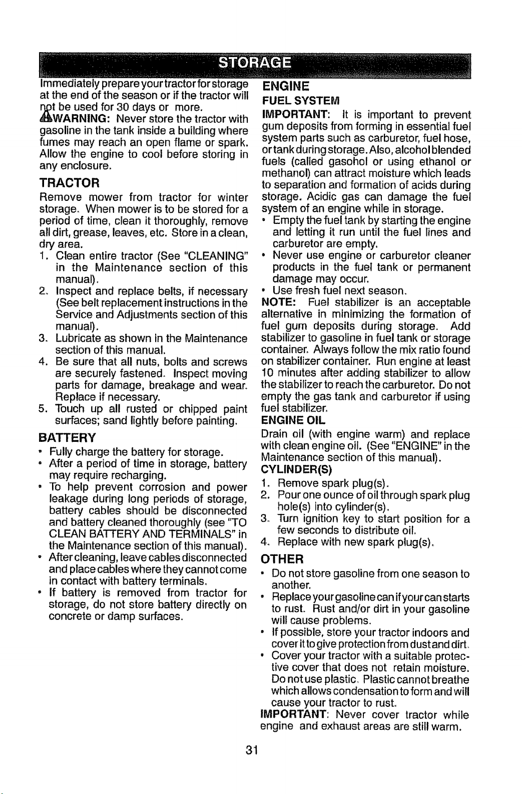
Immediately prepare your tractor for storage
at the end of the season or if the tractor will
tbe used for 30 days or more.
WARNING: Never store the tractor with
gasoline in the tank inside a building where
fumes may reach an open flame or spark.
Allow the engine to cool before storing in
any enclosure_
TRACTOR
Remove mower from tractor for winter
storage. When mower is to be stored for a
period of time, clean it thoroughly, remove
all dirt, grease, leaves, etc. Store in a clean,
dry area.
1. Clean entire tractor (See "CLEANING"
in the Maintenance section of this
manual).
2_ Inspect and replace belts, if necessary
(See belt replacement instructions in the
Service and Adjustments section of this
manual).
3. Lubricate as shown in the Maintenance
section of this manual,
4. Be sure that all nuts, bolts and screws
are securely fastened, inspect moving
parts for damage, breakage and wear.
Replace if necessary_
5. Touch up all rusted or chipped paint
surfaces; sand lightly before painting.
BATTERY
- Fully charge the battery for storage.
• After a period of time in storage, battery
may require recharging.
, To help prevent corrosion and power
leakage during long periods of storage,
battery cables should be disconnected
and battery cleaned thoroughly (see "TO
CLEAN BATTERY AND TERMINALS" in
the Maintenance section of this manual).
o Aftercteaning, leave cables disconnected
and place cables where they cannot come
in contact with battery terminals.
• if battery is removed from tractor for
storage, do not store battery directly on
concrete or damp surfaces.
ENGINE
FUEL SYSTEM
IMPORTANT: It is important to prevent
gum deposits from forming in essential fuel
system parts such as carburetor, fuel hose,
or tank during storage. Also, alcohol blended
fuels (called gasohol or using ethanol or
methanol) can attract moisture which leads
to separation and formation of acids during
storage. Acidic gas can damage the fuel
system of an engine while in storage.
, Empty the fuel tank by starting the engine
and letting it run until the fuel lines and
carburetor are empty,
, Never use engine or carburetor cleaner
products in the fuel tank or permanent
damage may occur.
° Use fresh fuel next season.
NOTE: Fuel stabilizer is an acceptable
alternative in minimizing the formation of
fuel gum deposits during storage. Add
stabilizer to gasoline in fuel tank or storage
container. Always follow the mix ratio found
on stabilizer container. Run engine at least
10 minutes after adding stabilizer to allow
the stabilizer to reach the carburetor. Do not
empty the gas tank and carburetor if using
fuel stabilizer.
ENGINE OIL
Drain oil (with engine warm) and replace
with clean engine oil. (See "ENGINE" in the
Maintenance section of this manual).
CYLINDER(S)
1. Remove spark plug(s).
2. Pour one ounce of oil through spark plug
hole(s) into cylinder(s).
3o Turn ignition key to start position for a
few seconds to distribute oil.
4. Replace with new spark plug(s).
OTHER
* Do not store gasoline from one season to
another.
, Replaceyourgasolinecanifyourcanstarts
to rust. Rust and/or dirt in your gasoline
will cause problems.
° If possible, store your tractor indoors and
cover it to give protection from dust and dirt_
° Cover your tractor with a suitable protec-
tive cover that does not retain moisture.
Do not use plastic. Plastic cannot breathe
which allows condensation to form and will
cause your tractor to rust°
IMPORTANT: Never cover tractor while
engine and exhaust areas are still warm.
31
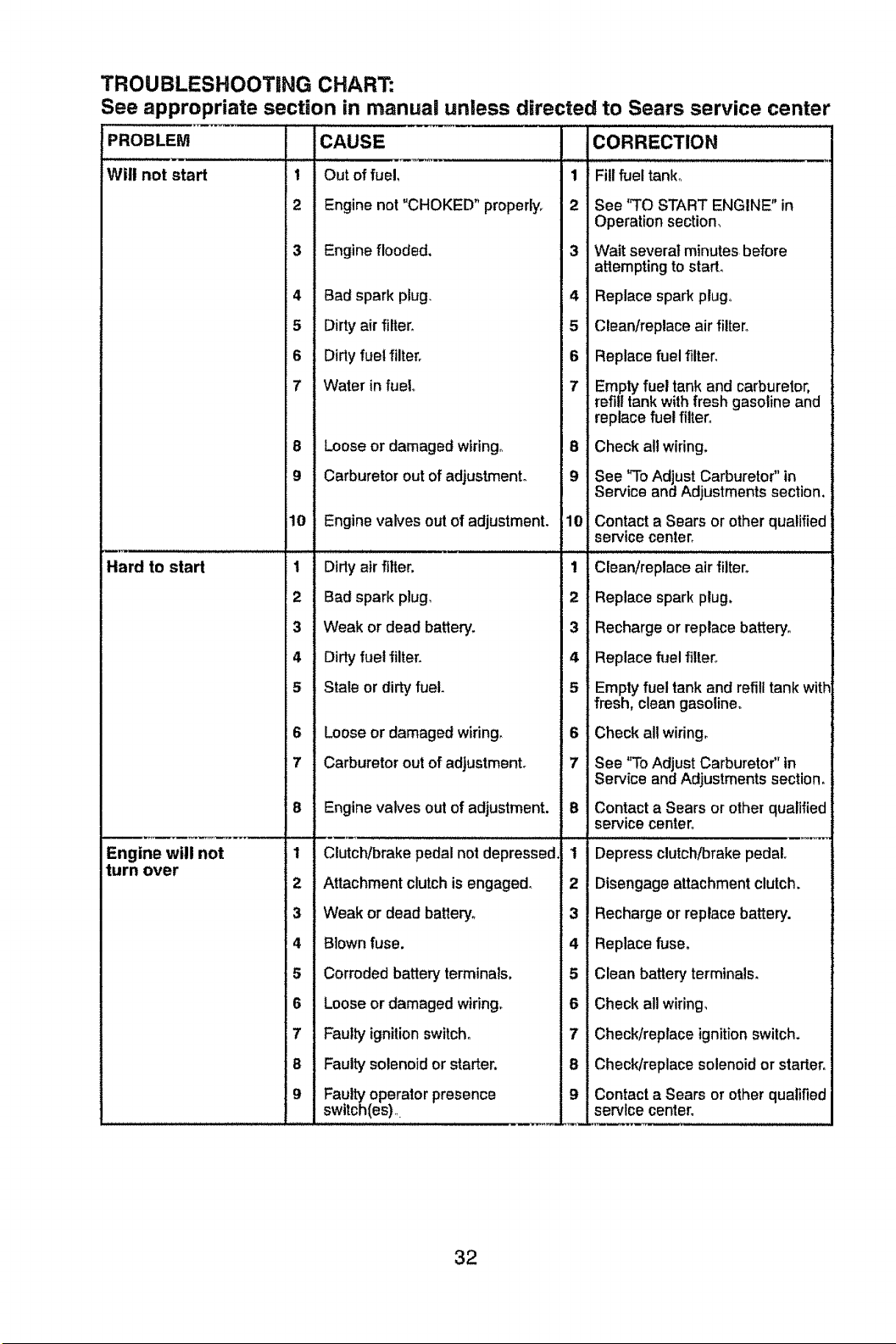
TROUBLESHOOTING CHART:
See appropriate section in manual unless directed to Sears service center
PROBLEM CAU SE CORRECTION
Wilt not start 1 Out cf fuel, 1 Fill fuel tank,,
2 Engil te not "CHOKED" prolcerly. 2 See "TO START ENGINE" in
Operation section,
3 Engil_e flooded. 3 Wait several minutes before
attempting to start.
4 Bad .,;park plug. 4 Replace spark plugo
5 Dirty air filter. 5 Clean/replace air filter°
6 Dirty fuel filter. 6 Replace fuel filter,
7 Water in fuel. 7 Empty fuel tank and carburetor,
refill tank with fresh gasoline and
replace fuel filter_
8 Loos ._or damaged wiring° 8 Check all wiring.
9 Carb _retor out of adjustme_ _L 9 See "To Adjust Carburetor" in
Service and Adjustments section.
jlO EngiF_e valves out of adjust nent. 10 Contact a Sears or other qualified
service center.
Hard to start
Engine will not
turn over
1 Dilly air filter.
2 Bad ,;park plug.
3 Weal: or dead battery.
4 Dirty fuel filter.
5 Stale or dirty fuel.
6 Loos _or damaged wiring,
7 Carb _retorout of adjustmellt.
1 Clean/replace air filter°
2 Replace spark plug.
3 Recharge or replace battery.
4 Replace fuel filter°
5 Empty fuel tank and refill tank with
fresh, clean gasoline°
6 Check all wiring.
7 See "To Adjust Carburetor" in
Service and Adjustments section.
8 Engir_evalves out of adjustinent.
1
2 Attachment clutch is engag
3 Weak or dead battery°
4 Blown fuse.
5 Corroded battery terminals,
Contact a Sears or other qualified
service center.
Depress clutch/brake pedal.
Disengage attachment clutch.
Recharge or replace battery.
Replace fuse.
Clean battery terminals.
6 Loose or damaged wiring.
17 Faulty ignition switch°
8 Faulty solenoid or starter.
9 Faulty operator presence
switch(es).
Check all wiring,
Check/replace ignition switch.
Check/replace solenoid or starter°
Contact a Sears or other qualified
service center°
32
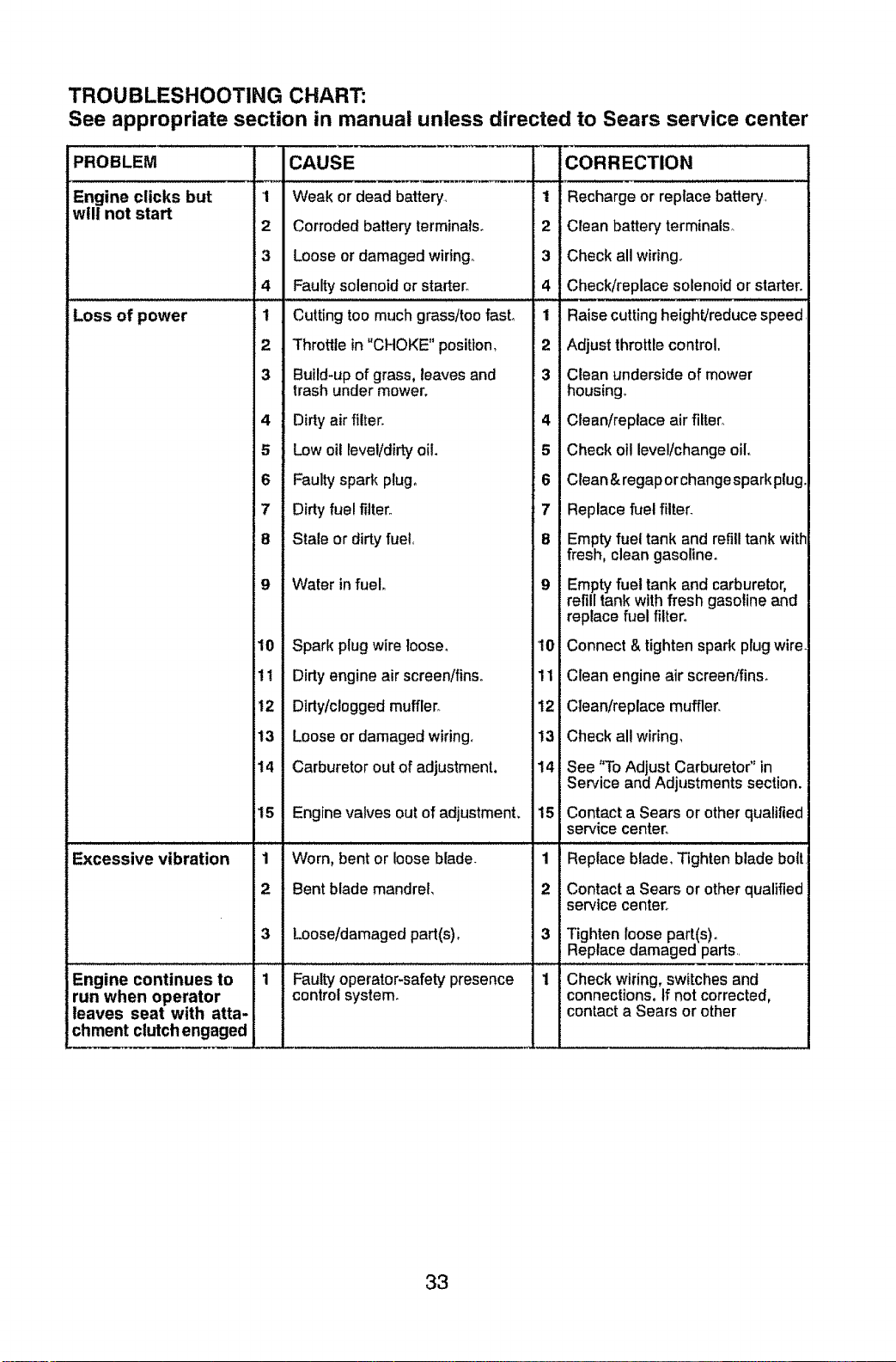
TROUBLESHOOTING CHART:
See appropriate section in manual unless directed to Sears service center
PROBLEM
Engine clicks but
will not start
Loss of power
CAUSE
1 Weak or dead battery,
2 Corroded battery terminals.
3 Loose or damaged wiring_
4 Faulty solenoid or starter.
1 Cutting toe much grass/too fasL
2 Throttle in "CHOKE" position,
CORRECTION
1 Recharge or replace battery,
2 Clean battery terminals_
3 Check all wiring,
4 Check/replace solenoid or starter.
...... ! ! i i
1 Raise cutting height/reducespeed
2 Adjust throttle control.
3 Build*up of grass, leaves and 3 Clean underside of mower
trash under mower, housing.
4 Dirty air filter. 4 Clean/replace air filter_
5 Low oil level/dirty oil. 5 Check otl levellchange oil,
6 Faulty spark plug, 6 Clean®aporchangesparkplug
7 Dirty fuel filter. 7 Replace fuel filter_
8 Stale or dirty fuel, 8 Empty fuel tank and refill tank with
fresh, clean gasoline.
9 Water in fuel. 9 Empty fuel tank and carburetor,
refill tank with fresh gasoline and
replace fuel filter_
i10 Spark plug wire loose, '10 Connect & tighten spark plug wire
il! Dirty engine air screen/fins, 11 Clean engine air screentfins,
it2 Dirty/clogged muffler° 12 Clean/replace muffler_
i13 Loose or damaged wiring, 13 Check al! wiring,
i14
15
,, !! Lll i i i llll ILl !,,
Excessive vibration 1
2
Carburetor out of adjustment. 14 See "To Adjust Carburetor" in
Service and Adjustments section.
Engine valves out of adjustment, 15 Contact a Sears or other qualified
service center°
! • Li i i i ii ,i
Worn, bent or loose blade. 1 Replace blade, Tighten blade bolt
Bent blade mandrel,
2 Contact a Sears or other qualified
service center,,
3 Loose/damaged part(s), 3 Tighten loose part(s)o
Replace damaged parts
i i ..........
Engine continues to I 1 i Faulty operator-safety presence I Check wiring, switches and
run when operator I i control system, connections, tf not corrected,
leaves seat with atta- I I contact a Sears or other
chmenlt clutch engaged i i
33
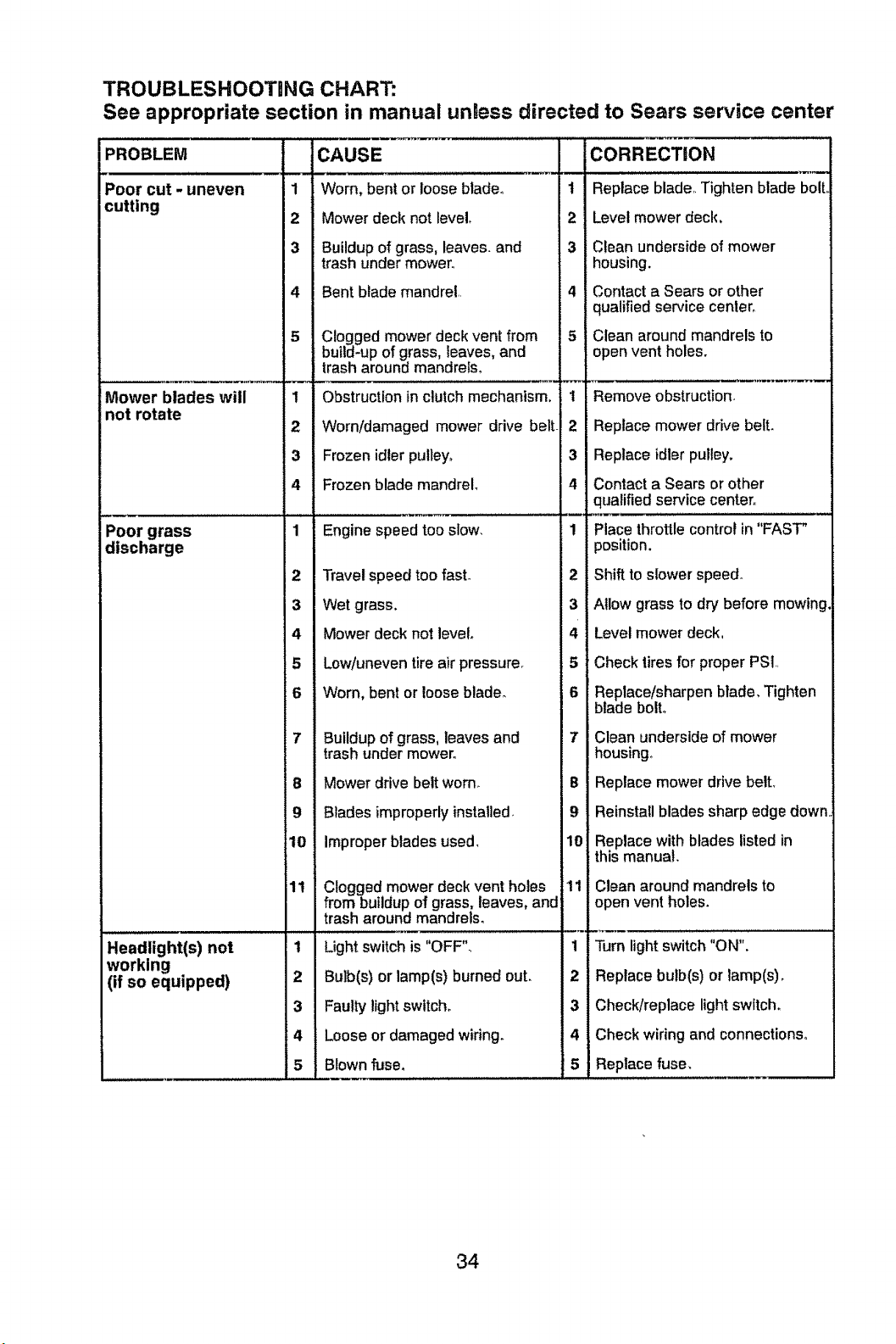
TROUBLESHOOTING CHART:
See appropriate section in manual unless directed to Sears service center
PROBLEM CAUSE
Poor cut - uneven 1 Worn, bent or loose blade°
cutting
2 Mower deck not level,
3 Buildup of grass, leaves, and
trash under mower,,
4 Bent blade mandrel,
Mower blades will
not rotate
Poor grass
discharge
5 Clogged mower deck vent fro
build-up of grass, leaves, and
trash around mandrels,
1 Obstruction in clutch mechan
2 Worn/damaged mower drive belt
3 Frozen idler pulley,
4 Frozen blade mandrel.
1 Engine speed too slow.
2 Travel speed too fast.
3 Wet grass.
4 Mower deck not level.
5 Low/uneven tire air pressurer
6 Worn, bent or loose blade.
7 Buildup of grass, leaves and
trash under mower°
8 Mower drive belt worn.
9 Blades improperly installed.
10 Improper blades used,
Headlight(s) not
working
(if so equipped)
i11 Clogged mower deck vent ho
from buildup of grass, leaves and
trash around mandrels,
1 Light switch is "OFF".
2 Bulb(s) or lamp(s) burned ou!
3 Faulty light switch°
4 Loose or damaged wiring.
5 Blown fuse,
1
2
3
4
5
1
2
3
4
1
2
3
4
5
6
7
B
@
10
11
1
2
3
4
F5
CORRECTION
Replace blade,, Tighten blade bolt
Level mower deck,
Clean underside of mower
housing.
Contact a Sears or other
qualified service center,
Clean around mandrels to
open vent holes.
Remove obstruction-
Replace mower drive belt.
Replace idler pulley.
Contact a Sears or other
qualified service center,,
Place throttle control in "FAST"
position.
Shift to slower speed.
Allow grass to dr), before mowing,
Level mower deck,
Check tires for proper PSI,,
Replace/sharpen blade, Tighten
blade bolto
Clean underside of mower
housing°
Replace mower drive belt,
Reinstall blades sharp edge down.
Replace with blades listed in
this manual.
Clean around mandrels to
open vent holes.
Turn light switch "ON".
Replace bulb(s) or lamp(s),
Check/replace light switch°
Check wiring and connections°
Replace fuse,
34

TROUBLESHOOTING CHART:
See appropriate section in manual unless directed to Sears service center
PROBLEM
Battery will not
charge
Loss of drive
1
2
3
4
1
2
3
4
5
1
1
Engine "backfires"
wnen turnlnq
engine "OFF"
tErng!nedies when
aclor Is shifteo
into reverse
CAUSE
Bad battery cell(s)o
Poor cable connections.
Faulty regulator (if so equipped),
Faulty alternator,
Freewheel control in
"DISENGAGED" position°
Debris on steering plate (if
equipped)_
Motion drive belt worn, damaged,
or broken.
Air trapped in transmission during
shipment or servicing,
Axle key missing.
Engine throttle control not se_
between haft and full speed (fast)::
posilion before stopping engine
Reverse operation system (ROS)
is not "ON" while mower orother
attachment is engaged,
1
2
3
4
1
2
3
4
5
1
1
CORRECTIOhl
Replace battery,
ChecWclean all connections_
Replace regulator,
Replace alternator.
Place freewheel control in
"ENGAGED" position°
See "CLEANING" in the
maintenance section.
Replace motion drive bell
Purge transmission°
Install axle key at rear wheel,, See
"TO REMOVE WHEEL" in the
Service and Adjustments section,
Move throttle control between
half and full speed (fast) position
before stopping engine°
•Jm ignition key to ROS "ON"
position° See Operation section°
NEED MORE HELP?
You'llfindtheanswerandmoreonmanagemyhome.com- for free!
- Find this and all your other product manuaLsonline.
• Get answers from our team of home experts,
• Get a persona!Jzed maintenance plan for your home.
. Find information and tooL_ to help with home projects,
!i;i
35
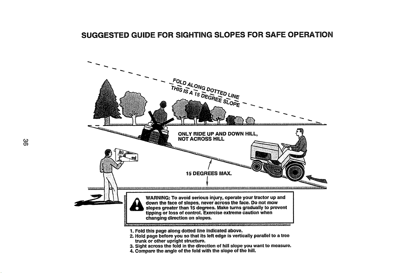
SUGGESTED GUIDE FOR SiGHTiNG SLOPES FOR SAFE OPERATION
Co
O3
ONLY RIDE UP AND DOWN HILL,
NOT ACROSS HILL
15 DEGREES MAX,
WARNING: To avoid serious injury, operate your tractor up and
down the face of slopes, never across the face. Do not mow
slopes greater than 15 degrees. Make turns gradually to prevent
tipping or loss of control. Exercise extreme caution when
changing direction on slopes.
1. Fold this page along dotted line indicated above.
2. Hold page before you so that its left edge is vertically parallel to a tree
trunk or other upright structure.
3. Sight across the fold in the direction of hill slope you want to measure.
4. Compare the angle of the fo!d with the slope of the hill.
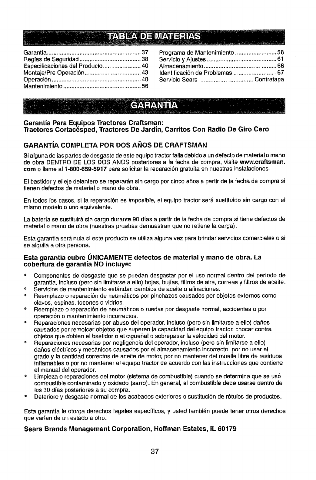
Garantia .......................................................... 37
Reglas de Seguridad ..................................... 38
Especificaciones del Producto ....................... 40
MontajeiPre Operaci6n .................................... 43
Operaci6n ...................................................... 48
Mantenimiento ................................................ 56
Programa de Mantenimiento ......................... 56
Servicio y Ajustes .......................................... 61
Aimacenamiento ............................................. 66
Identificaci6n de Probtemas ..............................67
Servicio Sears .................................. Contratapa
Garantia Para Equipos Tractores Craftsman:
Tractores Cortacesped, Tractores De Jardm, Carritos Con Radio De Giro Cero
GARANTiA COMPLETA POR DOS A_IOS DE CRAFTSMAN
Si alguna de las partes de desgaste de este equipo tractor fatla debido a un defecto de material o mano
de obra DENTRO DE LOS DOS ANOS posteriores a ]a fecha de compra, visite www.craftsman.
corn o Ilame al 1-800-659-5917 para solicitar la reparaci6n gratuita en nuestras instalaciones.
Et bastidor y el eje detantero se reparar_.n sin cargo por cinco a_os a partir de la fecha de compra si
tienen defectos de material o mano de obra_
En todos los casos, si ta reparaci6n es imposible, el equipo tractor ser& sustituido sin cargo con el
mismo modelo o uno equivalente.
La baterta se sustituir& sin cargo durante 90 alias a partir de ta fecha de compra si tiene defectos de
material o mano de obra (nuestras pruebas demuestran que no retiene la carga)_
Esta garantia ser& nula si este producto se utiUza alguna vez para brindar servicios comerciales o si
se alquila a otra persona.
Esta garantia cubre UNICAMENTE defectos de material y mano de obra. La
cobertura de garantla NO incluye:
= Componentes de desgaste que se puedan desgastar por el uso normal dentro del periodo de
garantia, incluso (pero sin limitarse a ello) hojas, bujfas, filtros de aire, correas y filtros de aceite.
o Servicios de mantenimiento est&ndar, cambios de aceite o afinaciones.
= Reemplazo o reparaci6n de neum&ticos por pinchazos causados por objetos externos como
ctavos, espinas, tocones o vidrios.
o Reemplazo o reparaci6n de neum&ticos o ruedas por desgaste normal, accidentes o por
operaciSn o mantenimiento incorrectoso
= Reparaciones necesarias por abuso del operador, incluso (pero sin limitarse a ello) da_os
causados por remolcar objetos que superen la capacidad del equipo tractor, chocar contra
objetos que doblen el bastidor o el cigL_ef_alo sobrepasar la velocidad del motor.
Reparaciones necesarias por negligencia del operador, incluso (pero sin limitarse a ello)
dafios el_ctricos y mec&nicos causados por el almacenamiento incorrecto, por no usar et
grade y la cantidad correctos de aceite de motor, por no mantener det muelle libre de residuos
inflamables o por no mantener el equipo tractor de acuerdo con ias instrucciones que contiene
el manual det operador.
o Limpieza o reparaciones det motor (sistema de combustible) cuando se determina que se us6
combustible contaminado y oxidado (sarro). En general, el combustible debe usarse dentro de
los 30 dias posteriores a su compra.
Deterioro y desgaste normal de los acabados exteriores o sustituci6n de r6tulos de productos.
Esta garantia le otorga derechos legales especfficos, y usted tambi6n puede tener otros derechos
que varian de un estado a otto.
Sears Brands Management Corporation, Hoffman Estates, IL 60179
37
_PELIGRO: Esta Maquina cortadora es capaz de amputar las manosy los pies y de lanzar
obJetos, st no se observan las lnstrucclones de segurldad sigulentes se pueden producir
lesiones graves o la muerte.
_bADVERTENCIA: Siempre desconecte el alam-
bre de ta bujfa y p6ngalo donde no pueda entrar
en contacto con la bujia, para evitar el arranque
per accidente, durante la preparaci6n, el trans-
porte, el ajuste o cuando se hacen reparaciones.
_kADVERTENCIA: No avance cuesta abajoa pun-
to muerto yaque podrla perder el controldel tractor.
_ADVERTENClA: Remolque solamente los
accesorios recomendados y conformes alas
caracteristicas indicadas per el fabricante de su
tractor. Tenga cuidado y prudencia at utitizar et
tractor. Cuando se encuentre en un declive, oper
utilizando exctusivamente la velocidad m&s bajao
En caso de un declive una carga excesiva podria
resultar peligrosa° Los neum&ticos pueden
perder la tracci6n con el suelo y hacerle perder
el control de su tractor,
_DVERTENCIA: El tubo de escape del motor,
algunos de sus constituyentes y algunos com-
ponentes del vehiculo contienen o desprenden
productos quimicos conocidos en el Estado de
California como causa de c&ncer y defectos al
nacimiento u otros dafios reproductivos,
_0_DVERTENCIA: Los bornes, terminales y ac-
cesorios relativos de la bateria contienen plomo
o compuestos de plomo, productos quimicos
conocidos en et Estado de California como causa
de c&ncer y defectos al nacimiento u otros daSos
reproductivos. Lavar las manes despu6s de
manipularios.
. No maneje la m&quina si no tiene la trampa
para c_sped completa, la canateta de descarga
u otros dispositivos de seguridad en su tugar
yen funcionamiento,
• Ralentizar antes de giraro
" Nunca dejar una m&quina encendida sin vigi-
lancia. Apagar siempre las cuchiltas, poner el
freno de estacionamiento, parar el motor, y
quitar las Ilaves antes de bajar.
• Desenganche tas hojas cuando no est_
cortando c6sped. Apague el motor y espere
hasta que todas las partes se detengan por
completo antes de limpiar la m&quina, retirar
la trampa para c_sped o destapar la canaleta
de descarga.
.Hacer funcionar la m&quina s61o con la luz del
d{a o luz artificial buena°
• No hacer funcionar la m&quina estando bajo
los efectos de alcohol o droga.
• Poner atenci6n al tr&fico cuando se opera
cerca de calles o se cruzan.
. Poner ia m&xima atencibn al cargar o descar-
gar la m&quina en una caravana o cami6no
• Llevar siempre galas de protecci6n cuando se
hace funcionar la m&quina,
. Los datos indican que los operadores a partir
de los 60 afios est&n afectados por un gran
porcentaje de heridas relativas a la conducci6n
del cortac6spedo Estos operadores tenddan
que evaluar su habilidad de hacer funcionar
el cortac6sped de modo Io bastante seguro
para proteger a si mismos y a otras personas
de heridas graves.
. Seguir tax recomendaciones det fabricante
para los pesos y contrapesos de las ruedas_
• Mantener la m&quina fibre de hierba, hojas
u otros escombros que pueden tocar et
tubo de escape / partes del motor calientes
y quemarse_ No permitir que el puente det
cortac6sped cargue hojas u otros residuos
que pueden causar acumulacioneso Limpiar
toda salpicadura de aceite o carburante antes
de hacer operaciones sobre la m&quina o
guardarla. Dejarta enfriar antes de guardarla,
II. FUNOIONAMIENTO EN PENDIENTES
Las pendientes son el mayor factor de acci-
dentes relatives a la p(_rdida de control y vuelco,
que pueden causar severas heridas o muerte_
El funcionamiento en pendientes requiere una
atenci6n extra. Si no es posible hacer marcha
atr&s en una pendiente o si te sientes incomodo,
no ia cortes.
• Cortar hacia arriba y abajo de una pendiente,
no de modo horizontal
•Poner atenciones a los hoyos, las rafces, los
bultos, las piedras u otros objetos escondidos.
El terreno irregular puede volcar ta m&quinao
La hierba alta puede esconder obst&culos.
I. FUNCIONAMIENTO GENERAL
• Leer, entender y seguir todas las instrucciones
sobre la mdquina yen et manual antes de
empezaro
• No poner las manos o los pies cerca de partes
giratorias o debajo de la m&quinao mantener
siempre limpia ia abertura de descarga°
. Permitir el funcionamiento de la m&quina s61o
a aduttos que tengan familiaridad con las
instrucciones.
• Limpiar el &rea de objetos como piedras,
juguetes, cables, etc, que pueden ser recogi-
dos y disparados con las cuchillas.
• Asegurarse de que el &rea est6 libre de otras
personas antes de ponerla en marcha. Parar
la m&quina si alguien entra en el &rea.
• Nunca tlevar pasajeros.
• No cortar marcha atr&s al no ser absolu-
tamente necesario. Mirar siempre abajo y
delante mientras se procede atr&s_
• Nunca dirigir el material descargado hacia na-
die, Evitar descargar material contra paredes
u obstrucciones. El material podria rebotar
hacia el operador. Parar las cuchillas cuando
se pasan superficies de grava_
38
" Escoger una velocidad de marcha baja de
modo que no sea necesario pararse o cambiar
estando en una pendienteo
• No cortar la hierba mojada, Las ruedas pueden
perder tracci6n_
Poner siempre una marcha cuando se est_
en pendientes, No poner en punto muerto eir
cuesta abajo.
• Evitar arrancar, pararse o girar en una pendi-
ente. S1las ruedas pierden tracci6n, desconec-
tar las cuchillas y proceder despacto cuesta
abajo en la pendiente.
o Mantener todo los movimientos en las pen-
dientes lentos y gradual. No hacer cambios
repentinos de velocidad o direcci6n, ya que
pueden causar el escape de la m&quina_
• Poner la mbxima atenciSn cuando la m&quina
funciona con captadores de hierba u otros
dispositivos enganchados; pueden afectar la
estabilidad de la m&quina. No usar en pendi-
entes empinadoso
. No intentar estabitizar la maquina poniendo el
pie en el terreno.
• No cortar cerca de bajadas, cunetas y orillas.
Las m&quina puede volcarse improvisamente
si una rueda est& en el borde o se hunde.
Iil. NlgtOS
Si el operador no pone atencf6n a la presencia
de los niSos pueden ocurrir accidentes tr&gicos.
Los niSos a menudo est&n atraidos por la m_,qui-
nay las actividad de cortaro No dar por hecho
de que los niSos se queden adonde estaban la
_ttima vez que los visteso
• Mantener los ni_os fuera del &rea de corte y
vigilados por un adulto responsabte que no sea
el operador.
• Estar aterta y apagar la m&quina si un niSos
entra en el ,_rea_
• Antes y durante la marcha atr_,s, mirar adelante
y abajo para ver si hay niSos pequeSos.
• Nunca Ilevar nifos, incluso si hay las cuchillas
apagadas. Podrian caer y herirse seriamente
o interferir con et funcionamiento seguro de la
m&quina, los niSos que se han Uevado prec-
edentemente pueden aparecer de pronto en el
&rea de corte por otro paseo y ser atropellados
o tumbados por la m&quinao
• Nunca dejar que los niSos manipulen ta
m,_quina.
• Tener el m_ximo cuidado cuando se acerca a
cantos ciegos, arbustos, &rboles u otros obje-
toe que pueden impedir la vista de ni6.os.
IV. REMOLQUE
• Remolcar s61ocon una m&quina que tenga un
gancho diseSado para remolcar. Enganchar el
equipo o remolcar s61o en et punto dispuesto
al efecto.
• Seguir las recomendaciones del productor con
respecto a los {imites del equipo por remolcar
y el remolque en pendienteso
" Nunca permitir que ni5os u otras personas
est_n dentro del equipo por remolcaro
• En pendientes, et peso del equipo remolcado
puede causar la perdida de tracci6n y la p_r-
dida de control,.
• Viajar despacio y dejar m&s distancia para
frenar,
V. SERVICIO
MANIPULACION SEGURA DE LA GASOLINA
Para evitar heridas personales o da_os aias
cosas, poner el m&ximo cuidado a la hora de ma-
nipular la gasolina, La gasotina es extremamente
inflamable y los vapores son explosivoso
• Apagar todos los cigarritlos, cigarros, pipas y
otras fuentes de ignici6n.
• Usar s6Io contenedores para gasotina aproba-
dos.
, Nunca quitar el tapSn de la gasolina o aSadir
carburante con el motor en marchao dejar
enfriar el motor antes del abastecimiento de
la gasotina,
• Nunca abastecer ta m_.quina al interior de un
local.
• Nunca guardar la m__quina o e! contenedor
del carburante donde haya una llama abieda,
chispas o una luz piloto como un calentador
de agua u otros dispositivos.
• Nunca Ilenar los contenedores al interior de
un vehiculo o en una caravana o camiSn
recubiertos con un forro de pl&stico, Colocar
siempre los contenedores en et terreno lejos
del veh{culo cuando se est& Ilenandoo
• Quitar el equipo de gas del cami6n o caravana
y abastecerlo en el terreno. St no es posible,
abastecer dicho equipo con un contenedor pop
t&til, m&s bien que de un surtidor de gasolina,
• Mantener la boquilla a contacto del borde
del dep6sito de carburante o la abertura det
contenedor durante toda la operaci6n de
abastecimiento. No utilizar un dispositivo con
boquilla cerrada-abiertao
• Si se vierte carburante sobre la ropa, cambi-
arse la ropa inmediatamente,
• Nunca Ilenar el dep6sito mbs de io debido,
Volver a colocar el tap6n del gas y cerrar de
modo firme_
OPERACIONES DE SERVIClO GENERALES
" Nunca hacer funcionar ta m&quina en un &rea
cerrada.
, Mantener todas lastuercas y pernos apretados
para asegurarse de que trabaja en condfciones
seguras.
• Nunca modificar los dispositivosde seguridad.
Controtar su correcto funcionamiento regular-
mente.
39
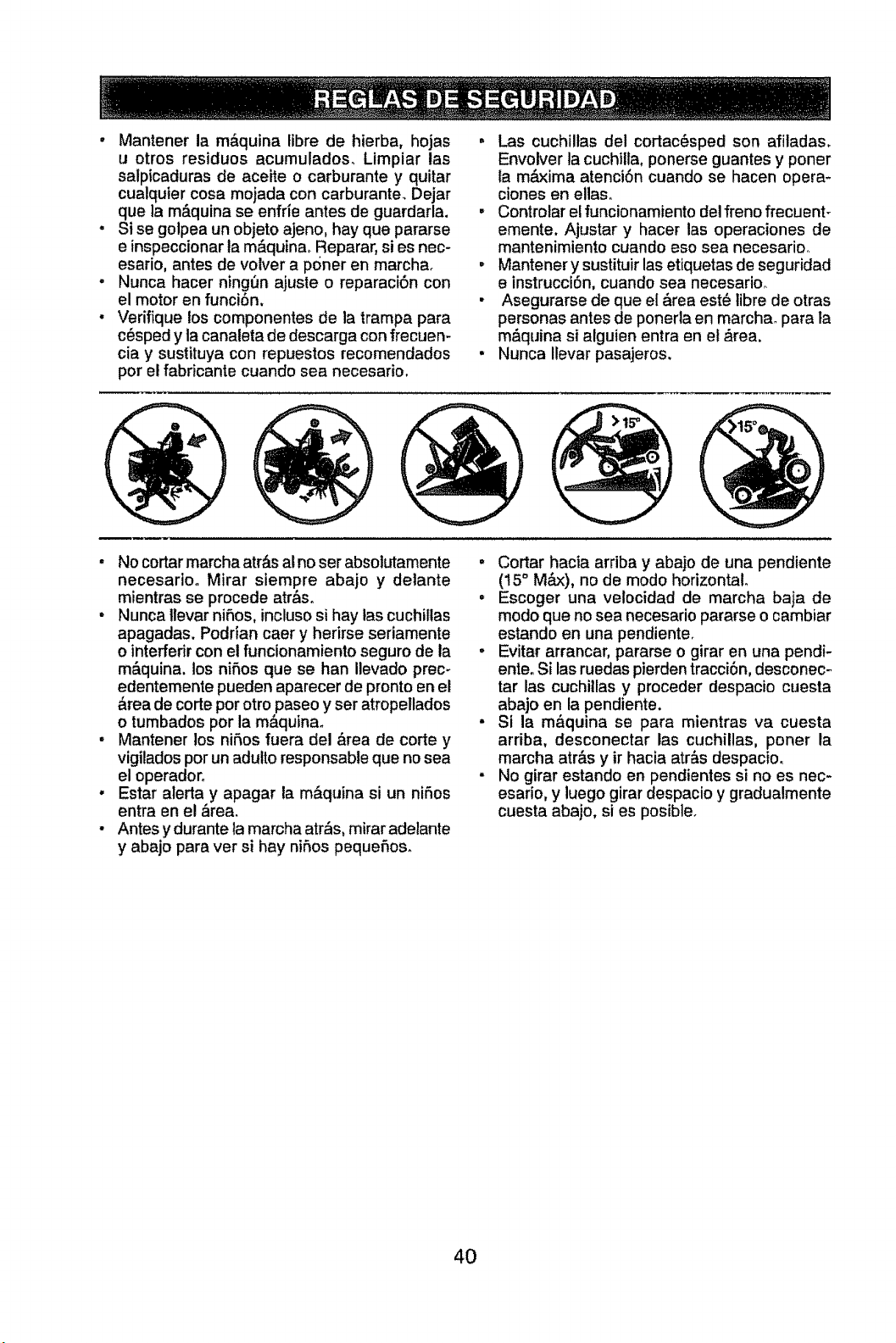
o Mantener la m&quina libre de hierba, hojas .
u otros residuos acumulados_ Limpiar las
salpicaduras de aceite o carburante y quitar
cualquier cosa mojada con carburante. Dejar
que la m&quina se enfrie antes de guardarla. .
Si se golpea un objeto ajeno, hay que pararse
e inspeccionar ta m&quina_ Reparar, si es nec-
esario, antes de volver a poner en marchao °
Nunca hacer ningt3n ajuste o reparaci6n con
el motor en funci6n.
Verifique los componentes de ta trampa para
c6sped y la canaleta de descarga con frecuen-
ciay sustituya con repuestos recomendados •
por el fabricante cuando sea necesarim
o
Las cuchillas del cortac6sped son afitadas.
Envolver la cuchitla, ponerse guantes y poner
ta m&xima atenci6n cuando se hacen opera-
clones en elias,.
Controlar el funcionamiento del freno frecuent-
emente. Ajustar y hacer las operaciones de
mantenimiento cuando eso SeEnecesarioo
Mantener y sustituir las etiquetas de seguridad
e instrucci6n, cuando sea necesarioo
Asegurarse de que el &rea est_ libre de otras
personas antes de ponerla en marcha, para la
m&quina si alguien entra en el ,_rea.
Nunca ilevar pasajeros.
• No cortar marcha atr,_sal no ser absolutamente
necesario. Mirar siempre abajo y delante
mientras se procede atr&s.
. Nunca llevar niSos, incluso si hay tas cuchillas
apagadas. Podrian caer y herirse seriamente
o interfedr con el funcionamiento seguro de la
m&quina, los nifios que se han Ilevado prec-
edentemente pueden aparecer de pronto en el
&tea de corte por otro paseo y ser atropellados
o tumbados por la m&quinao
° Mantener los niSos fuera del &rea de corte y
vigilados por un adutto responsable que no sea
el operador_
. Estar alerta y apagar la m&quina si un niAos
entra en el _rea,
• Antes y durante la marcha atr_s, mirar adelante
y abajo para ver si hay niSos pequefios.
. Cortar hacia arriba y abajo de una pendiente
(t5 ° M_x), no de modo horizontal
• Escoger una velocidad de marcha baja de
modo que no sea necesario pararse o cambiar
estando en una pendiente.
. Evitar arrancar, pararse o girar en una pendi-
enle. Si las ruedas pierden tracci6n, desconec-
tar las cuohillas y proceder despacio cuesta
abajo en la pendiente.
• Si la m&quina se para mientras va cuesta
arriba, desconectar las cuchillas, poner la
marcha atr&s y ir hacia atr&s despacio.
. No girar estando en pendientes si no es nec-
esario, y luego girar despacio y gradualmente
cuesta abajo, si es posible.
4O
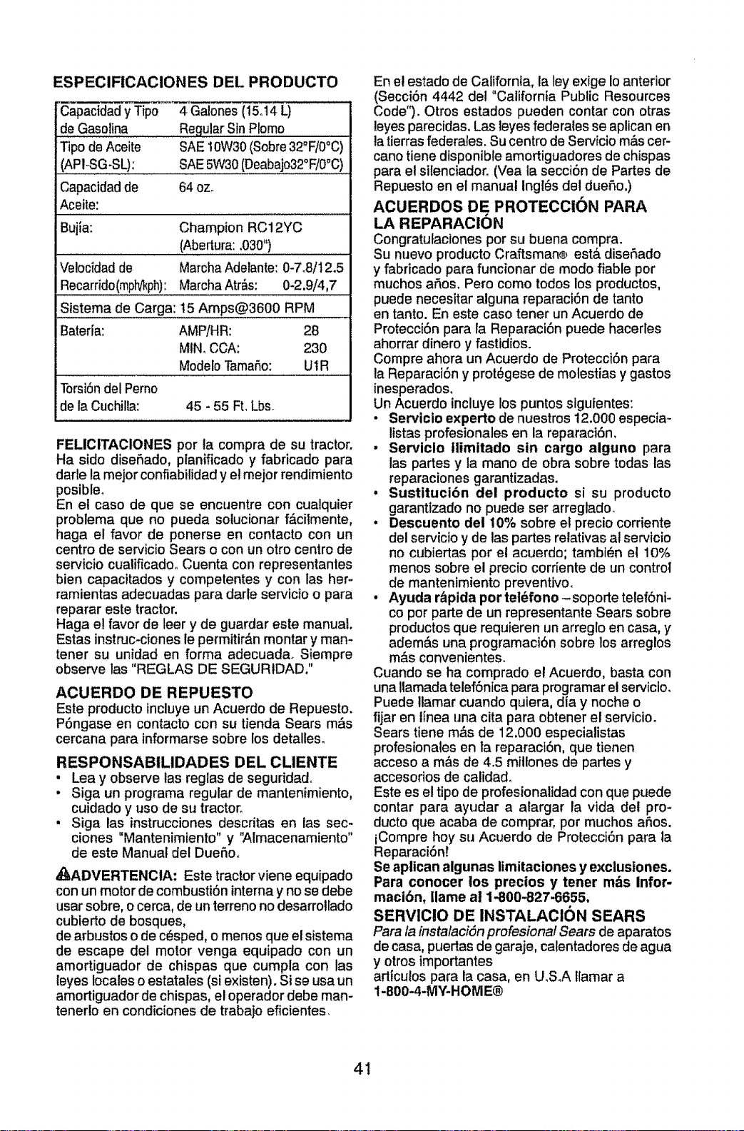
ESPECIFICACIONES DEL PRODUCTO
Capacidad y Tipo
de Gasolina
Tipo de Aceite
(AP1-SG-SL):
Capacidad de
Aceite:
4 Galones(15ol4 L)
Regular Sin Plomo
SAE10W30(Sobre32°F/0°C)
SAE5W30 (Deabajo32°F/0°C)
64 oz.
BujJa: Champion RC12YC
(Abertura:.030")
Velocidad de MarchaAdetante: 0-7.8/12.5
Recarrido(mph/!_ph):Marcha Atr_s: 0-2,9/4,7
Sistema de Carga: 15 Amps@3600 RPM
BaterJa: AMPiHR: 28
MIN.CCA: 230
Modelo TamaSo: UI R
Torsi6ndel Perno
de la Cuchilla: 45 - 55 Ft. Lbs.
FELICITACIONES por la compra de su tractor.
Ha sido diseBado, planificado y fabricado para
darle la mejor confiabilidad y et mejor rendimiento
posibleo
En el caso de que se encuentre con cualquier
problema que no pueda sotucionar f,_cilmente,
haga el favor de ponerse en contacto con un
centro de servicio Sears o con un otro centro de
servicio cualificado. Cuenta con representantes
bien capacitados y competentes y con las her-
ramientas adecuadas para darle servicio o para
reparar este tractor.
Haga el favor de leer y de guardar este manual.
Estas instruc-ciones le permitir&n montar y man-
tener su unidad en forma adecuada. Siempre
observe las "REGLAS DE SEGURtDAD."
ACUERDO DE REPUESTO
Este producto incluye un Acuerdo de Repuesto.
P6ngase en contacto con su tienda Sears m_s
cercana para informarse sobre los detalles.
RESPONSABILIDADES DEL CLIENTE
, Lea y observe las reglas de seguridado
, Siga un programa regular de mantenimiento,
cuidado y uso de su tractor.
• Siga las instrucciones descritas en las sec-
clones "Mantenimiento" y '_Imacenamiento"
de este Manual del DueSoo
_ADVERTENCIA: Este tractor viene equipado
con un motor de combusti6n internay no se debe
usar sobre, o cerca, de un terreno no desarrotlado
cubierto de bosques,
de arbustos o de c_sped, o menos que el sistema
de escape del motor venga equipado con un
amortiguador de chispas que cumpla con las
leyes locales o estatales (si existen). Si se usa un
amortiguador de chispas, el operador debe man-
tenerlo en condiciones de trabajo eficientes.
En e! estado de California, la ley exige Io anterior
(Secci6n 4442 del "California Public Resources
Code'°). Otros estados pueden contar con otras
leyes parecidas. Las leyes federales se aplican en
latierras federales. Su centro de Servicio m&s cer-
cano tiene disponible amortiguadores de chispas
para el silenciador_ (Vea la secci6n de Partes de
Repuesto en el manual ingles del due5o,)
ACUERDOS DE PROTECCION PARA
LA REPARACION
Congratutaciones por su buena comprao
Su nuevo producto Craftsman® est_ dise_,ado
y fabricado para funcionar de modo fiable por
muchos aSos. Pero como todos los productos,
puede necesitar alguna reparaci6n de tanto
en tanto. En este caso tenet un Acuerdo de
Protecci6n para la Reparaci6n puede hacerles
ahorrar dinero y fastidios.
Compre ahora un Acuerdo de Protecci6n para
la Reparaci6n y prot_gese de molestias y gastos
inesperados.
Un Acuerclo incluye los puntos siguientes:
• Ser,/icio experto de nuestros 12o000especia _
listas profesionales en la reparaci6n,
• Serviclo tlimitado sin cargo alguno para
las partes y la mano de obra sobre todas las
reparaciones garantizadas.
• Sustitucibn del producto si su producto
garantizado no puede set arreglado_
• Descuento del 10% sobre el precio corriente
del servicioy de las partes relativas at servicio
no cubiertas por el acuerdo; tambi_n e! 10%
menos sobre el precio corriente de un control
de mantenimiento preventivo.
• Ayuda r_pida por tel6fono-soporte telef6ni-
co por parte de un representante Sears sobre
productos que requieren un arreglo en casa, y
adem&s una programaci6n sobre los arreglos
m&s convenientes.
Cuando se ha comprado el Acuerdo, basta con
unallamada telef6nica para programar el servicio.
Puede Ilamar cuando quiera, dia y noche o
fijar en lJneauna cita para obtener el servicio.
Sears tiene rods de 12.000 especiatistas
profesionales en la reparaciSn, que tienen
acceso a m&s de 4.5 millones de partes y
accesorios de calidad.
Este es el tipo de profesionalidad con que puede
contar para ayudar a alargar la vida det pro-
ducto que acaba de comprar, por muchos aSos.
iCompre boy su Acuerdo de Protecci6n para la
Reparaci6nt
Se aplican algunas limitaciones y exclustones.
Para conocer los precios y tener m_s Infor-
macibn, Ilame al 1-800-827.6655,
SERVICIO DE INSTALACION SEARS
Para /a insta/aci&n profesiona/ Sears de aparatos
de casa, puertas de garaje, calentadores de agua
y otros importantes
articutospara la casa, en U,S_A flamar a
1-800-4-MY-HOME®
4t
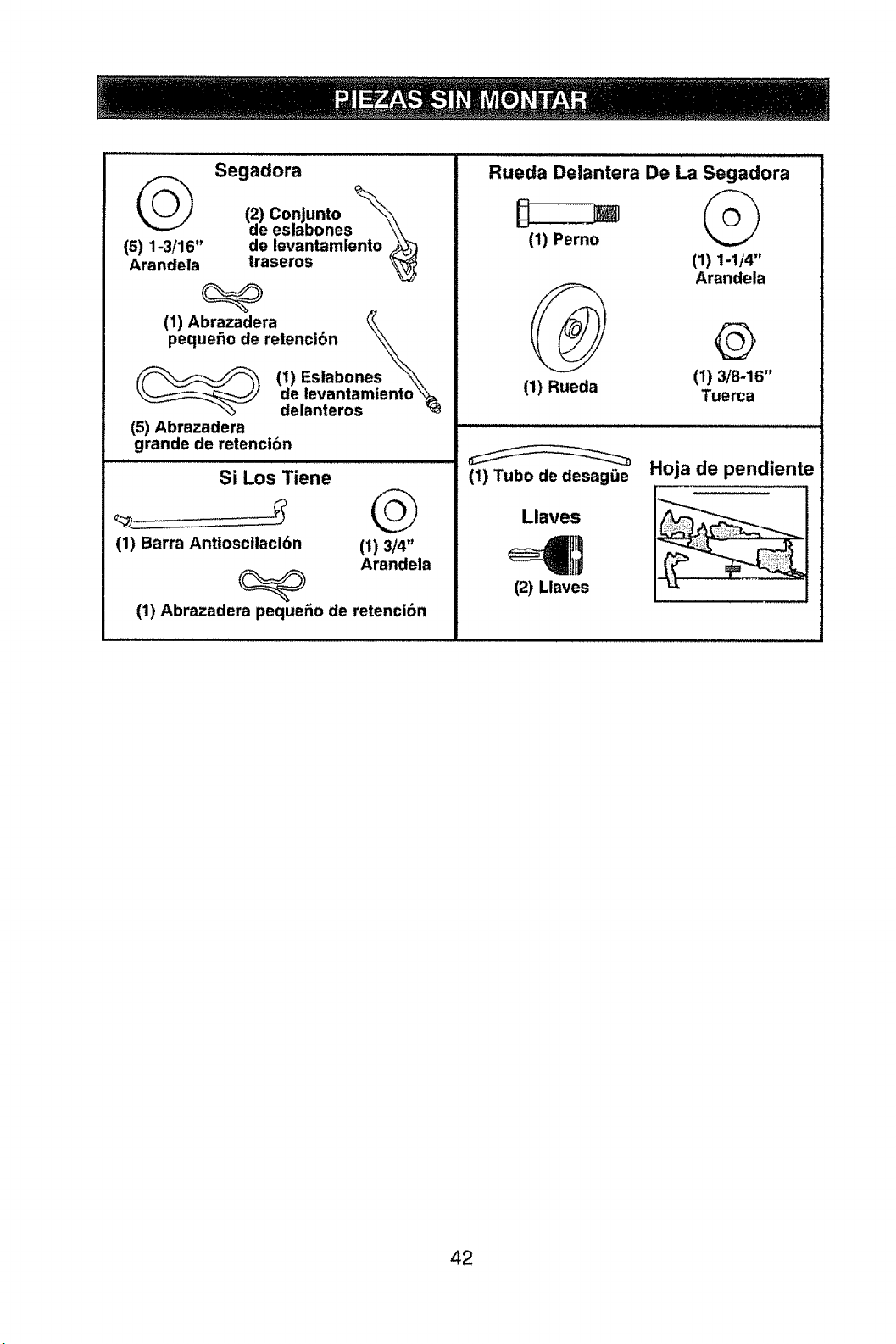
Segadora
(2) Conjunto
de eslabones
(5) 1-3/16" de levantamiento
Arandela traseros
(1) Abrazadera
pequefio de retenci6n \_\
(___ (1) Eslabones \_\
\______j' de levantamtento \_
"% delanteros
(5) Abrazadera
grande de retencibn
Si Los Tiene
(1) Barra Antioscllaci6n (1) 3/4"
Arandela
(1) Abrazadera peque_o de retencibn
Rueda Delantera De La Segadora
(1) Perno
(1)1.1/4"
Arandela
(1) 3/8-16"
Tuerca
(1) Rueda
(1) Tubo de desagQe
Llaves
(21 Llaves
Hoja de pendiente
42
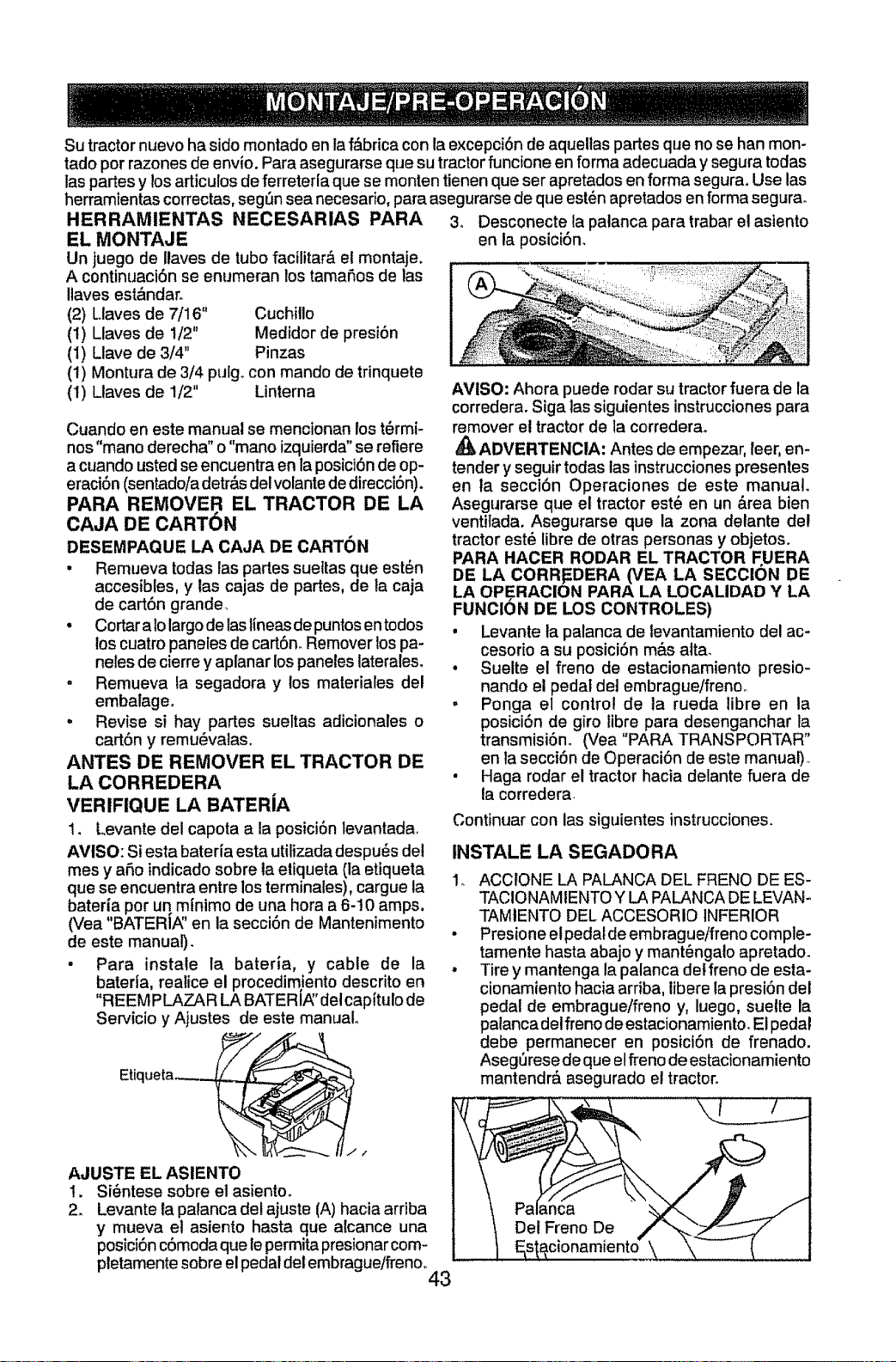
Su tractor nuevo ha sido montado en la f_brica con la excepci6n de aquellas partes que no se han mon-
tado por razones de envio. Para asegurarse que su tractor funcione en forma adecuada y segura todas
las partes y los articulos de ferreterla que se monten tienen que ser apretados en forma segura. Use las
herramientas correctas, segSn sea necesado, para asegurarse de que est_n apretados en forma segura_
HERRAMIENTAS NECESARIAS PARA
EL MONTAJE
Un juego de llaves de tubo facilitar& el montaje.
A continuaci6n se enumeran los tama5os de las
Ilaves est&ndaro
(2) Liaves de 7/16" Cuchillo
(1) Llaves de 1/2" Medidor de presi6n
(I) Llave de 3/4" Pinzas
(1) Montura de 3/4 pulgo con mando de trinquete
(I) Llaves de 1/2" Linterna
Cuando en este manual se mencionan los t_rmi-
nos "mano derecha" o "mano izquierda"se refiere
a cuando usted se encuentra en la posici6n de op-
eraci6n (sentado/a detr_,sde! volante de direcci6n).
PARA REMOVER EL TRACTOR DE LA
CAJA DE CART6N
DESEMPAQUE LA CAJA DE CARTON
• Remueva todas las partes sueltas que est_n
accesibles, y las cajas de partes, de ta caja
de cart6n grande_
• Cortar a 1olargode laslineasde puntosen todos
los cuatro paneles de cart6noRemover ios pa-
neles de cierre y aplanar lospaneles laterales.
, Remueva ta segadora y los materiales del
embalage.
, Revise si hay partes sueltas adicionales o
cart6n y remu_valas.
ANTES DE REMOVER EL TRACTOR DE
LA CORREDERA
VERIFIQUE LA BATERiA
1. Levante del capota a la posici6n levantada.
AMISO: Siesta bateria esta utilizada despu_s del
mes y aSo indicado sobre ta etiqueta (la etiqueta
que se encuentra entre los terminales), cargue la
bateria por un minimo de una hora a 6-10 amps.
(Vea "BATERI/_' en la secci6n de Mantenimento
de este manual).
, Para instale la bateria, y cable de la
bateria, realice el procedimiento descrito en
"REEM PLAZAR LA BATERi_' delcapitulo de
Servicio y Ajustes de este manual.
Etiqueta _
AJUSTF EL ASIENTO
1. Si_ntese sobre et asientoo
2. Levante la palanca de! ajuste (A) hacia arriba
y mueva et asiento hasta que alcance una
posici6n c6moda que le permitapresionar com-
pletamente sobre el pedal del embrague/freno_
43
3o Desconecte la palanca para trabar el asiento
en ia posici6no
AViSO: Ahora puede rodar su tractor fuera de la
corredera. Siga ias siguientes instruccionespara
remover e! tractor de la corredera_
ADVERTENCIA: Antes de empezar, leer, en-
tender y seguir todas las instruccionespresentes
en la secci6n Operaciones de este manual.
Asegurarse que el tractor est6 en un &rea bien
ventitada. Asegurarse que la zona delante det
tractor est_ libre de otras personas y objetos.
PARA HACER RODAR EL TRACTOR F,UERA
DE LA CORR_DERA (VEA LA SECCION DE
LA OPERACION PARA LA LOCALIDAD Y LA
FUNCION DE LOS CONTROLES)
, Levante la palanca de levantamiento del ac-
cesorio a su posici6n m&s alta.
* Suelte el freno de estacionamiento presio-
nando el pedal de] embrague/frenoo
, Ponga el control de ]a rueda tibre en la
posici6n de giro libre para desenganchar la
transmisi6no (Vea "PARA TRANSPORTAR"
en la secci6n de Operaci6n de este manual)_
, Haga rodar el tractor hacia delante fuera de
la corredera.
Continuar con las siguientes instrucciones.
INSTALE LA SEGADORA
.
s
ACCfONE LA PALANCA DEL FRENO DE ES-
TACIONAMIENTO Y LA PALANCA DE LEVAN-
TAMIENTO DEL ACCESORIO INFERIOR
Presione el pedal de embrague/freno comple-
tamente hasta abajo y mant_ngato apretado.
Tire y mantenga la palanca det freno de esta-
cionamiento hacia ardba, tibere la presi6n det
pedal de embrague/freno y, luego, suelte la
palanca del freno de estacionamiento. EI pedal
debe permanecer en posici6n de frenado.
Aseg_rese de que el freno de estacionamiento
mantendr& asegurado el tractor.
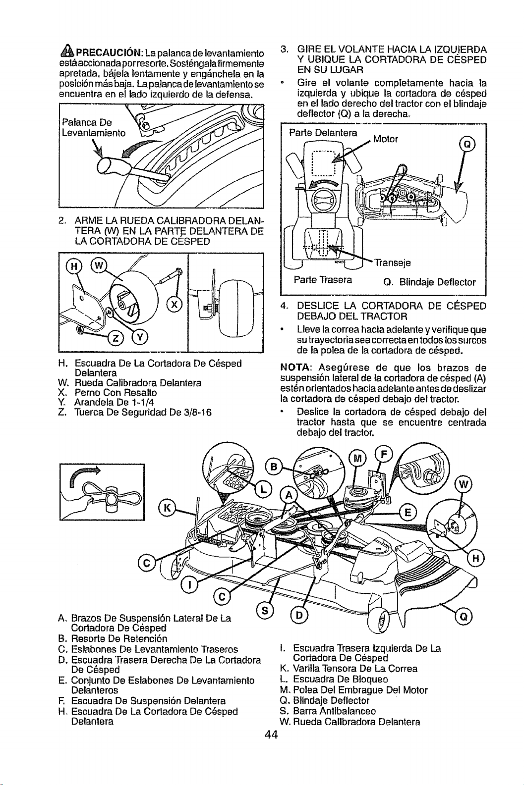
PRECAUCION: La palanca de levantamiento
est&accionada por resorte. Sost_ngalafirmemente
apretada, b&jela lentamente y eng&nchela en la
posiciSnm&s baja. La palanca de levantamiento se
encuentra en el lado izquierdo de la defensa.
Palanca De
Levantamiento
2. ARME LA RUEDA CALIBRADORA DELAN-
TERA (W) EN LA PART.E DELANTERA DE
LA CORTADORA DE CESPED
H. Escuadra De La Cortadora De C_sped
Delantera
W. Rueda Calibradora Detantera
X. Perno Con Resalto
"Y'_Arandela De t-1/4
Z. 3iJerca De Seguridad De 3/8-16
3. GIRE EL VOLANTE HACtA LA IZQUfERDA
Y UBIQUE LA CORTADORA DE CESPED
EN SU LUGAR
, Gire el volante completamente hacia la
izquierda y ubique la cortadora de c_sped
en el lado derecho del tractor con el blindaje
deflector (Q) a la derecha.
Parte Delantera
Motor
Pane Trasera Q. Blindaje Deflector
4o DESLICE LA CORTADORA DE CESPED
DEBAJO DEL TRACTOR
• Lleve la correa hacia adelante y verifique que
su trayectoria seacorrecta en todos los surcos
de la polea de la cortadora de c_sped.
NOTA: Aseg_trese de que los brazos de
suspensi6n lateral de la cortadora de c_sped (A)
est_n orientados hacia adelante antes de deslizar
la cortadora de c_sped debajo del tractor_
• Deslice la cortadora de c_sped debajo del
tractor hasta que se encuentre centrada
debajo del tractor.
A. Brazos De Suspensi6n Lateral De La
Cortadora De C_sped
Bo Resorte De Retenci6n
Co Eslabones De Levantamiento Traseros
D. Escuadra Trasera Derecha De La Cortadora
De C_ped
E. Conjunto De Eslabones De Levantamiento
Delanteros
E Escuadra De SuspensiSn Detantera
H. Escuadra De La Cortadora De C_sped
Delantera
I. Escuadra Trasera tzquierda De La
Cortadora De C_sped
Ko Varilla Tensora De La Correa
L. Escuadra De Btoqueo
M. Polea Del Embrague De! Motor
Q. Blindaje Deflector
S. Barra Antibalanceo
Wo Rueda Callbradora Delantera
44
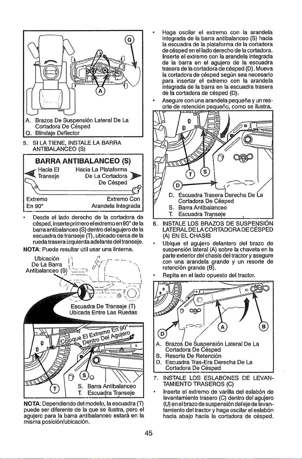
A. Brazos De Suspensi6n Lateral De l.a
Cortadora De C_sped
Q. Blindaje Deflector
5. SI LA TIENE, INSTALE LA BARRA
ANTIBALANCEO (S)
BARRA ANTIBALANCEO (S)
_ Hacia El Hacia La Plataforma
Transeje De La Cortadora ,_l_
_k_ De C_sped
iiiiiiiiiiiii..............
Extremo Extremo Con
En 90° Arandeta lntegrada
• Desde e! lado derecho de la cortadora de
c_sped, inserte primero et extremo en 90" de la
barra antibalanceo (S) dentro del agujero de la
escuadra de transeje (T), ubicado cerca de la
rueda trasera izquierda adelante deltransejeo
NOTA: Puede resultar t]til usar una linterna.
Ubicaci6n i_ .'_ .-
De La Barra 't I _'_ ; ............ "_
Antibalanceo (S) L_._'_ I \
Escuadra De Transeje (T)
Ubicada Entre Las Ruedas
Escuadra Transeje
NOTA: Dependiendo det modelo, ta escuadra (T)
puede ser diferente de la que se ilustra, pero el
agujero para la barra antibalanceo estar& en la
misma posici6niubicaci6n_
45
. Haga oscilar el extremo con la arandela
integrada de ta barra antibalanceo (S) hacia
la escuadra de la plataforma de la cortadora
de c_sped en e[ lado derecho de la cortadorao
Inserte el extremo con la arandela integrada
de la barra en el agujero de la escuadra
trasera de la cortadora de c6sped (D). Mueva
fa cortadora de c6sped segt_n sea necesario
para insertar el extremo con la arandela
integrada de la barra en la escuadra trasera
de la cortadora de c6sped (D).
. Asegure con una arandela pequefia y un res-
orte de retenci6n pequefio, como se ilustra.
T. Escuadra
6. INSTALE LOS BRAZOS DE SUSPENSION
LATERAL DE LA CO RTADORA DE CESPED
(A) EN EL CHASIS
• Ubique et agujero delantero det brazo de
suspensi6n lateral (A) sobre la chaveta en la
parle exterior del chasis det tractor y asegure
con una arandela grande y un resorte de
retenci6n grande (B).
• Repita en el lado opuesto del tractor.
B. Resorte De Retenci6n
D. Escuadra Tras-Era Derecha De La
Cortadora De C6sped
7, INSTALE LOS ESLABONES DE LEVAN-
TAMIENTO TRASEROS (C)
Inserte el extremo de varilla det eslab6n de
levantamiento trasero (C) dentro del agujero
(U) en el brazo de suspensi6n del eje de tevan-
tamiento det tractor y haga oscilar el eslab6n
hacla abajo hacia la cortadora de c_spedo
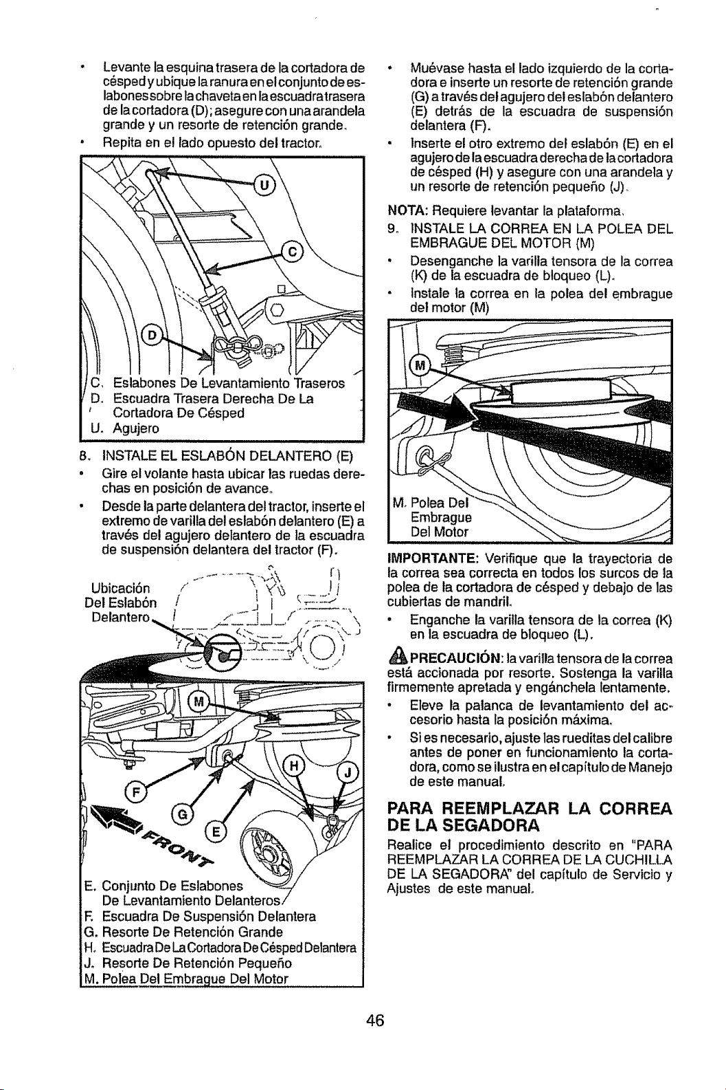
• Levantelaesquinatraseradelacortadorade
c_spedyubiquelaranuraenetconjuntodees-
labonessobrelachavetaenlaescuadratrasera
delacortadora(D);asegureconunaarandela
grandeyunresortederetenci6ngrande.
• Repitaenel ladoopuestodeitractor°
C_
Eslabones De Levantamiento Traseros
Escuadra Trasera Derecha De La
Cortadora De C_sped
U. Agujero
8_
o
Ubicaci6n
Del Eslab6n
INSTALE EL ESLAB6N DELANTERO (E)
Gire el volante hasta ubicar las ruedas dere-
chas en posici6n de avanceo
Desde la parle delantera del tractor, insede el
extremo de varilla del estab6n delantero (E) a
trav_s dei agujero delantero de la escuadra
de suspensi6n delantera del tractor (F).
................. rt
i' I_ ;=.:::_l
]
De Levantamiento D_
E Escuadra De Suspensi6n Delantera
G. Resorte De Retenci6n Grande
H. Escuadra DeLaCortadoraDeC_spedDelantera
Jr Resorte De Retenci6n Peque5o
M, Polea Del E mbrague Del Motor ......
• Mu6vase hasta el lado izquierdo de la coma-
dora e insede un resorte de retenci6n grande
(G) a trav_s del agujero del eslab6n delantero
(E) detr,_s de la escuadra de suspensi6n
delantera (F).
• lnsede el otro extremo det eslab6n (E) en el
agujero de la escuadra derecha de la cortadora
de c_sped (H) y asegure con una arandeta y
un resode de retenciOn peque5o (J).
NOTA: Requiere levantar la plataforma.
9. INSTALE LA CORREA EN LA POLEA DEL
EMBRAGUE DEL MOTOR {M)
o Desenganche la varilla tensora de la correa
(K) de la escuadra de b!oqueo (L).
° Instale la correa en la polea del embrague
del motor (M)
M. Polea Del
Embrague
Del Motor
IMPORTANTE: Veriflque que la trayectoria de
la correa sea correcta en todos los surcos de la
polea de ta cortadora de c_sped y debajo de las
cubierlas de mandril.
, Enganche la varilla tensora de ta correa (K)
en ta escuadra de bloqueo (L).
PRECAUTION: la variIla tensora de lacorrea
est& accionada por resorte. Sostenga la varilla
firmemente apretada y eng&nchela lentamente.
• Eleve la palanca de levantamiento del ac-
cesorio hasta la posici6n m&xima_
• SI es necesario, ajuste las rueditas delcalibre
antes de poner en funcionamiento la coma-
dora, como se ilustra en el capftulo de Manejo
de este manual.
PARA REEMPLAZAR LA CORREA
DE LA SEGADORA
Realice el procedimiento descrito en "PARA
REEMPLAZAR LA CORREA DE LA CUCHILLA
DE LA SEGADORA" del capftulo de Servicio y
Ajustes de este manual.
46
REVISION DE LA PRESI6N DE LAS
LLANTAS
Las llantas en su unidad fueron inftadas de-
masiado en la f&brica per razones de envioo La
presi6n de las llantas correctas es importante
para obtener el mejor rendimiento en el code.
Reduzca ia presi6n de los neum&ticos a la PS!
que se indica en estos,
REVISION DE LA NIVELACION DEL
CON JUNTO
Para obtener los rnejores resuttados en el corte,
la caja de la segadora tiene que estar nivelada
en la forma adecuada. Vea "PARA NIVELAR
LA CAJA DE LA SEGADORA" en la secci6n de
Servicio y Ajustes de este manual.
REVISION DE LA POSICION ADECUADA
DE TODAS LAS CORREAS
Vea las figuras que aparecen para cambiar las
correas de impulsi6n de la cuchilla de la sega-
dora y de movimiento en la secci6n de Servicio y
Ajustes de este manual. Vefifique que las correas
sigan su paso correcto.
REVISI6N DEL SISTEMA DE FRENOS
Una vez que usted haya aprendido a manejar su
tractor, verifique que et freno funcione correcta-
mente. Ver "PARA VERIFICAR SI FUNCIONA
BIEN EL FRENO" en el capitulo de servicio y
ajustes de este manual
_'LISTA DE REVISION
Antes de operary de disfrutarde su tractor nuevo,
le deseamos que reciba el mejor rendimientoy fa
mayor satisfaccion de este productode catidad.
Haga el favor de revisar fa lista a continuacion:
t,# Se han completado todas las instruccionesde
montaje.
J" No quedan partessueltas en la caja de cart6n.
t/f La bateria est& preparada y cargada en forma
adecuadao
J El asiento ha sido ajustado en forma c6moda
y apretado en forma segura.
ef Todas las Ilantas han sido infladas en forma
adecuadao (Para fines de envio, las llantas se
inflaron demasiado en la fbbricao)
vf AsegSrese que el conjunto segador est_
nivelado en forma adecuada, de lado a lado
y desde adelante hacia atr&s, para obtener los
mejores resultados en el corte. (Las Ilantas
tienen que estar infladas en forma adecuada
para la nivelaci6n.)
vf Revise las correas de impulsi6n y de la
segadora. Aseg6rese que recorran el paso
adecuado alrededor de las poleas y dentro
de todos los fijadores de las correaso
v# Revise el alambrado. Fijese que todas las
conexiones todavfa esten segurasy que los
alambres est6n sujetos en forma adecuadao
v( Antes de conducir el tractor, aseg6rese que
el control de rueda tibre este en la posici6n
de "transmisi6n enganchada" (Vea "PARA
TRANSPORTAR" en la secci6n de la Oper_
aci6n de este manual).
AI mismo tiempo que aprende a como usar su
tractor, preste atencion extra a los puntos de
importancia que se presentan a continuacion:
vf El aceite del motor tiene que Ilegar at nivel
adecuado.
_" Elestanque de combustible tiene que estar Ileno
con gasolina sin plomo regular, nueva y limpia.
vf Familiaricese con todos los controtes - su
ubicaci6n y su funci6m Op6relos antes de
hacer arrancar el motor.
_/" Asegurese que el sistema de frenos est_ en
una condici6n de operacion segura.
vf Asegurarse de que el Sistema de Presencia
del Operador y el Sistema de Funcionamiento
Atr_s (ROS) funcionan de modo adecuado
(Ver las Secciones de Funcionamiento y
Mantenimiento en este manual)_
Es importante purgar la transmisi6n antes
de operar su tractor por la primera vez. Siga
las tnstruccionesadecuadas para el empiezo
y para purgar (Vea "PARA EMPESAR EL
MOTOR" y "PARA PURGAR LA TRANS-.
MISION" en la secci6n de ta Operaci6n de
este manual
47
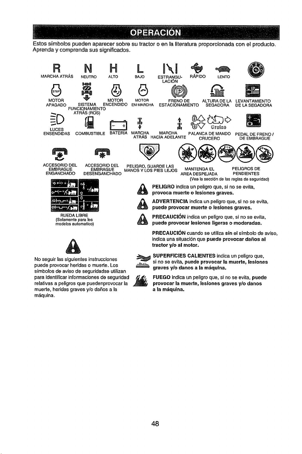
Estos sfmbolos pueden aparecer sobre su tractor o en ;a literatura proporcionada con el producto_
Aprenda y comprenda sus significados.
Fl N H L
MARCHA ATRAS NEUTRO ALTO BAJO
MOTOR
APAGADO
LUCKS
ENSENDIDAS
" G
" ¢)
MOTOR MOTOR
SISTEMA ENCENDIDO EN MARCHA
FUNCIONAMIENTO
ATRAS (ROS)
COMBUSTIBLE
ACCESOR;O DEL
EMBRAGUE
ENGANCHADO
ESTRA_GU- RAPfDO LENTO
LACION
(@)
FRENO DE ALTUBA DE LA
ESTAC;ONAMIENTO SEGADORA
LEVANTAMtENTO
DE LA SEGADORA
BATERJA MAFICHA MARCHA PALANCA DE MANDO PEDAL DE FRENOt
ATRAS HAOIA ADELANqrE CRUCERO DE EMBRAGUE
l
ACCESORIO DEL
EMBRAGUE
DESENGANCHADO
RUEDA LIE}RE
(Solamente para los
modelos aulomatico)
PELIGRO, GUARDE LAS
MANOS Y LOS PIES LEJOE; MANTENGA EL PEL|GROS DE
AREA DESPEJADA PENDIENTES
(Vaa la secci6n de ;as teglas de seguridad)
PELIGRO indica un peligro que, si no se evita,
provoca muerte o leslones graves.
ADVERTENC1A {rid{caun peligro que, st no se evtta,
puede provocar muerte o leslones graves.
PRECAUCION indica un peligro que, si no se evita,
puede provocar lesiones ligeras o moderadas.
PRECAUCION cuando se utiliza sin el simbolo de aviso,
indica una situaci6n que puede provocar dafios al
tractor y/o al motor,
No seguir las siguientes instrucciones
puede provocar heridas o muerte. Los
simbolDs de aviso de seguridadse ulilizan
para |dentil|car informaciones de seguridad
relattvas a peligros que puedenprovocar ta
muerte, heridas graves y/o dafios a la
mdquina.
SUPERFICIES CALIENTES indica un peligro que,
si no se evtta, puede provocar la muerte, lesiones
graves y/o danos a la m_qutna,
FUEGO indica un peligro que, sl no se evila, puede
provocar la muerte, lesiones graves y/o danos
a la mfiqutna.
48
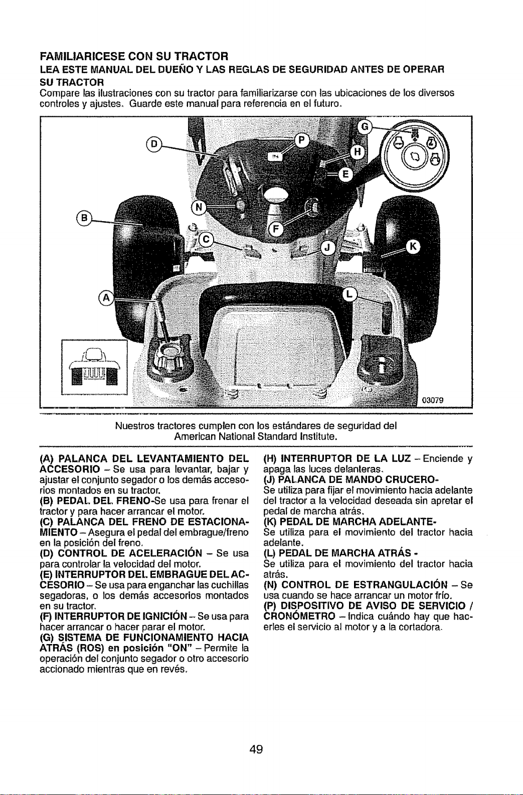
FAMILIARICESE CON SU TRACTOR
LEA ESTE MANUAL DEL DUEI_IO Y LAS REGLAS DE SEGURIDAD ANTES DE OPERAR
SU TRACTOR
Compare las ilustraciones con su tractor para familiarizarse con tas ubicaciones de los diversos
controles y ajustes. Guarde este manual para referencia en el futuroo
03079
Nuestros tractores cumplen con los estdndares de seguridad del
American National Standard Institute.
(A) PALANCA DEL LEVANTAMIENTO DEL
ACCESORIO -Se usa para levantar, bajar y
ajustar el conjunto segador o los dem&s acceso-
rids montados en su tractor.
(B) PEDAl.. DEL FRENO-Se usa para frenar el
tractor y para hacer arrancar el motor.
(C) PALANCA DEL FRENO DE ESTACIONA-
MIENTO - Asegura et peda! del embrague/freno
en ta posici6n det freno.
(D) CONTROL DE ACELERACION - Se usa
para controlar la velocidad del motor.
(E) INTERRUPTOR DEL EMBRAGUE DEL AC-
CESORIO - Se usa para enganchar las cuchillas
segadoras, o los dem&s accesorios montades
en su tractor.
(F) INTERRUPTOR DE IGNICION - Se usa para
hacer arrancar o hacer parar el motor.
(G) S ISTEMA DE FUNCIONAMIENTO HACIA
ATRAS (ROS) en posici6n "ON" -Permite ta
operad6n de! conjunto segador o otro accesodo
accionado mientras queen rev_s.
(H) INTERRUPTOR DE LA LUZ -Enciende y
apaga las luces detanteras°
(J) PALANCA DE MANDO CRUCERO*
Se utiliza para fijar el movimiento hacia adelante
del tractor a la velocidad deseada sin apretar e!
pedal de marcha atr&s.
(K) PEDAL DE MARCHA ADELANTE-
Se utiliza para el movimiento del tractor hacia
adelante.
(L) PEDAL DE MARCHA ATRAS ..
Se utiliza para e! movimiento del tractor hacia
atr_s.
(N) CONTROL DE ESTRANGULACl6N -Se
usa cuando se hace arrancar un motor frio.
(P) DISPOSrTIvo DE AVlSO DE SERVIClO /
CRONOMETRO -Indica cu&ndo hay que hac-
edes et ser¢icio al motor y a ta cortadora.
49
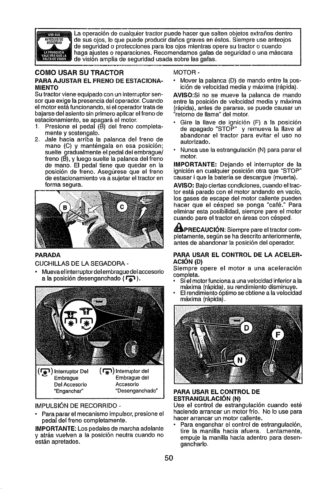
La operaciSn de cualquier tractor puede hacer que salten objetos extraSos dentro
de sus ojos, Io que puede producir daSos graves en _stos, Siempre use anteojos
de seguridad o protecciones para los ojos mientras opere su tractor o cuando
haga ajustes o reparaciones. Recomendamos gafas de seguridad o una m_scara
de visiSn amplia de seguridad usada sobre las gafaso
COiVtO USAR SU TRACTOR
PARA AJUSTAR EL FRENO DE ES'TACIONA-
MIENTO
Su tractor viene equipado con un interruptor sen-
sor que exige ta presencLadel operador. Cuando
el motor est&funcionando, si el operador trata de
bajarse del asiento sin primero aplicar el freno de
estacionamiento, se apagar& el motor_
I_ Presione et pedal (B) de! freno completa-
mente y sostengalo,
2o Jale hacia arriba la palanca del freno de
mano (C) y mant_ngata en esa posiciSn;
suelte gradualmente el pedal del embrague/
freno (B), y luego suelte ta palanca del freno
de manoo El pedal tiene que quedar en la
posici6n de freno, Aseg_rese que el freno
de estacionamiento va a sujetar et tractor en
forma segurao
MOTOR -
• Mover la palanca (D) de mando entre la pos-
ici6n de ve!ocidad media y m_xima (r&pida)o
AVISO:Si no se mueve la palanca de mando
entre la posici6n de velocidad media y m&xima
(r&pida), antes de pararse, se puede causar un
"retorno de llama" del motor,
• Gire la Itave de ignici6n (F) a fa posici6n
de apagado "STOP" y remueva la Ilave al
abandonar et tractor para evitar el uso no
autorizado.
, Nunca use ta estrangulaciSn (N) para parar el
motor,
IMPORTANTE: Dejando el interruptor de la
ignici6n en cualquier posiciSn otra que "STOP"
causar i que la bater[a se descargue (muerta),
AVISO: Bajo ciertas condiciones, cuando et trac-
tor est& parado con el motor andando en vacio,
los gases de escape del motor caliente pueden
hacer que el c_sped se ponga "caf6." Para
eliminar esta posibilidad, siempre pare el motor
cuando pare e! tractor en &reas con c_sped_
A_PRECAUCI6N: Siempre pare el tractor com-
pletamente, seg(m se ha descrito anteriormente,
antes de abandonar la posici6n det operador.
PARADA
CUCHILLAS DE LA SEGADORA -
• Mueva elinterruptor delembrague det accesorio
a la posici6n desenganchado ( _ ).
(_) Interruptor Del
Embrague
Del Accesorio
"Enganchar"
tnterruptordei
Embraguedel
Accesodo
"Desenganchado"
IMPULSION DE RECORRIDO
• Para parar el mecanismo lmpulsor, presione el
pedal del freno completamente.
IMPORTANTE: Los pedales de marcha adelante
y atr&s vuelven a la posiciSn neutra cuando no
est&n apretados.
PARA USAR EL CONTROL DE LA ACELER-
ACION (D)
Siempre opere el motor a una aceleraci6n
completa.
, Si el motor funciona a unavelocidad inferiora fa
m&xima (r&pida), su rendimiento disminuye.
• El rendimiento6ptimo se obtienea la velocidad
m&xima (r&pida).
PARA USAR EL CONTROL DE
ESTRANGULACI6N (N)
Use el control de estrangulaci6n cuando est_
haciendo arrancar un motor frio. No Io use para
hacer arrancar un motor caliente.
. Para enganchar el control de estrangulaci6n,
tire ia manilla hacia afuera, Lentamente,
empuje ta manilla hacia adentro para desen-
gancharlo,
5O
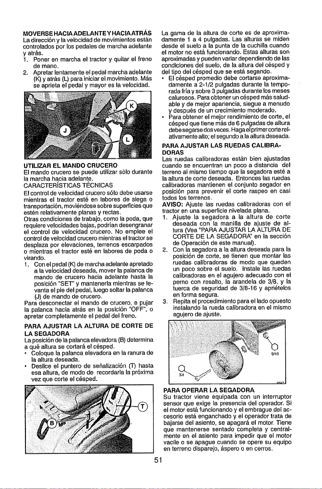
MOVERSE HACIA ADELANTE Y HACIA ATRAS
La direcci6n y la velocidad de movimientos est&n
controlados por los pedales de marcha adetante
y atr&s.
1. Poner en marcha el tractor y quitar el freno
de mano.
2_ Apretar lentamente el pedal marcha adelante
(K) y atr&s (L) para iniciaret movimiento. M&s
se aprieta el pedal y mayor es la velocidad.
UTILIZAR EL MANDO CRUCERO
El mando crucero se puede utilizar s6to durante
la marcha hacia adelante.
CARACTERISTICAS TI_CNICAS
El control de velocidad crucero s61odebe usarse
mientras et tractor est6 en labores de siega o
transportaci6n, movi_ndose sobre superficies que
est_n relativamente planas y rectas_
Otras condiciones de trabajo, como la poda, que
requiere velocidades bajas, podrJan desengranar
el control de velocidad crucero, No emplee el
control de ve!ocidad crucero mientras el tractorse
desplaza por elevaciones, terrenos escarpados
o mientras el tractor est_ en labores de poda o
virando.
!. Con el pedal (K) de marcha adelante apretado
a la velocidad deseada, mover la palanca de
mando de crucero hacia adelante hasta la
posiciSn "SET" y mantenerla mientras se le-
vanta el pie del pedal, luego sottar la palanca
(J) de mando de crucero.
Para desconectar e! mando de crucero, e pujar
ta palanca hacia atr&s en la posici6n "OFF", o
apretar completamente el pedal del freno.
PARA AJUSTAR LA ALTURA DE CORTE DE
LA SEGADORA
La posici6n de la palanca elevadora (B) determina
a qu_ altura se cortar& el c6sped.
• Coloque la palanca elevadora en ta ranura de
la altura deseada.
• Deslice el puntero de se5alizaci6n (T) hasta
esa altura, de modo de recordarla la pr6xima
vez que corte el c_sped.
51
La gama de la attura de corte es de aproxima-
damente t a 4 pulgadaso Las alturas se miden
desde et sueto a la punta de la cuchilla cuando
el motor no est,, funcionando_ Estas alturas son
aproximadas y pueden variar dependiendo de las
condiciones del suelo, de la altura det c_sped y
del tipo del c_sped que se est& segando.
. El c_sped promedio debe cortarse aproxima-
damente a 2-I/2 pulgadas durante la tempo-
rada fria y sobre 3 pulgadas durante los meses
calurososo Para obtener un c_sped m&s salud-
able y de mejor apariencia, siegue a menudo
y despu6s de un crecimiento moderado.
• Para obtener el mejor rendimiento de corte, el
c6sped que tiene m&s de 6 pulgadas de altura
debe segarse dos veces. Haga et primer cofle rel-
at_vamentealto; el segundo a laaltura deseadao
PARA AJUSTAR LAS RUEDAS CALIBRA-
DORAS
Las ruedas calibradoras est_n bien ajustadas
cuando se encuentran un poco a distancia del
terreno al mismo tiempo que la segadora est_ a
la attura de corte deseada. Entonces las ruedas
calibradoras mantienen et conjunto segador en
posici6n para prevenir el corte raspeo en casi
todos los terrenos.
AMISO; Ajuste las ruedas calibradoras con el
tractor en una superficie nivelada pfana.
1. Ajuste la segadora a ta altura de corte
deseada con la manilla de ajuste de al-
tura (Vea "PARA AJUSTAR LA ALTURA DE
CORTE DE LA SEGADOR,_' en la secci6n
de Operaci6n de este manual).
2. Con la segadora a la aftura deseada para fa
posici6n de corte, se tienen que montar las
ruedas calibradoras de mode que queden
un poco sobre el sueloo instale las ruedas
caltbradoras en el agujero adecuado con el
perno con resalto, la arandela de 3/8, y la
tuerca de seguridad de 3/8-16 y apri_telos
en forma segurao
3.. Repita el procedimiento para el lado opuesto
instalando la rueda calibradora en e! mismo
agujero de ajuste.
PARA OPERAR LA SEGADORA
Su tractor viene equipada con un interruptor
sensor que exige la presencia del operador. Si
et motor est& funcionando y el embrague del ac-
cesorio est& enganchado y el operador trata de
bajarse del asiento, se apagar& et motor. Tiene
que mantenerse sentado completa y central-
mente en el asiento para impedir que el motor
vacile o se apague cuando se opere su equipo
en terreno disparejo, _.spero o en cerros.
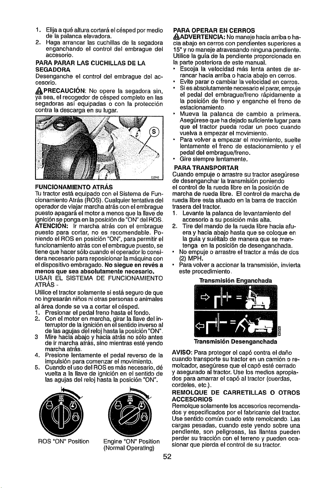
1. Etijaaqu6alturacortar&elc_spedpermealie
delapatancaelevadora.
2. Hagaarrancarlascuchillasde la segadora
enganchandoel controldel embraguedet
accesorio.
PARA PARAR LAS CUCHILLAS DE LA
SEGADORA
Desenganche el control del embrague del ac-
cesorio,
_PRECAUCtON: No opere la segadora sin,
ya sea, el recogedor de c_sped complete en las
segadoras asi equipadas o con la protecciOn
contra la descarga en su lugar.
FUNCIONAMtENTO ATRAS
Tu tractor est,. equipado con el Sistema de Fun-
cionamiento Atr&s (ROS). Cuatquier tentativa del
operador de viajar marcha atr&s con el embrague
puesto apagar& el motor a menos que la Ilave de
igniciOn se ponga en la posiciOn de "ON" del ROS.
A'rENCION: Ir marcha atr&s con el embrague
puesto para cortar, no es recomendable. Po-
niendo el ROS en posiciOn "ON", para permitir el
funcionamiento atr&s con el embrague puesto, se
tiene que hacer s61ocuando el operador Io consi-
dera necesario para reposicionar la m&quina con
el dispositivo embragado. No siegue en rev_s a
menos que sea absolutamente necesarlo,
USAR EL SISTEMA DE FUNCtONAMtENTO
ATRAS -
Utilice el tractor solamente si est& seguro de que
no ingresar&n nifios ni otras personas o animales
al &rea donde se va a cortar el c_sped,
1. Presionar el pedal freno hasta el fondo.
2. Con el motor en marcha, girar la Ilave del in-
terrupter de la igniciOn en el sentido inverse al
de ias agujas del reloj hasta la posiciOn "ON".
3 Mire hacia abajo y hacia atr&s no s01o antes
de ir marcha atr&s, sine mientras est_ yendo
marcha atr&s.
4. Presione lentamente el pedal reverse de la
impulsion para comenzar el movimiento.
5. Cuando el use del ROSes m&s necesario, d6
vuelta a la ltave de lgniciOn en el sentido de
las agujas del reloj hasta la posiciOn "ON".
ROB "ON" Position
Engine "ON" Position
(Normal Operating)
PARA OPERAR EN CERROS
_ADVERTENCIA: No maneje hacia arriba e ha-
cia abajo en cerros con pendientes superiores a
15° y no maneje atravesando ninguna pendienteo
Utilice la guia de la pendiente proporcionada en
la parte posteriora de este manual.
• Escoja la velocidad m_s lenta antes de ar-
rancar hacia arriba o hacia abajo en cerros_
" Evite parar o cambiar la velocidad en cerros.
• Si es absolutamente necesario el parar, empuje
el pedal det embrague/freno r&pidamente a
la posici0n de freno y enganche el freno de
estacionamientor
• Mueva la palanca de cambio a primera.
AsegOrese que ha dejado suficiente lugar para
que el tractor pueda rodar un poco cuando
vuelva a empezar el movimientoo
• Para volver a empezar el movimiento, suelte
lentamente el freno de estacionamiento y et
pedal del embrague!freno.
. Gire siempre tentamente.
PARA TRANSPORTAR
Cuando empuje o arrastre su tractor aseg_rese
de desenganchar la transmisiOn poniendo
et control de la rueda libre en fa posiciOn de
marcha de rueda libre, El control de marcha de
rueda fibre esta situado en la barra de tracciOn
trasera del tractor°
1. Levante la palanca de levantamiento det
accesorio a su posicidn m&s atta.
2. Tire del mando de la rueda fibre hacia afu-
era y hacia abajo hasta que se coloque en
la guia y su_Italo de manera que se man-
tenga en la posiciOn de desenganchada.
• No empuje o arrastre et tractor a m&s de dos
(2) MPH,
• Para volver a accionar la transmisiOn, invierta
este procedimfento.
TransmlsiOn Enganchada
Transmisibn Desenganchada
R
AVISO: Para proteger el cap6 contra et da_,o
cuando transporte su tractor en un camion o re-
molcador, asegr_rese que el cap6 est_ cerrado
y asegurado at tractor° Use los medios apropia-
dos para amarrar el cap6 al tractor (cuerdas,
cordeles, etc.)o
REMOLQUE DE CARRETILLAS O OTROS
ACCESORIOS
Remolque solamente los accesorios recomenda-
dos y especificados per el fabricante del tractor.
Use sentido com_n cuado este remolcando. Las
cargas pesadas0 cuando este yendo sobre una
pendtente, son peligrosas, las Itantas pueden
perder su tracciOn con el terreno y pueden oca-
sionar que pierda el control de su tractor.
52
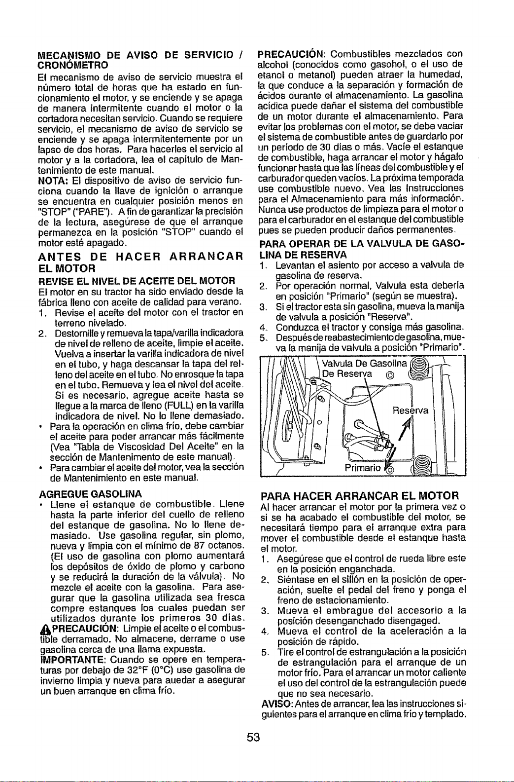
MECANISMO DE AVISO DE SERVtCIO I
CRONOMETRO
El mecanismo de aviso de servicio muestra el
nr_merototal de horas que ha estado en fun-
cionamiento el motor,y se enciende y se apaga
de manera intermitente cuando el motor o ta
cortadora necesitan servicioo Cuando se requiere
servicio, el mecanismo de aviso de servicio se
enciende y se apaga intermitentemente por un
lapso de dos horas. Para hacerles el servicio at
motor y a la cortadora, lea el capitulo de Man-
tenimiento de este manual.
NOTA: El dispositivo de aviso de servicio fun-
ciona cuando la Ilave de ignici6n o arranque
se encuentra en cualquier posici6n menos en
"STOP" ("PARE"). A fin de garantizar la precisi6n
de la lectura, asegurese de que el arranque
permanezca en la posici6n "STOP" cuando el
motor est6 apagado.
ANTES DE HACER ARRANCAR
EL MOTOR
REVISE EL NWEL DE ACEtTE DEL MOTOR
El motor en su tractor ha sido enviado desde la
f&brica Iteno con aceite de calidad para verano.
!. Revise el aceite det motor con el tractor en
terreno nivelado.
2. Destomille y remueva tatapa]varilla indicadora
de nivet de relleno de aceite, limpie et aceite.
Vuetva a insertarla varitla indicadora de nivel
en el tubo, y haga descansar ta tapa del rel-
leno del aceite en el tubooNo enrosque la tapa
en el tubo. Remueva y lea et nivel dei aceite.
Si es necesario, agregue aceite hasta se
ltegue a la marca de Ileno (FULL) en la varilla
indicadora de niveL No lo Ilene demasiado.
• Para la operaci6n en clima frfo, debe cambiar
el aceite para poder arrancar m&s f,_cilmente
(Vea "Tabla de Viscosidad Del Aceite" en la
secci6n de Mantenimento de este manua!)_
• Para cambiar el aceite de! motor, yea ta secci6n
de Mantenimiento en este manual.
AGREGUE GASOLINA
• Llene el estanque de combustible. Llene
hasta la parte inferior del cuelto de relleno
del estanque de gasolina. No to llene de-
masiado. Use gasolina regular, sin plomo,
nueva y limpia con el mlnimo de 87 octanos.
(El uso de gasolina con plomo aumentar_
los dep6sitos de 6xido de plomo y carbono
y se reducir& la duraci6n de la v&lvula). No
mezcle el aceite con ta gasolina. Para ase-
gurar que la gasolina utitizada sea fresca
compre estanques los cuales puedan ser
utilizados durante los primeros 30 dias,
tI_IPRECAL!CiC)N: Limpie el aceite o el combus-
e derramado. No almacene, derrame o use
gasolina cerca de una llama expuesta.
IMPORTANTE: Cuando se opere en tempera-
turas por debajo de 32°F (0°C) use gasolina de
invierno timpia y nueva para auedar a asegurar
un buen arranque en clima fifo.
PRECAUCION: Combustibles mezclados con
alcohol (conocidos como gasohol, o et uso de
etanot o metanol) pueden atraer la humedad,
la que conduce a la separaci6n y formaci6n de
&cidos durante et almacenamiento, La gasolina
acldica puede daftar el sistema det combustible
de un motor durante et almacenamiento, Para
evitar los problemas con el motor, se debe vaciar
el sistema de combustible antes de guardarlo por
un perfodo de 30 dias o m_.s.Vacie el estanque
de combustible, haga arrancar el motor y h&galo
funcionar hasta que las lineas del combustible y el
carburador queden vacioso La pr6xima temporada
use combustible nuevo_ Vea fas Instrucciones
para el Almacenamiento para m_.s informaci6n.
Nunca use productos de limpieza para el motor o
para et carburador en el estanque del combustible
pues se pueden producir da5os permanenteso
PARA OPERAR DE LA VALVULA DE GASO-
LINA DE RESERVA
1_ Levantan el asiento pot acceso a valvula de
gasolina de reserva.
2. Por operaci6n normal, Vatvula esta deberia
en posici6n "Primario" (segd=nse muestra).
3. Si el tractor esta sin gasolina, mueva ia manija
de vaivula a posici6n "Reserva".
4_ Conduzca el tractor y consiga m&s gasolinao
5. Despu_s de reabastecimiento de gasolina, mue-
va la manija de valvuta a posici6n "Primario".
Valvula De Gasolina
De Reserva @
Primario
PARA HACER ARRANCAR EL MOTOR
AI hacer arrancar et motor por la primera vez o
si se ha acabado e! combustible det motor, se
necesitar& tiernpo para el arranque extra para
mover el combustible desde el estanque hasta
el motor,.
1. Asegurese que el control de rueda libre este
en la posici6n enganchada.
2, Si_ntase en el sill6n en la posici6n de oper-
aci6n, suelte el pedal del freno y ponga el
freno de estacionamiento.
3. Mueva el embrague del accesorio a la
posici6n desenganchado disengaged.
4. Mueva el control de la aceleraci6n a la
posici6n de r&pido,
5. Tire el control de estrangulaci6n a la posici6n
de estrangulaci6n para el arranque de un
motor frio. Para el arrancar un motor caliente
el uso del control de la estrangulaci6n puede
que no sea necesarioo
AVISO: Antes de arrancar, lea las instrucciones si.-
guientes para e! arranque en clima frio y templado.
53
6. tnserte la Ilave en la ignici6n y glre ta Ilave
en el sentido que giran las maniUas del reloj
a la posici6n de arranque start, y suelte la
Itave tan pronto como arranque el motor_
No haga funcionar el arrancador continu-
amente por m_s de quince segundos pot
minuto. Si el motor no arranca despu6s
de varios intentarlos, mueva et control de
ia estrangulaci6n hacia adentro, espere
unos cuantos minutos y trate de nuevo. Si
el motor sigue sin funclonar, estire del con-
trol de la estrangulaci6n y trate de nuevo.
ARRANQUE CON TIEMPO TEMPLADO
(50°F/10°CY MAS)
7. Cuando arranque el motor, empuje el control
de la estrangulaci6n hasta que el motor emp-
iece a funcionar mbs suavemente. Si e! motor
empieza a funcionar mal, estire del control de
la estrangulaci6n un poco por unos cuantos
segundos y entonces continu_ a empujar
lentamente el control_
8. Los accesorios y el embrague de suelo ahora
puede ser utilizados. Si el motor no acepta
esta carga, vuelva a arrancar el motor para
permitirle que se caliente por un minuto,
utilizando el estrangulador como describido
arriba.
ARRANQUE CON TIEMPO FR[O (50°/10°C Y
MENOS)
9. Cuando arranque el motor,empuje lentamente
el control de ta estrangulaciSn hacia adentro
hasta que el motor empiece a funcionar
suavementeo Siga empuj&ndolo poco a poco
permitiendo que el motor acepte pequefios
cambios de velocidad y carga, hasta que este
comptetamente hacia adentro. Si el motor
empieza a funcionar real, estire del contro! de
ta estrangulaci6n un poco por uncs cuantos
segundos y continuea empujar el controlhacia
adentro. Esto puede requerir que el motor se
caliente por unos cuantos minutos, depende
de la temperatura.
CALENTAMIENTO PARA LA TRANSMISION
AUTOMATICA
Antes de conducir la unidad en un tiempo frfo, la
transmisi6n debe ser calentada como las instruc-
ciones siguientes:
1_ Aseg_rese que eitractor este situado en una
superficie nivelada.
2. Alivie elfreno de estacionamiento y deje que
el freno vuetva a la posici6n de operaci6n.
3. Permita que la transmisi6n se caliente du-
rante un minuto. Esto puede ser echo durante
el tiempo de calentamiento det motor.
4. Los accesofios pueden ser utilizados durante el
periodo del recalentamiento del motor despu_s
que ]atransmisi6n halla sido calentada y puede
requerir que el control de ta estrangulaci6n sea
estirado tin poco.
AVISO: Si se encuentra a mucha altura (sobre
3000 pies) o en clima frio (per debajo de 32°F
0°C), ta mezcla del combustible det carburador
debe ser ajustada para el mejor rendimiento del
motor. (Vea "PARA AJUSTAR EL CARBURA-
DOR" en la secci6n de Ser¢icio y Ajustes de
este manual).
RGAR LA TRANSMISION
PRECAUCl6N: Nunca enganche o desen-
ganche la palanca del control de rueda libre
cuando el motor esta funcionandoo
Para asegurar ta operaci6n y ejecuci6n adec-
uada, es recomendado que la transmisi6n sea
purgada antes de operar el tractor para ta prim-
era vez. Este proceso remover& cualquier aire
adentro de la transmisi6n que se halla formado
durante el transporte de su tractor_
IMPORTANTE= Si por acaso su transmisi6n debe
ser removida para servicio o reemplazo, debe
ser purgada despu_s de la reinstalaci6n y antes
de operar el tractor_
1_ Para mayor seguridad, ubique el tractor en
una superficie nivelada, despejada de cuat-
quier objeto y abierta, con el motor apagado
y el freno de mano puestoo
2_ Desenganche la transmisi6n poniendo el
control de rueda libre en la posici6n de desen-
ganchado (Vea "PARA EL TRANSPO RTE" en
esta secci6n de este manual).
3. Sentado en el asiento del tractor, empiece
el motor. Despu6s que este corriendo el mo-
tor, mueva el control de estrangulaci6n a la
,_q posici6n de lento. Quitar el freno de mano_
PRECAUCION: En el transcurso del paso 4,
puede que de pronto se pongan en movimiento
las ruedas,
4. Apretar el pedal de marcha adelante hasta
el fondo, mantener por cinco (5) segundos y
soltar el pedal. Apretar et pedal de marcha
atr,_s hasta el fondo, mantener por cinco (5)
segundos y soltar el pedal. Repetir el proced-
imiento tres (3) veces.
5. Apague el motor y embrague el freno de
estacionamiento.
6. Enganche la transmisi6n poniendo el control
de rueda tibre en la posici6n de conducir (Vea
"PARA TRANSPORTAR" en esta secci6n del
manual).
7+ Sentado en et asiento det tractor, empiece et
motor. Despu_s que este corriendo el motor,
mueva el control de estrangulaci6n media
(1/2) velocidad_ Quitar el freno de mano
8. Conduzca su tractor hacia adelante durante
aproximadamente cinco pies y entonces ha-
cia marcha atr&s cinco pies (150 cm). Repita
este proceso tres (3) veces.
Su transmisi6n esta ahora purgado y dispuesto
para fa operaci6n normal.
54
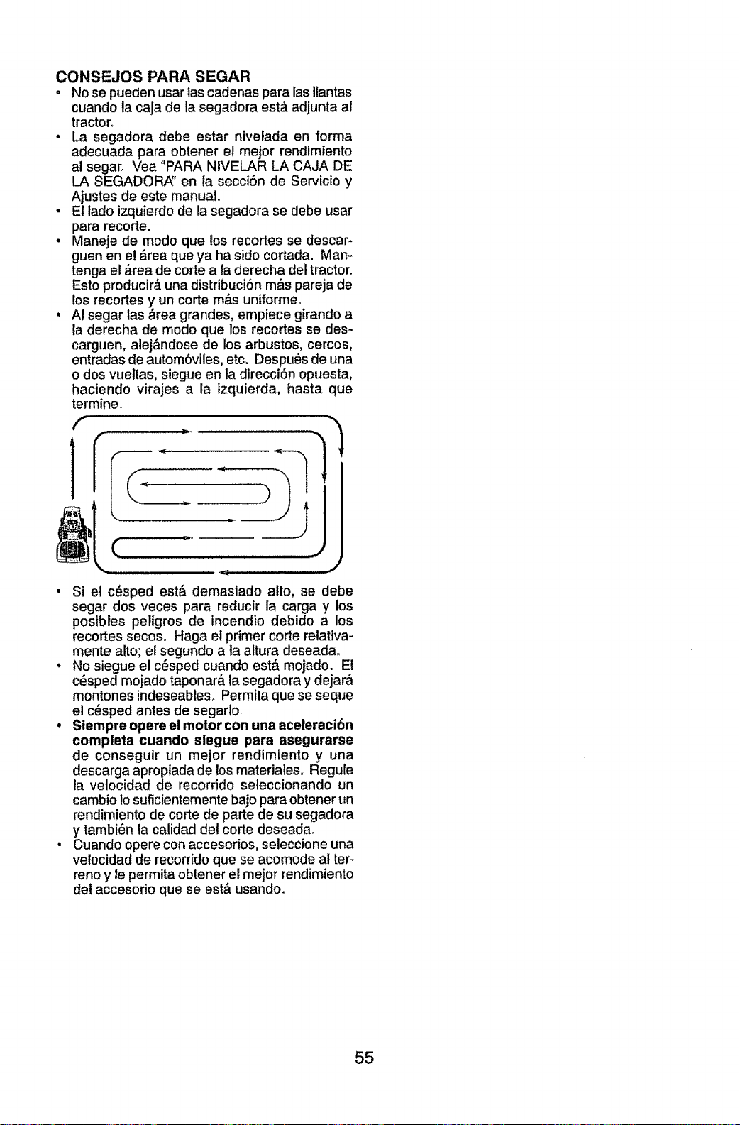
CONSEJOS PARA SEGAR
. No se pueden usar tas cadenas para las Ilantas
cuando la caja de la segadora est_ adjunta a!
tractor.
• La segadora debe estar nivelada en forma
adecuada para obtener et mejor rendimiento
al segan Vea "PARA NIVELAR LA CAJA DE
LA SEGADOR,_' en la secci6n de Servicio y
Ajustes de este manual.
• Et tado izquierdo de la segadora se debe usar
para recorte.
• Maneje de modo que los recortes se descar-
guen en el &rea que ya ha sido cortada. Man-
tenga el b,rea de corte a la derecha del tractor.
Esto producir& una distribuci6n m_s pareja de
los recortes y un corte m&s uniforme_
, AI segar las &rea grandes, empiece girando a
la derecha de modo que los recortes se des-
carguen, alej_,ndose de los arbustos, cercos,
entradas de autom6viles, etc. Despu6s de una
o dos vueltas, siegue en la direcci6n opuesta,
haciendo virajes a la izquierda, hasta que
termineo
f
I"
,.J
• Si e! c6sped est& demasiado alto, se debe
segar dos veces para reducir la carga y los
posibtes peligros de incendio debido a los
recortes secos. Haga et primer corte relativa-
mente alto; el segundo a la altura deseadao
• No siegue el c6sped cuando est,, mojado. Et
c6sped mojado taponar& ta segadora y dejar&
montones indeseables. Permita que se seque
el c6sped antes de segarlo.
• Siempre opere el motor con una aceleracibn
compteta cuando siegue para asegurarse
de conseguir un mejor rendimiento y una
descarga apropiada de los materialeso Regule
la velocidad de recorrido seleccionando un
cambio Io suficientemente bajo para obtener un
rendimiento de corte de parte de su segadora
y tambi6n la calidad del corte deseada.
, Cuando opere con accesorios, seleccione una
velocidad de recorrido que se acomode al ter-
reno y le permita obtener el mejor rendimiento
del accesorio que se est& usando.
55
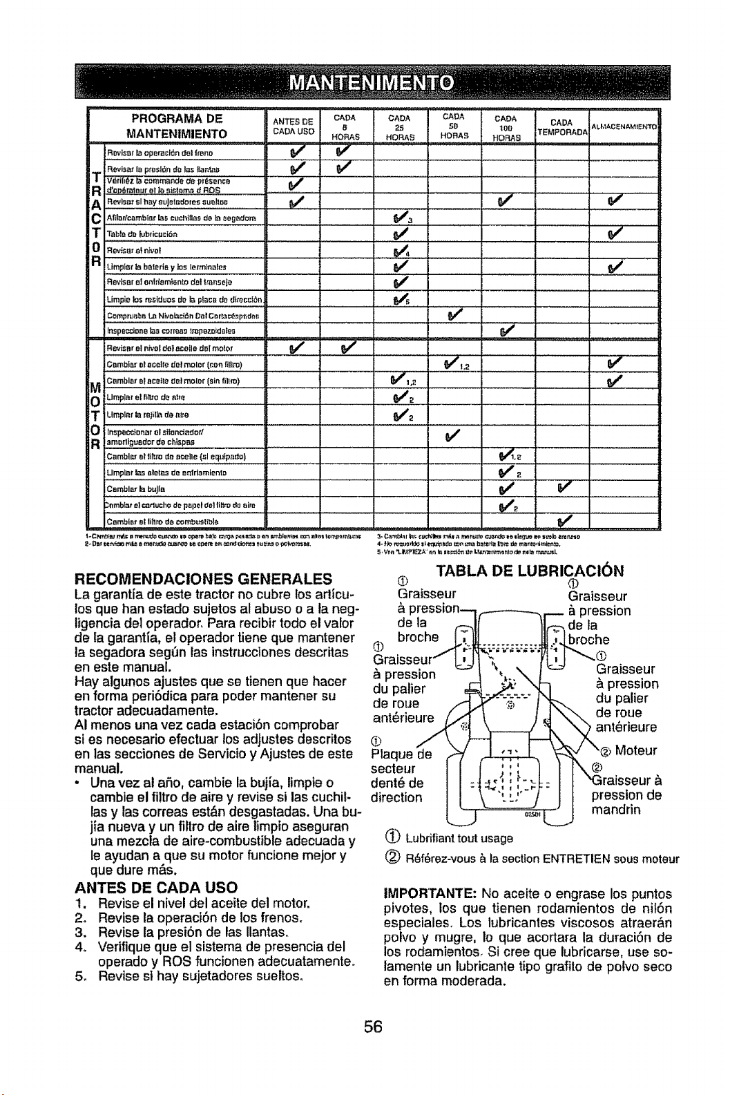
PROGRAMA DE ANTESDE
MANTENIMIENTO CAD^USe
CADA CADA GADA CADA CADA
8; 25 5D _00 TEMPORADAi
HORAS HORAS HORA._ HOFIA8
s_i_ar _ operation_1 fmno _
Rovi_,_r I_ ptos|_n de I_s tlan_as
T Vdrifl6z b i¢_mm_nde _e presence _€
R d'ep_m aur qi"_ _i_ Dm_ _ RO8
A Revi,ar t;Ih_y su_et_doms su_Bor; _ {_
C Afflaffcambiar b.s cuch_g,_sde _ oeg_dom _3
T "TabI_de _bricaci6n
0 RevlsarelnJvo[ ........
Rev_sr e! ent_{em_snto dal Iranseto
Limpie los residues Ire t,:_pl_ca do di_'occ_6n _5
Compeat_bn L_ 'Nk,ol_c{_n Or_lCor_'_c_sp_d_r,
!
v'
v'
Inspecctone I_s co:rr_s _mpezoida|es
Cambisr ot ,a¢elle dol meier' (cOn fillm) _h2 _, ........
0 _i._p_iO_ioi_iiO_o_ " "
R :omr_rtigua_vr do chtspns ,, ...................
LlmplJ_r_ aletaS de enfd,emient_ _ 2
€,.,b,_._,b._!o..................................................... _ .... _ ........
.-rnrnbiae'el caflucho de pepot dot Iliumdo aim _g
v"
TABLA DE LUBRICACI_N
® ®
Graisseur Graisseur
_lpression
de la de la
broche broche
pression Graisseur
du palier & pression
de roue du palier
de roue
ant6rieure ant6rieure
Cambir_t el lillm do combusllbl_
Moteur
@
pression de
mandrin
t_ Lubrifiant tout usage
(_) R_f_rez-vous & la section ENTRETIEN sous moteur
RECOMENDACIONES GENERALES
La garantia de este tractor no cubre los articu-
los que han estado sujetos al abuse o a la neg-
ligencia del operador, Para recibir todo el valor
de la garant{a, el operador tiene que mantener
la segadora seg(Jn las instrucciones descritas
en este manual.
Hay algunos ajustes que se tienen que hacer
en forma periSdica para poder mantener su
tractor adecuadamente.
AI menos una vez cada estaci6n comprobar
si es necesario efectuar los adJustes descritos
en las secciones de Servicio y Ajustes de este Pla_
manual, secteur
• Una vez at afio, cambie la buj_a, limpie o dent6 de
cambie el filtro de aire y revise si las cuchil- direction
las y las correas est&n desgastadas. Una bu-
jia nueva y un filtro de aire limpio aseguran
una mezcla de aire-combustible adecuada y
le ayudan a que su motor funcione meier y
que dure mas.
ANTES DE CADA USO
t. Revise el nivel del aceite del motor.
2. Revise la operaci6n de los frenos.
3. Revise ia presi6n de las Ilantas_
4o Vefifique que el sistema de presencia del
operado y ROS funcionen adecuatamente,,
5. Revise si hay sujetadores sueltos.
IMPORTANTE: No aceite o engrase los puntos
pivotes, los que tienen rodamientos de nif6n
especiales. Los lubricantes viscosos atraer&n
polvo y mugre, Io que acortara la duraci6n de
los rodamientos, Si cree que lubricarse, use so-
lamente un lubricante tipo grafito de polvo seco
en forma moderada.
56
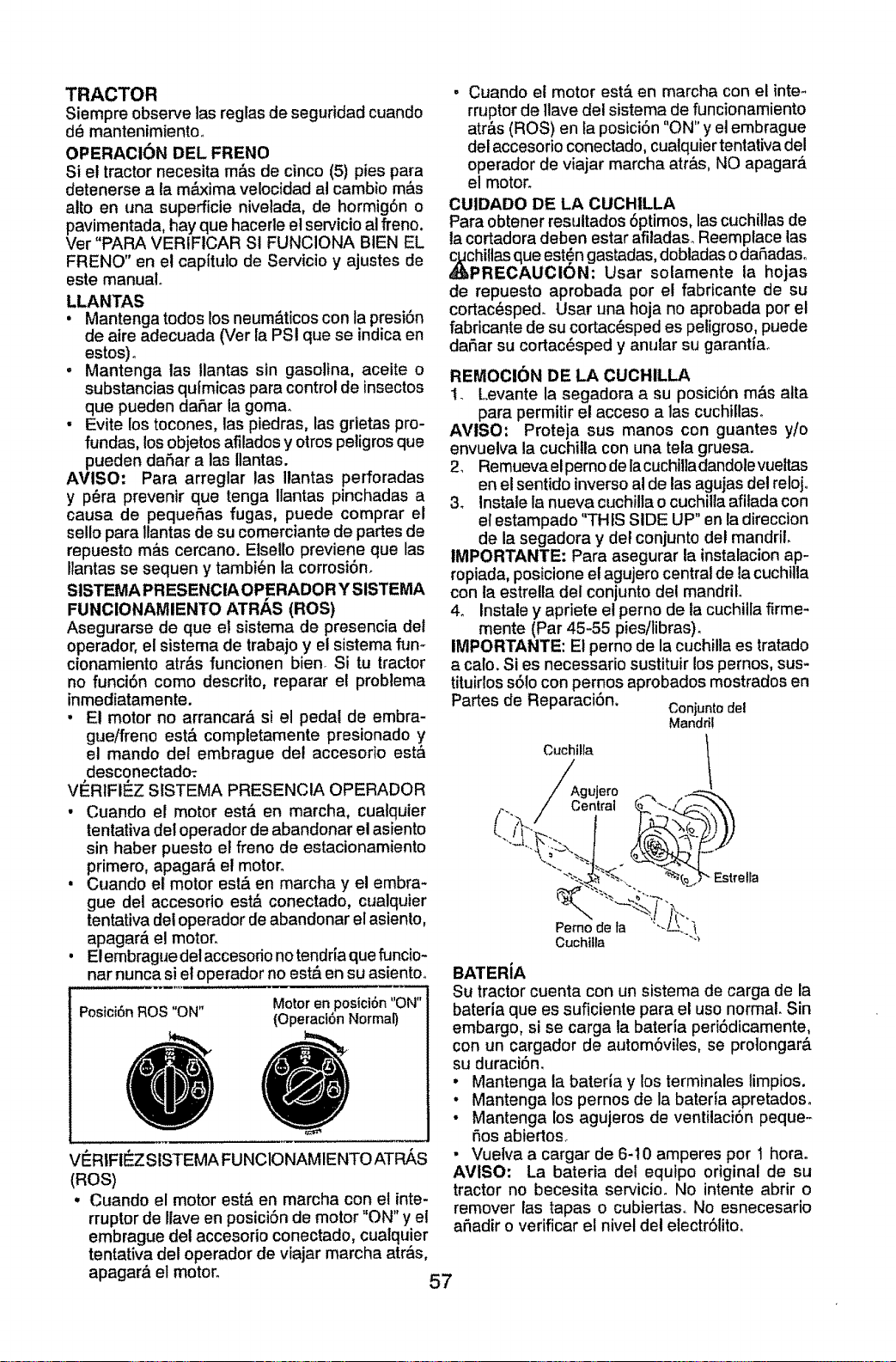
TRACTOR
Siempre observe las reglas de seguridad cuando
d_ mantenimiento.
OPERACION DEL FRENO
Si el tractor necesita m&s de cinco (5) pies para
detenerse a la m_b,dma velocidad al cambio m&s
alto en una superficie nivelada, de hormig6n o
pavimentada, hay que hacerle el servicio al freno.
Ver "PARA VERIFICAR SI FUNCIONA BIEN EL
FRENO" en el capitulo de Servicio y ajustes de
este manual°
LLANTAS
• Mantenga todos los neum&ticos con la presi6n
de aire adecuada (Ver la PSI que se indica en
estos)_
, Mantenga las !lantas sin gasolina, aceite o
substancias qufmicas para control de insectos
que pueden dafiar la goma.
• Evite los tocones, las piedras, las grietas pro-
fundas, losobjetos afilados y otros peligros que
pueden dafiar alas llantas.
AVISO: Para arreglar las Ilantas perforadas
y p_ra prevenir que tenga Ilantas pinchadas a
causa de pequefias fugas, puede comprar el
sello para llantas de su comerciante de partes de
repuesto m#,s cercano. Etsello previene que las
Itantas se sequen y tambi_n la corrosi6n.
SISTEMAPRESENCIA OPERADOR YSISTEMA
FUNCIONAMIENTO ATR/_S (ROS)
Asegurarse de que el sistema de presencia det
operador, el sistema de trabajo y el sistema rum
cionamiento arras funcionen bien Si tu tractor
no funci6n como descrito, reparar el problema
inmediatamente.
, E! motor no arrancar& si el pedal de embra-
gue/freno est,, completamente presionado y
el mando del ernbrague del accesorio esta
desconectadm
VERIFIF:Z StSTEMA PRESENCIA OPERADOR
• Cuando el motor est& en marcha, cualquier
tentativa del operador de abandonar el asiento
sin haber puesto et freno de estacionamiento
primero, apagar& el motor_
• Cuando el motor est& en marcha y el embra-
gue del accesofio est,_ conectado, cualquier
tentativa del operador de abandonar el asiento,
apagar& el motor.
• Elembrague delaccesodo no tendria que funcio-
nar nunca si el operador no est& en su asientoo
Posici6n ROS "ON" Motoren posici6n"ON"
(Operacibn Normal)
, Cuando el motor est_ en marcha con el inte*
rruptor de llave del sistema de funcionamiento
atr&s (ROS) en la posici6n "ON"y el embrague
del accesorio conectado, cualquier tentativa del
operador de viajar marcha atr&s, NO apagar&
el motor.
CUIDADO DE LA CUCHILLA
Para obtener resultados 6ptimos, las cuchitlasde
la cortadora deben estar afiladas_Reemplace las
Cphiltasque est_n gastadas, dobladaso dafiadaso
RECAUCION: Usar sotamente la hojas
de repuesto aprobada por e! fabricante de su
cortac_sped. Usar una hoja no aprobada por el
fabricante de su cortac_sped es peligroso, puede
dafiar su cortac_sped y anular su garantiao
REMOCION DE LA CUCHILLA
I. Levante la segadora a su posici6n m&s alta
para permitir el acceso a las cuchillaso
AMISO: Proteja sus manos con guantes yio
envueiva la cuchitla con una tela gruesa.
2, Remueva elperno de la cuchilla dandole vueltas
en el sentido inverso al de las agujas del reloj_
3. Instale la nueva cuchilla o cuchilta afifada con
el estampado "THIS SIDE UP" en la direccion
de la segadora y def conjunto del mandril.
IMPORTANTE: Para asegurar la instalacion ap-
ropiada, posicione el agujero central de la cuchitla
con la estrella del conjunto del mandril
4. Instale y apriete el perno de la cuchilla firme-
mente (Par 45-55 pies/libras)o
IMPORTANTE: El perno de la cuchilla es tratado
a calo, Si es necessario sustituir lospernos, sus-
tituirlos s61ocon pernos aprobados mostrados en
Partes de Reparaci6n. Conjuntodel
Mandr_!
Cuchi_la 1
Agujero _
Pemo de ta "'-
Cuchtlla -"_
VI_RIFiI_Z SISTEMA FUNCIONAMIENTO ATR/_.S
(ROS)
• Cuando el motor est& en marcha con el inte-
rruptor de Ilave en posici6n de motor "ON" y el
embrague del accesorio conectado, cualquier
tentativa del operador de viajar marcha air&s,
BATERiA
Su tractor cuenta con un sistema de carga de la
bateria que es suficiente para el uso normal. Sin
embargo, si se carga la bateria peri6dicamente,
con un cargador de autom6viies, se protongar&
su duraci6n.
• Mantenga la bateria y los terminales limpios.
• Mantenga los pernos de la bateria apretados.
• Mantenga los agujeros de ventilaci6n peque.-
fios abiertos_
• Vuelva a cargar de 6-t0 amperes pot t hora°
AMISO: La bateria del equipo original de su
tractor no becesita servicio. No intente abrir o
remover las tapas o cubiertas. No esnecesario
afiadir o verificar el nivel del electr61ito,
apagar& el motor°
57
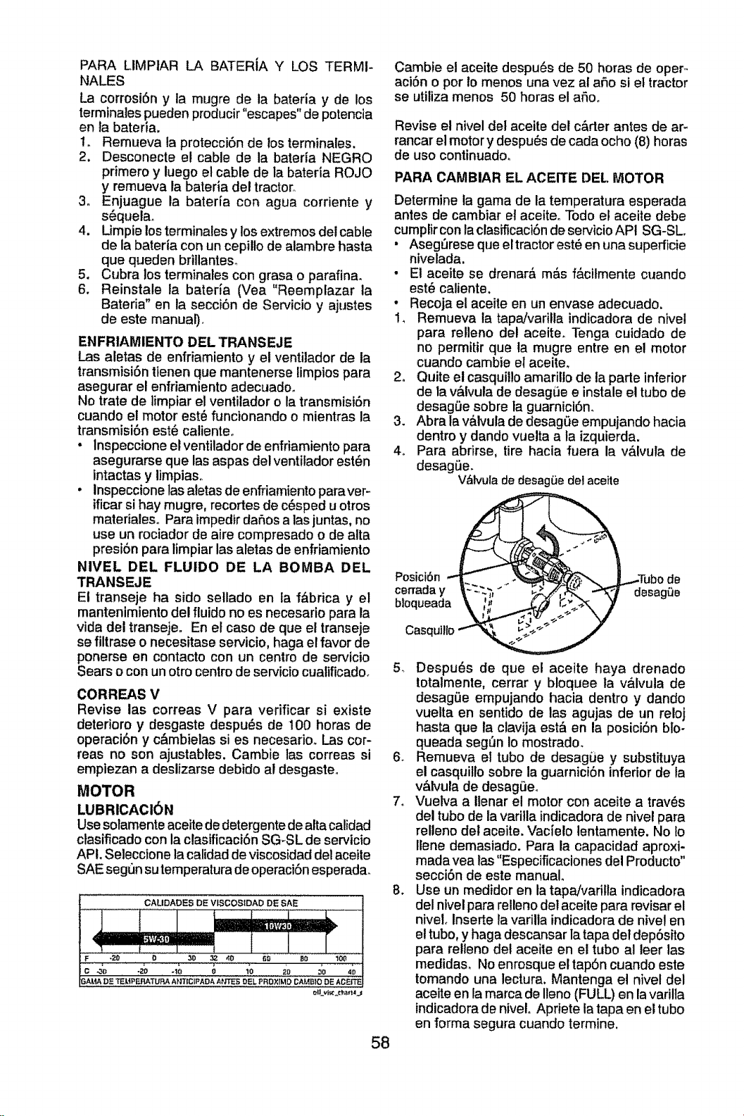
PARA LIMPIAR LA BATERiA Y LOS TERMI-
NALES
La corrosi6n y ta mugre de ta bateria y de los
terminales pueden producir"escapes" de potencia
en la bateria.
t_ Remueva ta protecci6n de los terminales.
2. Desconecte el cable de la bateria NEGRO
pdmero y tuego el cable de la bateria ROJO
y remueva la bateria del tractor.
3, Enjuague la baterla con agua corriente y
s_quelao
4. Limpie los terminales y los extremos del cable
de la bateria con un cepillo de alambre hasta
que queden brillanteso
5. Cubra los terminales con grasa o parafina.
6. Reinstale la baterla (Vea "Reemplazar la
Bateria" en ta secci6n de 8ervicio y ajustes
de este manual),
ENFRIAMIENTO DELTRANSEJE
Las aletas de enfriamiento y el ventitador de ia
transmisi6n tlenen que mantenerse fimpios para
asegurar el enfriamtento adecuado.
No trate do limpiar el ventilador o la transmisi6n
cuando el motor est6 funcionando o mientras la
transmisi6n est6 calienteo
• lnspeccione el ventiladorde enfriamiento para
asegurarse que Ins aspas del ventilador est_n
intactas y limpiaso
• inspeccionelas atetasde enfriamiento paraver-
ificar si hay rnugre, recortes de c6sped u otros
materialeso Para impedtrdafios a Insjuntas, no
use un rociador de aire compresado o de alta
presi6n para limpiar Ins aletas de enfriamiento
NIVEL DEL FLUIDO DE LA BOMBA DEL
TRANSEJE
El transeje ha sido setlado en ta f_brica y el
mantenimiento del fluido no es necesario para la
vida del transeje° En el caso do que el transeje
se filtrase o necesitase servicio, haga el favor de
ponerse en contacto con un centro de servicio
Sears o con un otro centro de servicio cuatificadoo
CORREAS V
Revise Ins correas V para verificar si existe
deterioro y desgaste despuL_s de 100 horas de
operaci6n y c&mbielas si es necesario. L.ascor-
reas no son ajustables. Cambie ins correas si
empiezan a deslizarse debido al desgaste,
MOTOR
LUBRICACI6N
Use solamente aceite de detergente de alta calidad
ctasificadocon la clasificaci6n SG-SL de servicio
AP!. Seleccione la calidad de viscosidaddelaceite
SAE segun su temperaturade operaciSnesperada.
CAUDADES DE VISCOStDAD DE SAE
F _'_ o.........................._o' _ _o _ ' _0 ' i00 ......
c -_ ._o 40 o lo io _o ,_
G,AL_ DE TEUP F..RATURAA;q'i'|C|PAD&At"_ OEL PROXIMO CAMBIO DE ACEFF_I
58
Cambie el aceite despu6s de 50 horas de oper-
aci6n o por Io menos una vez al afio si el tractor
se utiliza menos 50 horas el afioo
Revise el nivel del aceite det c&rter antes de ar-
rancar el motor y despu_s de cada ocho (8) horas
de uso continuadoo
PARA CAMBIAR EL ACEITE DEL MOTOR
Determine ta gama de la temperatura esperada
antes de cambiar el aceiteo Todo e! aceite debe
cumplir con la clasificaci6n de servicio API SG-SL.
• Aseg_rese que el tractor est6 en una supefficie
nivelada,
• Et aceite se drenar& m&s f&cilmente cuando
est6 caliente,
• Recoja el aceite en un envase adecuado,
1_ Remueva la tapa/varilla indicadora de nivel
para relleno del aceite, Tenga cuidado de
no permitir que la mugre entre en el motor
cuando cambie el aceite,
2o Quite el casquillo amarillo de la parle inferior
de la v&lvula de desagLie e instale el tubo de
desagL_esobre la guarnici6n,
3, Abra ta v&bJulade desag0e empujando hacia
dentro y dando vuelta a ta izquierda.
4. Para abrirse, tire hacia fuera la v&lvula de
desag_e.
V&lvulade desagLiedel aceite
PosiciSn
ce_aday
bloqueada
Casqu]llo
desagQe
5, Despu6s de que el aceite haya drenado
totalmente, cerrar y bloquee la v&lvula de
desag_Je empujando hacia dentro y dando
vuelta en sentido de Ins agujas de un reloj
hasta que ta clavija est& en la posici6n blo-
queada seg_n Io mostrado,
6_ Remueva et tubo de desagLie y substituya
el casquillo sobre la guarniciSn infedor de la
v&lvula de desag0eo
7. Vuelva a Ilenar el motor con aceite a trav_s
del tube de la varitla indicadora de nive! para
relleno det aceite. Vacie!o lentamente. No fo
Ilene demasiado. Para la capacidad aproxi-
madavea las"Especificaciones del Producto"
secci6n de este manual,
8. Use un medidor en la tapa/varitla tndicadora
del nivel para relleno del aceite para revisar el
nivel, Inserte la varilla indicadora do nivel en
el tubo, y haga descansar la tapa del dep6sito
para relteno det aceite en el tubo al leer tas
medidas. No enrosque el tapSn cuando este
tomando una lectura. Mantenga e! nivel del
aceite en la marca de Ileno (FULL) en la varilla
indicadora de niveL Apfiete fa tapa en et tubo
en forma segura cuando termine,
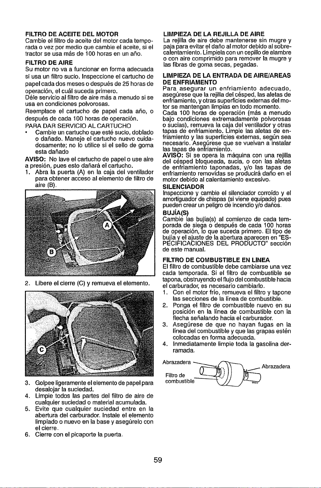
FILTRO DE ACEtTE DEL MOTOR
Cambie el filtro de aceite det motor cada tempo-
rada ovez por medio que cambie el aceite, si el
tractor se usa m&s de !00 horas en un aSo,
FILTRO DE AIRE
Su motor no va a funcionar en forma adecuada
si usa un filtro sucio, lnspeccione el cartucho de
papel cada dos meses o despu_s de 25 horas de
operaci6n, el cu_l suceda primero,
D_le sepJicio at filtro de aire m_s a menudo si se
usa en condiciones polvorosas.
Reemplace el cartucho de papel cada aSo0 o
despu6s de cada 100 horas de operaci6n.
PARA DAR SERVtCIO AL CARTUCHO
, Cambie un cartucho que est_ sucio, doblado
o daSado. Maneje el cartucho nuevo cuida-
dosamente; no Io utilice si el sello de goma
esta dafiado
AVISO: No lave el cartucho de papel o use aire
a presi6n, pues esto dafiar,_ el cartucho.
I. Abra la puerta (A) en la caja del ventilador
para obtener acceso al elemento de filtro de
aire (B)_
2, Libere el cierre (C) y remueva e! etemento.
3, Golpee ligeramente el elemento de pape! para
desatojar ta suciedad.
4, Limpie todos las partes del fiitro de aire de
cualquier suciedad o material acumuladao
5. Evite que cualquier suciedad entre en la
abertura det carburadoro lnstale el elemento
limpiado o nuevo en ta base y aseg_re!o con
et cierre,
6, Cierre con el picaporte la puerta,
LIMPIEZA DE LA REJILLA DE AIRE
La rejilla de aire debe mantenerse sin mugre y
paja para evitar el dar_o al motor debido al sobre-
calentamiento, Ltmpiela con un cepillo de alambre
o con aire comprimido para remover ta mugre y
las fibras de goma secas, pegadas.
LIMPIEZA DE LA ENTRADA DE AIRE/AREAS
DE ENFRIAMENTO
Para asegurar un enfriamiento adecuado,
asegerese que la rejilla del c_sped, las aletas de
enfriamiento, y otras superficies externas del mo-
tor se mantengan limpias en todo momento.
Cada 100 horas de operaci6n (rods a menudo
bajo condiciones extremadamente potvorosas
o sucias), remueva la caja del ventilador y otras
tapas de enfriamiento. Limpie ias aletas de en-
friamiento y las superficies extemas, segSn sea
necesariooAsegerese que se vuelvan a instafar
las tapas de enfriamiento.
AVISO: Si se opera la maquina con una rejilla
del c6sped btoqueada, sucia, o con las aletas
de enfriamiento taponadas, y/o las tapas de
enfriamiento removidas se producir& daSo en el
motor debido al calentamiento excesivo.
SILENClADOR
Inspeccioney cambie el silenciador corroidoy el
amortiguador de chispas (si viene equipado) pues
puedencrear unpeligrode incendio y/o daSos.
BUJiA(S)
Cambie las bujia(s) al comienzo de cada tem-
porada de siega o despu_s de cada 100 horas
de operaciSn, Io que suceda primero. El tipo de
bujia y et ajuste de la abertura aparecen en "ES-
PECIFICACIONES DEL PRODUCTO" secci6n
de este manual
FILTRO DE COMBUSTIBLE EN LINEA
El filtro de combustible debe cambiarse una vez
cada temporadao Si et filtro de combustible se
tapona, obstruyendo el flujo del combustiblehacia
el carburador, es necesario cambiarloo
1o Con el motor frio, remueva el filtro y tapone
las secciones de la tinea de combustible°
2. Ponga el filtro de combustible nuevo en su
posici6n en la ttnea de combustible con la
flecha seP,alando hacia el carburadoro
3_ Aseg_rese de que no hayan fugas en la
linea del combustible y que las grapas est6n
cotocadas en forma adecuada.
4. Inmediatamente limpie toda la gasolina der-
ramada.
Abrazadera --._/,"_,_
combustible _y _'-_
59
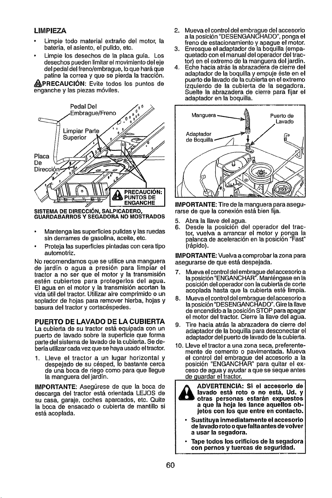
LIMPIEZA
. Limpie todo material extrafio del motor, la
bateria, el asiento, el pulido, etc_
. Limpie los desechos de la placa guia. Los
desechos pueden limitar el movimiento del eje
del pedal del freno/embrague, Io que har& que
patine la correa y que se pierda la tracci6n,
_PRECAUCI6N: Evite todos los puntos de
enganche y las piezas m6viles.
Pedal Del
ue/Freno
Placa
De
Direcci6n¢
\
ENGANCHE
SISTEMA DE DIRECCI6N, SALP1CADERO,
GUARDABARROS Y SEGADORA NO MOSTRADOS
• Mantenga las superficies pulidas y las ruedas
sin derrames de gasolina, aceite, etc.
• Proteja las superficies pintadas con cera ttpo
automotriz.
No recomendamos que se utilice una manguera
de jardin o agua a presi6n para limpiar el
tractor a no ser que el motor y la transmisi6n
est_n cubiertos para protegerlos det agua.
E1agua en et motor y ia transmisi6n acortan la
vida t_tildel tractor. Utilizar aire comprimido o un
soplador de hojas para remover hierba, hojas y
basura del tractor y cortac_spedeso
PUERTO DE LAVADO DE LA CUBIERTA
La cubierta de su tractor estb equipada con un
puerto de lavado sobre la superficie que forma
parte del sistema de lavado de la cubierta. Se de-
beria uttlizarcada vez quese haya usadoel tractor.
t. Lteve el tractor a un tugar horizontal y
despejado de su c6sped, Io bastante cerca
de una boca de riego como para que Ilegue
la manguera del jardfm
IMPORTANTE: AsegSrese de que la boca de
descarga del tractor est& orientada LEJOS de
su casa, garaje, coches aparcados, etc. Quite
la boca de ensacado o cubierta de manti!to si
est& acopladao
2. Mueva el control del embrague del accesorio
a ta posici6n "DESENGANCHADO", ponga el
freno de estacionamiento y apague el motor°
3. Enrosque el adaptador de la boquitla (empa-
quetado con el manual del operador del trac-
tor) en el extremo de la manguera del jardin.
4. Eche hacia atr&s la abrazadera de cierre del
adaptador de la boquitla y empuje _ste en el
puerto de lavado de la cubierta en el extremo
izquierdo de ta cubierta de ta segadora.
Suelte la abrazadera de cterre para fijar el
adaptador en la boquilta.
Manguera Puerto de
Lavado
Adaptador
de Boc
IMPORTANTE: Tire de la manguera para asegu-
rarse de que la conexi6n est& bien fija_
.
6_
Abra ta Ilave del agua.
Desde la posici6n det operador dei trac-
tor, vuelva a arrancar el motor y ponga la
palanca de aceleraci6n en la posici6n "Fast"
(r&pido).
IMPORTANTE: Vuelva a comprobarla zona para
asegurarse de que est& despejada.
7. Mueva el control det embrague del accesorio a
la posici6n "ENGANCHAR". Mant6ngase en la
posici6n del operador con la cubierta de corte
acoplada hasta que la cubierta est6 limpia.
8o Mueva el control det embrague det accesorio a
laposici6n"DESENGANCHADO". Gire la tlave
de encendido a la posici6n STOP para apagar
e! motor del tractor. Cierre la Ilave del agua_
9. Tire hacta atr&s la abrazadera de cierre del
adaptador de ta boquilla para desconectar el
adaptador del puerto de lavado de la cubierta,
10. Lleve el tractor a una zona seca, preferente-
mente de cemento o pavimentada. Mueva
el control del embrague det accesorio a la
posici6n "ENGANCHAR" para quitar el ex_,
ceso de agua y ayudar a que se seque antes
de guardar el tractor.
_ ADVERTENCIA: St el accesorlo de
lavado estb roto o no est,_, Ud. y
otras personas estar&n expuestos
a que la hoja les lance aquellos ob-
jetos con los que entre en contacto.
• Sustituya inmediatamente el accesorio
de lavado roto o que falta antes de volver
a usar la segadora.
• Tape todos los orificios de la segadora
con pernos y tuercas de segurldad.
6O
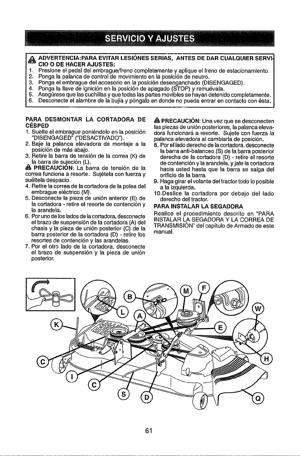
ADVERTENCIA:PARA EVITAR LESIONES SERIAS, ANTES DE DAR CUALQUIER SERV
CIO O DE HACER AJUSTES:
t, Presione el pedal del embrague/freno completamente y aptique el freno de estacionamientoo
2. Ponga la palanca de control de movimlento en la posici6n de neutro.
3. Ponga et embrague del accesorio en la posici6n desenganchado (DISENGAGED).
47 Ponga la llave de ignici6n en la posici6n de apagado (STOP) y remu_vala,
5, Asegt)rese que las cuchillas y que todas las partes movibles se hayan detenido completamenteo
6. Desconecte el atambre de la bujia y p6ngalo en donde no pueda entrar en contacto con _sta.
PARA DESMONTAR LA CORTADORA DE
ClaSPED
1oSuelte el embrague poni6ndolo en la posici6n
"DISENGAGED" ("DESACTIVADO").
2. Baje la palanca elevadora de montaje a la
posici6n de m&s abajo.
3. Retire la barra de tensi6n de la correa (K) de
la barra de sujeci6n (L).
PRECAUOtON: La barra de tensi6n de la
correa funciona a resorte° Suj6teta con fuerza y
su61tela despacio,
4_ Retire la correa de la cortadora de la polea det
embrague el6ctrico (M).
5. Desconecte la pieza de uniSn anterior (E) de
la cortadora - retire el resorte de contenci6n y
la arandela.
6,, Por uno de los tados de la cortadora, desconecte
el brazo de suspensi6n de la cortadora (A) del
chasis y la pieza de uni6n posterior (C) de la
barra posterior de ia cortadora (D) - retire los
resortes de contenci6n y las arandelaso
7. Pot el otto lado de ta cortadora, desconecte
el brazo de suspensiSn y la pieza de unf6n
posterior.
AI_PRECAUCION: Una vez que se desconecten
las piezas de uni6n posteriores, ta palanca eleva-
dora ftmcionar& a resorte. Sujete con fuerza la
palanca elevadora at cambiarla de posicl6n.
8. Por el tado derecho de la cortadora, desconecte
la barra anti-balanceo (S) de la barra posterior
derecha de la cortadora (D) - retire et resorte
de contenci6n y la arandela, yjale la cortadora
hacia usted hasta que la barra se salga del
ofificio de la barra.
9. Haga girar el volante del tractor todo Io posible
a la izquierda.
t0.Deslice ta cortadora por debajo del lado
derecho del tractor.
PARA INSTALAR LA SEGADORA
Realice el procedimiento descrito en "PARA
INSTALAR LA SEGADORA Y LA CORREA DE
TRANSMISION" del capitulo de Armado de este
manual.
6t
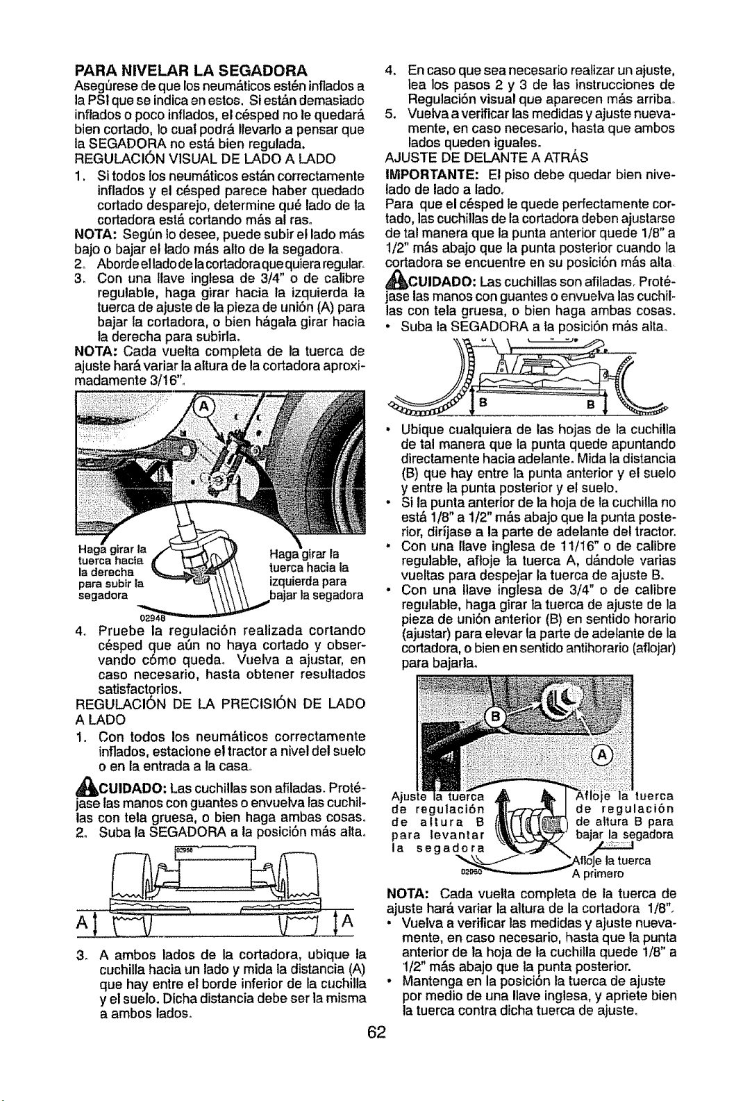
PARA NIVELAR LA SEGADORA
Aseg_rese de que los neum&ticos est_n inflados a
la PSI que se indica en estos. Si est&n demasiado
inflados o poco inflados, el c_sped no le quedar_.
bien cortado, lo cuat podr& Ilevarlo a pensar que
la SEGADORA no est_ bien regulada.
REGULAClON VISUAL DE LADO A LADO
1, Si todos los neum&ticos est&n correctamente
inflados y el c_sped parece haber quedado
cortado desparejo, determine qu_ lado de ta
cortadora est& cortando m_s al ras,,
NOTA: SegOn Io desee, puede subir el lado m_s
bajo o bajar el iado m&s allo de la segadora,
2. Aborde el lado dela cortadora que quiera regular,
3. Con una ltave inglesa de 3/4" o de calibre
regulabte, haga girar hacia la izquierda ta
tuerca de ajuste de la pieza de uni6n (A) para
bajar la cortadora, o bien h&gala girar hacia
la derecha para subirla.
NOTA; Cada vuetta completa de la tuerca de
ajuste har& variar la altura de la cortadora aproxi-
madamente 3/16".
tuBrca hacia irar la
la derecha tuerca hacia la
para subir ta izquierda para
segadora bajar la segadora
4o Pruebe la regulaci6n realizada cortando
c_sped que a6n no haya cortado y obser-
vando c6mo queda. Vuelva a ajustar, en
caso necesario, basra obtener resultados
satisfactorios.
REGULACI6N DE LA PRECISI6N DE LADO
A LADO
t. Con todos los neum&ticos correctamente
inflados, estacione et tractor a nivel del suelo
o en la entrada a la casa,
_CUIDADO: Las cuchillas son afiladas. Prot6-
jase las manos con guantes o envuelva las cuchil-
las con teta gruesa, o bien haga ambas cosas.
2. Suba la SEGADORA a la posici6n m&s alta,
. A ambos lados de la cortadora, ubique la
cuchilla hacia un lado y mida fa distancia (A)
que hay entre el borde inferior de la cuchilla
y el suelo. Dicha distancia debe ser la misma
a ambos lados.
62
4. En caso que sea necesario realizar un ajuste,
lea los pasos 2 y 3 de las instrucciones de
Regulaci6n visual que aparecen m&s arribao
5. Vuelva a verificar las medidas y ajuste nueva-
mente, en caso necesario, hasta que ambos
lados queden iguales°
AJUSTE DE DELANTE A ATR_,S
IMPORTANTE: El piso debe quedar bien nive-
tado de lado a lado.
Para que el c6sped le quede perfectamente cor-
tado, las cuchillas de la cortadora deben ajustarse
de tal manera que la punta anterior quede l/B" a
1/2" m_s abajo que ta punta posterior cuando la
cortadora se encuentre en su posici6n m&s alla,
_CUIDADO, Las cuchillas son afiladas. Prot_-
jase ias manos con guantes o envuelva las cuchit-
las con teta gruesa, o bien haga ambas cosas.
. Suba la SEGADORA a ta posici6n m_s alta.
B B
• Ubique cualquiera de las hojas de la cuchiila
de tal manera que la punta quede apuntando
directamente hacia adelante. Mida la distancia
(B) que hay entre la punta anterior y et suelo
y entre la punta posterior y el suelo.
- Si ta punta anterior de la hoja de la cuchilla no
est& 1/8" a 1!2" m&s abajo que la punta poste-
rior, dirijase a la parte de adelante del tractor.
. Con una tlave inglesa de 11/16" o de calibre
regulable, afloje ta tuerca A, d&ndole varias
vueltas para despejar la tuerca de ajuste B.
• Con una llave ingtesa de 3/4" o de calibre
regulable, haga girar ta tuerca de ajuste de la
pieza de uni6n anterior (B) en sentido horario
(ajustar) para elevar la parts de adetante de la
cortadora, o bien en sentido antihorario (aflojar)
para bajarla°
tuerca
de regulaci6n de regulaci6n
de altura B de altura B para
para levantar adora
la segadora
la tuerca
A ptimero
NOTA: Cada vuetta compteta de la tuerca de
ajuste hat& variar la attura de la cortadora 1/8".
. Vuelva a verificar las medidas y ajuste nueva-
mente, en caso necesario, hasta que la punta
anterior de la hoja de la cuchitla quede t/8" a
1/2" m&s abajo que la punta posterior.
• Mantenga en la posici6n la tuerca de ajuste
por medio de una Ilave inglesa, y apriete bien
la tuerca contra dicha tuerca de ajuste.
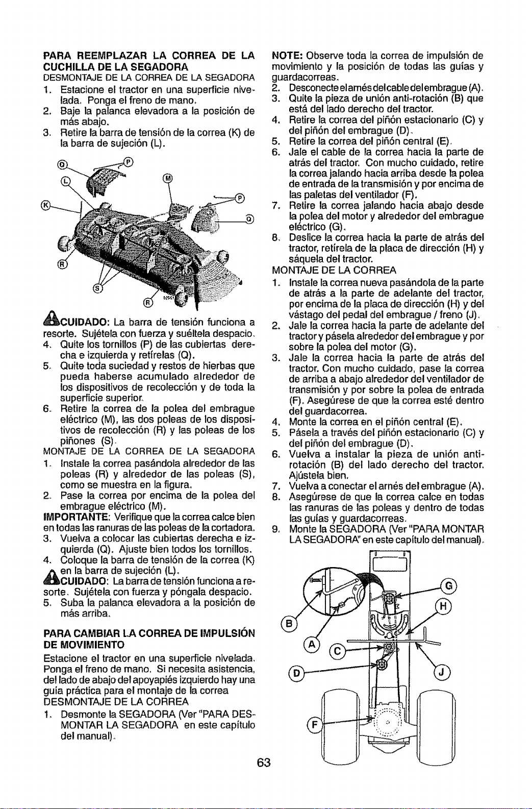
PARA REEMPLAZAR LA CORREA DE LA
CUCHILLA DE LA SEGADORA
DESMONTAJEDE LA CORREADE LA SEGADORA
1. Estacione el tractor en una superficie nive-
ladao Ponga el freno de manor
2. Baje la palanca elevadora a la posici6n de
m#,s abajo.
3. Retire la barra de tensi6n de la correa (K) de
la barra de sujeci6n (L).
_CUIDADO: La barra de tensi6n funciona a
resorte. Suj_tela con fuerza y su_ltela despacio.
4. Quite los tornitlos (P) de las cubiertas dere-
cha e izquierda y ret{relas (Q).
5o Quite toda suciedad y restos de hierbas que
pueda haberse acumulado alrededor de
los dispositivos de recolecci6n y de toda la
superficie superior.
6. Retire la correa de la polea det embrague
el6ctrico (M), las dos poleas de los disposi-
tivos de recolecci6n (R) y las poleas de los
piSones (S)_
MONTAJE DE LA CORREA DE LA SEGADORA
1. Instale ta correa pas&ndola atrededor de las
poleas (R) y alrededor de las poleas (S),
como se muestra en la figura.
2. Pase la correa por encima de ta polea del
embrague elL_ctrico(M).
tMPORTANTE: Verifique que la correa calce bien
en todas las ranuras de las poleas de la cortadora.
3. Vuelva a colocar las cubiertas derecha e iz-
quierda (Q). Ajuste bien todos los tornillos.
4. Coloque ta barra de tensi6n de la correa (K)
en la barra de sujeci6n (L).
CUIDADO: La barra de tensi6n funciona a re-
sorte. Suj_tela con fuerza y p6ngala despacio.
5o Suba la palanca elevadora a la posici6n de
m&s arriba.
PARA CAMBIAR LA CORREA DE IMPULSI6N
DE MOVIMIENTO
Estacione et tractor en una superficie nivelada,
Ponga el freno de mano. Si necesita asistencia,
del lado de abajo det apoyapi_s izquierdo hay una
guia pr_ctica para el montaje de la correa
DESMONTAJE DE LA CORREA
1. Desmonte la SEGADORA (Ver"PARA DES_
MONTAR LA SEGADORA en este capituto
del manual)°
NOTE: Observe toda la correa de impulsi6n de
movimiento y la posici6n de todas las guias y
guardacorreas.
2. Desconecte elam_sdelcable delembrague (A).
3. Quite la pieza de uni6n anti-rotaci6n (B) que
est& del lado derecho del tractor.
4. Retire la correa del pi56n estacionario (C) y
del pi56n del embrague (D).
5. Retire la correa del pifi6n central (E),
6. Jale el cable de ta correa hacia la parle de
atr&s del tractor, Con mucho cuidado, retire
ta correa jalando hacia arriba desde fa potea
de entrada de la transmisi6n y por encima de
las paletas del ventilador (F).
7. Retire la correa jalando hacia abajo desde
la polea del motor y alrededor del embrague
el6ctrico (G)o
8. Desfice la correa hacia la parte de atr&s del
tractor, retirela de la ptaca de direcci6n (H) y
s&quela del tractor.
MONTAJE DE LA CORREA
1o Instale la correa nueva pas&ndola de la parte
de atr&s a la parte de adetante dei tractor,
por encima de la placa de direcci6n (H) y del
v&stago del pedal del embrague / freno (J)_
2. Jale la correa hacia la parte de adelante del
tractor y p&sela alrededor del embrague y por
sobre la polea del motor (G).
3. Jale la correa hacia la parte de atr&s del
tractor. Con mucho cutdado, pase la correa
de arriba a abajo alrededor del ventilador de
transmisi6n y por sobre la polea de entrada
(F)oAsegQrese de que ta correa est_ dentro
det guardacorrea.
4. Monte la correa en el pi56n central (E).
5. P&sefa a trav_s del pi_,6n estacionario (C) y
det pi56n del embrague (D),
6. Vuelva a instalar la pieza de uni6n anti-
rotaci6n (B) del lado derecho del tractor,
Aj_stela bien.
7. Vuetva a conectar el arn6s del embrague (A).
8. Asegt_rese de que ia correa calce en todas
las ranuras de las poleas y dentro de todas
las guias y guardacorreaso
9, Monte la SEGADORA (Ver"PARA MONTAR
LA SEGADORP_'en este capitulo del manual)_
63
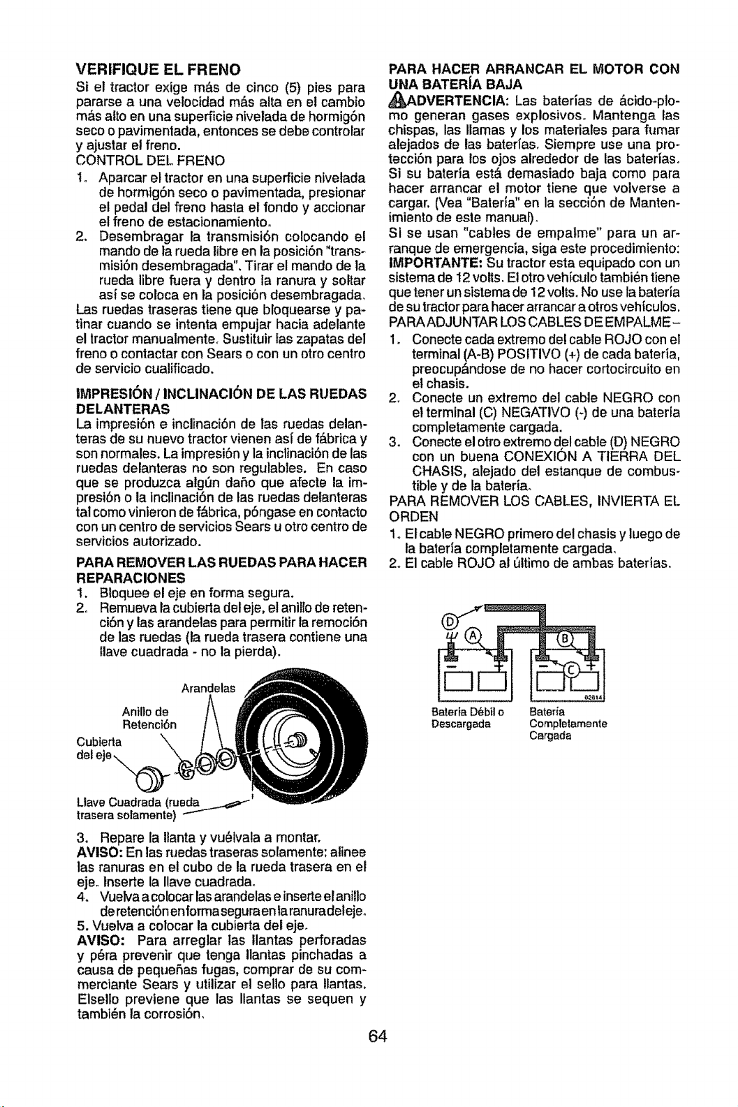
VERIFIQUE EL FRENO
Si el tractor exige m_s de cinco (5) pies para
pararse a una velocidad m&s alta en el cambio
m_s alto en una superficie nivelada de hormigSn
seco o pavimentada, entonces se debe controlar
y ajustar el freno.
CONTROL DEL FRENO
1. Aparcar el tractor en una superficie nivetacla
de hormig6n seco o pavimentada, presionar
el pedal del freno hasta et rondo y accionar
el freno de estacionamiento°
2. Desembragar la transmisi6n colocando e!
mando de ta rueda fibre en la posici6n "trans-
misi6n desembragada'L Tirar el mando de la
rueda libre fiJera y dentro la ranura y soltar
asl se coloca en la posici6n desembragada,
Las ruedas traseras tiene que bloquearse y pa-
tinar cuando se intenta empujar hacia adelante
el tractor manualmente. Sustituir las zapatas del
freno o contactar con Sears o con un otro centro
de servicio cualificado.
IMPRESlON / INCLINACI6N DE LAS RUEDAS
DELANTERAS
La impresi6n e inclinaci6n de las ruedas delan-
teras de su nuevo tractor vienen asi de f&brica y
son normales. La impresi6n y la inclinaci6n de las
ruedas delanteras no son regulabtes. En caso
que se produzca algQn dafio que afecte ta im-
presi6n o la inclinaci6n de las ruedas delanteras
tal como vinieron de f&brica, pSngase en contacto
con un centro de servicios Sears u otro centro de
servicios autorizado.
PARA REMOVER LAS RUEDAS PARA HACER
REPARACIONES
1. Blcquee el eje en forma segura.
2. Remueva la cubierta del eje, el anillo de reten-
ci6n y las arandelas para permitir ia remoci6n
de las ruedas (la rueda trasera contiene una
gave cuadrada - no la pierda).
Arandelas
Anillo de
Retenci6n
Cubierta
deteje._
i
LtaveCuadrada (ruedaj_=_ _"
traserasolamente)
3. Repare ta Ilanta y vu_lvala a montar.
AVISO: En las ruedas traseras solamente: alinee
las ranuras en el cubo de la rueda trasera en el
eje. tnserte la Ilave cuadrada.
4. Vuelva acolocar las arandelas e inserte el anillo
deretenci6nenformaseguraen laranuradeleje_
5. Vuelva a colocar la cubierta del eje.
AVISO: Para arregtar tas Itantas perforadas
y p_ra prevenir que tenga Ilantas pinchadas a
causa de pequeflas fugas, comprar de su com-
merciante Sears y utilizar el sello para llantas.
Elsello previene que las Ilantas se sequen y
tambi_n la corrosi6n,
64
PARA HACER ARRANCAR EL MOTOR CON
UNA BATER[A BAJA
_8,DVERTENCIA: Las baterias de &cido-plo-
mo generan gases explosivos,, Mantenga las
chispas, las llamas y los materiales para fumar
alejados de las baterias. Siempre use una pro-
tecci6n para los ojos alrededor de las baterlaso
Si su bateria est& demasiado baja como para
hacer arrancar el motor tiene que volverse a
cargar, (Vea "Bateria" en la secci6n de Manten-
imiento de este manual).
Si se usan "cables de empalme" para un ar-
ranque de emergencia, siga este procedimiento:
IMPORTANTE: Su tractor esta equipado con un
sistema de 12 volts. El otrovehfculo tambi_n tiene
que tener un sistema de 12volts. No use la bateria
de su tractorpara hacerarrancara otrosvehiculos.
PARAADJUNTAR LOS CABLES DE EMPALME-
1. Conecte cada extremo de! cable ROJO con el
terminal (A-B) POStTIVO (+) de cada bateria,
preocup&ndose de no hacer cortocircuitoen
el chasis.
2. Conecte un extremo del cable NEGRO con
el terminal (C) NEGATIVO (-) de una bateria
completamente cargada.
3. Conecte el otto extremo del cable (D) NEGRO
con un buena CONEXION A TIERRA DEL
CHASIS, alejado det estanque de combus-
tible y de la bateria.
PARA REMOVER LOS CABLES, INVIERTA EL
ORDEN
1_El cable NEGRO primero del chasls y luego de
ta bateria completamente cargada.
2o El cable ROJO al _ltimo de ambas baterias,,
m
r--]
8aterfa D_bil o Batefia
Descargada Completamente
Cargada
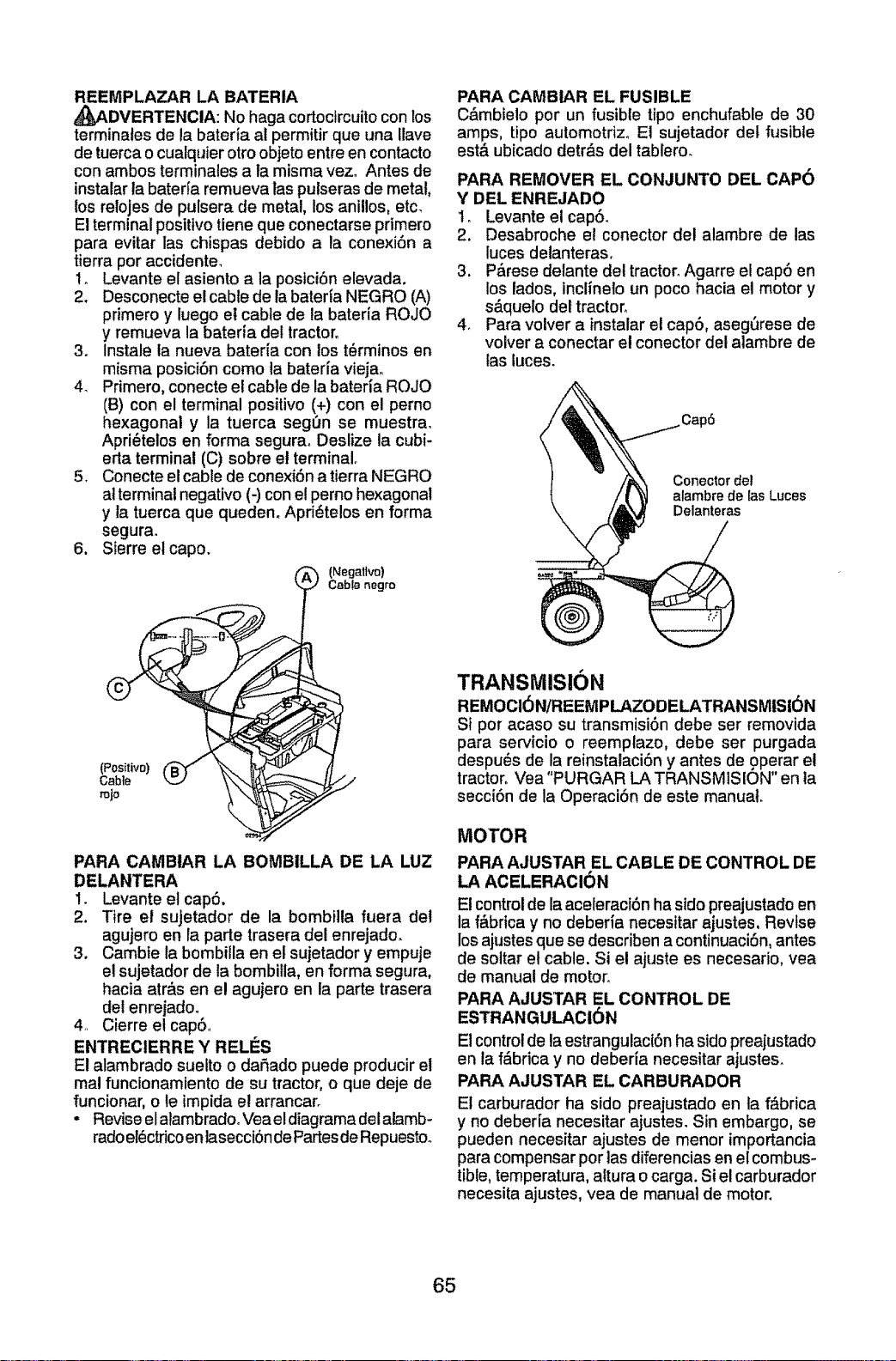
REEMPLAZAR LA BATERIA
_p_DVERTENCIA: No haga cortocircuitocon los
terminales de la bateria al permitir que una Uave
de tuerca o cualquier otroobjeto entre en contacto
con ambos terminales a la misma vez_ Antes de
instalar ta bateffa remueva las pulseras de metal,
los relojes de pulsera de metal, los anillos, etc_
El terminal positivo tiene que conectarse primero
para evitar las chispas debido a la conexi6n a
tierra por accidente_
t. Levante el asiento a la posici6n elevada.
2. Desconecte el cable de la baterfa NEGRO (A)
primero y luego el cable de la bateria ROJO
y remueva la bateria det tractor°
3. Instale ta nueva bateria con los t6rminos en
misma posici6n como la baterfa viejao
4. Primero, conecte e! cable de la bateria ROJO
(B) con el terminal positivo (+) con el perno
hexagonal y la tuerca segOn se muestra.
Apri_telos en forma segura_ Deslize la cubi-
erla terminal (C) sobre et terminal.
5. Conecte e! cable de conexi6n a tierra NEGRO
at terminal negativo (-) con el perno hexagonal
y la tuerca que queden. Apri_telos en forma
segura.
6. Sierre el capo.
(Negative)
CabfB negro
(Positivo)
Gab{e
rojo
PARA CAMBtAR LA BOMBILLA DE LA LUZ
DELANTERA
1. Levante el cap6.
2, Tire el sujetador de la bombilla fuera de!
agujero en la parte trasera de! enrejado.
3. Cambie la bombilla en el sujetador y empuje
el sujetador de la bombilla, en forma segura,
hacia atr_s en el agujero en la parte trasera
del enrejado.
4.. Cierre el cap&.
ENTRECIERRE Y RELI_S
El alambrado suelto o da_ado puede producir et
real funcionamiento de su tractor, o que deje de
funcionar, o le impida el arrancar.
• Revise elalambradooVea eldiagrama delalamb-
radoel_ctricoenlasecci6ndeFartesdeRepuestoo
PARA CAMBIAR EL FUSIBLE
C&mbielo por un fusible tipo enchufable de 30
amps, tipo automotriz, El sujetador del fusible
est& ubicado detr&s del tablero_
PARA REMOVER EL CONJUNTO DEL CAP6
Y DEL ENREJADO
1. Levante etcap6.
2. Desabroche el conector det alambre de las
luces delanteras.
3. P&rese delante det tractor_Agarre el cap6 en
los lados, inclinelo un poco hacia el motor y
s&quelo del tractor.
4. Para volver a instalar el cap6, aseg6rese de
volver a conectar el conector del alambre de
las luces.
Conector del
alambre de EasLuces
Delanteras
TRANSMISION
REMOCI6N/'REEMPLAZODELATRANSMISI6N
Si por acaso su transmisi6n debe ser removida
para secvicio o reemptazo, debe ser purgada
despu_s de la reinstalaci6n y antes de operar el
tractor_Vea "PURGAR LATRANSMISION" en la
secci6n de la Operaci6n de este manual.
MOTOR
PARA AJUSTAR EL CABLE DE CONTROL DE
LA ACELERACION
El controlde la aceleraci6n ha stdopreajustadoen
la f&brica y no deberia necesitar ajustes, Revise
losajustesque se describen a continuaci6n,antes
de soltar et cable. Si e! ajuste es necesario, vea
de manual de motor.
PARA AJUSTAR EL CONTROL DE
ESTRANGULACI6N
El control de la estrangulaci6nha sido preajustado
en la f_brica y no deberia necesitar ajustes.
PARA AJUSTAR EL CARBURADOR
El carburador ha sido preajustado en fa f_brica
y no deber[a necesitar ajustes. Sin embargo, se
pueden necesitar ajustes de menor importancia
para compensar por las diferenciasen el combus-
tible, temperatura, altura o carga. Si el carburador
necesita ajustes, yea de manual de motor.
65
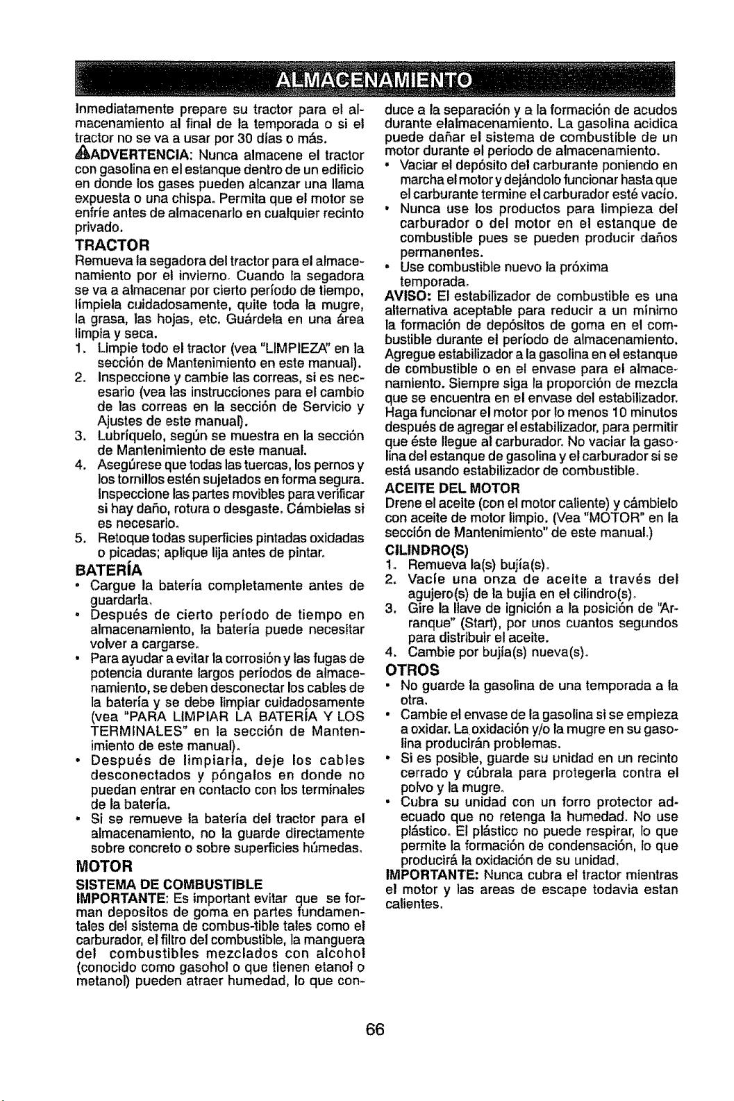
Inmediatamente prepare su tractor para et al-
macenamiento al final de ta temporada o si el
tractor no se va a usar por 30 dias o m&s.
,_kADVERTENCIA: Nunca almacene el tractor
con gasolina en el estanque dentro de un edificio
en donde los gases pueden alcanzar una llama
expuesta o una chispa. Permita que el motor se
enfrte antes de atmacenarto en cualquier recinto
privado.
TRACTOR
Remueva la segadora de! tractor para el almace-
namiento por el invierno_ Cuando la segadora
se va a almacenar pot cierto perfodo de tiempo,
limpiela cuidadosamente, quite toda ta mugre,
la grasa, las hojas, etc_ Gu_rdela en una _rea
limpia y seca.
1. Limpie todo el tractor (vea "LIMPIEZ_' en la
secci6n de Mantenimiento en este manual).
2. Inspeccione y cambie las correas, si es nec-
esario (yea las instrucciones para el cambio
de las correas en la secci6n de Servicio y
Ajustes de este manual).
3. Lubriqueto, seg6n se muestra en la secci6n
de Mantenimiento de este manual.
4. Aseg6rese que todas tastuercas, lospernos y
los tornillos est_n sujetados en forma segura.
inspecctone las partes movibles para verificar
si hay dafio, rotura o desgaste. C_mbielas si
es necesario.
5. Retoque todas superficies pintadas oxidadas
o picadas; aplique lija antes de pintar.
BATERiA
° Cargue ta bateria completamente antes de
guardarla,
• Despu_s de cierto pedodo de tiempo en
almacenamiento, la bateria puede necesltar
volver a cargarse.
• Para ayudar a evitar la corrosi6n y las fugas de
potencia durante largos periodos de almace-
namiento, se deben desconectar los cables de
la bateria y se debe timpiar cuidadosamente
(vea "PARA LIMPtAR LA BATERiA Y LOS
TERMINALES" en la secci6n de Manten-
imiento de este manual).
• Despu_s de limpiarla, deje los cables
desconectados y p6ngalos en donde no
puedan entrar en contacto con los terminales
de la bateria.
, Si se remueve la bateria dei tractor para el
almacenamiento, no la guarde directamente
sobre concreto o sobre superficies ht'Jmedas,
MOTOR
SISTEMA DE COMBUSTIBLE
IMPORTANTE: Es important evitar que se for-
man depositos de goma en partes fundamem
tales det sistema de combus-tible tales como el
carburador, el filtro del combustible, la manguera
det combustibles mezclados con alcohol
(conocido como gasohol o que tienen etano! o
metanot) pueden atraer humedad, Io que con-
duce a la separaci6n y a la formaci6n de acudos
durante elatmacenamiento. La gasolina acidica
puede da6ar el sistema de combustible de un
motor durante el periodo de almacenamiento.
• Vaciar el dep6sito del carburante poniendo en
marcha et motor y dej_,ndolofuncionar hasta que
el carburante termine el carburador estL=vacio.
• Nunca use los productos para limpieza del
carburador o del motor en el estanque de
combustible pues se pueden producir da6os
permanentes.
, Use combustible nuevo la pr6xima
temporada.
AVISO: Et estabilizador de combustible es una
alternativa aceptable para reducir a un mfnimo
la formaci6n de dep6sitos de goma en el com-
bustible durante el perfodo de almacenamiento.
Agregue estabilizador a la gasolina en el estanque
de combustible o en el envase para et almace-
namlento. Siempre siga la proporci6n de mezcla
que se encuentra en el envase del estabilizador.
Haga funcionar el motor por lo menos 10 minutos
despu_s de agregar et estabilizador, para permitir
que 6ste Ilegue al carburador, No vaciar la gaso-
lina del estanque de gasolina y el carburador si se
est& usando estabilizador de combustible.
ACEITE DEL MOTOR
Drene el aceite (con et motor caliente) y c_mbielo
con aceite de motor limpio. (Vea "MOTOR" en la
secci6n de Mantenimiento" de este manuaL)
ClLINDRO(S)
1. Remueva la(s) bujia(s)°
2. Vacie una onza de aceite a trav6s del
agujero(s) de la bujia en el citindro(s)o
3. Gire la Ilave de ignici6n a la posici6n de '_,r-
ranque" (Start), por unos cuantos segundos
para distribuir el aceite.
4. Gamble por bujia(s) nueva(s)o
OTROS
• No guarde ta gasolina de una temporada a la
otra_
• Cambie el envase de la gasolina si se empieza
a oxidar. Laoxidaci6n y/o la mugre en su gaso-
tina producir&n problemas.
, Si es posible, guarde su unidad en un recinto
cerrado y c_brala para protegerla contra el
polvo y ta mugre.
, Cubra su unidad con un forro protector ad-
ecuado que no retenga la humedad. No use
pl_sticoo E! pl&stico no puede respirar, Io que
permite la formaci6n de condensaci6n, Io que
producir& la oxidaci6n de su unidad.
IMPORTANTE: Nunca cubra el tractor mientras
el motor y las areas de escape todavia estan
calientes.
66
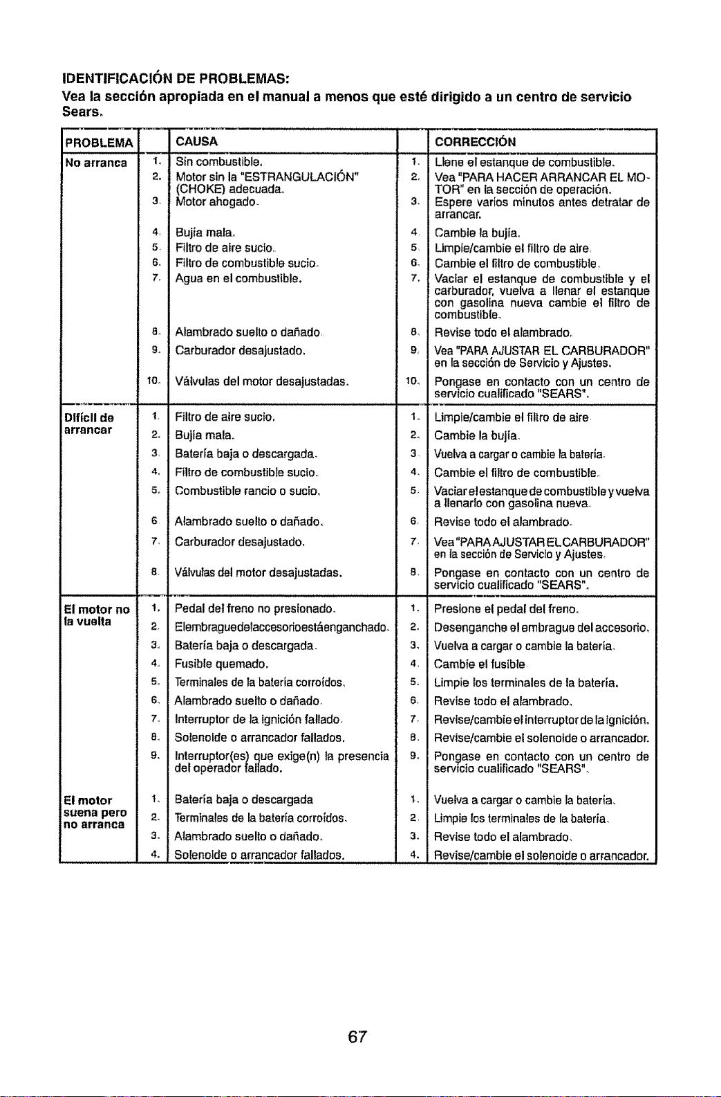
IDENTIFICACION DE PROBLEMAS:
Vea la seccibn apropiada en el manual a menos que
Sears°
PROBLEMA
No arranca
Dlficll de
arrancar
El motor no
la vuelta
El motor
suena pore
no arranca
m
1.
2.
3_,
4_
5,
6,
7o
8.,
9.
10_
2_
4_
5_
6.
74
8,
!.
2,
5o
6_
7°
8°
"L
2.
3.
4.
CAUSA
Sin combustible.
Motor sin la "ESTRANGULACtON"
(CHOKE) adecuadao
Motor ahogado.
Bujia mala.
Filtro de aire sucto,
Filtro de combustiblesucio.
Ague en el combustible.
Alambrado suelto o daf}ado
Carburador desajustadoo
Vblvulas del motor desajustadas,
Filtro de aire sucio.
Bujia mala,,
Baterfa baja o descargada,
Flllro de combustible sucioo
Combustible rancio o sucio,
Alambrado suelto o da_ado,
Cerburador desajustado,
V&lvulasdel motor desajustadas.
Pedal det freno no presionado.
Elembraguedelaccesofloest&enganchado.
Bateria baja o descargada,
Fusible quemado.
Terminales de la bateria corroidos_
Alambrado suetto o daSado,
interrupter de la lgnici6n fatlado_
Solenofde o arrancador fallados.
Interruptor(es) que exige(n) la presencia
det operador lallado.
Bateria baja o descargada
Terminales de la bateria corroidos,
Alambrado suelto o dafiado°
Solenoids o arrancador fallados.
est_
2_
3°
4,
8,
6_
7,
8,,
10_
1,,
2.,
3,
4.
5_
6,
7_
81
2°
3.
4_
5°
6,
7.
8_
9o
2,
3°
4.
dirigido a un centre de servicio
CORRECCION
Llene el estanque de combustible.
Vea "PARA HACER ARRANCAR EL MO-
TOR" en la secci6n de operaci6no
Espere varies minutes antes detratar de
arrancar.
Cambie la buj{ao
Umpie/cambie el filtro de aire,
Cambie el fiftro de combustibte_
Vaclar el estanque de combustible y el
carburador, wJelva a Ilenar el estanque
con gasoltna nueva cambie et filtro de
combustible,.
Revise todo et alambradoo
Vea "PARAAJUSTAR EL CARBURADOR"
en la secci6n de Ssrvicioy Ajusteso
Pongase en contacto con un centre de
servicio cualificado "SEARS",
Umpte/cambie et filtro de aire
Cambie la bujiao
Vuelva a cargaro carnbieta baterla_
Cambie et filtro de combustible_
Vaciar elestanque de combustible yvuetva
a tlenarlo con gasoline nueva.
Revise todo et alambradoo
Vea"PARAAJUSTAR EL CARBURADOR"
en la secci6nde Servicloy Ajustes_
Pongase en contac,!o con un centre de
servicio cualificado SEARS o
Presione el pedal del freno,
Desenganche el embrague del accesorio,
Vuelva a cargar o cambie la baterta.
Cambfe e! fus{ble.
Limpie _osterminales de la bateria,
Revise todo el alambradm
Revtse/cambie el interrupterde fa tgnici6n,
Revise/cambie el solenolde o arrancador.
Pongase en contacto con un centre de
servicio cualificado "SEARS".
Vuelva a cargar o cambie la bateria,
Umpie los terminalesde la baterfa,
Revise rode el alambrado,
Revise/cambie el solenoide o arrancador.
67
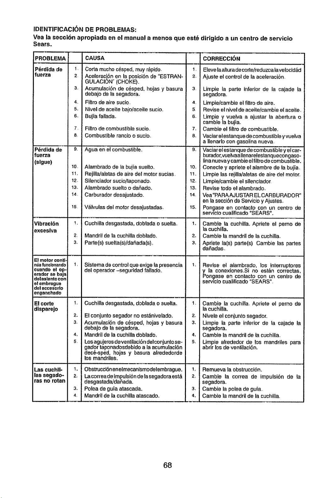
IDENTIFICACION DE PROBLEMAS:
Vea la secci6n apropiada en el manual a menos que est6 dirigido a un centro de servicio
Sears.
!PROBLEMA
P_rdida de I
fuerza 2
P_rdida de
fuerza
(slgue)
Vibraci6n
exceslva
El molor contl.
nt_afundon_ndo
cuando el op-
erador se baja
de|asiento con
el embrague
de| accesorlo
enganchsdo
El corte
disparejo
Las cuchll-
las segado.
ras no rotan
4_,
5o
6_
8-
9,
10
11,
12,
13,
14,
15
2,
3_
CAUSA
Corta mucho c6sped, muy r_pido,
Aceleract6n en la posiciSnde "ESTR
GULACION _ (CHOKE).
Acumufaci6n de c_sped, hojas y ba.,
debajo de la segadora,
Fit|re de airs sucio.
Nivet de aceite bajo/aceite sucioo
Bujla falladao
Filtro de combustible sucioo
Combustible rancio o suctoo
Agua en el combustible
Atambrado de la bujia suelto,
Rejilla/aletas de aire del motor sucias
Silenciador sucio/taponadoo
Alambrado suelto o da_ado,
Carburador desajustado.
V&lvufas del motor desaJustadaso
Cuchitla desgastada, doblada o suelt,*
Mandril de la cuchilla doblado.
Parle(s) suelta(s)/dafiada(s),
1 Sislema de controlque exige la preset
del operador -seguridad fallado,
,,,,,,,,,,,,,,, ,,,,,,,,,,,,,,,,,,, , ,,, ,,, ,L, , ,,
I Cuchilla desgastada, doblada o sueltz
2_ El conjunto segador no est&niveladoo
3. AcumulaciSn de c_sped, hojas y bas
debajo de la segadora.
4. Mandril de la cuchilla doblado°
5 Los agujeros de ventllact6n delconjunto
gador taponadosdebido a la acumulac
deck-sped, hojas y basura alrededo
los mandriles,
Obs_]'ucclSnenelmecantsmodelembrague,
La correa de imputsi6nde la segadoraest&
dssgastadaJdaSadao
Potea de guia atascada.
Mandril de la cuchllla atascado.
t,
3.
4r
5
6o
7_
8,,
9_
10o
1%
12o
13.
14
!5o
2_
3o
1,,
2_
3o
4o
2,!
3. i
4,1
CORRECCI(_N
Eleve laalturade corle/reduzcalavelocid&d
Ajuste el control de la aceleraci6n
Limpie la parts inferior de la cajade ta
segadora,
Limpie/cambie el ditto de aireo
Revise el nivel de aceite/cambie el aceite.
Limpie y vuelva a ajustar la abertura o
cambie la bujiao
Cambie el fit|to de combustible.
Vaciarel estanque de combustible y vuelva
a Ilenarto con gasolina nueva
Vaciar el estanque de combustible y el car-
burador,vuelvaallenarelestanquecongaso.
lina nueva y cambieel fiftro de combustible.
Conecte y apdete el alambre de la bujia,
Limpie tas rejilla/aletas de sire del motor,
Limpie/cambie el silenciador
Revise todo el alambradm
Vea"PARAAJUSTAR ELCARBURADOR"
en la secci6n de Servtcio y Ajustes_
Pongase en contaclo con un centre de
servtctocualificado "SEARS".
Cambie la cuchillaoApdete el perno de
la cuchilfa.
Camble la mandril de ta cuchiltao
Aprtete tats) parts(s) Cambie las parles
daSadas.
Revise et atambrado, los interruptores
y la conexiones.Si no est_n correctas,
Pon_ase en contacto con un centre de
serv_mo cualificado "SEARS"
Cambie la cuchilla. Apriete el pemo de
la cuchilta,
Nlvele el conJuntosegadoro
Limpie la parte inferior de la cajade la
segadora,
Cambie la mandril de ta cuchilla,
Limpie alrededor de los mandrlles pars
abrir los de venlilaci6n,
Remueva la obstrucci6n.
Cambie la correa de impulsi6n de la
segadora°
Cambie la poles de gula.
Cambte la mandril de la cuchilla,
68
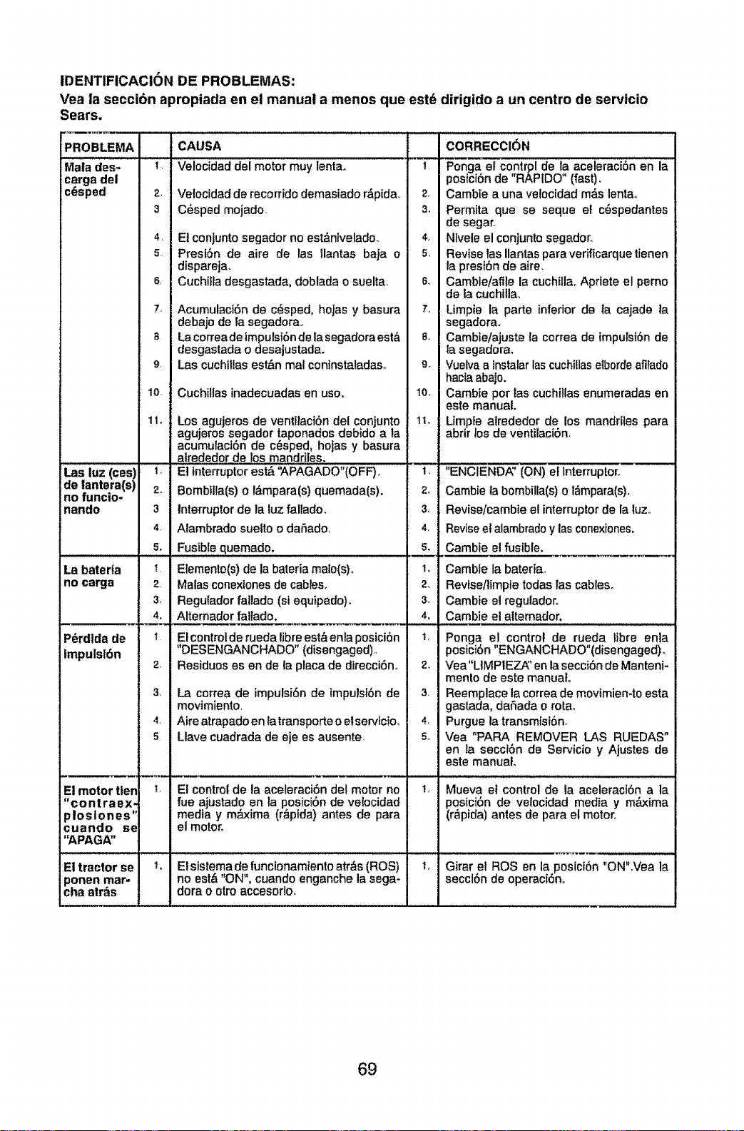
IDENTIFICACION DE PROBLEMAS:
Vea la seccibn apropiada en el manual a manes qua est_ dirigido a un centre de servicio
Sears.
PROBLEMA CAUSA CORRECCION
Mala des_ ! Velocidad del motor muy lenta° --1 Ponga st contrpl de la aceleracion en la
carga del posictOnde "RAPIDO" (fast).
c_sped 2, Vetocidad de recorrido demasiado r_pida_ 2. Camb[e a una veloctdad m_s lenta,
3 C_sped mojado 3, Permtta que se seque el cOspedantes
de segaro
4 El conjunto segador no est&nivelade_ 4. Nivele el conjuntosegador.
5 PresiOn de aire de las llantas baja 0 s. Reviselasllantasparaverfficarquetienen
dtspareja, la preston de aire_
s Cuchilla desgastada, doblada o suelta s Camble/afile la cuchillaoApriete el pemo
de la cuchilla_
7. AcumulactOn de c_sped, hojas y basura 7 Limpie la parte inferior de la cajade la
debajo de la segadera, segadora.
8 Lacorreadeimpulst6ndelasegadoraest_, 8o Cambie/ajuste fa correa de impulsion de
desgastada o desajustada, la segadorao
9 Las cuchillas est&n mal coninstaladaso 9_ Vuelva a Instalarlas cuchiIlasetborde afi_ado
hacla abajo.
lo Cuchilias inadecuadas en use. lo. Cambie per tas cuchillas enumeradas en
este manual.
11. Los agujeros de ventilacibn del conjunto 11. Limpte alrededor de los mandrites para
agujeros segador taponados debido a la abrir los de ventilaciOn.
acumulactOn de c_sped, holas y basura
alrededor de los mandriles.
Las luz (ces) 1. El interrupterest_ '_APAGADO"(OFF). 1_ "ENCIEND/_' (ON) el interrupter.
de lantera(s) 2_ Bombtlla(s) o l_mpara(s) quemada(s). 2. Cambie ta bombilla(s) o l&mpara(s).
no funcio-
nando 3 Interrupter de la luz fallado_ 3, Revise/cambie el interrupterde la luz_
4 Alambrado suetto o da_ado 4 Reviseel alambradoy las cenexiones,
s. Fusible quemado, 5. Cambie el fusible.
La baterta I Elemento(s)de la bateria malo(s)o 1, Camble la bateriao
no carga 2 Malas conexionesde cables. 2 Revfse/limpie todas las cables°
3_ Regulador faltado (si equipado). 3- Cambie el regulador.
4. Alternador fallado, 4, Cambie e! altemador,
P_rdlda de
ImpulsiOn
Elcontrolderuedatibreest&entapesiciOn I Penga el control de rueda libre enla
"DESENGANCHADO" (disengaged) _ posiciOn "ENGANCHADO"(disengaged)_
2 Residues es en de la placa de direcciOno 2_ Vea"LtMPIEZ_' en la secciOn de Manteni-
mento de este manual.
3. La correa de impulsi6n de impulsion de 3 Reemplace la correa de movimiemto esta
movimiento gastada, dafiada e rotao
4 Aire atrapado en ta transporteo etservtcio_ 4 Purgue la transmisiOn.
5 Llave cuadrada de eje es ausente 5 Vea "PAPA REMOVER LAS RUEDAS"
en la sscciOn de Servicio y Ajustes de
este manual.
El motor tlen _ El controlde la aceleraciOn det motor no 1_ Mueva et control de la aceleraciOn a ta
"contraex- rue ajustado en la posiciOnde velocidad posiciOn de velocidad media y m_xima
ploslones" media y m_ima (r_ptda) antes de para (r_pida) antes de para el motor°
cuando se el moto[_
"APAGA"
El tractor se _, El sfstemade functonamtento atr&s (ROS) 1
ponen mar- no est& "ON", cuando enganche la sega-
cha atr_s dora o otro accesorio,
Girar et ROS en la posici6n "ON".Vea la
secct6n de operacfOno
69

70
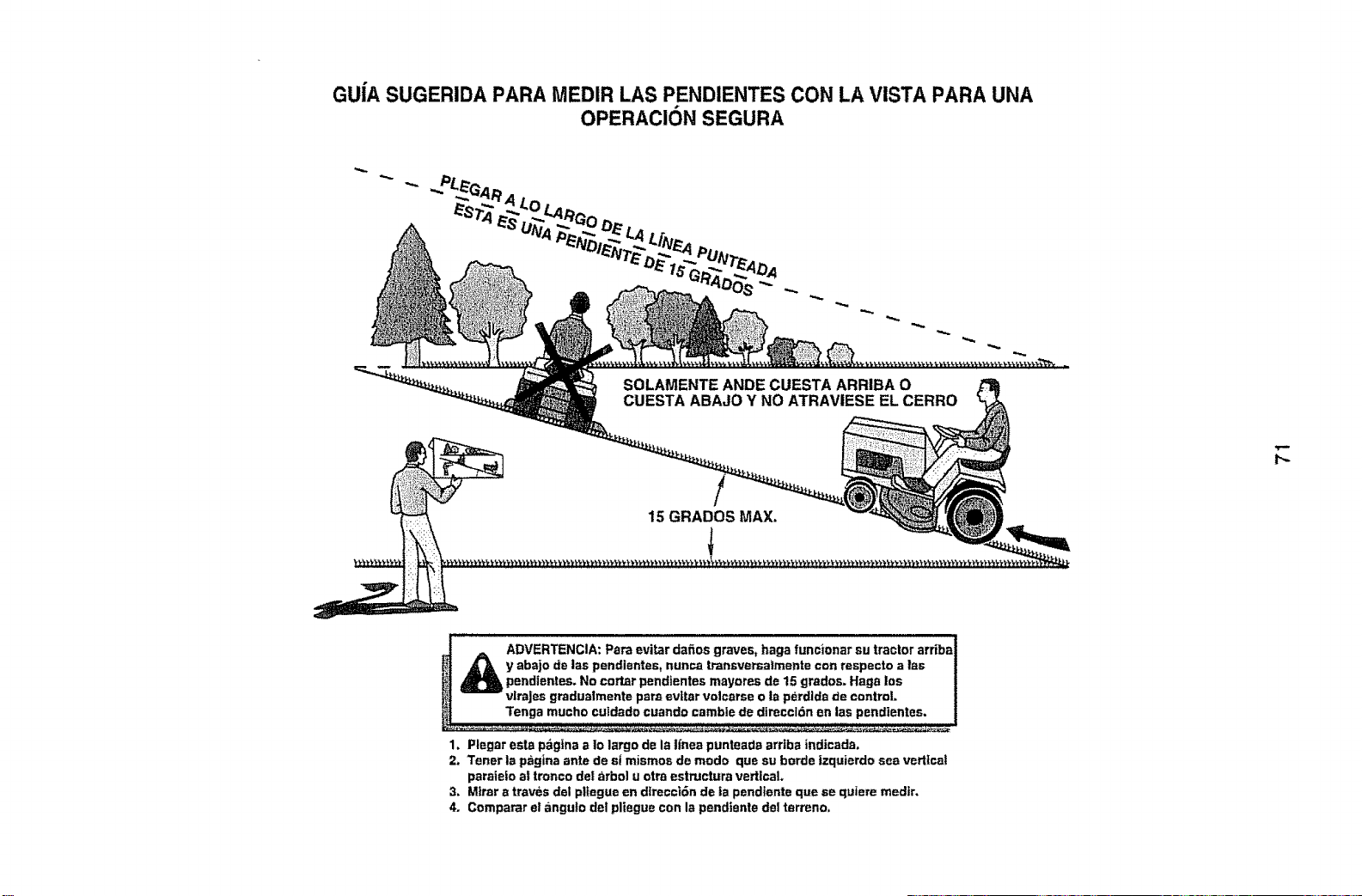
GUiA SUGERIDA PARA MEDIR LAS PENDIENTES CON LA VISTA PARA UNA
OPERACION SEGURA
SOLAMENTE ANDE CUESTA ARRIBA O
CUESTA ABAJO Y NO ATRAVIESE EL CERRO
!
15 GRADOS MAX.
t_
!" A' ADVERTENCIA: Pare evitar dafios graves, haga funcionar su tractor ardba
ill
_]_ y abajo de las pendientes, nunca transversaimente con respecto alas
pendientes. No cotter pendientes mayores de 15 grados. Haga los
vlrajes gradualmente pare ev|tar volcarse o ta perdlda de control.
Tenga mucho culdado cuando camble de direccldn en las pendientes.
1. Piegar eata pbgfna a Io largo de la Ifnea punteade arr|ba indicada.
2. Tenet la peg|ha ante de st mismos de modo que su horde |zquierdo sea vertical
peraiefo a! tronco de! _rbol u otra estructura vertical.
3. Miter a traves del pl_egueen dlreeci6n de |a pendlente que se quiere medir.
4. Comparar el angulo de! pliegue con la pendtente de! terreno.

You'll f_nd the auswer and more on managemyheme.com - for free!
• Find this and atl your other product manuaL_online,
• Get answers from our team of home e×pert_,
• Get a personalized maintenance p|an for your home.
• i.formotionandtoo tohotp ,thhomep,oj ,t,.
manage home ,,:_'_
, b...,.,,o,o,,b_o°,, if=:
;::.7 _:
r:iiii: ?;
:5::
!!c -: £?:
i.i:_,i)
):?_:i!:i;):
Your Home
For repair- in your home - of all major brand appliances,
lawn and garden equipment, or heatingand cooling systems, i_i;!::i_i_.:_:._
no matter who made it, no matter who sold it! _:_:_
For the replacement parts, accessoriesand .............
owner's manuals that you need to do-it-yourselfo ;::___:_
For Sears professional installation of home appliances
and items like garage door openers and water heaters.
1-800-4-MY-HOME ® Anytime, day or nlghl
(!-800.-469-4663) (UoS.A_and Canada)
wwwosears.com www.sears .ca ili_i::_!
i !!;:::!:!
Our Home
For repair of carry_in products like vacuums, lawn equipment,
and electr6nics, call or go on-line for the nearest
Sears Parts and Repair Center.
1-800488-1222 Anytime, day or night (U,S,.A on_y)
www,sears.com
To purchase a protection agreement (U,,SA_)
or maintenance agreement (Canada) on a product sewiced by Sears:
1-800-361-6665 (Canada)1-800-627-6655 (USA)
Parepedirserviciode reparad6n
a domicilio,y paraordenarplazas:
1.SBB.SLI-HOGAR®
Au Canada pourserviceen frang_is:
1.800-LE-FOYERMc %:;i
(1-800-633,6937)
www,sears ,ca
©_ Brands,LLC
® Registered Trademark I m Trademark t s_ Service Mark e! Seers Brands, LLC
TM 8M
® Marca Reglstrade I Ma_ce de F_bdca t Merca de Ser_iclode Sears Brands, LLC
Marque de commerce / M_rque d_pos_e de Seers Brands, LLC
06.2! .10 JA Printed in the U.S.A.


