EN
PKG3UMIMEN-101
www.bora.com
Operating and installation instructions PKG3
BORA Pro gas cooktop
1.
2.
2.
1044124 - 44

EN
2
www.bora.com
5.5.2 Surface mounting ........................................................... 20
5.6 Installing the control knob in the floor unit front panel .
20
5.6.1 Cooktop bore holes ........................................................ 20
5.6.2 Example bore holes ........................................................ 21
5.6.3 Fitting the control knob .................................................. 21
5.7 Gas installation .............................................................. 22
5.7.1 Gas connection .............................................................. 22
5.7.2 Connecting the gas supply ............................................. 22
5.7.3 Additional installation notes for Australia and New
Zealand (AU/NZ) ............................................................ 22
5.7.4 Changing the gas type ................................................... 23
– Changing the gas burner nozzle in the gas burner ........23
5.8 Installing the cooktops .................................................25
5.8.1 Installing the cooktop ..................................................... 25
– Inserting the cooktop (ports on the front) .....................25
– Levelling the cooktop (if necessary) ..............................25
– Securing the cooktop ...................................................26
5.8.2 Installation rotated by 180° (alternative installation
variation) ........................................................................ 26
5.9 Establishing communication and power connection ..26
5.9.1 Connecting the control knobs ........................................ 26
– Connecting the control knobs to the cooktop .........26
5.9.2 Establishing contact between the cooktop extractor and
cooktops ......................................................................... 27
5.9.3 Connecting the power supply ........................................ 27
– Connecting the cooktop to the power supply................28
5.10 Basic configuration ......................................................28
5.10.1 Gas configuration ........................................................... 28
5.11 Initial operation .............................................................28
5.11.1 Using the gas cooktop for the first time ........................ 28
– Using the gas cooktop together with the cooktop
extractor for the first time .............................................28
– Faults during initial operation ........................................29
5.12 Function test .................................................................. 29
5.13 Sealing the appliances .................................................. 29
5.14 Handover to user ........................................................... 29
6 Configuration menu 30
– Menu overview .............................................................30
6.1 How to use the menu .................................................... 30
– Calling up the menu ......................................................30
– Selecting and confirming menu items ...........................30
– Making, confirming and saving settings ........................30
– Closing the menu..........................................................30
6.2 Initial operation .............................................................30
6.2.1 Gas configuration menu items ....................................... 30
– Menu item
CE
: GPU configuration ...............................30
– Menu item
CF
: gas burner characteristic curves .........31
– Menu item
Ch
: GPU reset ...........................................31
7 Functions and operation 32
7.1 Knob operation ..............................................................32
– Operating the knob ring ................................................32
– Operating the touch surface .........................................32
7.2 Switching the system on and off .................................32
– Switching on .................................................................32
– Switching off ................................................................32
1 General information 4
1.1 Liability ............................................................................. 4
1.2 Validity of the operating and installation instructions . 4
1.3 Product conformity ......................................................... 4
1.4 Data protection ................................................................ 4
1.5 Presentation of information............................................ 4
2 Safety 5
2.1 Use as intended ............................................................... 5
2.2 People with limited abilities ........................................... 5
2.3 General safety instructions ............................................ 5
2.4 Safety instructions for installation ................................. 6
2.5 Safety instructions – operation ...................................... 8
2.6 Safety instructions – cleaning and maintenance .......10
2.7 Safety instructions – repairs, servicing and spare parts
10
2.8 Safety instructions – disassembly and disposal ........10
3 Technical data 11
3.1 BORA Pro gas cooktop PKG3........................................11
3.2 BORA Professional 3.0 control knob dimensions ....... 12
4 Appliance description 13
4.1 Control knob ..................................................................13
– How it works .................................................................13
– Structure ......................................................................13
– Operating elements ......................................................13
– Control knob display .....................................................13
– Control knob assignment .............................................. 13
4.2 Cooktop appliance description.....................................14
– Display and symbols .....................................................14
– Layout and size of the cooking zones ...........................14
– Gas cooktop PKG3........................................................14
4.2.1 How gas cooktop PKG3 works ....................................... 14
– Power levels ..................................................................14
– Suitable cookware ........................................................14
4.3 Safety devices ................................................................15
– Safety shut-down ..........................................................15
– Residual heat indicator .................................................15
– Overheating protection .................................................15
– Childproofing feature ....................................................15
5 Installation 16
5.1 General installation instructions ................................. 16
5.2 Checking the scope of delivery .................................... 16
5.3 Tools and aids ................................................................ 16
5.4 Assembly instructions ...................................................17
5.4.1 Safety clearances ........................................................... 17
5.4.2 Minimum installation dimensions (standard set-up) ...... 17
5.4.3 Worktop and kitchen units ............................................. 17
5.4.4 Special installation instructions for gas cooktop PKG3 . 17
– Positioning of the gas cooktop PKG3 with two cooktop
extractors .....................................................................18
– Air supply for gas cooktop PKG3 ...................................18
5.4.5 Recirculation when using the cooktop extractor as a
recirculation system ....................................................... 18
5.5 Cut-out dimensions .......................................................19
5.5.1 Flush installation ............................................................ 19
Table of Contents

EN
3
www.bora.com
7.3 Operating the cooktops ................................................33
7.3.1 General operating instructions for cooktops ................. 33
7.3.2 Special operating instructions for gas cooktop PKG3 ... 33
– Correct use of the gas hob ...........................................33
– Using the gas cooktop together with the cooktop
extractor .......................................................................34
7.3.3 Setting cooking zone power levels ................................. 34
– Increasing the power level ............................................34
– Reducing the power level ..............................................34
7.3.4 Cooktop power setting ................................................... 34
7.4 Function menu ............................................................... 34
– Calling up the function menu ........................................34
7.4.1 Variable heat retention function ..................................... 35
– Activating the heat retention function ...........................35
– Increasing or reducing the active heat retention level
35
– Deactivating the heat retention function ..................35
7.4.2 Timer function/automatic cut-off .................................. 35
– Activating cooking zone timers .................................35
– Setting the time and starting the timer ....................36
– Changing active timers ..............................................36
– Switching the timer off early .....................................36
– Time lapsed ................................................................. 36
7.4.3 Automatic heat up function ............................................ 36
– Activating the automatic heat up function.....................36
– Deactivating the automatic heat up function early ........37
– Time lapsed ..................................................................37
8 Cleaning and maintenance 38
8.1 Cleaning agents .............................................................38
– Cleaning products for glass ceramic cooktops .............38
8.2 Cleaning the cooktops ..................................................38
8.2.1 Cleaning glass ceramic cooktops .................................. 38
8.2.2 Cleaning the pan supports ............................................. 39
8.2.3 Cleaning the gas burner parts ....................................... 39
8.3 Looking after your cooktops ........................................40
8.4 Cleaning the control knobs ..........................................40
– Cleaning the knob ring..................................................40
– Cleaning the touch surface and the knob housing ........40
9 Troubleshooting 41
10 Decommissioning, disassembly and
disposal 43
10.1 Decommissioning .......................................................... 43
10.2 Disassembly ...................................................................43
10.3 Environmentally-friendly disposal ................................ 43
11 Warranty, technical service, spare
parts, accessories 44
11.1 BORA manufacturer’s warranty....................................44
11.2 Service ............................................................................44
11.3 Spare parts ....................................................................44
11.4 Accessories .................................................................... 44
12 Notes 45

EN
4
General information
www.bora.com
1 General information
1.4 Data protection
During operation your cooktop extractor saves pseudonymised
data such as menu settings entered by you, operating hours
of the individual technical units and the number of functions
selected. Furthermore, your cooktop extractor documents errors
in combination with the number of operating hours.
Data can only be read out manually via your cooktop extractor.
This decision is therefore your responsibility.
These saved data then enable a rapid error search and
troubleshooting in the event of servicing.
1.5 Presentation of information
We use standard formatting, numbering, symbols, safety
instructions, terms and abbreviations so that you can work
quickly and safely when using this manual.
The term “appliance” is used to refer to cooktops, cooktop
extractors or cooktops with integrated cooktop extractor.
Instructions are indicated with an arrow.
X
Always follow all instructions in the prescribed order.
Enumerations are indicated with a bullet point at the start of
the line:
O
Enumeration 1
O
Enumeration 2
i
Information notes point to special features that must be
taken into account.
Safety and warning instructions
The safety and warning instructions in this manual are
emphasised with symbols and signal words.
Safety and warning instructions are structured as follows:
WARNING SYMBOL AND SIGNAL WORD!
Type and source of danger
Results of non-compliance
X
Measures to minimise risk
Please note:
O
warning symbols draw attention to a high risk of injury.
O
The signal word indicates the severity of that risk.
Warning
symbol
Signal word Risk
ü
Danger Indicates an immediate, hazardous
situation which causes death or
serious injury if not respected.
ü
Warning Indicates a potentially hazardous
situation which can cause death or
serious injury if not respected.
Caution Indicates a potentially hazardous
situation which can cause minor
injury or damage to property if not
respected.
Tab. 1.1 Meaning of the warning symbols and signal words
These instructions contain important information to protect you
from injury and prevent damage to the appliance.
Please read these instructions carefully before installing or using
the appliance for the first time.
Other documents apply alongside these instructions.
Please by all means adhere to all documents that form part of
the scope of delivery.
Assembly, installation and commissioning must always occur
in line with national laws, regulations and standards. The work
must be performed by qualified specialists who are familiar with
and comply with the supplementary regulations of the local
utility companies.
All safety and warning information as well as the handling
instructions in the accompanying documents must be observed.
1.1 Liability
BORA Holding GmbH, BORA Vertriebs GmbH & Co KG, BORA
APAC Pty Ltd and BORA Lüftungstechnik GmbH – hereinafter
referred to as BORA – does not assume any liability for damage
arising from disregard for or non-adherence to the documents
included in the scope of delivery!
Furthermore, BORA shall not be held liable for damage caused
by improper installation or failure to observe the safety and
warning instructions!
1.2 Validity of the operating and
installation instructions
These instructions apply to several appliance versions. It is
therefore possible that some of the features described do not
apply to your appliance. The details of the figures contained
herein may differ from some appliance versions and are to be
understood as schematic diagrams.
1.3 Product conformity
Directives
The appliances meet the following EU/EC directives:
2014/30/EU EMC Directive
2014/35/EU Low Voltage Directive
2009/125/EC Ecodesign Directive
2011/65/EU RoHS Directive
Regulations
Gas appliances meet the following EU directives:
(EU) 2016/426 regulation on appliances burning gaseous fuels

EN
5
Safety
www.bora.com
2 Safety
The appliance complies with the stipulated safety
requirements. The user is responsible for the safe
use of the appliance, cleaning and maintenance.
Improper use can lead to personal injury and damage
to property.
2.1 Use as intended
The appliance is solely intended for preparing food in
private households.
This appliance is not intended for:
O
outdoor use
O
heating rooms
O
cooling, ventilating or dehumidifying rooms
O
use in mobile installation sites such as motor
vehicles, ships or aeroplanes
O
use with an external timer or a separate remote
control system (except for emergency shutdown)
O
use at altitudes of over 2,000m (metres above sea
level)
O
use with an extractor hood
Any other use or any use that goes beyond that which
is described here is classed as unintended.
i
BORA does not assume any liability for
damages caused by improper use or incorrect
operation.
All misuse is prohibited!
2.2 People with limited abilities
Children
The appliance can be used by children aged 8 and
over if they are supervised or have been instructed
how to use the appliance safely and understand
the resultant risks. Children must not play with the
appliance.
X
Use the childproofing feature in order to prevent
children from switching on the appliance or
changing the settings when they are unattended.
X
Supervise children in the vicinity of the appliance.
X
Do not store any items that could be of interest to
children in storage spaces above or behind the
appliance. Otherwise, they will be tempted to
climb onto the appliance.
i
Any work involving cleaning and maintenance
must not be carried out by children unless they
are supervised at all times while doing so.
People with reduced physical, sensory or
mental capacities
The appliance can be used by people with reduced
physical, sensory or mental capacities or a lack of
experience and/or knowledge if they are supervised
or have been instructed how to use the appliance
safely and understand the resultant risks.
Operation can be restricted using the childproofing
feature.
DANGER!
Risk of burns from hot cookware and food
Handles projecting over the edge of the worktop
are asking to be grabbed.
X
Keep children away from hot cooking zones or
ensure they are supervised at all times.
X
Do not turn pot and pan handles so they stick
out beyond the worktop.
X
Make sure that hot pots and pans cannot be
pulled down.
X
If necessary, use suitable stove guards or
covers.
X
Only use stove guards and covers that are
approved by the appliance manufacturer;
otherwise, there is a risk of accidents.
X
To choose a suitable stove guard, contact your
specialist supplier or the BORA Service Team.
2.3 General safety instructions
DANGER!
Packaging components are a choking hazard
Packaging components (e.g. lm, polystyrene) can
be life-threatening for children.
X
Store all packaging components out of reach of
children.
X
Dispose of the packaging properly and
immediately.

EN
6
Safety
www.bora.com
CAUTION!
Risk of injury from heavy lifting
If not handled correctly, carrying and installing
appliances can cause injury to the limbs or torso.
X
If necessary, carry and install the appliance with
another person.
X
Use appropriate aids to prevent damage or
injury.
CAUTION!
Damage from improper use
The appliance surfaces must not be used as
work or storage surfaces. This can damage the
appliances (particularly in the case of hard and
sharp objects). Never use the appliances as work
or storage surfaces.
X
Keep hard or sharp objects away from the
appliance surfaces.
Faults and errors
X
In the case of faults and errors, follow the
instructions in the “Troubleshooting” chapter.
X
In the event of any faults or errors that are not
mentioned, switch the appliance off and contact
BORA Service.
Pets
X
Keep pets away from the appliance.
2.4 Safety instructions for
installation
i
Assembly, installation and commissioning of
the appliance must always occur in line with
national laws, regulations and standards.
The work must be performed by qualified
specialists who are familiar with and comply
with the supplementary regulations of the local
utility companies.
i
During installation maintain the minimum
clearance stated in the “Installation” (“Safety
clearances”) chapter.
i
Work on electrical components must only be
conducted by trained electrical personnel.
The electrical safety of the appliance is only
guaranteed if it is connected to a protective
conductor system that has been installed in line with
regulations. Ensure that this basic safety precaution
is met.
The appliance must be suitable for the regional
voltage and frequency.
DANGER!
Risk of electric shock or injury from damaged
surfaces
The underlying electronics can be exposed or
damaged due to ssures, fractures or cracks
in appliance surfaces (e.g. damaged glass),
particularly in the vicinity of the operating unit.
This can cause an electric shock. Furthermore, a
damaged surface can cause injuries.
X
Do not touch the damaged surface.
X
If there are any cracks, fissures or fractures,
switch the appliance off immediately.
X
Safely disconnect the appliance from the mains
using the LS switch, fuses, automatic circuit
breakers or contactor.
X
Contact BORA Service.
WARNING!
Risk of injury from damaged components
Damaged components that cannot be removed
without tools can cause injuries.
X
Try not to repair or replace damaged
components yourself.
X
Contact BORA Service.
WARNING!
Risk of injury or damage due to incorrect
components or unauthorised modifications
Incorrect components can lead to personal
injury or damage to the appliance. Modications,
additions or alterations to the appliance can lead to
safety risks.
X
Only use original components.
X
Do not make any modifications, additions or
alterations to the appliance.
CAUTION!
Appliance components can cause injury if
dropped
Appliance components (e.g. pan supports,
operating controls, covers, grease lters, etc.) can
cause injury if dropped.
X
Place any appliance components that have been
removed in a safe place near the appliances.
X
Ensure that no components removed from the
appliances can fall on the floor.

EN
7
Safety
www.bora.com
X
Check the information on the identification plate
and in the event of deviations, do not connect the
appliance.
X
Conduct all work extremely attentively and
conscientiously.
X
Do not connect the appliance to the mains until
the duct system has been installed or the
recirculation filter has been fitted.
X
Only use the connection cables supplied. Where
necessary these are included in the scope of
delivery.
X
Do not use the appliance until installation is
complete. This is the only way to ensure safe
operation.
DANGER!
Risk of electric shock from damaged appliance
A damaged appliance can cause an electric shock.
X
Check the appliance for visible damage prior to
installation.
X
Do not install or connect any damaged
appliances.
X
Do not operate any damaged appliances.
CAUTION!
Risk of burning from control knobs that are
not positioned optimally.
If the control knobs are not installed in a suitable
place, during operation there is a risk of sustaining
burns from the cooktop surface.
X
Only install the control knobs in a suitable place,
which is practical and safe.
2.4.1 Safety instructions for cooktop
installation
DANGER!
Risk of electric shock from incorrect mains
connection
Connecting the appliance to the mains incorrectly
poses a risk of electric shock.
X
Make sure that the appliance has a fixed
connection to the mains voltage.
X
Make sure that the appliance is connected to a
properly installed protective conductor system.
X
Make sure that technical equipment is provided
to enable all of the appliance’s poles to be
disconnected from the mains with a contact
opening width of at least 3mm (LS switch and
automatic circuit breakers, fuses, contactor).
DANGER!
Risk of electric shock from damaged power
supply cable
If the power supply cable is damaged (e.g. during
installation or by coming into contact with hot
cooking surfaces), this can cause an (lethal)
electric shock.
X
Make sure that the power supply cable does not
become trapped or damaged.
X
Make sure that the power supply cable does not
come into contact with hot cooking surfaces.
Special safety instructions for the installation
of gas cooktops
i
Gas installation, appliance installation and
replacing the gas nozzles, as well as changing
the gas type and pressure, may only be carried
out by reliable trained specialists, who are
familiar with and comply with the standard
national regulations and supplementary
regulations of the local utility companies.
X
Observe the special instructions on changing the
gas type and pressure and the specifications for
changing the gas nozzles in the nozzle table (see
Operating instructions).
BORA gas cooktops must only be used with BORA
cooktop extractors.
DANGER!
Risk of explosion and asphyxiation from gas
Leaking gas can lead to an explosion and result
in severe injuries and property damage, or
asphyxiation.
X
Keep sources of ignition (naked flames, electric
fires) away and do not operate any light
switches, or switches on electrical appliances.
X
Do not remove plugs from sockets (risk of
sparking).
X
Close the gas supply immediately and turn off
the mains supply.
X
Ensure there is a good supply of fresh air (open
doors and windows).
X
Plug any leaks immediately.

EN
8
Safety
www.bora.com
WARNING!
Risk of burns from wrongly placed control
knobs
If control knobs are not tted as in sec5.6.6, they
can become hot. Touching the hot control knobs
can cause burns.
X
Control knobs must be fitted at least 10cm
from the edge of the cooktop.
X
If it is not possible to maintain a distance of at
least 10cm, measures must be put in place to
protect the control knobs from the heat.
2.5 Safety instructions – operation
X
Make sure that the base of the cookware as well
as the appliance surfaces are clean and dry.
X
Always lift (do not drag) cookware to prevent
scratching and abrasion on the appliance surface.
X
Do not use the appliance as a storage surface.
X
Switch off the appliance after use.
WARNING!
Risk of burning from hot appliances
Certain appliances and their exposed parts become
hot during use. They should be left to cool down
completely after switching off. Touching hot
surfaces can cause serious burns.
X
Do not touch hot appliances.
X
Pay attention to the residual heat indicator.
WARNING!
Risk of burns due to power cut
During or after a power cut a cooktop that was
previously in operation may still be hot.
X
Do not touch the appliance while it is still hot.
X
Keep children away from the hot appliance.
DANGER!
Risk of fire from overheated oil or fat
Oil or fat in the pot can quickly heat up and ignite.
X
Never leave the appliance unattended when
cooking with oil or fat
X
Never extinguish oil and fat fires with water.
X
Switch off the appliance.
X
Extinguish the fire using a pan lid or a fire
blanket, for example.
WARNING!
Risk of burning and fire from hot objects
The appliance and its exposed parts are hot
during operation and the cooling phase. Objects
in contact with hot appliance components heat
up very quickly and can cause severe burns (this
particularly applies to metal objects such as knives,
forks, spoons, lids or appliance components) or
catch re.
X
Do not place any items on the appliance.
X
Please use suitable accessories (pot holders,
oven gloves).
2.5.1 Safety instructions – cooktop
operation
DANGER!
Danger of fire caused by leaving the cooktop
unattended
Oil or fat in the pot can quickly heat up and ignite.
X
Never leave oil or fat to heat up unattended.
X
Never extinguish oil and fat fires with water.
X
Switch off the cooktop.
X
Extinguish the fire using a pan lid or a fire
blanket, for example.
DANGER!
Danger of explosion caused by flammable
liquids
Flammable liquids in the vicinity of a cooktop can
explode and cause serious injury.
X
Do not spray aerosols near the appliance when
it is in use.
X
Do not place any flammable liquids in the
vicinity of a cooktop.
WARNING!
Risk of burns from hot liquids boiling over
Unattended pans can boil over allowing hot liquids
to escape.
X
Keep an eye on pans when cooking.
X
Try not to let them boil over.
WARNING!
Risk of burns from hot steam
Liquid between the cooking zone and the pan base
can evaporate and cause burns.
X
Make sure that the cooking zone and the pan
base are always dry.

EN
9
Safety
www.bora.com
CAUTION!
Damage caused by sugary and salty foods
Sugary and salty foods and juices can damage the
hot cooking zone.
X
Make sure sugary and salty foods or juices do
not get onto the cooking zone while it is hot.
X
Remove sugary and salty foods and juices from
the hot cooking zone immediately.
Special safety instructions for the operation of
gas cooktops
i
The gas type and pressure must only be
changed by reliable trained specialists who
are familiar with and comply with the standard
national regulations and supplementary
regulations of the local utility companies.
X
Do not use or store any flammable materials near
the appliance.
X
Do not use the appliance to heat the room.
X
Before connecting the appliance, check that the
appliance settings comply with local connection
requirements (gas type and pressure).
DANGER!
Risk of carbon monoxide poisoning
Extractor hoods and other cooking vapour
extractors can impair the safe operation of
appliances that use gas or other fuels due to the
return ow of combustion gases. These gases can
lead to carbon monoxide poisoning.
X
Ensure that exhaust gases are properly
removed.
X
Ensure sufficient ventilation is provided during
operation.
X
Always have a qualified specialist check the safe
operation of the gas appliance during
commissioning.
DANGER!
Risk of explosion and asphyxiation from gas
Leaking gas can lead to an explosion and severe
injuries, or asphyxiation.
X
If you smell gas while using the appliance,
switch it off immediately.
X
Keep sources of ignition (naked flames, electric
fires) away and do not operate any light
switches, or switches on electrical appliances.
X
Do not remove plugs from sockets (risk of
sparking).
X
Close the gas supply immediately and turn off
the mains supply.
X
Ensure there is a good supply of fresh air (open
doors and windows).
X
Inform customer services or your gas installer
immediately.
DANGER!
Fire risk from naked flame
A naked ame can cause adjacent objects to catch
re.
X
Turn the gas flame down to the lowest level if
you remove pots or pans briefly from the hob.
X
Never leave a naked flame unattended.
X
Extinguish any fire using a lid or a fire blanket,
for example.
X
Close the gas supply and turn off the mains
supply.
WARNING!
Risk of burns from hot cooktop extractor when
using gas cooktops
The cooktop extractor and its exposed parts (in
particular the cover ap, stainless steel grease
lter and grease lter tray) become hot when
an adjacent gas cooktop is in use. The cooktop
extractor must be left to cool down after the gas
cooktop has been switched off. Touching hot
surfaces can cause serious burns.
X
Never touch the cooktop extractor when it is
hot.
X
Keep children away from the cooktop extractor
when it is hot or ensure they are supervised at
all times.

EN
10
Safety
www.bora.com
2.6 Safety instructions – cleaning
and maintenance
The appliance must be cleaned at regular intervals.
Dirt can lead to damage, restriction of functions, or
bothersome odours. In the worst case scenario, this
can become a hazard.
X
Remove dirt immediately.
X
When cleaning, only use non-abrasive detergents
to prevent scratching and abrasion on the surface.
X
When cleaning, ensure that no water penetrates
the appliance. Use only a slightly damp cloth.
Never spray the device with water. Water
penetration can cause damage!
X
Do not use a steam cleaner for cleaning. Steam
can cause a short circuit on live parts and thus
lead to property damage.
X
Please follow all instructions in the “Cleaning and
Maintenance” chapter.
Special safety instructions for cooktop cleaning
and maintenance
X
Whenever possible, clean the cooktops after every
use.
X
Only clean the cooktops when they have cooled
down.
2.7 Safety instructions – repairs,
servicing and spare parts
i
The appliance must only be repaired and
serviced by trained specialists who are familiar
with and comply with the standard national
regulations and supplementary regulations of
the local utility companies.
i
Work on electrical components must only be
conducted by trained electrical personnel.
X
Before any repair work, safely disconnect the
appliance from the mains supply.
WARNING!
Risk of injury or damage from improper repairs
Incorrect components can lead to personal
injury or damage to the appliance. Modications,
additions or alterations to the appliance can lead to
safety risks.
X
Only use original spare parts for repairs.
X
Do not make any modifications, additions or
alterations to the appliance.
i
A damaged power supply cable must be
replaced by a suitable power supply cable. This
may only be done by an authorised member of
the After Sales Service team.
2.8 Safety instructions –
disassembly and disposal
i
The appliance must only be disassembled by
trained specialists who are familiar with and
comply with the standard national regulations
and supplementary regulations of the local
utility companies.
i
Work on electrical components must only be
conducted by trained electrical personnel.
X
Before disassembly, safely disconnect the
appliance from the mains supply.
DANGER!
Risk of electric shock from incorrect
disconnection
Incorrectly disconnecting the appliance from the
mains results in a risk of electric shock.
X
Safely disconnect the appliance from the mains
using LS switches, fuses, automatic circuit
breakers or contactors.
X
Use an authorised measuring device to ensure
that there is no power to the appliance.
X
Do not touch exposed contacts on the electronic
unit as they may contain residual charge.
Special safety instruction for the disassembly
of gas cooktops
i
The gas connection must only be worked on
by reliable trained specialists who are familiar
with and comply with the standard national
regulations and supplementary regulations of
the local utility companies.
EN
11
Technical data
www.bora.com
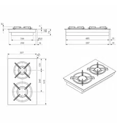
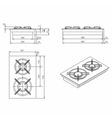
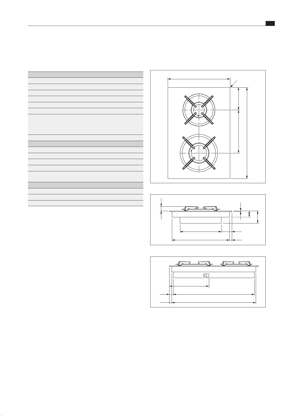
3 Technical data
Appliance dimensions
R3
370
133,5 255,5
540
Fig. 3.1 PKG3 appliance dimensions from above
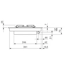
246
341
62
14,5
7
25
73
37
Fig. 3.2 PKG3 appliance dimensions front view
491
509
15,5
24,5
240
Fig. 3.3 PKG3 appliance dimensions side view
3.1 BORA Pro gas cooktop PKG3
Parameter Value
Supply voltage 220–240V
Frequency 50/60Hz
Total burner output 5.0kW
Power rating 20W
Fuse protection 1 x 0.5A
Gas connection 1/2“ internal thread
Dimensions (width x depth x height)
cooktop
pan support high-power burner
pan support normal burner
370 x 540 x 73mm
270 x 270 x 25/50mm
235 x 235 x 25/50mm
Weight (incl. accessories/packaging) 11.5kg
Cooktop
Power levels 1–9, P
Heat retention levels 3
Front high-power burner 800–3000W
Normal rear burner 550–2000W
Total nominal connection values
G20/20mbar:
5.00kW
0.449m³/h
Cooktop energy consumption G20/20mbar
Front high-power burner 850 – 3000 W 60,0 %
Normal rear burner 700 – 2000 W 60,0 %
Total (average) 60,0 %
Tab. 3.1 Technical data
Additional technical data for Australia and New Zealand
(AUS/NZS):
Total nominal connection values for natural gas/
1.0 kPa test point pressure: 19.5 Mj/h
Cooktop energy consumption AUS/NZS natural gas/
1.00 kPa test point pressure:
High power front burner 12.0 Mj/h
Normal back burner 7.5 MJ/h
EN
12
Technical data
www.bora.com
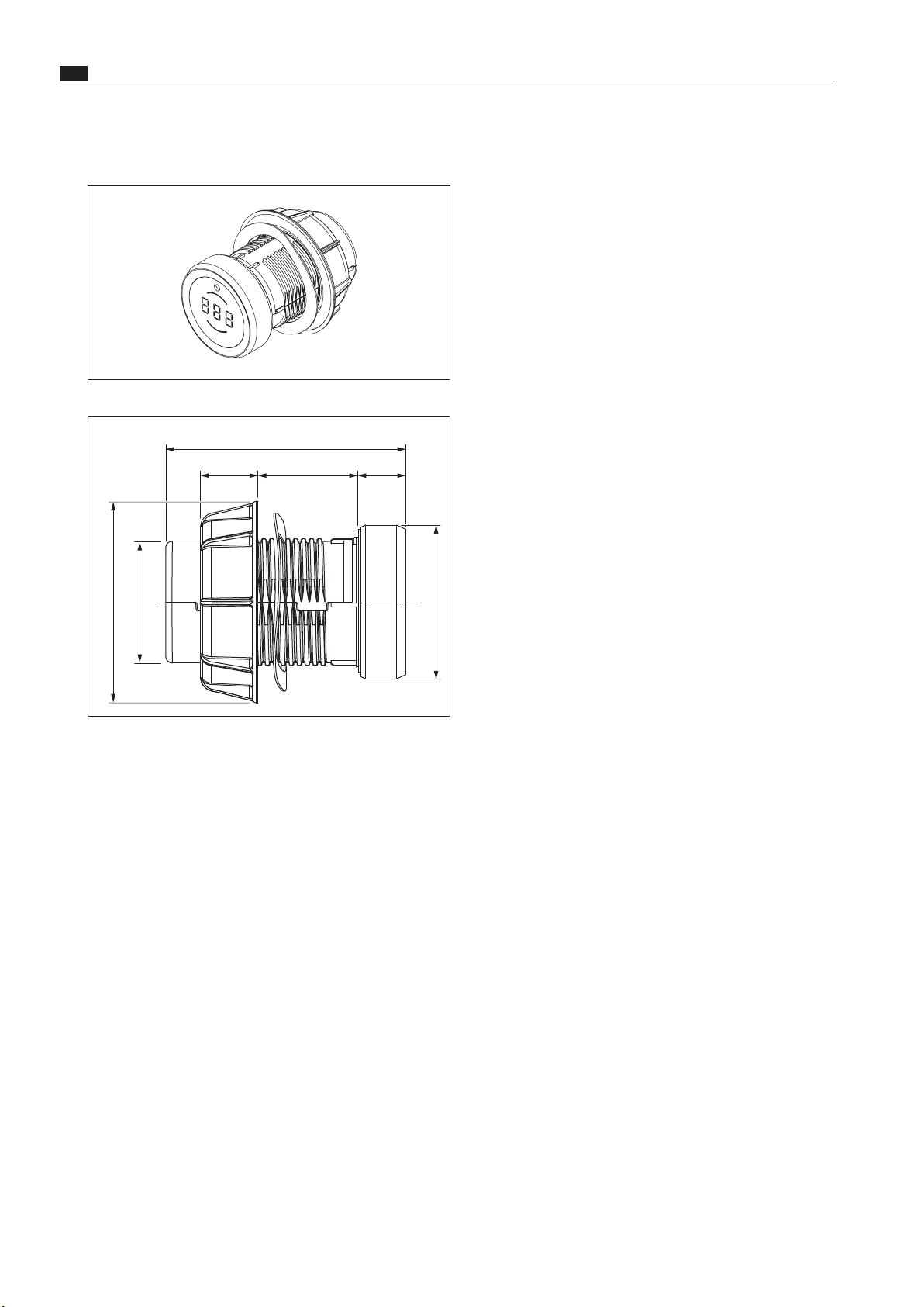
3.2 BORA Professional 3.0 control
knob dimensions
Fig. 3.4 Control knob
Ø49
Ø58
Ø76
90
22 10-40 18
Fig. 3.5 Control knob dimensions
EN
13
Appliance description
www.bora.com
4 Appliance description
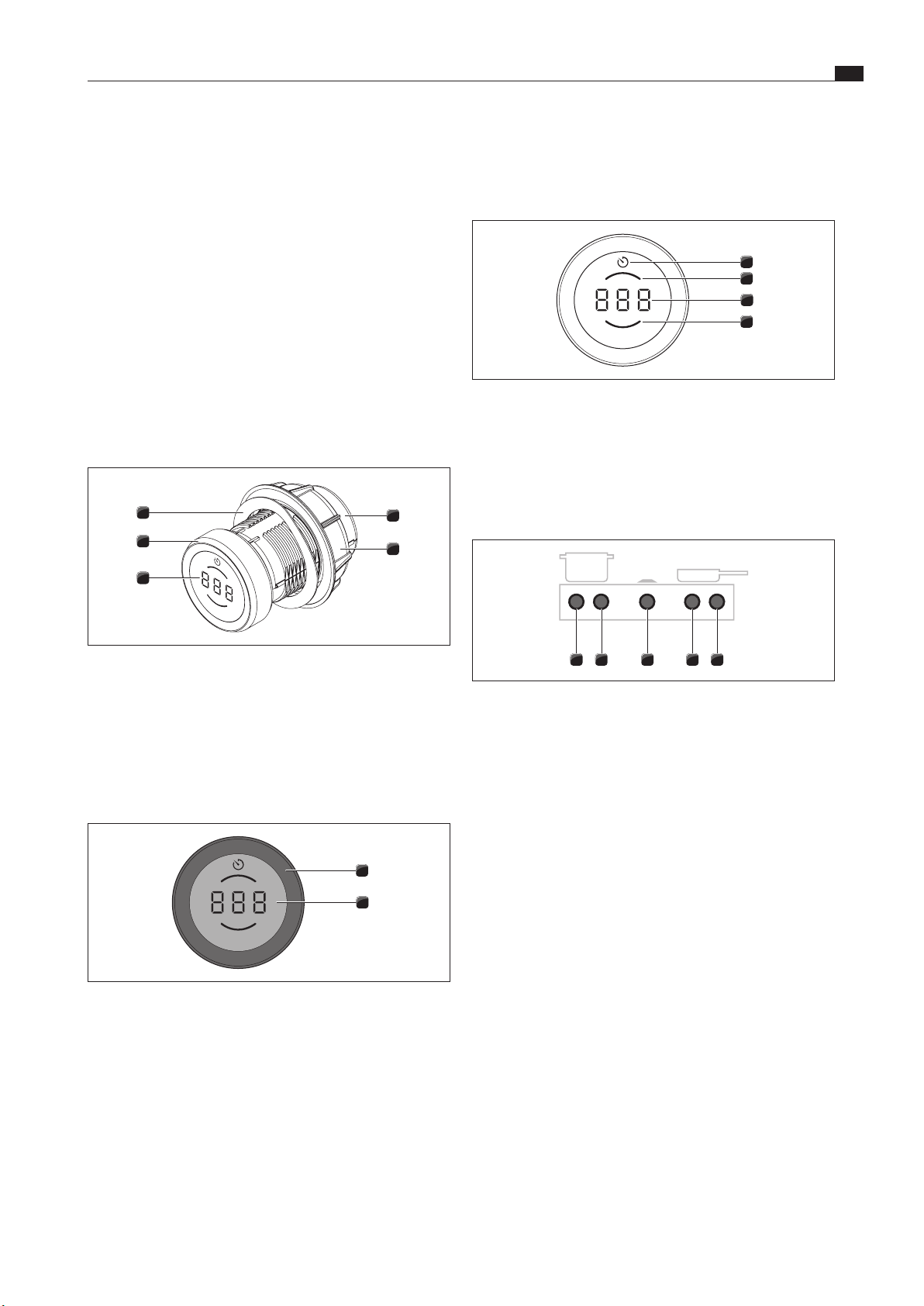
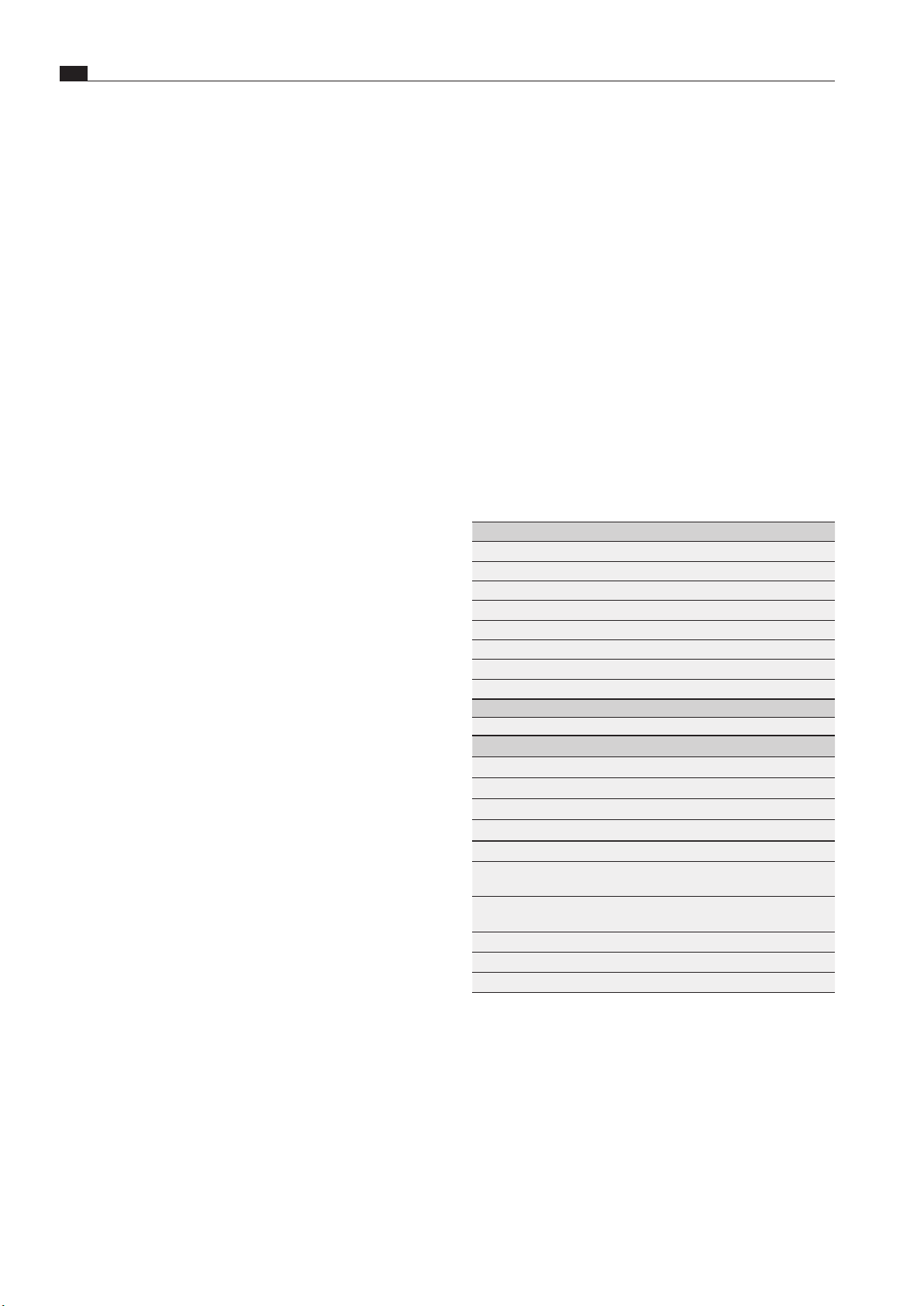
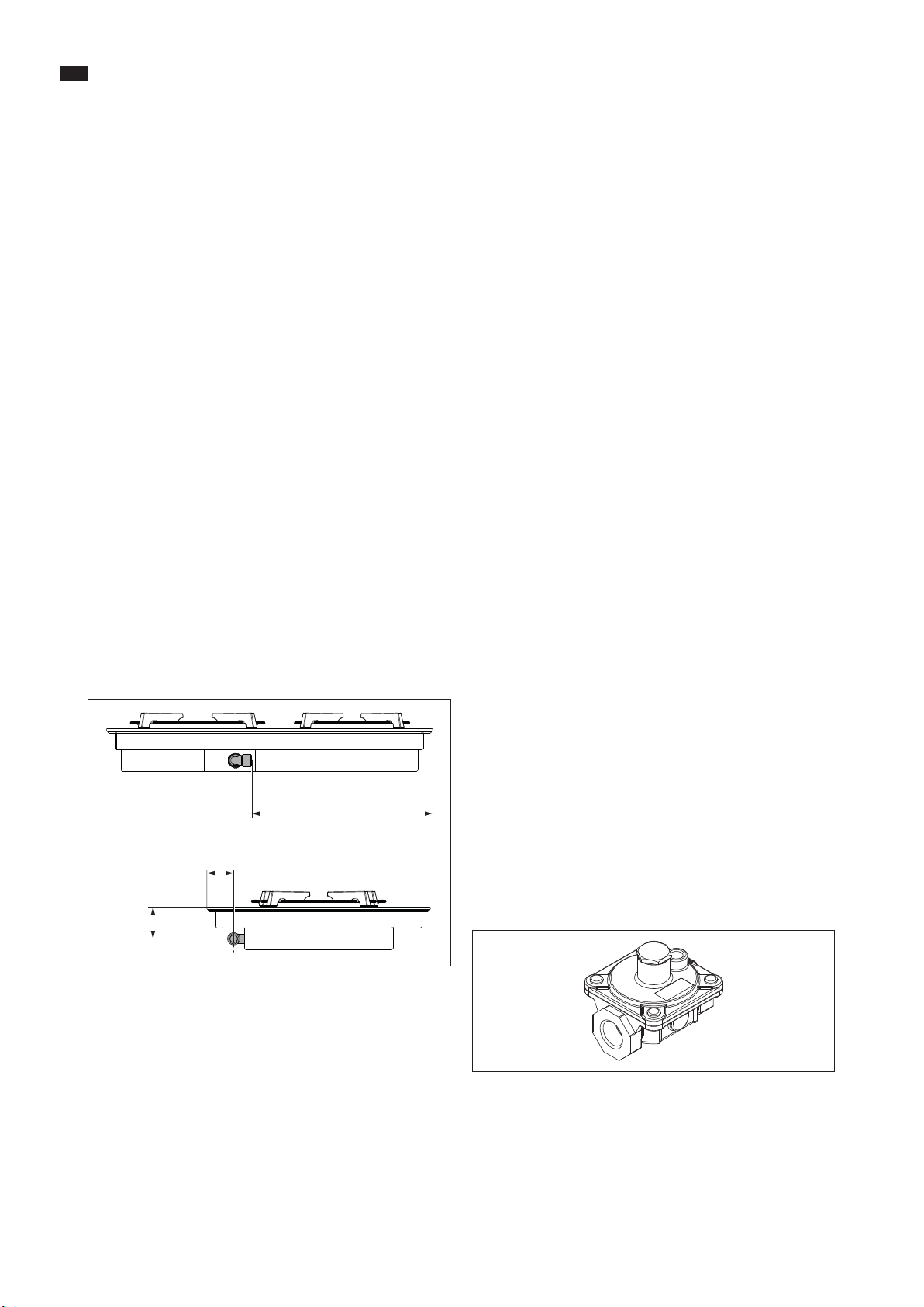
Control knob display
3
1
2
4
Fig. 4.3 Control knob display elements
[1] Timer/egg timer indicator
[2] Rear cooking zone indicator
[3] Multi-function display
[4] Front cooking zone indicator
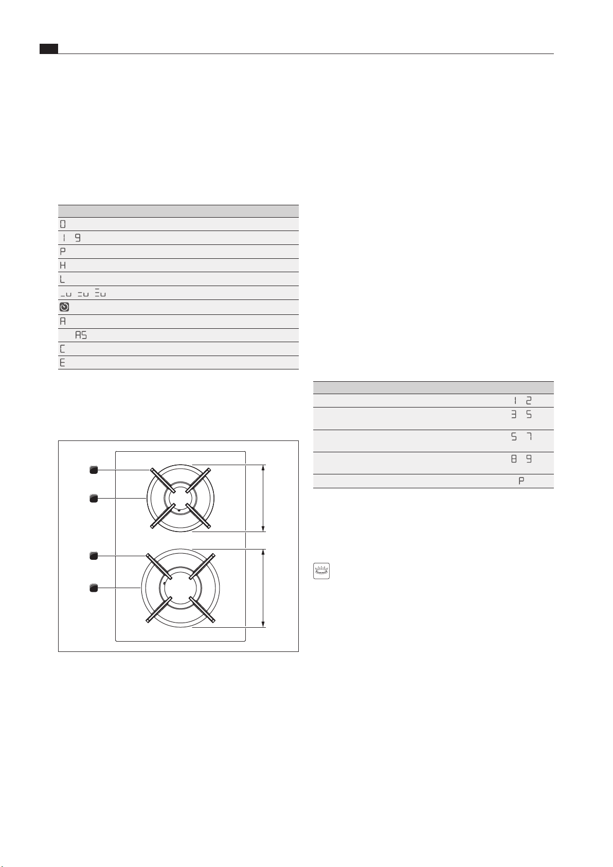
Control knob assignment
54321
Fig. 4.4 Control knob assignment
[1] Control knob for left cooktop, front cooking zone
[2] Control knob for left cooktop, rear cooking zone
[3] Control knob for cooktop extractor
[4] Control knob for right cooktop, front cooking zone
[5] Control knob for right cooktop, rear cooking zone
X
Observe all safety and warning information during operation
(see the Safety chapter).
4.1 Control knob
How it works
The cooktop extractor and cooktops are operated with a control
knob. The power levels and functions are controlled by turning
the knob ring and pressing the touch surface.
i
How it works and its functions are described in more
detail in the Operation chapter.
Structure
4
3
5
2
1
Fig. 4.1 Control knob structure
[1] Knob housing
[2] Universal nut
[3] Control knob display
[4] Knob ring
[5] Wave spring
Operating elements
2
1
Fig. 4.2 Control knob operating elements
[1] Knob ring
[2] Touch surface
EN
14
Appliance description
www.bora.com
4.2.1 How gas cooktop PKG3 works
If a cooking zone is switched on, the flame generates heat,
which directly heats the base of the cookware. The gas flame
is controlled by a highly accurate electronic gas control system
(e-gas system). Among other things, servomotors are used to
accurately control each gas burner. These servomotors calibrate
themselves from time to time and typical humming noises
can be heard that are totally normal and do not constitute a
malfunction.
The advantage of this electronic gas control system is the
optimum, repeatable heat regulation, which means that the
selected power levels are identical in every cooking session. In
addition, a clean, constantly increasing flame is formed at every
power level. Furthermore, if necessary, it can be automatically
reignited. This control ensures that the numerous operating
functions of the cooktop can be adjusted using the control
knobs. The power is controlled via power levels 1–9 and P.
Power levels
The power output of gas cooktops results in food being heated
quickly. In order to avoid burning food, slight adjustment is
needed in comparison to conventional cooking systems when
selecting the power level.
Activity Power levels
Keeping cooked meals warm
1
–
2
Browning chopped vegetables, fried eggs, veal,
poultry
3
–
5
Grilling prawns, corn on the cob, schnitzel, beef,
fish or burgers
5
–
7
Bringing large amounts of liquid to the boil,
searing steaks
8
–
9
Heating up water
ßp
Tab. 4.2 Recommendations for power levels
The specifications provided in the table are standard values.
Suitable cookware
Cookware with this symbol is suitable for gas cooktops.
i
The heating and heat-through times for the cookware
base, as well as the cooking results, are significantly
influenced by the structure and material of the cookware.
Cookware with a thick base ensures more even heat
distribution. In the case of a thin base there is a risk of
the food becoming overheated in places. The cooktop
may also become damaged.
i
Take special care not to overheat the cookware. Never
heat empty cookware. The base can become deformed.
i
Cookware with an uneven base may tip over. A slight
wobble can never be completely ruled out.
4.2 Cooktop appliance description
Display and symbols
i
The power levels and cooking functions of each cooking
zone are shown in the control knob display on the
corresponding control knob.
Control knob display
Indicator Meaning
0
Cooktop is switched off
1
–
9
Power levels
ßp
Power setting
H
Residual heat indicator
L
Childproofing feature
,
v
/
:
v
/
*
v
Heat retention levels active
Timer function active
A
Automatic heat up function
e.g.
A
5
Automatic heat up function active
C
Configuration menu
E
...
Error message (see the Troubleshooting chapter)
Tab. 4.1 Control knob display
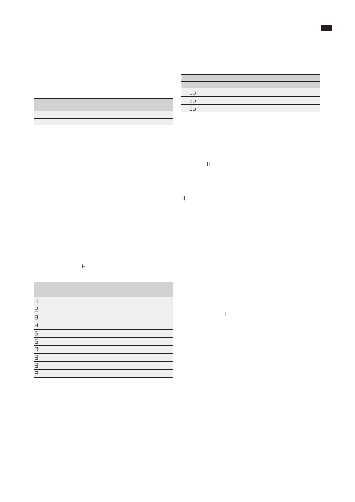
Layout and size of the cooking zones
Gas cooktop PKG3
1
2
4
3
200240
Fig. 4.5 Layout of gas cooktop PKG3 and cooking zone
dimensions
[1] High-power front burner
[2] Front pan support
[3] Normal back burner
[4] Rear pan support
EN
15
Appliance description
www.bora.com
i
After 20 minutes, the power setting is automatically
switched back to power level 9.
PKG3:
Heat retention level Switch off after hours:minutes
1 (
,
v
)
8:00
2 (
:
v
)
8:00
3 (
*
v
)
8:00
Tab. 4.5 Safety shut-down on the different heat retention levels
X
Switch the cooking zone back on if you want to put the
cooking zone back into operation (see the Operation chapter).
Residual heat indicator
i
While
H
is displayed (residual heat indicator), do not
touch the cooking zone or place any heat-sensitive
objects on top of it. Risk of burns and fire!
After switching it off, the cooking zone remains hot.
H
is displayed (Residual heat indicator).
After a sufficient cooling period the indicator will go out
Overheating protection
i
If the cooktop overheats, the power is reduced or the
cooktop is switched off completely.
The appliance is fitted with overheating protection. The
overheating protection can be triggered if:
O
cookware is heated up empty;
O
oil or fat is heated on high power;
O
a hot cooking zone is switched on again after a power cut.
Whilst the overheating protection is active, one of the following
steps is taken:
O
the activated power setting is switched back to the previous
level;
O
the power setting
ßp
can no longer be switched on;
O
the set power level is reduced;
O
the cooktop switches off completely.
After a sufficient cooling period, the cooktop can be used again.
Childproofing feature
i
If a single cooktop is operated without a cooktop
extractor, removal of the knob ring can prevent the
appliance from being switched on accidentally or without
permission.
Suitable cookware is made of:
O
copper
O
stainless steel
O
aluminium
O
cast iron
X
Adhere to the dimensions in the table:
Burner position Recommended pan
diameter
Minimum pan
diameter
Normal burner 140–200mm 120mm
High-power burner 180–240mm 160mm
Tab. 4.3 Pan diameters
i
Only use cookware with a diameter that is within the
given dimensions (see the Suitable cookware chapter). If
the diameter is too large, the hot gases flowing outwards
from under the base may damage the worktop or any
non-heat-resistant wall, e.g. with panelling, as well as
part of the cooktop and the cooktop extractor. Bora shall
not be held liable for any such damage.
4.3 Safety devices
Safety shut-down
If an appliance is switched on but is not used for a predefined
time, it is automatically switched off.
Cooktops
Each cooking zone is switched off automatically when the cooking
zone exceeds the maximum operating duration on one power level
or heat retention level.
H
is displayed (Residual heat indicator).
PKG3:
Power levels Safety shut-down after hours:minutes
1
8:24
2
6:24
3
5:12
4
4:12
5
3:18
6
2:12
7
2:12
8
1:48
9
1:18
ßp
0:20
Tab. 4.4 Safety shut-down on the different power levels
EN
16
Installation
www.bora.com
5 Installation
i
Assembly, installation and commissioning must always
occur in line with national laws, regulations and
standards.
i
The work must be performed by qualified specialists who
know and comply with the additional regulations of the
local energy supply companies.
i
The appliance must only be used in well-ventilated rooms.
X
Observe all safety and warning information (see the “Safety”
chapter).
X
Follow the enclosed manufacturer’s information.
X
Before connecting the appliance, check that the appliance
settings comply with local connection requirements (gas type
and pressure).
X
Do not leave small children unattended near the appliance!
5.1 General installation instructions
i
The appliances must not be installed above cooling
devices, dishwashers, stoves, ovens, washing machines
or dryers.
i
The contact surfaces of the worktops and wall sealing
strips must be made of a heat-resistant material (up to
approx. 100°C).
i
Worktop cut-outs must be moisture-sealed using suitable
means and, where necessary, fitted with a thermal
insulator.
i
External devices may only be connected to the cooktop
extractor connections provided.
i
Extremely bright lights aimed directly at the appliances
can cause colour variations in the appliances and are
thus to be avoided.
General installation instructions for cooktops
i
To ensure that the cooktops perform optimally at all
times, there must be sufficient ventilation beneath the
cooktops.
i
The performance of the cooktops is affected or the
cooktops overheat if the warm air beneath the cooktops
cannot escape.
i
If a cooktop overheats, the power is automatically
reduced or the cooktop is switched off completely (see
“Overheating protection”).
i
If cable protection (false floor) is planned beneath the
appliance, this must be fitted so it does not obstruct
ventilation.
Additional installation notes for Australia and New Zealand
(AU/NZ):
i
The gas hose must be inspected every 5 years and
replaced if necessary. The gas hose must meet the
requirements of AS/NZS 1869.
5.2 Checking the scope of delivery
X
Make sure the delivery is complete and check it for damage.
X
If there are any missing or damaged parts, please notify the
BORA After Sales Service.
X
Do not under any circumstances install parts which are
damaged.
X
Dispose of transport packaging in the proper manner (see the
“Decommissioning, disassembly and disposal” chapter).
Name Quantity
Cooktop 1
Control knob 2
Operating and installation instructions 1
Cooktop mounting screws 4
Height adjustment plate set 1
Cooktop mounting straps 4
Control knob cable 2
Cooktop to cooktop extractor communication cable 1
Special scope of delivery for glass ceramic cooktops
Glass ceramic cleaning instructions 1
Special scope of delivery for gas cooktops
Cast-iron grate 2
Nozzle set G20/20mbar natural gas PKGDS2020 1
Cylindrical/conical transition piece 1
Seal 1
Special scope of delivery for Australia and New Zealand:
Gas regulator 1,00 kPa
with test point for natural gas (NG)
1
Flexible gas connection hose, length 500mm, 1/2”
external thread (EN14800)
1
Test point adapter for liquid gas (LPG) 1
Nozzle set G20/10 mbar (NG/1.0 kPa) – pre installed 1
Nozzle set G31/27,5 mbar (ULPG/2.75 kPa) 1
Tab. 5.1 Scope of delivery of the cooktops
5.3 Tools and aids
The following tools are required to correctly install the appliance:
O
pencil
O
tape measure or folding metre stick
O
standard or cordless drill with Ø50mm Forstner bit
O
black, heat-resistant silicone sealant
O
slotted screwdriver
O
size 20 Torx screwdriver
EN
17
Installation
www.bora.com
min.
700*
min.
74
176
900
(min.
890)
**
120
252
285
min.
100
170
682
max.
562
max.
430
389
*
110
PKA3
mit
Flachschalldämpfer
USDF,
Flachkanalverbinder
EFV
und
Übergangsstück
Versatz
EFRV110
(Zeile):
PKA3
mit
Rundschalldämpfer
USDR50
und
Rundkanal-
verbinder
ERV
(Insel):
PKAS3
mit
Ecotube
Flachkanal:
PKA3
mit
Flachschalldämpfer
USDF,
Flachkanalverbinder
EFV
und
Übergangsstück
gerade
EFRG
(Insel):
min.
700
min.
74
199
min.
100
120
691
min.
455
58
min.
328
max.
580
592
152
min.
810*
min.
74
176
900
(min.
890)
**
220
min.
100
110
760
max.
545
219*151*
BORA
Professional
3.0
BORA LÜFTUNGSFIBELXX
min.
810*
min.
74
176
900
(min.
890)
**
120
min.
100
93
min.
742
max.
562
219*151*
295
33
180
810
Abb. 5.3 Appliance installation dimensions for standard set-up
of PKA3/PKA3AB with round silencer USDR50
5.4.3 Worktop and kitchen units
X
Create the worktop cut-out taking into account the specified
cut-out dimensions.
X
Make sure that the cut surfaces of the worktops are properly
sealed.
X
Comply with the instructions of the worktop manufacturer.
O
Cross bars on the kitchen unit in the area of the worktop cut-
out may need to be removed.
O
No false floor is necessary below the cooktop. If cable
protection (false floor) is planned, the following must be taken
into account:
O
it must be fitted in such a way that it can be removed for
maintenance work;
O
to ensure sufficient cooktop ventilation, a minimum
distance of 15mm to the bottom edge of the cooktop is
to be observed.
O
The drawers and/or shelves in the floor unit must be
removable.
O
For correct installation, the drawers of the floor unit must be
shortened depending on the installation situation.
5.4.4 Special installation instructions for gas
cooktop PKG3
i
Taking into account the applicable valid regulations,
the cooktop must be connected to the gas line with an
upstream stopcock.
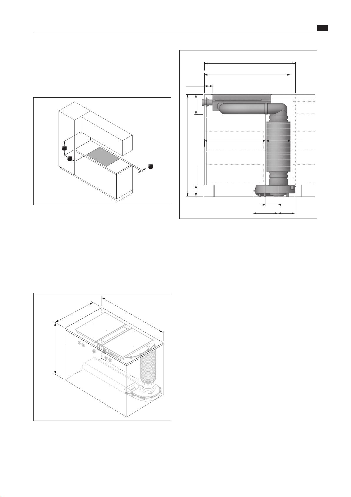
5.4 Assembly instructions
5.4.1 Safety clearances
X
Maintain the following safety clearances:
1
3
2
Abb. 5.1 Minimum distance
[1] Minimum clearance of 50mm at the back from the worktop
cut-out to the rear edge of the worktop.
[2] Minimum clearance of 300mm from the left and right of the
worktop cut-out to the adjacent cabinet or wall.
[3] Minimum clearance of 650mm between the worktop and the
wall unit.
5.4.2 Minimum installation dimensions
(standard set-up)
≥810
≥890
≥900
Abb. 5.2 Minimum installation dimensions for standard set-up
of PKA3/PKA3AB
EN
18
Installation
www.bora.com
2
1
Abb. 5.6 Plinth area air supply
[1] Optional cable protection (shortened)
[2] Air supply via the plinth area (opening cross-section
≥150cm²)
i
To ensure a sufficient air supply, an opening cross-
section of at least 50cm² is recommended in the front of
the kitchen unit, or an opening cross-section of at least
150cm² in the plinth area.
X
Make sure that the area below the cooktop has a sufficient air
supply.
5.4.5 Recirculation when using the cooktop
extractor as a recirculation system
In the case of recirculation systems there must be a return flow
aperture in the kitchen units:
O
>1000cm² (per air cleaning box) in combination with gas
cooktop PKG3
i
If several extractor systems are operated in recirculation
mode, the return flow aperture for each air cleaning box
must be calculated accordingly. Example: 2 recirculation
systems =2 x (>1000cm²)
For recirculation, the necessary return flow aperture can be
created using a shortened plinth. A slatted plinth with at least
the minimum opening cross-section can also be used.
i
The hose connection must be laid in such a way that it is
not subject to deformation, buckling or abrasion.
i
The stopcock and gas supply pipe connections must be
accessible.
i
The pressure regulator must correspond to the set gas
type and set gas pressure and must meet local and legal
requirements.
i
The gas connection hose line must not come into contact
with smoke or the flue outlet of an oven.
i
The hose must not come into contact with hot surfaces
on the cooktop or other appliances.
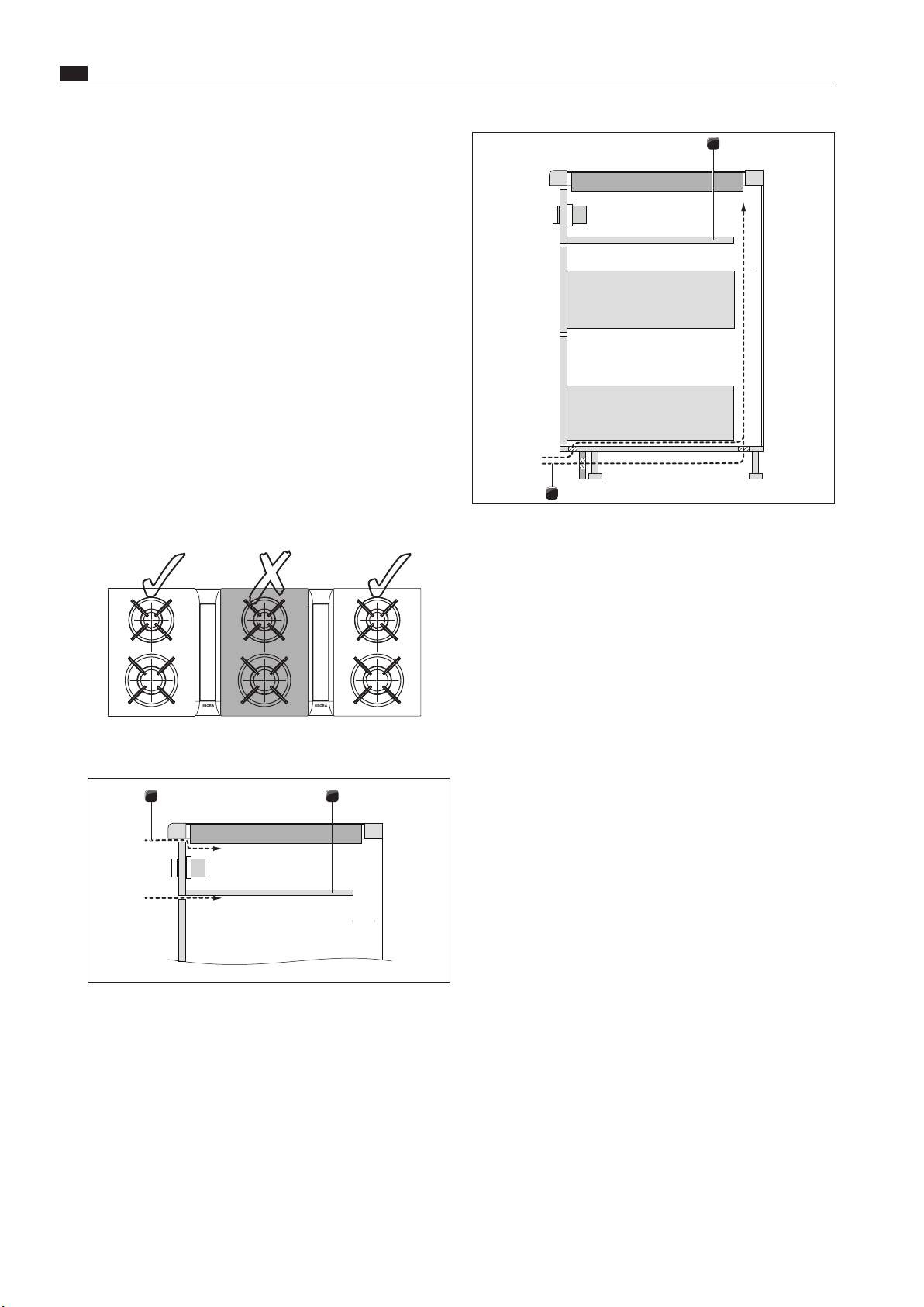
Positioning of the gas cooktop PKG3 with two
cooktop extractors
If the gas cooktop is used in a model with two cooktop
extractors, it is to be installed at the side. If installed between
the cooktop extractors, the pull of air from both sides may affect
the flames.
Abb. 5.4 Position of the PKG3 with two cooktop extractors
Air supply for gas cooktop PKG3
1 2
Abb. 5.5 Air supply at front of the unit
[1] Air supply via the front of the unit (opening cross-section
≥50cm²)
[2] Optional cable protection (shortened)
EN
19
Installation
www.bora.com
i
In the case of cooktop extractor PKA3/PKA3AB
combined with straight duct piece PKA1FEV, flush
installation is also possible in a worktop with a depth
≥650mm.
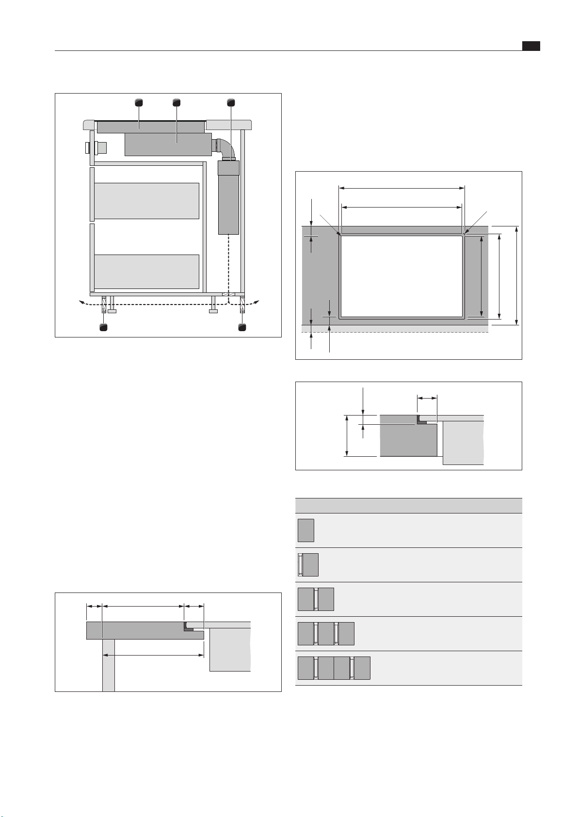
5.5.1 Flush installation
x
A ±2
B ±2
544 ±2
≤ R5
≤ R5
≥ 74
(≥ 70)
516 ±2
≥ 700
Abb. 5.9 Cut-out dimensions for ush installation
7 +0,5
14
10 - 40
Abb. 5.10 Rebate dimensions for ush installation
Cooktops/cooktop extractor A in mm B in mm
1/0 374 346
1/1 485 457
2/1 856 828
3/2 1338 1310
4/2 1709 1681
Tab. 5.2 Cut-out dimensions of the appliance combinations in the
case of ush installation
1 32
44
Abb. 5.7 Recirculation design example (kitchen isl
and + PKG3 +
PKAS3 + air cleaning unit)
[1] Gas cooktop PKG3
[2] Cooktop extractor PKAS3 (recirculation)
[3] Air cleaning box (ULBF, ULB3)
[4] Recirculation return flow aperture (total opening cross-section
≥1000cm² per air cleaning unit)
X
Ensure that the return flow aperture is large enough
i
If the gas flame goes out or there is a high burner flame
delay, the return flow aperture must be enlarged.
5.5 Cut-out dimensions
i
All dimensions are shown from the front edge of the front
panel.
Worktop overhang
≥60
(
≥74
)
14x
Abb. 5.8 Worktop overhang
X
Please note the worktop overhang x when creating the
worktop cut-out. Applies to flush installation and surface
mounting.
EN
20
Installation
www.bora.com
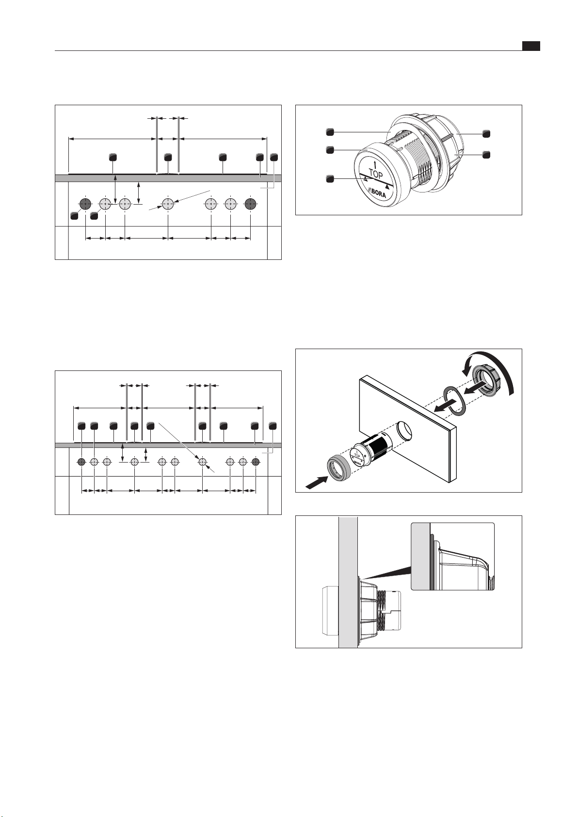
5.6 Installing the control knob in the
floor unit front panel
Abb. 5.13 Installed control knob
X
Pre-drill all bore holes to prevent tearing out the fixed front
panel.
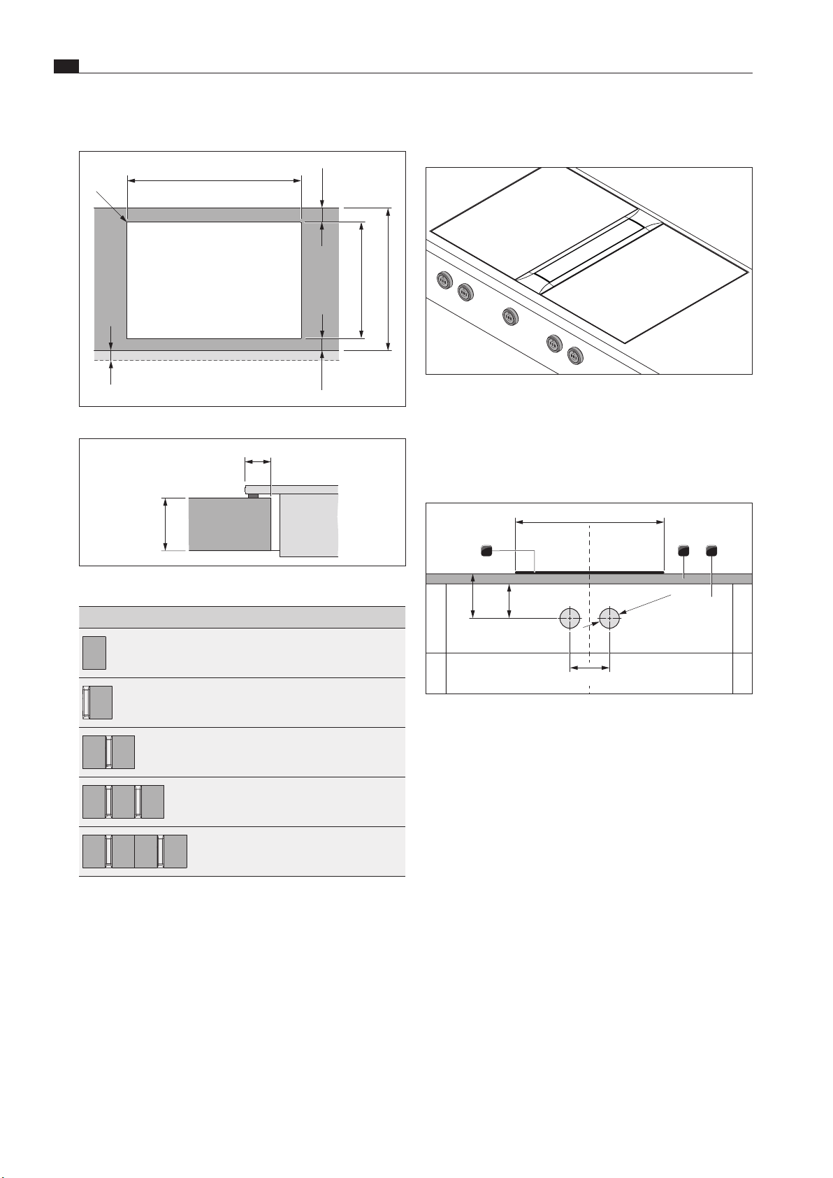
5.6.1 Cooktop bore holes
≥40≥70
Ø50 ±0,5
370
80-140
1 2 3
Abb. 5.14 Cooktop drilling pattern
[1] Cooktop
[2] Worktop
[3] Fixed front panel
5.5.2 Surface mounting
x
B ±2
≤ R5
≥ 74
(≥ 70)
516 ±2
≥ 700
Abb. 5.11 Cut-out dimensions for surface mounting
12
10 - 40
Abb. 5.12 Overlay dimensions for surface mounting
Cooktops/cooktop extractor B in mm
1/0 346
1/1 457
2/1 828
3/2 1310
4/2 1681
Tab. 5.3 Cut-out dimensions of the appliance combinations in the
case of surface mounting
EN
21
Installation
www.bora.com
5.6.3 Fitting the control knob
4
3
5
2
1
Abb. 5.17 Structure of control knob
[1] Knob housing
[2] Universal nut
[3] Sticker
[4] Knob ring
[5] Wave spring
i
In the case of steel fronts, wave springs must not be
used. The corresponding installation steps are to be
omitted.
Abb. 5.18 Fitting the control knob
Abb. 5.19 Wave spring when installation is complete
X
Remove the knob ring [4].
X
Unscrew the universal nut [2].
X
Remove the wave spring [5].
X
Insert the knob housing [1] from the front through the hole in
the panel.
X
Attach the wave spring [5] to the knob housing [1] from the
rear (not in the case of steel fronts).
X
Screw the universal nut [2] onto the knob housing [1] from the
rear and tighten a little.
5.6.2 Example bore holes
≥40≥70
90 90 90
Ø50 ±0,5
90 196 196
370 370
110
1 1
3
1 2
4 3 65
Abb. 5.15 Drilling pattern for 2 cooktops, 1 cooktop extractor
and 2 sockets
[1] Boreholes for socket (x 2 external)
[2] Bore holes for control knobs (x 5)
[3] Cooktop (x 2)
[4] Cooktop extractor
[5] Worktop
[6] Fixed front panel
≥70 ≥40
90 90 909090 196 196 196 196
370 370
370
110
1 1 1 1
110
Ø50 ±0,5
3 31 2 4 4 3 65
Abb. 5.16 Drilling pattern for 3 cooktops, 2 cooktop extractors
and 2 sockets
[1] Boreholes for socket (x 2 external)
[2] Bore holes for control knobs (x 8)
[3] Cooktop (x 3)
[4] Cooktop extractor (x 2)
[5] Worktop
[6] Fixed front panel
EN
22
Installation
www.bora.com
X
Align the knob housing [1] so it is level.
X
Tighten the universal nut [2].
O
The wave spring (if used) must be pressed flat.
X
Remove the sticker [3].
X
Place the knob ring [4] on the knob housing [1].
5.7 Gas installation
i
Assembly, installation and commissioning must always
occur in line with national laws, regulations and
standards.
i
The work must be performed by qualified specialists who
know and comply with the additional regulations of the
local energy supply companies.
i
The gas must be connected before the cooktop is
installed in the worktop.
Ventilation
This appliance is not connected to a flue gas evacuation device.
It must be positioned and connected in accordance with the
applicable installation conditions. Suitable ventilation measures
must be particularly adhered to.
X
Always ensure there is sufficient ventilation when operating
the appliance.
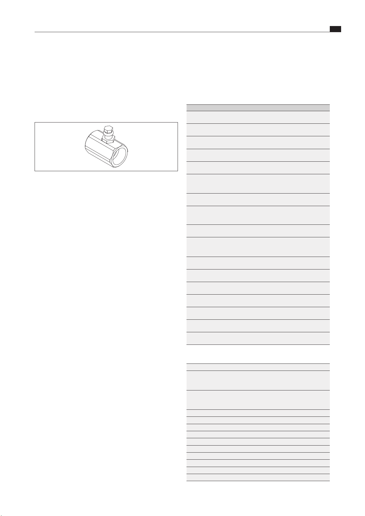
5.7.1 Gas connection
45
300
53
Abb. 5.20 Position of gas connection
The gas supply is connected to the appliance using a pre-
installed elbow fitting with a 1/2” cylindrical internal thread. If,
due to national regulations, a conical connection is required, the
cylindrical/conical transition piece (provided) is to be used.
5.7.2 Connecting the gas supply
X
Turn off the gas supply.
X
Switch off the main switch/automatic circuit breaker before
connecting the cooktop.
X
Secure the main switch/automatic circuit breaker against
being switched back on without permission.
X
Make sure the power to the appliance is disconnected.
X
Check the gas type and gas pressure of the gas supply pipe.
X
Ensure that the appliance is equipped with the correct nozzle
type in order to guarantee a correct burner flame and safe
operation.
X
Remove the protective cap from the elbow fitting.
X
Connect the appliance to the gas supply.
X
Use suitable testing equipment to check all the connections
between the cooktop and the gas connection. There must not
be any leaks.
X
Create a leak test record and give this to the user.
5.7.3 Additional installation notes for
Australia and New Zealand (AU/NZ)
i
Observe the requirements on the installation of the
appliance pursuant to AS/NZS 5601.1: minimum
clearance of the gas burner head from flammable
surfaces.
i
Installation must only be carried out by authorized
personnel.
X
In addition, adhere to the requirements of the currently
applicable version of the regulations and AS/NZS 5601.1 .
X
Further technical requirements are considered:
AS/NZS 5263.1.1 Gas appliances - Domestic gas cooking
appliances (AU/NZS ).
X
Check the different scope of delivery (see scope of delivery of
the cooktops)
O
The connection to a rigid and bend-resistant pipe must be
established as specified in AS/NZS5601.1.
O
Pursuant to AS/NZS 1869 (certified to AS/NZS 1869), the
connection to a hose for gas must have a diameter of 10mm,
a class B or D classification in accordance with AS/NZS 1869
and a maximum length of 1,200mm in accordance
with AS/NZS 5601.1.
Natural gas (NG)
If the cooktop is connected to a natural gas (NG) supply, a gas
regulator must be installed with a test point.
The gas regulator comes with the appliance.
Abb. 5.21 Gas regulator (NG)
X
Attach the gas regulator to the gas cooktop connection.
X
Note the gas flow direction of the gas regulator.
EN
23
Installation
www.bora.com
Liquid gas (LPG)
i
When converting from NG to ULPG, the sticker in the
enclosed pack must be attached.
If the cooktop is attached to a liquid gas supply (LPG), the supply
is controlled on the gas bottle.For this purpose, install only the
test point adapter in the gas supply pipe.The test point adapter
comes with the appliance.
Abb. 5.22 Test point adapter (LPG)
X
Attach the test point adapter to the gas cooktop connection.
Check the gas pressure (LPG) as follows:
X
Set the control knob to the 0 position.
X
Close the gas supply.
X
Unscrew the test point screw completely.
X
Connect your measuring device to the test point connection.
X
Open the gas supply.
X
Set the gas pressure at the gas supply pipe
(LPG pressure bottle) to 2.75 kPa.
X
Ignite the burner (see the Operation section).
X
Check the burner flame.
X
Close the gas supply after successfully setting the pressure.
X
Set the control knob to the 0 position.
X
Shut off the measuring device from the test point.
X
Securely screw the test point screw back into the test point
adapter.
X
Check that the screw is positioned correctly.
5.7.4 Changing the gas type
X
Turn off the gas supply to the gas supply pipe.
X
Switch off the main switch/automatic circuit breaker.
X
Secure the main switch/automatic circuit breaker against
being switched back on without permission.
X
Make sure the power to the appliance is disconnected.
Changing the gas burner nozzle in the gas burner
i
The burner nozzles, gas type and pressure may only
be changed by a certified engineer or BORA service
technician. They also assume responsibility for the proper
gas installation and commissioning.
i
The nozzles regulate the maximum gas throughflow for
each burner and gas type/pressure.
i
The gas cooktop is set by default to natural gas
G20/20mbar (pre-assembled). If another type of gas is
used, the configuration menu on the cooktop must be
adjusted accordingly.
i
Useonly stamped and approved nozzles.
Cat.
I2E+ G20/G25: 20/25 mbar,
BE, FR
I2E G20:20 mbar,
DE, LU, PL, RO
I2EK G25.3: 25 mbar,
NL
I2L G25: 25 mbar,
NL
I2ELL G20/G25: 20/25 mbar,
DE/LU
I2H G20: 20 mbar,
AT, CH, CZ, DK, EE, ES, FI, GB, GR, HR, IE, IT, LU, LT,
LV, NO, PT, RO, SE, SI, SK, TR
I3+ G30/G31: 28–30/37 mbar, BE, CH, CY, CZ, ES, FR,
GB, GR, IE, IT, LT, PT, SI, TR
I3B/P G30/31: 30 mbar,
BE, CY, CZ, DK, EE, FI, FR, GB, GR, HR, IT, LT, NL, NO,
PL, PT, RO, SE, SI, TR
I3B/P G30/31: 50 mbar,
AT, CH, DE, FR, SK
I3P G31:37mbar
BE, CH, CZ, ES, FR, GB, GR, HR, IE, IT, LT, NL, PL, PT,
SI, SK, TR
II2E+3+ G20/G25: 20/25 mbar, G30/G31: 28–30/37 mbar,
BE, FR
II2EK3B/P G25.3: 25 mbar, G30/31: 30 mbar,
NL
II2ELL3B/P G20/G25/G30: 20/20/50 mbar,
DE
II2H3+ G20:20 mbar, G30/31: 28–30/37 mbar, CH, CY, CZ,
ES, GB, GR, IE, IT, LT, PT, SI, SK, TR
II2H3B/P G20: 20 mbar, G30/G31: 30 mbar,
CY, CZ, DK, EE, FI, GR, HR, IT, LT, NO, RO, SE, SI, SK, TR
II2H3B/P G20: 20 mbar, G30/31: 50 mbar
AT, CH, SK
II2L3B/P G25: 25 mbar, G30/31: 30 mbar
RO
Tab. 5.4 Overview of gas categories
AT eingestellt: natural gas H I2H 20 mbar
BE
BE
BE
eingestellt:
ingesteld:
reglage:
Erdgas E+
Aardgas E+
Gaz naturel E+
I2E+
I2E+
I2E+
20 / 25 mbar
20 / 25 mbar
20 / 25 mbar
CH
CH
CH
eingestellt:
impostato per:
impostato per:
Erdgas H
Gas metano H
Gaz naturel H
I2H
I2H
I2H
20 mbar
CY ενεργοποιημένη: φυσικό αέριο H 20 mbar
CZ nastaveno na: Zemní plyn H I2H 20 mbar
DE eingestellt: Erdgas E I2H 20 mbar
DK sat på: Naturgas H I2H 20 mbar
EE sisse lülitatud: Maagaas H I2H 20 mbar
ES ajustado: Gas natural H I2H 20 mbar
FI asetettu: Maakaasu H I2H 20 mbar
FR reglage: Gaz naturel E+ I2E+ 20 / 25 mbar
GB set for: Natural gas H I2H 20 mbar
GR ενεργοποιημένη: φυσικό αέριο H I2H 20 mbar
EN
24
Installation
www.bora.com
HR uključeno: Prirodni plin H I2H 20 mbar
IE set for: Natural gas H I2H 20 mbar
IS sett á: jarðgas H 20 mbar
IT aggiustato a: Gas naturale H I2H 20 mbar
LT nustatytas: Gamtinės dujos H I2H 20 mbar
LU festgeluecht: Natierlech Gas E 20 mbar
LV ieslēgts: Dabasgāze H I2H 20 mbar
MT issettjat fuq: Gass naturali H 20 mbar
NO satt på: Naturgass H I2H 20 mbar
PL ustawić: Gaz ziemny E I2H 20 mbar
PT regulado para: Gás natural H I2H 20 mbar
RO setat pe: Gaz natural H I2H, I2E 20 mbar
SE sätt på: Naturgas H I2H 20 mbar
SI nastavljen na: Zemeljski plin H I2H 20 mbar
SK zapnuté: Zemný plyn H I2H 20 mbar
TR ayarlamak: Doğal gaz H I2H 20 mbar
Tab. 5.5 Gas cooktop default settings
The stamp on the nozzles corresponds to the values in the
nozzle table and can be found either on the top or side of the
nozzles.
Gas type/gas
pressurembar
Ø SR burner/
normal burner
Ø R burner/
high-power
burner
G20/20 104 125
G25/20 110 131
G20/13 115 149
G25/25 G25.3/25 104 131
G20/25 100 119
G30/37
G31/37
69 85
G30/50 G30–50mbar 62 78
Tab. 5.6 Nozzle table
Total nominal connection values for liquid gas:
Gas type mbar kW g/h m³/h
G30/G31 50 4.90 364 0.143
G30 29 5.00 364 0.143
Tab. 5.7 Liquid gas nominal connection values
Total nominal connection values for natural gas:
Gas type mbar kW m³/h
G20 20 5.00 0.48
G25 25 5.10 0.55
G25.3 25 5.10 0.54
G20 13 5.00 0.48
G25 20 4.80 0.55
Tab. 5.8 Natural gas nominal connection values
Special nozzle table for Australia and NewZealand:
AUS / NZS
gas type Ø SR burner/
normal burner
Ø R
burner
NG/1.0 kPa (G20/10) 1.22 1.55
ULPG/2.75 kPa (G31/27,5) 0.75 0.92
Tab. 5.9 Nozzle table (Australia and New Zealand)Total nominal
connection values for U-LPG/
2.75 kPa test point pressure: 18.6 Mj/h
Cooktop energy consumption AU/NZ – U-LPG/
2.75 kPa test point pressure:
High Power front burner 11.2 Mj/h
Normal back burner 7.4 Mj/h
Total nominal connection values for NG/
1.0kPa test point pressure: 19.5 Mj/h
Cooktop energy consumption AU/NZ – NG/
1.00 kPa test point pressure:
High power front burner 12.0 Mj/h
Normal back burner 7.5 Mj/h
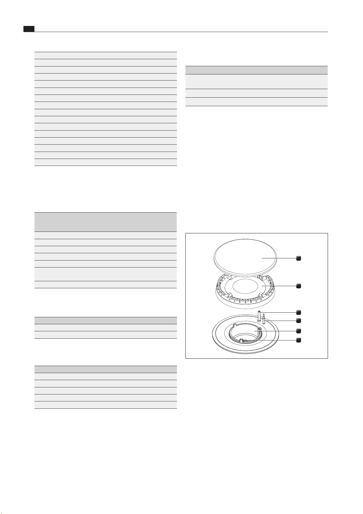
1
2
3
4
5
6
Abb. 5.23 Gas burner structure
[1] Burner cap
[2] Burner head
[3] Electric igniter
[4] Safety thermocouple
[5] Burner housing
[6] Gas burner nozzle
X
Remove the pan support.
X
Remove the burner cap [1] from the burner head [2].
X
Remove the burner head [2] from the gas outlet.
EN
25
Installation
www.bora.com
1
2
Abb. 5.24 Cooktop burner with gas burner nozzle
[1] Gas burner
[2] Gas burner nozzle
X
Unscrew the gas burner nozzle [2] from the gas burner [1]
X
Screw the corresponding nozzle for the gas type to be used
into the gas burner [2].
X
Put the burner parts back together again.
X
Position the burner head [2] correctly on the gas outlet.
X
Ensure that the safety thermocouple [4] and the electric
igniter [3] are positioned in the correct opening.
X
Position the burner cap [1] so that it fits perfectly, sitting
straight on the burner head [2].
O
If burner parts are not positioned correctly, the electric igniter
will not work.
X
Place the pan support straight on the gas burner so it fits
perfectly.
X
Set the gas type in the configuration menu (see point 5.8.4
“Configuration of gas type and gas pressure”).
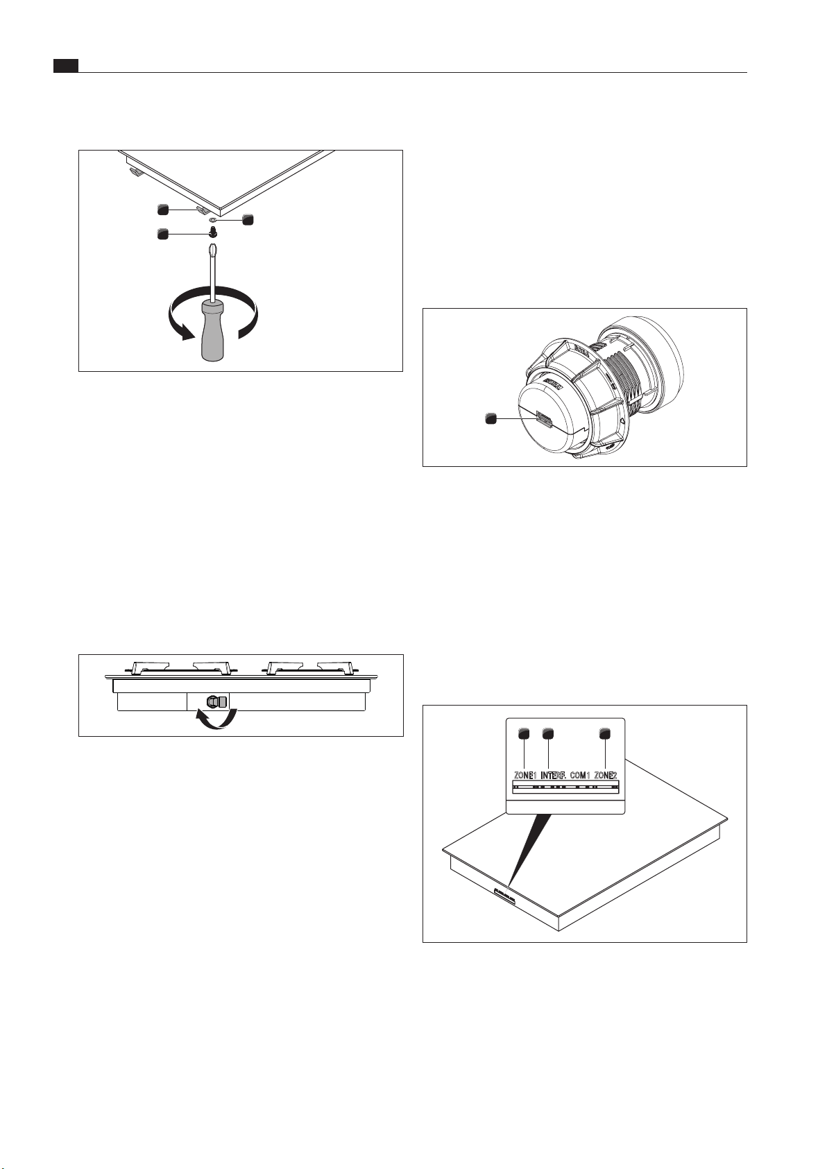
Affixing the nozzle set nameplates
X
Affix the nozzle set nameplates included in the scope of
delivery in the corresponding space over the nozzle set
nameplate on the bottom of the cooktop and on the back of
these operating and installation instructions.
Abb. 5.25 Axing the nozzle set nameplates
5.8 Installing the cooktops
i
Clearance of one millimetre should be planned between
the built-in appliances.
i
A clearance of two millimetres should be planned around
the built-in appliances.
i
It is recommended to install a mounting rail between
adjacent cooktops (mounting rail PZMS available as an
accessory).
i
The cooktop can also be installed rotated by 180°.
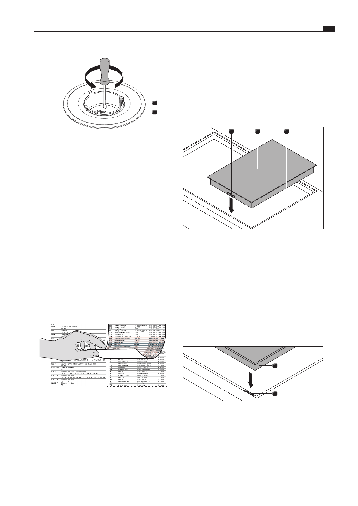
5.8.1 Installing the cooktop
Inserting the cooktop (ports on the front)
321
Abb. 5.26 Inserting the cooktop
[1] Control knob port and cooktop extractor interface (front)
[2] Cooktop
[3] Worktop cut-out
X
Insert the cooktop [2] into the worktop cut-out [3].
X
Align the cooktop [2] exactly.
X
For a normal installation, please note that the ports for the
control knobs and the automatic extractor function [1] are at
the front.
i
The connection cables should be guided to the rear. Use
the cable holders provided.
Levelling the cooktop (if necessary)
1
2
Abb. 5.27 Cooktop and height adjustment plates
[1] Cooktop
[2] Height adjustment plates
X
If applicable, insert the height adjustment plates [2].
EN
26
Installation
www.bora.com
Securing the cooktop
1
3
2
Abb. 5.28 Mounting brackets
[1] Mounting bracket
[2] Washer
[3] Screw
X
Secure the appliance using the mounting brackets [1].
X
Tighten the mounting brackets with the screw [3] using the
washer [2] with max. 2 Nm.
X
Verify that the alignment is correct.
5.8.2 Installation rotated by 180° (alternative
installation variation)
Installation rotated by 180°
X
Rotate the cooktop 180°.
Abb. 5.29 Rotating the gas elbow tting by 180°
X
Rotate the gas elbow fitting 180° so that the supply can be
connected to the rear.
X
For the installation, proceed as described above.
X
Change the installation direction in the cooktop extractor
configuration menu (see “Configuration menu” in the cooktop
extractor operating instructions).
i
If installation is rotated by 180°, then the ports for the
control knobs and the interface for the cooktop extractor
are at the rear of the cooktops.
i
Cables of sufficient length are provided.
5.9 Establishing communication and
power connection
X
Observe all safety and warning information (see the “Safety”
chapter).
O
The plug for the mains supply cable must be accessible
following installation.
O
If the mains supply cable has been damaged this must be
replaced.
i
The appliance components are linked by the ribbon cable
provided.
5.9.1 Connecting the control knobs
i
Control knobs must only be connected to the ports
provided on the appliance.
1
Abb. 5.30 Back of control knob with port
[1] Port on the back of the control knob
X
Connect the control knobs to the appliances.
Connecting the control knobs to the cooktop
i
In the normal set-up the ports are on the front of the
cooktops.
i
According to the default settings, the left control knob
operates the front cooking zone (zone 1) and the right
control knob operates the rear cooking zone (zone 2).
321
ZONE1 INTERF. COM1 ZONE2
Abb. 5.31 Ports on the cooktop
[1] Front cooking zone control knob port (zone 1)
[2] Extractor electronics interface port
[3] Rear cooking zone control knob port (zone 2)
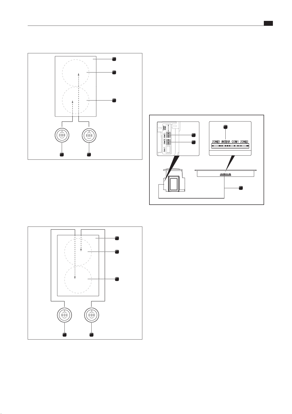
EN
27
Installation
www.bora.com
Standard cooking zone connection
5 4
3
2
1
Abb. 5.32 Standard connection of appliances that connect at
the front
[1] Cooktop
[2] Rear cooking zone (zone 2)
[3] Front cooking zone (zone 1)
[4] Rear cooking zone control knob (zone 2)
[5] Front cooking zone control knob (zone 1)
Connecting the cooking zones when the cooktop is
installed rotated by 180°
5 4
3
2
1
Abb. 5.33 Connecting the cooking zones when the cooktop is
installed rotated by 180° and the ports are on the
front of the appliance
[1] Cooktop
[2] Rear cooking zone (zone 1)
[3] Front cooking zone (zone 2)
[4] Rear cooking zone control knob (zone 1)
[5] Front cooking zone control knob (zone 2)
X
Connect the port on the back of the left control knob [5] to
the “zone 2” port on the cooktop [1].
X
Connect the port on the back of the right control knob [4] to
the “zone 1” port on the cooktop [1].
X
Using the configuration menu, set the correct allocation of the
cooking zones in the control knob display (see “Configuration
menu” – “0° or 180° installation”).
5.9.2 Establishing contact between the
cooktop extractor and cooktops
ZONE1 INTERF. COM1 ZONE2
ZONE1 INTERF. COM1 ZONE2
4
3
1
2
Abb. 5.34 Establishing contact between the cooktop extractor
and cooktops
[1] Cooktop extractor communication cable port for left cooktop
[2] Cooktop extractor communication cable port for right cooktop
[3] Cooktop communication cable port
[4] Cooktop to cooktop extractor
X
Using the communication ports provided, connect the
cooktop extractor [1]/[2] to the cooktop or cooktops [3].
X
Only use the cables supplied in the scope of delivery.
i
The full range of functions on the appliances will only
be available if the cooktop extractor and cooktops are
connected correctly.
5.9.3 Connecting the power supply
i
Assembly, installation and commissioning must always
occur in line with national laws, regulations and
standards.
i
The work must be performed by qualified specialists who
know and comply with the additional regulations of the
local energy supply companies.
i
The appliances may only be connected to the mains
power supply by certified specialists. The specialist also
assumes responsibility for the proper installation and
commissioning.
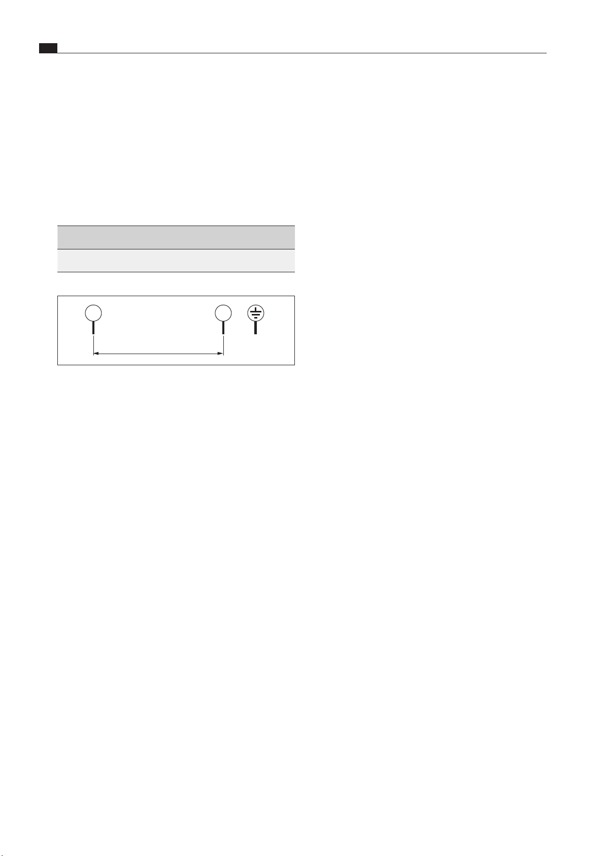
EN
28
Installation
www.bora.com
Connecting the cooktop to the power supply
The power supply cable to be used (already pre-installed) must
comply with certain, appliance-specific requirements (see table
“Fuse protection and minimum cross-section”).
i
A damaged power supply cable must be replaced by
another suitable power supply cable. This may only be
done by an authorised member of the After Sales Service
team.
Power supply cable requirements and connection diagram
Connection Fuse
protection
Wire cross
section
Power supply
cable
1-phase
connection
1 x 16 A 1.5mm² Type H05VVH2-F
Tab. 5.10 Fuse protection and minimum cross-section
1
L1
2
N
PE
220 - 240 V~
Abb. 5.35 1-phase connection diagram
Connecting the cooktop to the mains
X
Switch off the main switch/automatic circuit breaker before
connecting the cooktop.
X
Secure the main switch/automatic circuit breaker against
being switched back on without permission.
X
Make sure the power to the appliance is disconnected.
X
Only connect the cooktop using a permanent connection to a
power supply cable.
X
Check that installation has been carried out correctly.
X
Switch on the main switch/automatic circuit breaker.
X
Put the cooktop into operation (see the “Operation” chapter).
X
Check that all the functions are working correctly.
5.10 Basic configuration
When installation is complete, you must carry out the basic
settings (these settings can be changed at any time later on).
i
You can see precise instructions on the basic
configuration and all necessary information in the
“Configuration menu” chapter of the operating
instructions.
5.10.1 Gas configuration
i
The burner nozzles, gas type, gas pressure and gas
characteristic curve may only be changed by a certified
engineer or BORA service technician. They also assume
responsibility for the proper gas installation and
commissioning.
i
Gas characteristic curve A must not be used in the case
of liquid gas (G30/31).
i
It is important that the gas type, gas pressure and
characteristic curve are set correctly to ensure safe,
failure-free operation of the gas cooktop.
i
You can see detailed information on the configuration
menu in the operating instructions.
X
Enter the settings in the gas configuration menu (see
“Configuration menu” chapter).
5.11 Initial operation
i
You will find detailed information on operating the BORA
Professional 3.0 system in the operating instructions (see
“Functions and operation” chapter).
X
Ensure that all appliances are connected correctly and
connected to the power supply (fused) prior to initial
operation.
O
Exception: During initial operation, the kitchen fitter may use
a temporary power supply for the control unit in order to carry
out the basic configuration (e.g. using the site power supply
during the building phase).
O
The settings made are saved and will not be affected when the
system is disconnected from the mains.
O
The final mains connection to the appliances may only be set
up by certified specialists.
5.11.1 Using the gas cooktop for the first time
i
Initial operation is possible when the gas cooktop has
been fully installed and configured.
X
Switch the cooking zone on.
The electronic gas regulator will calibrate itself (humming noises)
and then the gas flame will automatically ignite in the selected
cooking zone.
The gas flame will burn steadily and evenly.
Using the gas cooktop together with the cooktop
extractor for the first time
X
Switch the cooktop extractor to the maximum power level.
X
Switch all cooking zones to the minimum power level.
The electronic gas regulator will calibrate itself (humming noises)
and then the gas flame will automatically ignite in the selected
cooking zone.
The gas flame will burn steadily and evenly (no reignition). The
gas flame will be slightly affected by the cooktop extractor
(airflow) – this is normal.
X
Check all the functions of the cooktop extractor and cooktop
are working correctly.
X
Check the burner flame is working correctly, particularly when
the cooktop extractor is in use.
i
If the gas flame goes out, is excessively affected by
the extractor and/or the flame is not as it should
be (e.g. soot production, flame blowback, etc.), the
characteristic curve must be increased, as well as the
ventilation in exhaust air mode, if necessary, or the
return flow aperture in recirculation mode.
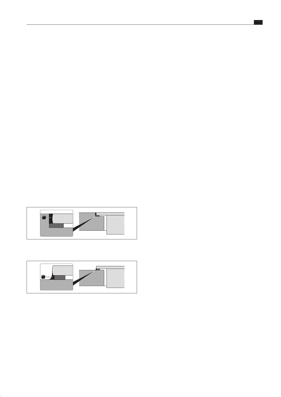
EN
29
Installation
www.bora.com
Faults during initial operation
When operating for the first time or after a prolonged period
without use or when the liquid gas bottles have been changed,
faults are possible:
The burner does not ignite. The control knob emits an
acoustic signal and the power level display flashes.
There may be air in the gas pipe.
X
Try to ignite it again by touching the control knob.
The burner does not ignite and the cooktop does not
react.
The electronic gas regulator must be recalibrated.
X
Using configuration
Ch,
reset the gas regulator.
The control knob display shows an error message (e.g.
E001).
X
Using configuration
Ch,
reset the gas regulator.
5.12 Function test
X
Carry out a thorough function test on all appliances in
accordance with se„5.11.1 Using the gas cooktop for the first
time“me”
X
In the event of error messages, see the “Troubleshooting”
chapter in the operating instructions.
5.13 Sealing the appliances
1
Abb. 5.36 Silicone sealant for ush installation
[1] Black, heat-resistant silicone sealant
1
Abb. 5.37 Silicone sealant for surface mounting
[1] Black, heat-resistant silicone sealant
X
Once all of the installation work and initial operation is
complete, seal the appliances all the way round (also between
the cooktop extractor and cooktop) with black, heat-resistant
silicone sealant [1].
X
Make sure that no silicone sealant gets under the cooktop.
5.14 Handover to user
Once installation is complete:
X
Explain the main functions to the user.
X
Explain all safety-related aspects of operation and handling to
the user.
X
Affix the supplied nameplate to the back of these instructions.
X
Provide the user with the accessories and all accompanying
documents, which are to be kept in a safe place.
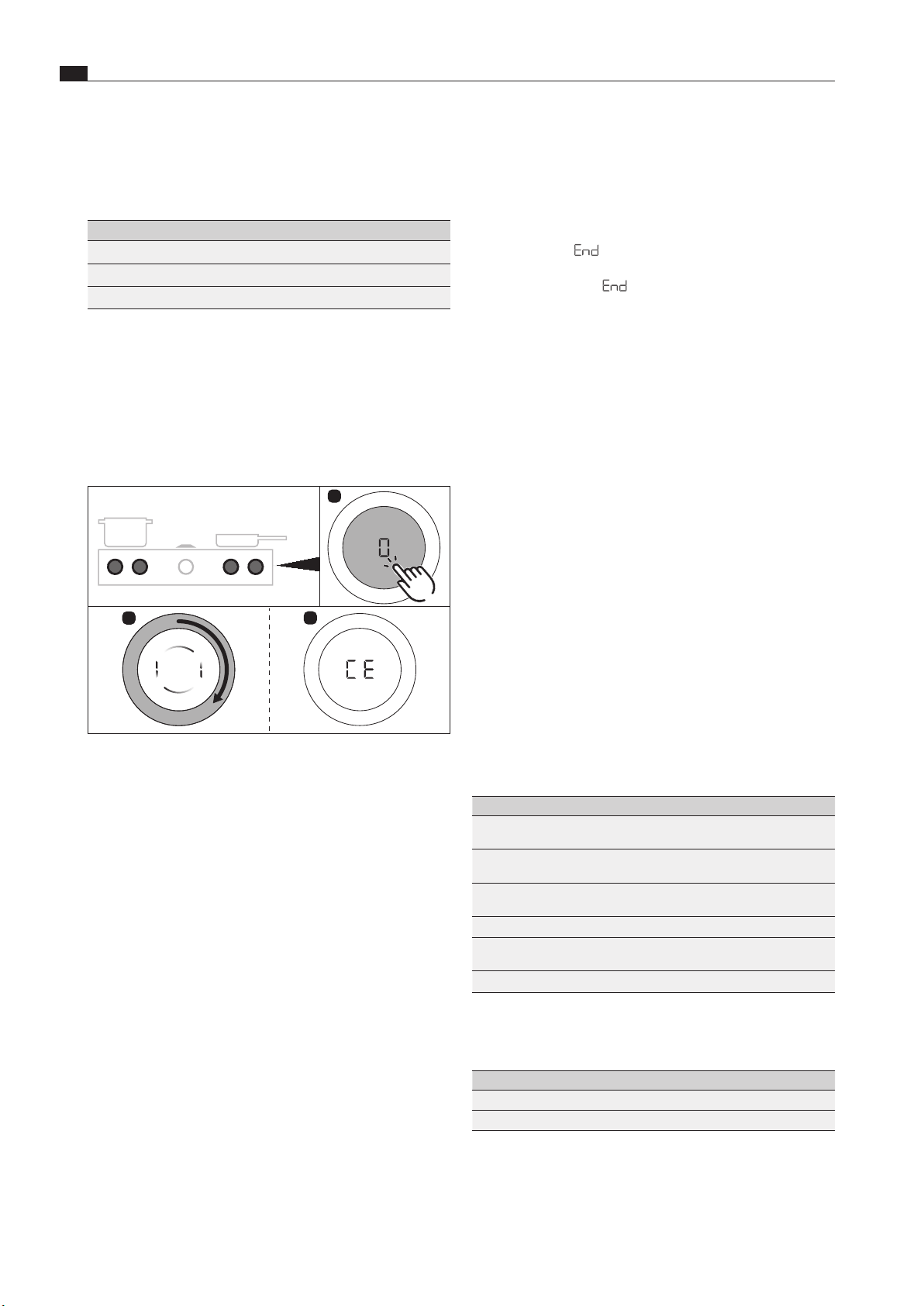
EN
30
Configuration menu
www.bora.com
6 Configuration menu
Closing the menu
i
When navigating the menu, after the last menu item there
is an option
End
to close the menu.
X
Turn the knob ring to
End
X
Tap to confirm the selection.
O
The menu is closed and the standard display appears.
i
If no settings are changed in a menu or submenu item for
2 minutes, the configuration menu is closed automatically
and the display goes out. The settings made are saved
automatically.
6.2 Initial operation
6.2.1 Gas configuration menu items
i
The burner nozzles, gas type, gas pressure and gas
characteristic curve may only be changed by a certified
engineer or BORA service technician. They also assume
responsibility for the proper gas installation and
commissioning.
i
Correct settings are important for the safe, problem-free
operation of the gas cooktop.
Menu item
CE
: GPU configuration
i
Under menu item
CE
(GPU) the minimum power of each
burner and gas type/pressure is regulated.
Setting Gas type and gas pressure
0
G20, 20 mbar
G25, 20 mbar
(Factory setting)
4
G30, 29 mbar
G30/G31, 37 mbar
5
G30, 50 mbar
G30/G31, 50 mbar
A
G20, 13mbar
b
G25, 25 mbar
G25.3, 25 mbar
C
G20, 25mbar
Tab. 6.2 Setting the gas type and gas pressure
Special settings for Australia and New Zealand:
Setting Gas type and gas pressure
1 G20, 10 mbar
9 G31, 27.5 mbar
Tab. 6.3 Setting the gas type and gas pressure (AU/NZ)
X
Select the correct setting.
Menu overview
Gas configuration menu
CE
GPU configuration
CF
Gas burner characteristic curves
Ch
GPU reset
Tab. 6.1 Gas conguration menu
6.1 How to use the menu
Calling up the menu
i
The menu can only be called up when the appliances are
switched on but are inactive (= power level 0).
5s
1
2
3
Fig. 6.38 Calling up the menu
X
Extralong press on a control knob on the gas cooktop
O
An animation appears (= prompt to turn)
X
Turn the ring on the control knob clockwise
O
The menu is called up and the first menu item is displayed.
Explanation of the menu item display (e.g. C23):
Number in middle segment = menu item (100% brightness)
Number in right-hand segment = current setting (50% brightness)
Selecting and confirming menu items
X
Turn the knob ring to the required menu item
(see “Menu overview”).
X
Tap to confirm.
Making, confirming and saving settings
X
Turn the knob ring to the desired setting (for setting options
see “Description of menu items”).
X
Tap to confirm the setting.
i
The system adopts and saves the settings made when
you exit the corresponding menu item or the menu itself.
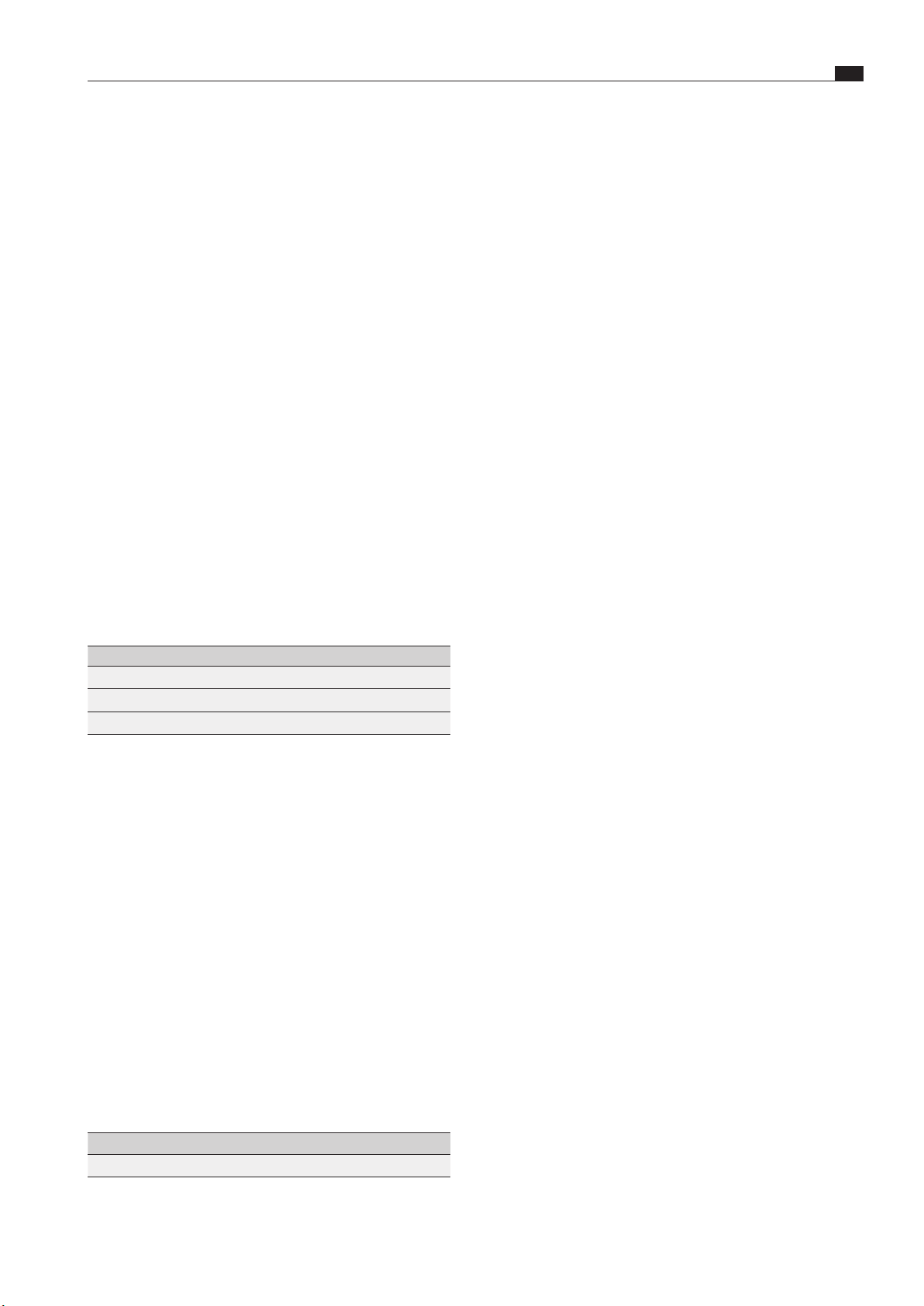
EN
31
Configuration menu
www.bora.com
Menu item
CF
: gas burner characteristic curves
The characteristic curves regulate the minimum gas burner
power values. The minimum power levels are adjusted using the
characteristic curves. Depending on the installation situation
and the influence of the cooktop extractor, if necessary, the
characteristic curve can be changed.
Characteristic curve A:
Characteristic curve A enables the fine tuning of the power
values, which can only be adjusted in the best-case scenario and
only in the case of natural gas (G20, G25, G25.3).
The best-case scenario is when:
O
no cooktop extractor is in operation; or
O
the cooktop, when using the cooktop extractor in exhaust air
mode, is used with sufficient ventilation; or
O
the cooktop, when using the cooktop extractor in recirculation
mode is used with a sufficient return flow aperture and the
cooktop extractor does not have a negative influence on the
gas flame.
Characteristic curve B:
Factory default characteristic curve with balanced adjustment of
the individual power levels.
Characteristic curve C:
Characteristic curve C increases the lower power levels and
should only be used in the event of a negative influence from the
cooktop extractor.
Setting Gas burner characteristic curves
0
Characteristic curve A
1
Characteristic curve B
(Factory setting)
2
Characteristic curve C
Tab. 6.4 Characteristic curves for the gas burner
X
Select the appropriate characteristic curve.
i
If the gas flame goes out, is excessively affected by the
extractor and/or the flame is not as it should be (e.g.
soot production, flame blowback, etc.), the characteristic
curve must be increased, as well as the ventilation
in exhaust air mode, if necessary, or the return flow
aperture in recirculation mode.
Menu item
Ch
: GPU reset
i
Menu item
Ch
(GPU reset) provides a reset function.
This reset function can be used in the case of faults and
errors and during initial operation if the gas cooktop does
not react (does not ignite).
i
The set values for the gas type, pressure and
characteristic curve remain unchanged and are not
affected by the reset.
Setting GPU reset
0
Resetting a locked GPU
Tab. 6.5 Resetting a locked GPU
X
Perform a reset if necessary.
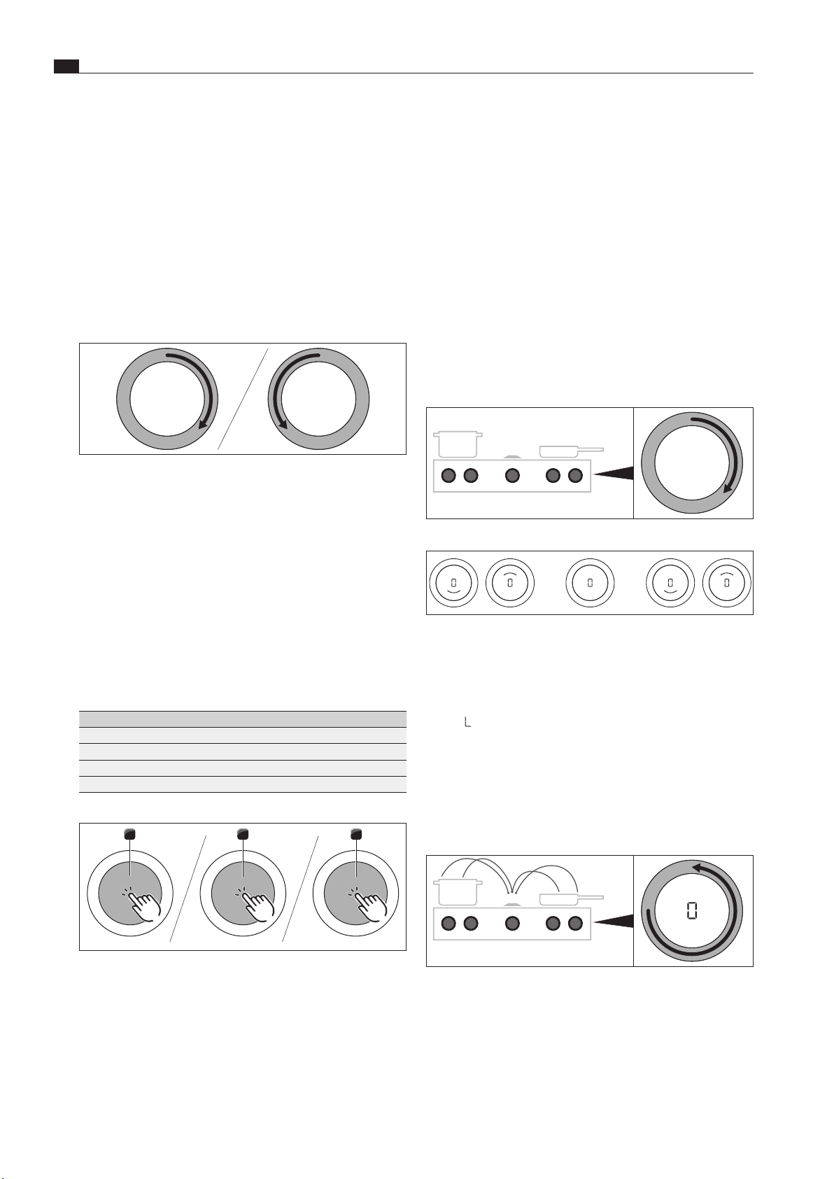
EN
32
Functions and operation
www.bora.com
7 Functions and operation
Use double-tap commands to:
O
activate the pause function
Use long-press commands to:
O
Deactivating the childproofing feature
Use extra-long-press commands to:
O
reset the filter service life
O
access the configuration menu
7.2 Switching the system on and off
Switching on
Fig. 7.3 Switching on the system
Fig. 7.4 Standard display after switching on
X
Turn a knob ring of your choice clockwise
O
The system is activated.
O
0
is displayed on all control knobs.
i
If
L
is displayed on all control knobs when the appliance
is switched on, the childproofing feature is active. It will
only be possible to operate the appliance when this has
been deactivated (see “Deactivating the childproofing
feature for a cooking session” or “Permanently
deactivating the childproofing feature”).
Switching off
Fig. 7.5 Switching the appliances off
X
Turn the knob ring anticlockwise to power level 0.
O
Any active additional functions will be deactivated and the
appliance will be switched off.
i
If all connected appliances are switched off (= power
level 0), the whole system is automatically switched off
after 10 seconds.
X
Observe all safety and warning information during operation
(see the “Safety” chapter).
7.1 Knob operation
Operating the knob ring
The ring on the control knob can be turned both clockwise and
anticlockwise. It can be turned as far as you wish; there is no
defined 0 position.
Fig. 7.1 Operating the knob ring
Turn it clockwise (to the right) to:
O
switch on
O
increase power level/value
O
navigate the menu
Turn it anticlockwise (to the left) to:
O
switch off
O
decrease power level/value
O
navigate the menu
Operating the touch surface
The touch surface of the control knob reacts to different touch
commands:
Command Contact Time
Tap brief touch <1s
Double tap 2 brief taps one after the other
Long press keep finger in place longer 2 – 4 s
Extra-long press keep finger in place longer 5 – 8 s
Tab. 7.1 Operating the touch surface
>2s >5s
1 2 3
Fig. 7.2 Diagram of the touch commands
[1] Tap command diagram
[2] Long press diagram
[3] Extra-long press diagram
Use tap commands to:
O
call up the function menu
O
confirm menu items/times/functions
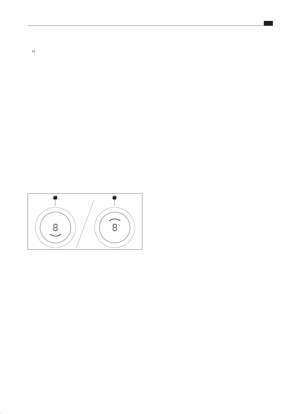
EN
33
Functions and operation
www.bora.com
i
As a result of use, some of the components of the gas
cooktop can become discoloured. This discolouration is
normal and does not have a negative effect on the gas
flame or the functioning of the cooktop.
i
When using the gas burner, you may hear gas escaping
from it. The burner flame turns orange as a result of
impurities on the burner and in the ambient air (dust).
These properties are normal and can occur independently
of one another.
i
In the event of smoke or fire while operating the gas
cooktop, turn off the gas supply and switch off the
appliance at the wall socket.
i
If you smell gas or have problems with the gas
installation, switch off the gas supply. Open the window
and ensure good ventilation.
X
The use of a gas cooker generates heat, moisture and
combustion products in the room in which it is installed.
Good ventilation in this room is particularly important when
the appliance is in use: natural ventilation openings must be
kept open or a mechanical ventilation device should be used.
Intensive use of the appliance for a long time may result in
a need for additional ventilation, e.g. opening a window, or
more effective ventilation, e.g. operation of the mechanical
ventilation device at a higher power level.
Correct use of the gas hob
i
Do not use the gas cooktop without cookware for
extended periods of time (>5min) with the cooktop
extractor switched on. This results in very high
temperatures and may damage the gas cooktop and air-
channelling components of the cooktop extractor.
i
The tips of the flames should remain under the base
of the pot. Protruding flame tips emit heat into the air
unnecessarily and can damage pan handles and air-
channelling components (cooktop extractor) and increase
the risk of burns. Furthermore, the outer part of the gas
flame is much hotter than the core.
i
Protect your hands when the appliance is hot by using
oven gloves or pot holders. Only use dry gloves or pot
holders. Wet or damp fabrics conduct heat more easily
and can cause steam burns. Ensure that these fabrics do
not get too close to the flames. Do not use oversized pot
holders, tea towels or similar.
i
Grease splashes and other flammable (food) residues
on the cooktop can catch fire. Remove them as soon as
possible.
X
Do not put cookware with an uneven base on the pan support.
X
Never heat empty cookware.
X
Always place the cookware on the pan support provided.
Cookware must not be placed directly on the burner.
X
Do not use roasters, pans or stone grills that are so large that
they cover several burners. The resulting heat accumulation
can damage the cooktop.
The cooktop was switched on
O
H
is shown in the control knob display for previously active
and still hot cooking zones (residual heat indicator).
O
If there is no longer any residual heat, the display will switch
off after 10 seconds.
7.3 Operating the cooktops
i
The full range of functions is only available for BORA
Professional 3.0 system cooktops in combination with
the corresponding cooktop extractors PKA3/PKA3AB and
PKAS3/PKAS3AB.
i
Clean the cooking zones before using the cooktop for the
first time (see the Cleaning chapter).
7.3.1 General operating instructions for cooktops
Cooktops are operated with 2 control knobs.
There are 9 power levels, an optional power setting and various
functions available for each cooking zone.
Each cooking zone has its own control knob. The front cooking
zone is controlled using the left-hand knob and the rear cooking
zone with the right-hand knob.
1 2
Fig. 7.6 Cooking zone indicator
[1] active front cooking zone
[2] active rear cooking zone
7.3.2 Special operating instructions for gas
cooktop PKG3
i
When operating the cooktop for the first time or after
a prolonged period without use or when the liquid gas
bottles have been changed, it is possible that the burner
may not ignite. This may be due to air in the gas pipe
or the electronic gas regulator may need recalibrating.
Follow the initial operation instructions (see the “Initial
operation” chapter).
i
Due to the use of enamelled cast iron parts, slight colour
variations and irregularities are common. Furthermore,
flash rust may appear at the support points, which can
be easily removed with a damp cloth. These spots are
normal and are not considered an impairment.
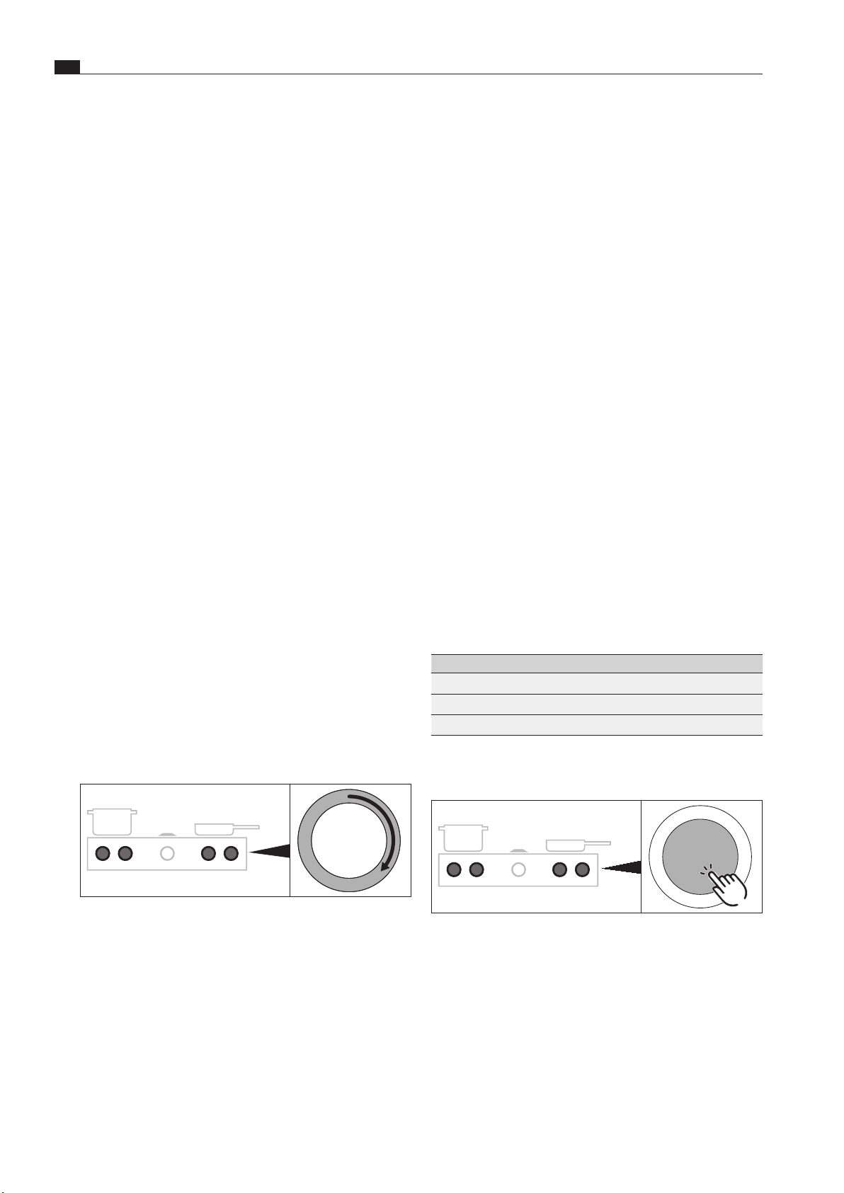
EN
34
Functions and operation
www.bora.com
X
Ensure that the burner parts and pan supports are positioned
correctly.
X
Do not switch the gas cooktop on until all burner parts are
correctly assembled.
X
Ensure that the burner flame does not protrude from under
the base of the cookware and rise up the outside of the pot.
X
Do not keep any highly flammable objects near the cooktop.
For maximum performance with minimum gas
consumption, we recommend that you:
X
use cookware with a base that covers the flame entirely so
that this does not burn beyond the base;
X
use suitable pans on each gas burner;
X
position the cookware centrally on the gas hob;
X
set the gas burner to the lowest power level (small flame)
once the pan contents are simmering;
X
adjust the power level of the cooktop extractor to the power
level of the gas cooktop.
Using the gas cooktop together with the cooktop
extractor
If the gas cooktop is used together with a cooktop extractor, the
airflow of the extractor can affect the gas flame.
X
Avoid using a high power level on the cooktop extractor when
the gas cooktop is set to a low power level.
X
If necessary, reduce the power level on the cooktop extractor
when you turn on the gas cooktop.
X
Do not use the gas cooktop without cookware. The gas flame
is protected from the airflow of the cooktop extractor by the
geometry of the pan supports and the cookware.
i
Flames can set fire to or damage the grease filter in the
cooktop extractor and the air-channelling components.
Never flambé food when using a cooktop extractor.
7.3.3 Setting cooking zone power levels
The power levels are controlled by turning the knob ring to the
desired power level (electronic power adjustment).
Fig. 7.7 Setting cooking zone power levels
O
The selected power level is shown in the power display on the
control knob that has been touched.
O
Upon touching a control knob, the selected power level is
shown in the display.
Increasing the power level
X
Turn the knob ring clockwise
Reducing the power level
X
Turn the knob ring anticlockwise
7.3.4 Cooktop power setting
When the power setting is activated, maximum cooking zone
power is available for a predefined time.
i
Never heat up oil, fat and the like on this power setting.
The bottom of the pan can overheat due to the high
power output.
Activating the power setting for a cooking zone
X
Turn the knob ring clockwise to power setting
P
.
i
After 10 minutes, the power setting is automatically
switched back to power level 9.
i
After 20 minutes, the power setting is automatically
switched back to power level 9.
Deactivating the power setting early
O
Setting another power level for the cooking zone with the
power setting active
7.4 Function menu
i
Every appliance offers different additional functions.
These can be selected and activated via a function menu.
Only the functions available for each type of appliance
are shown in the corresponding function menu.
Function menu on gas cooktop PKG3
A total of 3 additional functions are available on gas cooktops:
Menu item Description
1 v
Heat retention function (3 levels)
2 t
Timer function (automatic cut-off)
3 A
Automatic heat up function
Tab. 7.2 Function menu on gas cooktop PKG3
Calling up the function menu
Fig. 7.8 Accessing a cooktop function menu
X
Touch the cooktop control knob
O
The function menu is opened.
O
The first menu item is shown in the control knob display.
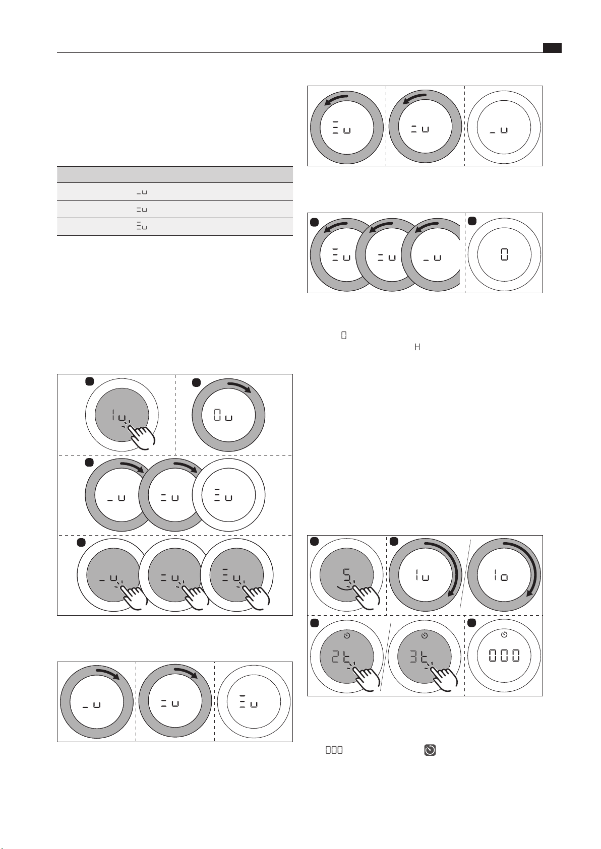
EN
35
Functions and operation
www.bora.com
7.4.1 Variable heat retention function
The 3 heat retention levels enable cooked foods to be kept warm
at a constant temperature.
O
The maximum duration of the heat retention function is limited
to 8 hours.
Heat retention level
Symbol Temperature Use
1
,
v
42°C Melting chocolate
2
:
v
74°C Keeping food warm
#
3
*
v
94°C Simmering
Tab. 7.3 Heat retention levels
i
In practice the temperatures of the heat retention
levels may vary slightly as they are influenced by the
cookware, the amount of food and the different heating
technologies. The temperatures can also vary due to the
influence of the cooktop extractor.
Activating the heat retention function
X
Open the cooktop function menu.
X
Enter the following settings:
1
2
3
4
Fig. 7.9 Activating the heat retention function
Increasing or reducing the active heat retention level
Fig. 7.10 Increasing the active heat retention level
Fig. 7.11 Reducing the active heat retention level
Deactivating the heat retention function
1
2
Fig. 7.12 Deactivating the heat retention function
O
The cooking zone is deactivated and the control knob display
shows
0
.
O
The residual heat indicator
H
appears in the control knob
display if necessary.
7.4.2 Timer function/automatic cut-off
When a cooking zone is in operation, the automatic cut-off on
the timer function automatically switches it off once a preset
time has lapsed.
i
You can set a time range of between 1 and 120 minutes
for the timer functions.
Activating cooking zone timers
X
Open the cooktop function menu.
X
Do the following:
1
2
3
4
Fig. 7.13 Activating cooking zone timers
O
The timer is activated for the chosen cooking zone.
O
The control knob display shows the time to be set beginning
at
0
0
0
and the timer symbol .
O
If no time is set within 4 seconds, the timer is deactivated.
The control knob display goes back to the current cooking
session.
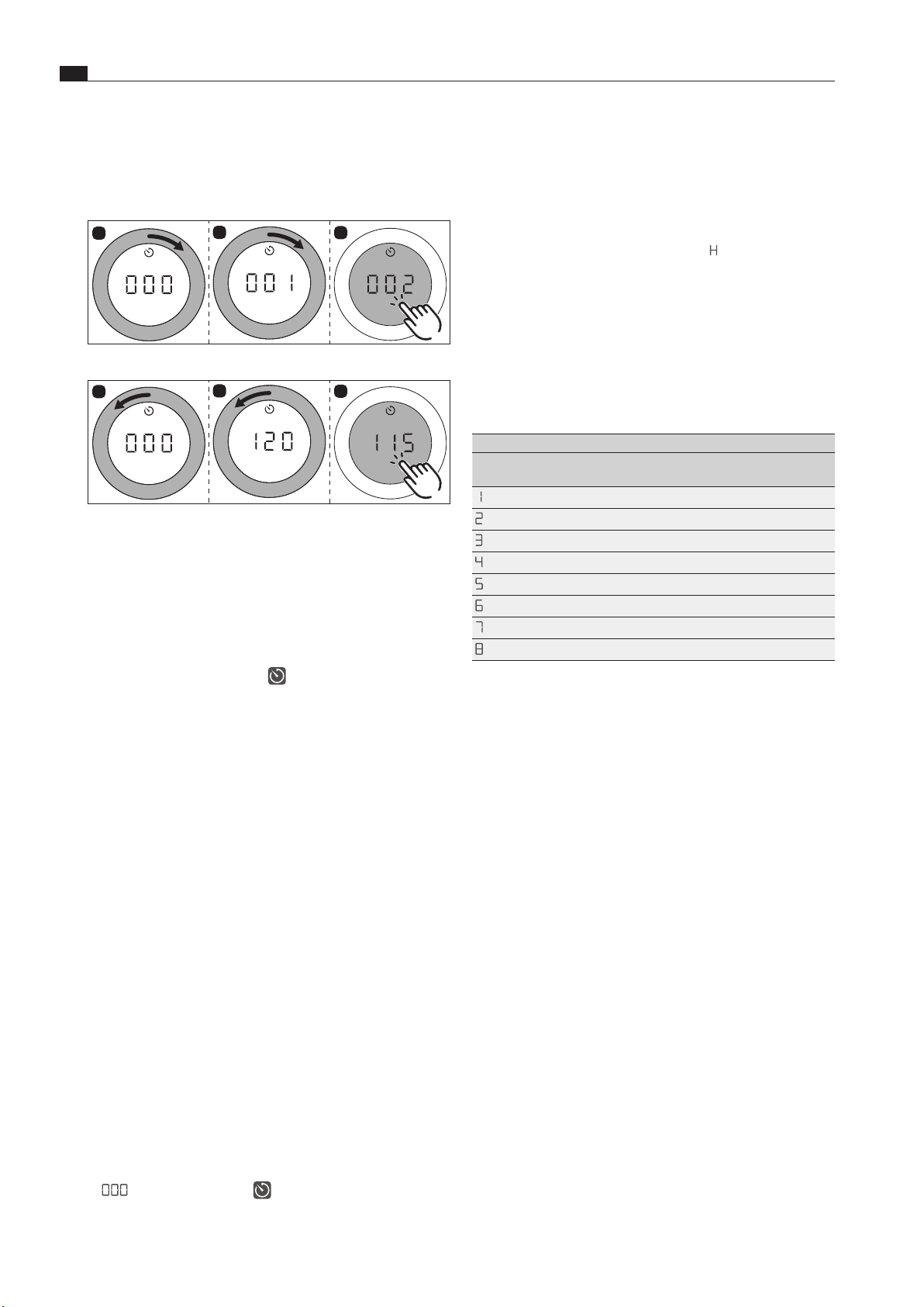
EN
36
Functions and operation
www.bora.com
Setting the time and starting the timer
i
Turning clockwise increases the time (starting at
0 minutes). Turning anticlockwise reduces the time.
5
6
7
Fig. 7.14 Turning the knob ring clockwise
5
6
7
Fig. 7.15 Turning the knob ring anticlockwise
O
In the range from 0 to 20 minutes, the time reduces/
increases in both directions by one minute at a time, while the
increments are 5 minutes for the rest of the range.
O
After confirming with a touch command, an acoustic signal
is heard, the cooking zone timer is activated and the set time
starts to count down.
O
The control knob display changes to the current cooking
session and the timer symbol
is displayed.
O
The set power level and the remaining time are shown
alternately in the control knob display for 3 seconds.
O
Once the remaining time is less than 2 minutes, only the
remaining time is displayed.
O
Once the remaining time is less than 5 seconds, the remaining
time flashes.
Changing active timers
X
Repeat the steps for cooking zones with an active timer (see
“Activating cooking zone timers”).
X
Change the set time and restart the timer.
Switching the timer off early
If the cooking session is to be continued:
X
open the cooktop function menu;
X
select the menu item “timer function (automatic cut-off)”;
X
decrease the set time to
000
and confirm the entry.
O
The timer is deactivated early and an acoustic signal is heard.
O
Active cooking sessions are resumed unchanged.
If the cooking session is to be ended:
X
turn the knob ring to power level
0
O
An acoustic signal sounds and the cooking zone is switched off.
Time lapsed
O
The cooking zone switches off automatically.
O
An acoustic signal is heard.
O
0
0
0
and the timer symbol can be seen flashing in the
control knob display.
O
After 5 seconds the acoustic signal and the flashing display
are automatically deactivated.
i
The flashing display and acoustic signal can be stopped
early with a touch command on the control knob.
O
If necessary, the residual heat indicator
H
is then displayed.
7.4.3 Automatic heat up function
When the automatic heat up function is activated, the cooking
zone works at full power for a certain time and is then
automatically reset to the previously set level.
The system automatically determines the heating time
depending on the power level set.
PKG3
Power level (continuous cooking
level)
Cooking times in min:sec
1
00:40
2
01:00
3
02:00
4
03:00
5
04:20
6
07:00
7
02:00
8
03:00
Tab. 7.4 Overview of heating times
i
If the cooking zone power level is increased while the
automatic heat up function is active, the automatic heat
up function remains active. The heating time is adjusted
accordingly.
i
If the cooking zone power level is decreased while the
automatic heat up function is active, the automatic heat
up function is deactivated.
Requirement for the automatic heat up function:
O
cooking session with a power level between 1 and 8.
Activating the automatic heat up function
X
Open the cooktop function menu.
X
Do the following:
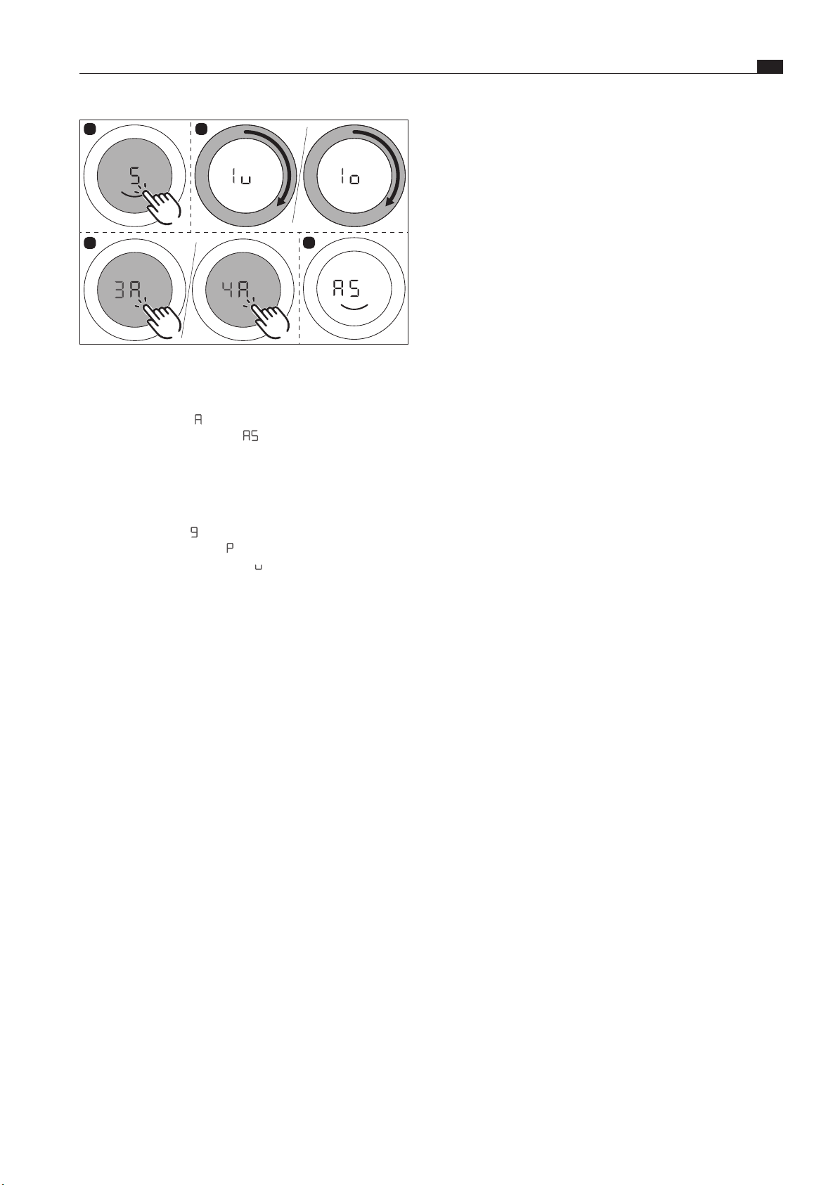
EN
37
Functions and operation
www.bora.com
1
2
3
4
Fig. 7.16 Activating the automatic heat up function
O
An acoustic signal is heard, the automatic heat up function is
activated and the corresponding timer counts down.
O
The heat-up symbol
A
and the set power level are shown in
the control knob display (e.g.
A
5
).
Deactivating the automatic heat up function early
The activated automatic heat up function will end prematurely if
you
X
reduce the power level (continuous cooking level);
X
set the power level
9
;
X
activate the power setting
ßp
;
X
activate the heat retention level
v
;
X
switch off the cooktop.
Time lapsed
O
When the heat up time has lapsed, the previously set
continuous cooking level will be activated.
O
An acoustic signal is heard.
O
The heat up symbol will no longer be displayed

EN
38
Cleaning and maintenance
www.bora.com
8 Cleaning and maintenance
8.2 Cleaning the cooktops
8.2.1 Cleaning glass ceramic cooktops
X
Make sure that the cooktop is switched off (see the Operation
chapter).
X
Make sure the gas supply is interrupted and switched off.
X
Wait until all cooking zones are cold.
X
Remove all coarse dirt and food residues from the cooktop
using a glass ceramic scraper.
X
Apply the cleaning agent to the cold cooktop.
X
Spread the cleaning agent using kitchen roll or a clean cloth.
X
Wipe the cooktop clean with a damp cloth.
X
Dry the cooktop with a clean cloth.
If the cooktop is hot:
X
remove stubborn residues of plastic, aluminium foil, sugar or
sweet dishes from the hot cooking zone immediately using a
glass ceramic scraper to prevent burning.
Heavy soiling
X
Remove heavy soiling and marks (limescale marks, mother-
of-pearl-like shiny marks) using cleaning products while the
cooktop is still warm.
X
Wipe off any food that boils over with a damp cloth.
X
Remove any remaining dirt with the glass ceramic scraper.
X
Always remove any seeds, crumbs or similar that fall onto the
cooktop during cooking immediately to prevent the surface
getting scratched.
Any changes in colour or glossy spots do not mean that the
cooktop is damaged. They do not affect the functionality of the
cooktop or the stability of the glass ceramic panel.
Changes in the colour of the cooktop are the result of residues
which have not been removed and have burnt on.
Glossy spots are the result of wear by the pan base, especially
if aluminium-based cookware or unsuitable cleaning agents are
used. These are difficult to remove.
i
Due to the use of enamelled cast iron parts, slight colour
variations and irregularities are common. Furthermore,
flash rust may appear at the support points, which can
be easily removed with a damp cloth. These spots are
normal and do not constitute an impairment
X
Observe all safety and warning information (see the Safety
chapter).
X
Follow the enclosed manufacturer’s information.
X
When conducting scheduled cleaning and maintenance,
ensure that the cooktop and cooktop extractor are fully
switched off and cooled so as to prevent injury (see the
Operation chapter).
O
Regular cleaning and maintenance ensures long service life of
the product and optimal function.
X
Adhere to the following cleaning and maintenance cycles:
Component Cleaning cycle
Control knob:
Knob ring/knob
housing
Immediately after every soiling
Gas cooktop:
Cooktop Clean well immediately after soiling, using
conventional detergents
Pan support
Gas burner
Tab. 8.1 Cleaning cycles
8.1 Cleaning agents
i
Due to the use of aggressive cleaning agents and
abrasion caused by the pot bases the surface will
become damaged and dark stains will occur.
X
Never use steam cleaners, abrasive sponges, scouring pads or
chemically aggressive cleaning agents (e.g. oven cleaner spray).
X
Make sure that the cleaning agent does not contain any sand,
soda, acids, lyes or chloride.
Cleaning products for glass ceramic cooktops
To clean the cooktop, you need a special glass ceramic scraper
and suitable cleaning agents.
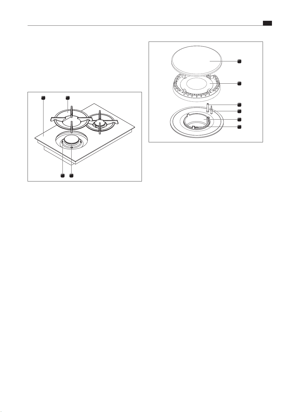
EN
39
Cleaning and maintenance
www.bora.com
1
2
3
4
5
6
Fig. 8.2 Gas burner structure
[1] Burner cap
[2] Burner head
[3] Electric igniter
[4] Safety thermocouple
[5] Burner housing
[6] Gas burner nozzle
O
Do not start cleaning until the gas burner has returned to
normal temperature after use.
O
The burner parts are not suitable for cleaning in the
dishwasher. Clean the burner parts by hand only.
O
Only clean with normal hot water to rinse and a conventional
washing-up liquid, using a soft sponge or a normal dishcloth.
O
Never scratch or scrape cooking residues off.
X
Remove the pan support.
X
Remove the burner cap [1] from the burner head [2].
X
Remove the burner head [2] from the gas outlet
X
Clean the parts of the burner.
X
Clean all of the flame outlet openings with a non-metallic
brush.
X
Wipe the fixed parts of the burner with a damp cloth.
X
Wipe the igniter electrode [3] and the thermocouple [4]
carefully with a well-wrung-out cloth.
O
The igniter electrode must not get wet, otherwise the ignition
spark will not light.
X
Finally, dry the pan supports carefully with a clean cloth.
O
Before reassembling the flame openings, burner heads and
burner caps must be completely dry.
X
Put the burner parts back together again.
X
Position the burner head [2] correctly on the gas outlet.
X
Ensure that the safety thermocouple [4] and the electric
igniter [3] are positioned in the correct opening.
X
Position the burner cap [1] so that it fits perfectly, sitting
straight on the burner head [2].
O
If burner parts are not positioned correctly, the electric igniter
will not work.
X
Place the pan support straight on the gas burner so it fits
perfectly.
X
Put the gas burner into operation (see the Operation chapter).
8.2.2 Cleaning the pan supports
i
The surface of the pan support will become duller with
the passing of time. This is quite normal and does not
mean that the material is damaged.
i
The pan supports must be washed by hand every time
they become dirty.
3
21
4
Fig. 8.1 Gas burner structure
[1] Gas cooktop
[2] Pan support
[3] Gas burner
[4] Positioning aid
X
Remove the pan support [2].
O
Pan supports can only be cleaned by hand.
Manual cleaning
X
Use a cleaner and degreaser in one.
X
Rinse the pan supports with hot water.
X
Clean the pan supports with a soft brush.
X
Rinse the pan supports well after cleaning.
X
Dry the pan supports carefully with a clean cloth.
i
In the case of particularly stubborn or burned-on dirt,
the pan support can be briefly soaked in warm water
with washing-up liquid. Any limescale marks can be more
easily removed with diluted vinegar.
8.2.3 Cleaning the gas burner parts
i
The surface of the burner cap will become duller with the
passing of time. This is quite normal and does not mean
that the material is damaged.
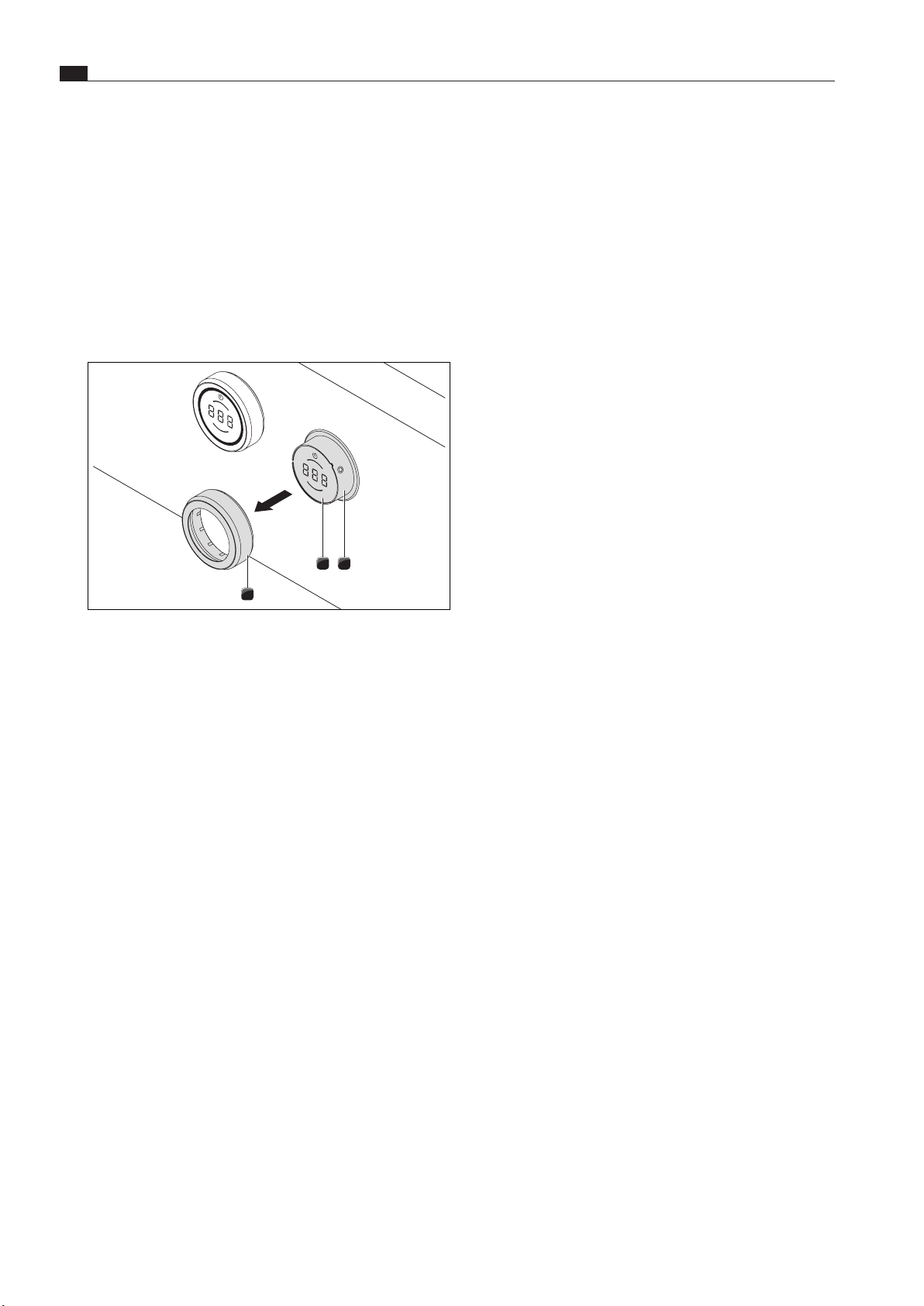
EN
40
Cleaning and maintenance
www.bora.com
8.3 Looking after your cooktops
X
Never use a cooktop as a work or storage surface.
X
Do not push or pull cookware over the cooktop.
X
Always lift pots and pans.
X
Keep the cooktop clean.
X
Remove any dirt immediately.
X
Only use suitable cookware on the appliance (see the
Appliance description chapter).
8.4 Cleaning the control knobs
12
3
Fig. 8.3 Pull out the knob ring
[1] Knob housing
[2] Touch surface
[3] Knob ring
Cleaning the knob ring
The knob ring can only be cleaned by hand.
X
Remove the knob ring from the knob housing.
X
Use a cleaner and degreaser in one.
X
Rinse the knob ring with hot water.
X
Clean the knob ring with a soft brush.
X
Rinse the knob ring well after cleaning.
X
Dry the knob ring carefully.
X
Place the dry knob ring back on the knob housing.
Cleaning the touch surface and the knob housing
X
Remove the knob ring.
X
Clean the touch surface and the knob housing with a soft,
damp cloth.
X
Dry the touch surface and the knob housing carefully.
X
Place the knob ring on the knob housing.
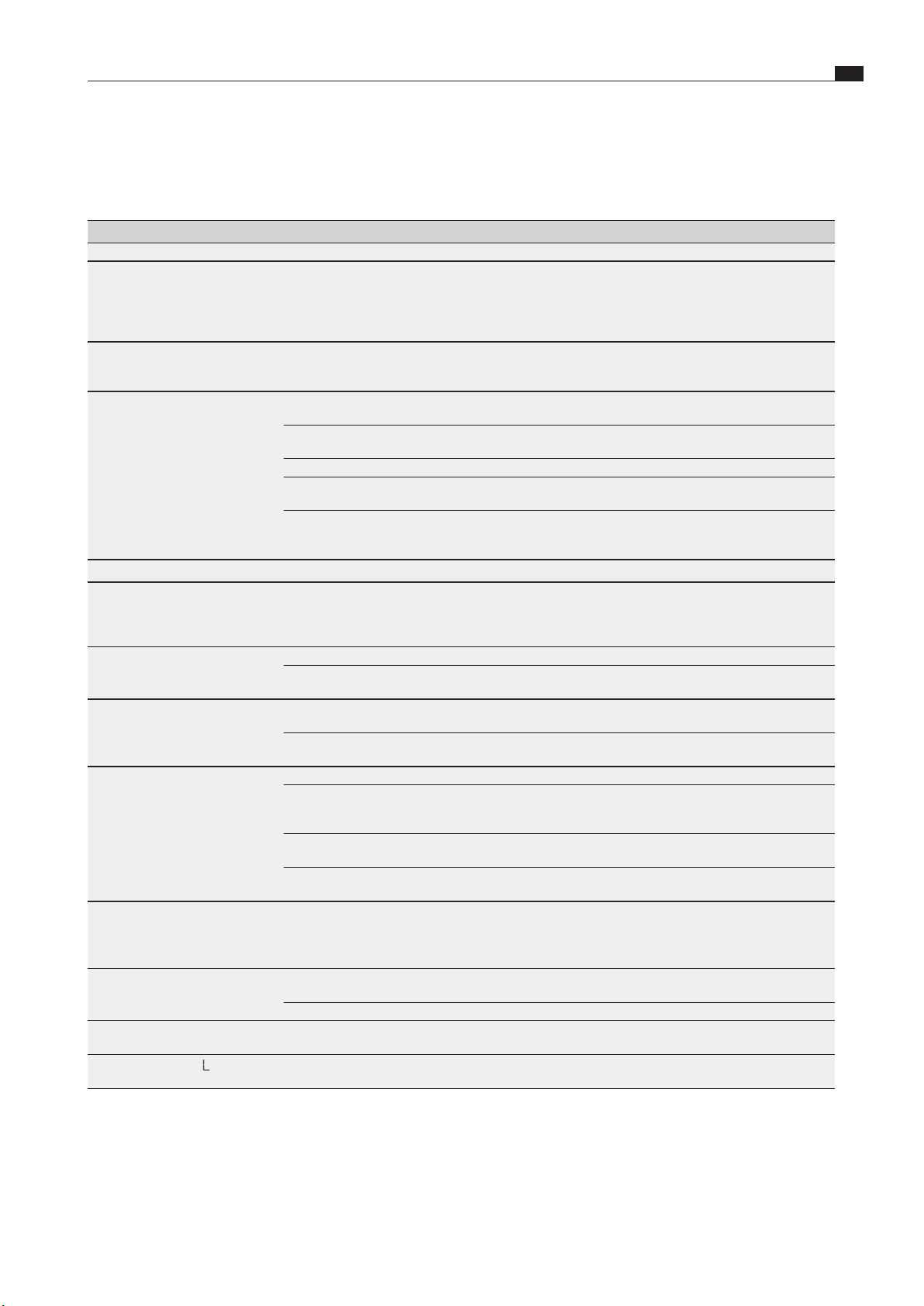
EN
41
Troubleshooting
www.bora.com
9 Troubleshooting
X
Observe all safety and warning information (see the “Safety” chapter).
Operating situation Cause Remedy
When operating for the first time, after a prolonged period without use or after changing the gas bottle:
burner doesn’t ignite. There is air in the gas pipe. Repeat the ignition process several times if
necessary. This can be done using the touch-
operated area of the control knob if the power level
is flashing or by turning the control knob to power
level 0, then setting the power level.
Gas cooktop does not react
(servomotors do not calibrate and
no ignition).
There is a communication error between the
operating unit and the cooktop (e.g. in the event of
a power cut).
Perform a reset (see “Gas configuration menu”).
The gas burner cannot be ignited
electrically.
The gas burners are damp. Dry the gas burner parts (see the “Cleaning”
chapter).
The gas burner heads and/or the gas burner cover
are not correctly positioned.
Position the gas burner parts correctly (see the
“Cleaning” chapter).
The electric igniter and/or thermocouple are dirty. Remove the dirt (see the “Cleaning” chapter).
Dirt in the gas burner head. Clean the gas burner parts (see the “Cleaning”
chapter).
Ignition failed. Power display flashes. Repeat the ignition process by setting a power
level. If the power level is flashing, this can be done
using the touch-operated area of the control knob.
During normal operation:
you notice the smell of gas. A leakage point in the gas supply line. Switch off the gas supply and immediately
extinguish all open flames. Contact a gas engineer.
Ensure that all connections are tight (see the “Gas
installation” chapter).
No gas is coming out of the gas
burners.
The gas supply is closed. Open the gas supply (see the “Operation” chapter).
The gas bottle is empty. Exchange the empty gas bottle for a full gas bottle
of the correct gas type.
The gas flame goes out after
ignition. The gas flame goes out
during operation.
The gas flame is uneven.
The gas burner parts (burner heads and/or th
e
gas burner cover) are not correctly positioned.
Position the gas burner parts correctly (see the
“Cleaning” chapter).
Dirt in the gas outlet openings on the gas burner
head.
Clean the gas burner parts (see the “Cleaning”
chapter).
The cooktop cannot be switched
on.
Knob ring missing. Slot the knob ring onto the control knob.
The fuse or automatic circuit breaker of the
electrical wiring system in the apartment and/or
house is defective.
Replace the fuse. Switch the automatic circuit
breaker back on.
The fuse or the automatic circuit breaker trips
several times.
Contact the BORA Service Team.
The power supply is disconnected. Have a specialist electrician inspect the power
supply.
Odours and vapours are formed
when operating the new cooktop.
This is normal with brand new appliances. Wait a few operating hours.
If odours continue to form, contact the BORA
Service Team.
A cooking zone or the entire
cooktop switches off automatically.
A cooking zone has been in operation too long. Put the cooking zone back into operation (see the
“Operation” chapter).
The overheating protection has tripped. (see the “Appliance description” chapter).
The power setting is automatically
shut off prematurely.
The overheating protection has tripped. (see the “Appliance description” chapter).
Control knob display
L
.
The childproofing feature is activated. Switch off the childproofing feature (see the
“Operation” chapter).
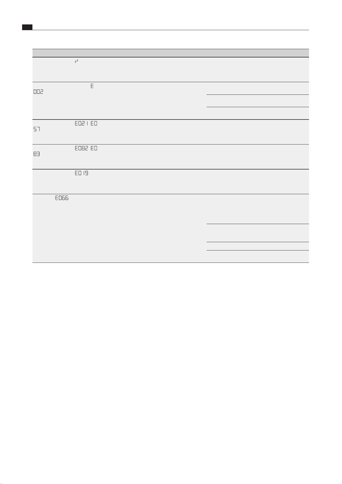
EN
42
Troubleshooting
www.bora.com
Operating situation Cause Remedy
Control knob display
/
.
Continuous operation (8 s) of the control knob or
control knob dirty.
Take your finger off the control knob or clean the
knob.
Control knob display
E
0
0
1
,
E
0
0
2
.
Error when the software is running. Perform a reset (configuration Ch) (see the
“Installation” chapter).
Disconnect the device from the mains for at least
1 min. and restart it.
Contact the BORA Service Team.
Control knob display
E
0
2
1
,
E
0
5
7
.
Temperature too high. Allow the cooktop to cool.
Control knob display
E
0
8
2
,
E
0
8
3
.
Check the connection to the temperature sensor. Replace temperature sensor.
Call the BORA Service Team.
Control knob display
E
0
1
9
.
Error in the touch surface values. Perform touch command.
Call the BORA Service Team.
Error code
E
0
6
6
.
Gas supply interrupted and/or no flame detected.
The gas bottle is empty.
Repeat the ignition process several times if
necessary. This can be done with a touch
command on the control knob when the power
level is flashing or by turning the control knob to
power level 0 and then setting the power level.
Confirm error E_066 and try to ignite it again. (The
gas pipe needs a certain amount of time to fill after
installation).
Check the gas or mains connection.
Contact the BORA Service Team.
Tab. 9.1 Resolving a fault
X
After troubleshooting try again and check that the problem has been solved.
X
With all faults, try restarting the system.
X
As a last resort, briefly disconnect the power supply.
i
During or after an interruption to the power supply, the cooktops may still be hot. In the case of cooktops PKCH3, PKCB3 and
PKG3, after an interruption to the power supply the residual heat is not displayed, even if they were previously in operation
and the cooking zones are still hot.
X
Should faults arise frequently, contact the BORA Service Team (see the “Warranty, service, spare parts and accessories” chapter)
and specify the error number displayed and the appliance type (see the “Identification plates” chapter).
EN
43
Decommissioning, disassembly and disposal
www.bora.com
10 Decommissioning, disassembly and disposal
10.3 Environmentally-friendly
disposal
Disposal of transport packaging
i
The packaging protects the device from damage in
transport. The packaging materials have been selected
from environmental and disposal perspectives and are
therefore recyclable.
Returning the packaging to the materials cycle saves resources
and reduces waste volumes. Your specialist supplier will take the
packaging back.
X
Give the packaging to your specialist supplier
or
X
Dispose of the packaging properly in line with local
regulations.
Disposal of old appliance
Electrical devices marked with this label
may not be disposed of in domestic waste
at the end of their service life. They must
be disposed of at a collection point for
the recycling of old electrical or electronic
devices. You can find information from your
city or district council.
Many electrical and electronic devices still contain valuable
materials. But they also contain damaging materials which
were necessary for them to function properly and safely. These
can damage human health or the environment if disposed of
improperly or incorrectly handled.
X
Never put your old appliance in domestic waste.
X
Take the old appliance to a regional collection point for return
and recycling electrical and electronic components and other
materials.
X
Observe all safety and warning information
(see the Safety section).
X
Follow the enclosed manufacturer’s information.
10.1 Decommissioning
Decommissioning is understood as final shutdown and
disassembly. Following decommissioning, the device can either
be installed into other units, sold on privately or disposed of.
i
Electricity and gas connections may only be disconnected
by qualified specialists.
X
To decommission, switch the device off
(see Operation section)
X
Disconnect the device from the power supply.
X
Disconnect the device from the gas supply.
10.2 Disassembly
For removal, the device must be accessible for disassembly and
disconnected from the power supply.
For gas devices, make sure the gas connection is disconnected.
X
Undo the appliance fixture.
X
Remove the silicone joints.
X
Remove the device from the worktop by lifting it upwards.
X
Remove any other accessories.
X
Dispose of the old device and any contaminated accessories
as described under “ Environmentally-friendly disposal”.

EN
44
Warranty, technical service, spare parts, accessories
www.bora.com
accessories
X
Observe all safety and warning information (see the Safety
chapter).
11.1 BORA manufacturer’s warranty
BORA provides its end customers with a 2-year manufacturer’s
warranty for its products. The end customer is entitled to this
warranty in addition to the statutory claims for defects against
the sellers of our products.
The manufacturer’s warranty applies to all BORA products sold
by authorised BORA dealers or BORA-trained salespeople within
the European Union, with the exception of products labelled by
BORA as Universal products or accessories.
The manufacturer’s warranty starts as soon as the BORA
product is handed over to the end customer by an authorised
BORA dealer and is valid for 2 years. By registering on www.
bora.com/registration the end customer has the possibility of
extending the manufacturer’s warranty.
The manufacturer’s warranty requires expert (in accordance with
the valid BORA ventilation handbook and operating instructions
at the time of installation) installation of the BORA products by
an authorised BORA dealer. During use, the end customer is to
adhere to the specifications and instructions in the operating
manual.
In order to file a warranty claim, the end customer is to notify
their dealer or BORA of the fault and must present the receipt.
Alternatively, the end customer can provide proof of purchase by
registering on www.bora.com.
BORA guarantees that all BORA products are free from material
and product defects. The defect must exist prior to delivery of
the product to the end customer. In the event that a warranty
claim is filed, the warranty shall not commence anew.
BORA will correct defects in BORA products at its own discretion
by repairing or replacing the product. All costs for the correction
of defects under the manufacturer’s warranty shall be assumed
by BORA.
Expressly not covered by the BORA manufacturer’s warranty are:
O
BORA products that were not sold by authorised BORA dealers
or from BORA-trained salespeople.
O
Damage caused by non-adherence to the operating
instructions (including product care and cleaning) This
represents improper use.
O
Damage caused by normal use, e.g. traces of usage on the
cooktop
O
Damage caused by external influences (such as transport
damage, ingress of condensation, damage caused by the
elements such as a lightning strike)
O
Damage caused by repairs or attempts to repair not made by
BORA or persons authorised by BORA
O
Damage to the glass ceramic
O
Voltage fluctuations
O
Secondary damage or claims for damages beyond the defect
O
Damage to plastic parts
11 Warranty, technical service, spare parts,
Legal claims, such as particularly statutory claims for defects or
product liability are not limited by the warranty.
If a defect is not covered by the manufacturer’s warranty, the
end customer can employ the services of the BORA technical
service, however, they must cover the costs themselves.
The laws of the Federal Republic of Germany apply to these
warranty conditions.
You can contact us by:
O
Telephone: +49 800 7890 0987 Monday to Thursday from
08:00-18:00 and Friday from 08:00-17:00
O
Email: [email protected]
11.2 Service
BORA Service:
see reverse side of operating and assembly instructions
+800 7890 0987
X
In the case of faults you cannot fix yourself, contact your
BORA specialist supplier or the BORA Service Team.
The BORA Service Team will require the type designation and
serial number of your device
(FD number).
Both pieces of information can be found on the nameplate on
the back of the instructions and on the appliance base.
11.3 Spare parts
X
Only use original spare parts for repairs.
X
Repairs may only be carried out by the BORA Service Team.
i
Spare parts can be obtained from your BORA dealer, the
BORA online service website at www.bora.com/service
or by calling the service number provided.
11.4 Accessories
O
BORA Pro knob ring PKR3
O
BORA Pro knob ring All Black PKR3AB
Special accessory for glass ceramic cooktops:
O
BORA Glass ceramic scraper UGS
Special accessory for PKG3:
O
BORA gas nozzle set natural gas G25/25 mbar PKGDS2525
O
BORA gas nozzle set natural gas G20/13 mbar PKGDS2013
O
BORA gas nozzle set natural gas G20/20 mbar PKGDS2020
O
BORA gas nozzle set natural gas G25/20 mbar PKGDS2520
O
BORA gas nozzle set natural gas G20/25 mbar PKGDS2025
O
BORA gas nozzle set liquid gas G30/G31 50 mbar
PKGDS3050
O
BORA gas nozzle set liquid gas G30/G31 28-30 mbar
PKGDS3028
O
BORA burner set PKGBS
O
BORA pan support small PKGTK
O
BORA pan support big PKGTG

EN
45
Notes
www.bora.com
12 Notes

EN
46
Notes
www.bora.com

EN
47
Notes
www.bora.com

+800 7890 0987
Nameplate:
(please affix)
Operating and installation instructions: Original Translation
Manufacturer: BORA Vertriebs GmbH & Co KG
The distribution and duplication of this document, as well as the use and
disclosure of its contents are prohibited unless expressly authorised.
These operating and installation instructions have been drawn up with the greatest of care. But it cannot be ruled out that subsequent technical modifications
have not yet been incorporated or the relevant content has not yet been adapted. Please accept our apologies in this eventuality. An updated version can be
requested from the BORA Service Team. Subject to printing errors and mistakes.
© BORA Vertriebs GmbH & Co KG All rights reserved.
AU
NZ
BORA APAC Pty Ltd
100 Victoria Road
Drummoyne NSW 2047
Australien
T +61 2 9719 2350
F +61 2 8076 3514
www.bora-australia.com.au
D
BORA Lüftungstechnik GmbH
Rosenheimer Str. 33
83064 Raubling
Germany
T +49 (0) 8035 / 9840-0
F +49 (0) 8035 / 9840-300
www.bora.com
A
BORA Vertriebs GmbH & Co KG
Innstraße 1
6342 Niederndorf
Austria
T +43 (0) 5373 / 62250-0
F +43 (0) 5373 / 62250-90
www.bora.com
INT
BORA Holding GmbH
Innstraße 1
6342 Niederndorf
Austria
T +43 (0) 5373 / 62250-0
F +43 (0) 5373 / 62250-90
www.bora.com