15
BORA PROFESSIONAL 3.0
115 252
5,571,5
123
199
40 7
6
12
516
110
468
540
411
67
23
BORA VENTILATION HANDBOOK
Technical data
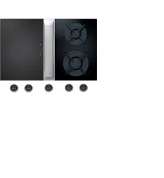
Supply voltage 220 – 240 V
Frequency 50/60 Hz
Maximum power consumption 550 W
Power supply cable length 2 m
Dimensions (width x depth x height) 468 x 540 x 199 mm
Weight (incl. accessories/packaging) 12.5 kg
Cooktop extractor power levels 1 – 9, P
duct connection BORA Ecotube
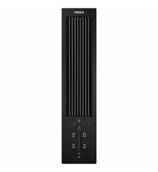
Product description
Intuitive control knob
Automatic cover ap
Premium design
Simple cleaning
Integrated grease drip pan
Genuine stainless steel grease lter
Modular system
Automatic extractor control
Maximum storage space
Integrated fan
Scope of delivery
Cooktop extractor system with integrated fan PKAS3
Control knob
stainless steel grease lter
Filter tray
Maintenance tray
cover ap
connection cable for the control knob
operating and installation instructions
height adjustment plate set
Mounting clamps
Power supply cable with type E + F plugs
Accessories
PKA1FF stainless steel grease lter
PKA1VK cover ap
PKA1FW lter tray
UNLI type I power supply cable (AUS)
UNLJ type J power supply cable (CH)
UNLG type G power supply cable (GB-IE)
UNLB type B power supply cable (PH)
UNLH type H power supply cable (IL)
product- and planning instructions
Suitable for use as a recirculation or exhaust system
Compatible with all BORA Professional 3.0 cooktops and BORA Universal fan
modules
Use of an additional fan module is possible for very long or complex exhaust
air channels
The worktop height can be adjusted as necessary
Worktop depth: ≥ 700 mm
Installation type: ush or surface-mounted
The drawers and/or shelves in the oor unit must be removable for
maintenance and cleaning purposes
The BORA Ecotube duct system is optimally tailored to the BORA cooktop
extractors and guarantees 100% functionality and optimum performance
The Professional cooktop extractor system can be combined with all BORA
sockets
Duct connection on the back of the appliance
PKAS3
BORA Pro cooktop extractor system with integrated fan
BORA Vertriebs GmbH & Co KG · Innstraße 1 · A-6342 Niederndorf · T +43 (0) 53 73 6 22 50 - 0 · [email protected] · www.bora.com
The device must not be installed above cooling devices, dishwashers,
stoves, ovens, washing machines or dryers.
●
53
BORA PROFESSIONAL 3.0
246
341
62
14,5
7
25
73
37
44
21
491
509
15,5
24,5
240
370
133,5 255,5
540
R3
BORA VENTILATION HANDBOOK
Technical data
Supply voltage 220 – 240 V
Frequency 50 / 60 Hz
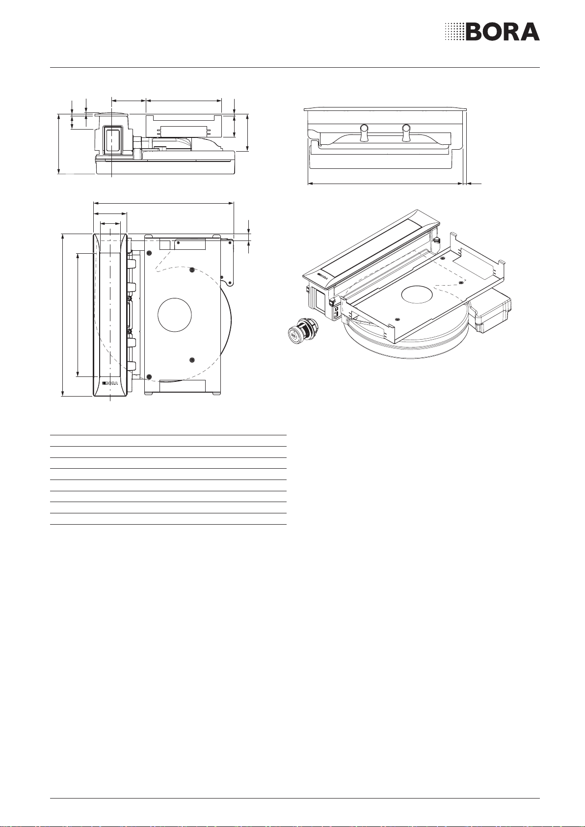
Maximum power consumption 5.0 kW
Maximum power rating 20 W
Minimum fuse protection 1 x 0.5 A
Power supply cable length 1,5 m
Dimensions (width x depth x height) 370 x 540 x 73 mm
Weight (incl. accessories/packaging) 11.5 kg
Surface material SCHOTT CERAN
®
Cooktop power levels 1 – 9, P
Size of front cooking zone Ø 240 mm
Size of rear cooking zone Ø 200 mm
Front cooking zone output (power burner) 850 – 3000 W
Rear cooking zone output (normal burner) 700 – 2000 W
Size of front pan support 270 x 270 x 25 / 50 mm
Size of rear pan support 235 x 235 x 25 / 50 mm
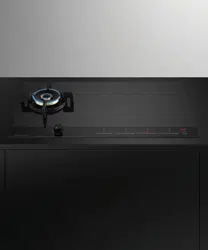
Product description
Intuitive control knob
Variable heat retention function
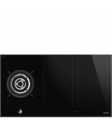
Sunken gas burners
Automatic reignition
Dishwasher-safe pan supports
Childproong feature
automatic heat up function
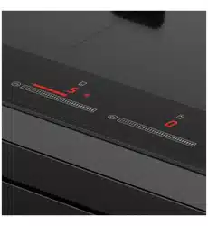
precise electronic control
residual heat display
Demo mode
Scope of delivery
Gas cooktop PKG3
2 x control knobs
2 x connection cables for the control knobs
2 x cast iron pan supports
Gas nozzle set G20/20 mbar natural gas
Connection cable to the extractor
operating and installation instructions
height adjustment plate set
mounting straps
Adapter cylindrical-conical
Seal
Accessories
BORA gas nozzle set natural gas G20/10 mbar PKGDS2010
BORA gas nozzle set natural gas G20/13 mbar PKGDS2013
BORA gas nozzle set natural gas G20/20 mbar PKGDS2020
BORA gas nozzle set natural gas G25/20 mbar PKGDS2520
BORA gas nozzle set natural gas G20/25 mbar PKGDS2025
BORA gas nozzle set natural gas G25/25 mbar PKGDS2525
BORA gas nozzle set liquid gas G30/G31 28-30/37 mbar PKGDS3028
BORA gas nozzle set liquid gas G30/G31 50 mbar PKGDS3050
BORA Pro gas nozzle set liquid gas G31/G30 mbar PKGDS3130
BORA Pro gas nozzle set liquid gas G31/50 mbar PKGDS3150
BORA burner set PKGBS
BORA pan support small PKGTK
BORA pan support large PKGTG
Product- and planning instructions
The gas connection tube must be provided at the installation site (thread
diameter 1/2“ cylindrical)
Ensure sucient air supply below the gas cooktop. Either over the front of
the body (opening cross-section > 50 cm²) or over the plinth area (opening
cross-section > 150 cm²)
Provide a return ow aperture (opening cross-section > 1000 cm² per air
cleaning unit) for recirculation in the plinth area
Please note the local regulations and connection requirements applicable to
gas cooktops
Please note the special installation and workmanship guidelines for the gas
cooktop (see the operating and installation instructions)
When operating a gas cooktop with a cooktop extractor, the gas ame can
be affected (depending on the height of the power level on the cooktop
extractor)
The performance characteristics of the gas cooktop (e.g. heating times,
eciency, etc.) are affected by the cooktop extractor. The cooktop extractor
also affects the heat input and distribution
If the gas cooktop is used in a model with two cooktop extractors, it is to be
installed at the side
Rotation by 180° possible during installation
PKG3
BORA Pro gas cooktop
BORA Vertriebs GmbH & Co KG · Innstraße 1 · A-6342 Niederndorf · T +43 (0) 53 73 6 22 50 - 0 · [email protected] · www.bora.com
The device must not be installed above cooling devices, dishwashers,
stoves, ovens, washing machines or dryers.
●
21
PROFESSIONAL
≥700
≥815
120
≥1400
≥700
≥199
≥900
≥810
≥870
≥900
≥700
≥900
≥900
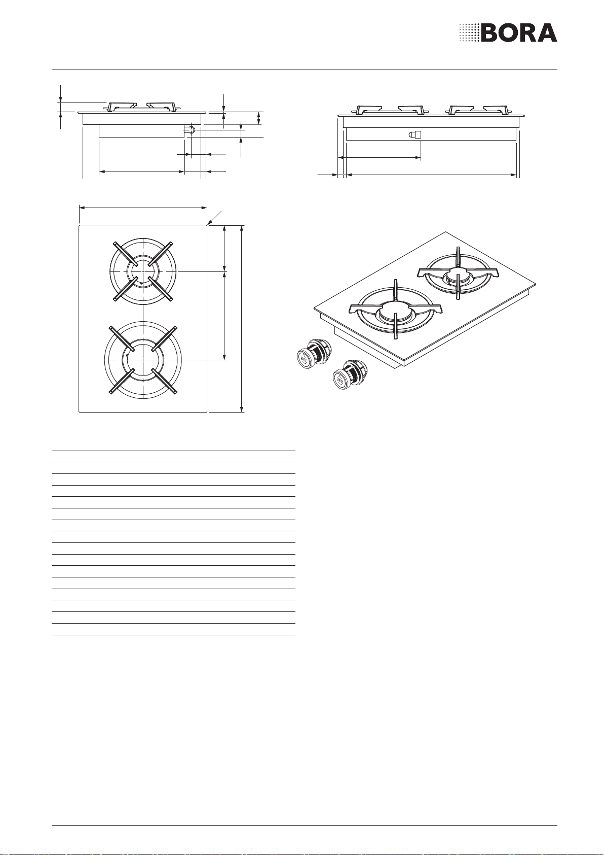
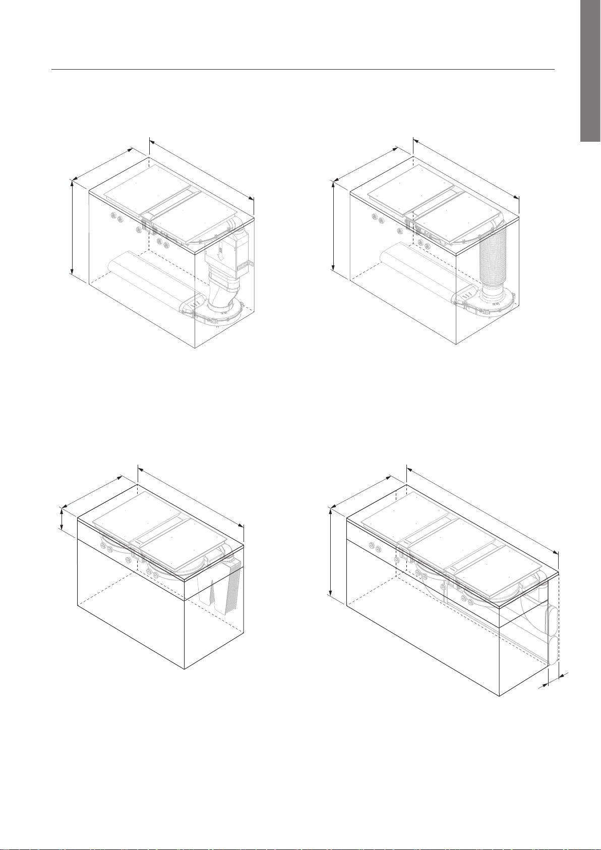
Minimum dimensions for installation
BORA Professional 3.0
Minimum dimensions for installation
PKA3 + UESDFSL:
Minimum dimensions for installation
PKAS3 + EFBV90 + ULBF:
Minimum dimensions for installation
PKA3 + UESDRSL:
Minimum dimensions for installation
2 PKAS3 (exhaust system):
(The bottom drawer must be shortened,
ULS plinth fan with air release to the left)
(ULS plinth fan with air release to the left)
19
PROFESSIONAL
x
A ±2
B ±2
544 ±2
≤ R5
≤ R5
≥ 74
(≥ 70)
516 ±2
≥ 700
7 +0,5
14
10 - 40
≥60
(
≥74
)
14x
x
B ±2
≤ R5
≥ 74
(≥ 70)
516 ±2
≥ 700
≥62
(
≥74
)
12x
12
10 - 40
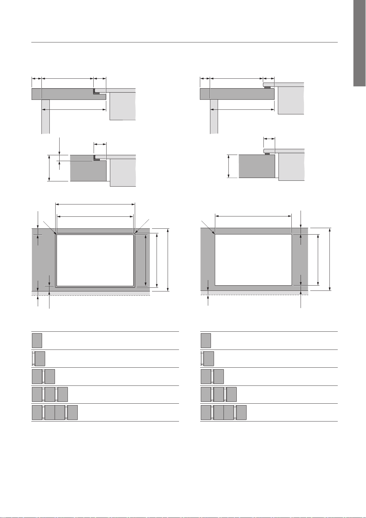
Cut-out dimensions
BORA Professional 3.0
Flush installation Surface mounting
Cooktops/cooktop extractor A in mm B in mm
1/0 374 346
1/1 485 457
2/1 856 828
3/2 1338 1310
4/2 1709 1681
Cooktops/cooktop extractor B in mm
1/0 346
1/1 457
2/1 828
3/2 1310
4/2 1681
Important planning instructions:
All dimensions from the front edge of the front cover.
Cut-out dimensions tolerance +/- 2 mm.
Clearance of 1 mm should be planned between the built-in appliances.
Clearance of 2 mm should be planned around the built-in appliances.
Please note the worktop manufacturer’s instructions with regard to the suitability of the worktop. Worktop cut-outs must be moisture-sealed using suitable
means or, where necessary, tted with a thermal insulator (e.g. in the case of Corian or HiMacs worktops).
18
PROFESSIONAL
Ø49
Ø58
Ø76
90
22 10-40 18
≥40≥70
Ø50 ±0,5
110
≥40≥70
Ø50 ±0,5
370
80-140
≥40≥70
90
Ø50 ±0,5
90 196 196
370 370
110
1 1
≥70 ≥40
90 196 196 90 196 196 90
370 370
370
110
1 1 1 1
110
Ø50 ±0,5
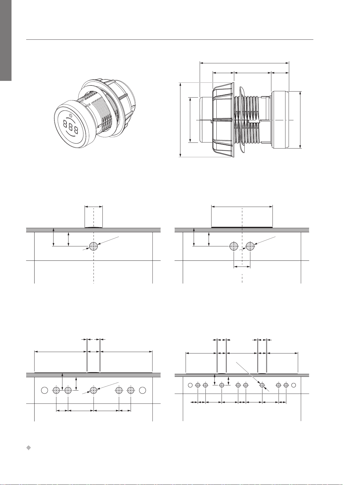
Control knob
BORA Pro control knob
Bore hole for the control knob on the
Professional cooktop extractor:
Bore holes for the control knobs on the
Professional cooktops:
Appliance and installation dimensions
Bore holes
Bore hole examples
Bore holes for installing 2 cooktops,
1 cooktop extractor
Bore holes for installing 3 cooktops,
2 cooktop extractors
≥40≥70
90 90 90
Ø50 ±0,5
90 196 196
370 370
110
1 1
3
1 2
4 3 65
= Control knob bore holes
≥40≥70
90 90 90
Ø50 ±0,5
90 196 196
370 370
110
1 1
3
1 2
4 3 65
25
PROFESSIONAL
1
1
1
1
1
2
2
3
3
5
6
4
4
7
8
9
12 13
11
10
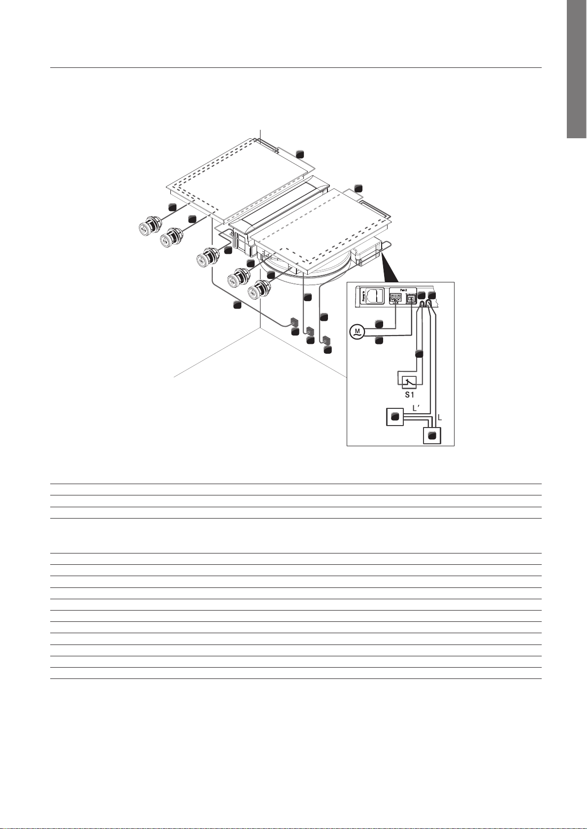
Connection diagram
BORA Professional 3.0
BORA Pro cooktop extractor system PKAS3
Position Description Note
1 Cable control knob – interface Length 1 m
2 Automatic extraction system cable Length 1 m
3 Cooktop power supply cable Length 1.5 m
4 Power supply per cooktop:
PKT3, PKC3, PKCB3, PKCH3
PKFI3, PKI3, PKIW3, PKG3
L1/L2/N/PE min. fuse protection 2 x 16 A
L/N/PE min. fuse protection 1 x 16 A
5 PKAS3/PKAS3AB power supply cable Length 2 m (country-specic)
6 PKAS3/PKAS3AB power supply
7 Fan 2 power supply cable
8 Fan 2 control line
9 Connection cable Home-In
10 Power supply for external device
11 External device e.g. electrically operated wall sleeve
12 Home-In connection 24V DC / 100 mA
13 Home-Out connection Maximum 250 VAC/ 30 VDC, 2.5A
M Fan 2
S1 External switch contact e.g. window contact switch for operating in exhaust mode with ues
The connection diagram shows the maximum connection options required and is for planning purposes only.
The connection itself must be carried out by a qualied specialist based on the operating instructions.