
SE_/ARS
CRnFrZMnN
MODEL NUMBER 917.259570 OWNER'SMANUAL
• Assembly
• Operation
• Customer Responsibilities
° Service and Adjustments
• Repair Parts
CAUT|ON: Read and follow all safety rules and instructions before operating this equipment,
FOR CONSUMER ASSISTANCE HOT UNE, CALL THIS TOLL FREE NUMBER: 1-800-659-5917
I
e
a
4
SAFETY RULES
Safe Operation Practices for Ride-On Mowers
IMPORTANTr THIS CUTTING MACHINE IS CAPABLE OF AMPUTATING HANDS AND FEET ANDTHROWtNG OBJECTS
FAILURE TO OBSERVE THE FOLLOWING SAFETY INSTRUCTIONS COULD RESULT IN SERIOUS INJURY OR DEATH
L
i
GENERAL OPERATION
Read. understand, and tottow atl Instructions tn the manual
end on the machine before starting
Only allow responsible adults, who are familiar with the
Instruction& to operale the machine,
Clear the area el objects such as rocks, toys, wire, eta,,
which could be picked up and thrown by the blade
Be sure the area ts clear of olher people before mowing Stop
machine ]f anyone enters lhe area
Never cam/passengers
Do not mow in reverse unless absolutely necessary Always
look down and behind before and while backing,
Be aware of Ihe mower discharge direction and do not point
It at anyone Do not operate the mower without either lhe
enlire grass catcher or the guard in place,
Slow down before turning
Never leave e running machine unattended. Always turn off
blades,set parklng 6rake_ stop engine, and remove keys
before dismounting,
Turn off blades when not mowing
Stop engine before removing grass calcher or unclogging
chute
Mow onty in daylight or good artificial ltghl
Do not operate Ihe machine while under the Intluenca of
alcohol or drugs
Watch lot tralfic when operating near or crossing roadways
Use extra care when loading sr unloading the machine into
a Irailer or truck,
IL SLOPE OPERATION
Slepes are a major factor related to loss-of-control and
tipover accidents, which can resuff in severe injury or
death. Allslopes require extra caution. If you cannot back
up the slope or if you feel uneasy on fl,do not mow iL
DO:
• Mow up and down slopes, not across
IIi. CHILDREN
Trag!e accidents can occur il Ihe operator is not aledto the
presence of children, Chftdren are often attracted to the
machine and the mowing acttvilyo Never assume that
children will remain where you rest saw them,
,, Keep chttdmnout ofthe mowing area and underthewalchfut
care of anolher responsible adult.
• Be alert and turn machine off ilchildren enter the area,
Before end when backing, took behind end down for small
children.
Never carry children They may fall oil and be seriously
injured or tntedere withsa[e machine operation
Never allow chiJdren to operate the machine
. Use extra care when approachingblind comers, shrubs.
tress,or other objects that may obscure vision,
IV_ SERVICE
• Use extracare tnhandllnggesotine andether luels They are
Ilammable andvapors are explosive
Use onty an approved container.
Never remove gas cap or add luel with the engine
running Allow engine to cool belore refueling Do not
smoke,
Never refuel the machine indoors
Never store the machine or Iuel container inside where
there Is an open flame, such as awater healer,
° Neverrun a maehtne Inside a closed area,
Keep nuts andbolts, especiallyblade attachment bolts, t_gh[
end keep equipment ingood condition
Never tamper with safety devices, Check their proper
operation regularly,
• Keep machine free elgrass, leaves, or otherdebds build.up,
Clean oil or luel spillage Allow machine to cool balers
storing
• Stop and Inspect Ihe equipment tf you slrike an object
Repair. tt necessary, balers restarting.
• Never make adjustments or repairs wilh Iheengine running
• Remove obstacles suchas rocks, tree limbs, etc.
•- --_._-,_.T-, ..................... _-, .................. ,- J--Grass ca char componen s ar&subiee, o.wear, damage, and
• Walctl tot r'0otes,ruts, or "bum s uneven terrain coots
....... P " . ..... delerisration, which could expose moving parts or al!ow
overturn file machine _=1stgratis can n/oe oos_aczes
obsets to be thrown, Frequentlycheck components and
• Uses!owspeed Chooseaiowgearsothalyouwiffnothave replacewIthmanufacturer'eresommendsdpads whennec-
to stop or ehft wh e on thesl0pe essary,
• Mower blades ai'esharp andcan cut Wrap theblade(s} or
wear gloves, and use extra cautionwhen servicing them
• Check brake operation hequentiy Adjust and service as
required,
i =
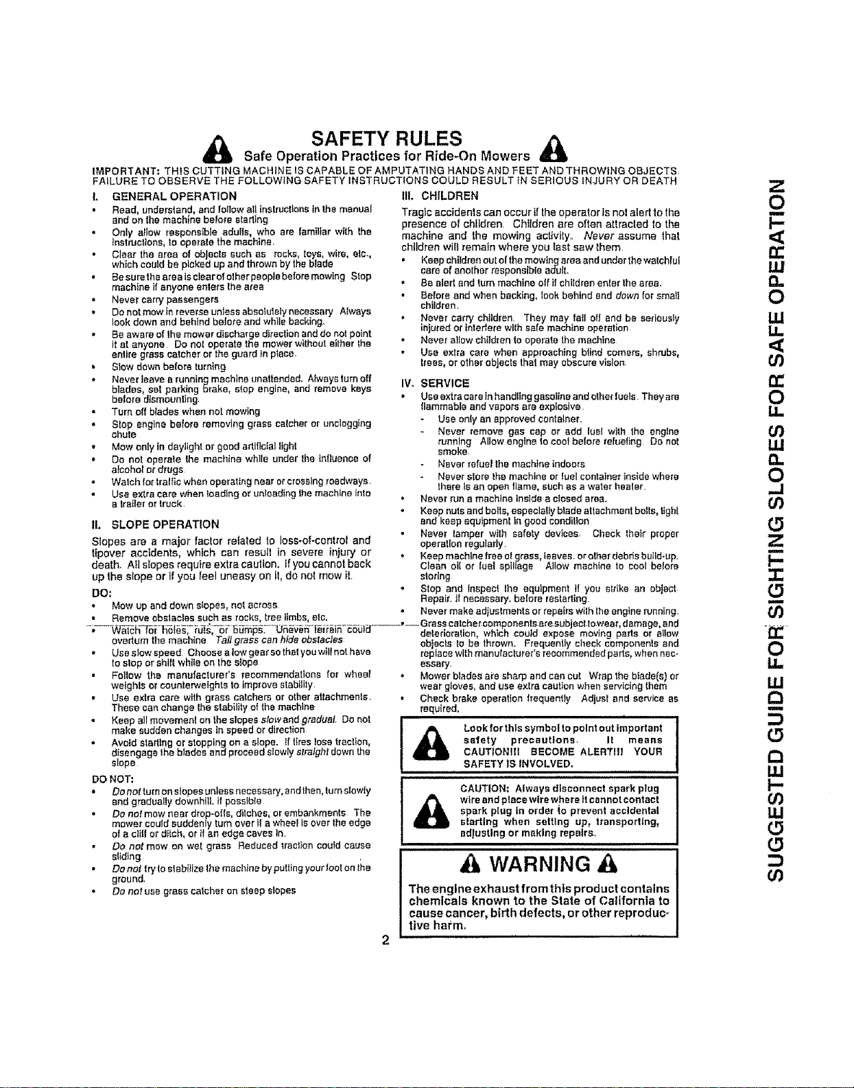
A Look forthls symbol to point out important
safety precautions- It means
CAUTIONIH BECOME ALERTll! YOUR
SAFETY IS INVOLVED.
• Fellow the manufacturer's resommendattons for wheal
weights or counter.,vstghteto improve atabilily
• Use extra care with grass catchers or ether attachments
Thesecan change {hestabilityofthemachlne
• Keep all movemenl on the slopes stow andgradual. Do not
make suddenchanges tn speed or direction
• Avoid stadtng or stopping on a slope. If tires lose tractisn,
disengage the blades end proceed slowly stralghl downthe
slope
DO NOT:
• Do not turnon slopes unless necessary, andthen, turnstowty
end graduallydownhill It possible
• Do not mow near drop-otis, ditches, or embankments The
mower could suddenly turn over t!a wheel isover the edge
of a clltl sr dltch, ortf an edge caves In
Do not mew on wet grass Reduced traction could cause
sliding
• Do not Iryto slabitlze themachine by putting yourtest on the
ground,
• Do nor use grass catcher on sleep slopes
CAUTION; Always dfsconnent spark plug
A wire and plecewlrswhsralt cannot contact
spark plug in order to prevent accidental
starting when setting up, transporting,
adlustlng or making repairs°
WARNING
The engine exhaust from this product contains
chemicals known to the State of California to
cause cancer, birth defects, or other reproduc-
tive harm,
n
l--
n-
UJ
U.I
14.
(1
cO
n-
O
u.
Or)
UJ
a.
0
.J
0
Z
F-
-i-
O0
0
U_
m
W
oO
0
O3

CONGRATULATIONS on your purchase of a Sears
Tractor ff has been designed, engineered and manufac-
tured to give you the best possible dependability and
pedormance
Shouid you experience any problem you cannol easiiy
remedy, please contact your nearest Sears Authorized
Service Center/Department Department, We have com-
petent, welt-tralnedtechniciansand the proper toolsto
service or repair this tractor..
Please read and retain this manual. The Instructions will
enabte you toassemble and mainlaln your tractor properly.
AIways observe the "SAFETY RULES".
MODEL
NUMBER 917 259570
SERIAL
NUMBER
DATE OF PURCHASE
TH E MODEL AND SERIAL NUMBERS WILLBE FOUND
ON A PLATE UNDER THE SEAT.
YOU SHOULD RECORD BOTH SERIAL NUMBER AND
DATE OF PURCHASE AND KEEP IN A SAFE PLACE
•"OR FUTURE REFERENCE.
MAINTENANCE AGREEMENT
A Sears Maintenance Agreement Is available on this prod-
uct. Contact you_ nearest Sears store tar details
PRODUCT SPECIFICATIONS
HORSEPOWER; 19.5 /
GASOLINE DAPACITY 3 5 GALLONS "_'
AND TYPE: UNLEADED REGULAR
OILTYPE (API-SFtSG): SAE 30 (above 32DF)
SHSAE 5W-30 {below 32_'F)
[OIL CAPACITY; 3,0 PINTS
SPARK PLUG: CHAMPION RJ19LM
(GAP: 030"}
VALVE CLEARANCE: INTAKE! 004"- 006"
EXHAUST: 007"-,009"
GROUND SPEED (MPH): FORWARD: 0- 5 5
REVERSE: 0-2.4
TIRE PRESSURE: FRONT: 14 PSI
REAR; t0 PSI
CHARGING SYSTEM: 3 AMPS SATTERY
5 AMP8 HEADLIGHTS
BATTERY: AMPiHR: 30
MtN CDA: 240
CASE SIZE: U1R
BLADE BOLT TORQUE: 80--,35FT..LBS
CUSTOMER RESPONSIBILITIES
,, Read and ebsewe the salety rdfes
• Follow aregular schedule in maintaining, cadng for and
using your tractor.
• FoIlow the Instructions under"Customer ResponsibilF
ties" and "Storage" sections of this owner's manuaf
WARNING: This tractor is equipped wilh an internal
combu_ion engine and should not be used on or near any
unimproved foresFcovered, brush._ 'vered or grass-coy..
eredland unless the engine's exhaust syslem Is equipped
with aspark arrestor meeting appl{cable'tocal or slate laws
(tf any). If a spark attester is used, it should be maintained
tn eflect_ve working order by the operator
In fhe state of California the above is required by law
(Section 4442 of the California Public Resources Coda).
Other states may haye similar laws Federal laws apply on
federal lands. A spark arrester for the muffler ts available
through your nearest Sears Authorized Service Center/
Department (See REPAIR PARTS seclion of this manual).
...............L|MITED-T-WO-YE-Ai:I-WAi-3RAN_ON CRAFTSMAN RIDING EQUIPMENT ...............
For two (2) years from the date of purchase, it this Crafisman Riding Equlpmenl ts maintained, lubdcafed and tuned up according
to the Instructions Inthe owners manual, SearS will repair or replace, free ef charge, any partsround to be defeclive in material or
workmanship.
This Warranty does net cover:
Expendable ilemewhich become worn dudng normal use, such as blades, spark plugs, aircleaners, bells, etc.
• Tirerepfacement er repair caused by punclurssfrom eulside objects, such as nails, lhems, stumps, or glass.
• Repairsnecessary because of operator abuse, negligence,tmpreper storage or accident or _nefaliure to mainlatn the
equipment according!o Ihe Instructions conlatnsd In the ewneCsmanual. '
• Riding equipment used for commercial er renta! purposes.
LIMITED 90 DAY WARRANTY ON BATTERY
For ninety (gO) days from date of pumhase, if any battery included with this riding equipment proves defective in matertat er
wmkmanshipand ourtesting determines the batterywItl nol holda cha_'ge,Sears willreplace lhe batte_' at no charge
IN-HOME WARRANTY SERVICE ON YOUR CRAFTSMAN RIDING EQUIPMENT IS AVAILABLE AT NO*CHARGE FOR 30
DAYS PROM THE DATE OF PURCHASE. PLEASE CONTACT YOUR NEAREST SERVICE CENTER. AFTER 30 DAYS FROM
THE DATE OF PURCHASE, WARRANTY SERVICE IS AVAILABLE BY TAKING YOUR CRAFTSMAN RIDING EQUIPMENT TO
YOUR NF.AREST SEARS SERVICE CENTER, (1N-HOMEWARRANTY SERVICE WILL STILL BE AVAILABLE AFTER 30 DAYS
FROM THE DATE OF PURCHASE BUT A STANDARD TRIP CHARGE WILL APPLY} THIS WARRANTY APPUES ONLY
WHILE THIS PRODUCT iS IN THE UNITED STATES
This War_nty gives you speOIlelegat dghts, and you may alsohaveether flgh'_swhichmay vary fmrn state Io state
SEARS, ROEBUCK AND CO, D/817 WA, HOFFMAN ESTATES, IL 60179
3

TABLE OF CONTENTS
SAFETY RULES ............................................................ 2
PRODUCT SPECIFICATIONS ........................................ ',.3
CUSTOMER RESPONSIBILITIES .,°o._............... 3, 17'-20
WARRANTY ................................................................. 3
'TABLE OF CONTENTS ............................................... 4
INDEX ............................................................................ 4
TRACTOR ACCESSORIES ............................................ 5
ASSEMBLY .............................................................. 7-10
OPERATION ............................................................. 11-t6
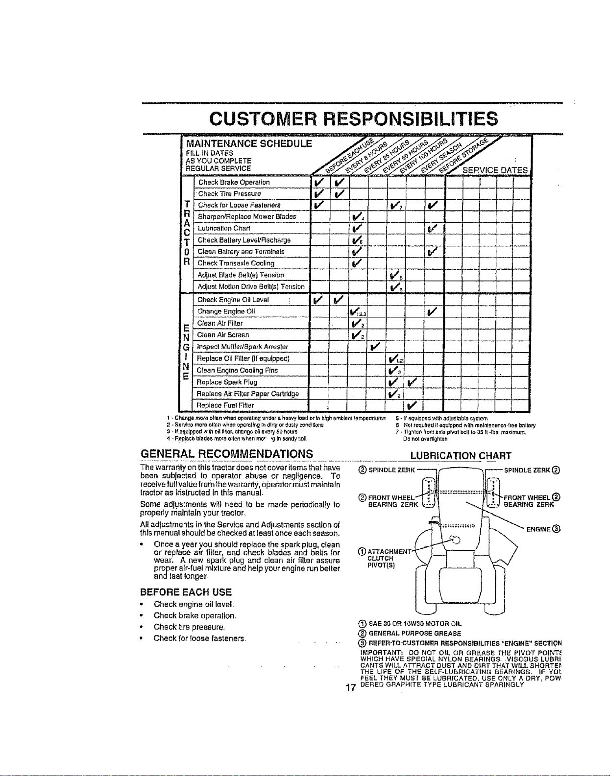
MAINTENANCE SCHEDULE ...................................... 17
SERVICE AND ADJUSTMENTS ............................ 2%27
STORAGE ...................................................................... 28
TROUBLESHOOTING ............................................ 29-30
REPAIR PARTS - TRACTOR ................................... 32-47
REPAIR PARTS - ENGINE ..................................... 48-53
PARTS ORDERINGJSERVICE ................... BACK PAGE
INDEX
A
Accessories ............................... 5
Adjuslmenls;
Brake ................................... 24
Carburetor ............................ 27
Mower:.
Front-To-Back.......... :.......... 22
Side-To-Side ..................;..... 22
Throttle Control Cable .......... 26-27
Air Filler, Engine,,_............................... lg
AirScreen, Engine ......................... lg
Assembly................................... 7-10
B
Battery:
Charging ...................................... 18
Cleaning ................................ 18
StadlngwithWeak Baltery ..........28
Storage ......................28
Ter_ntnels......................... 18
Belts:
Motion Drive
Removal/Replacement ......... 24
Mower Ddve
Removef/Reptacement ........... 23
Mower Blade Drive
Removal/Replacement .......... 23
Blade;
Sha_ening ................................. 18
E
Electrfcet:
Interlocks and Retays ............ 2B
SchemaIIc ................................ 31
Wiring Diagram ..............32
Engine:
AirFilter............................ 19
AirScreen ....................... 19
Coating Fins, Engine ................. 20
Oil Change .............. ,............... 19
OIl Level ........................ 14,19
Oil Type............................... 19
Preparelion ..................................14
Repair Parts ................... 48-53
Starting..................................... 14
Storage ................................. 28
F
Filters:
Air., ................................. t9
Fuel .... .............. ..... 20
Fuel:
Type ..............................................14
Storage ...................................... 2B
Fuse ........................................ 26
G
Gauge Wheel8 ............................... 9,14
H
Brake Adjustment ......................... 24
C
Carburetor Adiustment .................... 27
Controls, Tractor ............................... 13
Cuslomer RespensibI!Ittes..........3,17-20
Engtne:
Air Filter .............................. ig
Air Screen, Engine .................. 19
Battery .........................................18
CoolingFins, Engine..................19
Engine eli ..........................20
Fuel Filter ................................ 20
Bpa_'kPlugs ......................18
Trecton
Blades ............................. I 8
Lubrication Chart .. ............... 17
Maintenance Schedule . .. 17
Tire Care .......... .... B,18,25
Cutting Heighl, Mower ........................ 13
L
Leveling Mower Deck .......... 21-22
Lubdcatlon Chart ..................... 17
M
Maintenance Scheduta ..................... 17
Mowec
Adjustment, Front-to-Beck, • -.22
Adjustment, Side-to.Side .......... 22
Blade Sharpening ...................... 18
BIade Replacement .................. !8
Cutting Height ......................... 13
Installation .................................9,21
Opera!ion..................... 11..16
Removal ................... 21
Mowing Tips ................... :...... 16
Muffler .............. .......................... 20
Spark Arrestor ..................... 3,40
Muleher Plate ............................ 10
4
O
eli:
Cold Weather Conditions ...... t4, tg
Engine...................................... 19
Storage .................................. 28
Operalion ........................................11=!6
Operaling Mower ..................... 14
Options,"
Accessories.............................. 5
Spark Arrestor ..................... 3,40
P
Parking Brake .......................... 12-13
Parts Bag ............................. 6
Paris, ReplaeamenVRepa_r ....... 32-47
Product Specificatlons .............................3
R
Repair Parts ...................... 32-47
S
Solely Rules...................... .......... 2
Seat ............................................... B
Service and Adjustments .............. 21-27
Brake ............................................ 24
Carburetor ...................... 27
Fuse. ................................... 26
Hood Removal/Installation ........ 26
Motion Drive Belt
RemovallReplacement ........... 24
Removal/Replacement ......... 23
Mower Blade Drive Serf
Removal/Replacement........ 23
Mower Adjustment:
Front-to-Back ................... 22
Side-to*Side .............................22
Mower Installation ................... 21
Mower Remove{ ......................... 2!
TireCare ....................... B,18,25
Slope GuideSheet ............................. .55
SparkPlugs.................................... 20
Specifications ....................................... 3
Startingthe Engine ................ 14-15
Steedng Wheel .................... 7,25
StoppingtheTractor ...................... I3
Storage .................................... 28
T
Throttle Control CableAdjustmenl ..,.26
Tires.................................. 8,18,25
Trouble Shooting Chad ............. 29*30
Transax[e Repair Parts ......... 46-47
W
Wa_'ar_ty............................................... 3
Wiring Diagram ............................... 32
Wiring Schematic ....................... 31
ACCESSORIES AND ATTACHMENTS
These accessoriesend attachmentswereavailable through most Sears retatloutlets endservicecenters whenIhetractor waspurchased
Moat Sears stores can order these iiems for you when you provide the model number of your Iractor_
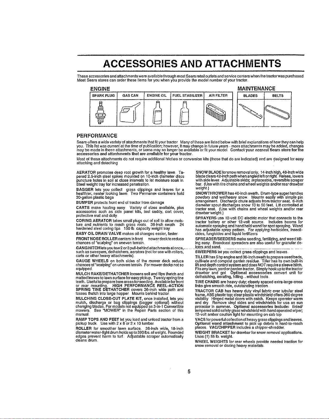
ENGINE
SPARKPLUG GASCAN ENGINEOIL
FUELSTABILIZER
AIRFILTER
%
MAINTENANCE
BLADES BELTS
PERFORMANCE
Searscriersawide vadetyof altachments Ihaffityour Iracior Many el theseare listed below withbr{el explanations el howthey canharp
you. This list was currant al the time of pub]]car!on; however, Itm_y change infuture years -,more attachments may be added, changes
may be made in these attachments, or some may no longer be available ortit your model Contact you_"ncarest Sears stnl'e lot the
accessories and attachments that are available for your trector_
Most el theseattachments de not require additional hits]lea orconversion kfls (Ihese thatdo are indicated) and ere designed for easy
attachingand detaching
AERATOR promotes deep root growlh for a healthy lawn Ta-
pered 2.5-inch sisal spikes mounted on to-inch diameter discs
puncture holes In soil at dose intervalsto let moisture soak in
Stee_weighttray lot Increased penetration
BAGGER lets you collect grass clippings and leaves {or a
healthier, nearer looking lawn Two Permanex containers hold
30-gallon plasttcbags
BUMPER protects frontend el tractorfromdamage
CARTS make hearing easy Vsdety ofsizes available, plus
accessories such as aide panei klls, tool caddy, cad cover,
protectivemat and deify
CORING AERATOR takessmatl plugs outof soil Ioa!iow mois-
ture and nutrientsto reach grass roots. 36-Inch swath 24
harder_edsteel coring tips 150 Ib capacityweight tray
EASY OIL DRAIN VALVE makes oil changes easier, faster
SNOW BLADEforsnow removafonly, f4_lnshhigh,48-1nobwide
blade clears42-inch pathwhenangled Ieftor dght. Raises,lowers
withsidelever. Ad ustable skids; replaceable,reversiblescraper
bar_(Use w Iht rechainsandwheel weighls andler rear drawbar
weight}
SNOWTHROWER has 40Jnch swath. Drum-typeauger handles
powderyand weliheavy snow Mounts easily wilh simple pin
arrangement. Discharge chute adjustsfromtractorseet. 6-Inch
dtameter spoutdischarges snow10 to 50 feet. Lift controlledat
tractor seat. (Use with chains and wheel weights and/or rear
drawbar weight.)
SPRAYERS use 12-volt DO etecidcmotor thatconnecls to the
tractor baltery or other 12-volt source, Includes booms for
automaticsprayingandhand held wandfor spotspray{rig. Wand
has adjustable spray paftem. For applying herbicides, insecli.,
oides, lung_ctdesand liquid terltllzers
FRONTNOSEROLLERsanterslnfrunt :nowerdecktoraduce SPREADER/SEEDERSmakeseedlng fertfttztng,and weed ktU-
chances of "scalping" on uneven terrain_ " ]rigeasy. Broadcast spreaders am atso useful for granular de÷
GANGHtTCH lets¥ou tow2or3pull-behind attachmentsatonce,-........ ]cefs.and_s_nd_...........................................................
such as sweepers, dethatchers, aerators (notforusewithrollers, SWEEPERS let you co{leergrass c_lpplngsand leaves.
cartsor other heavy attachments)
TILLER has 5hpengine and36-Inch swathtoprepareseed beds,
cultivate and compostgardeh residue.Tiller has itsownbunlJri
lilt anddepth controisystem anddoes NOTrequire esleevehilch.
Fitsany lawn,yardor garden tractor,S_mplyhook upto thetractor
drawbar and go] Optional accessories convert unit for
dathatching, aerallng,hilling ..without tools
GAUGE WHEELS on both sides of the mower deck reduce
chance_,of "sea{ping"on uneventerrain Formower decks notso
equipped
MULCH RAKFJDETHATCHER loosens soil and Itlpsthatch and
matted leaves tolawn audace foreasypickup, Twenty springline
teeth_Usefulto preparebare areas for seeding. Available for front
or rear mounllng. HIGH PERFORMANCE REEL-ACTION
SPRING TINE DETHATCHER covers 36-1richwide path and
tosses thatch Intolarge hopper Mounts behind tractor
MULCHING CLOSE,OUT PLATE KIT, once tnstafled,lets you
mulch, discharge or bag clippings (bagger optional) without
changingblades. For models not equippedas 3-1n-tConvertible
mowers See "MOWER" in the Repair Parts section of this
manual
RAMP TOPS AND FEET tel you load and untoadtractor trom a
pickuptruck Use with2 x 8 or 2 x 10]umber
ROLLER for smoother Eawnsudace_ 36Jnch wide, 18-Inch
diameter warer-tightdrum holdsupto3g0 tbs.el weight, Rounded
edges prevent harm to tuff Adjustable acrsper automalicelly
cleans drbm
TiRE CHAINS are heavy duty; olosetyspacedexits-large crosS
linksgivesmoothride, outstanding traction.
TRACTOR CAB has heavy duty vinylfabric over tubular steel
frame, ASS plastic top; clearplastic windshieldoffers 360 degree
visibility Hinged metal doors withcatch. Keeps operator warm
and dry Remove vinylsides and wlndshte]ds for use as sun
protectorin summer, Optional accessories Include: tinted/
tempered soJIdsafety glass windshieldwilhhand operated wiper,
'{2-volt ambercaution ttghl for mounting on cab top
VACS Iorpowedul coltecl_onel heavy grass clippingsandleaves.
Optional wand attachment to ptck up debris tn hard-to-reach
pisces VAC/CHIPPER includesa chtpper-shredder
WEIGHT BRACKET lot drawbar forsnowremovalepp_tcatEons,
Uses (I) 55 lb. weight.
WHEEL WEIGHTS for rear wheels provide needed Iractianfor
snow removalor dozing heavy materials.
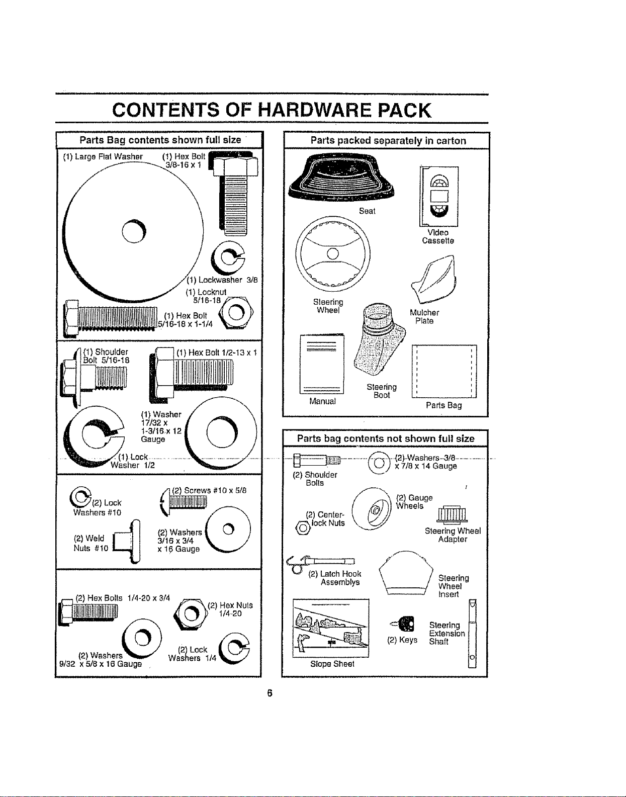
CONTENTS OF HARDWARE PACK
i i
Parts packed separately in carton
(1) Washer
17/32 x
1-3/16x 12
Gauge
Lock
1/2
(1) Shoulder
Bolt 5/16-18
(1) Hex Bolt 112-13 x 1
(_(2) Lock
Washers #10
(2) Weld _
Nuts #10
s #10 x 5/8
(2) Washers i'i/_(_ 'XI
3118×3f4 \ /
x 16 Gauge
(2) Hex Bolts 1/4-20 x 3/4
,,/r"_"k(2 ) Hex Nuts
(2)Lock
• (2) Washer Washers 1t4
9/32 x 5/8 x 16 Gauge
Seat
Video
Casselte
Steedng
Wheel
Pads Bag
..{2)-Washers=3!8 .............
(2) Shoulder x 7/8 x 14 Gauge
Bolts
/f_(2) Gauge
Wheels
(2) Center-
Qlock Nuts
Steertng Wheel
Adapter
k _"¢_7_ _ Steering
Assemblys Wheel'
Insert
Slope Sheet
ASSEMBLY
Your new tractor has been assembled at ihe factory with exception of these parts left unassembled for shtpping purposes,
To ensure safe and proper operation of your tractor afl parts and hardware you assemble must be tightened securely. Use
the correct tools as necessary to insure proper tightness
TOOLS REQUIRED FOR ASSEMBLY
A socket wrench set wtflmake assembly easier. Standard
wrench sizes are listed,
(1) 9/16" wrench (1) 3/'4" Socket w/drive rachel
(2) 7/16" wrenches Phillips Screwdriver
(2) t12" wrench Tire pressure gauge
(1) 3/4" wrench Utility knife
Pliers
When right or left hand is mentioned in this manual, it
means when you are in the operating position {sealed
behind the sleedng wheel)
i
TO REMOVE TRACTOR FROM CARTON
UNPACK CARTON
,, Remove al! accessible loose parts and parts cartons
from carton (See page 6),
• Cut, from top to bottom, along lines on all four corners
of carton, and lay paneIs fiat,
- Check for any additional loose parts or cartons and
remove
BEFORE ROLLING TRACTOR OFFSKID
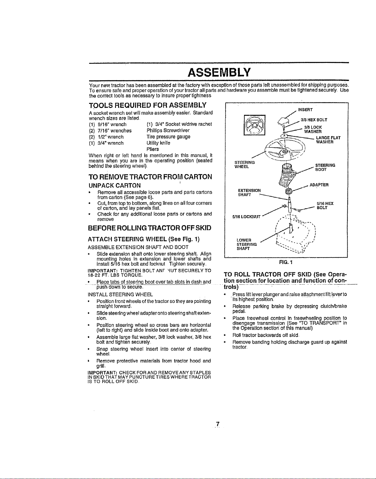
ATTACH STEERING WHEEL (See Fig. 1)
ASSEMBLE EXTENSION SHAFT AND BOOT
,, Slide extension shaft onto lower steedng shaft. Align
mounting holes tn extension and lower shafts and
install 5t16 hex bolt and rocknut Tighten securely,
IMPORTANT: TIGHTEN BOLT ANt _IUT SECURELY TO
t8-22 FT. LBS TORQUE.
5/16 HEX
BOLT
• Placetabsof steeringbootovertabslotsindashand
..........._iJ_-_0-s_u-r_,
TO ROLL TRACTOR OFF SKID (See Opera-
tion section for location and function of con=
_'trois) ................... _...............................................-----
iNSTALL STEERING WHEEL
• Position frontwheels of the tractor so they are pointing
straight forward,
• SHde steering wheei adapter onto steedng shaft exten-
sion,
• Pes_lion steering wheel so cross bars are horizontal
(left to right) ands]_de Inside boot and onto adapter,
• Assemble large flat washer, 3/8 lock washer, 3/8 hex
bolt and tighten securely
• Snap steering wheel insert into center of steering
wheel,
Remove protective materlals from tractor hood and
gdil,
IMPORTANT: CHECK FOR AND REMOVE ANY STAPLES
tN SKID THAT MAY PUNCTUR ETIRES WHERE TRACTOR
IS TO ROLL OFF SKiD
• Press l/It lever plunger and raise attachment lifttever to
tts highest position,, " .........
• Release parking brake by depressing clutch/brake
pedal.
• Place freewheel control In freewheeIfng position to
disengage transmission (See "TO TRANSPORT" in
the Operat{on secUoti of this manual)
• Roll tractor backwards off skid.
,, Remove banding holding discharge guard up against
tractor_
7
ASSEMBLY
i i ml ii ,inll,n,mnllllu i i t U
HOW TO SET UP YOUR TRACTOR
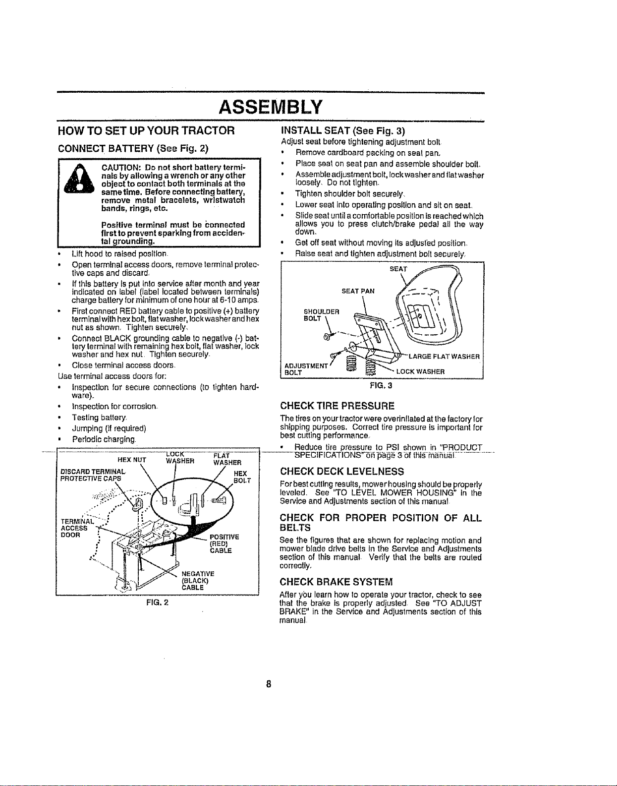
CONNECT BATTERY (See Fig. 2)
CAUTION: Do not short battery termi-
nals byallowing awrench orany other
object to contact both terminals at the
samettme. Before connecting battery,
remove metal bracelets, wristwatch
bands, rings, etc.
Positive terminal must be 5onnected
flrstto prevent sparking from acciden_
ta! grounding,
• Lilt hood to raised position.
• Open terminal access doors, remove termlnai protec-
tive caps and discard,
If this battery Is put into service after month and year
indicated on label (label located between terminals)
charge battery for minimum of one hour at 6-10 amps.
• First connect RED battery cable to positive (+) batlery
terminal with hex bolt, flat washer, lock washer and hex
nut as shown. Tighten securely_
, Connect BLACK grounding cable to negative (-) bat-
tary terminal with remaining hex bait, flat washer, lock
washer and hex nut. Tighten securety
• Close terminal access doors.
Use terminal access doors for:
, inspection for secure connections (to lighlan hard-
ware).
• Inspection for corrosion
• Testing battery,
• Jumping (if required)
• Periodic charging
"LOCK- FLAT
HE}( NUT WASHER
DISCARD TERMINAL, HEX
PROTECTIVE CAPS BOLT
.- -.r
TERMINAL "
ACCESS
DOOR
=-
%
POSITIVE
(BED)
CABLE
NEGATIVE
(SLACK}
CABLE
FIG. 2
illl Ill
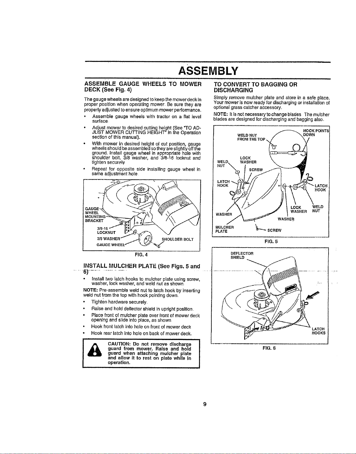
INSTALL SEAT (See Fig. 3)
Adjust seat before tightening adjustment bolt
* Remove cardboard packing on seat pan°
o Place seat on seat pan and assemble shoulder bolt.
, Assemble adjustment bolt, lockwasher and flat washer
loosely, Do not tlghlen_
- Tighten shoulder bolt securely.
• Lower seat inlo operating position and sit on seat,
• Slide seat until a comfortable position isreached which
a!lows you to press clutch/brake pedal aH the way
down,
• Get off seat without moving its adjusted position.
• Raise seat and tighten adjustment bolt securely,
SEAT
SEAT PAN
SHOULDER
BOLT
BOLT
FiG. 3
CHECK TIRE PRESSURE
The tires on your tractor were ovednflaled at the factory |or
sh{pptng purposes_ Correct tire pressure is important lor
best cutting performance,
• Reduce tire pressure |o PSI shown in "PRODUCT
SPECIFICA'T!ONS'55 =p_g_ 3 5f tht_,=m_bU_[;.....................
CHECK DECK LEVELNESS
Forbest cutttngresults, mowerhoustng shoutdbeproperly
leveled. See 'TO LEVEL MOWER HOUSING in lhe
Service and Adjustments section of thismanual
CHECK FOR PROPER POSITION OF ALL
BELTS
See the figures that are shown for replacing motion and
mower blade drive betts in the Service and Adjustments
section of this manual- Vedfy that the belts are routed
correctly,
CHECK BRAKE SYSTEM
After ybu learn how to operate your tractor, check to see
that the brake is properly adjusted, See "TO ADJUST
BRAKE" in the Serv{ce and Adjustmenfs section of this
manual
ASSEMBLY
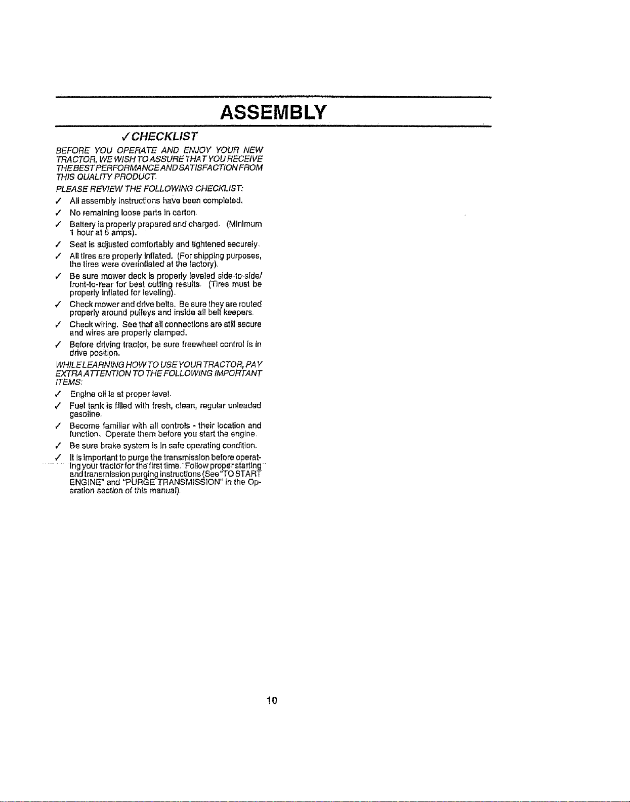
ASSEMBLE GAUGE WHEELS TO MOWER
DECK (See Fig. 4)
The gauge wheels are designed tokeep the mower deck In
proper position when operating mower Be sure they are
properly adjusted to ensure optimum mower performance,
,, Assemble gauge wheels with tractor on a flai level
surlace
• Adjust mower to desired cutting height (See "TO AD-
JUST MOWER CUTTING HEIGHT in the Operaiion
section of this manua0.
• With mower in desired height of cut position, gauge
wheels should be assembled so they are slightly off lhe
ground. Instaif gauge wheel in appropriate hole with
shoulder boil, 3/8 washer, and 318-16 Iocknut and
tighten securely
• Repeat for opposite side Installing gauge wheei in
same adjustment hole
GAUGE
WHEEL
TO CONVERT TO BAGGING OR
DISCHARGING
Simply remove mulcher plate and store in a safe place,
Your mower Is now ready for discharging or installalton of
optionaI grass catcher accessory.
NOTE; It is not necessary to change blades The mulcher
blades are designed for discharging and bagging also.
WELD NUT
FROM THE TOP
WASHER
MULCHER
PLATE
LOCK WELD
WASHER NUT
FIG, 5
FIG. 4
INSTALL MULCHER PLATE {See Figs. 5 and
.....6)..........................
• fnstatl two latch hooks to muicher plate using screw
washer, lock washer, and we d nut as shown
NOTE: Pra-assemble weld nut to latch hook by inserting
weld nut from the top with hook pointing down,
,' Tighten hardware securely.
', Raise end hold deflector shield In upright position,
', Place front el mulcher prate over front ef mower deck
opening and slide into piece, as shown
, Hook front latch into hale on front ef mower deck
• Hook rear latch tnto hole on back of mower deck.
i ii_ll CAUTION: Do not remove discharge i
guard from mower, Raise and hold !
guard when attaching mulcher plate I
and allow it to rest on plate while in !
operatlon. !
DEFLECTOR
SHIELD
FIG. 6
LATCH
HOOKS
i i
ASSEMBLY
,/CHECKLIST
BEFORE YOU OPERATE AND ENJOY YOUR NEW
TRA CTOR, WE WISH TO ASSURE THAT YOU RECEIVE
THEBES T PERFORMANCE AND SA TISFA CTION FROM
THIS QUALITY PRODUCT.
PLEASE REVIEW THE FOLLOWING CHECKLIST."
,." All assembly instructions have been completed,
/ No remaining loose paris in cation,
v" Batteryis properly prepared and charged_ (Minimum
1 hour at 6 amps).. '
,/" Beat is adjusted comfodably and tightened securely,
€" All tires are properly Inflated. (For shipping purposes,
the tires were ovennftated at the factory),
v" Be sure mower deck is properly leveled side-to-slde/
Iront-to-rear for best cutting results. (Tires must be
properly inflated for teveting)_
v" Check mower and drive belts. Be sure they are routed
properly around pulleys and inside el! bell keepers,
/ Check wiring. Bee that all connections are stiff secure
and wires are properly clamped.
.," Before driving tractor, be sure freewheel control is in
drive position.
WHILE LEARNING HOW TO USE YOUR TRACTOR, PAY
EXTRA ATTENTION TO THE FOLLOWING IMPORTANT
ITEMS:
,/ Engine oil is at proper level
7" Fuel tank is filled with fresh, clean, regular unleaded
gasoline,,
,/ Become familiar with afl controls - their location and
function, Operate them before you start the engine,
/ Be sure brake system is tn safe operating condition.
v" It is Important to purge the transmission before operat-
....... lngyourtractdrfortheflrsttim_:Fotlowproperstartlng
and transmission purging instruclions (See"TO START
ENGINE" and "PURGE TRANSMISSION" tn the Op-
eration section of thts manual),
10

u,u ,un u i uuuuulnllll i i
OPERATION
,ipllJ,umHn i i in i i i
These symbols may appear on your tractor or in (I1erature supplied with the product. Learn and understand their meaning,
4),
BATTERY CAUTION OR REVERSE FORWARD FAST SLOW
WARNING
ENGINE ON ENGINE OFF OIL PRESSURE CLUTCH LIGHTS ON LIGHTS OFF
FUEL CHOKE MOWER HEIGHT DIFFERENTIAL PARKING BRAKE UNLOCKED
LOCK LOCKED
MOWER LIFT
REVERSE NEUTRAL HIGH
ATTACHMENT
CLUTCH ENGAGED
ATTACHMENT
CLUTCH DISENGAGED
IGNITION
DANGER, KEEP HANDS AND FEET AWAY
HYDROSTAT)C FREE WHEEL
(Hydro Models only)
11
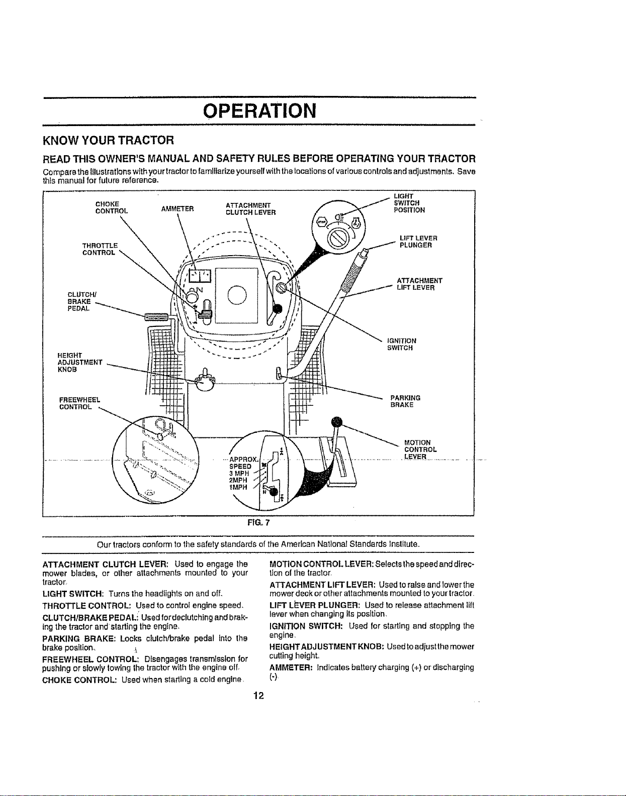
KNOW YOUR TRACTOR
READ THIS OWNER'S MANUAL AND SAFETY RULES BEFORE OPERATING YOUR TRACTOR
Compare the {tlustratlonswith your tractor to famlffarize yourself withthe locations of varlouscontrols and adjustments, Save
this manual for future reference.
LIGHT
CHOKE ATTACHMENT SWITCH
CONTROL AMMETER CLUTCH LEVER POSITION
THROTTLE
CONTROL _-_
CLUTCH/
PEDAL
©
ATTACHMENT
LtFT LEVER
HEIGHT
ADJUSTMENT
KNOB
FREEWHEEL
CONTROL
PARKING
BRAKE
-,APPRGX,
SPEED
3 MPH
2MPH
1MPH
MOTION
CONTROL
LEVER
FIG. 7
Our tractors conform to the safety standards of the American Nationa! Standards lnslltute.,
ATTACHMENT CLUTCH LEVER: Used to engage the
mower blades, or other attachments mounted to your
tractor,
LIGHT SWITCH: Turnsthe headlightsonand off.
THROTTLE CONTROL: Usedto controlenginespeed,
CLUTCH/BRAKE PEDALi'Usedfordeclutehing andbrak-
ingthe tractor andstarling the engine_
PARKING BRAKE: Locks ctulch/brake pedal into the
brake posittom
FREEWHEEL CONTROL: Disengages transmissionfor
pushing or siowly towing thetractorwith the engine otL
CHOKE CONTROL: Usedwhen starting acold engine,
MOTION CONTROL LEVER: Selects the speed and direc-
tton of the tractor,
ATTACHMENT LIFT LEVER: Used to relse and lower the
mower deck or other attachments mounted to your tractor,
LIFT Li=VER PLUNGER: Used to release attachment ftit
lever when changing its position,
IGNITION SWITCH: Used for starting and stopping the
engine,
HEIGHTADJUSTMENT KNOB: Usedto adjustthe mower
curling height,,
AMMETER: _ndicates battery charging (+) ordischarging
(-)
12
OPERATION
l _ The operation of any tractor can result in foreign objects thrown into the eyes, which can result
In severe eye damage. Always wear safety glasses or eye shlelds while operating your tractor
or performing any adjustments or repairs° We recommend a wide vision safety mask over the
,
spectacles or Standard safety glasses.
11 .........
HOW TO USE YOUR TRACTOR
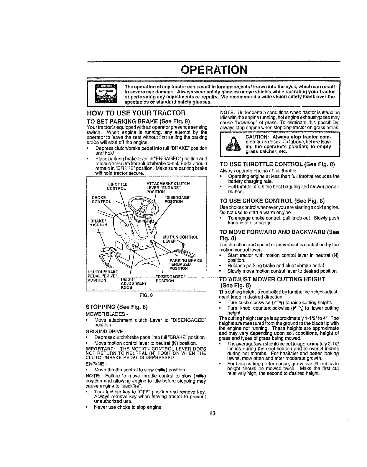
TO SET PARKING BRAKE (See Fig. 8)
Yourtractor is equipped with an operator prssenc esensing
switch, When engine ts running, any altempt by the
operator to leave the seat without first seI{ing the parking
brake wilt shut off the engine
• Depress ctulchibmke pedal intofutt "BRAKE" position
and hold
• Piece parking brake fever in"ENGAGED" position and
release pressure from clutch/brake pedal. Pedal should
remain In "BR,_KE" position. Make sure paddng brake
wiIl ho{d tractor secure.
THROTTLE ATTACHMENTCLUTCH
CONTROL LEVER _'ENGAGE"
POSmON
CHOKE "'DISENGAGE"
CONTROL mON
MOTFON CONTROL
PARK|NGBRAKE
"ENGAGED"
POSmON
CLUTCH_RAKE
REOAL_DRWE3-......................... _DISENGAGED!_............
POSITION HEIGHT POSITION
ADJUSTMENT
..... _NOe ............
FIG_ 8
STOPPING (See Fig° 8)
MOWER BLADES -
* Move attachment clutch Lever to "DISENGAGED"
position.
GROUND DRIVE -
• Depress clutch/brake pedal into full "BRAKE" position.,
. Move motion control fever to neutral (N) position.
IMPORTANT: THE MOTION CONTROL LEVER DOES
NOT RETURN TO NEUTRAL IN) POSITION WHEN THE
CLUTCH/BRAKE PEDAL IS DEPRESSED
ENGINE -
• Move throttle control to stow (,,Ill) posffion.
NOTE: Failure to move throttle control to slow (._I)
pos{tton and allowing engine to _dfe before stopping may
cause engine to "backfke",
• Turn Ignition key to "OFF" position end remove key.
Atways remove key when leaving tractor to prevent
unauthorized use
• Never use choke to stop engine.
NOTE: Under certain conditions when tractsr ts standing
Id}ewith the engine running, hot engine exhaust gases may
cause "browning" of grass,, To ei{minate Ibis possfbt{ity,
always stop engine when stopping tractor on grass areas,
pletely, as descrtb_.d abo_a, before leav-
Ing the operator's position; to empty
grass catcher, etc.
TO USE THROTTLE CONTROL (See Fig. 8)
A{ways operate engine at fu{I throttle.
- Operating origins at tess than fufl throttle reduces the
battery charging rate
• Full throttle offers the best baggtng and mower perfeF
mance.
TO USE CHOKE CONTROL (See Fig, 8)
Use choke contro{whenever you are stading acoid engine.
Do not use to start a warm engine,
• To engage choke control, pull knob out. SIowly push
knob in to disengage.
TO MOVE FORWARD AND BACKWARD (See
Fig. 8)
The direction and speed of movement ts conlrolled by the
motion control lever.
• Start tractor with motion control lever in neutral (N)
position,
. Release parking brake and clutch/brake pedal r
• Slowly move motion control fever lo desired position
......TOADJUSTMOWER CUTTING HEIGHT -
(See Fig, 8)
The cuiting heigh| iS-c0ntrotledby turning the height adjust-
ment knob in desired direction,
• Turn knob clockwise (_) to raise cutting height.
• Turn knob counterc{ockwise (P"_)to lower cutting
height.
The cutting height range tsapproximately 1.1/2" to 4" The
heights ere measured from the ground to the blade tip with
the engine not running These heights are approximate
and may vary depending upon soil conditions, height of
grass and types of grass being mowed.
• The average {awnshouid be cut to approximately 2-1/2
inches during the cool season and to over 3 inches
dudng hot months. For health{or and better looking
lawns, mow often and after moderale growth
• For best cuttingpedermance, grass over 6 inches In
height should be mowed twice. Make the first cut
relatively high; the second to desired height.
13
OPERATION
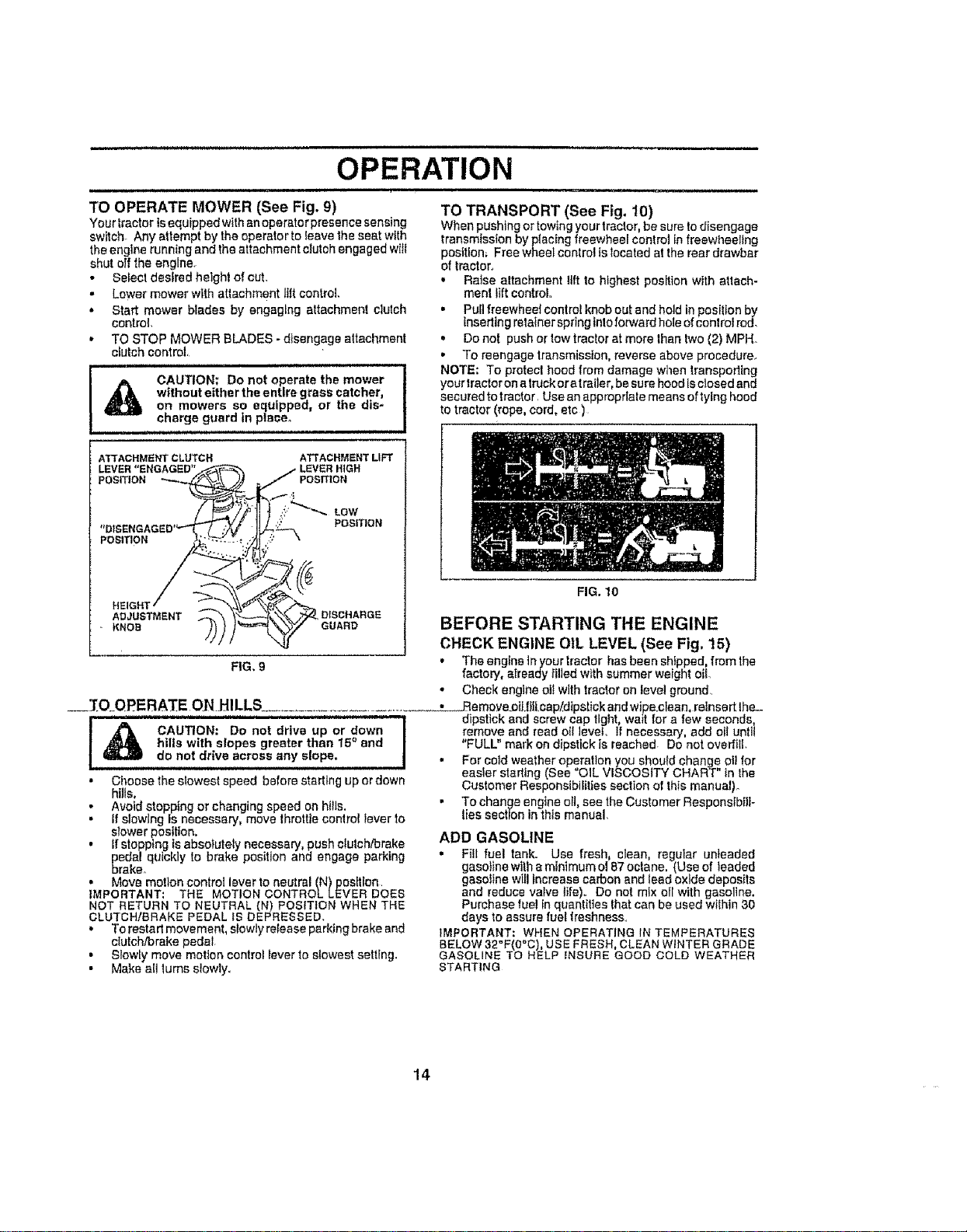
TO OPERATE MOWER (See Fig. 9)
Your tractor isequipped with an operatorpresence sensing
switch Any attempt by the operator to leave the seat with
the engine running and the attachment clutch engaged witI
shut off the englne_
• Select desired height of cut.
- Lower mower with atlachment lilt control
• Start mower blades by engaging attachment clutch
control.
,* TO STOP MOWER BLADES - disengage attachment
clutch control.
CAUTION; Do not operate the mower
without either the entire grass catcher,
on mowers so equipped, or the dis-
charge guard in plaoe_
ATTACHMENTCLUTCH ATTACHMENTLIFT
LEVER"ENGAGED"
POSITION POSITION
;'_'_'_- LOW
POSITION
POSITION . ;"_k
ADJUSTMENT DISCHARGE
KNOe GUARD
FIG. 9
TO TRANSPORT (See Fig, 10)
When pushing or towing your tractor, be sure to disengage
transmission by p(acIng freewheel control tn freewheeling
position_ Free wheel control is located at the rear drawbar
of tractor_
,, Raise altachmant lift to highest position with attach-
ment lift control
• Pull freewheel control knob out and hold in position by
Inserting retainer spring into forward hole of conlrol rod.
,, Do not push or low tractor at more than two (2) MPH_
• To reengage transmission, reverse above procedure_
NOTE: To protect hood from damage when transpodtng
yourtractor on a truck oratrailer, be sure hood Isclosed and
secured to tractor Use an approprlale means of tying hood
to tractor (rope, cord, etc )
FIG. 10
BEFORE STARTING THE ENGINE
CHECK ENGINE OIL LEVEL (See Fig. 15)
• Theenginetnyourlractor has been shippsd, fremthe
factory, already filled with summer weight oil
• Check engtne otl with tractor on level ground
___fO.OPERATE ONHILLS_. ....................... ___L_Remave.oII.liit.cap!d_pstick and wipe clean, relnsert lhe_
dipstick and screw cap tight, wmt for a few seconds,
! _ CAUTION: Do not drlve up or down I
._ hills with s!opes greater than 15° and
d O no! dr!re across any slope. • For cold weather operation you should change oil for
easier stadtng (See "OIL VISCOSITY CHART" in Ihe
" Choose the slowest speed before starting up or down
hills,
• Avoid stopping or changing speed on hills.
• If slowing is necessary, move throttle conlrot iever to
slower position.
• if stopptng is absolutely necessary, push e!ulchibrake
pedal quickly to brake position and engage parking
brake°
• Move motlon control lever to neutral (N)posttlon
IMPORTANT: THE MOTION CONTROL LEVER DOES
NOT RETURN TO NEUTRAL (N) POSITION WHEN THE
CLUTCH/BRAKE PEDAL IS DEPRESSED,
• To restart movement, slowly release parking brake and
dutch/brake pedal
• Slowly move motion control lever to slowest setting.
• Make all lums slowly.
remove and read oil level, If necessa0f, add oil until
"FULL" mark on dipstick is reached Do not overfliL
Customer Responsibilities section el this manual).
• To change engine ell, see the Customer Responsibili-
ties section in this manual.
ADD GASOLINE
• Fill fuel tank. Use fresh, clean, regular unleaded
gasoline wiih a minimum of 87 octane, (Use of teaded
gasoline will _ncreasa carbon and lead oxide deposits
and reduce valve life). Do not mix ell with gasoline.
Purchase fuel tn quantities that can be used wilhin 30
days to assure fuel freshness
IMPORTANT: WHEN OPERATING IN TEMPERATURES
BELOW 32"F(0"C), USE FRESH, CLEAN WINTER GRADE
GASOLINE TO HELP iNSURE GOOD COLD WEATHER
STARTING
14
WARNtNO:Expe,enoeindtcaie ihata co ol'b e'nd
fuels (called gasohot or using ethanol or methane 0 can
attract moisture which leads to separation and formation of
acids during storage Acidic gas can damage the fuel
system of an engine while in storage To avoid engine
probfems, the fuel system shouM be emptied before stor-
age of 30 days or longer. Drain the gas tank, start the
engine and let it run until the fuel lines and carburetor are
empty, Use fresh fue_next season See Storage Instruc-
tions for additional information. Never use engine or
carburetor cleaner products tn the fuel tank or permanent
damage may occur
i& CAUTION: Fill to bottom of gas tank "]
fgter necko Do notoverfiiL WIpe offany I
spilled oil or fuel= Do not etore_ spill or
use g.as,o!ine near an open tlome=:_.==j
TO START ENG!NE (See Fig. 8)
When starting the engine for the first time ,or if the engine
has run out el fuel, it will take extra cranking time to move
fuel from the tank to the engine,
" Be sure freewheel control is In the transmission on-,
gaged position.
• Sit on seal in operating position, depress clutch/brake
pedal and set parking brake,
• Place motion control lever in neutral (N) position
• Move attachment clutch to "DISENGAGED" position,
• Move throttle conlrot to fast (,,_) position
• Putl choke control out for a cord engine start altempt,
For a warm engine start attempt the choke co ntrol may
not be needed.
Note: Before starting, read the worm and cold startlng
procedures below
, Insedkeylntot_ntttonandturnkeyclockwlseto"START"
position and re ease key as see, as engine starts Do "
not run starter continuously for ors than fifteen sec-
ends per minute. If the engine does not start after
..... eeveraFatfempts; push=choke=controt inTwatt a few '
minutes and try again,. If engine st{Udoes not start, pul! •
the chg,ke cqr=trolout and relry.
WARM WEATHER STARTING (50" F and above)
• When engine starts, slowly push choke control in until
the engine begins to run smoothly. If the engine starts
to run'roughly, pull the choke control cut slightly for a
few seconds and then continue to push Ihe control in
slowly
• The attachments and ground drive can new be used, If
the engine does not accept the toad restart the engine "
and allow Itto warm up for one minute using the choke
as described above
COLD WEATHER STARTING (50 ° F and below)
• When engine starts, s}owly push choke control in until
the engine begins to run smoothly, Continue to push
the choke control in small steps allowing the engine to •
accept small changes in speed and toad unli! the
choke control is fully in, If the engine slarts to run
roughly, pull the choke control out slightly for a few
seconds and then continue to push the control In
slowly This may require an engine warm_up period
from several seconds 1oseveral minutes, depending
on the temperature° .
HYDROSTATIC TRANSMISSION WARM UP
• Before driving the unit in cold weather Ihe transmis-
sion should be warmed up as follows:
OPERATION
..i .H.,I H.. n I I I I .
• Be sure the tractor ts on level ground_
,, Place the motion control lever in neutral.
Release the parking brake and Ietthe clutch?arake
slowly return to operallng position,
• Allow one minute for transmtsslon to warm up.
This can be done during the engine warm up
period,
,' The attachments can be used dudng the engfne wan'n-
up period after the transmission has been warmed up
and may require Ihe choke control be pulled out slightly
NOTE: If at a Ngh aJlitude (above 3000 feet) or in cold
temperatures (below 32 F) the carburetor fuel mixture may
need to be adjusted |or best engine performance. See "TO
ADJUST CARBURETOR" tnthe Ser,,lce and Adjustments
section of this manual
PURGE TRANSMISSION
_ CAUTION; Neverengageordisengage I
freewheel leverwhfte the engine is run-
ning, ' "
To ensure proper operation and performance, it is recom_
mended that the transmission be purged before operating
tractor for the first time This procedure will remove any
trapped air inside the transmission which may have devel-
oped during shtpptng of your tractor,
IMPOR3-ANT: SHOULD YOU RTRANSMISSION REQUIRE
REMOVAL FOR SERVICE OR REPLACEMENT, IT
SHOULD BE PURGED AFTER REINSTALLATION
BEFORE OPERATING THE TRACTOR
" Place tractor safetyon level surface with engine off and
parking brake set.
• Disengage transmission by placing freewheel control
in freewheeling position (See 'TO TRANSPORT" In
this section of manual). '
Sitting tn the traclor seal, start engine After the engine
_vs running, move lhrotl{e controlte slew (.4R,) position.
ilh molten control lever in neutral (N) position, slowly
disengage clulch/brake pedal
Move motion control lever to fulI forwarcf p0sttton and
hold lot five (5) seconds, Move lever to lull reverse
position and hold for five (5) seconds, Repeat this
procedure three (3) times.
NOTE.' During this procedure there will be no movement of
drive wheels. The air isbeing removed from hydraulic drive
system
,, Move motion control lever to neutral (N) position, Shut-
off engine and set parking brake,
Engage transmission by placing freewheel control in
driving position (See "TO TRANS PC RT" Inthis secUon
of manuaD
Silting in thetraclor seat start engine. Atterthe engine
is running, move throttle controtto half (1/2) speed.
With motion control lever tn neutral (N) position, slowly
disengage clutch/brake pedal.
Slowly move motion control lever forWard, alter the
tractor moves approximately five (5) feet slowly move
motion control Jever to reverse position. After the
tractor moves approximately five(5) feet return the
motbn control lever to lhe neutraJ (N) position. Repeat
this procedure with the motion control lever three (3)
times,
Your tractor is now purged and now ready for normal
operatlon_
15
OPERATION
i,J,,,,,,,,,,i, i ii iii i ::::::::::::::::::::::: ii i ,,,,i,, ,Hll
MOWING TIPS MULCHING MOWING TIPS
• Tire chains cannot be used when the mower housing is
attached to tractor.
• Mower should be propedy levered for best mowing
performance. See 'TO LEVEL MOWER HOUSING"in
the Service and Adjustments section of this manual.
• The left hand side of mower should be used for trim*
mtngo
• Ddve so that cfipplnge are dfscharged onto the area
that has been cut. Have the cut area to lhe right of Ihe
tractor. This witf result in a more even distribution of
cflppings and more uniform cutting..
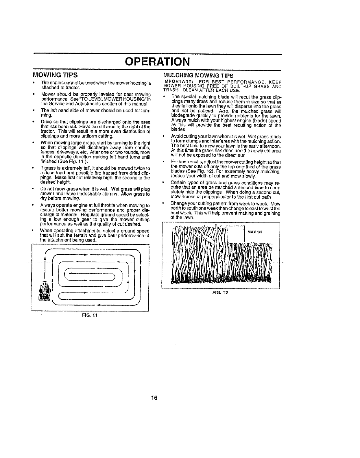
• When mowing fargo areas, start by turning to the right
so that clippings will discharge away lrom shrubs,
fences, driveways, etc. After one ortwo rounds, mow
tn the opposite direction makfng left hand turns untll
finished (See Fig. 11 )o
• If grass {s extremely tall, it should be mowed twice to
reduce toad and possible fire hazard from dded clip-
pings. Make first cut relatively high; the second to the
desired hefghto ,,
• Do not mow grass when it is wet. Wet grass wii}plug
mower end leave undesirable clumps° Allow grass to
dry tpefore mowing.
• Always operate engine at full throttle when mowing to *
assure better mowing perlormance and proper dis-
charge of material, Regulate ground speed by select*
ing a low enough gear to give the mower cutting
performance as well as the quality of cut des{i'edo
• When operating attachments, select a ground speed
that wi)l suit the terrain and give best performance of
the attachment being used_
f
'_,, , , _ __=J
IMPORTANT= FOR BEST PERFORMANCE, KEEP
MOWER HOUSING FREE OF {3UfLT-UP GRASS AND
TRASH CLEAN AFTER EACH USE.
° The special muEchlng blade will recul the grass clip*
pings many times and reduce them in size so that as
they fat! onto the lawn they will disperse into the grass
and not be noticed. Also, the mulched grass will
blodegrade quickly to provide nutrients for the lawn.
Aiways mulch with your highest engine (bfade) speed
as this wtfi provide the best recurring action of the
blades.
• Avoid cutting your lawn when ttiswet Wet grass tends
to form dumps and interferes with the mulching action.
The best time to mow your lawn is the early afternoon_
At this time the grass has dried and the newly cut area
wt{{ not be exposed to the dlrecf sun.
Forbest resutts, adjust the mower cutting height so that
the mower cuts off only the top one-third of the grass
blades (See Fig. 12). For extremely heavy mutohtng
reduce your w dth of cut and mow slowly
Certain types of grass and grass conditions may re-
quire that an area be mulched a second time to com-
pletely hide the clipplngs_ When doing a second cut,
mow across or perpendicular to the iirst cut path
Change your culling pattern from week to week. Mow
north to south one week then change to east to west the
next week. This will help prevent matting and graining
of the lawn_
MAX 113
FIG, 12
FIG, 11
16
CUSTOMER RESPONSIBILITIES
l_Ch_ng_mot_oIi_r_whonoO_r_((ng_n_ora h_o_ I_d ort_h)ghamb_o_lt_r_pQ_lvr_ll
e_S_l.Vt_morooI(_t__h_ll oper_t_r_Ir_dirtyo_d_f_Iy¢_ndiIIot_
3. I! oqulpp_dwilhoil(I)_or,_h[_eo o_owty 50 hours
4 ..Rep!scebladesm_e oi|enwhentoo, ,_fn_ndy so(L
GENERAL RECOMMENDATIONS
The warrartty on this tractor does not cover items that have ®
been subjected to operator abuse or negligence.. To
receive ful( value from the warranty, operator must maintain
tractor as (dstructed in this manual.
Some adjustments wIU need to be made periodica((y to
properly maintain your traclor.
AIt adjustments In the Service and Ad}ustmenls section of
this manual shou(d be checked at feast once each season..
,, Once a year you should replace the spark plug, clean
or replace air filter, and check blades and belts for
wear, A new spark p(ug and clean air filter assure
proper elf-fuel mixture and help your engine run better
andlast longer
®
BEARING ZERK
®
CLUTCH
PIVOT(S}
LUBRICATION CHART
®
•FRONT WHEEL (_)
BEARING ZERK
ENGINE (_
BEFORE EACH USE
• Check engine oillevel
" Check brake operation.
* Checktlre pressure,
• Check for loose fasteners,
(_ SAE 30 OR 10W30 MOTOR OIL
(_ GENERAL PURPOSE GREASE
(_ REFER'TO CUSTOMER RESPONSIB_LfflES "ENGINE" SECTION
IMPORTANT= DO NOT OIL OR GREASE THE PIVOT POINTE
WHICH HAVE SPECIAL NYLON BEARINGS VISCOUS, LUBR[
CANTS WiLL ATTRACT DUST AND DIRT THAT WILL SHORTEr'
THE L_FE OF THE SELF-LUBRICATING BEARINGS, IF YOL
FEEL THEY MUST BE LUBRICATED, USE ONLY A DRY, POW
17 DERED GRAPHITE TYPE LUBRICANT SPARINGLY
nl i II ,,i,
CUSTOMER RESPONSIBILITIES
,U,l,i ,in i i I I
TRACTOR
Always observe safety rules when performing any mainte-
nance
BRAKE OPERATION
If tractor requires more than six (6) feet stopping distance
at high speed in highest gear, then brake must be adjusted.
(See "TO ADJUST BRAKE" in the Service and Adjust-
ments section of this manual).
TIRES
• Maintain proper air pressure tn all tires (See "PROD.
UCT SPECIFICATIONS on page 3 of thIs manua]).
• Keep tires free of gasoline, otI, or insect control chemi-
cals which can hatm rubber.
. Avoid stumps, stones, deep ruts sharp objects and
other lazards that may cause tire damage
NOTE: To seal Itre punctures and prevent flal tires due to
slow leaks, lira sealant may be purchased from your local
parts dealer. Tire sealant also prevents tire dry rot and
corrosion, "
BLADE CARE
For best resuIts mower blades must be kept sharp_ Re-
place bent or damaged blades
BLADE REMOVAL (See Fig. 13)
• Raise mower to highest position to altcw access to
blades_
" Remove hex bolt, lock washer andtlat washer secudng
blade.
• Inslalr new or resherpened blade with trailing edge up
towards deck as shown
. • _FI.e.as_senj_bLehex .b_J, !ock washer and flat washer In
exact order as shown,.
• Tighten bolt securety (30-35 Ft.,Lbs torque),
fMPORTANT: BLADE BOLT JSGRADE 8 HEAT TREATED
NOTE: We do not recommend sharpening blade- but tfyou
do, be sure the blade is balanced.
BLADE MANDREL
TRAILING EDGE
HEX BOLT
(GRADE8}"_"_'"_-_'''_-1_
*AGRADEBHEATTREATEDBOLTCANBE
IDENTIFIEDBYSIXLINESONTHEBOLTHEAD,
FIG., I3
/
t8
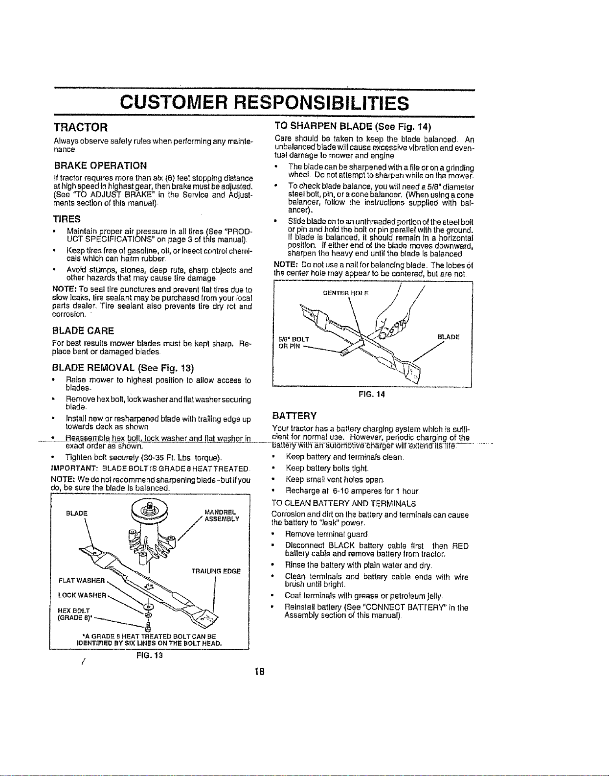
TO SHARPEN BLADE (See Fig. 14)
Care should be taken to keep the blade balanced An
unbalanced blade will cause excessive vibration and evem
tuaI damage 1o mower and engine
• The blade can be sharpened with a file or on a gdndhg
wheel. Do not attempt to sharpen while on the mower.
• To check blade balance, you wtf!need a 5/8" diameter
steel bolt, pin, or acone batancer, (When using a cone
balancer, follow the instrucltons supplied with bal-
ancer).
• Slide blade on to an unthreaded podion of the steel boil
or pln and hold the boff or pin parallel with the ground.
II btade is balanced, it should remain in a horizontal
position, ff either end of the blade moves downward,
sharpen the heavy end unltl the blade Is balanced
NOTE= Do not use a nail for balancing blade. The lobes ol
the center hale may appear to be centered, bul are not
OENTERHOL,E / /
BLADE
FIG,. 14
BATTERY
Your tractor has a baPery charging syslem which is suffi-
cient for normal use. However, periodic charging of the
b_dle_°W_th-_i1_bl_,_OtiV__h_Ygei =WEllexlerid it_ lif_; ............
• Keep battery and terminals clean.
• Keep battery bolts tight.
" Keep small vent holes open
• Recharge at 6-10 amperes for 1 hour
TO CLEAN BA'fTERY AND TERMINALS
Con:oslon and dirt on the batlery and terminals can cause
the battery to '%ak" power,
• Remove terminal guard
• Disconnect BLACK battery cable first then RED
batlery cable and remove battery from tractor,
• Rinse the battery with plain water and dry,
• Clean terminals and battery cable ends with wire
brush untiebright.
• Coat terminals wllh grease or petroleum jelly,
• Reinstall batlery (See "CONNECT BATTERY" in the
Assembly section of this manual)
CUSTOMER RESPONSIBILITIES
V_BELTS
Check V-bottsfordoteriorattonand wear after100 hoursof
operation and replace if necessary The botts are not
adjustable Replace belts If they begin toslip from wear,
TRANSAXLE COOLING
The fan and coot{rig fins of transmission should be kept
clean to assure proper cooling.
Do not attempt to c{ean fan or transmission while engine is
running or while the transmission is hot
• Inspect cooling fan to be sure fan blades are intact and
cfean
,, Inspect cooling fins for did, grass clippings and other
materials To prevent damage to seals, do not use
compressed air or high pressure sprayer to clean
coohng fins
TRANSAXLE PUMP FLUID
The transaxle was sealed at the factory and fluid mainte-
nance isnot required forths ltfe ofthe transaxle Should the
transax{e ever leak or require servicing, contact your near*
est authorized service center/departmenL
ENGINE
LUBRICATION
Only use high quality detergent oil rated with APt service
classification SF, SG, orSH Select the oil's SAE viscosity
grade according to your expected operating temperature,
SAEVISCOSITYGRADES
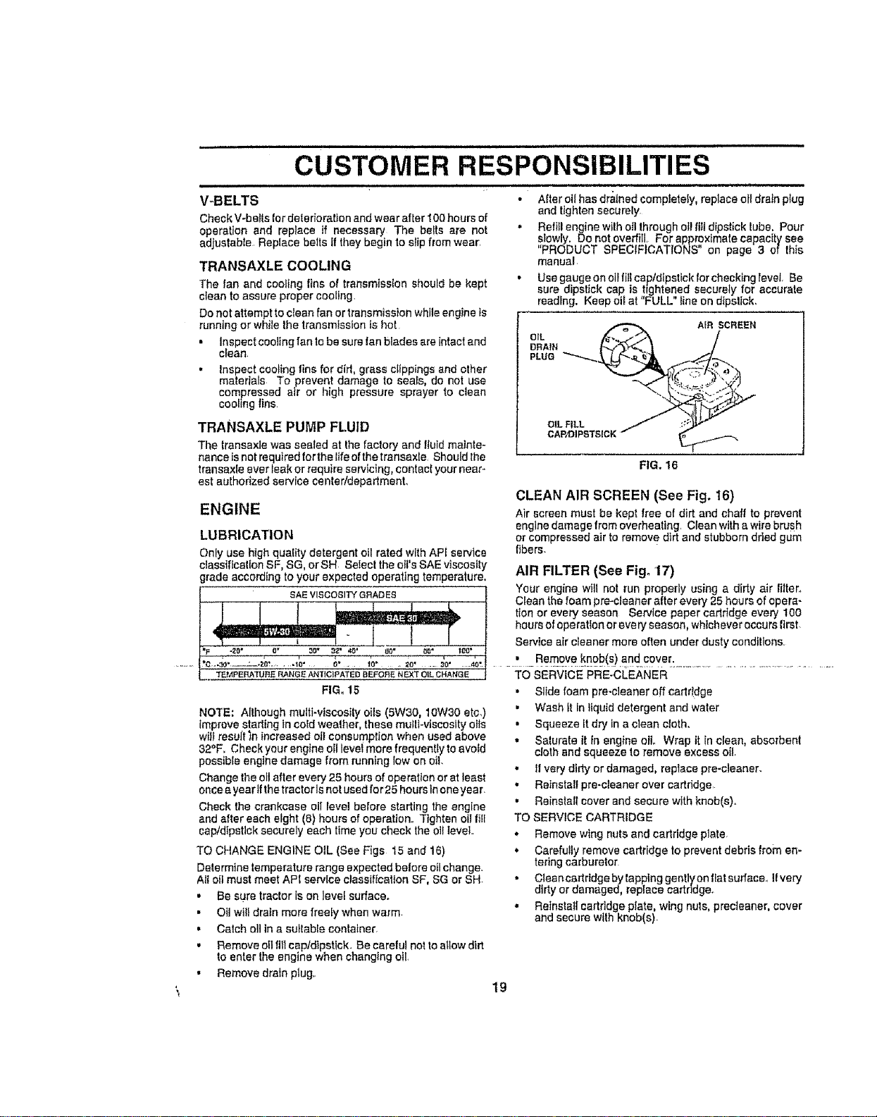
• After ot{has drained completely, replace ofl drain plug
and tighten securely
" Reffil engine with oil Ihrough otFftl! dipstick lube, Pour
s_owly. Do not overfill, Forapp_x_mate capacity see
PRODUCT SPECIFICATIONS on page 3 of this
manual
• Use gauge on oilfill cap/dipstick for checking level. Be
sure dipslick cap is tightened securely for accurate
reading. Keep olbat "FULL" line on dipstick,
OIL _ A}R SCREEN
,L,o
OILFILL
CAP,'DIPSTSICKt" _.._I..'_
FIG. 16
CLEAN AIR SCREEN (See Fig. 16)
Air screen must be kept free of dirt and chaff to prevent
englne damage from overheattngr Clean with awire brush
or compressed air to remov e dirt and stubborn dried gum
fibers.
AIR FILTER (See Fig. 17)
Your engine will not run properly using a dirty air lilter_
Clean the foam pro-cleanerafter every 25 hours of opera-
lion or every season Service papercartridge every I00
hoursof operationorevery season, whicheveroccurs first.
Service aircleaner more often underdusty conditions,
NOTE: Allhough multt-vtscosily oils (5W30, 10W30 eta,)
improve starting in cold weather, these mutli-viscosity oils
will result'in increased oil consumption when used above
32°F, Check your engine ofl level more frequently to avoid
possible engine damage from running low on oil.
Change the olt after every 25 houra of operation orat least
once a year tfthe tractor Is not used for 25 hours in one year.
Check the crankcase oil level before slatting the engine
and after each eight (8) hours of operation., Tighten oii fiEl
cap/dipstick securely each tfme you check the oil level,,
TO CHANGE ENGINE OIL (See Figs 15 and 16)
Determine temperature range expected before o{Ichange.
All oil must meet API service classification SF, SG or SH-
• Be sure tractor is on level sudace.
• Oil wiledrain more freely when warm,
• Catch ell in a sullable container,
• Remove oil flit cap/dipstlck. Be careful not to allow dirt
to enter the engine when changing oil,
• Remove drain plug,
TO SERVICE PRE-CLEANER
• Slide foam pro-cleaner off cartridge
• Wash tt in liquid detergent and water
• Squeeze it dry tn a clean cloth.
• Saturate it in engine oil Wrap it in clean, absorbent
cloth and squeeze to remove excess oil.
• 11very dirty or damaged, replace pre-cleaner.
• Relnstaltpre-cleanerover cartridge
• Reinstall cover and secure with knob(s).
TO SERVICE CARTRIDGE
,, Remove wlng nuts and cartridge plate,
, Carefully remove cartridge to prevent debris from en-
tering carburetor
• CleancartrtdgebylappinggentlyonfLatsurface., If very
dirty or damaged, replace cartridge.
• Reinstall cartridge pIate, wing nuts, precieaner, cover
and secure wtth knob(s)
!9
CUSTOMER RESPONSIBILITIES
= 11 H.HHH ,HN=
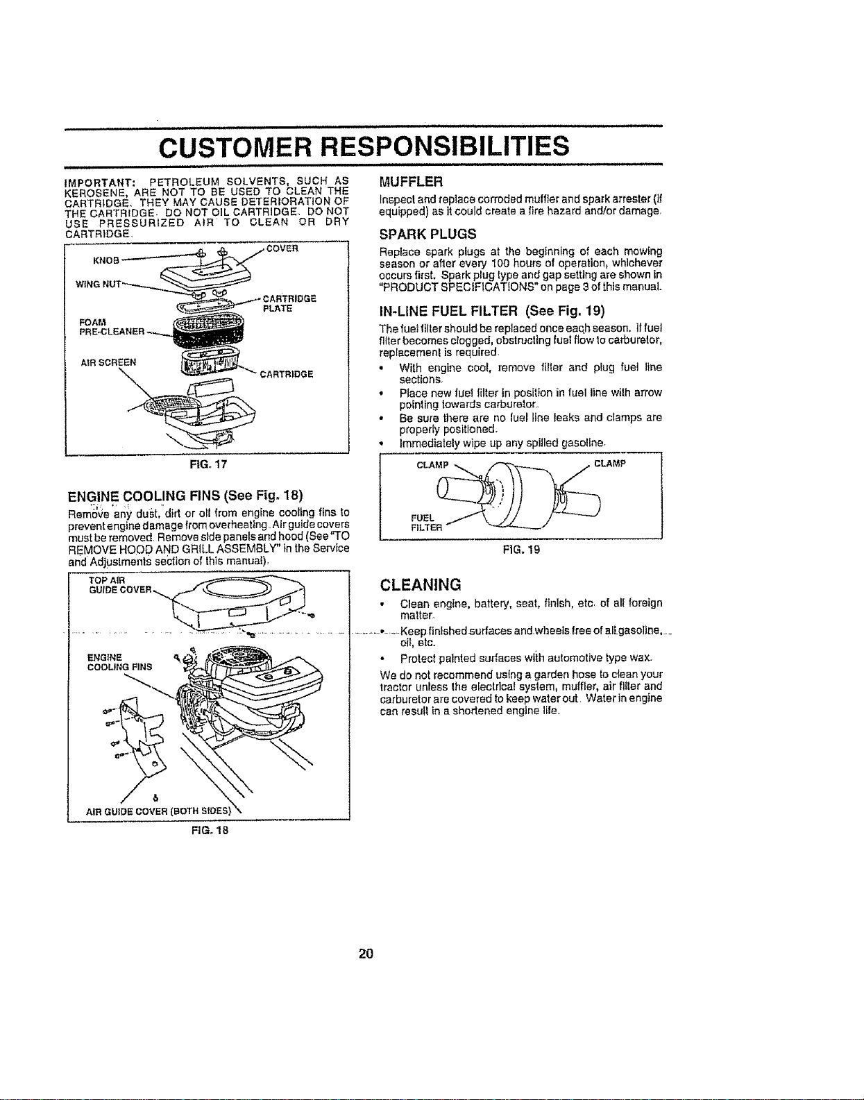
iMPORTANT: PETROLEUM SOLVENTS, SUCH AS
KEROSENE, ARE NOT TO BE USED TO CLEAN THE
CARTRtDGE_ THEY MAY CAUSE DETERIORATION OF
THE CARTRIDGE. DO NOT DIL CARTRIDGE, DO NOT
USE PRESSURIZED AIR TO CLEAN OR DRY
CARTRIDGE,
KNOB
FOAM
PLATE
AiR SCREEN
CARTRIDGE
FIGo17
ENGINE COOLING FINS (See Fig. 18)
Remove any dust, d rt or olf from engine cooling fine to
prevent engine damage from overheating. Air guide covers
"T
must be removed. Remove side panels and hood (See O
REMOVE HOOD AND GRILL ASSEMBLY" in the Service
and Adjuslments section of this manuat).
MUFFLER
Inspectandreplace corrodedmuffler andspark arreeter(if
equipped) as ]tcould create a fire hazard and/ordamage,
SPARK PLUGS
Replace spark plugs at the beginning of each mowing
season or after every 100 hours of operation, whichever
occurs first, Spark plug type and gap setting are shown in
"PRODUCT SPECiFICATiONS" on page 3 of this manual.
IN-LINE FUEL FILTER (See Fig, 19)
The fuel tiller should be replaced once eaqh season. ]ffuel
filter becomes clogged, obstructing rue! flow to carburetor,
replacement is required.
• With engine cool, remove filter and plug fuel tine
sections.
, Place new rue! filter in positton in luel line wilh arrow
pointing towards carburetor..
• Be sure there are no lueF line ieaks and clamps are
properly positioned.
Immediately wipe up any epilled gasoline,
FUEL /"f_\ t'lJ J'_-"-'-'--J
FILTER" "%/
FIG, 19
ENGINE _
AIR GUIDECOVER(BETH SLOES}\
CLEANING
• Clean engine, battery, seat, flnlsh, etc of all foreign
matter.
....... ,,--.-Keep flntshed surfaces and wbeeis Iree of all gasoline,_
oil, etc.
• Protect painted eurfeces wtih automotive type wax.
We do not recommend using a garden hose to clean your
tractor unless fhe electrical system, muffler, air filler and
carburetor are covered to keep water out Water in engine
can resul! in a ehortened engine Iile.
FIG. 18
2O
SERVICE AND ADJUSTMENTS
,,,,,,,,,, ii i, i
iiiiii1,111,1, i • , ii iii i ,,,i _L
CAUTION: BEFORE PERFORMING ANY SERVICE OR ADJUSTMENTS;
_i Depress clutch/brake pedal fully and set parking brake.
Place motion control lever in neutral (N) position,
Place attachment clutch in "DISENGAGED" posit|on.
- Turn ignition key "OFF" and remove key.
• Make sure the blades and al,i moving parts have completely stopped.
• Disconnect spark plug wire from spark plug and p,iace wire where it cannot come ,incontact
with plug.
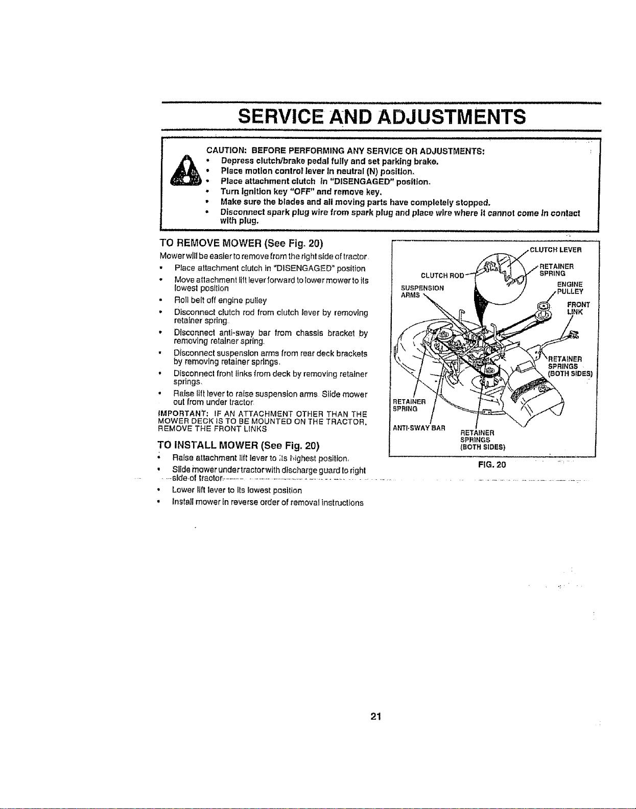
TO REMOVE MOWER (See Fig, 20)
Mowe rwl_l be Basle rtoremove from the right side of tractor
• Place attachment clutch in "DISENGAGED" position
• Move attachment lilt lever forward tolower mower to its
_owest posttion
', Roll belt off engine pulley
• Disconnect clutch rod from clutch Iever by removing
retainer spring
• Disconnect antFsway bar from chassis bracket by
removing retainer spring,
• Disconnect suspension arms from rear deck brackets
by removing retainer sprtngs,
• Disconnect front links from deck by removing retatner
springs.
• Raise tilt fever to false suspension arms Stide mower
out ,irom under lractor
iMPORTANT: IF AN ATTACHMENT OTHER THAN THE
MOWER DECK tS TO BE MOUNTED ON THE TRACTOR,
REMOVE THE FRONT LINKS
TO INSTALL MOWER (See Fig. 20)
; Ra{se attachment lift lever to ;_shighest posfflon,
• Slide mower undertractorwith discharge guardto right
.....side-of tractor- .................................................................
• Lower llft lover to its lowest position
• Install mower in reverse order of removalinstructtons
RETAINER
SPRING
ANTI-SWAYBAR
_INER
SPRING
ENGINE
FRONT
LINK
,111iiriii ii i
RETAINER
SPRINGS
(EOTHSIDES)
FIG. 20 ..... ='
21
SERVICE AND
i ,,,,,,,,,,, i, t, ,, 11111ii
TO LEVEL MOWER HOUSING
Adjust the mower while tractor lsparked on level ground or
driveway Make sure tires are properly inflated (See
"PRODUCT SPECIFICATIONS" on page 3of th s manual),
tf tires are over or underinflated, you will not properly adjust
your mower.
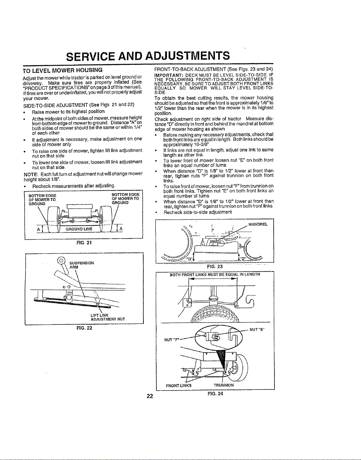
SIDE-TO-SIDE ADJUSTMENT (See Figs 21 and 22)
- Raise mower to Its highest postlion
• At the midpoint of both sides ot mower, measure he!g.ht
from bottom edge ol mowerto ground Distance A on
both aides o! mower Sh0utd be the same orwithin 1t4"
of each other
• If adjustment is necessary, make adjustment on one
side of mower only
* To raise one side of mower, lighten ti|t link adjustment
nut on that side
. To lower one side of mower, toosen lift tink adjustment
nut on that side,
NOTE: Each full turn of adjustment nut willchange mower
height about 1/8".
• Recheck measurements after adjusting
ADJUSTMENTS
nm ,1,, n
FRONT-TO-BACK ADJUSTMENT (See Figs, 23 and 24)
IMPORTANT: DECK MUST BE LEVEL SIDE-TO-SIDE, IF
THE FOLLOWING FRONT.TO-BACK ADJUSTMENT IS
NECESSARY, BE SURE TO ADJUST BOTH FRONT LINKS
EQUALLY SO MOWER WILL STAY LEVEL SIDE-TO-
SIDE,
TO obtain the best cutting results, the mower housing
should be adjusted so that the front ts approximalely 1/8" to
1/2 lower than the rear when the mower is in Its highest
position
Check adjustment on right side of tractor Measure dis.
lance "D" directly in front and behind the mandrel at bottom
edge of mower housing as shown
• Before making any necessary ad ustmants, checkthat
both front links are equalin length Both nks should be
approximately 10-3t8"
• If _lnks are not equal in length, adjust one link to same
length as other link
• To lower front of mower !oosen nut "E" on both front
links an equal number of lures
• When distance "D" fs 1/8" to t/2" lower at lront than
rear, tighten nuts "F" against trunnion on both front
links.
• To raise front of mower, loosen nut"F" from trunnion on
both front links, Tighten nut %" on both front links an
equal number ol turns
• When distance "D" is 1/8" to t/2" lower at front than
rear, tighten nul "F" against trunnion on both front links
• Recheck side4o-side adjustment
BOTTOMEDGE BOTTOMEDGE
OFMOWERTO OFMOWERTO
GROUND _. GROUND
LIFT LINK
ADJUSTMENT NUT
FIG. 21
SUSPENSION
ARM
FIG. 22
.--.,ce ) ., j MANDREL
....... FIG:, 23 ..................
BOTHFRONTLINKSMUSTBE EQUALINLENGTH
_:: .......... .._._%,
NUT *'E"
FRONT LINKS TRUNNION
22 FIG_ 24
SERVICE AND ADJUSTMENTS
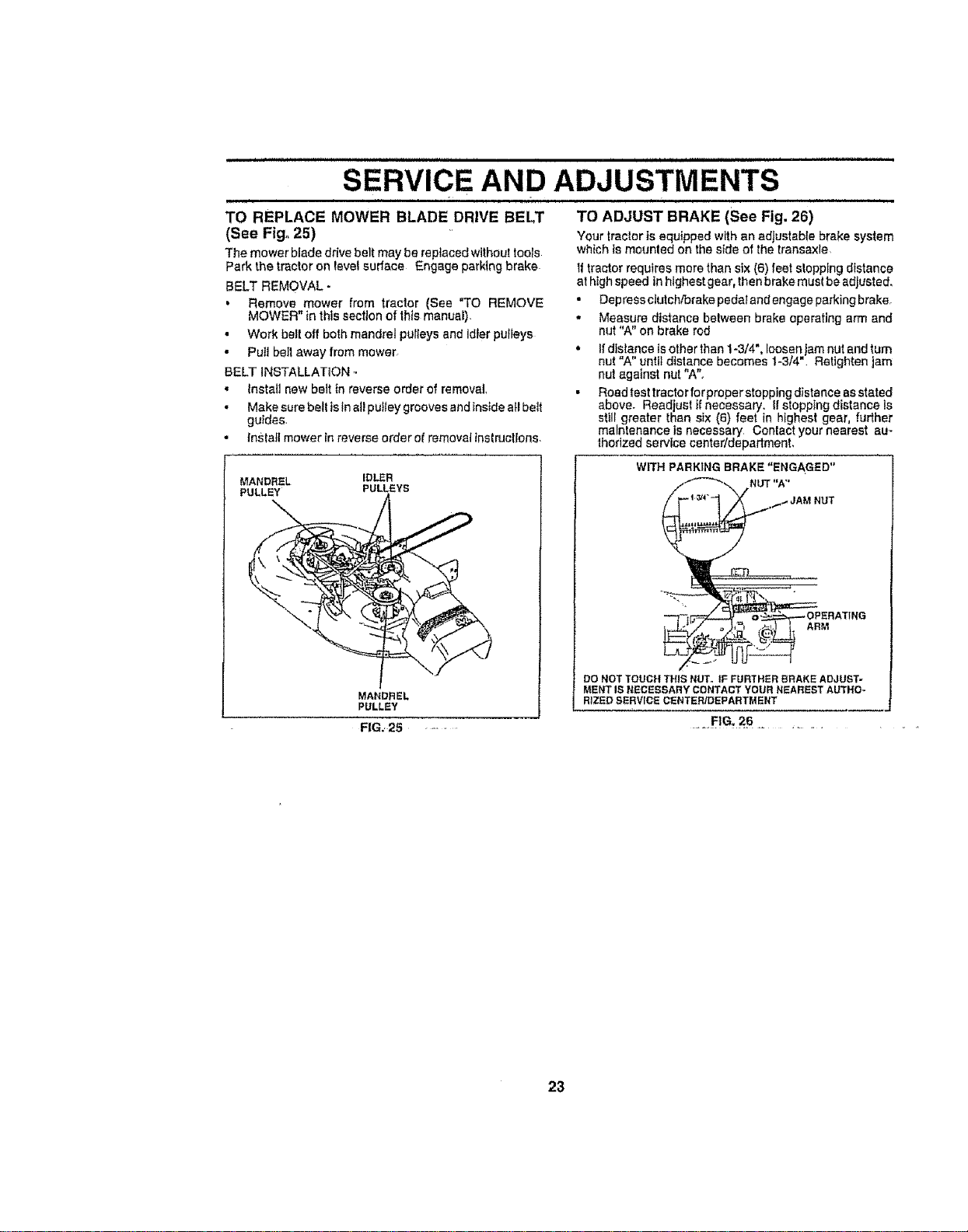
TO REPLACE MOWER BLADE DRIVE BELT
(See Fig. 25)
The mower blade drive belt may be replaced without tools
Park the tractor on level surface Engage parking brake
BELT REMOVAL -
, Remove mower from tractor (See "TO REMOVE
MOWER" in this section of this manual).
• Work belt off both mandrel pulleys and idler pufieys
• Pull belt away from mower.
BELT INSTALLATION
• tnstatl new belt in reverse order of removal
• Make sure belt isinnil puttey grooves and inside all belt
guides,
• install mower In reverse order of removal instructions,
MANDREL iDLER
PULLEY PULLEYS
MANDREL
PULLEY
FIG.. 25 ...........
TO ADJUST BRAKE (See Fig. 26)
Your tractor }s equipped with an adjustable brake system
which is mounted on the side of the transaxle
If tractor requtres more than six (6) feet stopping distance
at highspeed in highest gear, then brake must be adjusted.
• Depressclutchforakepedalandengageparkingbrake.
- Measure distance belween brake operating arm and
nut "A" on brake rod
,, Ifdistance isother than 1o3/4", loosen am nut and turn
nut Aunt d stance becomes 1-3/4 = Retighten am
nut against nut "A".
• Road test tractor for properstopping distance as stated
above- Read ust if necessary. If stopping distance ts
still greater than six (6) feet in highest gear, further
maintenance is necessary Contact your nearest au-
thorized service center/department,
WiTH PARKING BRAKE "ENGAGED"
NUT "A"
ARM
DO NOTTOUCHTHISNUT. tF FURTHERBRAKEADJUST-
MENTIS NECESSARYCONTACTYOURNEARESTAUTHO-
RIZEDSERVfCECENTER/DEPARTMENT
.__,..
23
SERVICE AND ADJUSTMENTS
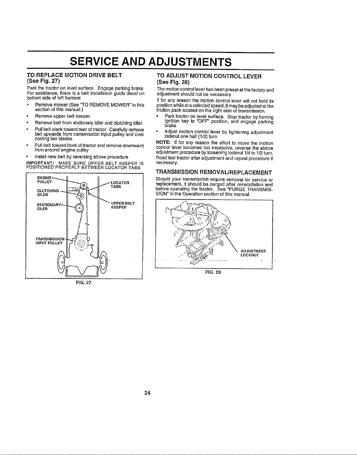
TO REPLACE MOTION DRIVE BEt.T
(SeeFig. 27)
Park the tractor on level surface. Engage parking brake
For assistance, there is a belt lnstatlatic, n guide decal on
botlom side of reftfootrest
, Remove mower (See "TO REMOVE MOWER" In this
section of Ibis manual.)
• Remove upper belt keeper,
• Remove belt from stationary idler and clutching idler.
- Pu+lbelt slack toward rear of tractor+ Carefully remove
belt upwards from transmission input pulley and over
cooling fan blades.
• Pull belt toward front of tractor and remove downward
from around engine pulley
• Instatl new belt by reversing above procedure
IMPORTANT: MAKE SURE UPPER BELT KEEPER tS
POSITIONED PROPERLY BETWEEN LOCATOR TABS,
ENGINE"_,-...,.,~
PULLEY
CLUTCHING ,.-,._
IDLER
STATIONARY"_
DLER
TRANSMISSiON-
INPUT PULLEY
0
.,.I"LOCATOR
*_TABS
UPPER BELT
KEEPER
TO ADJUST MOTION CONTROL LEVER
(See Fig. 28)
The motion controt lever has been preset at the factor'] and
adjustment should not be necessary
if for any reason the motion control lever wit+not hotd i s
position white at aselected speed, itmay be adjusted at the
fdclton pack leca{ed on the right side of transmission:
• Park tractor on level surface. Stop tractor by turn+ng
ignition key to "OFF" position, and engage parking
brake.
" Adjust motion control fever by tightening adjustment
tocknut one half (1./2) turn
NOTE: tf for any reason the effort to move the motion
controt lever becomes too excessive, reverse the above
adjustment procedure by _eosening Iocknut 1/4 to 1/2 turn.
Road test tractor after adjustmen! and repeat procedure ii
necessary.
TRANSMISSION REMOVAL/REPLACEMENT
Should your transmission require removal for service or
replacement, it should be purged after reinstallation and
before operating the tractor, Sea "PURGE TRANSMIS-
SION" f,nthe Operation section of this manual
ADJUSTMENT
LOCKNUT
FIG, 28
FIG+27
24
,, ,,,, ,L LLIL , I
SERVICE AND ADJUSTMENTS
TO ADJUST STEERING WHEEL ALIGNMENT
If Steedng wheel crossbars are not hodz0ntal (Ie!t to right)
when wheels are positioned siralght forward, remove steer-
ing wheel and reassemble perlnstrucflons Inthe Assembly
section of this manual.,
FRONT WHEEL TOE-IN/CAMBER
The front wheel toe-in and camber are not adjustable On
your tractor, if damage has occurred Io affect the front
wheel toe_In or camber, conlact your nearest authorized
service center/department.
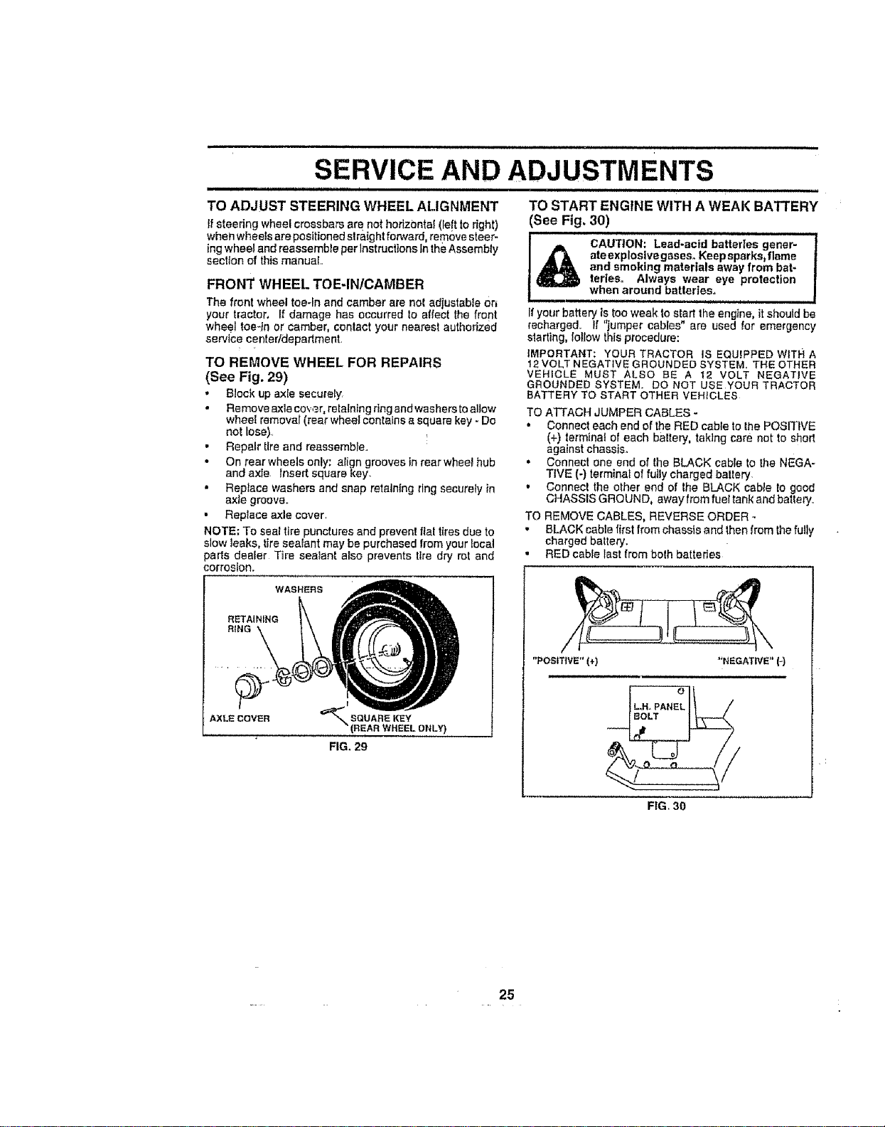
TO REMOVE WHEEL FOR REPAIRS
(See Fig. 29)
• Block Up axle secureSy,
,, Remove axleco,,;,_r, retaining ring and washersto alJow
wheel removal (rear wheel contains a square key - Do
net lose), !
. Repair tire and reassemble.
. On rear wheels only; align grooves in rear wheel hub
and axle. Insert square key.
• Replace washers and snap retainfng ring securely in
axte groove.
• Replace axle cover,
NOTE; To seal ttre punctures and prevent llal tires due to
slow leaks, tire sealant may be purchased from your Iocal
pads dealer Tire sealant also prevents lira dry rol and
cortes{on.
WASHERS
RETAINING
RING
AXLE COVER
_ SQUARE KEY
(REAR WHEEL ONLY)
FIG. 29
• ,JiJ.,. i , JI.L IL
TO START ENGINE WITH A WEAK BATrERY
(See Fig. 30)
J_IU U_ LLLL
1_ CAUTION" Lead-acid batteries goner- 1
ateexploslvegaseso Keepsparks,flame |
and smoking materials away from bat- |
teries. Always wear eye protection 1
, , , when around,, bat,]...,:.._.:t_',ri-,=............. mi
If your battery istoo weak to start the engine, it should be
recharged, If "jumper cables" are used for emergency
starting, fellow this procedure:
IMPORTANT; YOUR TRACTOR iS EQUIPPED WITH A
12VOLT NEGATIVE GROUNDED SYSTEM. THE OTHER
VEHICLE MUST ALSO BE A 12 VOLT NEGATIVE
GROUNDED SYSTEM. DO NOT USE YOUR TRACTOR
BATTERY TO START OTHER VEHICLES
TO ATTACH JUMPER CABLES -
• Connect each end of the RED cable to the POSITIVE
(+) terminal of each baitery, taking care not to short
against chassis,
• Connect one end of fhe E,LACK cable to the NEGA-
TIVE (-) terminal of fully charged battery,
• Connect the other end of Ihe BLACK came to good
CHASSIS GROUND, away tram fuel tank and battery.,
TO REMOVE CABLES, REVERSE ORDER -
• BLACK cable first from chassis and then (ram the fully
charged battery.
,, RED came last from boIh batteries
"POSITIVE" (+) "NEGATWE" (-)
,i
FIG, 30
25
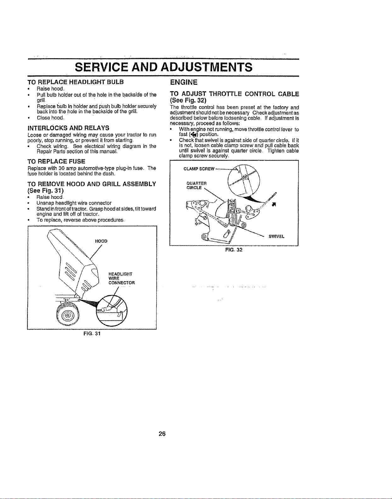
SERVICE AND ADJUSTMENTS
illlll llllll i ill i
ENGINE
TO REPLACE HEADLIGHT BULB
. Raise hood
• Putt bulb holder out of the hole in the backside of the
gdlt
• Reptace bulb In hoider and push bulb holder securely
back !nto the he e in the backside of the gdtL
. Close hood,
INTERLOCKS AND RELAYS
Looseor damaged wiringmay cause your tractorto run
poorly, stop running, or prevent it fromstarting
• Check wiring. See electrical wiring diagram in the
Repair Parts section of this manual.
TO REPLACE FUSE
Reptace with30 amp automotive-type plug-in fuse, The
fuse holder is locatedbehind the dash.
TO REMOVE HOOD AND GRILL ASSEMBLY
(See Fig. 31 )
• Ralsehood
• Unsnap headlight wire connector
- Standinfront oftractor, Grasp hoodatsides,tilttoward
engine and Itft off of tractor,
• To replace, reverse above procedures.
HOOD
HEADLIGHT
WIRE
CONNECTOR
TO ADJUST THROTTLE CONTROL CABLE
(See Fig. 32)
The throttle control has been preset at the factory and
adjuslment should not be necessary Check adjustment as
described below before loosening cable If adjustment iS
necessary, proceed as follows:
• With enqtne not running, move throttle control lever to
fast (,_ position.
, Check that swivel is against side of quarter circle. If tt
is not, loosen cable c_amp screw end pull cable back
until swivel is against quarter circle, Tighten cable
clamp screw securely,
QUARTER
CIRCLE
SWIVEL
FIG. 32
FIG. 31
26
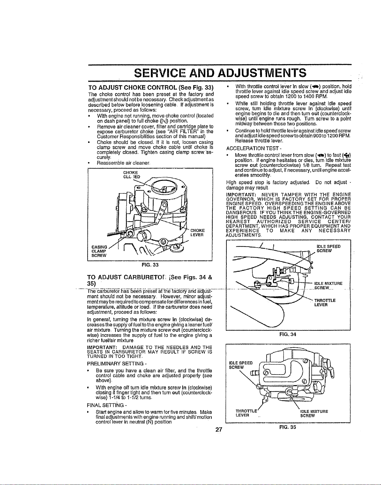
SERVICE AND
[HJHHH
TO ADJUST CHOKE CONTROL (See Fig. 33)
The choke control has been preset at the factory and
adjustment should not be necessary. Check adjustment as
described beiow before loosening cable. If adjustment is
necessary, proceed as follows:
= With engine not running, move choke control (located
on dash panel) to full choke (I\l) position.
, Remove air cleaner cover, fitter and cartridge plate to
expose carburetor Choke (sea "AIR FILTER'In the
Customer Responsibilities section of this manual)
,, Choke should be closed. If it is not, loosen casing
clamp screw and move choke cable untiI choke Is
coml_letely closed.. Tighten casing clamp screw se-
cure,y.
• Reassemble air cleaner.
CASING
CLAMP
SCREW
" CHOKE
LEVER
i ii i ii ii iiii iiiiiiiiiiiiiiiiiiiiihllllll
ADJUSTMENTS
• W_th throttle control lever in slow (_,m,) position, hold
throttle lever against idle speed screw and adfust idle
speed screw to obtain 1200 to 1400 RPM.
• While still holding throttle lever against Idle speed
screw, turn Idle mixture screw In {clockwise) unlll
engine begins to die and then turn out (counterclock-
wise) until engine runs rough, Turn screw to a point
mldway between those two positions.
• Continue to hold throttle teveragalnst _diespeed screw
and adjust idle speed screw to obtain 900 to 1200 RPM
Release throttle lever.
ACCELERATION TEST -.
,, Move throttle control ]ever from stow (qe_) to fast (,_)
position. _fengine hesitates or dies, turn idle mixture
screw out (counterclockwise) 1/8 turn. Repeat test
and continue to adiust, if necessary, until engine accel-
erates smoothly.
High speed stop is factory adjusted. Do net adjust -
damage may result
IMPORTANT: NEVER TAMPER WiTH THE ENGINE
GOVERNOR, WHICH IS FACTORY SET FOR PROPER
ENGINE SPEED. OVERSPEEDING THE ENGINE ABOVE
THE FACTORY HIGH SPEED SETTING CAN BE
DANGEROUS IF YOU THINK THE ENGINE*GOVERNED
HIGH SPEED NEEDS ADJUSTING, CONTACT YOUR
NEAREST 'AUTHORIZED SERVICE CENTER/
DEPARTMENT, WHICH HAS PROPER EQUIPMENT AND
EXPERIENCE TO MAKE ANY NECESSARY
ADJUSTMENTS.
FiGo 33
TO ADJUST CARBURETOri iSee Figs_ 34 &
35)
merit should not be necessary However, minor adjust-
me ntmay be required to co mpensate for differences infuel,
lemperature, altitude or toad. If the carburetor does need
adjustment, proceed as follows:
In generar, tuming the mixture screw tn (cieckwtse) de-
creases the supply of fuel to the engine giving a teaner fueV
air mixture. Turning' the mixture screw out (counterclock-
wise) increases the supply of fueE to the eng}ne giving a
dcher fueVatr mixture
IMPORTANT: DAMAGE TO THE NEEDLES AND THE
SEATS iN CARBURETOR MAY RESULT IF SCREW IS
TURNED IN TOO TIGHT.
PRELIMENARY SETTING -
• Be sure you have a clean air filter, and the throttle
control cable and choke are adjusted propedy (see
above)
• With engine off turn idle mtxP.Jrescrew in (c_ockwise)
dosing it finger tight and then turn out (counterclock-
wise) 1-'t/4 to 1-112 turns.
FINAL SETTING -
, Start sngfne and allow to warm for five minutes. Make
ftnaEadJustme his withengine running and shift/motion
control lever in neutral (N) position
....... SCREW_=_
IDLE SPEED
SCREW
FIG. 34
_DLESPEED
SCREW
LEVER
THROTTLE IDLE MIXTURE
LEVER SCREW
27 FIG. 35
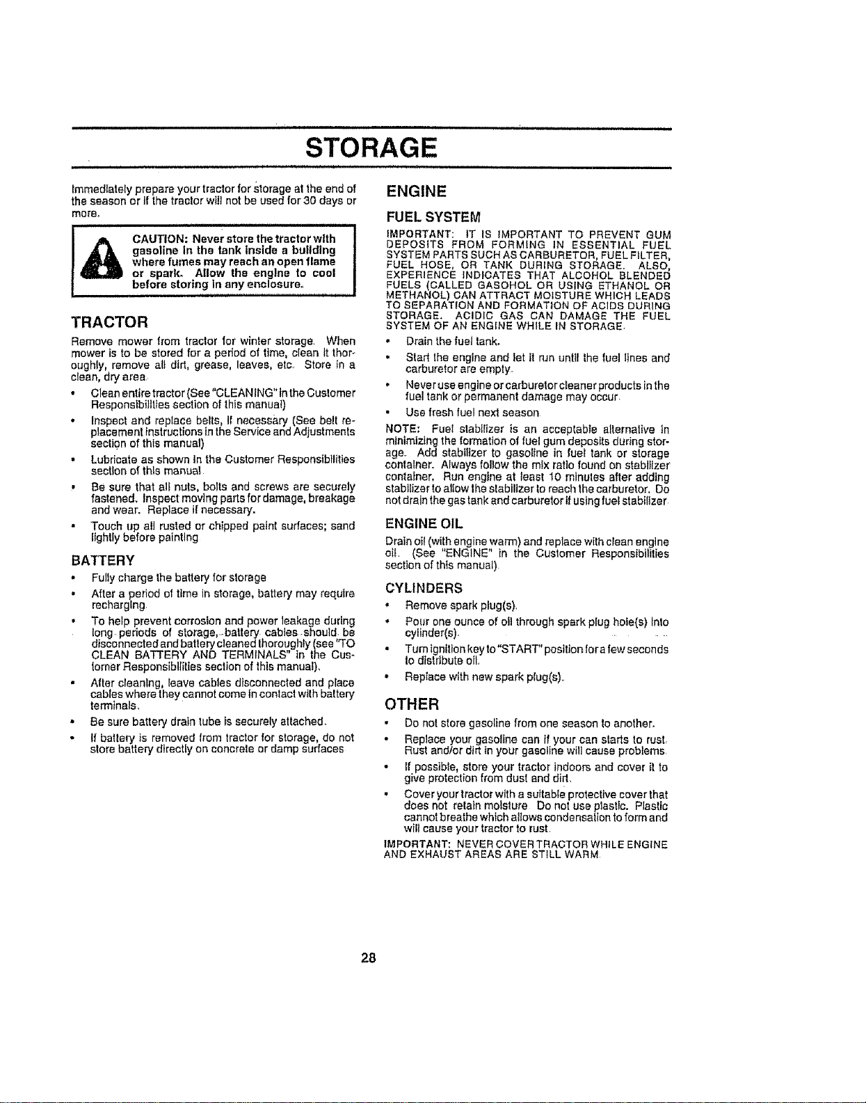
Ji un i .................
STORAGE
immediately prepare your tractor for storage at the end of ENGINE
the season or if the traclor will not be used for 30 days or
more.
CAUTION: Never store the tractor with
gasoline In the tank inside a building
where fumes may reach an open flame
or spark. Allow the engine to cool
before storing in any enclosure.
TRACTOR
Remove mower from tractor for winter storage When
mower is to be stored for a pedod of time, clean It thor_
oughly, remove all dirt, grease, leaves, etc Store tn a
clean, dry area
• Clean entire tractor (See"CLEANING"tn the Customer
Responsibilities section of this manual)
• inspect and replace belts, It necessary (See belt re-
placement instructions inthe Service and Adjustments
section of this manual)
• Lubricate as shown in the Customer Responsibilities
section of this manua!
• Be sure that alt nuts, bolts and screws are securely
fastened. Inspect moving parts for damage, breakage
and wear Replace if necessary.
• Touch up all rusted or chipped paint surfaces; sand
fightly before painting
BATTERY
• Fully charge the battery for storage
• After a period el time in storage, battery may require
recharging
, To help prevent corrosion and power leakage during
Iong periods of storage, battery cables should be
disconnected and battery cleaned Ihoroughly (see 'qo
CLEAN BATTERY AND TERMINALS" in the Cus-
tomer Responsibilities section of this manual)
" After cleaning, _eave cables disconnected and place
cables where they cannot come in contact wllh battery
terminals,
• Be sure battery drain tube is securely attached
• tf battery is removed from tractor for storage, do not
store battery directly on concrete or damp surfaces
FUEL SYSTEM
iMPORTANT: tT IS IMPORTANT TO PREVENT GUM
DEPOSITS FROM FORMING IN ESSENTIAL FUEL
SYSTEM PARTS SUCH AS CARBURETOR, FUEL FILTER,
FUEL HOSE, OR TANK DURING STORAGE. ALSO,
EXPERIENCE INDICATES THAT ALCOHOL BLENDED
FUELS (CALLED GASOHOL OR USING ETHANOL OR
METHANOL) CAN ATTRACT MOISTURE WHICH LEADS
TO SEPARATION AND FORMATION OF ACIDS DURING
STORAGE ACIDIC GAS CAN DAMAGE THE FUEL
SYSTEM OF AN ENGINE WHILE IN STORAGE
• Drain the fuel tank
• Start the engine and let it run until the fuel fines and
carburetor are empty.
• Never use engine or carburetor cleaner products in the
fuel tank or permanent damage may occur
• Use fresh fuel next season
NOTE; Fue! alabtlizer is an acceplable alternative in
minimizing the formation of fuel gum deposits during stor-
age Add stabilizer to gasoline in fuel tank or storage
container Always fol!ow the mix ratio found on stabilizer
container, Run engine at least t0 minutes after adding
stabilizer toallow the slabiltzer to reach the carburetor. Do
not drain the gas tank and carburetor if using fuel stabilizer
ENGINE OIL
Drainoi_(with enginewarm) and replace wilh clean engine
oil (See "ENGINE" in the Customer Responsibilities
sectton of this manual)
CYLINDERS
, Remove spark plug(s),
• Pour one ounce of oil through spark plug hole(s) Into
cylinder(s).
. Turn tgn{t_onkeyto"START"posttion fore few seconds
Io distribute oil
• Replace with new spark plug(e),
OTHER
• De not store gasoline from one season to another.
• Replace your gasoline can if your can slarts to rust
Rust and/or dirt in your gasoline will cause problems
• If possible, store your tractor indoors and cover it to
give protection from dust and dirt
• Cover your tractor with a suttabfe protective cover that
does not retain moisture Do not use plastic Plastic
cannot breathe which allows condensation to form and
will cause your tractor to rust
IMPORTANT: NEVER COVERTRACTOR WHILE ENGINE
AND EXHAUST AREAS ARE STILL WARM
28

PROBLEM
=,
Wgl not start
Hard to start
Engfne wlfl not turn over
Engine Clicks but will not
start
Excessfvs vibration
TROUBLESHOOTING POINTS
JJu,,,,,,, , =,, =, ,,,,,H,H, H ,,= L HH_,,H,H,, =
CAUSE CORRECTION
1 Out of fuel
2 Engine nat =CHOKED" prepetty
3 Engine flooded
4 Bad sparkpfug
5 Dirty air titter
6 Dirty fuel filter
7, Wafer tn fuel
B Loses ordamaged widng
g_ Carburatar out at adtus!ment
10 Engine vefvsa out of adjuslment
I. Didy Wr Ifitar
2 Bed spark plug
3 Week of dead battery
4 Dirty fuel filler
5. Stale or ditty fuel.
6 Loose or damaged widng
7 CarbureforoUt (if adjustment
B Englae vWvea out of ad|uslmant
CIufch._)rakepedWnot depressed
2. Attachment clutch is engaged.
3, Weak ordead battery
4 BJown fuse
5, Corrodedbatter/terminals
6. Loose ar damaged wiring
Faulty IgnitionSwilch
8 Faulty soianold of starter
9 Faulty operator presence swtleh(es)
1, Weakerdeed baJfery.
2,. Corroded battery terminals.
3. Leone or ds,megad wiring
4 FBuIF]sa[eneid ar starter
,,,=
1 Cuttingtoe much grass/too fast
2 Throttle tn "CHOKE" poslgono
3 Bufid-upof grass, leaves and flash under mower
4 Ditty air lilfar
5 Law aft fnvWldfrty el!
6 Faulty spark plug
7 Dirty fueffliter
8 Stale or dirty fuel
g Water Infuel
tO Spa_ plug wira lease.
'I1 Dirty engine airscraenlfine,
12 Dirty/clogged mt.fffler
13 Louseor damaged wklng
14 Cmburefer outof adiustment
15 Engine valves out of adjustment
Worn, bent or loose binds
2 Bent blade mandrel
3 Looseldamagad part(s)
1 FIllfuel tank
2. Sen "TO START ENGINE InOperation section.
3 Wait several mlnules bafara attempting to start
4 Replace sparkplug.
5 Ctsan/rap{acsair filter.
6 Replacefuel triter
7 Drain fuel_ankand carburetor, refill lank with fresh
gasoline and replace fuel filter,
8 Cheek allwidng,
9 See "To Adjust Carburetor" in Service Adjustments
section.
t0 Conlast an authorized service canter/dopartmont.
1 Cleedrepleae air tilter
2. Replace sparkplug
3 Recharge or replace bntlery
4 Replace fuelfiller
5 Drain feet tank and refillwithfresh gasoline
6 Check el! wiring,
7 Sea "To Adjust Carburalor" In Sarv[ce Adjustments
section.
B Contact an authorized service canfetldepattmant.
t Depress cfutsW_rake pedal
2, Disengage nttachmsni clutch
3, Recharge or raptsca botter_,,
4 Raplasa fusn
5 Clean batiery fem_tnels
g Check all wiring
7 Check/replace Ignition swt[ch
8 Check/replace solenoid orstarter
9 Contactan authorized serViceeenfaddepadmenL
t Racha_geormplBeebattery
2 Clean battery terminals .
3, Check ag wiring
4 Check/replace sofaneid orsfader
f. Set In*'Higher Cut_position/reduce speed
2 Adjust {hmttiaceniml
S Clean underside of mov,-erhousing
4 Clean/replace alr filler
5, Checkellleve!/changa off.
6. Clean and regap or change spark plug
7 Replace fuel tiller.
g Drain tue_lank and retitt wtih fresh gasoline
g Drata fue_tank and carburetor, r_flllfankWlthflash
gasoline end replace feet filter
10 Cennecl and tighten spark plug wire
11 Clean nngino airscree_fins
!2 Clean/replace muffler.
t3 Check all wldng.
14 Bee "To Adjust Carburelor" tnService Adjustments
section.
15 Contact an authorized service confer/department
HH,,H,,N '
Replace brads Tighten blade bolt
2 Replace blade mandrel.
3 Tighten ]Does perils) Replace damaged parts
29

TROUBLESHOOTING POINTS
PROBLEM CORRECTION
Engine continues to run
when operator leaves Seat
with attachment clutch
engaged
poor_ul_uneveN
Mower blades wig not
rotate
Poor grasa discharge
Headlight(s) not working
(if so equTpped)
Ballery wig not ohaTge
Leas of drive
Engine "backfires"
when tub-nineengine
"OFF"
'CAUSE
l, Faultyoperator,safetypresencecenirolsyslem
i,n ,,/ ii ,
I Worn, bent or loose blade
2 Mower deck not level
3 Buildup of graee_laavee_end trash under mower
4. Benl blademandrel,
5 Cloggedmowardeck vanlholesfi'ombuildupof
grass, leaves, and lrash around mandrets
1. Obslrucgon in cluleh mechenlsm
2 Wor_damagad mower ddve belL
3, Frozen Idlerpulley
4 Frozen blade mandrel
I Engine speed too slow_
2. Travel speed too feet
3 Wet grass
4. Mower deck not level
5, Low/uneven fire air pressure
6, Worn, benl or loose b_eda
7 BUildup of grass, leaves and trash under mower
g. Mower ddva belt worn
g BladesImpropedylnst_lad
10 Improper blades used
1t Cloggedmower deck vent holes from buttdup o!
grass= leaves, and t_sh around mandrels
t Switch is "OFF"
2 Bufb(s) burned OlJlr
3 Faul|y light _vilch
4 Loose ordamaged wiring
5 -BIewnfusa
t Bed bailer/coil(s}
2. Poor sable connectlons
3 Faulty regulator (it _o equipped)
Faultyademetor
1 Freewheel eontro_In"disengaged"po_ilJono
2 Motion dr_vebait worn, damaged, or broken
3. Alr trapped Jntmnemlssl0nduring shipment
or servicing
,[,u, uu
1 Engine fhmlllecenlmlnot set at "SLOW _
poslIJon for 30 seconds before sloppingengine,
1 Check wiring, swltchas and connections If not
corrected, contact an eulhorlzodservice cenlerl
dspadmenl
• ,,,,,,,, ,,,
i Replaceblade Tighten bladebolt
2 Lavet mower desk
3 Clean underside of mower housing,
4 Replace bladamandrel,
5 Clean around mandrels Io open yen| holes
f Remove obslruction
2, Replace mower drive bolt
3 Replace Id_erpulley
4 Replace blademandrel
_r Place thmlge controlIn "FAST _position
2 Shiftto slowerspeed.
3 Allow grassto dr/before mowing
4 Levelmower deck
5 Check liras forproper airpressure,
6 Repteoe/shacpenblade Tighten blade bolt
7 Ctaan underside of mower houstng
g Replace mower ddve bell
g RelnetaIIblades sheep edge down
t0 Replace with bladesgated tn this manual
1 I. Clean around mandrals 1oopen vent holes
1 Turn swltch "ON",
2 Replace bulb(s)
3. Checldreplaea light awilch
4 Check wldng and connections
5 Replace fuse:
Replace bmtsry
2 ChecWclean allconnections
3 Replace regulator
4 Replace atlemabr
...m , , ,
I Placelrsewheel conlrolIn "engaged" posilIon
2. Replace motion drive belt
3,, Purge Itansmlssfun
1 Move lhrollfa controlto "SLaVe" positionand etfow
Io Idle for 30 seconds balers slopping engine
30
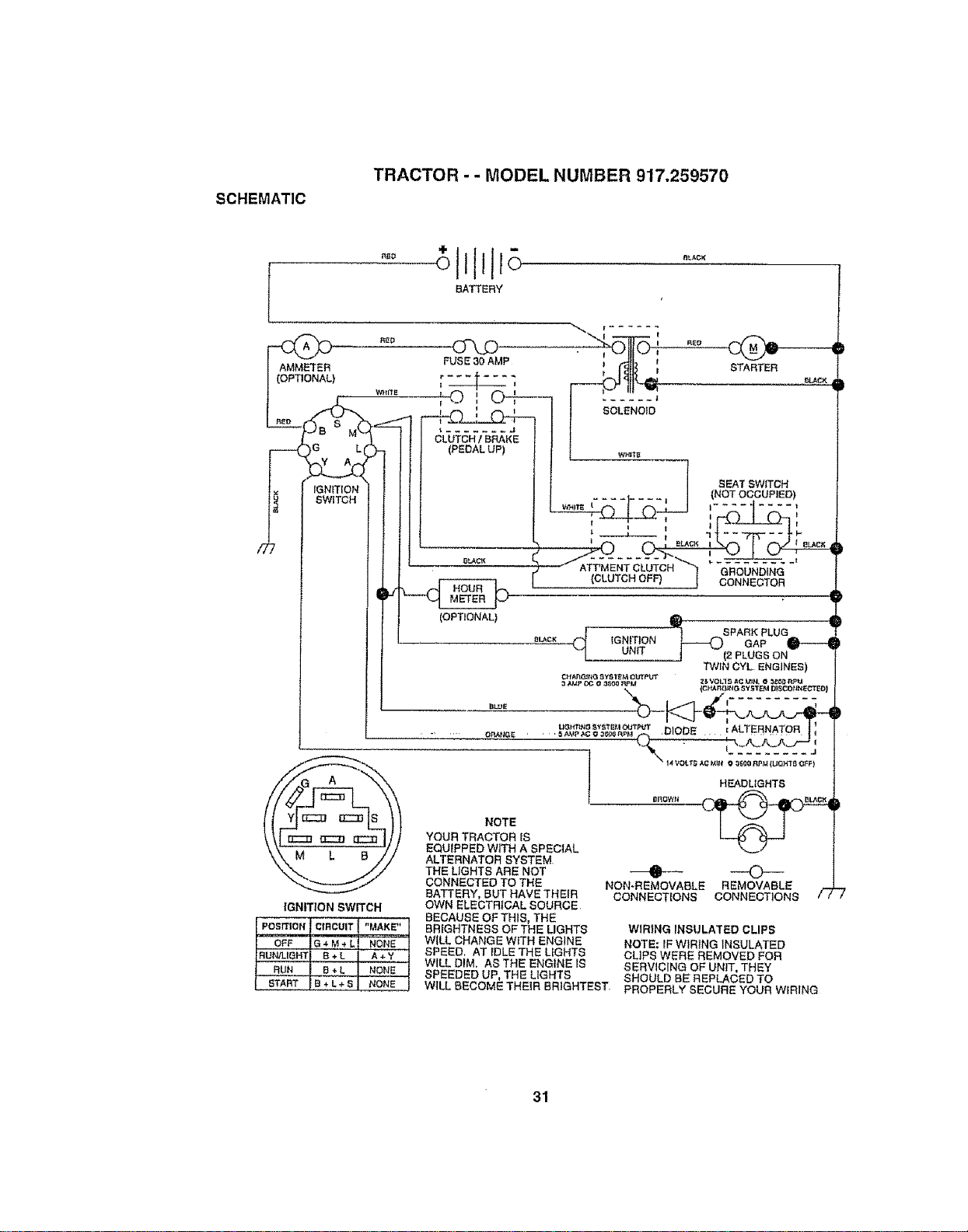
SCHEMATIC
TRACTOR - - MODEL NUMBER 917.259570
[
tGNmON
SWITCH
BATTERY
(GNITION SWITCH
POSITION CIRCUIT "MAKE"
OFF G ÷ M + L NONE
RUN/LIGHT B + L A + Y
RUN B + L NONE
START B + L + S HONE
NOTE
YOUR TRACTOR [S
EQU(PPED WITH A SPECfAL
ALTERNATOR SYSTEM
THE UGHTS ARE NOT
CONNECTED TO THE
BATTERY, BUT HAVE THEIR
OWN ELECTRICAL SOURCE
BECAUSE OF THIS, THE
BRIGHTNESS OF THE LIGHTS
WILL CHANGE WITH ENGINE
SPEED, AT IDLE THE LIGHTS
WILL DIM, AS THE ENGINE IS
SPEEDED UP, THE LIGHTS
SEAT SWITCH
(NOT OCCUPIED)
HEADLIGHTS
• O
NON-REMOVABLE REMOVABLE
CONNECTIONS CONNECTIONS
WIRING INSULA'rED CLIPS
NOTE: IF WIRING INSULATED
CLIPS WERE REMOVED FOR
SERVICING OF UNIT, THEY
SHOULD BE REPLACED TO
WILL BECOME THEIR BRIGHTEST, PROPERLY SECURE YOUR WIRING
31

REPAIR PARTS
TRACTOR - - MODEL NUMBER 9i7.259570
ELECTRICAL
12
26
25
7
32
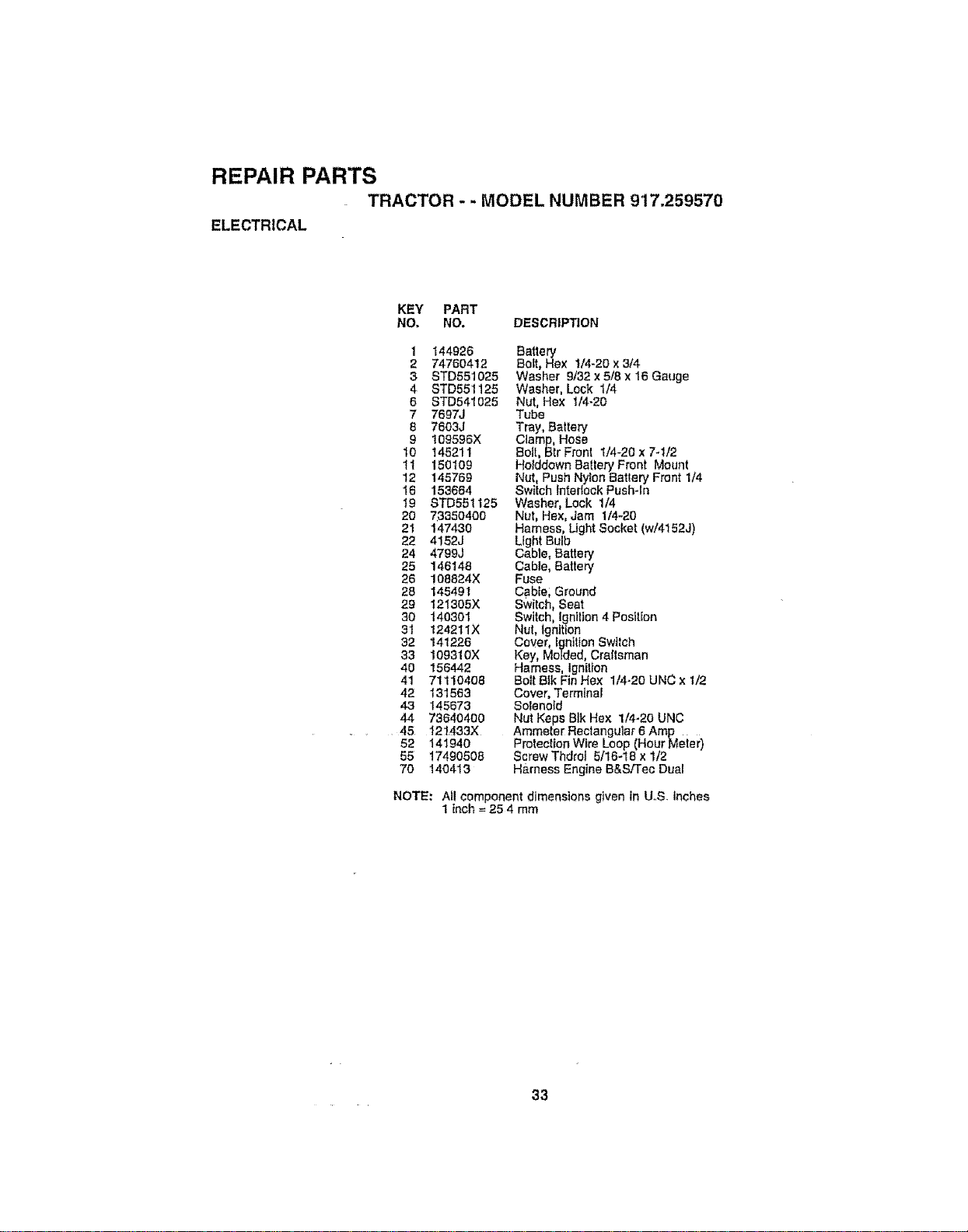
REPAIR PARTS
TRACTOR - - MODEL NUMBER 9'17.259570
ELECTRICAL
KEY PART
NO. NO. DESCRIP_ON
1 144926 Battery
2 74760412 Bolt, Hex 1/4-20 x 3/4
3 STD551025 Washer 9/32 x 5/8 x 16 Gauge
4 STD551125 Washer, Lock I/4
6 STD541025 Nut, Hex 1/4-20
7 7697J Tube
8 7603J Tray, Battery
9 t09595X C!arnp, Hose
t0 145211 Bolt, Btr Front 1/4-20 x 7-I/2
11 150109 Holddown Battery Front Mount
12 145769 Nut, Push Ny!on Batlery Front 1/4
16 153664 Switch Interlock Push-In
19 STD551125 Washer, Lock 1/4
20 73350400 Nut, Hex, Jam 1/4-20
21 147430 Harness, Light Socket (w/4152J)
22 4152J Light Bulb
24 4799J Cable, Battery
25 146148 Cable, Battery
26 108824X Fuse
28 145491 Cable; Ground
29 121305X Switch, Seat
30 140301 Switch, ignition 4 PosltEon
31 1242tlX Nut, Ignition
32 141226 Cover, ignition Switch
33 109310X Key Molded, Craftsman
40 156442 Harness, Ignition
41 711!0408 Bolt Blk Fin Hex 1/4-20 UNC x 1/2
42 t31563 Cover, Terrninal
43 145673 Soteno|d
44 736,10400 Nut Keps BIk Hex 1/4-20 UNC
45 i21433X Ammeter Rectangular 0Amp ....
52 141940 Protection Wire Loop (Hour Meter)
55 17490508 ScrewThdrol 5116-18 x 1t2
70 140413 Harness Engine B&s.rrec Dual
NOTE: Atl component dimensions given In U°S. inches
1 Inch = 25 4 mm
33
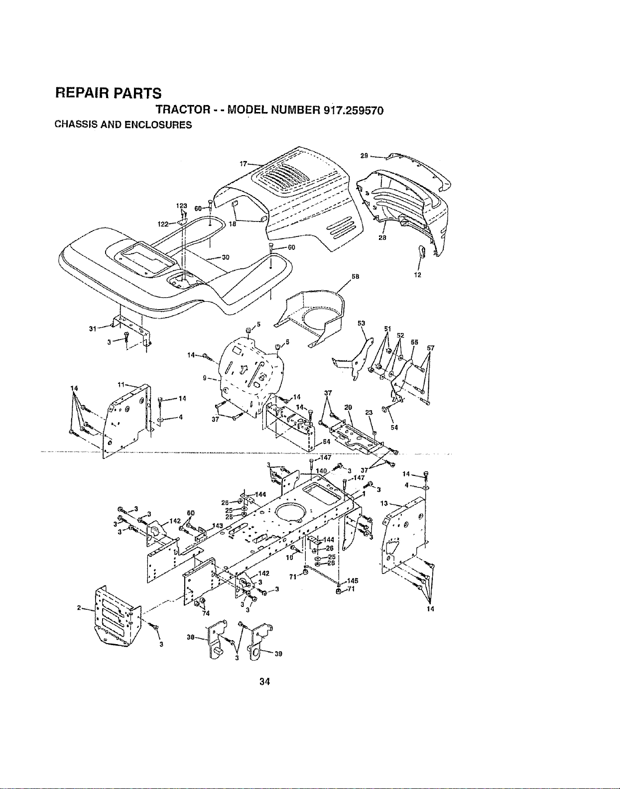
REPAIR PARTS
TRACTOR - - MODEL NUMBER 917;259570
CHASSIS AND ENCLOSURES
14
3
3
53
37
54
14
34
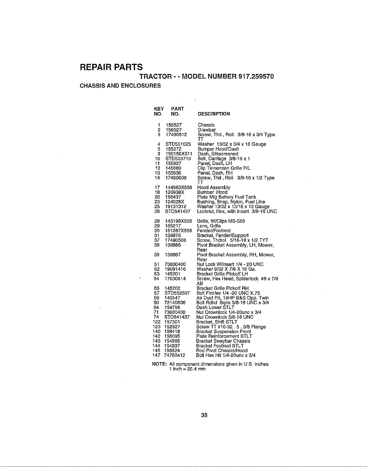
REPAIR PARTS
TRACTOR -" MODEL NUMBER 9'17.259570
CHASSIS AND ENCLOSURES
KEY PART
NOr NO. DESCRIPTION
1 159527
2 159527
3 17490612
4 STD551025
5 155272
9 150156X011
10 STD533710
11 155927
t2 145660
13 155938
14 17490608
17 144983X558
18 126938X
20 156437
23 124028X
25 19131312
26 STD541437
Chassis
Drawbar
Screw, Th'J., Roll 3/8-t6 x 3/4 Type
13+
Washer !3/32 x 3/4 x 16 Gauge
Bumper Hoo_Dash
Dash, SItkscreened
Bolt, Carriage 3/8-16 x 1
Panel, Dash, LH
Clip Tinnerman Grt!ie P/L
Panel+ Dash. RH
Screw, Thd, Roll 3/8-16 x 1/2 Type
Tr
Hood Assembly
Bumber Hood
Plate Mtg Battery Fuel Tank
Bushlng, Snap, Nylon, Fuel Line
Washer 13/32 x 13/16 x 12 Gauge
Locknut, He×, with Insert 3/8-16 UNC
28 145t98X558
29 155217
30 15t287X556
31 139976
37 174905o8
38 139886
39 139887
51 73800400
62 19091416
53 145201
54 17030814
55 145202
57 STD552507
58 140547
60 72140606
64 154796
71 73680400
74 STD5414.37
122 157301
I23 152927
140 156418
t42 156095
143 154966
144 154207
145 156524
147 74760412
Gdlte, W/Clips MS-558
Lens, Grille
Fender/Footrest
Bracket, Fender/Support
Screw, ThdroL 5/16-t8 x 1/2 TYT
Pivot Bracket Assembly, LH, Mower,
Rear
Pivot Bracket Assembly, RN, Mower,
Rear
Nut Lock W/Insert 1/4 - 20 UNC
Washer 9/32 X 7/8 X t6 Gao
Bracket Grille P{ckoff LH
Screw, Hex Head; Splderlock #8 x7/8
AB
Bracket Grille Pfckoff RH
Bolt FinHex 1/4 -20 UNC X.75
Air Duct PtL 18HP B&S Opp. Twin
Bolt Rdhd Sqnk 3t8-16 UNC x 3/4
Dash Lower STLT
Nut Crownlock 1/4-20unc x 3/4
Nut Crownlock 3/8-16 UNC
Bracket, Shift STLT
Screw TT #10-32.5.3/8 Flange
Bracket Suspension Front
Pfate Reinforcement STLT
Bracket Swaybar Chassis
Bracket Footrest STLT
Rod Pivot ChasslstHood
Bott Hex Hd 1/4-20unc x 3/4
NOTE; All component dimensions given in U S inches
1 Inch = 25.4 mm
35
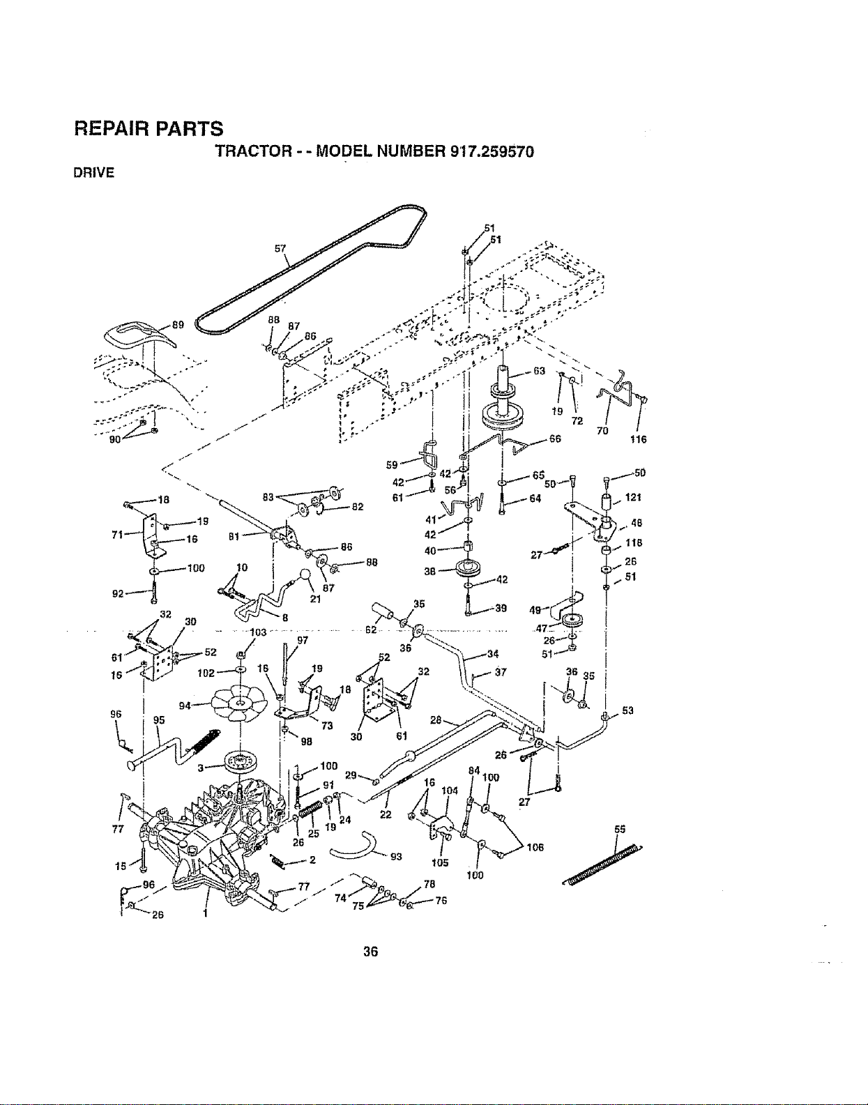
REPAIR PARTS
TRACTOR - - MODEL NUMBER 9'17.259570
DRIVE
27
36
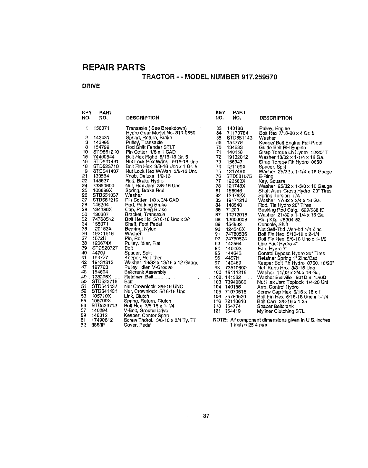
REPAIR PARTS
TRACTOR, - MODEL NUMBER 917.259570
DRIVE
KEY PART KEY PART
NO, NO, DESCRIPTION NO. NO, DESCRIPTION
l 15007! Transaxlo (See Breakdown) 63 t40186
HydroGear ModeJNo 310-0650 64 71170764
2 142431 Spring, Return, Brake 65 STD551143
3 143995 Putley, TransexJe 66 154778
8 154792 Rod Shift Fender STLT 79 134683
10 STD561210 Pin Cotter 1/8x 1 CAD 71 140156
15 74490544 Bolt Hex Flghd 5/16-10 Gr. 5 72 19132012
16 STD54143I Nut Lock He× W/ins 5/16-!8 Unc 73 156347
18 STD523710 Bolt FinHex 3/8-16Uncx 1 Gr 5 74 121199X
19 $3D541437 Nut LockHexWiWsh 3/8-16 Unc 75 12!749X
21 130564 Knob, Delu×e 1/2-13 76 STD581075
22 145627 Rod, Brake Hydro 77 123583X
24 73350600 Nut, Hex Jam 3t8-16 Uno 78 !21748X
25 106888X Spring, Brake Rod 81 156046
26 STD55t037 Washer 82 t23782X
27 STD561210 Pin Cotter 1/8x 3/4 CAD 83 19171216
28 145204 Rod, Parking Brake 64 140548
29 124236X Cap, Parking Brake 86 71209
30 130807 Bracket, Transaxle 67 19212016
32 74760512 Bolt He×Hd 5/16-18 Unc x3/4 88 12000006
34 155071 Shaft, Foot Pedal 69 154882
35 120!83X Bearing, Nylon 90 124346X
36 19211616 Washer 9t 74780536
37 1572H Pin, Roll 92 74780524
38 123674X Pulley, Idler, Flat 93 142564
39 STD523727 Bolt 94 140462
40 4470J Spacer, Split 95 144643
41 154777 Keeper, Belt Idler 96 4497H
42 19131312 Washer 13/32 x13/16 x12 Gauge 97 140469
47 127783 Pulley, Idler, V-Groove 98 73510600
49 154604 BellcrankAssembly 160 19111216
49.. 123205X .... Retainer, Belt ..............
50 STD523715 Bolt 103 73940800
51 STD54t437 Nut Crownleck 3/8-16 UNC t04 140156
52 STD541431 Nut, Crownlock 5t16-18 Uno 105 71070516
53 105710X Link, Clutch 106 74780520
55 105709X Spring, Return, Clutch 116 72110610
56 STD523712 Bolt Hex 3/8-16 x 1-1/4 1t8 154774
57 140294 V-Belt, Ground Drive 121 154419
59 140312 Keeper, Center Span
61 17490612 Screw Thdrolo 318-16 x 3/4 Ty_TT
62 8883R Cover, Pedal
Pu!iey, Engine
Bolt Hex 7/16-20 x 4 Gro 5
Washer
Keeper Belt Engine Full-Proof
Guide Belt RH Engine
Strap Torque Lh Hydro t8/20 T
Washer 13t32 x 1-1/4x 12 Ga
Strap Torque Rh Hydro 0650
Spacer, Split
Washer 25/32 x I-1/4 x 16 Gauge
E-Ring
Key, Square
Washer 25/32 x 1-5/8 x 16 Gauge
Shaft Asm. Cross Hydro 20" Tires
Spring Torsion T/A
Washer 17/32 x 3/4 x 16 Ga.
Rod, Tie Hydro 20" Tires
Bushing Rod Strtgo 6291632 |D
Washer 21/32 x 1-1/4 x 16 Ga
Ring Klip #5304_62
Console, Shift
Nut Seif-Thd Wsh-hd 1/4 Zinc
Bolt Fin Hex 5/16-16 x 2-1t'4
Bolt Fin Hex 5t6-18 Unc x I-1/2
Lfne Fuel Hydro 4"
Fan, Hydro 7"
ConlrotBypass Hydro 20" Tires
Retainer Spring I" Zinc/Cad
Keeper Bolt Rh Hydro 0750. 16/20"
Nut Keps Hex 318-16 Unc
Washer 11/'32 x 314 x 16 Ga,
102 141322 ............ Washer..Belfvilte..,501D x .1.50D..
Nut Hex JamToplock t/4-20 Unf
Arm, Control Hydro
Screw Cap Hex 5/16 x 18 x 1
Bolt Fin Hex 5/18_18 Unc x 1-It4
Bolt Cart 3/8-16 x 1 25
aCer Betlcrank
liner Clutching STL
NOTE: All component dimensions given in U S, inches
1inch= 25.4 mm
37
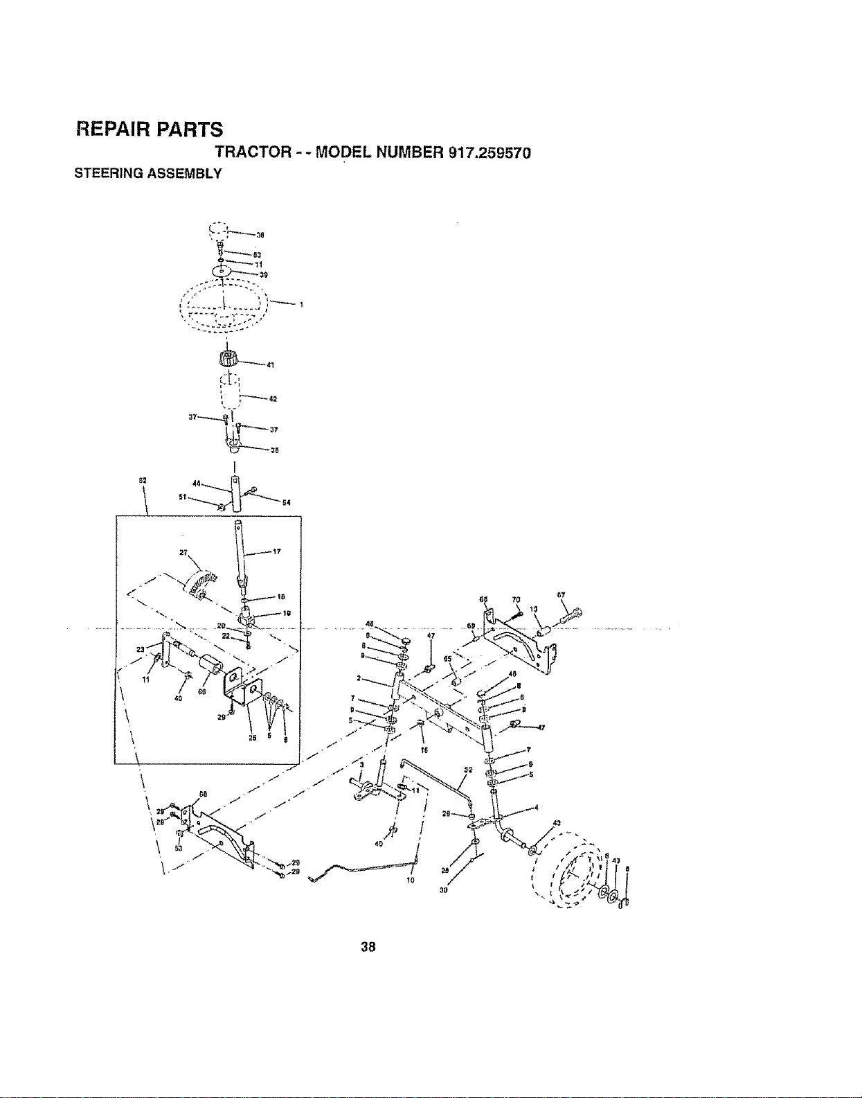
REPAIR PARTS
TRACTOR -- MODEL NUMBER 917.259570
STEERING ASSEMBLY
62
L
j , | , ,
i
I
38

REPAIR PAH 15
TRACTOR - - MODEL NUMBER 917.259570
STEERING ASSEMBLY
KEY PART
NO, NO, DESCRIPTION
1 139768
2 154427
3 156463
4 157473
5 6266H
6 121746X
7 t9272016
8 12000029
9 3366R
10 156438
11 STD551137
13 t5477g
15 739O1000
17 156546
18 57079
19 124035X
20 126684X
22 7120a410
23 127501
25 154406
26 I26647X
27 136874
28 19131416
29 17490612
30 STD561210
32 130465
36 155099
37 152927
38 139769
39 19133805
40 7810H
41 t00711L
42 145054
43 125749X
44 153720
46 121232X
47 6855M
51 73800500
54 74780520
62 156594
63 74780616
65 154780
66 154404
67 74781044
68 154429
Wheel Steering Std Black
Axle Asm Front
Spindle Asm Lh
Spindle Asm Rh
Bearing Race Thrust Harden
Washer25/32 X 1 5/8 X 16go
Washer 27/32 X ! 1/4 X 16 Ga
Ring KIfp #15304-75
Bearing Cot Strg Btk
Link Drag Extended Stamped
Washer Lock Hvy Hlcl Spr 3/8
Bearing Ax='eSTLT/GT
Locknut Flange 5t8-tl UNC
Shaft Asm Strg Private Label
Washer Thrust 515x 750x 033
Support Shaft
Washer Shim 1/4 X 5f6 × 062
Screw Hex Sckt "_/4_20x 5/6
Shaft Asm Pittman
Bracket Steering
Bushing Red Tie Btk Lt
Gear Sector
Washer 13;32 X 718X 16go
Screw Thdrol 3/8-16x3/4 Ty-It
Pin Cotler 1/8 X 3/4 Cad
Rod Tie Wire Form 19 75 Mech
Bushing S/rg 5/8 Id Dash
Screw TT #10-32x5x3/8 Range
Insert Cap Strg Wheel Std BIk
Washer 13/32 X 2-3/8 X 8 Ga
Nut Lock Center 3/8-24 UNF
Adaptor Wheel Strg
Boo( Shaft Steering
Washer 25t32 X 1 1/4 X 16 Ga
Extension Steering Non-Adjust
Cap Spindle Fr Tap Btk
Fitting Grease
Nut Lock Hex Wtlns 5/16 -18 UNC
Bolt Fin Hex 5/16 - t8 UNC X ! -I/4
Kit, Steedng Assembly
Bolt Fin Hex 3/8-16unc x t Gr-5
Spacer A×te
Bearing Arm Pi_tman
Bell Fin Hex 5!8-1 ! UNC x 2-3/4
Axle Brace
NOTE: All component dimensions given in U,S, inches
1 inch = 254 mm
39
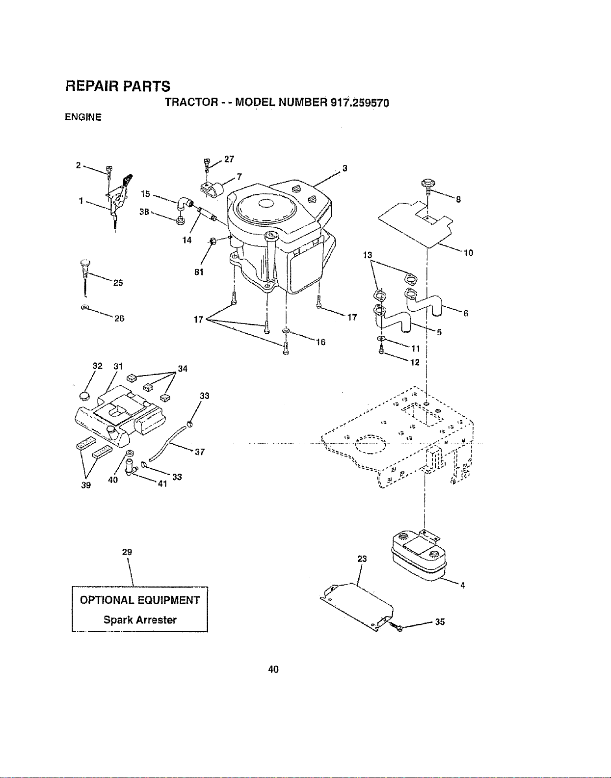
REPAIR PARTS
TRACTOR -- MODEL NUMBER 917.259570
ENGINE
J
1
32 31
4O
39
33
14
34
27
13
33
29
OPTIONAL EQUIPMENT
Spark Arrester
40
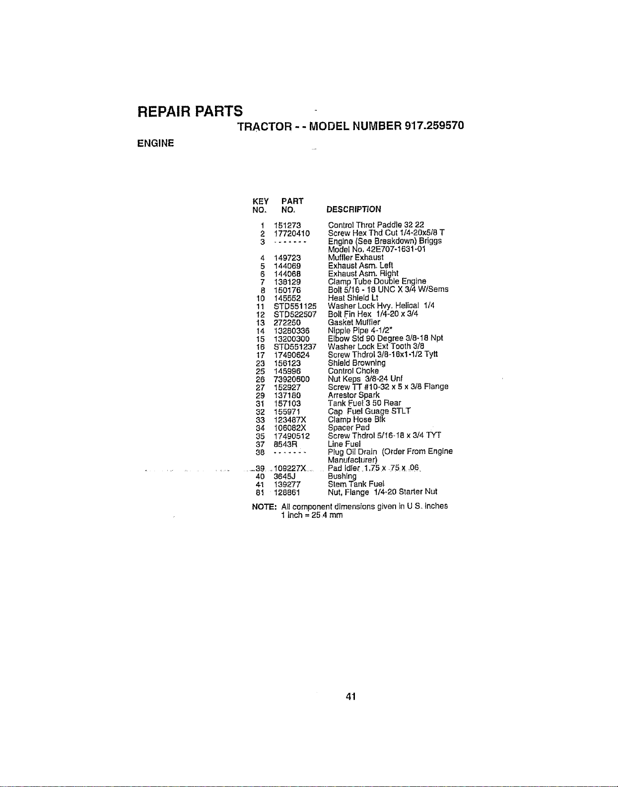
REPAIR PARTS
TRACTOR - - MODEL NUMBER 917.259570
ENGINE
KEY PART
NO, NO, DESCRIP_ON
1 151273
2 17720410
4 t49723
5 144O69
6 t44066
7 138129
8 150176
10 145552
11 STD55!125
12 STD522507
13 272250
14 13280338
15 132O0300
15 STD55!237
17 17490624
23 156123
25 145996
26 73920600
27 152927
29 _37160
31 157103
32 155971
33 123487X
34 108082X
35 17490512
37 8543R
36 ........
-39 ..109227X ......
40 3645J
41 139277
61 128861
Control Throt Paddle 32 22
Screw Hex Thd Cut t/4-20x518 T
Engine(See Breakdown) Briggs
Model No, 42E707-I631-O1
Muffler Exhaust
Exhaust Asm. Left
Exhaust Asm. Right
Ctamp Tube Doubie Engine
Bert 5/15 - 16 UNC X 3/4 W/Sems
Heat Shietd Lt
WasherLock Hvy. Helical 1/4
Bolt Fin Hex 1/4-20 x 3/4
Gasket Muffler
N}pple Pipe 4-1/2"
Elbow Std 90 Degree 3]8-18 Npt
Washer Lock Ext Tooth 3t8
Screw Thdrol 3/8-15x1-1t2 Tytt
Shield Browning
Control Choke
Nut Keps 3/8-24 Unf
Screw "IT #10-32 x 5 x 3t8 Range
Arrestor Spark
Tank Fuel3 50 Rear
Cap Fuel Goage STLT
Clamp Hose BIk
Spacer Pad
Screw Thdrol 5I_t6..I8 x 3/4 TYT
Line Fuel
Plug Oil Drain (Order From Engine
Manufacturer)
Pad idter. 1,75.X _75_ _06
Bushing
Stem Tank Fue_
Nut, Flange 1/4-20 Starter Nut
NOTE" Al! component dimensions given InU S, Inches
I inch = 25,4 mm
41
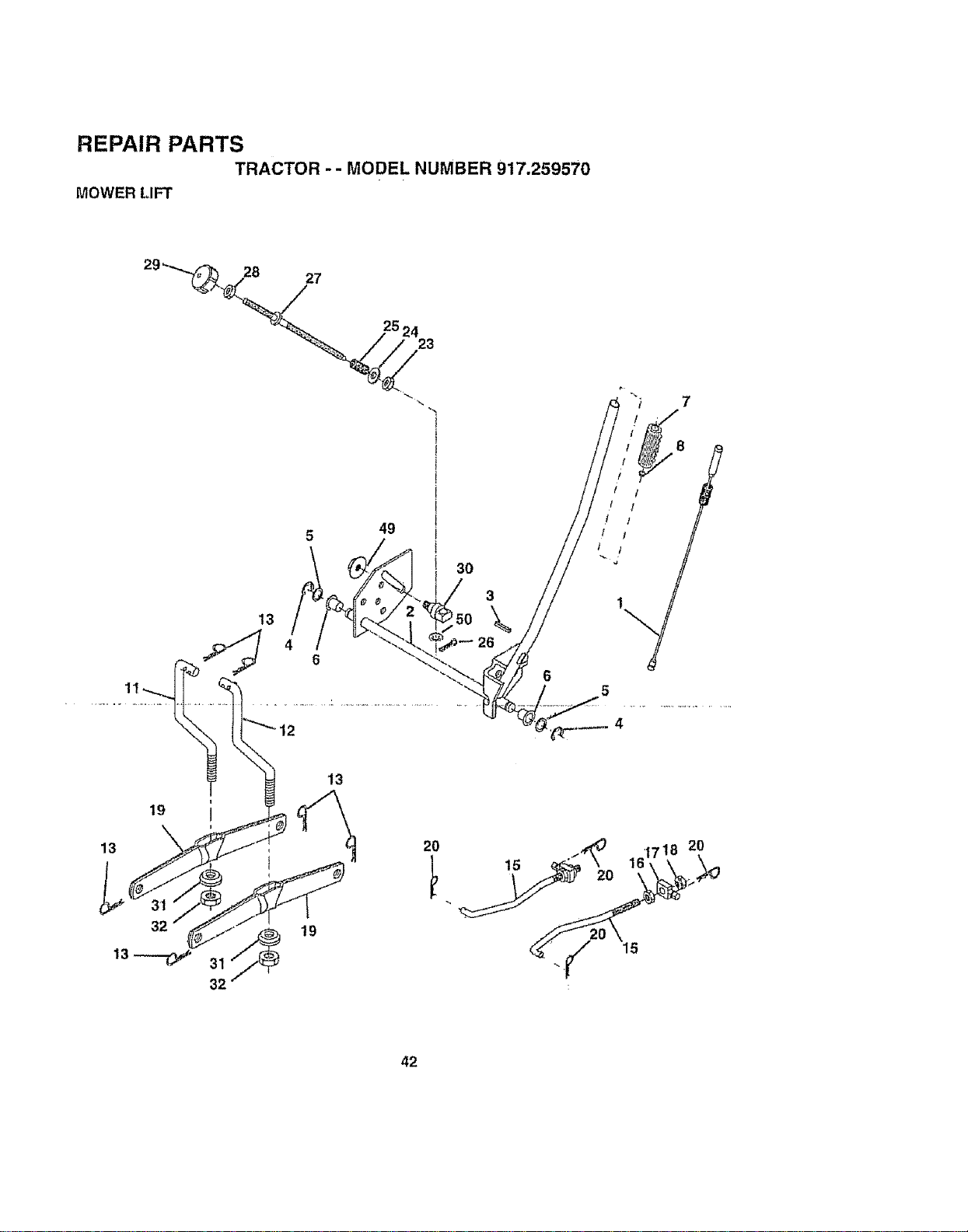
REPAIR PARTS
TRACTOR -- MODEL NUMBER 917.259570
MOWER LIFT
252423
5 49
3O
3
26
/ !
t I
t t
l 1
5
4
42

REPAIR PARTS
TRACTOR - - MODEL NUMBER 917.259570
MOWER LIFT
KEY PART
NOo NO. DESCRIPTION
1 159460
2 159471
3 105767X
4 12000002
5 19211621
6 120183X
7 125631X
8 122365X
11 139865
I2 139866
Wire Assy., Inner/Spring, w/Plunger
Shaft Asm. Lift
Pin Groove
E Ring ,/'/5133-62
Washer 21/32 x 1 x 21 Ga.
Bearing Nylon
Gdp Handle Fluted
Bufton Plunger Read
Link Uit Lh Fixed Length
Link Lift Rh Fixed Length
!3 STD624008 Retainer Spring
15 127218 Link Front
16 73350800
17 130171
18 738O08O0
19 139868
20 STD624008
23 t10807X
24 19131016
25 2875H
26 76020368
27 126971X
28 73350600
29 138057
30 150233
31 140302
32 73540600
Nut Jam Hex 1/2-t3 Une
Trunnion Blk Zinc
Nut Lock W,,Wsh 1t2-I3 Unc
Arm Suspension Rear
Retainer Spring
Nut Special
Washer 13/32 x 5/6 x 16 Ga.
Spring 2-1/8"
Pin c_tter 3t32 x 1/2
Rod Adl. Lift
Nut Hex Jam 3/8-16
Knob int'. 318-!6
Trunnion Iniin. Height
Bearing, Pivot, Lift, Special
Nut, Crownlock 3/8-24
_49_3_52_2__._uLEtange.L0.c____
50 110452X Nut Push Phos &Oil
NO?E: Allcomponentdlmenstons giventn US. inches
1inch = 25A mm
43
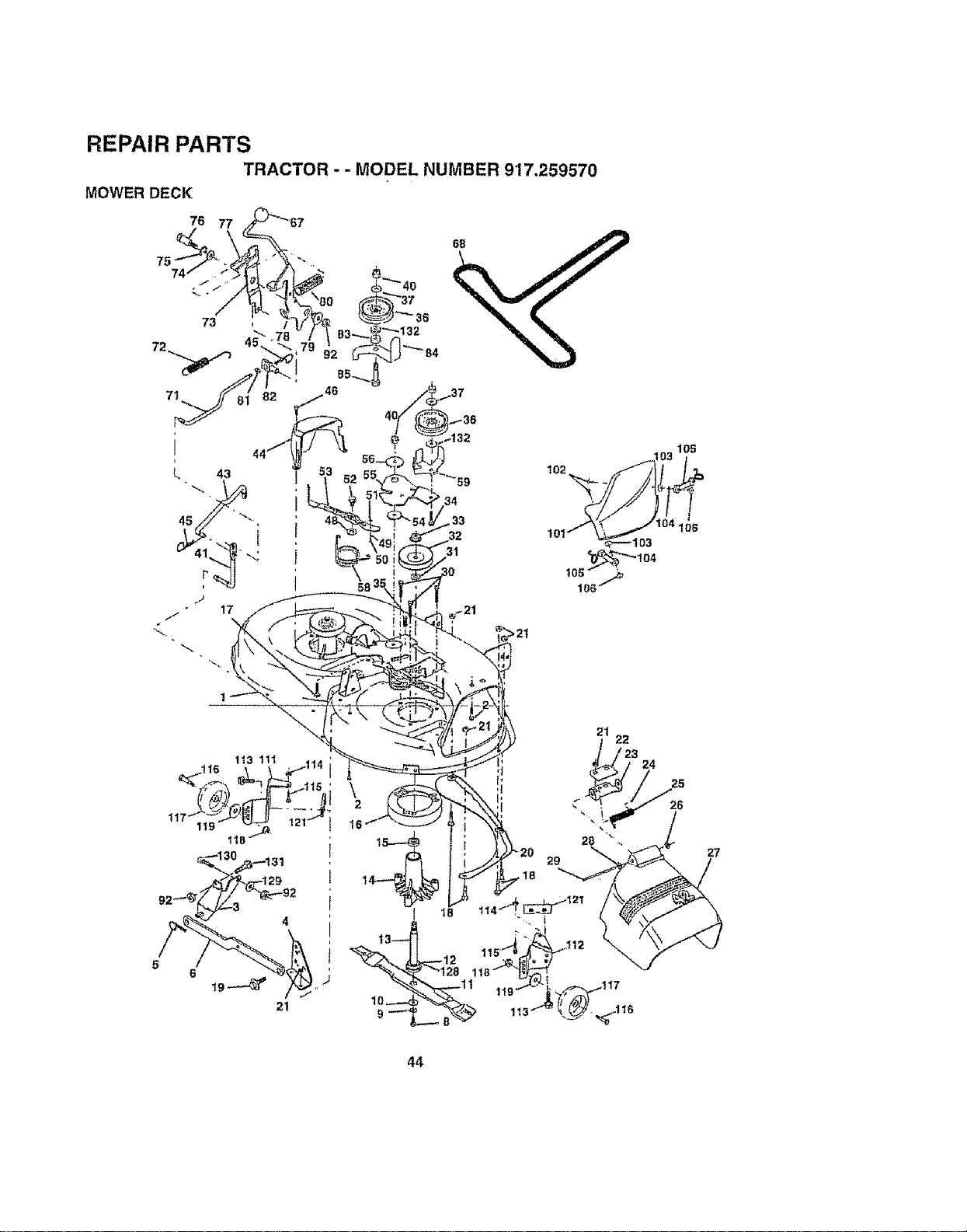
REPAIR PARTS
TRACTOR - - MODEL NUMBER 917.259570
MOWER DECK
76
37
_ 84
34
.33
31
6
21
\
21 22
_23 24
28
29
44
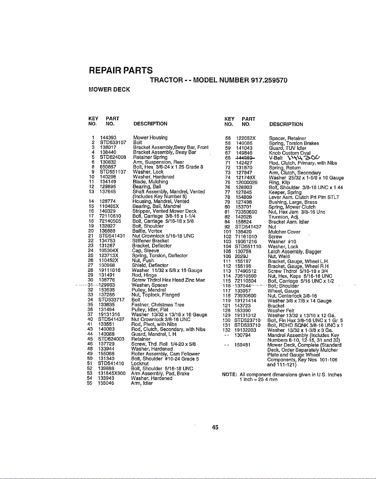
REPAIR PARTS
TRACTOR -- MODEL NUMBER 917.259570
MOWER DECK
KEY PART KEY PART
Nee NO. DESCRIPTION NO, NO. DESCRIPTION
1 144393 Mower Housing 58 122052X Spacer, Retainer
2 STD533107 Bolt 58 140066 Spring, Torsion Brakes
3 138017 Bracket Assembly,Sway Bar, Front 59 141043 Guard, TUV Idler
4 138440 Bracket Assembly, Sway Bar 67 149846 Knob Custom Oval
5 STD624008 Retainer Spring 68 .444969- V-Beit \_"N;"_',_(3_.'
6 130832 Arm, Suspension, Rear 71 142427 Rod, Clutch, Primary, with Nibs
8 850657 Boll, Hex 3/8-24x 125 Grade 8 72 131870 Spring, Return
9 STD551137 Washer, Lock 73 127847 Arm, Clutch, Secondary
10 149296 Washer, Hardened 74 121748X Washer 25/32x 1-5t8 x 16 Gauge
1! 134149 Blade, Mulching 75 12000029 Ring, Kftp
12 129895 Beadng, Bag 76 128903 BOIL,Shoulder 3t8-16 UNC x 144
13 137645 Shaft Assembly, Mandrel, Vented 77 127848 Keeper, Spring
(includes Key Number 6) 78 154809 Lever Asm. Clutch Pd Plm STLT
14 128774 Housing, Mandrel, Vented 79 127498 Bushing, Large, Brass
15 110485X Bearing, Ball, Mandrel 80 183701 Spring, Mower Clutch
16 140329 Stripper, Vented Mower Deck 81 73380600 Nut, Hex Jam 3/8-16 Unc
17 72110610 Bolt, Carriage 3/846x 1-1t4 82 142028 Trunnion, Adjo
18 72140505 Bolt, Carriage 511648 x 5/8 84 158824 BracketAsm.. ldter
19 132827 Bolt, Shoulder 92 STD541437 Nut
20 136888 Battle, Vortex 101 136420 MulcherCover
2t STD54143I NutCrownlock5/16-t8UNC 102 71161010 Screw
22 134753 Stltfener Bracket 103 19061216 Washer #10
23 131267 Bracket, Deflector 104 STD851110 Washer, Lock
24 108304X Cap, Sleeve 105 130759 Latch Assembly, Bagger
25 123713X Spring, Torsion, Deflector 106 2029J Nut, Weid
26 110452X Nut, Push 111 155197 Bracket, Gauge, Wheel L.H.
27 130968 Shield, Deflector 112 158198 Bracket, Gauge, Wheel R,H
28 19111016 Washer 11132xa/Tx16Gauge 113 17490512 ScrewThdroi 5/16-18x3/4
29 131491 Rod, Hinge 114 73510500 NuL Hex, Keps 5/16-18 UNC
30 138776 Screw Thdrot Hex Head Zinc Mwr 115 72110504 Bolt, Cardage 5/16 UNC x 1/2
.......... 31. -4 29963 Waeher_ Spacer. •116 =137644 .............. Bolt;Shou[der ....
32 153535 Pulley, Mandrel 117 133957 Wheel, Gauge
33 137266 Nut, Toploek, Flanged !18 73930600 Nut, CenteriockI/aq6
34 STD533717 Bolt 119 19121414 Washer318 x7/8 x 14 Gauge
35 133838 Fastner, ChrtstmasTree 121 143723 Brackei
36 131494 Pulley, Idler, Flat 128 153390 Washer Felt
37 19131316 Washer 13/32 x 13/16 x I6 Gauge 129 19131312 Washer t3/32 x 13116 x 12 Ga.
40 STD541437 Nut Crownlock 3/846 UNC t30 STD523710 Bolt, Fin Hex 3/8-16 UNC x 1 Gr. 5
4t 133581 Rod, Pivot, with Nibs t31 STD533710 Bolt, RDHD SQNK 3/8-16 UNC x 1
43 140083 Rod, Cfutch, Secondary, with Ntbs 132 19132203 Washer 13/32 x 1-3/8 x:3 Ga.
44 140088 Guard, Mandrel, L H -- 130794 MandreiAssembly (includes Key
48 STD624003 Retainer Numbers 8-10, 12-15, 31 and 32)
46 137729 Screw, Thd. Roll 1/4-20 x 5/8 - - 159481 Mower Deck, Complete (Standard
48 133944 Washer, Hardened Deck, Order Separately Mulcher
49 155066 Roller Assembly, Cam Follower Ptale and Gauge Wheel
50 131340 Bolt, Shoulder #10-24 Grade 5 Components, Key Nee 101-108
51 STD541410 Locknut and 111-121)
52 139888 Bolt, Shoulder 5/16-18 UNC
53 131845X900 Arm Assembly, Pad, Brake NOTE; All component dimensions given in U.S inches
54 133943 Washer, Hardened 1 inch = 25 4 mm
55 155046 Arm, ldter
45
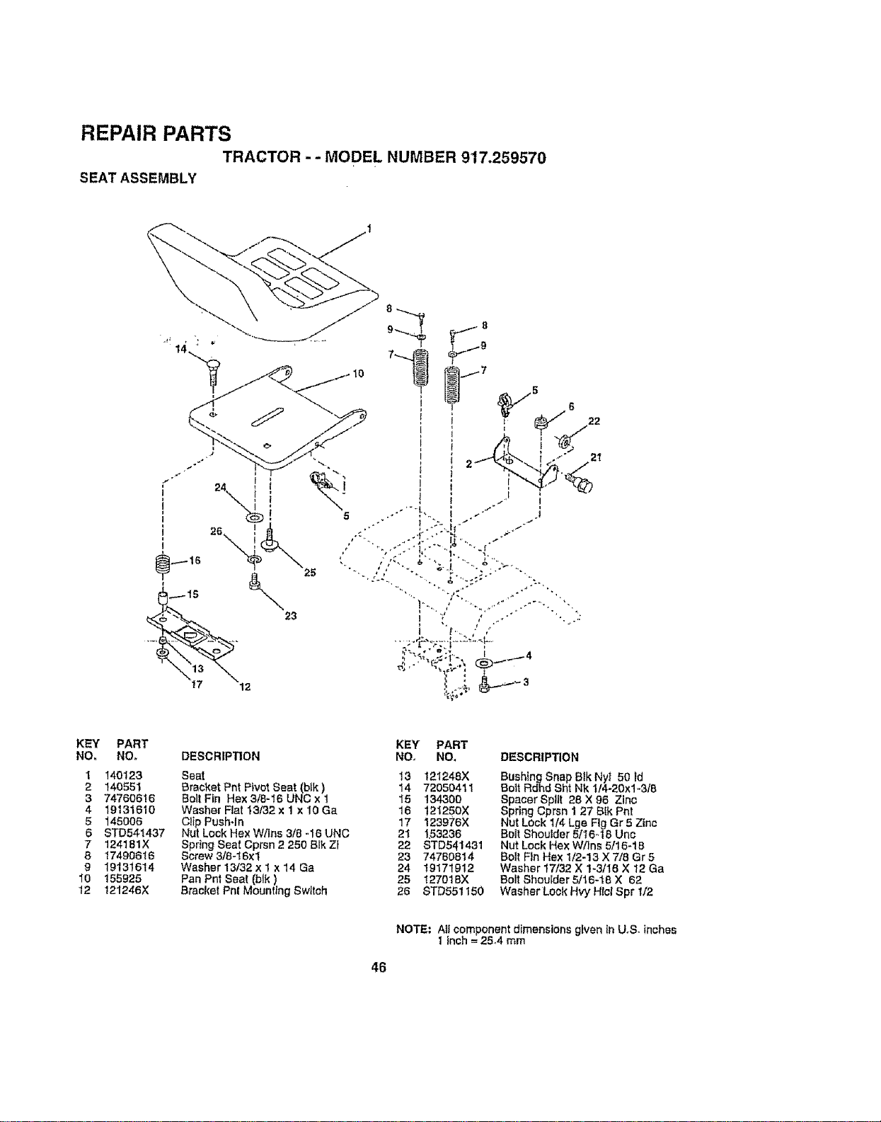
REPAIR PARTS
TRACTOR - - MODEL NUMBER 917.259570
SEAT ASSEMBLY
5
6 22
21
KEY PART
NO, NO_ DESCRIPTION
1 140123 Seat
2 140551 Bracket Pnt Pivot Seat (blk)
3 74760616 BoltFtn Hex3/8-16UNCx1
4 19131610 Washer Fiat 13/32 x 1 x 10 Ga
5 145006 Clip Push*In
6 STD541437 Nut Lock Hex W/Ins 3/8-16 UNC
7 124181X Spring Seat Cprsn 2 250 Blk Zi
8 17490516 Screw 318-16xl
9 19131614 Washer 13132 x 1 x 14 Ga
10 155925 Pan Pnt Seat (blk)
12 121246X Bracket Phi Mounting Switch
KEY PART
NO, NO, DESCRIPTION
13 121248X
14 72050411
15 134300
16 121250X
17 123976X
21 1_3236
22 STD541431
23 74760814
24 19171912
25 t27018X
Bushing Snap BIk Ny! 50 Fd
Bolt Rdhd Sht Nk 1/4-20xl-3/6
Spacer Split 28 X 96 Zinc
Spring Cprsn 1 27 Blk Phi
Nut Lock 1/4 Lge Fig Gr5 Zinc
Bolt Shoulder 5116_18 Unc
Nut Lock Hex W/Ins 5/15-18
Bolt Fin Hex 1/2-!3 X 7/8 Gr 5
Washer 17/32 X t-3/16 X 12 Ga
Bolt Shoulder 5/16-15 × 62
26 STD551150 WasherLoekHvy HlclSpr 1/2
NOTE," AIt component dimensions given tn U,S. inches
1 Inch -- 25.4 mm
46
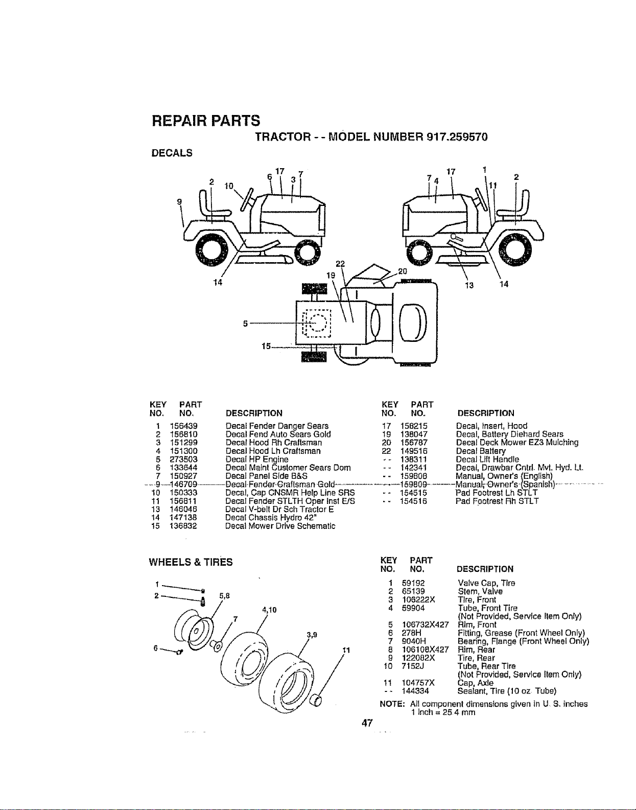
REPAIR PARTS
TRACTOR - - MODEL NUMBER 917.259570
DECALS
17
14
22
19
13 14
5
I
KEY' PART
NO. NO,
1 156439
2 156810
3 151299
4 151300
5 273503
5 133644
7 150927
--_9_--146709-----DeeaI-Fender-_raftsman Gold
10 150333 Decal, Cap CNSMR Help Une SRS
11 156811 Decal Fender STLTH Oper Inst F_JS
I3 146046 Decal V-belt Dr Sch Traclor E
14 147138 Decal Chassis Hydro42"
15 136832 Decal Mower Drive Schematic
DESCRIPTION
Decal Fender Danger Sears
Decal Fend Auto Sears Gold
Decal Hood Rh Craltsman
Decal Hood Lh Craftsman
Decal HP Engine
Decat Matnt Customer Sears Dom
Decal Panel Sfde B&S
KEY PART
NO. NO. DESCRIPTION
17 158215 Decal, insert, Hood
19 138047 Decal 8artery Diehard Sears
20 156787 Decal Deck Mower EZ3 Ma ching
22 149516 Decal Battery
- - 138311 Decal Lift Handle
- - 142341 Decal, Drawbar Cntd. Mvt. Hyd. Lt.
- - 159808 Manual, Owner's (English)
159809 ........ Manuai;Qwner's.(Spanish) ........................
*- 154515 Pad Footrest Lh STLT
- - 154516 Pad Footrest Rh STLT
4,10
11
47
KEY PART
NO. NO, DESCRIPTION
1 59192 Valve Cap, T_re
2 65139 Stem, Valve
3 !06222X Tire, Front
4 59904 Tube, Front Tire
(Not Provided, Service llem Only)
5 106732X427 Rim, Front
6 278H Fitting, Grease (Front Wheel Only)
7 9040H Bearing, Flange (Front Wheel Only)
8 106108X427 Rim, Rear
9 122082X Tire, Rear
t0 7152J Tube, Rear Tire
(Not Provided, Service Item Only)
tt 104757X Cap, Axle
- - 144334 Sealant, Tire (10 oz Tube)
NOTE: A!_component dimensions given in U S..inches
1 Inch = 25 4 mm
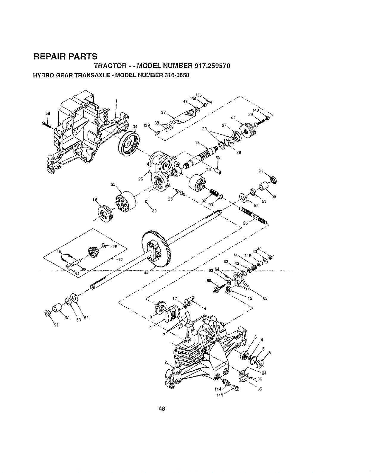
REPAIR PARTS
TRACTOR - - MODEL NUMBER 917.259570
HYDRO GEAR TRANSAXLE - MODEL NUMBER 310-0650
5B
23
26
59
2B
44
25
17
14
4
5
48
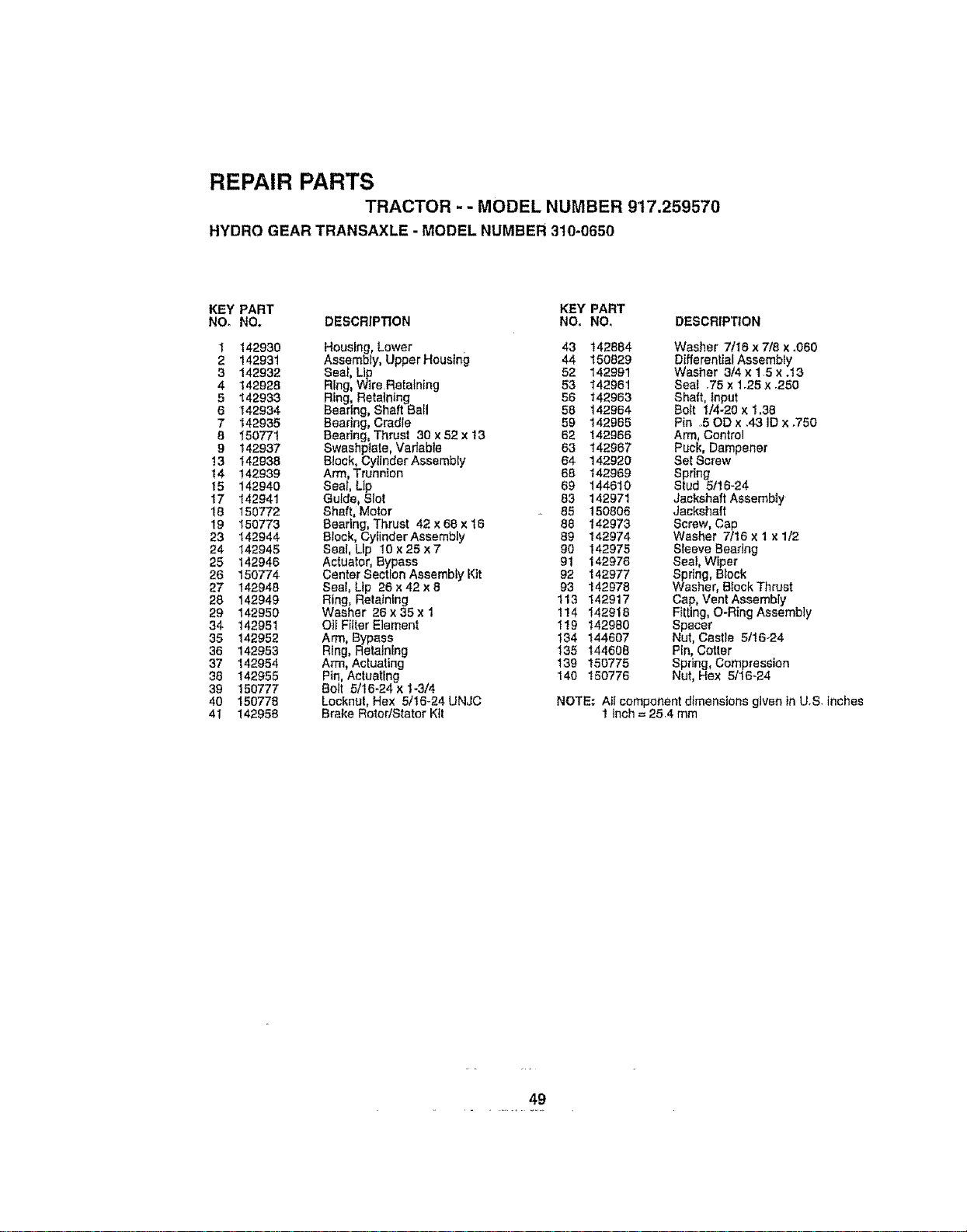
REPAIR PARTS
TRACTOR - - MODEL NUMBER 917.259570
HYDRO GEAR TRANSAXLE - MODEL NUMBER 310-0650
KEY PART KEY PART
NO. NO. DESCRIPTION NO, NO, DESCRIPTION
1 142930 Housing, Lower 43 142884
2 142931 Assembly, Upper Housing 44 150829
3 142932 Seat, Lip 52 142991
4 142928 Ring, WtreReta_ntng 53 142961
5 142933 Ring, Retaining 56 142963
6 142934 _eadng, Shaft Bail 58 142964
7 142935 Bearing, Cradle 59 142966
8 150771 Bearing, Thrust 30 x52x 13 62 142966
9 142937 Swashpfate, Vadable 63 142967
!3 142938 Btock, CytlnderAseembly 64 142920
!4 142939 Arm, Trunnion 68 142969
15 142940 Seat, Lip 69 144610
17 142941 Guide, Slot 83 142971
18 150772 Shaft, Motor 86 !50806
19 I50773 Bearing, Thrust 42 x 68 x 16 88 142973
23 142944 Block, CylinderAssembly 89 142974
24 142945 Seal, Lip 10 x 25x7 90 142975
25 142946 Actuator, Bypass 91 142976
26 150774 Center Section Assembly Kit 92 142977
27 142948 Seat, Lip 26 x 42 x8 93 142978
28 142949 Ring, Retaining 113 142917
29 142950 Washer 26x35x 1 1!4 142918
34 142951 OtI Filter Element 119 142980
35 142952 Arm, Bypass 134 144607
36 142953 Ring, Retaining 135 144608
37 142954 Arm, Actuating 139 150775
38 142955 Pin, Actuating 140 180776
39 150777 Bolt 5/16-24 x 1-3/4
40 150778 Locknul, Hex 5/16-24UNJC
4t 142958 Brake Rotor/Stator K_t
Washer 7/16 x 718 x .060
D!fferential Assembiy
washer 3/4 x 15 x .t3
Sea! .75 x 1.25 x .250
Shaft, Input
Bolt 1/4-20 x 1.38
Pin .50D x .43 tD x °750
Arm, Control
Puck, Dampener
Set Screw
Spdng
Slud 5/16-24
Jackshaft Assembly
Jackshaft
Screw, Cap
Washer 7/16x 1 x 1/2
Sleeve Bearing
Seal, Wiper
Spring, Block
Washer, Block Thrust
Cap, Vent Assembly
Fitting, O-Ring Assembly
Spacer
Nut, Castle 5t16-24
Pin, Cotter
Spring, Compression
Nut, Hex 5116-24
NOTE: AIIcomponent dimensions given in U,S inches
1inch = 25,4 mm
49
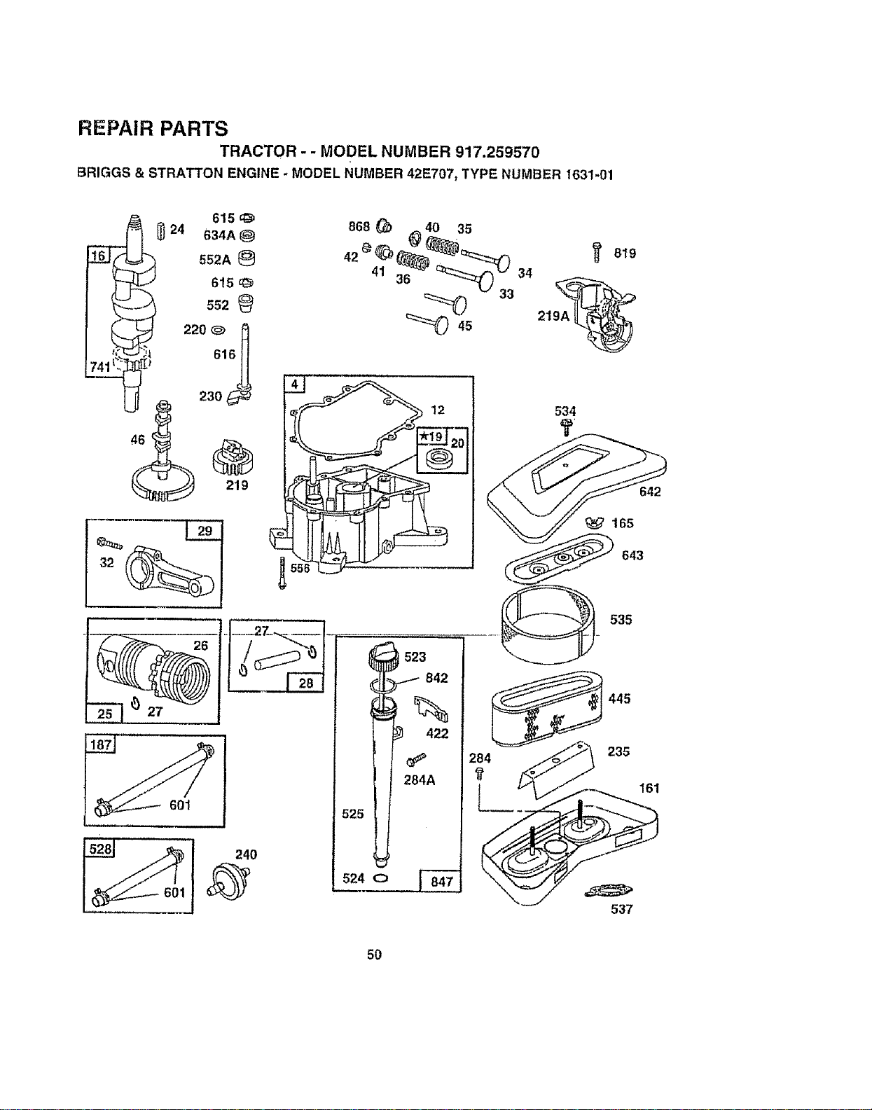
REPAIR PARTS
TRACTOR - - MODEL NUMBER 917.259570
BRIGGS & STRATTON ENGINE _MODEL NUMBER 42E707, TYPE NUMBER 1631-01
46 c
219
601
12
534
?,
642
643
523
842
%
422
284A
525
524 O _
535
445
284 235
_t
537
50
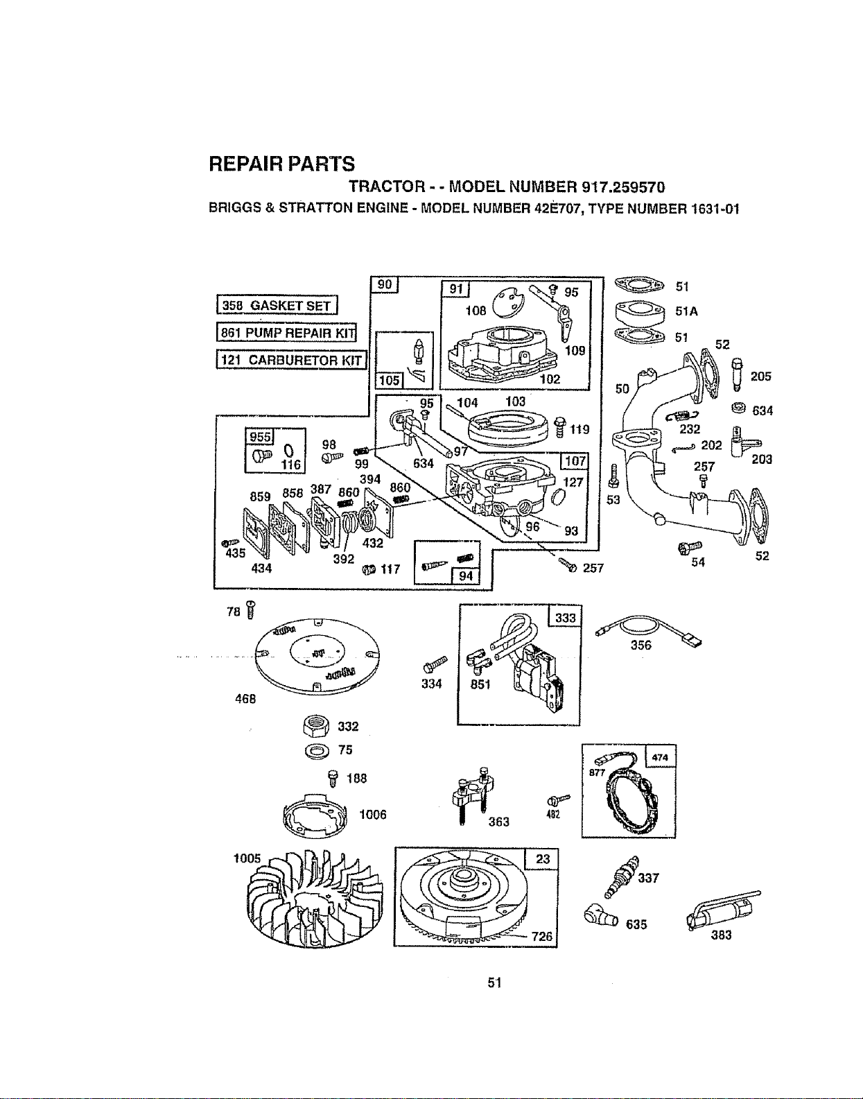
REPAIR PARTS
TRACTOR-- MODEL NUMBER 917.259570
BRIGGS & STRATTON ENGINE - MODEL NUMBER 42E707, TYPE NUMBER 1631-01
L358 GASKET SET ]
IB61 PUMP REPA!,R,,,KIT_
_"-_ _1o2 ,
"" 95 ]_104 103
,,3_"__ 3_,%2.32 m-37 f......_.2_, - -..
,,34 _,1,,_ I -_257
468
L_332
Q 75
(_ 188
1006
51
51A
5!
52
257 203
_ 52
54
37
_) 635
383
51
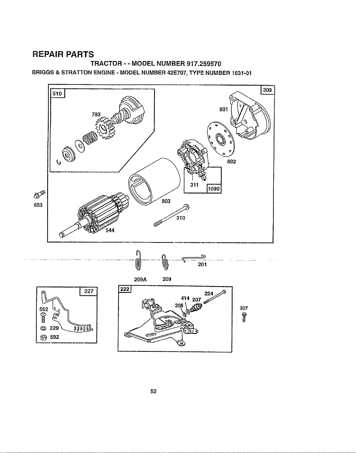
REPAIR PARTS
TRACTOR - - MODEL NUMBER 9'17.25;9570
BRIGGS & STRATTON ENGINE - MODEL NUMBER 42E707_ TYPE NUMBER I631-01
544
801
802
@ _92
209A 209
307
It
52
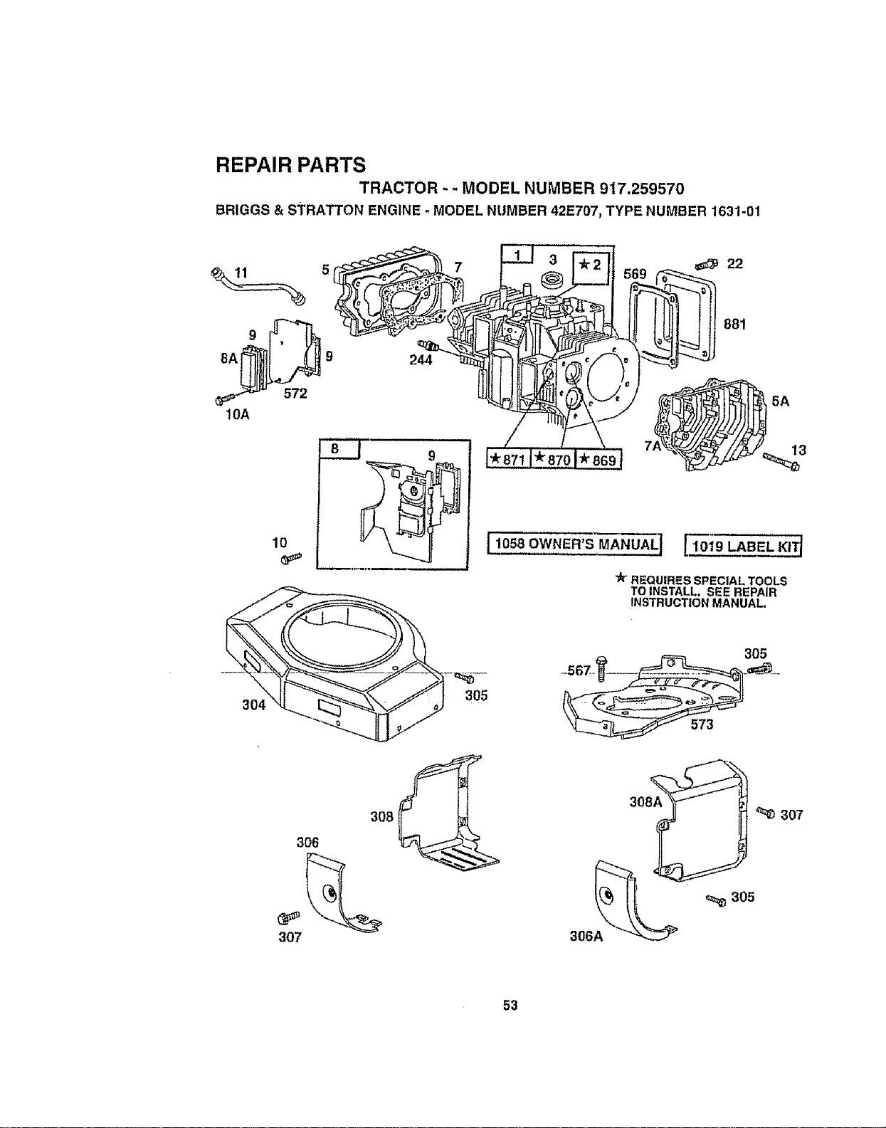
REPAIR PARTS
TRACTOR - - MODEL NUMBER 917.259570
BRIGGS & STRATTON ENGINE - MODEL NUMBER 42E707, TYPE NUMBER 1631-01
o
9
8A 9
572
!0A
244
5A
13
[1058 OWNER'S MANUAL t 110t9 LABEL KITt
'_ REQUIRES SPECIAL TOOLS
TO INSTALL, SEE REPAIR
INSTRUCTION MANUAL.
3O5
305
307
306
307
53
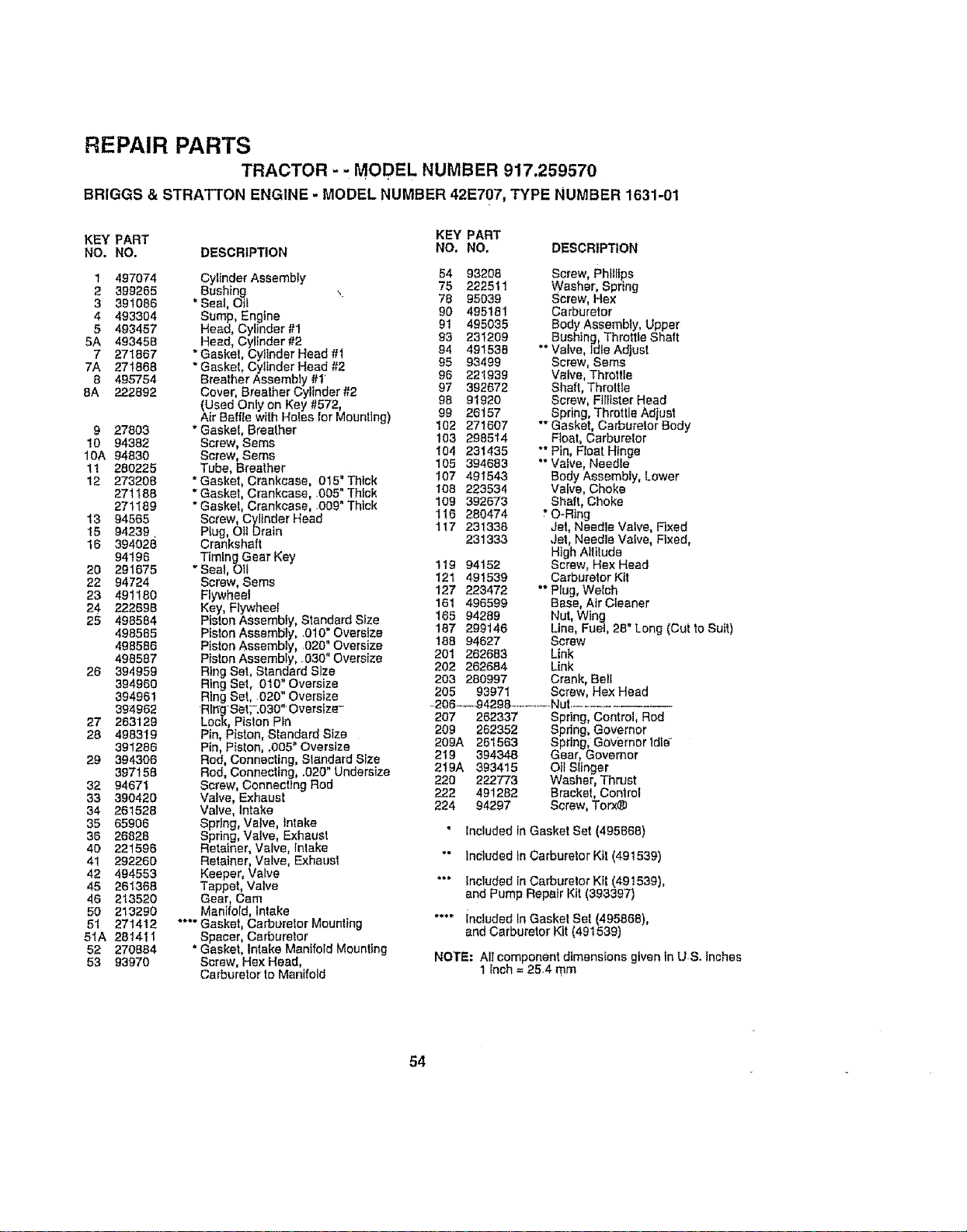
REPAIR PARTS
TRACTOR - - MODEL NUMBER 917.259570
BRIGGS & STRA'I-I'ON ENGINE - MODEL NUMBER 42E707_ TYPE NUMBER 1631-01
KEY PART KEY PART
NO. NO. DESCRiPTiON NO, NO. DESCRIPTION
1 497074
2 399265
3 391086
4 493304
5 493457
5A 493458
7 271867
7A 271868
8 495754
8A 222892
9 27803
10 94382
10A 94830
11 280225
12 273208
271165
271189
13 94565
15 94239,
16 394028
94196
20 291675
22 94724
23 491180
24 222698
25 498584
498585
498586
498587
26 394959
394950
394961
397962
27 263129
28 498319
391286
29 394306
397158
32 94671
33 390420
34 261528
35 65906
36 26828
40 221596
41 292260
42 494553
45 261368
46 213520
50 213290
51 271412
51A 281411
52 270884
53 93970
Cyttnder Assembly
Bushing
* Seat, Oi_
Bump, Engine
Head, Cylinder #1
Head, Cylinder #2
Gasket, Cyiinder Head #1
Gasket, Cyttnder Head #2
Breather Assembly #1
Cover, Breather Cylinder #2
(Used Oniy on Key #572
Air Baffle with Holes for Mounl rig)
"Gasket, Breather
Screw, Sems
ScreW, Sems
Tube, Breather
*Gasket, Crankcase, 015" Thick
"Gasket, Crankcase, .005" Thick
• Gasket, Crankcase, .009" Thick
Screw, Cylinder Head
Plug, Oil Drain
Crankshaft
Ttmlng Gear Key
"Seat, Oil
Screw, Seres
Flywheel
Key, Flywheel
Piston ASsembly, Standard Size
Piston Assembly, .010" Oversize
Piston Assembly, .020" Oversize
Piston Assembly, .030" Oversize
Ring Set, Standard Size
Ring Set, 010" Oversize
Ring Set, .020" Oversize
Ring =setT:030"'Oversize-
Lock, Piston Pin
Pin, Piston, Standard Size
Pin, Piston, .005" Oversize
Rod, Connecting, Standard S_ze
Rod, Connecting, .020" Undersize
Screw, Connecting Rod
Valve, Exhaust
Valve, Intake
Spring, Valve, Intake
Spring, Valve, Exhaust
Retainer, Valve, Intake
Retainer, Valve, Exhaust
Keeper, Valve
Tappet, Valve
Gear, Cam
Manifold, Intake
.... Gasket, Carburetor Mounting
. Spacer, Carburetor
Gasket, Intake Manifold Mounting
Screw, Hex Head,
Carburetor to Manifold
54 93208
75 222511
78 95039
90 495181
91 495035
93 231209
94 491538
95 93499
96 221939
97 392672
98 91920
99 26157
102 271607
103 2965t4
I04 231435
105 394683
I07 491543
108 223534
109 392673
116 280474
117 231338
231333
t19 94152
121 491539
127 223472
161 496599
165 94289
187 299146
188 94627
20t 262683
202 262684
203 280997
205 93971
Screw, Phillips
Washer, Spring
Screw, Hex
Carburetor
Body Assembly, Upper
Bushing Throttle Shaft
"* Valve, Idle Adjust
Screw, Seres
Valve, Throttle
Shaft, Thmttle
Screw, Ftlltster Head
Spring, Throttle Adlust
"" Gasket, Carburetor Body
Float, Carburetor
"* Pin, Float Hinge
°" Valve, Needle
Body Assembly, Lower
Valve, Choke
Shaft, Choke
" O-Ring
Jet, Needle Valve, Fixed
Jet, Needle Valve, Fixed,
High Altitude
Screw, Hex Head
Carburetor Ktt
"* Plug, Welch
Base, Air Cleaner
Nut, Wing
Line, Fuel, 28" Long (Cut to Suit)
Screw
Link
Link
Crank, Bell
Screw, Hex Head
-206-.-_94298 ...... Nut .......................
207 262337 Spring, Control, Rod
209 262352 Spdng, Governor
209A 261663 Spring; GOvernor tdl__
2t9 394348 Gear, Governor
2t9A 393415 Oil Slinger
220 222773 Washer, Thrust
222 491282 Bracket, Control
224 94297 Screw, Torx®
" included In Gasket Set (495868)
"* tncluded in Carburetor Kit (491539)
""* Included in Carbure!or Kit (491539),
and Pump Repair Kit (393397)
.... included In Gasket Bet (495866),
and Carburetor Kit (491539)
NOTE: All component dimensions given in U & Inches
1 Ench= 25_4 mm
54
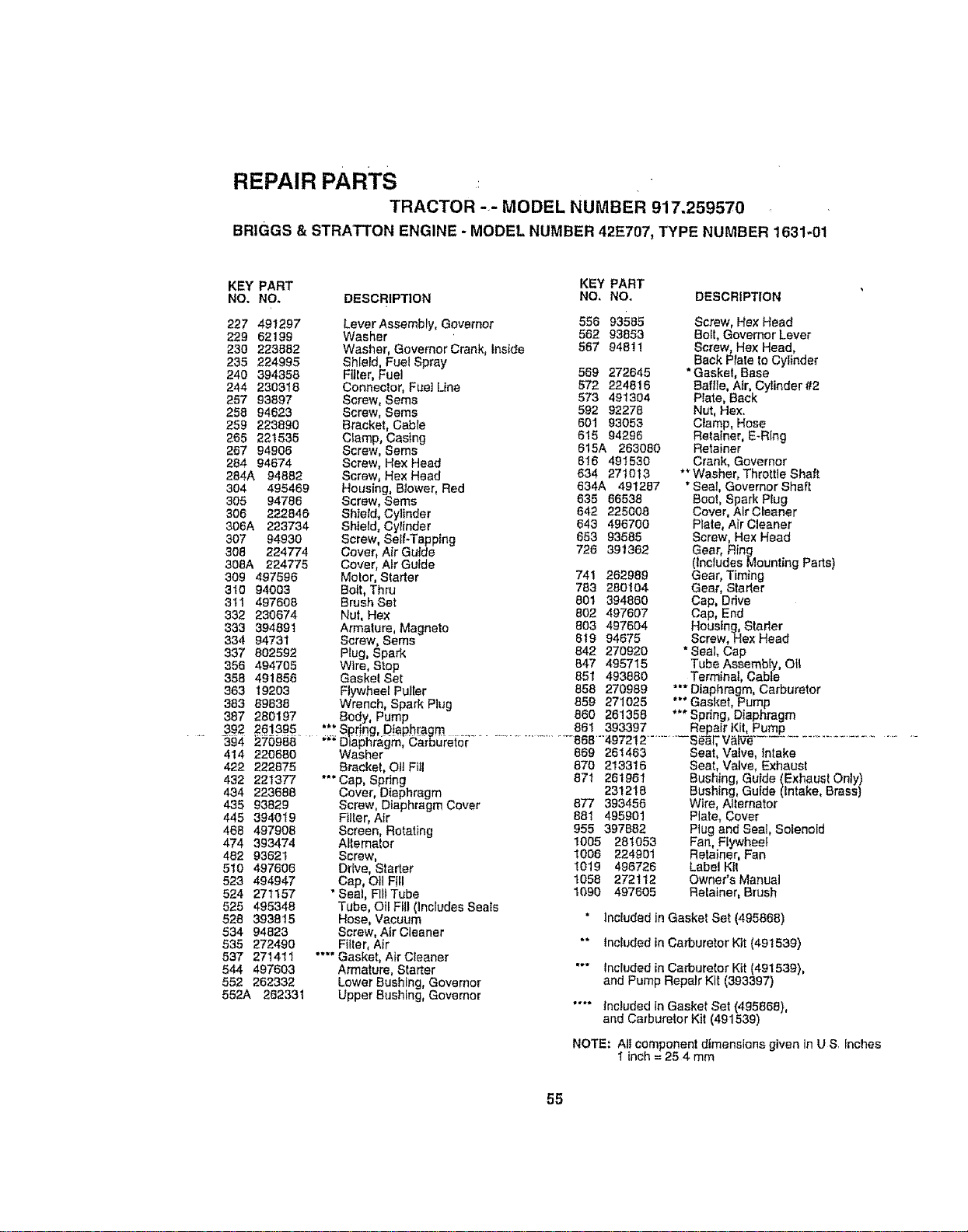
REPAIR PARTS
TRACTOR -_- MODEL NUMBER 917.259570
BR|GGS & STRATTON ENGINE - MODEL NUMBER 42E707, TYPE NUMBER 1631-01
KEY PART KEY PART
NO. NO. DESCRIPTION NO, NO. DESCRIPTION
227491297
22962199
230223882
235224995
240394358
244230318
25793897
25894623
259223890
266221535
26794906
28494674
284A 94882
304 495469
305 94786
306 222846
306A 223734
307 94930
308 224774
308A 224775
309 497596
31094003
311497608
332230674
333394891
33494731
337802692
356494705
358491856
36319203
38389838
387280197
_92 2e!P95
394 270988
414 220680
422 222875
432 221377
434 223688
435 93829
445 394019
468 497908
474 393474
482 93621
510 497606
523 494947
524 271157
525 495348
528393815
53494823
535272490
537271411
544497603
552262332
552A 262331
Love r Assembly, Governor 566 93585 Screw, Hex Head
Washer 56293853 Befl, Governer Lever
Washer, Governor Crank, Inslde 5679481! Screw, Hex Head,
Shlefd, Fuel Spray Back Plate 1oCylinder
Filler, Fuet 569272645 * Gasket, Base
Connector, Fuel Line 572224816 Baffle, Air, Cylinder #2
Screw, Sems 573491304 Plate, Back
Screw, Sems 59292278 Nut, Hex,
Bracket, Cable 60193053 Clamp, Hose
Clamp, Casing 51594296 Retainer, E-Ring
Screw, Sems 615A 263080 Retainer
Screw, Hex Head 616491530 Crank, Governor
Screw, Hex Head 634271013 ** Washer, Throttle Shaft
Housing, Blower, Red 634A 491287 "Seat, Governor Shaft
Screw, Sems 63566538 Boo!, Spark Plug
Shfeld, Cylinder 642225008 Cover, Air Cleaner
Shield, Cyttnder 643496700 Plate, Air Cleaner
Screw, Sell-Tapplng 65393585 Screw, Hex Head
Cover, Air Guide 726391362 Gear, Ring
Cover, Air Gutde (Includes Mounting Parts)
Molor, Starter 741262989 Gear, Timing
Bolt, Thru 783 280104 Gear, Starter
Brush Set 801 394860 Cap, Drive
Nut, Hex 802 497607 Cap, End
Armature, Magneto 803 497604 Housing, Starter
Screw, Seres 819 94675 Screw, Hex Head
Plug, Spark 842 270920 * Seal, Cap
Wire, Stop 847 495715 Tube Assembly, Ofl
Gaskel Set 851 493880 Terminal, Cable
Flywheel Puller 858 270989 *** Diaphragm, Carburetor
Wrench, Spark Plug 859 271025 *" Gasket, Pump
•** Spdng, Diaphragm
Body, Pump 860261358
"*" Spring, Diaphragm .......................... 86t 393397 Repair Kit, Pump
........."_" Dia6i_?aWa_hergt:n,C&rS_Ji'eio_: 869868"497212614632........... Seat,Si_l_'V_tV_Valve,.............................................Intake
Bracket, Oil Fill
*** Cap, Spring
Cover, Diaphragm
Screw, Diaphragm Cover
Filter, Air
Screen, Rotating
Altemalor
Screw,
Ddve, Starter
Cap, Oil Fill
"Sea!, Flit Tube
Tube, Oil Fill (includes Seals
Hose, Vacuum
Screw, Air Cleaner
Filter, Air
.... Gasket, Air Cleaner
Armature, Starter
Lower Bushing, Governor
Upper Bushing, Governer
870213316 Seat, VaNe, Exhaust
87t 261961 Bushing, Guide (Exhaust Only)
231218 Bushing, Guide (Intake, Brass)
877393456 Wtre, Alternator
881 495901 Plate, Cover
955 397882 Plug and Seal, Solenoid
1005 281053 Fan, Flywheef
1006 224901 Retainer, Fan
1019 496726 Label KII
1068272t 12 Owner's Manual
1090497605 Relainer, Brush
* Included in Gasket Set (495868)
"* tnc_uded in Carburetor Kit (491539)
"'" Included in Carburetor Kit (491539),
and Pump Repair Kit (393397)
.... Included In Gasket Set (495868),
and Carburetor Klt (491539)
NOTE: All component dimensions given in U Sr Inches
1 inch = 25 4 mm
55

SERVICE NOTES
56

....... _................ i_ ¸ " - ............. _ .... , _ _ _ : • .:..:... • ........
SERVICE NOTES
57

_ - _ HHHNIIH_ IIH]ll IH Ill _ I I I . . I f I I "_ I " II I "_ , _1 I I II=lh I HHIHII ' I _ I
SERVICE NOTES
58

SUGGESTED GUIDE FO_ SIGHTING SLOPES FOR SAFE OPERATION
I ""
SIGHTING
ONLY RIDE UP AND DOWN HILL,
NOT ACROSS HILL
SIGHT AND HOLD THIS LEVEL WITH
SKY LINE OR TREE.
15 ° MAX.
_i A Operate you_Tractor up and down the face of slopes (not
_1 Al, greater than _15°),never across the face. Make turns gradu-
i_ _ ally to prever_t tipping or loss of control. Exercise extreme
_| caution wher_ changing direction on slopes.
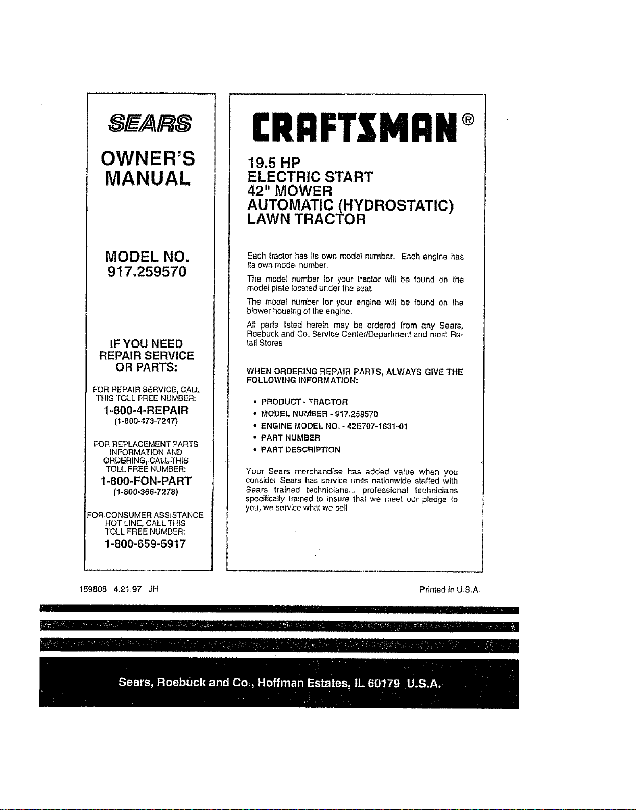
OWNER'S
MANUAL
MODEL NO.
917.259570
IF YOU NEED
REPAIR SERVICE
OR PARTS:
FOR REPAIR SERVICE, CALL
TH_S TOLL FREE NUMBER:
1-800-4-REPAIR
(1-800,473-7247)
FOR REPLACEMENT PARTS
INFORMATION AND
ORDERING r CALL-'tS-tlS
TOLL FREE NUMBER;
1-800-FON-PART
(1-800-366-7278)
:ORCONSUMER ASSISTANCE
HOT LINE, CALL THIS
TOLL FREE NUMBER:
1-800-659-5917
£RAFTSMnN®
19.5 HP
ELECTRIC START
42" MOWER
AUTOMATIC (HYDROSTATIC)
LAWN TRACTOR
Each lraclor has its own model number_ Each engine has
its own modal number
The model number for your tractor will be found on the
model plate located under the seat
The model number lor your engine wilt be found on the
b{ower housing of the engine,
AIt parts listed herein may be ordered from any Sears,
Roebuck and Coo Service CentedDepartmenl and most Rm
tait Stores
WHEN ORDERING REPAIR PARTS, ALWAYS GIVE THE
FOLLOWING INFORMATION:
' PRODUCT- TRACTOR
• MODEL NUMBER - 917o259570
• ENGINE MODEL NO, - 42E707-I631-01
• PART NUMBER
• PART DESCRIPTION
Your Sears merchandise has added va_ue when you
consider Sears has service unils nationwide staffed with
Sears trained technicians professional technicians
specifically trained to insure that we meet our pledge to
you, we service what we selt
159808 4_21 97 JH
IIIII IIIII II
it- I111.....................I illlllIiiII
IIIIIII
Printed tnU,SA
"" ' HillIIIIII_I


