
Loading ...
Loading ...
Loading ...
23
POWER SUPPLY
The electrical connections from the power supply to the
unit come pre-connected.
CAUTION: IMPROPERLY CONNECTED WIRES WILL
CAUSE DAMAGE TO THE UNIT AND MAY
RESULT IN PROPERTY DAMAGE AND/OR
PERSONAL INJURY.
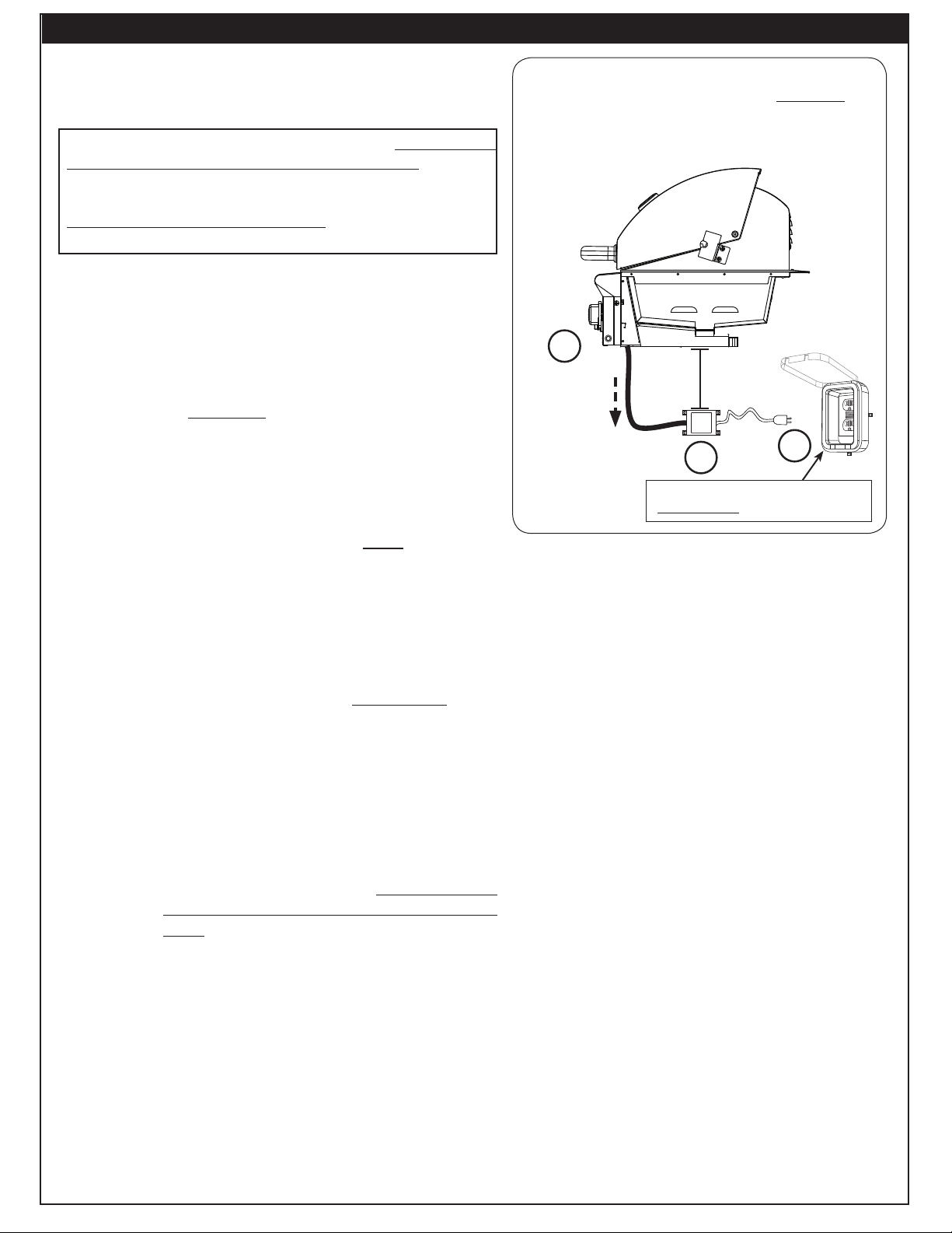
To install the power supply:
1. Route the wire harness extension below the control panel
and directly downward. This will prevent overheating.
DO NOT route the wire extension below the grill.See
Fig. 23-1, A.
Note: For enclosures with a solid area beneath the grill,
a cutout must be made near the wire extension to
allow for the above requirement. If an insulating
liner is installed, route the wire down through the
nearest hole possible.
2. Mount the power supply to the inside of the enclosure
using appropriate hardware for your enclosure. It MUST
be located at least 12 inches below the bottom of the
unit. See Fig. 23-1, B.
3. Connect the cord coming from the power supply to a
120VAC (15 AMP minimum) GFCI GROUNDED 3-wire
receptacle
(see Fig. 23-1, C). The GFCI receptacle
must be a WEATHER-PROOF IN-USE COVERED
RECEPTACLE.
WARNING: Electrical Grounding Instructions - This
appliance is equipped with a three-pronged
(grounding) plug for your protection
against shock hazard and should be
plugged directly into a properly grounded
three-prong receptacle. Do not cut or
remove the grounding prong from this
plug.
If grill accessories are to be installed and will be
powered using the same grill power supply, instead
refer to the POWER SUPPLY / WIRE HARNESS
CONNECTIONS section of the owner's manual
included with the accessory for power supply
installation.
Fig. 23-1 Electrical installation
12"
Min.
Route wires
directly
downward
(to prevent
overheating)
1. Locate power supply box
2. Route wire harness extension downward
3. Mount power supply
4. Connect cord to power source
120VAC (15 AMP minimum) GFCI
GROUNDED 3-wire receptacle
A
B
C
ELECTRICAL INSTALLATION
Loading ...
Loading ...
Loading ...