P
a
g
e
|
1
INSTALLATION
GUIDE
GUIDE
D'INSTALLATION
GUIA DE
INSTALACION
Model/Modele/Modelo
T24UC925DS
T24UC915DS
T24UC905DP
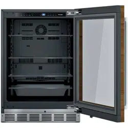
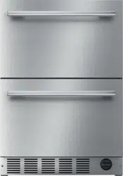
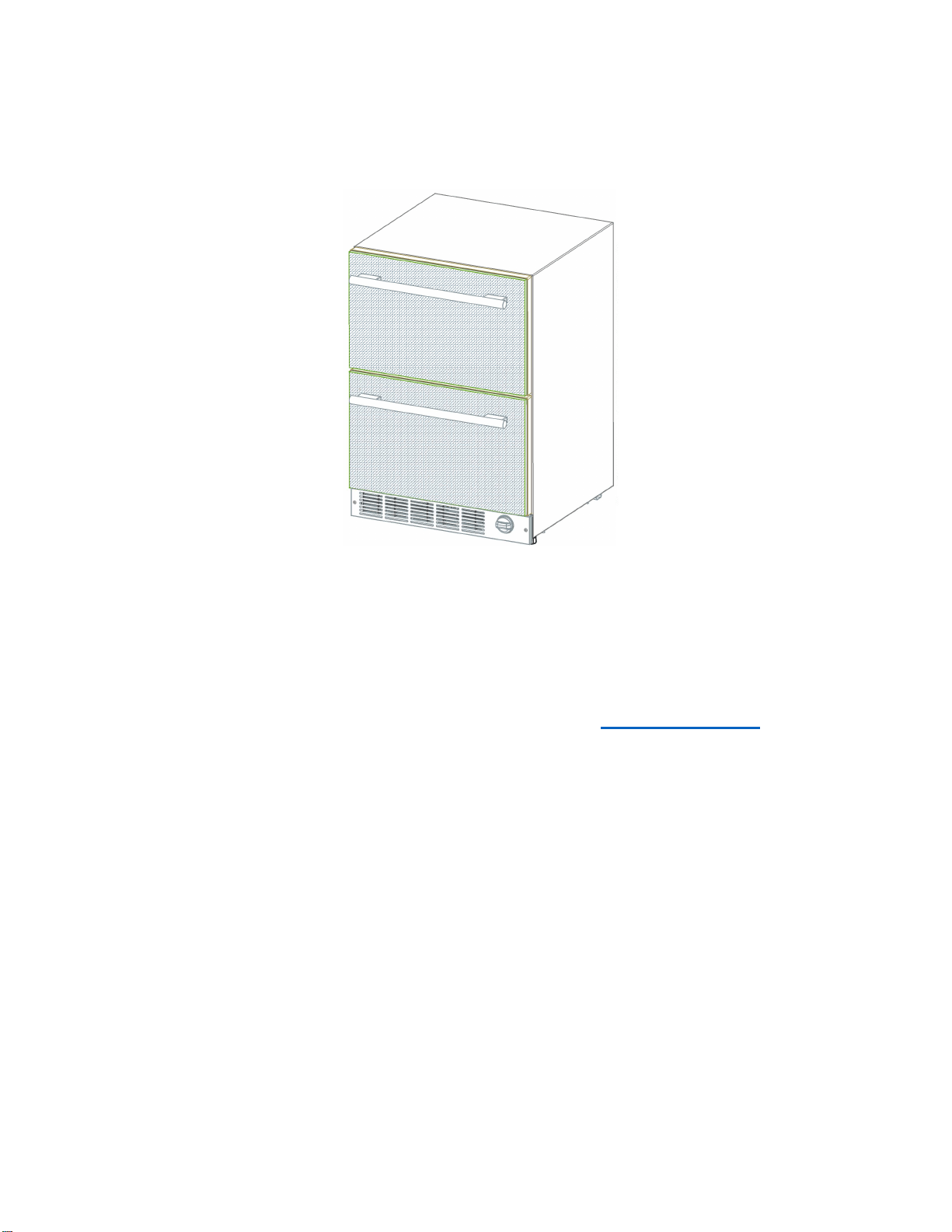
Refrigerator Freezer Drawers
Réfrigérateur Congélateur Tiroirs
Refrigerador de doble cajón con congelador

P
a
g
e
|
2
IMPORTANT:
Before you begin, read these instructions completely and
carefully.
INSTALLER:
Please leave this manual with owner for future reference.
OWNER:
Save these installation instructions for local electrical
inspector’s use and for future reference.
Table of Contents
Important Safety Instructions ….………….
3
- Inspect the Refrigerator
Tools needed for installation ……………..
4
Materials supplied …………….………….…
4
Installing the appliance …………………….
5
- Transporting
- General measures
- Installation location
- Installing side-by-side
Ventilation ……………………………………. 9
Connecting the appliance …………………
9
- Water Supply
- Electrical connections
Installing the anti-tip-bracket ……………..
12
Installing the overlay panel ………………..
16
Customer Service Information ……………
18
P
a
g
e
|
3
Important Safety Instructions
READ AND SAVE THESE INSTRUCTIONS!
These installation instructions are intended for use by qualified installers.
In addition to these instructions, the appliance shall be installed:
•
In the United States, in accordance with the
National Electric Code/State and municipal
codes and/or local codes.
•
In Canada, in accordance with the Canadian
Electric Code C22.1 –latest edition/Provincial
and Municipal codes and/or local codes.
Be sure to observe all listed warnings and cautions.
Look for the triangles with exclamation marks inside.
WARNING:
This indicates that death or serious
injury may result due to non-observance of this warning.
CAUTION:
This indicates that minor or moderately severe injury may result due to non-observance of this
warning.
NOTE:
This is used to draw the user’s attention to something in particular.
Important
•
NEW INSTALLATION – If the appliance is a new installation, most of the work must be
done before the unit is moved into place.
•
REPLACEMENT – If the appliance is replacing another appliance, the connections for
the appliance being replaced must be checked for compatibility with the new unit and
replaced as necessary.
Inspect the Refrigerator
Remove all tape, packaging and plastic covers.
After unpacking the appliance and prior to installation, thoroughly inspect the Refrigerator for possible
freight or cosmetic damage. Report any damage immediately.
NOTE: Please do not discard any bags or items that come with the original package until after the entire
installation has been completed!
P
a
g
e
|
4
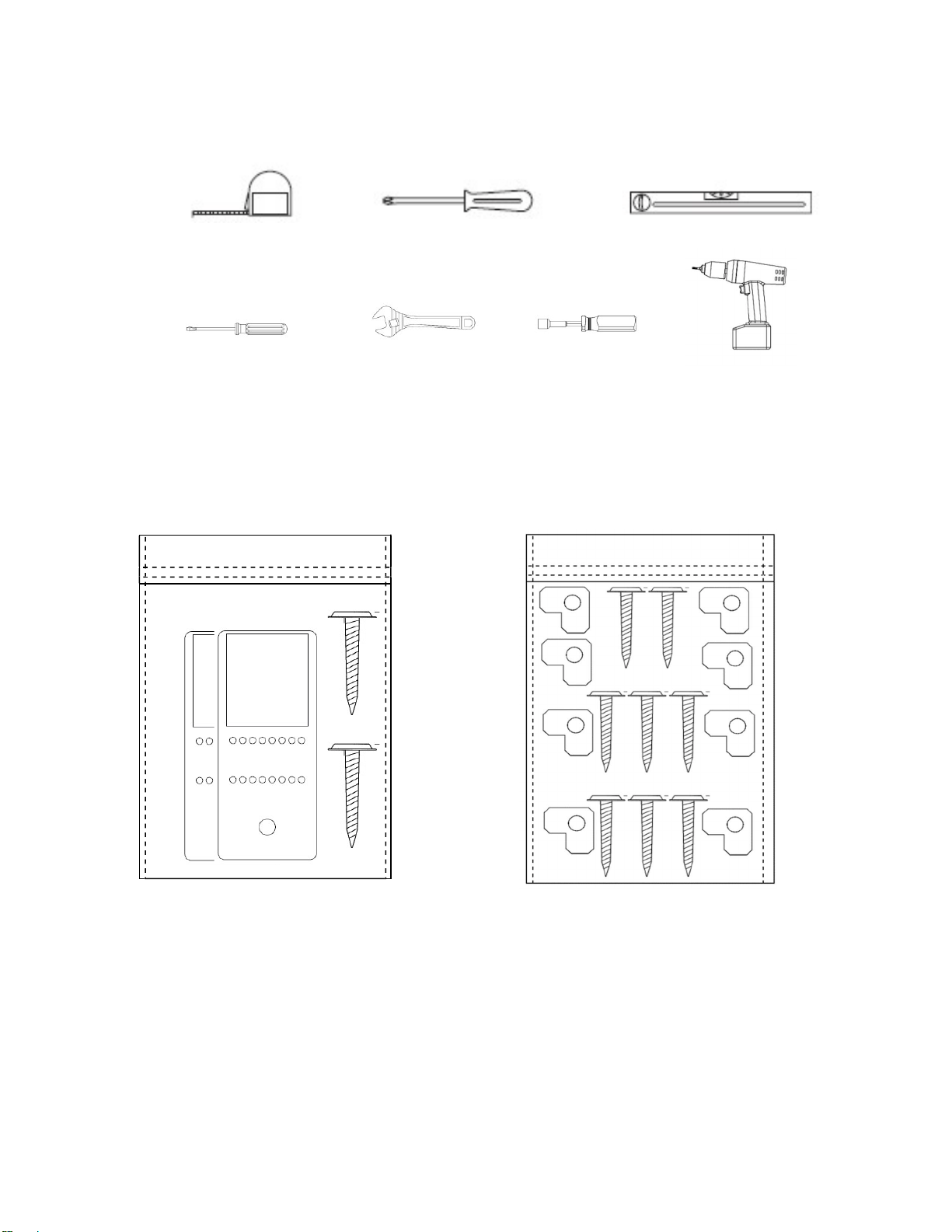
Tools needed for installation
Tape Measure Philips Screwdriver Level
Flat-blade screwdriver Adjustable wrenches ¹₄" Nut driver ¼” Drill bit & drill
These are the tools that you may need for the installation of the appliance. However, if you need to
modify the counter or cabinetry to fit the unit, you may need other tools to make counter/cabinetry
modifications before installing the appliance.
Materials supplied
Anti-tip-bracket. 2
pieces.
Screws: 2
pieces.
1 Insulating Foam
(Not
illustrated) 20
1/2”
(520mm) x 29
1/8”
(740mm) x 1/8”
(3mm)
KIT ALSO INCLUDES ONLY FOR
T24UC905DP
MODELS:
Wood Screws:8 pieces
Overlay support: 8 pieces
P
a
g
e
|
5
Installing the appliance
Most of the installation work must be done before the Refrigerator is moved into place.
Have a qualified technician install and connect the appliance according to the enclosed installation
instructions.
WARNING:
Do not install this appliance:
- Outdoors
- In an environment with dripping water
- In rooms where there is a risk of frost
Transporting
The appliance is heavy and must be handled with caution during transportation and installation.
Because of the weight and dimensions of the appliance, at least two persons are necessary to move the
appliance into position securely and avoid injuries to people or damage to the appliance.
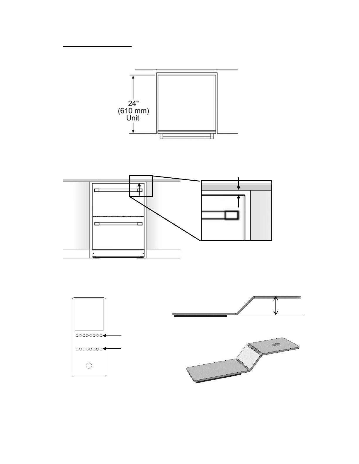
General measures
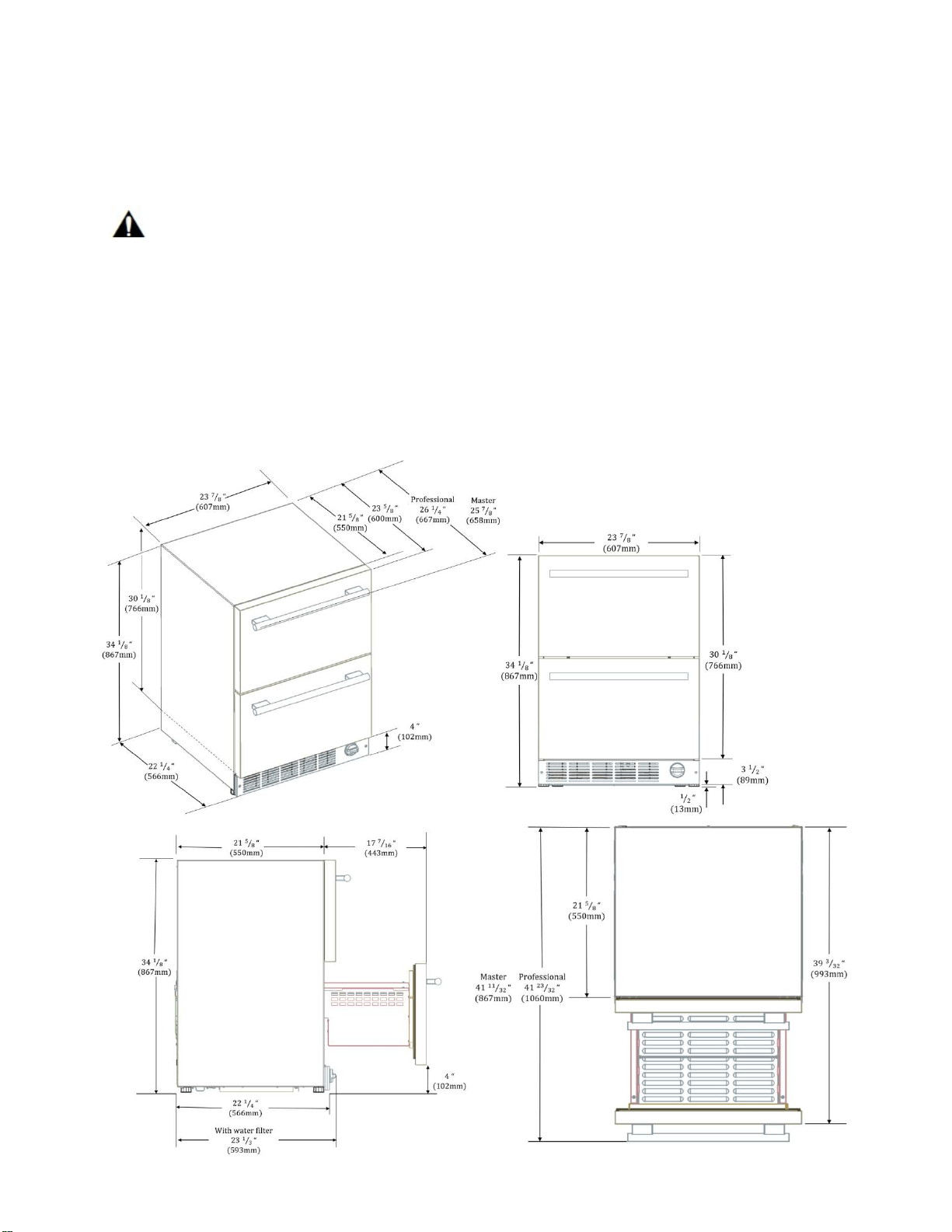
Note: With the legs fully retracted the
appliance has a minimum dimension of
34 1/8” from top to bottom. The legs
can be extended up to 1/2” (13mm).
P
a
g
e
|
6
Installation location
A dry, well ventilated room is suitable as an installation location. The installation location should not be
exposed to direct sunlight and not placed near a heat source, e.g. a cooker, radiator, etc.
If installation next to a heat source is unavoidable, use a suitable insulating plate or observe the following
minimum distance from the heat source:
▪
To electric or gas oven/range 1¼” (3 cm).
▪
To an oil or coal-fired cooker 11
13
/
16
” (30cm).
▪
To another Refrigerator or Wine Reserve 1” (2.54cm).
The floor of the installation location must not give way; if necessary, reinforce floor. The appliance must
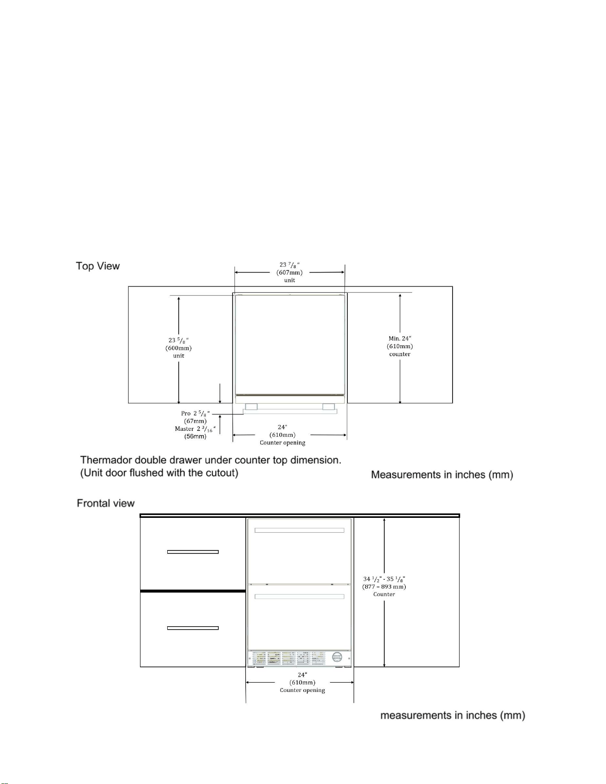
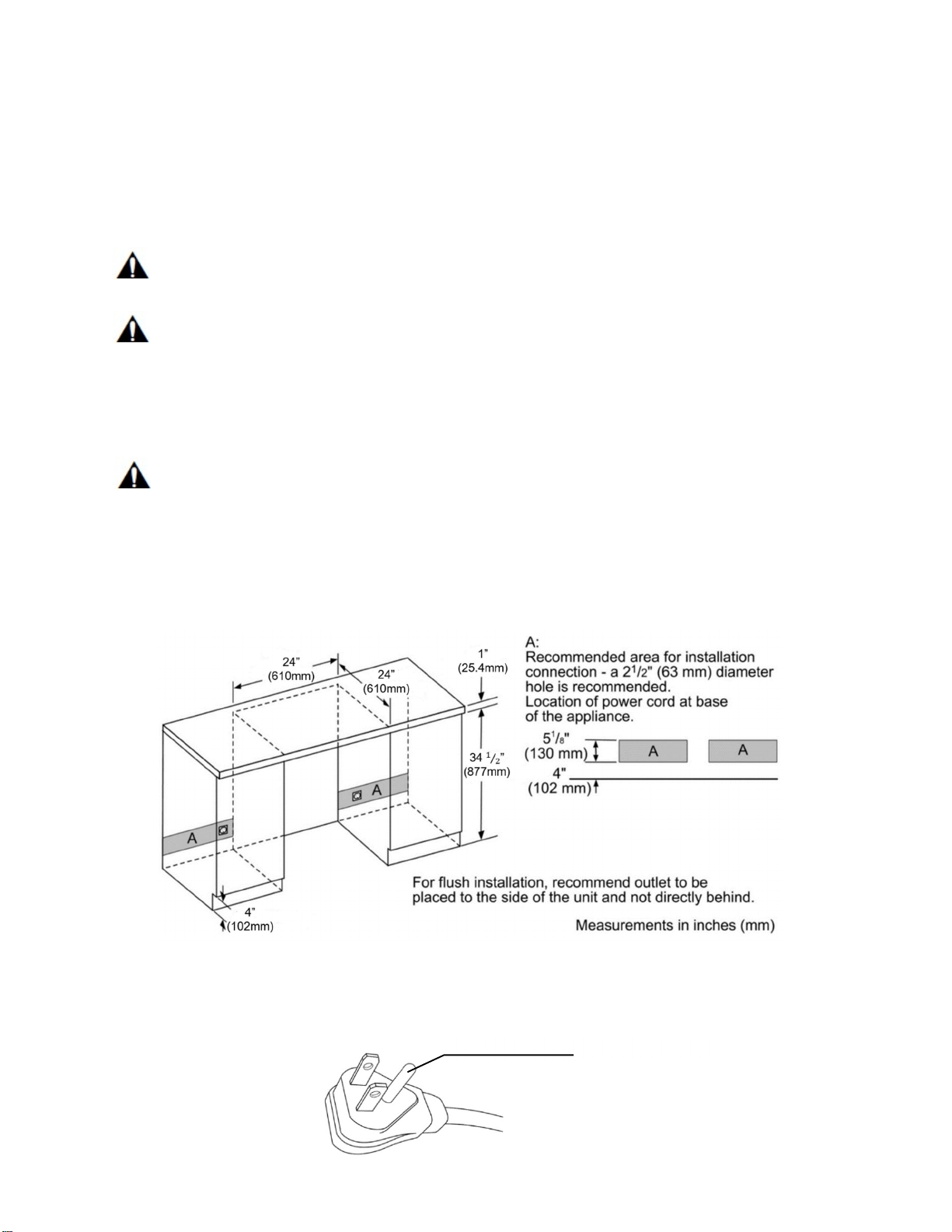
be upright and level to function correctly.
For proper operation and appearance of the unit, the cabinet opening should be square and have
dimensions as shown in the next diagrams.
P
a
g
e
|
7
Installing Side-by-Side
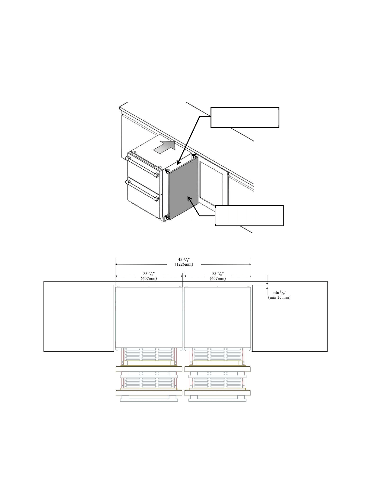
The appliance can be installed beside another Thermador appliance. Follow the next dimensions and
notes for the correct installation of the appliance in a side-by-side layout.
NOTE: Before placing the unit into the niche, adhere the Insulating Foam (included with the product) on the
side of the unit that will be placed next to the additional appliance. Be sure that the Insulating Foam is even
with the surface of the unit and that there are no bubbles or bumps on the Insulation Foam after adhering it
to the unit.
Two Double Drawer Refrigerators side-by-side.
Side of the unit next to
the other appliance.
Insulating Foam
Included with the unit.
P
a
g
e
|
8
90°
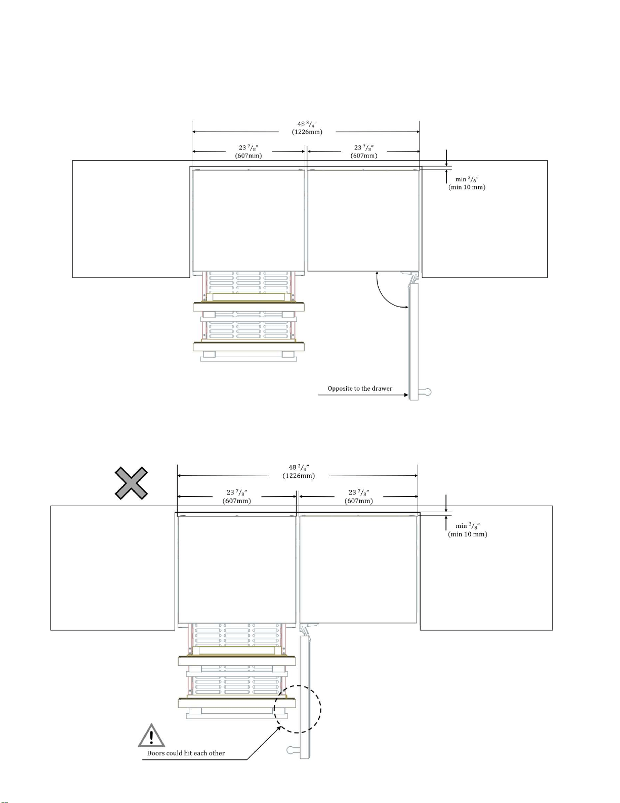
One Double Drawer and one swing door appliance: opening of the door should be opposite to the Double
Drawer to avoid interference or damage by hitting.
Do not place a swing door appliance with the opening of the door right beside the Double Drawer.
The drawers and the door may impact each other damaging the units.
13mm
½ in
(
MÍNIMUM
)
Opposite to Drawer
1224mm
48 3/16 in
607mm
23 7/8 in
607mm
23 7/8 in
!
1224mm
48 3/16 in
13mm
½ in
(
MÍNIMUM
)
Doors could hit each other
607mm
23 7/8 in
607mm
23 7/8 in
P
a
g
e
|
9
Ventilation
The Refrigerator unit is ventilated only at the Toe-Kick in the base. Never cover that area or place
anything in front of it. Otherwise the refrigeration cooling performance will be affected and the unit must
work harder increasing power consumption.
Additionally, make certain all 4 leveling legs are extended (unit height approximately 34 ¾”), so that
there is sufficient airflow underneath the appliance.
Connecting the appliance
Connect to water supply
All legs are adjustable by up to ½ inch.
IMPORTANT:
- If you turn the refrigerator on before the water line is connected, turn the ice maker OFF.
- All installations must meet local plumbing code requirements.
- Use copper tubing and check for leaks. Install copper tubing only in areas where the household
temperatures will remain above freezing.
Water Pressure
The pressure of the water supply coming out of a reverse osmosis system going to the water inlet valve of
the refrigerator needs to be between 30 and 120 psi (207 and 827 kPa).
If a reverse osmosis water filtration system is connected to your cold water supply, the water pressure to
the reverse osmosis system needs to be a minimum of 40 to 60 psi (276 to 414 kPa).
If the water pressure to the reverse osmosis system is less than 40 to 60 psi (276 to 414 kPa):
- Check to see whether the sediment filter in the reverse osmosis system is blocked. Replace the filter
if necessary.
- Allow the storage tank on the reverse osmosis system to refill after heavy usage.
- If you have questions about your water pressure, call a licensed, qualified plumber.
Connect to Water Line
1. Unplug refrigerator or disconnect power.
2. Turn OFF main water supply. Turn ON nearest faucet long enough to clear line of water.
3. Locate a ½" to 1¹₄" (1.25 cm to 3.18 cm) vertical cold water pipe near the refrigerator.
- Make sure it is a cold water
pipe.
- Horizontal pipe will work, but drill on the top side of the pipe, not the bottom. This will help
keep water away from the drill and normal sediment from collecting in the valve.
4. Determine the length of copper tubing you need. Measure from the connection on the lower left
rear of refrigerator to the water pipe. Add 7 ft (2.1 m) to allow for cleaning. Use ¹₄ (6.35 mm)
O.D. (outside diameter) copper tubing. Be sure both ends of copper tubing are cut square.
P
a
g
e
|
10
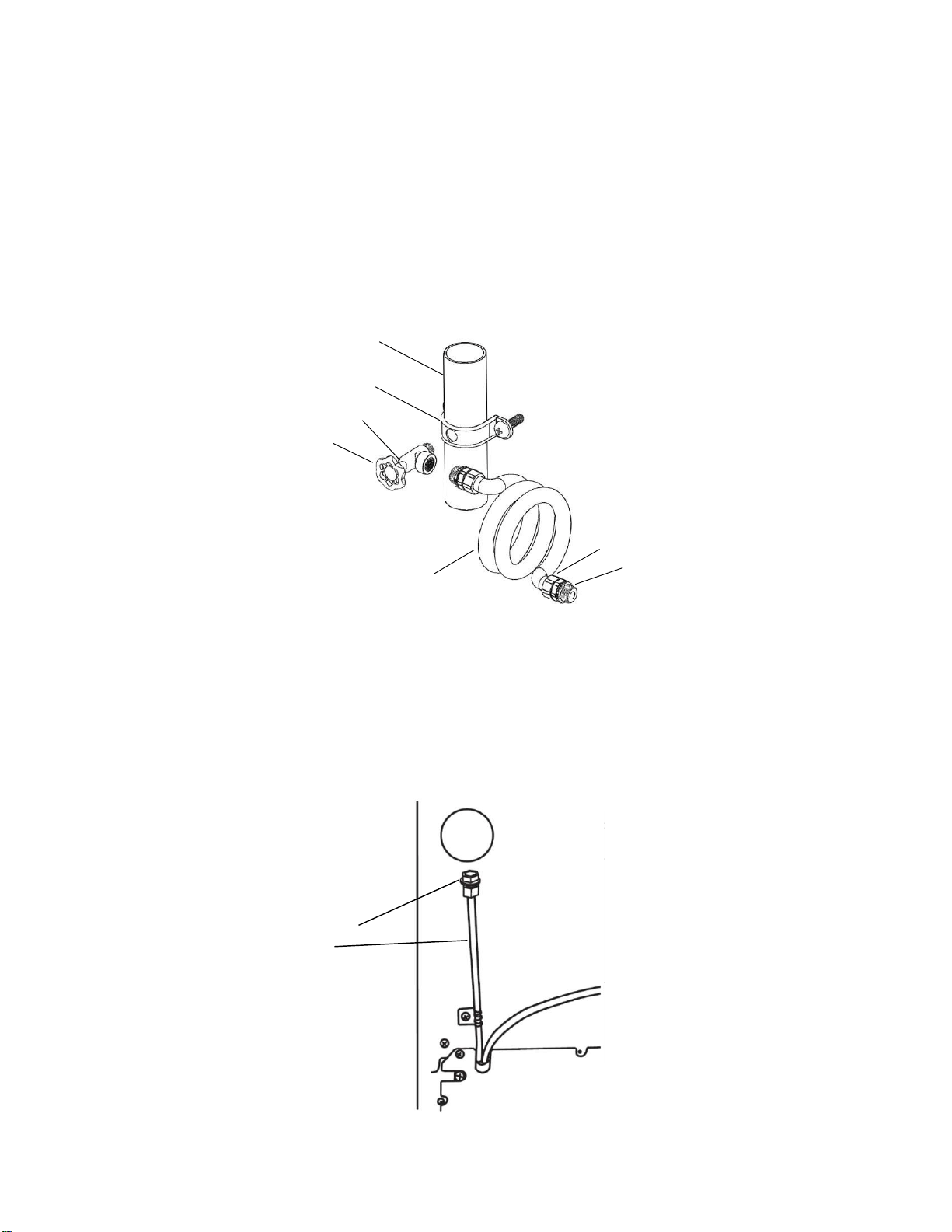
5. Using a cordless drill, drill a ¹₄" hole in the cold water pipe you have selected.
6. Fasten the shutoff valve to the cold water pipe with the pipe clamp. Be sure the outlet end is
solidly in the ¹₄" drilled hole in the water pipe and that the washer is under the pipe clamp.
Tighten the packing nut. Tighten the pipe clamp screws slowly and evenly so washer makes a
watertight seal. Do not overtighten or you may crush the copper tubing.
7. Slip the compression sleeve and compression nut on the copper tubing as shown. Insert the
end of the tubing into the outlet end squarely as far as it will go. Screw compression nut
onto outlet end with adjustable wrench. Do not overtighten.
8. Place the free end of the tubing in a container or sink, and turn ON the main water supply.
Flush the tubing until water is clear. Turn OFF the shutoff valve on the water pipe. Coil the copper
tubing.
A.
A. Cold water pipe
B. Pipe clamp
B. C. Shutoff valve
D. Copper tubing
G.
E. Compression nut
C.
F. Compression sleeve
G. Packing Nut
E.
F.
D.
Connect to Refrigerator
1. Attach the copper tube to the valve inlet using a compression nut and sleeve as shown.
Tighten the compression nut. Do not overtighten.
2. Turn shutoff valve ON.
3. Check for leaks. Tighten any connections (including connections at the valve) or nuts that leak.
4. The ice maker is equipped with a built-in water strainer. If your water conditions require a
second water strainer, install it in the ¹₄" (6.35 mm) water line at either tube connection. Obtain a
water strainer from your nearest appliance dealer.
5. Plug in refrigerator or reconnect power.
A. Compressor nut
B. Plex tubing
P
a
g
e
|
11
After installing the appliance, wait at least 1 hour to turn on the appliance. During transportation the oil
in the compressor may have flowed into the refrigeration system.
Before switching ON the appliance for the first time, clean the interior of the appliance (see chapter
“Cleaning the appliance” in the Use & Care Guide).
Electrical connection
WARNING:
These installation instructions are intended for use by qualified installers.
WARNING:
Avoid the risk of an electric shock!
Insert into a grounded receptacle.
Never remove grounding phase.
Do not use any adapters.
Do not use any extension cords.
WARNING:
It is the customer’s responsibility to ensure that the appliance installation is in compliance with all national
and local electrical codes and ordinances. Non-compliance with these instructions may result in death,
fire or an electric shock.
The receptacle must be near the appliance, 61” (1550mm) to the right of the appliance or 37” (940mm)
to the left of the appliance, and also freely accessible following installation of the appliance for future
service.
The appliance complies with protection class I. Connect the appliance to 115 V/ 60Hz alternating
current via a correctly installed receptacle with grounded terminal.
The appliance comes with a UL registered 3-wire power cord NEMA 5-15p type. The appliance
requires a 3-pole receptacle.
Never remove the grounding phase
P
a
g
e
|
12
WARNING:
Never connect the appliance to electronic energy saver plugs.
This appliance can be used with mains and sine-controlled inverters. Main controlled inverters are used
for photovoltaic systems which are connected directly to the national grid.
Sine-controlled inverters must be used for isolated applications (e.g. on ships or in mountain lodges)
which are not connected directly to the national grid.
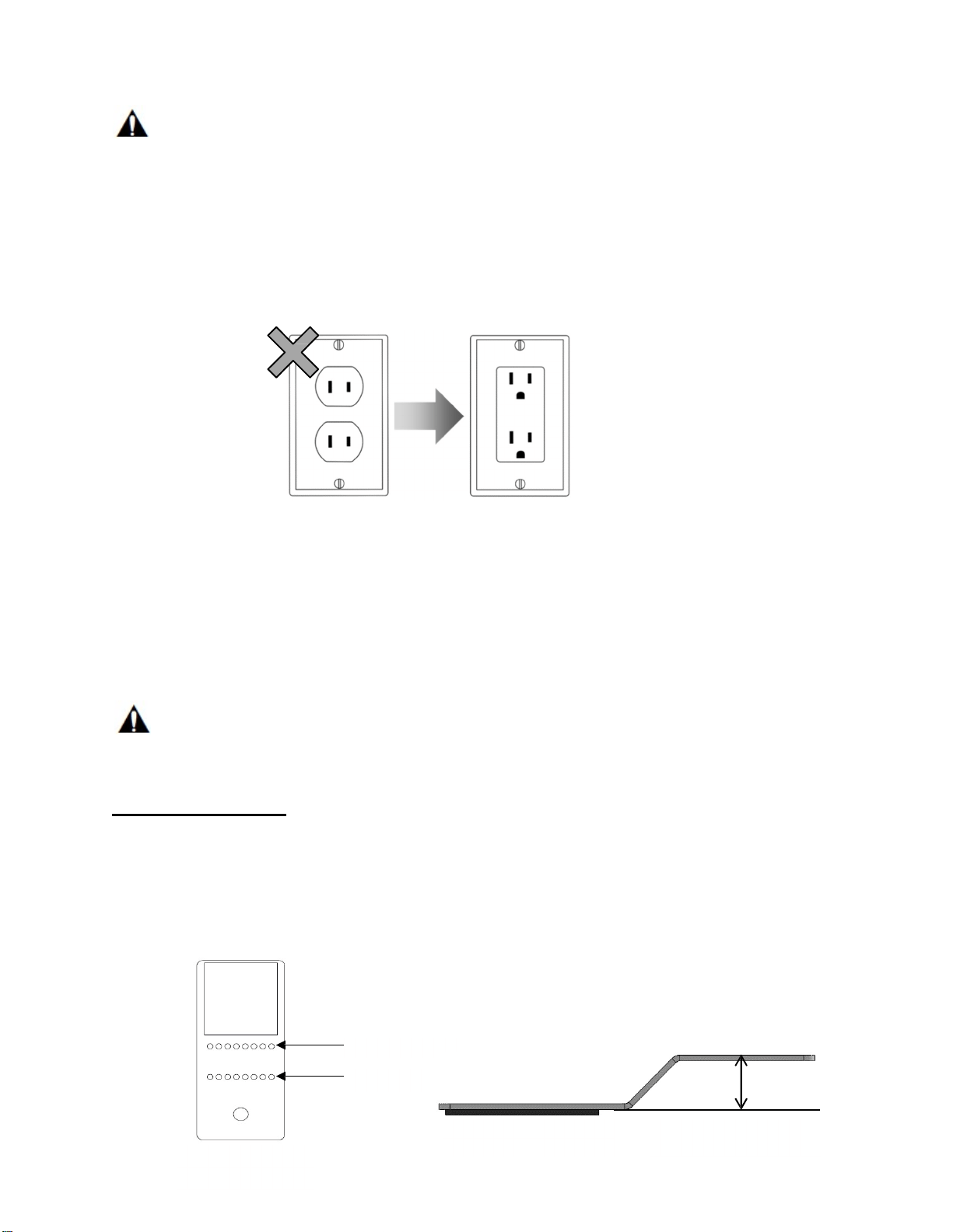
The appliance requires a 3-pole socket. The socket should be connected by a qualified electrician only.
Where there is a 2-pole standard wall socket, it is the responsibility of the customer to have this socket
replaced with a correctly grounded 3-pole wall socket. Do not use any adapter plugs.
Be sure that the location of your refrigerator has a near and accessible electric socket.
It is recommended that a separate circuit serving only your wine cellar be provided. Use an outlet that
cannot be turned off by a switch. Do not use an extension cord.
2-pole standard wall socket must be replaced with a 3-pole grounded socket. Do not use adapters.
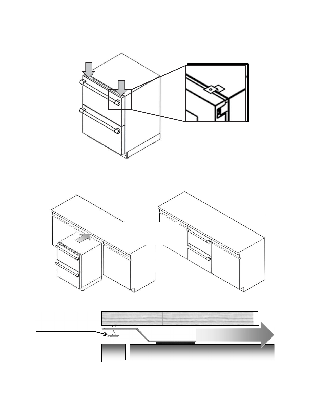
Installing the anti-tip-brackets
The appliance includes two anti-tip-brackets. If your cabinetry is not designed for the specific dimensions
of your appliance, or if you plan to use the appliance as a free-standing unit, you should use these
brackets to avoid your appliance tilting due to unbalanced overweight situations where both drawers are
opened at the same time.
WARNING:
To avoid the appliance tilting due to unbalanced overweight do not open both drawers at the same time.
Always close one drawer before pulling out another.
For free-standing use
1. Consider the distance necessary for the appliance to be flush with the front of your cabinetry. If
there is no cabinetry, put the unit close to the wall, then take the measurement of the space at the
back, between the unit and the wall.
2. Based on the measured distance between the back of the unit and the wall, bend the anti-tip
bracket (included with the unit) from the pointed lines to form a “step” with the same Distance
measured.
Bend from here
And here
Anti
-
tip
-
bracket.
2 pieces.
Adhesive foam
Distance measured
P
a
g
e
|
13
Resultant formed
“step”.
NOTE: The adhesive foam must be at the bottom
of
the step, never on the reverse
side.
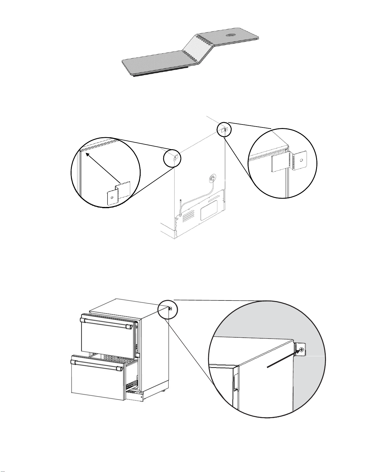
3. Peel the adhesive foam and paste the anti-tip-bracket at both sides on the back of the appliance as
shown in the illustrations.
Paste the anti-tip-bracket to the
back of the appliance.
4. With the anti-tip-brackets pasted on the back of the appliance, slide the appliance to the wall until the
anti-tip-bracket is touching the wall.
Using the screws provided, fasten the anti-tip-bracket to the wall for both sides.
NOTE: Do not fasten the unit to dry wall. Be sure to attach the unit to a solid surface.
Repeat on the
other side
Screw the bracket
to the wall.
P
a
g
e
|
14
For under counter use
1. Consider the distance necessary for the appliance to be flush with the front of your cabinetry.
2. Take the measurement from the top of the cabinet of the unit to the bottom of the counter.
The measurement X”(mm) may vary depending on the design of the counter, extension of the
legs of the product, etc.
3. Based on the Distance = X” (mm) between the appliance and the counter, bend the anti-tip-
brackets included with the appliance on the pointed lines to form a “step” 1/16” (2mm) smaller
than the Distance = X” (mm) measured.
Bend from here
Adhesive foam
Distance = X”- 1/16”
(X mm – 2mm)
And here
A
nti-tip-b
racke
t.
2 pi
ece
s.
Resultant formed “step”.
NOTE: The adhesive foam must be at the
bottom of the step, never on the reverse side.
Screw the bracket
to the wall.
Distance= X” (mm)
NOTE: the Distance = X” (mm) may vary
depending on the design of your cabinetry.
P
a
g
e
|
15
4. Peel the adhesive foam and paste the anti-tip-bracket at the front on the top of the cabinet of the
appliance, near the corners as shown in the picture:
5. Slide the appliance into the cabinet until the front of the appliance is flush with the front of the
cabinetry. Check that nothing interferes or obstructs the anti-tip-bracket while sliding under the
counter.
Using the screws provided,
screw the anti-tip bracket to
the counter to fix the unit.
C O U N T E R
A P P L I A N C E
Check that nothing obstructs
the anti-tip-bracket.
Slide the appliance into
the cabinet until the front
surfaces are flush.
P
a
g
e
|
16
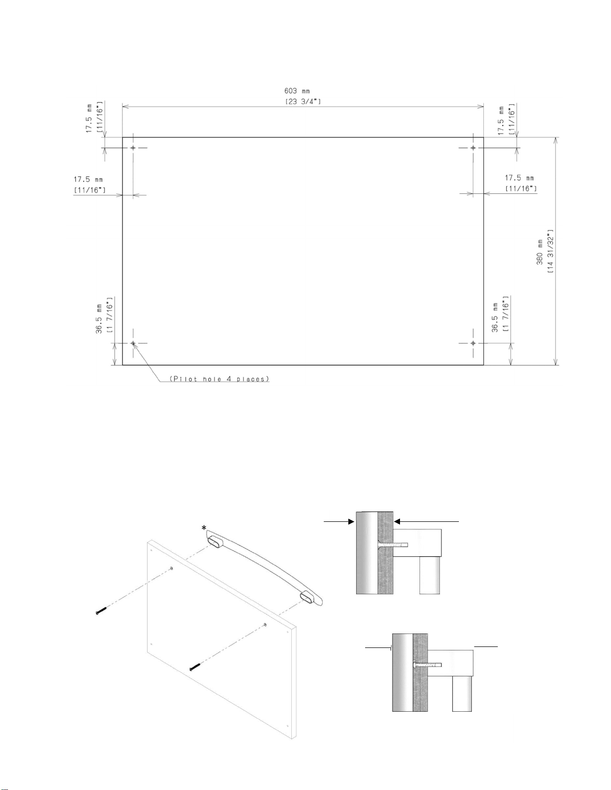
Installing the overlay panel
(For T24UC905DP models only)
If you plan to install a custom overlay panel, you will need to create the panel yourself or
consult a qualified cabinetmaker or carpenter.
A full sized template for easier marking the hole pattern is included in the manual package.
IMPORTANT:
- The thickness of both the overlay panels must be ¾” (19mm).
- Overlay panel must not weigh more than 10lbs (4.54kg) each.
- Overlay panels weighing more than recommended may cause damage to your appliance.
- It is recommended to have the help of a second person to install the panel.
- Use the recommended tools in the installation manual to facilitate the installation of the panel.
Failure to use the recommended tools or the help of a second person may result in damage to panel
and/or the appliance.
- To install the panel, use only the screws included in the “Installation Kit”.
Create the custom overlay panel using the dimensions shown.
Top Panel:
P
a
g
e
|
17
Bottom drawer:
1. Install the custom handle of your preference on the overlay panel before installing the panel on
the drawer.
- Every custom handle is different, and it is the responsibility of the customer to make the
necessary adjustments to place the handle on the overlay panel.
- The screws used to affix the custom handle to the panel must be flat and flush with the surface
of the panel (Fig A); if the screws are not flat, then consider making a recession on the overlay,
enough to hide the head of the screw below the surface of the overlay, otherwise the screws will
interfere with the correct placement of the overlay on the drawer (Fig B).
Overlay Frame with custom
Flat screw flush with su
rface
(Fig
A
)
Doo
r
Overlay Frame with
custom handle
Round head screw hidden in a recession on the overlay.
(Fig B)
P
a
g
e
|
18
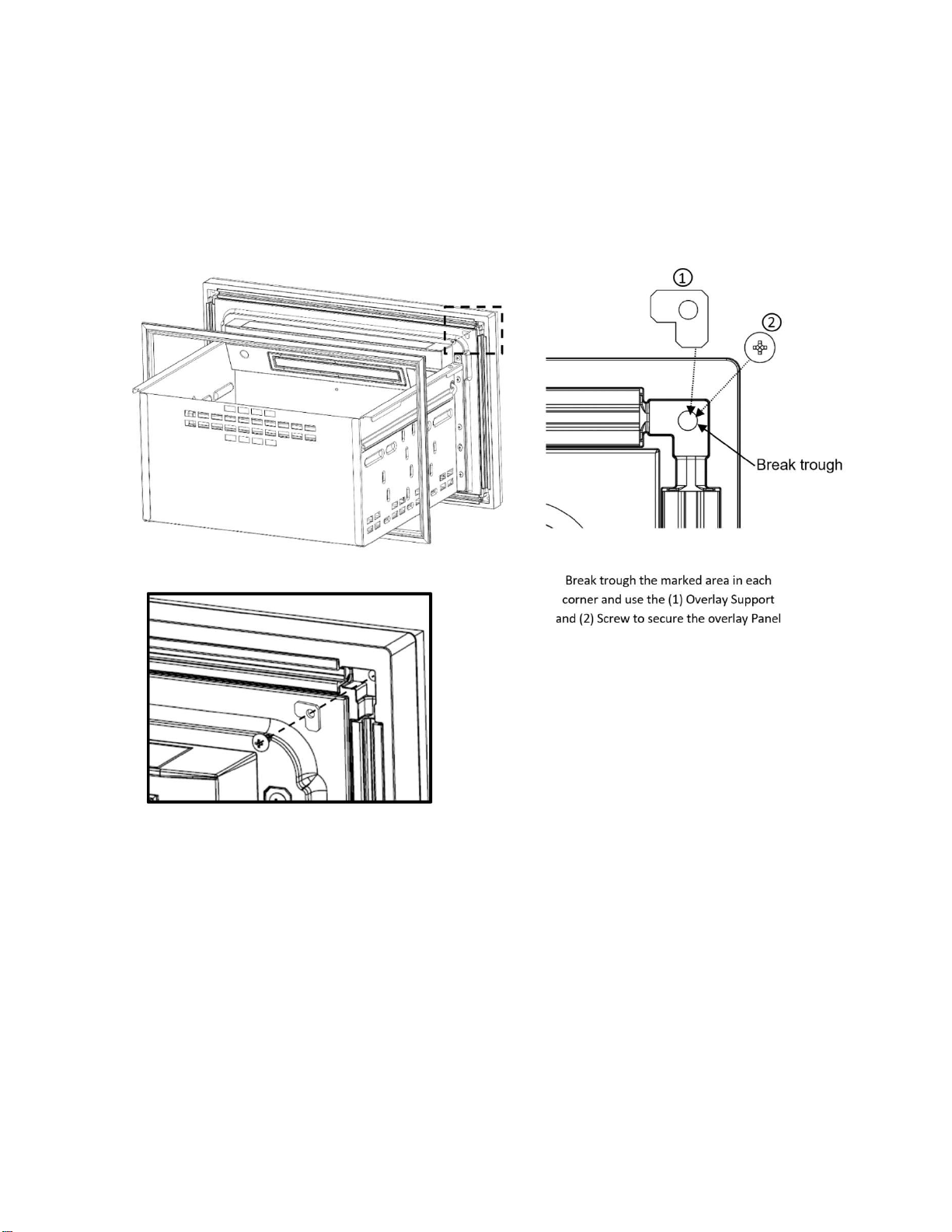
2. Remove the gasket from the top corners of the door pulling it gently. Under the gasket in each corner
there is a recess with a guide to break through to use as screw positions for the panel. It is not necessary to
remove all the gasket, only a portion enough to make the recess accessible. After the gasket is moved
break through the guides, make sure not to damage the gasket.
Using the screws and supports included in the “installation kit”, position the support in the recess and
secure the overlay panel screwing it from the inside of the drawer through the same hole left by the
removed screw until the panel is firmly attached to the drawer.
Secure the overlay using the
screws included in the
“installation kit”. There must be
one per corn
e
P
a
g
e
|
19
3. After securing the overlay to the drawer, put the gasket back in its place pressing it against its
channel on the drawer until all the gasket is even and back in place.
Repeat the same steps for the other drawer.
Now, the overlay panels are ready.
Customer Service Information
If service becomes necessary, contact your dealer or an authorized service center. Do not attempt to
repair the appliance yourself. Any work performed by unauthorized personnel may void the warranty. If
problem persists, take the following steps (in the order listed below) until the problem is corrected to your
satisfaction.
1. Contact your dealer or the Thermador Authorized Servicer in your area.
2. E-mail us from the Customer Service section of our web site, www.Thermador.com.
3. Write to us at the address below:
BSH Home Appliances Corporation
1901 Main Street, Suite 600
Irvine, CA 92614
4. Call us at: 1-800-735-4328
Please be sure to include (if writing), or have available (if calling), the following information:
• Model Number
• Serial Number
• Date of Original Purchase
• Date Problem Originated
• Explanation of Problem
Also, if writing, please be sure to include a daytime phone number. (You will find the model number and
serial number information on the label located at the right side of the bottom compartment.)

P
a
g
e
|
20
Data Rating Label
The data rating label shows the model and serial number of your appliance. It is located at the right side
of the bottom compartment.
Service Information
For handy reference, copy the information in the form below from the data rating plate located at the right
side of the bottom compartment. Keep your invoice for Warranty validation.
Model
Number
Serial
Number
Date
of
Purchase_
Dealer’s
Name_
Dealer’s
Phone
Number
Service
Center’s
Name
Service
Center’s
Phone
Number

PN: ARAH1E1050600 / 8001025790
T24UC925DS
T24UC915DS
T24UC905DP
04/2021
Printed in
Me
xico
Impreso en
Mé
xico
Imprime au
Me
xique