Loading ...
Loading ...
Loading ...
31-5000493 Rev. 0 7
Installation Instructions: Introduction and Overview
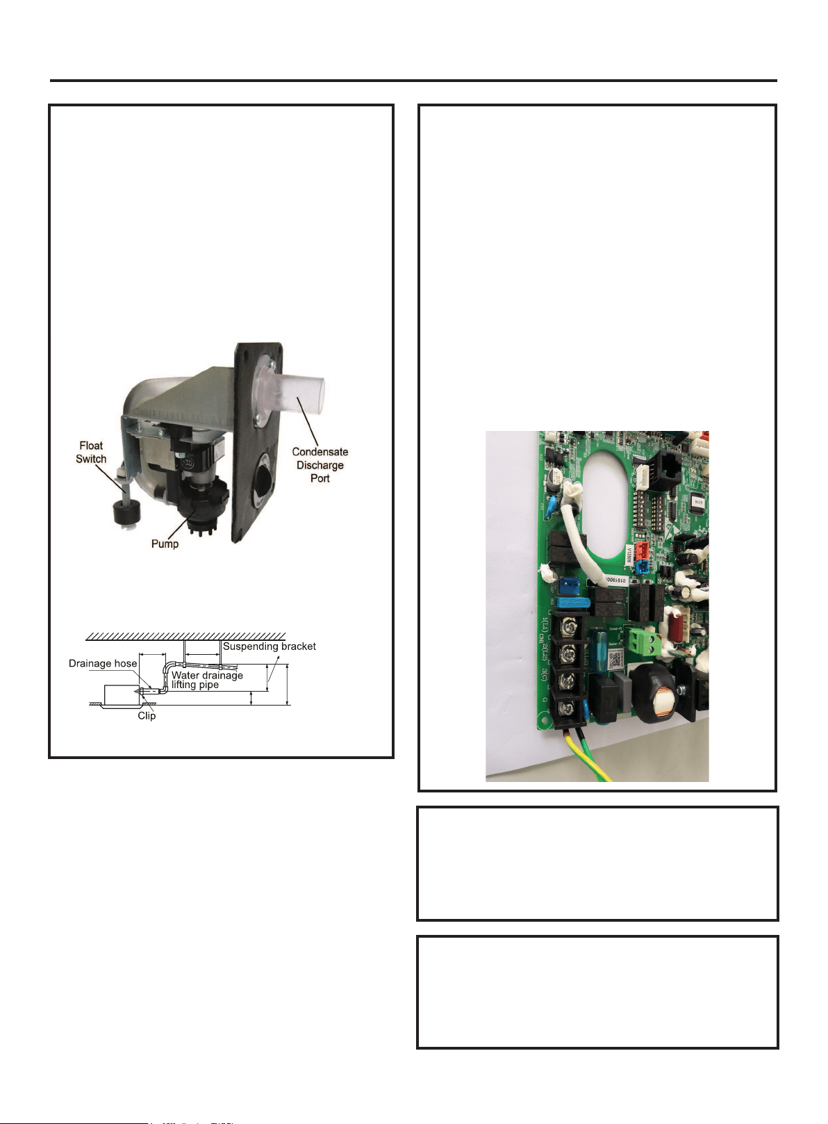
Condensate Handling
The Ducted unit has a built-in condensate pump
and water level safety switch. There are also two
optional ports for gravity drainage.
The condensate pump is rated to lift water up to 27”
from the point of discharge on the Ducted unit. (This
number may vary.)
The Ducted unit comes with a grey connection
hose and clamp. This hose is connected to the
condensate discharge hose port. The other end of
the hose is sized to accept 3/4 inch PVC piping.
Recommended condensate piping configurations are
shown here:
Electrical Power
Follow all local codes and regulations when installing
electrical wiring.
Route required electrical power to area where the
Ducted unit is to be located. Maintain at least a 10 foot
separation between TV, radio, or any communication
wiring and the power to the indoor unit.
14-gauge stranded copper wire should be used to
make the electrical connection and communication link
between indoor and outdoor units.
The wiring is connected at the indoor unit electrical
terminal blocks screws 1(L1), 2(L2), 3(C) and Ground.
There should be no splices in the wires between
the indoor and outdoor units, as these serve as
communication signal wires and electrical power
connections. Any accessory added to shut off power to
the indoor section should break the Number 2 terminal
only.
Air Delivery Clearances
Make certain to maintain proper clearances around the
Ducted unit.
Inadequate clearances can cause system operation
and temperature control problems.
Service and Maintenance Clearances
Make sure there are adequate clearances for future
maintenance and service. Allow enough room to
access the condensate pump assembly and the
electrical control box.
12 in. below
3-5 ft.
11 in. under
8.6 in.
8.6 in.
19.6 in. below
Loading ...
Loading ...
Loading ...