Loading ...
Loading ...
Loading ...
12
31-5000493 Rev. 0
Installation Instructions
Auxiliary Heat Installation Instructions
1. Field Supplied Materials Needed
• Correct size Duct heater meeting the specifications
outline herein (Warren Technology Quicksilver Series
or equivalent).
• Electrical Disconnect switch properly sized per the
power requirements
• Properly sized wire and circuit breaker
2. Heater: The duct heater should have the following
components
• 230 X 24v transformer
• Air proving switch
• Line voltage fusible links as specified by ANSI
• Low voltage limit switch as specified by ANSI
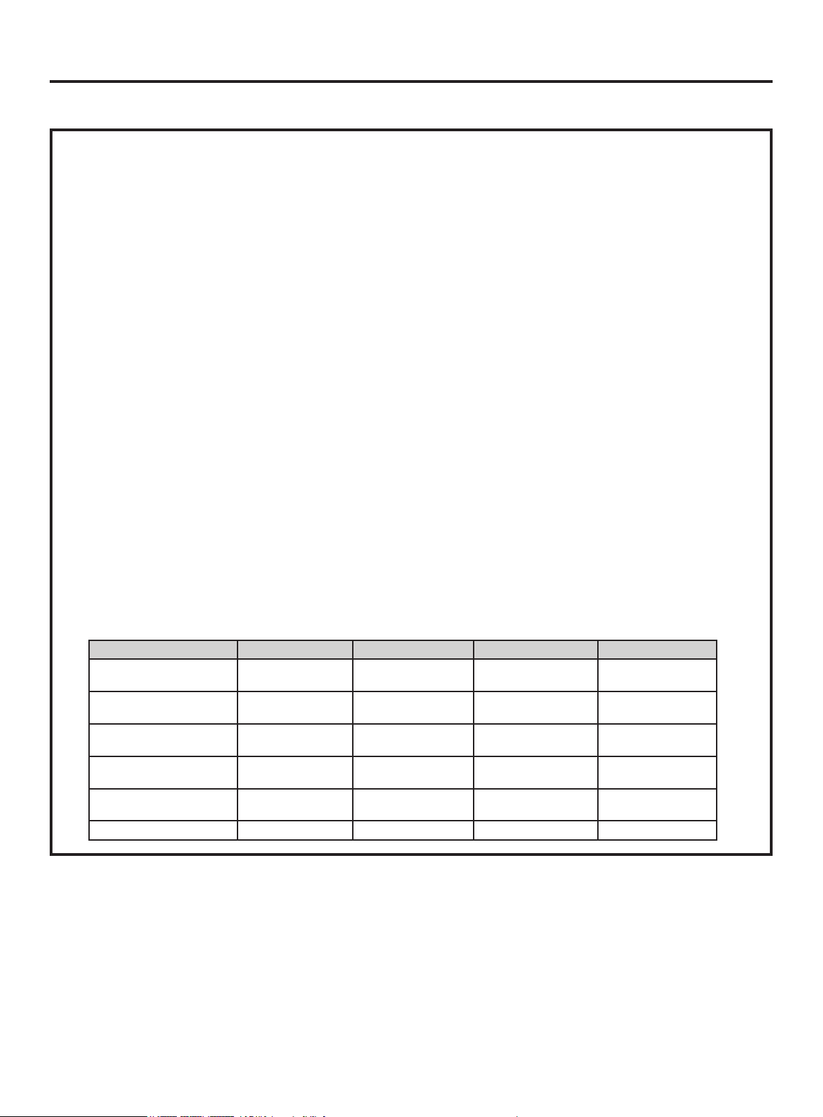
3. Heater Sizing: See table below
• Total system static should be less than .55” wc for
best performance
• Install the heater as close to the indoor unit air
OUTLET as possible.
• Order your heater size to fit your supply plenum as
best as possible to avoid bypass air.
• Run 230v supply from breaker panel to AUX heater
disconnect switch. Size line per local and national
electrical codes.
• Connect the control wires from the heater to the
Green AUX Heat plug at Heater P1 and P2
• Recommend set the Fan Static setting on your
wired controller above level 8 (see wired controller
instructions).
4. Indoor Unit PCB Dip Switches
To activity this function, must flip dip switch SW3_3.
Proper external static pressure setting is also very
important. (please refer to wired controller manual to
set the proper external static pressure)
5. Heater operating Conditions:
All 7 conditions below must be met for the Auxiliary
Heater port to be closed (“ON”)
1) Indoor temperature must be less than 3.6º (2ºC) than
controller set point
2) IDU didn’t reach its normal real temperature set point
and the ODU compressor has been running more
than 1 minute
3) Room temperature <77º (25ºC)
4) IDU fan motor is running
5) DIP switch SW2_3 is set to ON position
6) The ODU+IDU system is running in heat mode or
automatic heat mode
7) The IDU gas pipe sensor (coil) Tp<113º (45ºC)
Optional Special Application 1 - Auxiliary Heat
Indoor USYM09UCDSA USYM12UCDSA USYM18UCDSA USYM24UCDSA
Rated Cooling Capacity
Btu/hr
9,000 12,000 18,000 24000
Rated Heating Capacity
Btu/hr
10,000 13,000 19,000 25000
Voltage, Cycle, Phase
V/Hz/-
208-230/60/1 208-230/60/1 208-230/60/1 208-230/60/1
Airow (Turbo/High/Med/
Low/Quiet) CFM
424/353/294/235/176 494/424/353/294/235 735/635/541/470/400 835/735/635/541/470
Max. External Static
Pressure in.W.G (Pa)
0.6 (150) 0.6 (150) 0.6 (150) 0.6 (150)
Maximum Heater Size 1Kw 1Kw 1.5Kw 1.5Kw
Loading ...
Loading ...
Loading ...