Loading ...
Loading ...
Loading ...
31-5000493 Rev. 0 13
Optional Special Application 2 - Outside Air Damper Installation
Installation Instructions
Outside Air Damper Installation Instructions
Factory Supplied material:
• Wire harness (from accessory bag)
Required field supplied materials:
• 1 - 230v x 24v, 30va transformer
• 1 - 4” round, power open, spring closed, 24v air
damper
• 4’ -18-2 thermostat wire
• 1- 4X4 deep junction box (where required)
• 4 - 3/8” Romex clamps
• 1 – 3 Amp inline fuse with holder
Installation
1. Choose location for OSA to connect to unit. There
is a 4” round (plastic) flange on the side of the unit
available for OSA inlet. Remove flange, remove
center knock-out, rotate flange 180º and replace.
Connect 4” round damper/duct to flange.
2. Wire the primary side of the transformer to the 230v
power source for the indoor unit.
3. Mount damper so that it is secure. Connect duct
from outside air inlet to damper.
4. Mount the transformer on a secure location near the
control box cover. Mount inside a 4X4 junction box
where required by code.
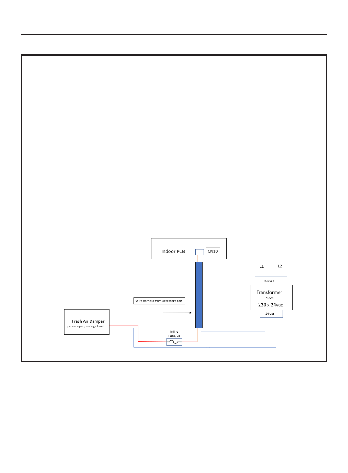
5. Take wire harness from indoor unit accessory bag
and connect the wire harness plug into the PCB
socket CN10.
6. Connect the other side of the wire harness to the
transformer 24v connection. Connect the other side
of the CN10 connection to the 3A inline fuse.
7. Connect the outlet end of the 3A inline fuse to the
actuator on the damper.
8. Connect common wire on the damper actuator to the
secondary common of the transformer. See wiring
diagram below
9. Secure and strap all wires.
10. In order to active OSA function, dipswitch SW1-6
must turn to the off position
11. For Continuously Fan operation (eg. BC Canada
code) applications, please set dipswitch SW3-1 to
ON
12. Follow the instructions that shipped with your wired
controller for controller dipswitch.
Loading ...
Loading ...
Loading ...