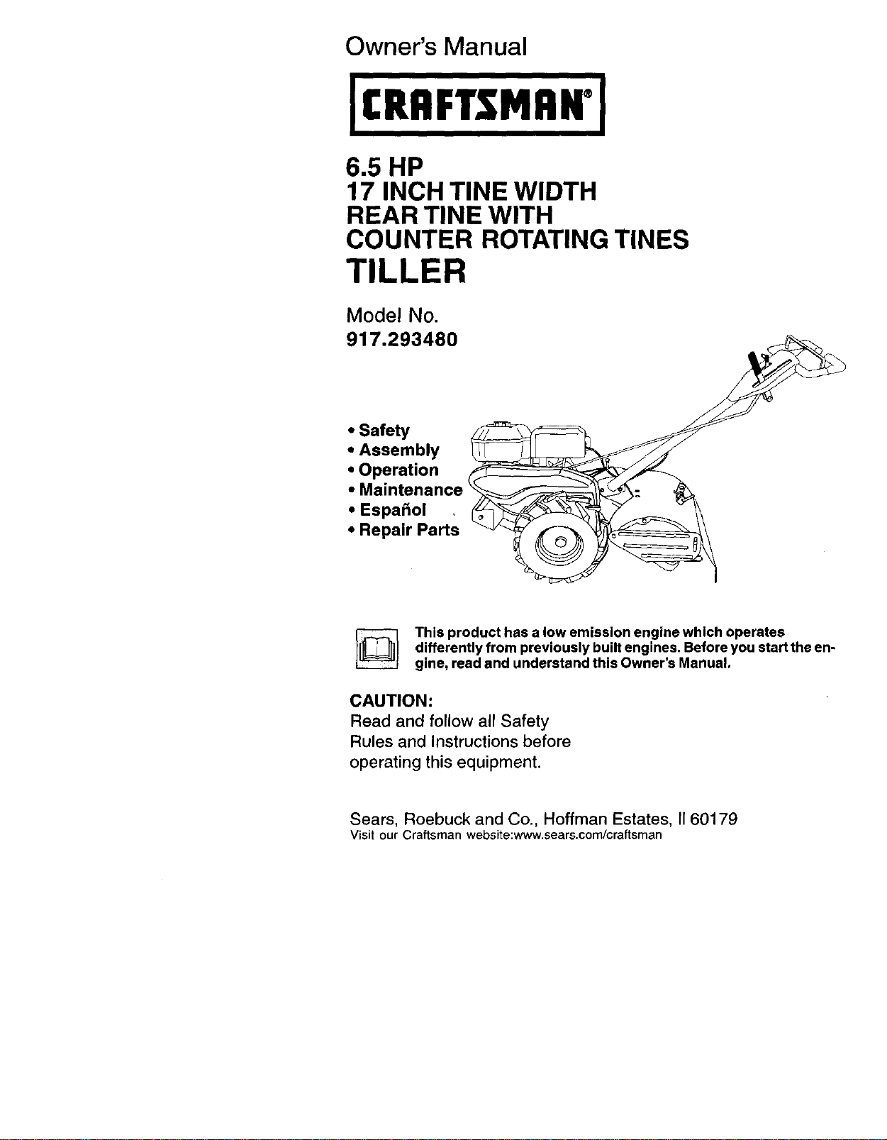
Owner's Manual
ICRAFTSMAWI
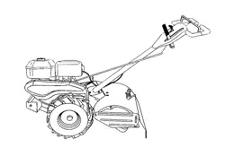
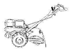
6.5 HP
17 INCH TINE WIDTH
REAR TINE WITH
COUNTER ROTATING TINES
TILLER
Model No.
917.293480
• Safety• Assembly
• Operation f
• Maintenance _ __'_- _
EspaSol
• Repair Parts
This product has a low emission engine which operates
differently from previously built engines. Before you start the en-
gine, read and understand this Owner's Manual.
CAUTION:
Read and follow all Safety
Rules and Instructions before
operating this equipment.
Sears, Roebuck and Co., Hoffman Estates, II 60179
Visit our Craftsman website:www.sears.com/craftsman
SafetyRules.........................................2
Warranty...............................................2
ProductSpecifications..........................4
Assembly..............................................5
Operation..............................................8
Maintenance.......................................13
ServiceandAdjustments....................15
Storage...............................................19
Troubleshooting.................................20
IllustratedPartsList............................42
PartsOrdering.....................BackCover
LIMITEDTWOYEARWARRANTYONCRAFTSMANTILLER
Fortwo(2)yearsfromdateof purchase, when this Craftsman Tiller is maintained,
lubricated, and tuned up according to the operating and maintenance instructions in
the owner's manual, Sears will repair free of charge any defect in material or workman-
ship.
This Warranty does not cover:
• Expendable items which become worn during normal use, such as tines, spark
plugs, air cleaners and belts.
• Repairs necessary because of operator abuse or negligence, including bent
crankshafts and the failure to maintain the equipment according to the instructions
contained in the owner's manual.
• If this Craftsman Tiller is used for commercial or rental purposes, this Warranty
applies for only thirty (30) days from the date of purchase.
Warranty service is available by returning the craftsman power mower to the nearest
sears service center/department in the united states. This warranty applies only while
this product is in use in the united states.
This Warranty gives you specific legal rights, and you may also have other rights which
vary from state to state.
SEARS, ROEBUCK AND CO., D/817WA, HOFFMAN ESTATES, IL 60179
IMPORTANT: This cutting machine is capable of amputating hands and feet and
throwing objects. Failure to observe the following safety instructions could result in
serious injury or death.
TRAINING
• Read the Owner's Manual carefully. Be
thoroughly familiar with the controls
and the proper use of the equipment.
Know how to stop the unit and disen-
gage the controls quickly.
• Never allow children to operate the
equipment. Never allow adults to
operate the equipment without proper
instruction.
• Keep the area of operation clear of all
persons, particularly small children,
and pets.
PREPARATION
• Thoroughly inspect the area where the
equipment is to be used and remove all
foreign objects.
2
Disengage all clutches and shift into
neutral before starting the engine
(motor).
Do not operate the equipment without
wearing adequate outer garments.
Wear footwear that will improve footing
on slippery surfaces.
Handle fuel with care; it is highly
flammable.
Use an approved fuel container.
Never add fuel to a running engine or
hot engine.
F{ILfuel tank outdoors with extreme
care, Never fill fuel tank indoors.
Replace gasoline cap securaly and
clean up spilled fuel before restarting.
Use extension cords and receptacles
as specified by the manufacturer for all
units with electric drive motors or
electric starting motors,
• Never attempt to make any adjustments
while the engine (motor) is running
(except where specifically recommend-
ed by manufacturer).
OPERATION
• Do not put hands or feet near or under
rotating parts.
• Exercise extreme caution when
operating on or crossing gravel drives,
walks, or roads. Stay alert for hidden
hazards or traffic. Do not carry passen-
gers.
,, After striking a foreign object, stop the
engine (motor), remove the wire from
the spark plug, thoroughly inspect the
tiller for any damage, and repair the
damage before restarting and operat-
ing the tiller.
• Exercise caution to avoid slipping or
falling.
• If the unit should start to vibrate
abnormally, step the engine (motor)
and check immediately for the cause.
Vibration is generally a warning of
trouble.
• Stop the engine (motor) when leaving
the operating position.
• Take all possible precautions when
leaving the machine unattended.
Disengage the tines, shift into neutral,
and stop the engine:
• Before cleaning, repairing, or inspect-
ing, shut off the engine and make
certain all moving parts have stopped.
Disconnect the spark plug wire, and
keep the wire away from the plug to
prevent accidental starting. Disconnect
the cord on electric motors.
• Do not run the engine indoors; exhaust
fumes are dangerous,
• Never operate the tiller without proper
guards, plates, or other safety protec-
tive devices in place.
• Keep children and pets away.
• Do not overload the machine capacity
by attempting to till too deep at too fast
a rate.
• Never operate the machine at high
speeds on slippery surfaces. Look
behind and use care when backing.
• Never allow bystanders near the unit.
• Use only attachments and accessories
approved by the manufacturer of the
tiller.
• Never operate the tiller without good
visibility or light.
• Be careful when tilling in hard ground.
The tines may catch in the ground and
propel the tiller forward, if this occurs,
let go of the handlebars and do not
restrain the machine.
MAINTENANCE AND STORAGE
• Keep machine, attachments, and
accessories in safe working condition.
• Check shear pins, engine mounting
bolts, and other bolts at frequent
intervals for proper tightness to be sure
the equipment is in safe working
condition.
• Never store the machine with fuel in the
fuel tank inside a building where
ignition sources are present, such as
hot water and space heaters, clothes
dryers, and the like. Allow the engine to
cool before storing in any enclosure.
• Always refer to the operator's guide
instructions for important details if the
tiller is to be stored for an extended
period.
ALook for this symbol to point out
important safety precautions, ttmeans
CAUTION!!! BECOME ALERT!!! YOUR
SAFETY IS INVOLVED.
-&,CAUTION: Always disconnect spark
plug wire and place wire where it cannot
contact spark plug in order to prevent
accidental starting when setting up,
transporting, adjusting or making repairs.
_WARNING: Engine exhaust, some of its
constituents, and certain vehicle compo-
nents contain or emit chemicals known to
the State of California to cause cancer
and birth defects or other reproductive
harm.
3
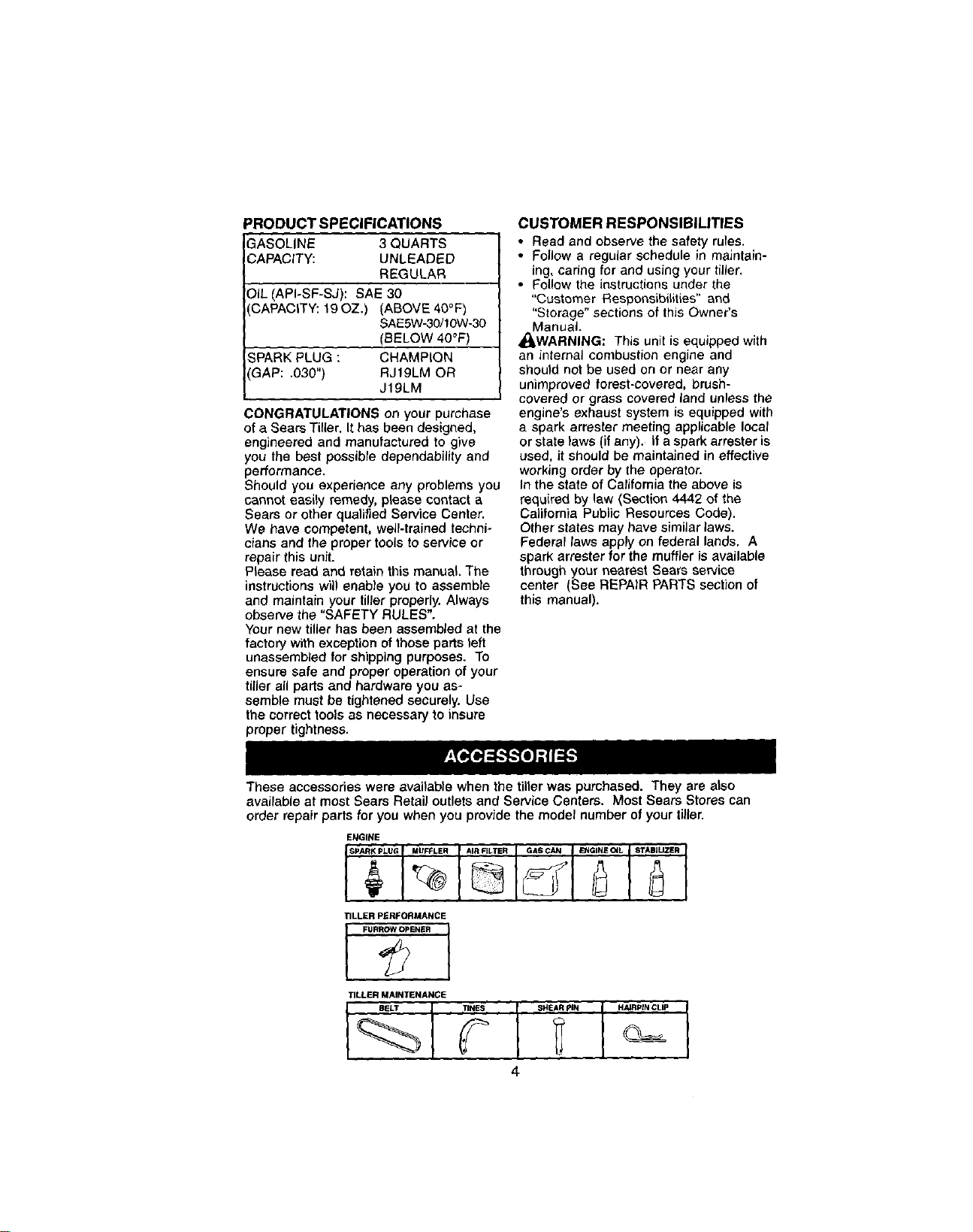
PRODUCT SPECIFICATIONS
GASOLINE 3 QUARTS
CAPACITY: UNLEADED
REGULAR
OIL (API-SF-SJ): SAE 30
CAPACITY: 19OZ.) (ABOVE 40°F)
SAE5W-30/t 0W-30
(BELOW 40°F)
_PARK PLUG : CHAMPION
GAP: .030") RJt9LM OR
J19LM
CONGRATULATIONS on your purchase
of a Sears Tiller. It has been designed,
engineered and manufactured to give
you the best possibre dependability and
performance.
Should you experience any problems you
cannot easily remedy, please contact a
Sears or other qualified Service Center.
We have competent, well-trained techni-
cians and the proper tools to service or
repair this unit.
Please read and retain this manual. The
instructions will enable you to assemble
and maintain your tiller properly. Always
observe the "SAFETY RULES".
Your new tiller has been assembled at the
factory with exception of those parts left
unassembled for shipping purposes. To
ensure safe and proper operation of your
tiller all pads and hardware you as-
semble must be tightened securely. Use
the correct tools as necessary to insure
proper tightness.
CUSTOMER RESPONSIBILITIES
• Read and observe the safety rules.
• Follow a regular schedule in maintain-
ing, caring for and using your tiller.
• Follow the instructions under the
"Customer Responsibilities" and
"Storage" sections of this Owner's
Manual.
4_WARNING: This unit is equipped with
an internal combustion engine and
should not be used on or near any
unimproved forest-covered, brush-
covered or grass covered land unless the
engine's exhaust system is equipped with
a spark arrester meeting applicable local
or state taws (if any). If a spark arrester is
used, it should be maintained in effective
working order by the operator.
In the state of California the above is
required by law (Section 4442 of the
California Public Resources Code).
Other states may have similar laws.
Federal taws apply on federal lands. A
spark arrester for the muffler is available
through your nearest Sears service
center (See REPAIR PARTS section of
this manual).
These accessories were available when the tiller was purchased. They are also
avairable at most Sears Retail outlets and Service Centers. Most Sears Stores can
order repair parts for you when you provide the model number of your tiller.
ENGINE
TILLER PERFORMANCE
I FUR_ISNSR
TILLER MAINTENANCE
4
Your new tiller has been assembled at the
factory with exception of those parts left
unassembled for shipping purposes. To
ensure safe and proper operation of your
tiller all parts and hardware you assemble
must be tightened securely. Use the
correct tools as necessary to insure
proper tightness.
TOOLS REQUIRED FOR ASSEMBLY
A socket wrench set will make assembly
easier. Standard wrench sizes are listed.
(1) Utility knife
(1) Wire cutter
(t) Tire pressure gauge
(1) Screwdriver
(1) Pair of pliers
(t) 9/16" wrench
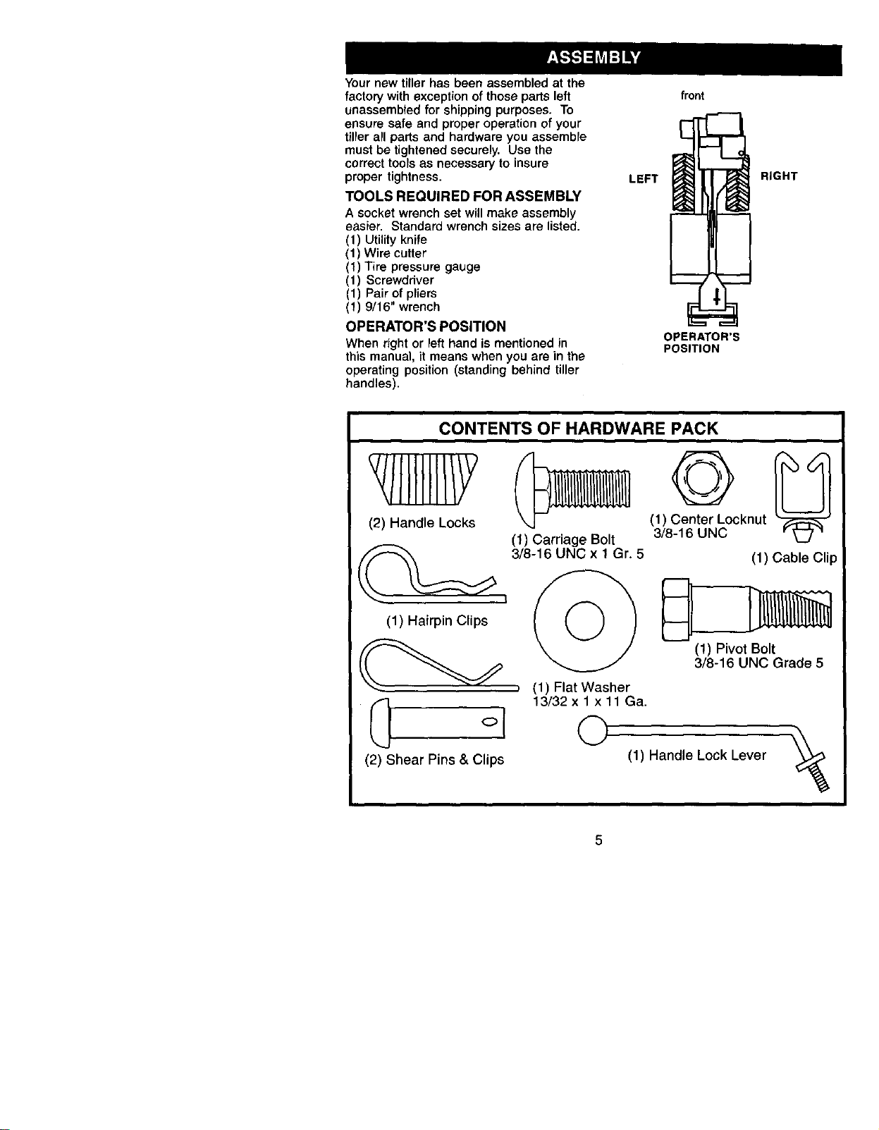
OPERATOR'S POSITION
When right or left hand is mentioned in
this manual, it means when you are in the
operating position (standing behind tiller
handles).
LEFT
front
OPERATOR'S
POSITION
RIGHT
CONTENTS OF HARDWARE PACK
(2) Handle Locks
(1) Hairpin Clips
(2) Shear Pins & Clips
(_ (1) Center Locknut
(1) Carriage Bolt 3/8-16 UNC
3/8-16 UNC x 1 Gr. 5 (1) Cable Clip
(!) Pivot Bolt
3/8-16 UNC Grade 5
, (1) Flat Washer
!3/32 x 1 x 11 Qa.
©
(1) Handle Lock Lever
%
5
UNPACKING CARTON
_LCAUTION: Be careful of exposed
staples when handling or disposing of
cartoning material.
IMPORTANT: When unpacking and
assembling tiller, be careful of exposed
staples when handling or disposing of
cartoning material.
1. While holding handle assembly, cut
cable ties securing handre assembly
to top frame. Let handle assembly
rest on tiller.
2. Remove top frame of carton.
3. Slowly ease handle assembly up and
place on top of carton.
4. Cut down right hand front and right
hand rear corners of carton, lay side
carton wall down.
5. Remove packing material from handle
assembly.
6. Separate shift rod from handle
assembly.
te
mbly
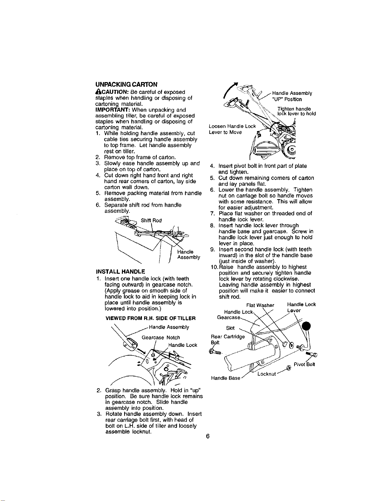
INSTALL HANDLE
1. Insert one handle lock (with teeth
facing outward) in gearcase notch,
(Apply grease on smooth side of
handle lock to aid in keeping lock in
place until handJe assembly is
lowered into position,)
VIEWED FROM R.H. SIDE OF TILLER
..ond,eA.somb,y
arcase Notch
ndle Lock
2. Grasp handle assembly. Hold in "up"
position. Be sure handle lock remains
in gearcase notch. Slide handle
assembly into position.
3. Rotate handle assembly down. Insert
rear carriage bolt first, with head of
bolt on L.H. side of tiller and loosely
assemble Iocknut.
::::_'.,_;_..;2J HandleAssembly
":::::,_..'._"UP" Position
"_'_'_ '"?_'_,_ Tighten handle
--_.:"_%'ock lever10hold
Loese
to Move :_
Lever to Move
4. Insert pivot bolt in front part of plate
and tighten.
5. Cut down remaining corners of carton
and lay panels flat.
6. Lower the handle assembly. Tighten
nut on carriage bolt so handre moves
with some resistance. This will allow
for easier adLustment.
7. Place flat washer on threaded end of
handle lock lever.
8. Insert handle lock lever through
handle base and gearcase. Screw in
handle lock lever just enough to hold
lever in place.
9. Insert second handle lock (with teeth
inward) in the slot of the handle base
(just inside of washer).
10.Raise handle assembly to highest
position and securely tighten handle
lock lever by rotating clockwise.
Leaving handle assembly in highest
position will make it easier to connect
shift rod.
Flat Washer Handle Lock
Handle Lock, _ Lever
Gearease-_ /._j
Rear Cartridge _ \ "_/
\\ _rc'_v_ _ PivotBolt
HandleBas_B_e_c_mt f
6
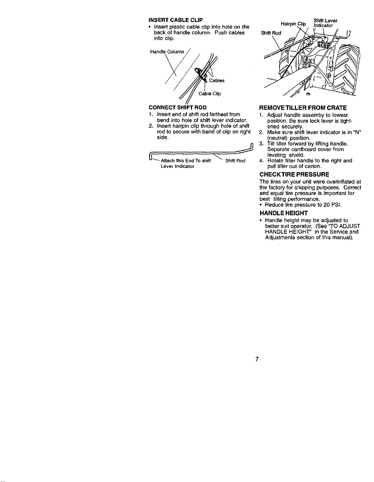
INSERT CABLE CLIP
• Insert plastic cable clip into hole on the
back of handle column. Push cables
into clip.
Handle Column
Shift Rod
Indicator
Cables
Cable Clip
CONNECT SHIFT ROD
1. Insed end of shift rod farthest from
bend into hole of shift lever indicator.
2. Insert hairpin clip through hole of shift
rod to secure with bend of clip on right
side.
_'_Attach thisEnd Toshift_ Shift Rod
Lever Indicator
REMOVE TILLER FROM CRATE
1. Adjust handle assemby to lowest
position. Be sure lock lever is tight-
ened securely.
2. Make sure shift lever indicator is in "N"
(neutral) position.
3. Tilt tiller forward by lifting handle.
Separate cardboard cover from
leveling shield.
4. Rotate tiller handle to the right and
pull tiller out of carton.
CHECKTIRE PRESSURE
The tires on your unit were overinflated at
the factory for shipping purposes. Correct
and equal tire pressure is important for
best tilling performance.
• Reduce tire pressure to 20 PSI.
HANDLE HEIGHT
• Handle height may be adjusted to
better suit operator. (See "TO ADJUST
HANDLE HEIGHT" in the Service and
Adjustments section of this manual).
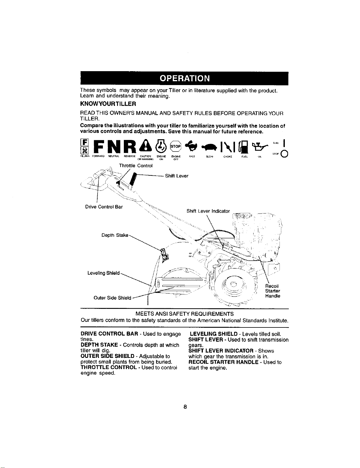
ThesesymbolsmayappearonyourTiller or in literature supplied with the product.
Learn and understand their meaning.
KNOWYOURTILLER
READ THIS OWNER'S MANUAL AND SAFETY RULES BEFORE OPERATING YOUR
TILLER.
Compare the illustrations with your tiller to familiarize yourself with the location of
various controls and adjustments, Save this manual for future reference,
TILLING FORWARD NEUTRAL R£VERSE CAUTK_N ENGINE ENGINE FAST SLOW _E FUEL OIL SlOP O
OR WA_ING ON OFF
Throttle Control
Shift Lever
Drive Control Bar "_
-. _. Shift Lever ndcater
Depth Stake--._ "_. f _': I ! - '
//]
Leveling Shield_ / / "'/'_/ ....:: 'ih_I()':"" ': '_"\I "
"7"/iLl ' __I . f_f/t' L _; ;1 Recoil
_. __ _'_ Starter
Outer Side Shield/_ _ _ _--; Handle
MEETS ANSI SAFETY REQUIREMENTS
Our tillers conform to the safety standards of the American National Standards Institute,
DRIVE CONTROL BAR - Used to engage
tines.
DEPTH STAKE - Controls depth at which
tiller will dig.
OUTER SIDE SHIELD - Adjustable to
protect small plants from being buried.
THROTTLE CONTROL - Used to control
engine speed.
LEVELING SHIELD - Levels tilled soil.
SHIFT LEVER - Used to shift transmission
gears.
SHIFT LEVER INDICATOR - Shows
which gear the transmission is in.
RECOIL STARTER HANDLE - Used to
start the engine.
Theoperationofanytiller can result in foreign objects thrown into the eyes,
which can result in severe eye damage. Always wear safety glasses or eye
shields before starting your tiller and while tilling. We recommend a wide
vision safety mask over spectacles or standard safety grasses.
HOWTO USEYOURTILLER
Know how to operate all controls before
adding fuel and oil or attempting to start
engine.
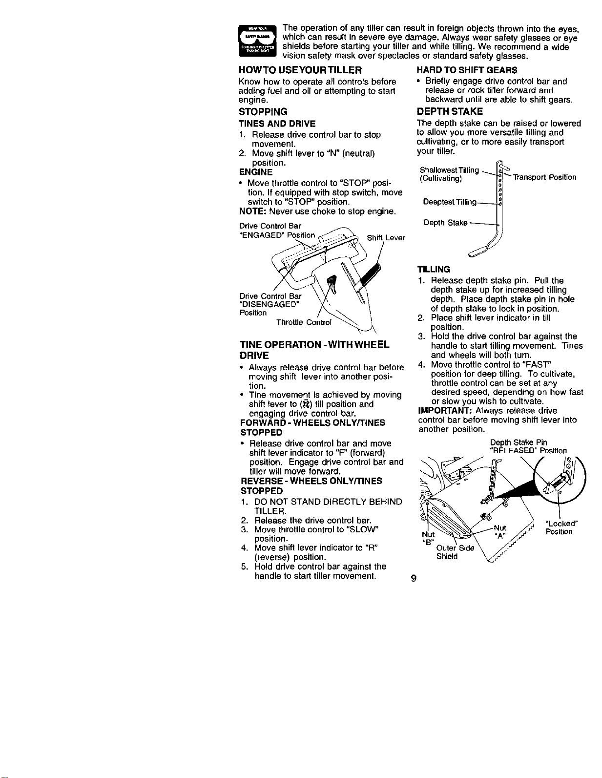
STOPPING
TINES AND DRIVE
1. Release drive control bar to stop
movement.
2. Move shift lever to "N" (neutral)
position.
ENGINE
• Move throttle control to "STOP" posi-
tion. If equipped with stop switch, move
switch to "STOP" position.
NOTE: Never use choke to stop engine.
DriveControlBar
"ENGAGED"Position .-_-:::,_ ShiftLever
Drive ControlBar X \\ /
"DISENGAGED" '\ "_/
Position _._ /
ThrottleControl _
TINE OPERATION -WITH WHEEL
DRIVE
• Always release drive control bar before
moving shift lever into another posi-
tion.
• Tine movement is achieved by moving
shift lever to (_) till position and
engaging drive control bar.
FORWARD - WHEELS ONLY/TINES
STOPPED
• Release drive control bar and move
shift lever indicator to "F" (forward)
position. Engage drive control bar and
tiller will move forward.
REVERSE - WHEELS ONLY/TINES
STOPPED
1. DO NOT STAND DIRECTLY BEHIND
TILLER.
2. Release the drive control bar.
3. Move throttle control to "SLOW"
position.
4. Move shift lever indicator to "R"
(reverse) position.
5. Hold drive control bar against the
handle to start tiller movement.
HARD TO SHIFT GEARS
• Briefly engage drive control bar and
release or rock tiller forward and
backward until are able to shift gears.
DEPTH STAKE
The depth stake can be raised or lowered
to allow you more versatile tilling and
cultivating, or to more easily transport
your tiller.
Shallowest Tilling
(Cultivating)
Deeptest Tilling_
De_h S_ke_-
Transport Position
J
TILLING
1. Release depth stake pin. Pull the
depth stake up for increased tilling
depth. Place depth stake pin in hole
of depth stake to lock in position.
2. Place shift lever indicator in till
position.
3. Hold the drive control bar against the
handle to start tilling movement. Tines
and wheels will both turn.
4. Move throttle control to"FAST"
position for deep tilling. To cultivate,
throttle control can be set at any
desired speed, depending on how fast
or slow you wish to cultivate.
IMPORTANT: Always release drive
control bar before moving shift lever into
another position.
DepthStake Pin
"RELEASED" Position
Nut
Shield
"Locked"
Position
TURNING
1, Release the drive control bar.
2, Move throttle control to "SLOW"
position.
3. Place shift lever indicator in "F"
(forward) position. Tines will not tum.
4. Lift handle to raise tines out of ground,
5, Swing the handle in the opposite
direction you wish to turn, being
careful to keep feet and legs away
from tines.
6. When you have completed your turn-
around, release the drive control bar
and lower handle, Place shift lever in
(till) position and move throttle control
to desired speed. To begin tilling,
hold drive control bar against the
handle.
OUTER SIDE SHIELDS
The back edges of the outer side shields
are slotted so that the shields can be
raised for deep tilling and lowered for
shallow tilling to protect small plants from
being buried.
1. Loosen nut "A" in slot and nut "B".
2. Move shield to desired position (both
sides),
3. Retighten nuts.
TOTRANSPORT
_I,CAUTION: Before lifting or transporting,
allow tiller engine and muffler to cool.
Disconnect spark plug wire. Drain
gasoline from fuel tank.
AROUND THE YARD
1. Release the depth stake pin. Move
the depth stake down to the top hore
for transporting the tiller. Place depth
stake pin in hole of depth stake to lock
in position. This prevents tines from
scuffing the ground.
2. Place shift lever indicator in "F"
(forward) position for transporting.
3. Hold the drive control bar against the
handle to start tiller movement. Tines
will not turn.
4. Move throttle control to desired speed.
AROUND TOWN
1. Disconnect spark plug wire.
2. Drain fuel tank.
3. Transport in upright position to
prevent oil leakage.
BEFORE STARTING ENGINE
IMPORTANT: Be very careful not to allow
dirt to enter the engine when checking or
adding oil or fuel. Use clean oil and fuel
and store in approved, clean, covered
containers, use clean fill funnels.
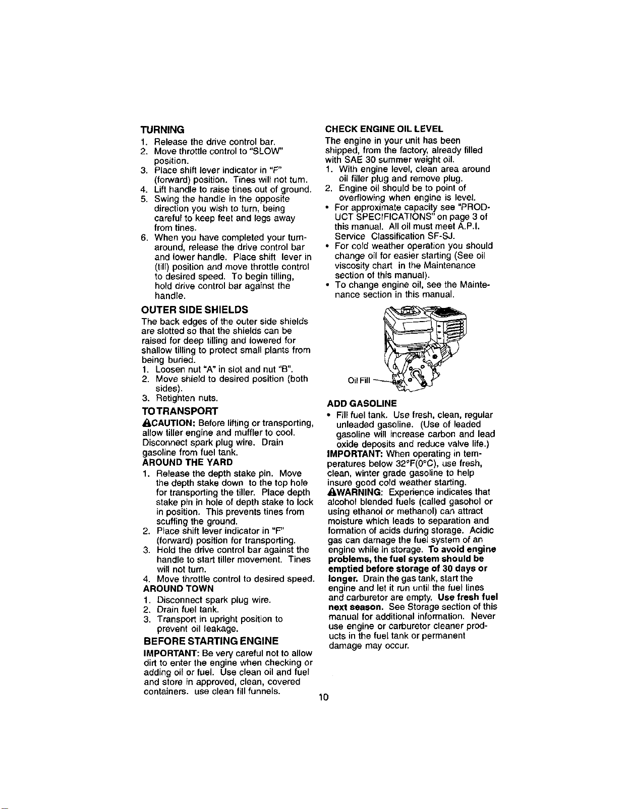
CHECK ENGINE OIL LEVEL
The engine in your unit has been
shipped, from the factory, already filled
with BAE 30 summer weight oil.
1. With engine level, clean area around
oU filler plug and remove plug,
2, Engine oil should be to point of
overflowing when engine is level.
• For approximate capacity see "PROD.
UCT SPECIFICATrONS" on page 3 of
this manual. All oil must meet A.P.I,
Service Classification SF-SJ.
• For cold weather operation you should
change oil for easier starting (See oil
viscosity chart in the Maintenance
section of this manual).
• To change engine oil, see the Mainte-
nance section in this manual.
Oil Fill _
ADD GASOLINE
• Fill fuel tank, Use fresh, clean, regular
unleaded gasoline. (Use of leaded
gasoline will increase carbon and lead
oxide deposits and reduce valve life.)
IMPORTANT: When operating in tem-
peratures below 32°F(0°C), use fresh,
clean, winter grade gasoline to help
insure good cold weather starting.
_WARNING: Experience indicates that
alcohol blended fuels (called gasohol or
using ethanol or methanol) can attract
moisture which leads to separation and
formation of acids during storage. Acidic
gas can damage the fuel system of an
engine while in storage. To avoid engine
problems, the fuel system should be
emptied before storage of 30 days or
longer, Drain the gas tank, start the
engine and let it run until the fuel lines
and carburetor are empty. Use fresh fuel
next season. Bee Storage section of this
manual for additional information. Never
use engine or carburetor cleaner prod-
ucts in the fuel tank or permanent
damage may occur.
10
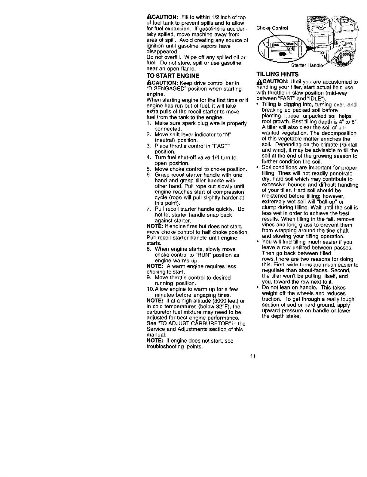
_,CAUTION: Fillto within 1/2inch of top
of fuel tank to prevent spills and to allow
for fuel expansion. If gasoline is acciden-
tally spilled, move machine away from
area of spill. Avoid creating any soume of
ignition until gasoline vapors have
disappeared.
Do not overfill. Wipe off any spilled oil or
fuel. Do not store, spill or use gasoline
near an open flame.
TO START ENGINE
ACAUTION: Keep drive control bar in
"DISENGAGED" position when starting
engine.
When starting engine for the first time or if
engine has run out of fuel, it will take
extra pulls of the recoil starter to move
fuel from the tank to the engine.
1. Make sure spark plug wire is properly
connected.
2. Move shift lever indicator to "N"
(neutral) position.
3. Place throttle control in "FAST"
position.
4. Turn fuel shut-off valve 1/4 turn to
open position.
5. Move choke control to choke position.
6. Grasp recoil starter handle with one
hand and grasp tiller handle with
other hand. Pull rope out slowly until
engine reaches start of compression
cycle (rope will pull slightly harder at
this point).
7. Pull recoil starter handle quickly. Do
not let starter handle snap back
against starter.
NOTE: If engine fires but does not start,
move choke control to half choke position.
Pull recoil starter handle until engine
starts.
8. When engine starts, slowly move
choke control to "RUN" position as
engine warms up.
NOTE: A warm engine requires less
choking to start.
9. Move throttle control to desired
running position.
10.Allow engine to warm up for a few
minutes before engaging tines.
NOTE: If at a high altitude (3000 feet) or
in cold temperatures (below 32°F), the
carburetor fuel mixture may need to be
adjusted for best engine performance.
See "3"0 ADJUST CARBURETOR" in the
Service and Adjustments section of this
manual.
NOTE: If engine does not start, see
troubleshooting points.
ChokeControl __>--_.s )_ __ ___
StarterHandle/ "_
11
TILLING HINTS
_aCAUTION: Until you are accustomed to
ndling your tiner, start actual field use
with throttle in slow position (mid-way
between "FAST" and "IDLE").
• Tilling is digging into, turning over, and
breaking up packed soil before
planting. Loose, unpacked soil helps
root growth. Best tilling depth is4" to 6".
A tiller will also clear the soil of un-
wanted vegetation. The decomposition
of this vegetable matter enriches the
soil. Depending on the climate (rainfall
and wind), it may be advisable to till the
soil at the end of the growing season to
further condition the soil.
• Soil conditions are important for proper
tilling. Tines will not readily penetrate
dry, hard soil which may contribute to
excessive bounce and difficult handling
of your tiller. Hard soil should be
moistened before tilling; however,
extremely wet soil will "ball-up" or
clump during tilling. Wait until the soil is
less wet in order to achieve the best
results. When tilling in the fall, remove
vines and long grass to prevent them
from wrapping around the tine shaft
and slowing your tilling operation.
• You will find tilling much easier if you
leave a row untilled between passes.
Then go back between tilled
rows.There are two reasons for doing
this. First, wide turns are much easier to
negotiate than about-faces. Second,
the tiller won't be pulling itself, and
you, toward the row next to it.
• Do not lean on handle. This takes
weight off the wheels and reduces
traction. To get through a really tough
section of sod or hard ground, apply
upward pressure on handle or lower
the depth stake.
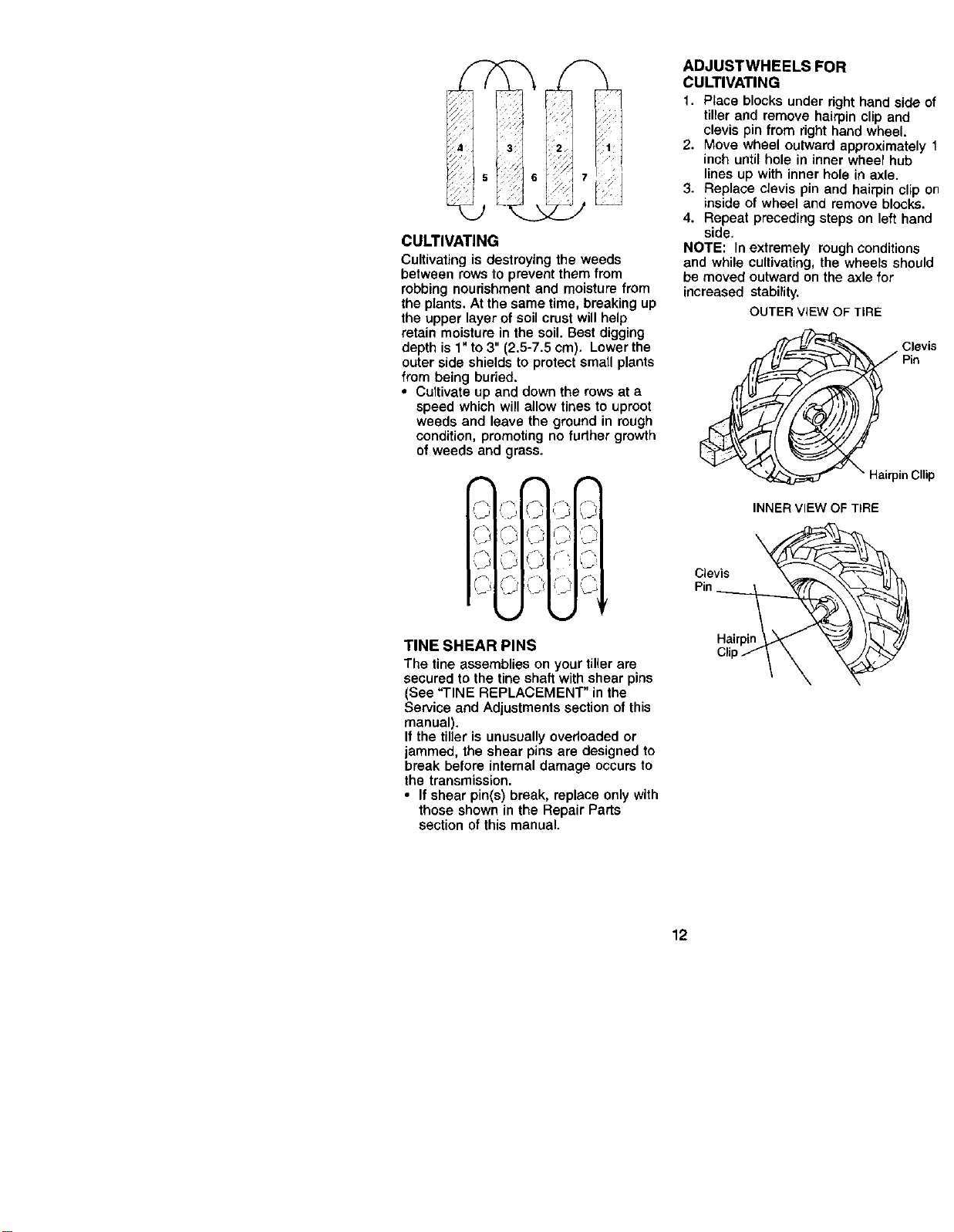
CULTIVATING
Cultivating is destroying the weeds
between rows to prevent them from
robbing nourishment and moisture from
the plants, At the same time, breaking up
the upper layer of soil crust will help
retain moisture in the soil. Best digging
depth is 1" to 3" (2.5-7,5 cm). Lower the
outer side shields to protect small plants
from being buried.
• Cultivate up and down the rows at a
speed which will allow tines to uproot
weeds and leave the ground in rough
condition, promoting no fudher growth
of weeds and grass.
!
.... _j \-
TINE SHEAR PINS
The tine assemblies on your tiller are
secured to the tine shaft with shear pins
(See "TINE REPLACEMENT" in the
Service and Adjustments section of this
manual).
It the tiller is unusually overloaded or
jammed, the shear pins are designed to
break before internal damage occurs to
the transmission.
• If shear pin(s) break, replace only with
those shown in the Repair Parts
section of this manual.
ADJUSTWHEELS FOR
CULTIVATING
1. Place blocks under right hand side of
tiller and remove hairpin clip and
clevis pin from right hand wheel.
2. Move wheel outward approximately 1
inch until hole in inner wheel hub
lines up with inner hole in axle.
3. Replace clevis pin and hairpin clip on
inside of wheel and remove blocks.
4. Repeat preceding steps on left hand
side.
NOTE: In extremely rough conditions
and while cultivating, the wheels should
be moved outward on the axle for
increased stability.
OUTER VIEW OF TIRE
Clevis
Pin
in Cllip
INNER VIEW OF TIRE
v
Pin ___ _
Hairpin
/\
12
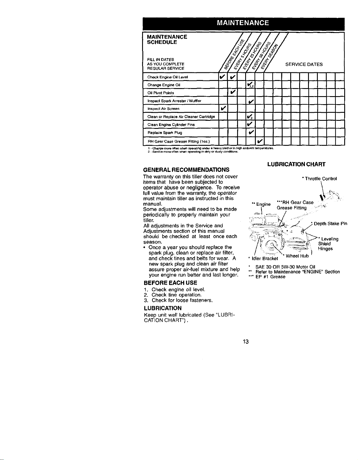
MAtNTENANCE
SCHEDULE
SE°V, OATES
Ko
FILL IN DATES
AS YOU COMPLETE
REGULAR SERVICE
Check Engine Oil Level
Change Engine Oil
Oil Pivot Points I_
Inspect Spark Arrester / Muffler
inspect Air Screen if
Clean or Replace Air Cleaner Cartridge 1_2
Clean Engine Cylinder Fins _ ,
Replace Spark Plug I_
RH Gear Case Grease Fitting (1oz.)
1 Cha_lge morG o_e:l Wh_f i Op_'Gtif_g I_ a hoavy IOa(_ or _ }dgh _uTil_ t_r_utes.
2. SeMce more often wt_en opera,rig in dirty or dusty cop.tilt lcn S
GENERAL RECOMMENDATIONS
The warranty on this tiller does not cover
items that have been subjected to
operator abuse or negligence. To receive
full value from the warranty, the operator
must maintain tiller as instructed in this
manual.
Some adiustments will need to be made
periodically to properly maintain your
tiller.
All adjustments in the Service and
Adjustments section of this manual
should be checked at least once each
season.
• Once a year you should replace the
spark plug, clean or replace air filter,
and check tines and belts for wear. A
new spark plug and clean air filter
assure proper air-fuel mixture and help
your engine run better and last longer.
BEFORE EACH USE
1. Check engine oil level.
2. Check line operation.
3. Check for loose fasteners.
LUBRICATION
Keep unit well lubricated (See "LUBRI-
CATION CHART").
LUBRICATION CHART
* Throttle Control
<il _
** Engne ***RH Gear Case .
| Grease Fitting
il I [LI ° • .
Oe0t.Sta e io
/. i_\_7 _Hinges
. ,d/lerBracke;X" Wheal Hub )
SAE 30 OR 5W-30 Motor Oil
** Refer to Maintenance "ENGINE" Section
*** EP #1 Grease
13
_CAUTION: Disconnect spark plug wire
before performing any maintenance
(except carburetor adjustment) to prevent
accidental starting of engine.
Prevent fires! Keep the engine free of
grass, leaves, spilled oil, or fuel. Remove
fuel from tank before tipping unit for
maintenance. Clean muffler area of all
grass, dirt, and debris.
Do not touch hot muffler or cylinder fins
as contact may cause burns.
ENGINE
LUBRICATION
Use only high quality detergent oil rated
with API service classification SF-SJ.
Select the oil's SAE viscosity grade
according to your expected temperature.
I I
NOTE: Although multi-viscosity oils (5W-
30, 10W-30, etc.) improve starting in cold
weather, these multi-viscosity oils will
result in increased oil consumption when
used above 32°F (0°C). Check your
engine oil level more frequently to avoid
possible engine damage from running
low on oil
Change the oil after every 25 hours of
operation or at least once a year if the
tiller is not used for 25 hours in one year.
Check the crankcase oil level before
starting the engine and after each five (5)
hours of continuous use. Add SAE 30
motor oil or equivalent. Tighten oil filler
plug securely each time you check the oil
level.
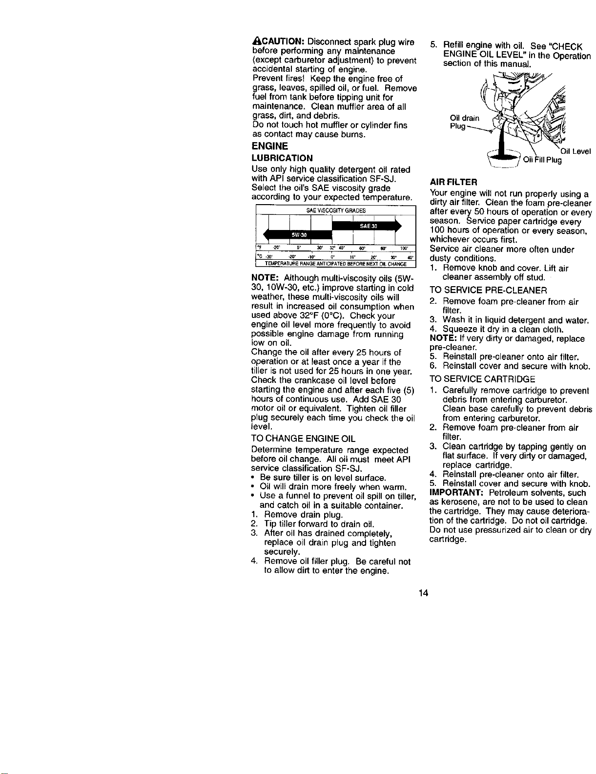
TO CHANGE ENGINE OIL
Determine temperature range expected
before oil change. All oil must meet API
service classification SF-SJ.
• Be sure tiller is on level surface.
• Oil will drain more freely when warm.
• Use a funnel to prevent oil spill on tiller,
and catch oil in a suitable container.
1, Remove drain plug.
2. Tip tiller forward to drain oil.
3. After oil has drained completely,
replace oil drain plug and tighten
securely.
4. Remove oil filler plug. Be careful not
to allow dirt to enter the engine.
5. Refill engine with oil. See "CHECK
ENGINE OIL LEVEL" in the Operation
section of this manual.
Oildrain _-
Plug._. _€€_
ilLevel
OilFillPlug
AIR FILTER
Your engine will not run properly using a
dirty air filter. Clean the foam pre-cleaner
after every 50 hours of operation or every
season. Service paper cartridge every
100 hours of operation or every season,
whichever occurs first.
Service air cleaner more often under
dusty conditions.
1. Remove knob and cover. Lift air
cleaner assembly off stud.
TO SERVICE PRE-CLEANER
2. Remove foam pre-cleaner from air
filter.
3. Wash it in liquid detergent and water.
4. Squeeze it dry in a clean cloth.
NOTE: If very dirty or damaged, replace
pre-cleaner.
5. Reinstall pre-cleaner onto air filter.
6. Reinstall cover and secure with knob.
TO SERVICE CARTRIDGE
1. Carefully remove cartridge to prevent
debris from entering carburetor.
Clean base carefully to prevent debris
from entering carburetor.
2. Remove foam preocleaner from air
filter.
3. Clean cartridge by tapping gently on
fiat surface. If very dirty or damaged,
replace cartridge.
4. Reinstall pre-cleaner onto air filter.
5. Reinstall cover and secure with knob.
IMPORTANT; Petroleum solvents, such
as kerosene, are not to be used to clean
the cartridge. They may cause deteriora-
tion of the cartridge. Do not oil cartridge.
Do not use pressurized air to clean or dry
cartridge.
14
_Cover Knob
Cover_
Stud
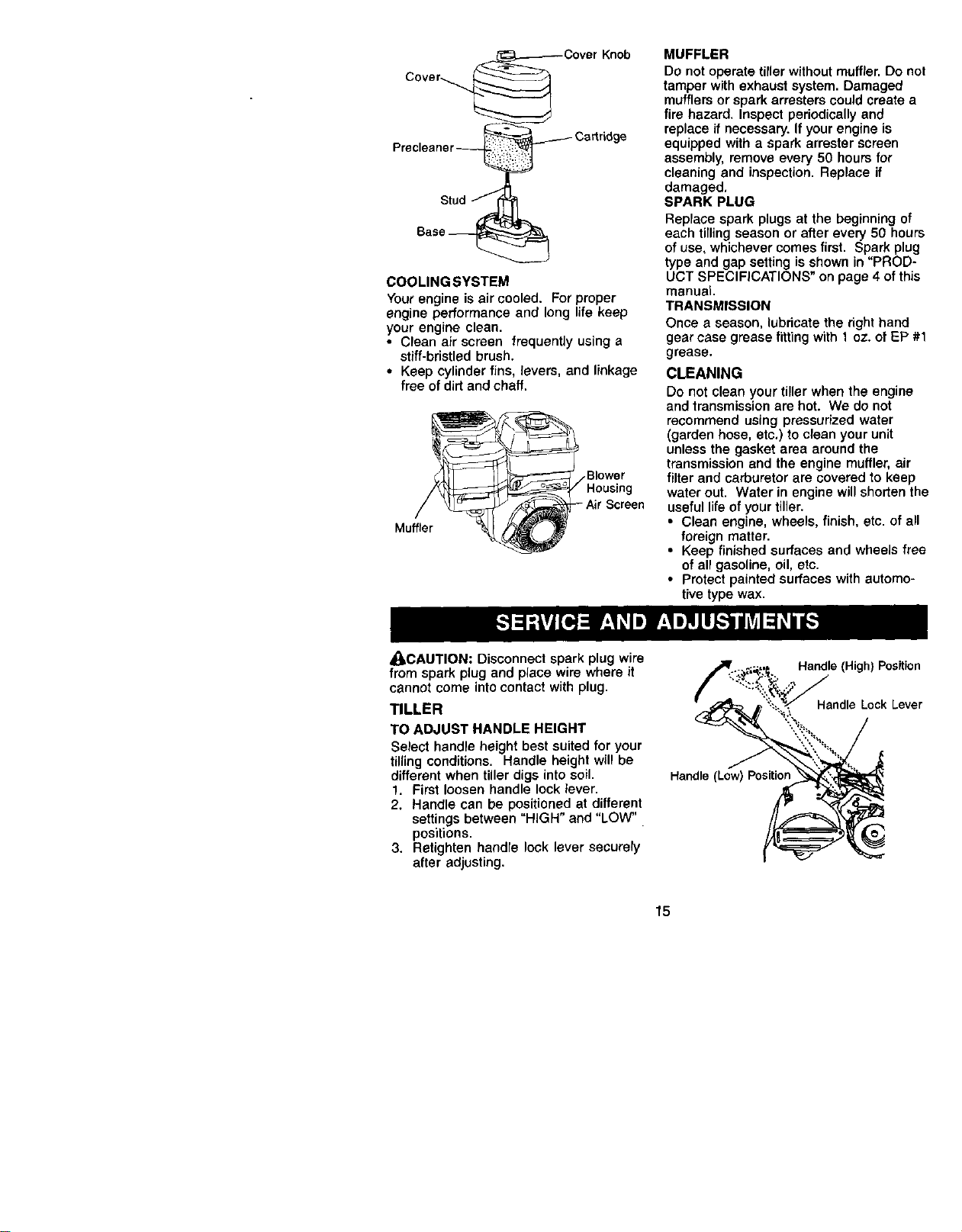
COOLING SYSTEM
Your engine is air cooled. For proper
engine performance and long life keep
your engine clean.
• Clean air screen frequently using a
stiff-bristled brush.
• Keep cylinder fins, levers, and linkage
free of dirt and chaff.
Blower
Muffler
MUFFLER
DO not operate tiller without muffler. Do not
tamper with exhaust system. Damaged
mufflers or spark arrestere could create a
fire hazard. Inspect periodically and
replace if necessary. If your engine is
equipped with a spark arrester screen
assembly, remove every 50 hours for
cleaning and inspection. Replace if
damaged,
SPARK PLUG
Replace spark plugs at the beginning of
each tilling season or after every 50 hours
of use+ whichever comes first. Spark plug
type and gap setting is shown in "PROD-
UCT SPECIFICATIONS" on page 4 of this
manual
TRANSMISSION
Once a season, lubricate the right hand
gear case grease fitting with 1 oz. of EP #1
grease.
CLEANING
Do not clean your tiller when the engine
and transmission are hot. We do not
recommend using pressurized water
(garden hose, etc.) to clean your unit
unless the gasket area around the
transmission and the engine muffler, air
filter and carburetor are covered to keep
water out. Water in engine will shorten the
useful lifeof your tiller.
• Clean engine, wheels, finish, etc. of all
foreign matter.
• Keep finished surfaces and wheels free
of all gasoline, oil, etc.
• Protect painted surfaces with automo-
tive type wax.
_CAUTION: Disconnect spark plug wire
from spark plug and place wire where it
cannot come intocontact with plug.
TILLER
TO ADJUST HANDLE HEIGHT
Select handle height best suited for your
tilling conditions. Handle height will be
different when tiller digs into soil.
1. First loosen handle lock lever.
2. Handle can be positioned at different
settings between "HIGH" and "LOW"
positions.
3. Retighten handre lock lever securely
after adjusting.
Handle (Low) Position
Handle (High) Position
Handle Lock Lever
@
15
TIRE CARE
_kCAUTION: When mounting tires, unless
beads are seated, overinflation can
cause an explosion.
• Maintain 20 pounds of tire pressure. If
tire pressures are not equal, tiller will
pull to one side.
• Keep tires free of gasoline or oil which
can damage rubber.
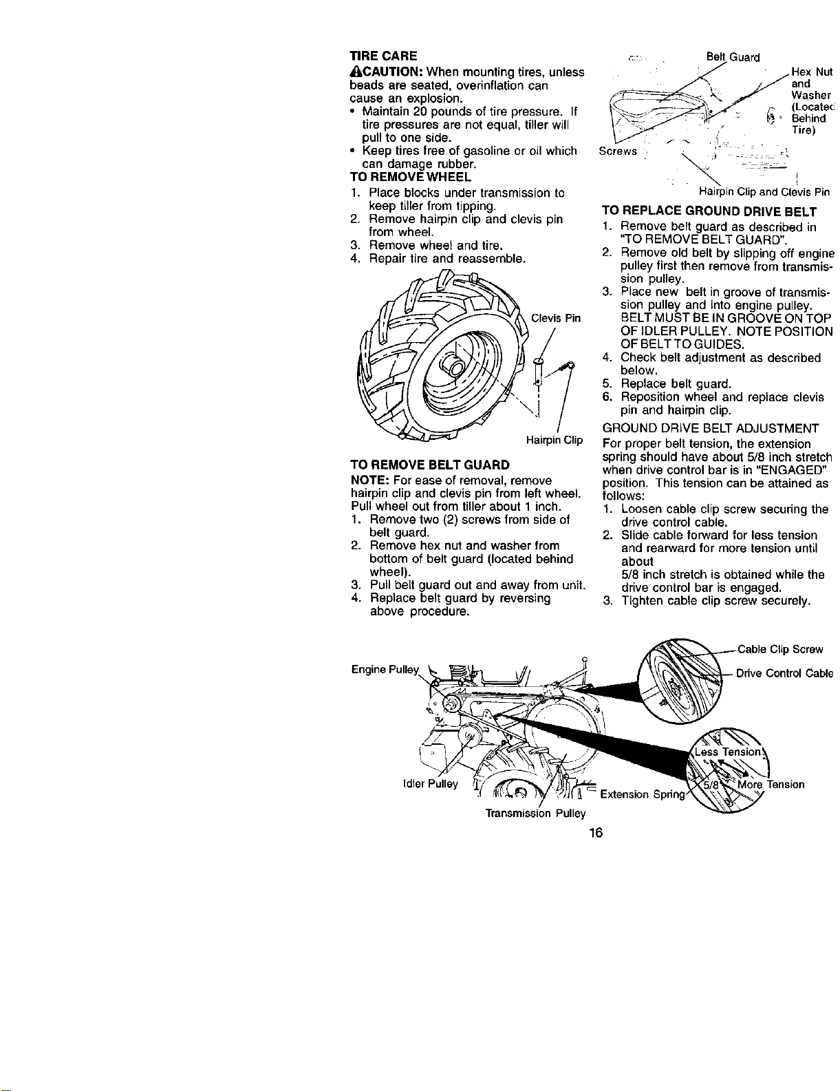
TO REMOVE WHEEL
1. Place blocks under transmission to
keep tiller from tipping.
2. Remove hairpin clip and clevis pin
from wheel.
3. Remove wheel and tire.
4. Repair tire and reassemble.
Clevis Pin
HairpinClip
TO REMOVE BELT GUARD
NOTE: For ease of removal, remove
hairpin clip and clevis pin from left wheel.
Pull wheel out from tiller about 1 inch.
1. Remove two (2) screws from side of
belt guard.
2. Remove hex nut and washer from
bottom of belt guard (located behind
wheel).
3. Pull belt guard out and away from unit.
4. Replace belt guard by reversing
above procedure,
:::: Belt Guard
Hex Nut
/_ j_,/'/and
- _ Washer
__,?_ /- (Locatec
_/_:/ _" " _ Behind
_ _: Tire)
'° :: L o',
Screws , _,_
f
HairpinClipand ClevisPin
TO REPLACE GROUND DRIVE BELT
1. Remove belt guard as described in
"TO REMOVE BELT GUARD".
2. Remove old belt by slipping off engine
pulley first then remove from transmis-
sion pulley.
3. Place new belt in groove of transmis-
sion pulley and into engine pulley.
BELT MUST BE IN GROOVE ON TOP
OF IDLER PULLEY. NOTE POSITION
OF BELT TO GUIDES.
4. Check belt adjustment as described
below.
5. Replace belt guard.
6. Reposition wheel and replace clevis
pin and hairpin clip.
GROUND DRIVE BELT ADJUSTMENT
For proper belt tension, the extension
spring should have about 5/8 inch stretch
when drive control bar is in "ENGAGED"
position. This tension can be attained as
follows:
1. Loosen cable clip screw securing the
drive control cable.
2. Slide cable forward for less tension
and rearward for more tension until
about
5/8 inch stretch is obtained while the
drive control bar is engaged.
3. Tighten cable clip screw securely.
Screw
e
Idler Pulley
TransmissionPulley
16
;pdng
More Tension
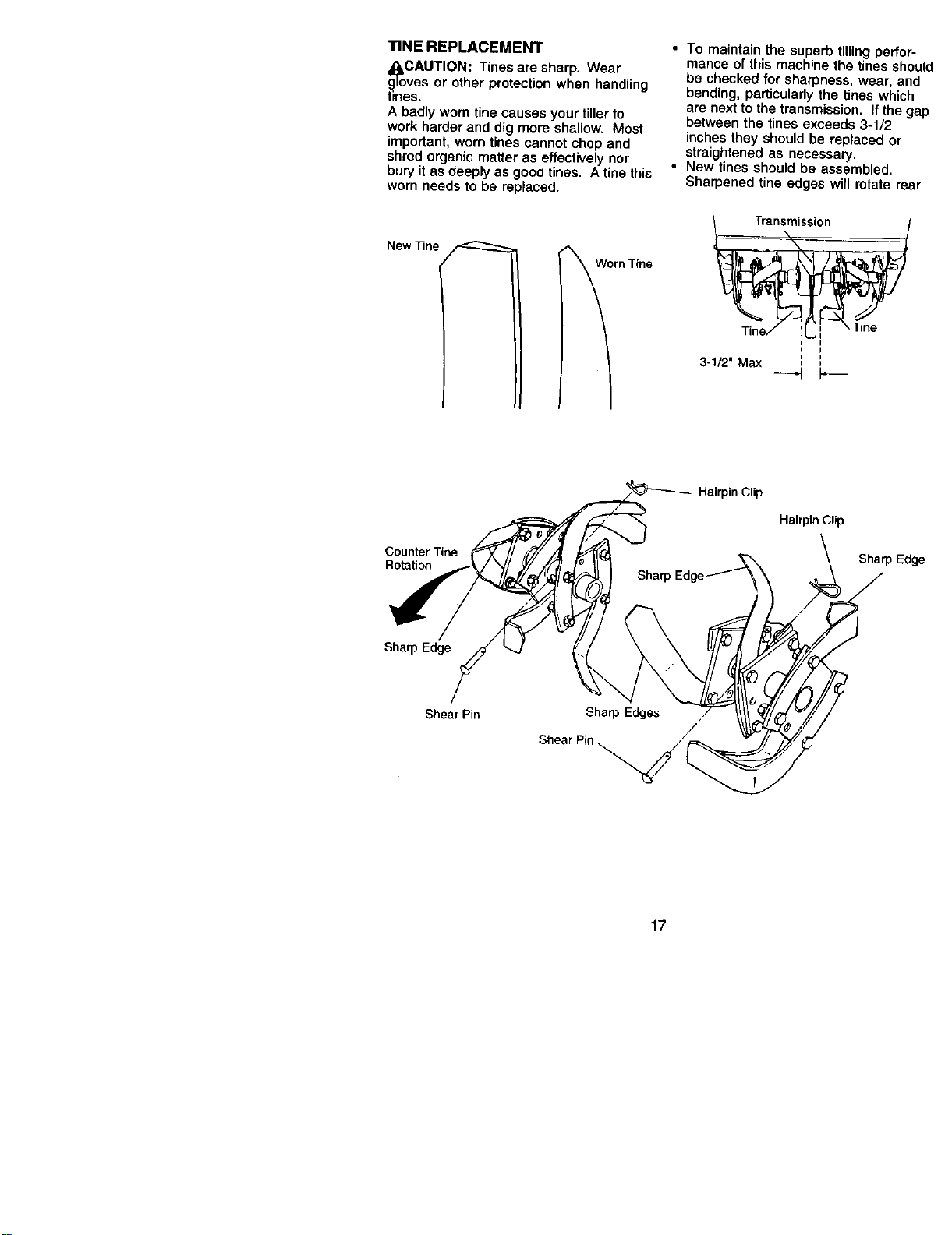
TINE REPLACEMENT
_I=CAUT|ON: Tines are sharp. Wear
gloves or other protection when handling
tines.
A badly worn tine causes your tiller to
work harder and dig more shallow. Most
important, worn tines cannot chop and
shred organic matter as effectively nor
bury it as deeply as good tines. A tine this
worn needs 1o be replaced.
New Tine
• To maintain the superb tilling perf¢
mance of this machine the tines st_
be checked for sharpness, wear, a
bending, particularly the tines whi¢
are next to the transmission. If the
between the tines exceeds 3-1/2
inches they should be replaced or
straightened as necessary.
• New tines should be assembled.
Sharpened tine edges will rotate r_.
Ti.e/ i[ i rine
I I
I
Counter Tine
Rotation
Hairpin Clip
Hairpin Clip
Sharp E
Sharp Edge
Shear Pin
Shear Pin ._
17
ENGINE
Maintenance, repair, or replacement of
the emission control devices and sys-
tems, which are being done at the
customers expense, may be performed
by any non-road engine repair establish-
ment or individual. Warranty repairs must
be performed by an authorized engine
manufacturer's service outlet.
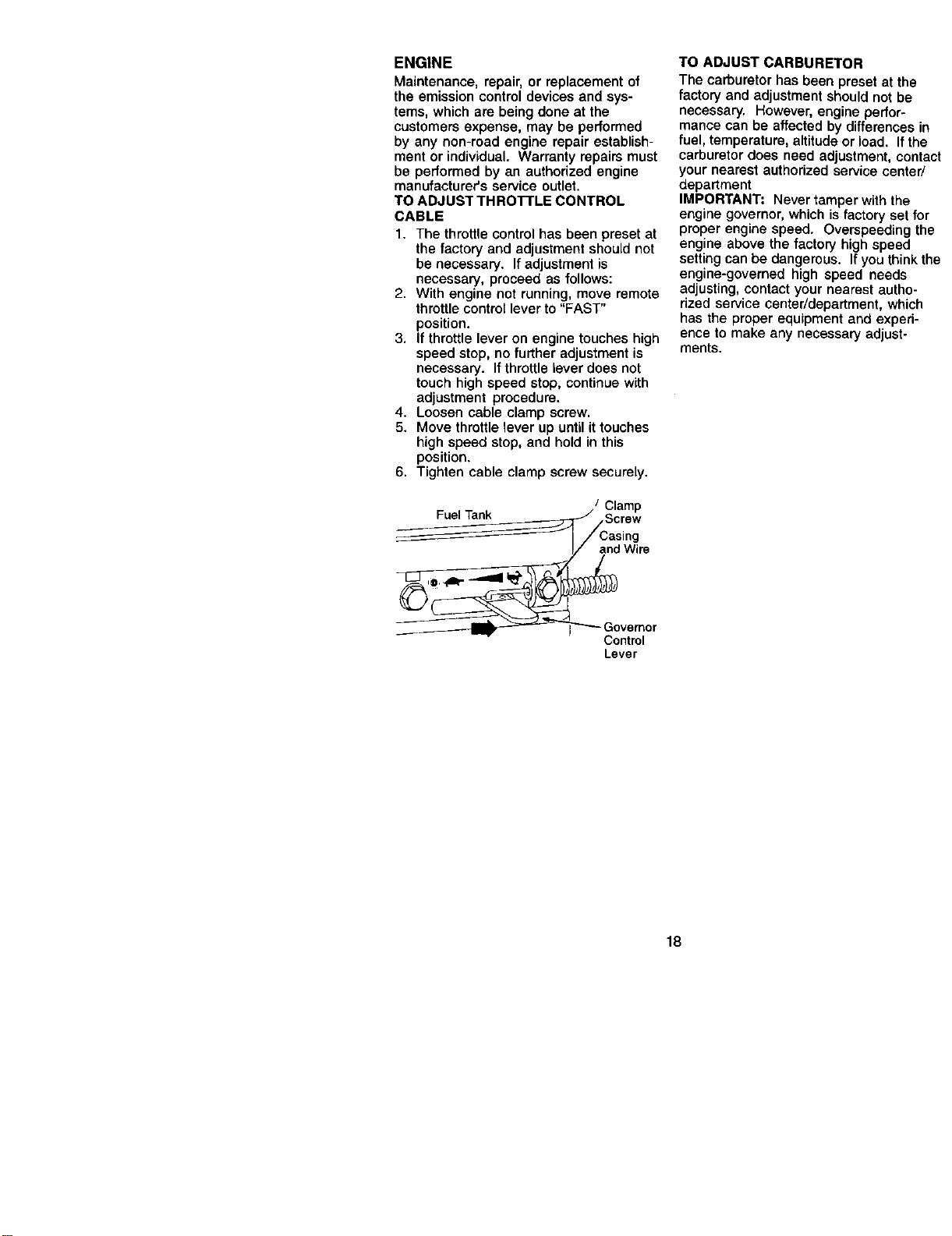
TO ADJUST THROTTLE CONTROL
CABLE
1. The throttle control has been preset at
the factory and adjustment should not
be necessary. If adjustment is
necessary, proceed as follows:
2. With engine not running, move remote
throttle control lever to "FAST"
position.
3. If throttle lever on engine touches high
speed stop, no further adjustment is
necessary. If throttle lever does not
touch high speed stop, continue with
adjustment procedure.
4. Loosen cable clamp screw.
5. Move throttle lever up until it touches
high speed stop, and hold in this
position.
6. Tighten cable clamp screw securely.
/ Clamp
__ Screw
I/ andWire
_Govemor
Control
Lever
TO ADJUST CARBURETOR
The carburetor has been preset at the
factory and adjustment should not be
necessary. However, engine perfor-
mance can be affected by differences in
fuel, temperature, altitude or load. If the
carburetor does need adjustment, contact
your nearest authorized service center/
department
IMPORTANT: Never tamper with the
engine governor, which is factory set for
proper engine speed. Overspeeding the
engine above the factory high speed
setting can be dangerous. If you think the
engine-governed high speed needs
adjusting, contact your nearest autho-
rized service center/department, which
has the proper equipment and experi-
ence to make any necessary adjust-
ments.
18
Immediately prepare your tiller for storage
at the end of the season or if the unit will
not be used for 30 clays or more.
_CAUTION: Never store the tiller with
gasoline in the tank inside a building
where fumes may reach an open flame or
spark. Allow the engine to cool before
storing in any enclosure.
TILLER
1. Clean entire tiller (See "CLEANING" in
the Maintenance section of this
manual).
2. Inspect and replace belts, if necessary
(See belt replacement instructions in
the Service and Adjustments section
of this manual).
3. Lubricate as shown in the Mainte-
nance section of this manual.
4. Be sure that all nuts, bolts and screws
are securely fastened. Inspect moving
parts for damage, breakage and wear.
Replace if necessary.
5. Touch up all rusted or chipped paint
surfaces; sand lightly before painting.
ENGINE
FUEL SYSTEM
IMPORTANT: It is important to prevent
gum deposits from forming in essential
fuel system parts such as the carburetor,
fuel filter, fuel hose, or tank during
storage, also, experience indicates that
alcohol blended fuels (called gasohol or
using ethanol or methanol) can attract
moisture which leads to separation and
formation of acids during storage. Acidic
gas can damage the fuel system of an
engine while in storage.
1. Drain the fuel tank.
2. Start the engine and let it run until the
fuel lines and carburetor are empty.
• Never use engine or carburetor cleaner
products in the fuel tank or permanent
damage may occur.
• Use fresh fuel next season.
NOTE: Fuel stabilizer is an acceptable
alternative in minimizing the formation of
fuel gum deposits during storage. Add
stabilizer to gasoline in fuel tank or
storage container. Always follow the mix
ratio found on stabilizer container. Run
engine at least 10 minutes after adding
stabilizer to allow the stabilizer to reach
the carburetor. Do not drain the gas tank
and carburetor if using fuel stabilizer.
ENGINE OIL
Drain oil (with engine warm) and replace
with clean oil. (See "ENGINE" in the
Maintenance section of this manual).
CYLINDER
1. Remove spark plug.
2. Pour I ounce (29 ml) of oil through
spark plug hole into cylinder.
3. Pull starter handle slowly several
times to distribute oil
4. Replace with new spark plug.
OTHER
• Do not store gasoline from one season
to another.
• Replace your gasoline can if your can
starts to rust. Rust and/or dirtin your
gasoline will cause problems.
• If possible, store your unit indoors and
cover it to give protection from dust and
dirt.
• Cover your unit with a suitable protec-
tive cover that does not retain moisture.
Do not use plastic. Plastic cannot
breathe which allows condensation to
form and wilt cause your unit to rust.
IMPORTANT: Never cover tiller while
engine and exhaust areas are still warm.
19
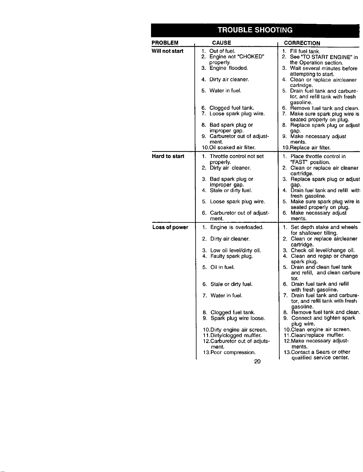
PROBLEM CAUSE CORRECTION
Will not start
Hard to start
Loss of power
1. Out of fuel.
2. Engine not "CHOKED"
properly.
3. Engine flooded.
4. Dirty air cleaner.
5. Water in fuel.
6. Clogged fuel tank.
7. Loose spark plug wire.
8. Bad spark plug or
improper gap.
9. Carburetor out of adjust-
ment.
10.Oil soaked air filter.
1. Throttle control not set
properly.
2. Dirty air cleaner.
3. Bad spark plug or
improper gap.
4. Stale ordirty fuel.
5. Loose spark plug wire.
6. Carburetor out of adjust-
ment.
1. Engine is overloaded.
2. Dirty air cleaner.
3. Low oil level/dirty oil.
4. Faulty spark plug.
5. Oil in fuel.
6. Stale or dirty fuel.
7. Water in fuel.
8. Clogged fuel tank.
9. Spark plug wire loose.
10.Dirty engine air screen.
11.Dirty/clogged muffler.
12.Carburetor out of adjuts-
ment.
13.Poor compression.
20
1. Fill fuel tank.
2. See'TO START ENGINE" in
the Operation section.
3. Wait several minutes before
attempting to start.
4. Clean or replace aircleaner
cartridge.
5. Drain fuel tank and carbure-
tor, and refill tank with fresh
gasoline.
6. Remove fuel tank and clean.
7. Make sure spark plug wire is
seated properly on plug.
8. Replace spark plug or adjust
gap.
9. Make necessary adjust
merits.
10.Replace air filter.
1. Place throttle control in
"FAST" position.
2. Clean or replace air cleaner
cartridge.
3. Replace spark plug or adjust
gap.
4. Drain fuel tank and refill with
fresh gasoline.
5. Make sure spark plug wire is
seated properly on plug.
6. Make necessary adjust
ments.
1. Set depth stake and wheels
for shallower tilling.
2. Clean or replace aircleaner
cartridge.
3. Check oil level/change oil.
4. Clean and regap or change
spark plug.
5. Drain and clean fuel tank
and refill, and clean carbure
tor.
6. Drain fuel tank and refill
with fresh gasoline.
7. Drain fuel tank and carbure-
tor, and refill tank with fresh
gasoline.
8. Remove fuel tank and clean.
9. Connect and tighten spark
plug wire.
10.Clean engine air screen.
11,Clean/replace muffler.
12.Make necessary adjust-
ments.
13.Contact a Sears or other
qualified service center.
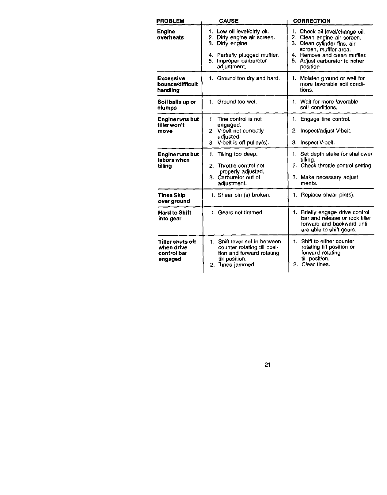
PROBLEM CAUSE CORRECTION
Engine 1. Low oil level/didy oil. 1. Check oil level/change oil.
overheats 2. Dirty engine air screen. 2. Clean engine air screen.
3. Dirty engine. 3. Clean cylinder fins, air
screen, muffler area.
4. Partially plugged muffler, 4. Remove and clean muffler.
5. Improper carburetor 5. Adjust carburetor to richer
adjustment, position.
Excessive 1. Ground too dry and hard. 1. Moisten ground or wait for
bounce/difficult more favorable soil condi-
handling lions.
Soil balls up or 1. Ground too wet, 1. Wait for more favorable
clumps soil conditions.
I
Engineruns but 1. Tine control is not 1. Engage tine control.
tillerwon't engaged.
move 2. V-belt not correctly 2. Inspect/adjust V-belt.
adjusted.
3. V-belt is off pulley(s). 3. Inspect V-belt.
Engine runs but 1, Tilling too deep, t. Set depth stake for shallower
labors when tilling.
tilling 2. Throttle control not 2. Check throttle control setting.
properly adjusted.
3. Carburetor out of 3. Make necessary adjust
adjustment, ments.
Tines Skip 1. Shear pin (s) broken. 1. Replace shear pin(s).
over ground
Hard to Shift 1. Gears not timmed, 1. Briefly engage drive control
into gear bar and release or rock tiller
forward and backward until
are able to shift gears.
Tiller shuts off
when drive
control bar
engaged
1. Shift lever set in between
counter rotating till posi-
tion and forward rotating
till position.
2. Tines jammed.
1. Shift to either counter
rotating till position or
forward rotating
till position.
2. Clear tines.
21
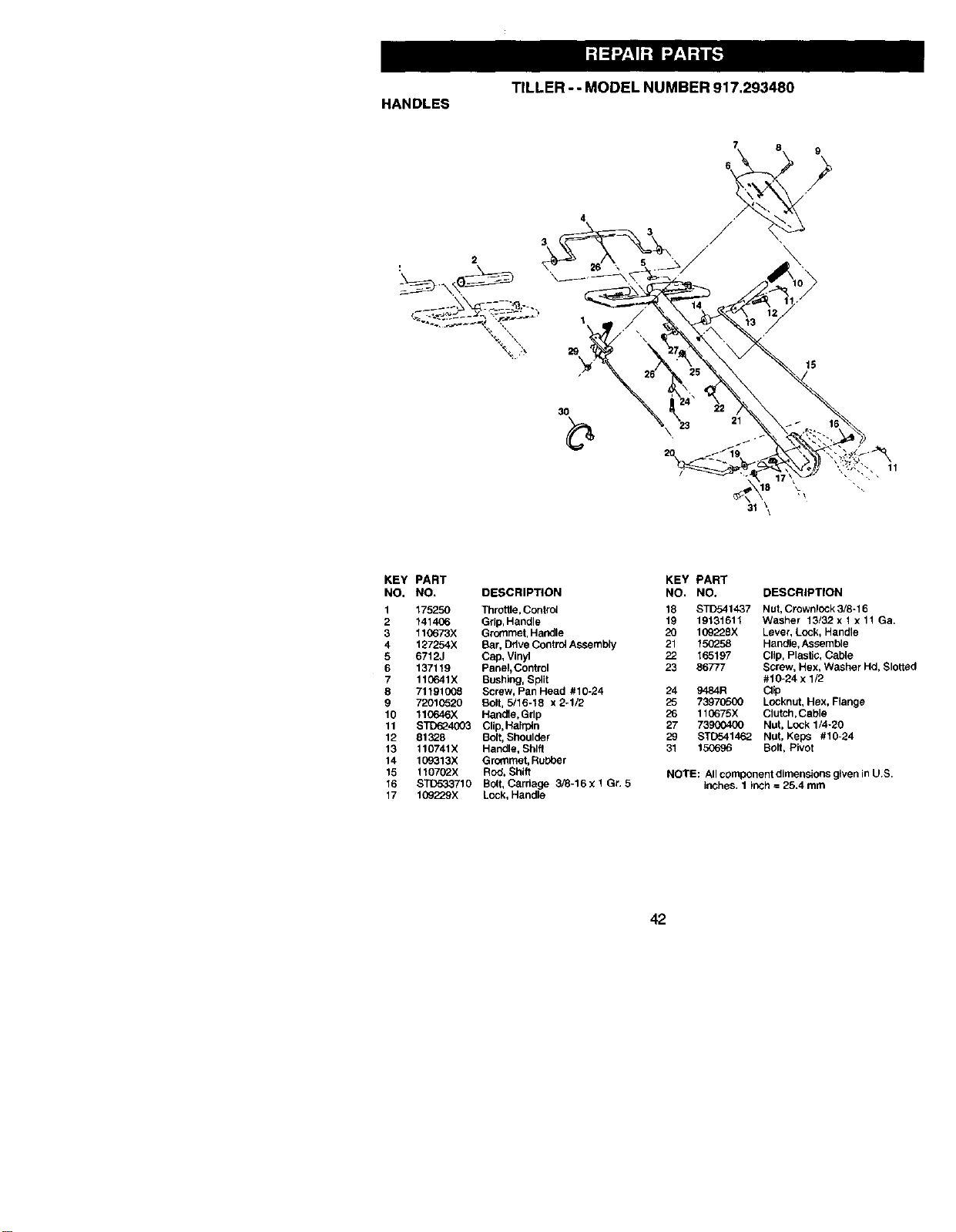
TILLER--MODELNUMBER917,293480
HANDLES
2
7 8 9
4
3O
31 \\
KEY PART
NO, NO, DESCRIPTION
1 175250 Throttle, Control
2 141406 Gdp, Haodle
3 110673X Grommet, Handle
4 127254X Bar, Drive Control Assembly
6 6712J Cap, Vinyl
6 137119 Panel,Control
7 110641X Bushing, Split
8 71191008 Screw, Pan Head #10-24
9 7201(_520 Bolt, 5/16o18 x 2-1/2
10 110646X Handle,Grip
11 BTD624003 Clip,Hairpin
12 81328 Bolt, Shoulder
13 110741X Handle, Shift
14 109313X Grommet, Rubber
15 110702X ROd, Shift
16 STO533710 Bolt, Carriage 3/8-16 X 1 Gr. 5
17 109_X Lock, Handle
KEY PART
NO. NO. DESCRIPTION
18 STD541437 Nut, Crownlock 3/8-16
19 19131611 Washer 13/32 x 1 x 11 Ga.
20 109228X Lever, Lock, Handle
21 150258 Handle, Assemble
22 165197 Clip, Plastic, Cable
23 86777 Screw, Hex, Washer Hd, Slotted
#10-24 x 1/2
24 9484R Cl_p
25 73970500 Locknut, Hex, Flange
26 110675X Clutch,Cable
27 73900400 Nut, Lock 1/4-20
29 STD541462 Hut, Kaps #10-24
31 150696 Bolt, Pivot
NOTE: All component dimensions given in U,B.
inches. 1 inch = 25.4 mm
42
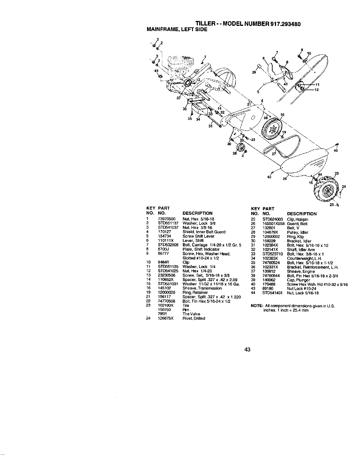
TILLER-- MODEL NUMBER 917.293480
MAINFRAME, LEFTSIDE
J2
3
65
37
\
\
36
35 3
16
31
30
28
5
23
4O
KEY PART
NO. NO.
1 73970500
2 STD551137
3 STD541037
4 170127
5 154734
6 110111X
7 STD532505
8 8700J
9 86777
10 9484R
11 STD551125
12 STD541(_5
13 23230506
14 t10652X
15 STD551D31
16 14510_
19 12000028
21 156117
22 74770508
23 102190X
150750
795R
24 126875X
DESCRIPTION
Nut, Hex 5/16-18
Washer, Lock 3/8
Nut, Hex 3/8-16
Shield, Inner Belt Guard
Screw Shi6 Lever
Lever, Shift
Bolt, Carriage 1/4-20 x 1/2 Gr. 5
Plate, Shift Indicator
Screw, Hex, Washer Head,
Slotted #10-24 x 1/2
C_ip
Washer, Lock 1/4
Nut, Hex 1/4-20
Screw, Set, 5/16-18 x 3/8
Spacer, Split .327 x .42 x 2.09
Washer 11/32 x 11/16 x 16 Ga.
Sheave, Transmission
Ring, Retainer
Spacer, Split .327 x ,42 x 1.220
Bolt, Fin Hex 5/16-24 x 1/2
_re
Rim
Tire Valve
Rivet, Odlled
25
KEY PART
NO, NO. DESCRIPTION
25 STD624003 Clip, Hairpin
26 165501X558 Guard, Belt
27 132801 Belt, V
28 104679)( Pulley, Idler
29 12000032 Ring, Kllp
30 159229 Bracket, Idler
31 102384X Bolt, Hex 5/16-16 x 12
32 10_t41X Shaft, Idler Arm
33 STD523710 Bolt, Hex 3/6-16xl
34 102383X Counterweight, L.H.
35 7476(3524 Bolt, Hex 5/16-16 x 1-1/2
36 102331x Bracket, Reinforcement, L.H.
87 130812 Sheave, Engine
38 74760544 Bolt, Fin Hex 5/16-18 x 2-3/4
39 140662 Cap, Plunger
40 170488 Screw Hex Wsh. Hd #1 0-32 x 9/16
43 69180 Nut Lock #1 0-24
44 STD541431 Nut, Lock 5/16-18
NOTE: All component dimensions given in U.S.
inches. 1 inch = 25.4 mm
43
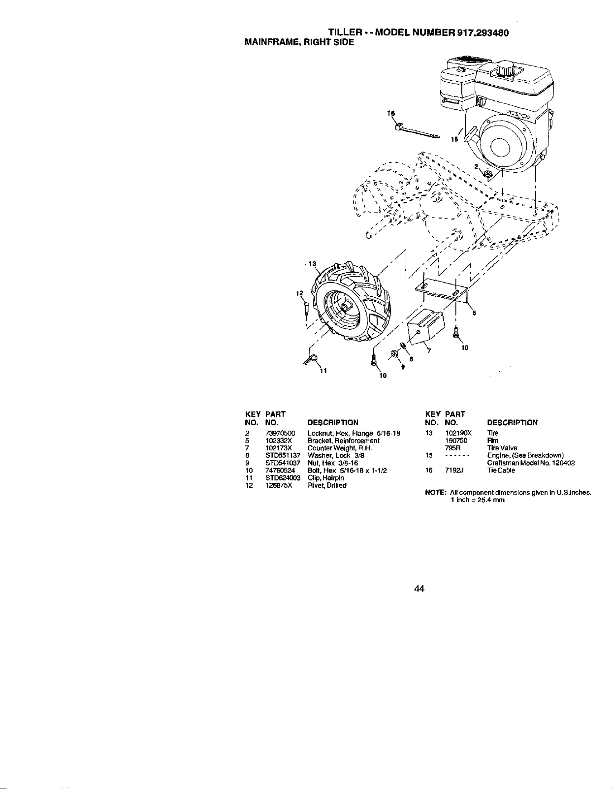
TILLER- - MODEL NUMBER 917.293480
MAINFRAME, RIGHT SIDE
16
13
11
//
"t
8
9
10
KEY PART
NO. NO. DESCRIPTION
2 73970500 Locknut, Hex, Flange 5116-18
5 102332X Bracket, Reinforcement
7 102173X Counter Weight, R.H,
8 STD551137 Washer, Lock 3/8
9 STC5410G7 Nut, Hex 3/8-16
10 74760524 Bolt, Hex 5/16-18 x 1-1/2
11 STD624(X)3 Clip, Hairpin
12 126875X Rivet, Drilled
KEY PART
NO, NO. DESCRIPTION
13 l(_lgOX Tire
150750 Rim
795R Tire Valve
15 ...... Engine, (See Breakdown)
Craftsman Model No. 120402
16 7192J _eCab_e
NOTE: All component dimensions given in U.S,inches.
1 inch = 25.4 mm
44
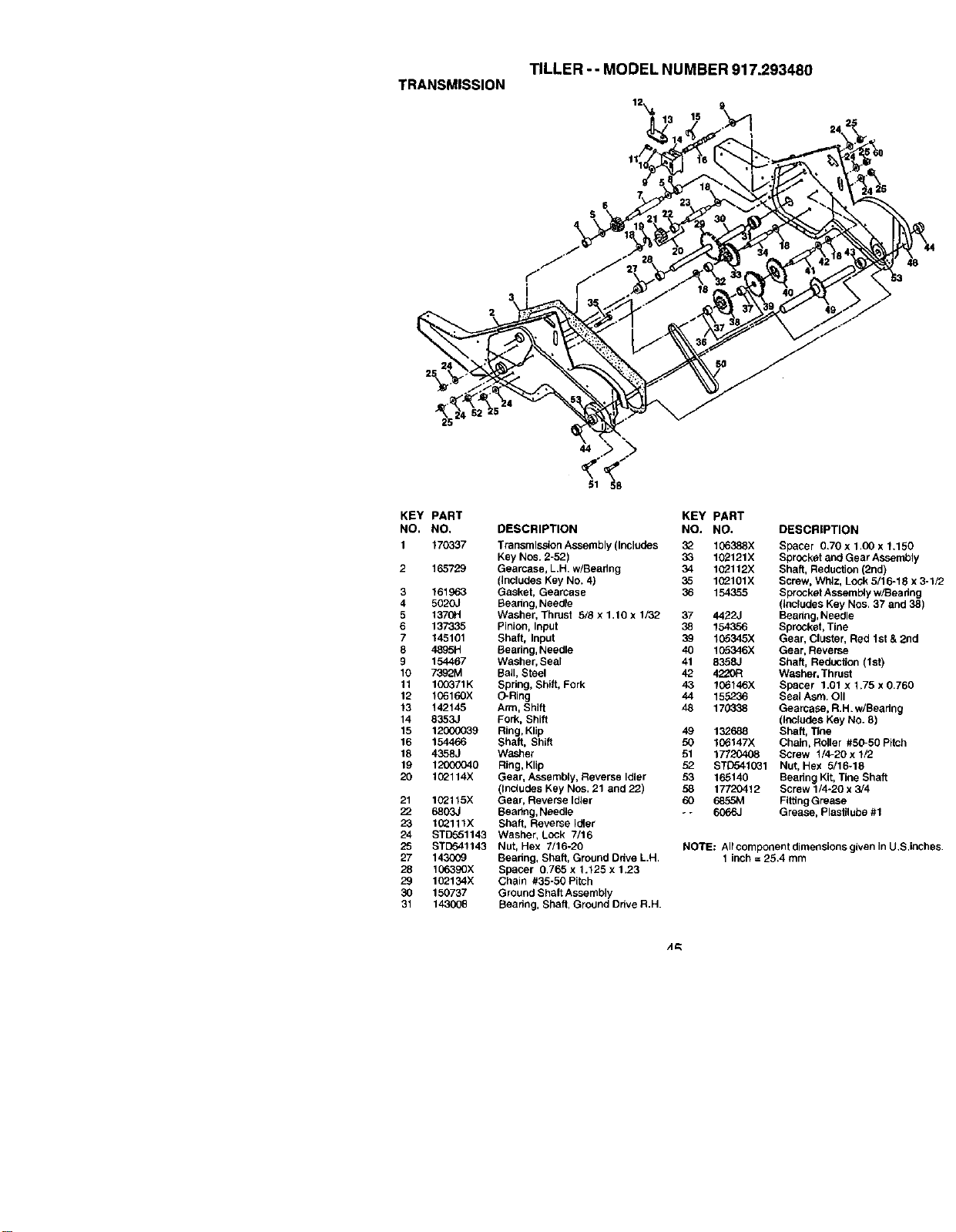
TILLER-- MODEL NUMBER 917.293480
TRANSMISSION
2
KEY PART KEY PART
NO. NO. DESCRIPTION NO. NO. DESCRIPTION
1 170337 Transmission Assembly (Includes 32 106388X Spacer 0.70 x 1,00 x 1.150
Key Nos. 2-52) 33 102121X Sprocket and Gear Assembly
2 165729 Gearcase, L.H. w/Beadng 34 102112X Shaft, Reduction (2nd)
(Includes Key No. 4) 35 1G2101X Screw, Whiz, Lock 5/16-18 x 3-1/2
3 161963 Gasket, Gearcase 36 154355 Sprocket Assembly w/Beadng
4 5620.1 Beadng, Needle (includes Key Nos. 37 and 38)
5 1370H Washer, Thrust 5/8 x 1.10 x 1/32 37 4422J Beadng, Needle
6 137335 Pinion, Input 38 154356 Sprocket, Tine
7 145101 Shaft, Input 39 105345X Gear, Cluster, Red 1st & 2nd
8 4895H Beadng, Needle 40 105346X Gear, Reverse
9 154467 Washer, Seal 41 8358J Shaft, ReducUon (1st)
10 7392M BaH, Steel 42 4220R Washer, Thrust
11 10_371K Spdng, Shift, Fork 43 106146X Spacer 1.01 x 1.75 x 0.760
12 106160X O-Ring 44 155236 Seal Asm. OII
13 142145 Arm, Shift 48 170338 Gearcase, R.H. w/Bearing
14 835;33 Fork, Shift (Includes Key NO. 8)
15 12000039 Ring, KlJp 49 132688 Shaft, TIne
16 154466 Shaft, Shift 50 106147X Chain, Roller #56-50 Pitch
18 4358J Washer 51 17720408 Screw 1/4-20 x 1/2
19 12000040 Ring, Klip 52 STD541031 Nut, Hex 5/16-18
20 102114X Gear, Assembly, Reverse Idler 53 165140 Beadng Kit, Tine Shaft
(Includes Key Nos. 21 and 22) 58 17720412 Screw 1/4-20 x 3/4
21 102115X Gear, Reverse Idler 60 6855M Fitting Grease
22 6803J Bearing, Needle - - 6066J Grease, Plastiluba #1
23 1(3_111X Shaft, Reverse Idler
24 STD551143 Washer, Lock 7/16
25 STD541143 Nut, Hex 7/16-20 NOTE; AlfcomponentdimensionsglvenlnU.S.inches.
27 143(X_ Beadng, Shaft, Ground Ddve L.H, 1 inch = 25.4 mm
28 106390X Spacer 0.765 x 1.125 x 1.23
29 102134X Chain #35-50 Pitch
30 150737 Ground Shaft Assembly
31 143008 Beadng, Shaft, Ground Drive R.H.

TILLER -- MODEL NUMBER 917.293480
TINESHIELD
KEY PART KEY PART
NO. NO. DESCRIPTION NO. NO, DESCRIPTION
1 73900500 Nut, Lock Hex Flange 5/16-18 UNC 19 102701X Grip
2 161415X558 Shield, Side, Outer L.H. 20 STD541037 Nut, Hex 3/8-16
3 6393J Pin, Stake. Depth 21 102156X Stake, Depth
4 120(X_36 Ring, Klip 22 74930632 Bolt, Hex 3/8-16 x 2
5 STD533107 Bolt, Carriage 5/16-18 x 3/4 Gr 5 23 4440J Hinge
6 8394J Spdng 24 STD532505 Bolt, Cardage 1/4-20 x 1/2
7 8392J Bracket, Latch 25 6712J Cap, Vinyl
8 109230X Spring, Depth Stake 26 169227X Pad, Idler
9 1023,?.6X558 Shield,Tine 27 102695X558 Shield, Leveling
10 $11_._._._._._._._._3110Bolt, Dardage 5/16-18 x 1 Gr. 5 28 120588X Pin, Hinge
11 STD541031 Nut, Hex 5/16-16 29 104085X556 Shield, Side
12 STD551131 Washer, Lock 5/16 3_ 73220400 Nut, Fin, Hexl/4-20UNC
13 STD533112 Bolt, Cardage 5/16-18 x 1-1/4 33 STD551125 Washer Lock Hvy Helical 1/4
14 124343 Bracket, Shield Tine
15 1614t4X558 Shield, Side, Outer R.H.
16 73900400 Nut, Flange lock 1/4-20 NOTE: All component dimensions given In U.S. inches
17 162175 Nut, Wing Forged 5/16-18 1 inch = 25.4 mm
18 STD532512 Bolt, Dardage 1/4-20 x 1-1/4 Gr. 5
46
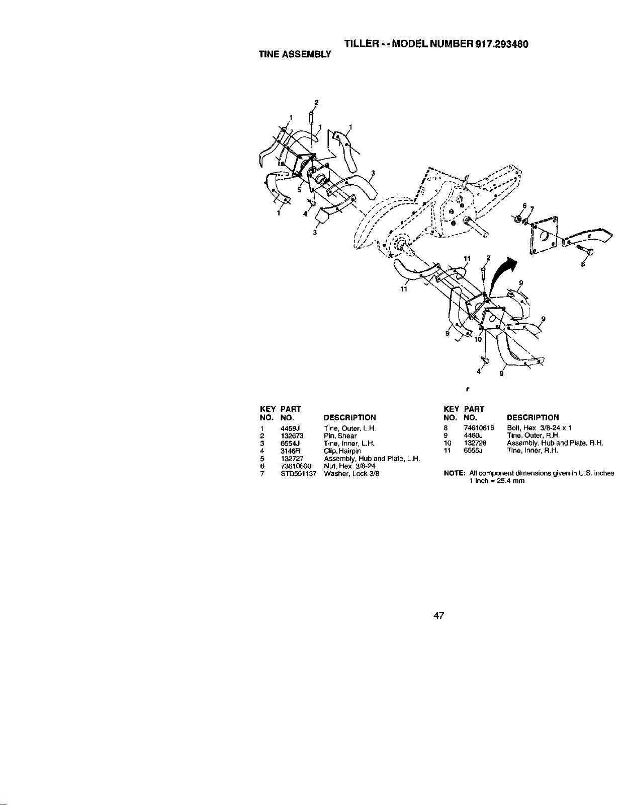
TILLER -* MODEL NUMBER 917.293480
TINE ASSEMBLY
2
1
1
4
3
11
p •
9
KEY PART
NO. NO, DESCRIPTION
1 4459J Tine, Outer, L.H.
2 132673 Pin, Shear
3 6554J Tine, Inner, LH.
4 3146R Clip, Hairpin
5 132727 ASSembly, Hub and Plate, L.H.
6 73610600 Nut, Hex 3/8-24
7 STD551137 Washer, Lock3/8
KEY PART
NO, NO. DESCRIPTION
8 74610616 Bolt, Hex 3/8-24 x 1
g 4460J Tine, Outer, R.H.
10 132728 Assembly, Hub and Plate, R.H.
11 6555J Tlne, Inner, R.H.
NOTE: All component dimensions given in U.S. inches
1 inch = 25.4 mm
47
TILLER--MODELNUMBER917.293480
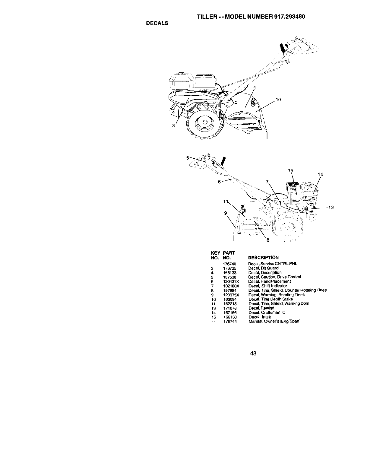
DECALS
15
KEY PART
NO. NO. DESCRIPTION
1 176740 Decal, Sewice CNTRL PNL
3 176735 Decal, BitGuard
4 166133 Decal, Description
5 137538 Decal, Caution, Drive Contro_
6 120431X Decal, Hand Placement
7 102180X Decal, Shilt Indicator
8 157984 Decal, Tine, Shield, Counter Rotating Tines
9 t20075X Decal, Waming, Rotating Tines
10 t 63094 Decal, Tine Depth Stake
11 162215 Decal, Tine, Shield, Warning Dom
13 171078 Decal, Rewind
14 167156 Decal Craftsman IC
15 166138 Decal, Intak
- - 176744 Manual, Owner's (Eng/Span)
48
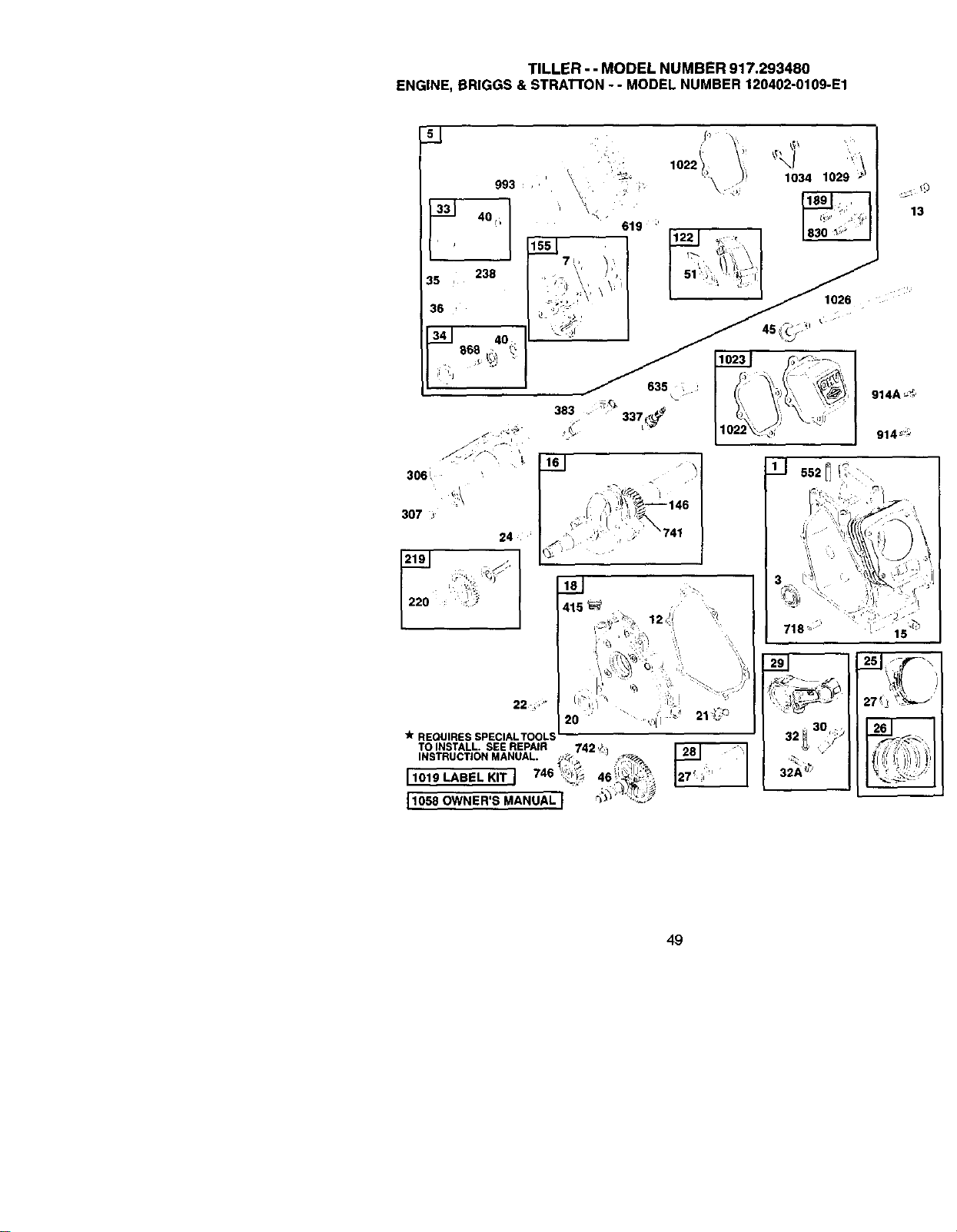
TILLER- - MODEL NUMBER 917.293480
ENGINE, BRIGGS & STRATrON - - MODEL NUMBER 120402-0109-E1
24 J
22_290 • d:
220 :
415
I,
20
REQUIRESSPECIALTOOL_
TOINSTALL. SEEREPAIR _ 742 ,,_ _
INSTRUCTIONMANUAL. ,.:_ " L _
11050 OWNER'S MANUAL I _-_i'"_C;"
27_ '_--_'
30
32_ _;J
49
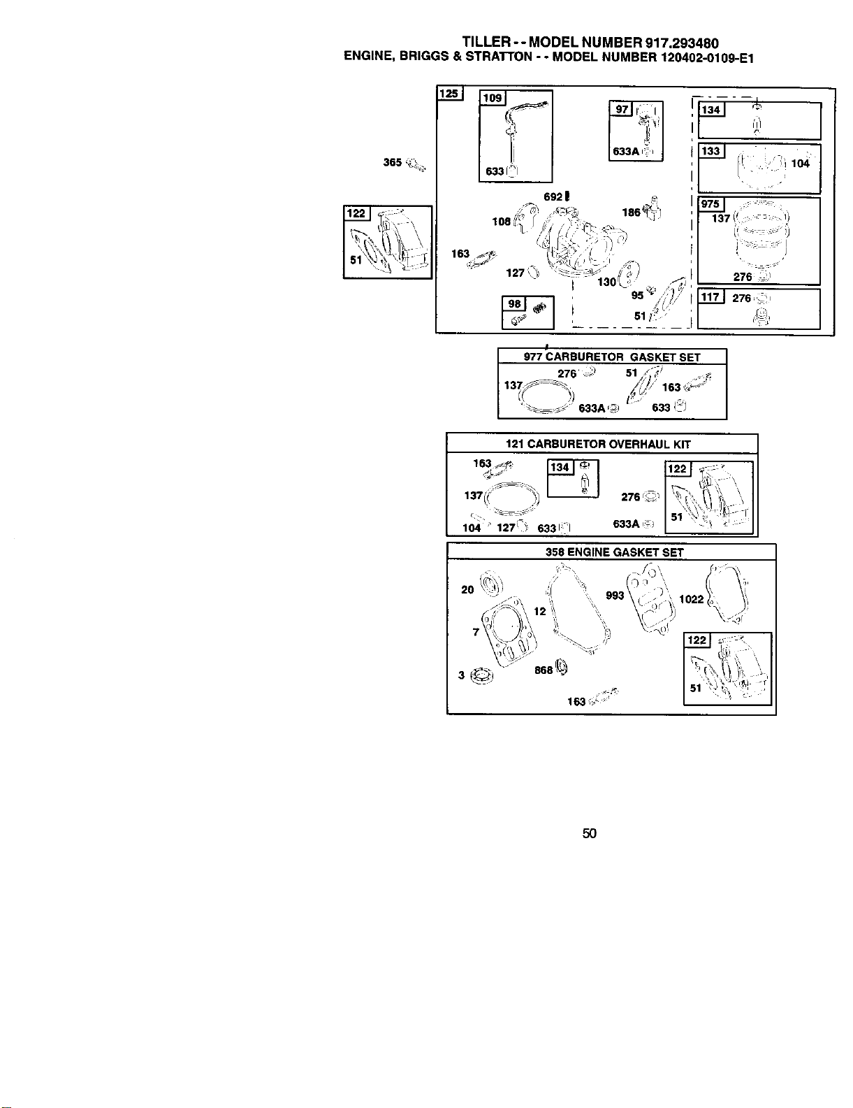
TILLER-- MODEL NUMBER 917.293480
ENGINE, BRIGGS & STRAI"TON- - MODEL NUMBER 120402-0109-E1
365 _i ],
I
I 977 CARBURETOR GASKET SET
276 _) 51 s_; i ._-_
'_s _:': 633A_/ /_:'_"633 I'-i
353 ENGINE GASKET SET
3 i
50
TILLER--MODELNUMBER917.293480
ENGINE,BRIGGS&STRATTON-- MODEL NUMBER 120402-0109-E1
, _ +_ 66_ +/" 267 ,_,_
i(; 5o5'_ _,
281 ,_
,_+I"(!-_I
11 ,_-
445 _
51
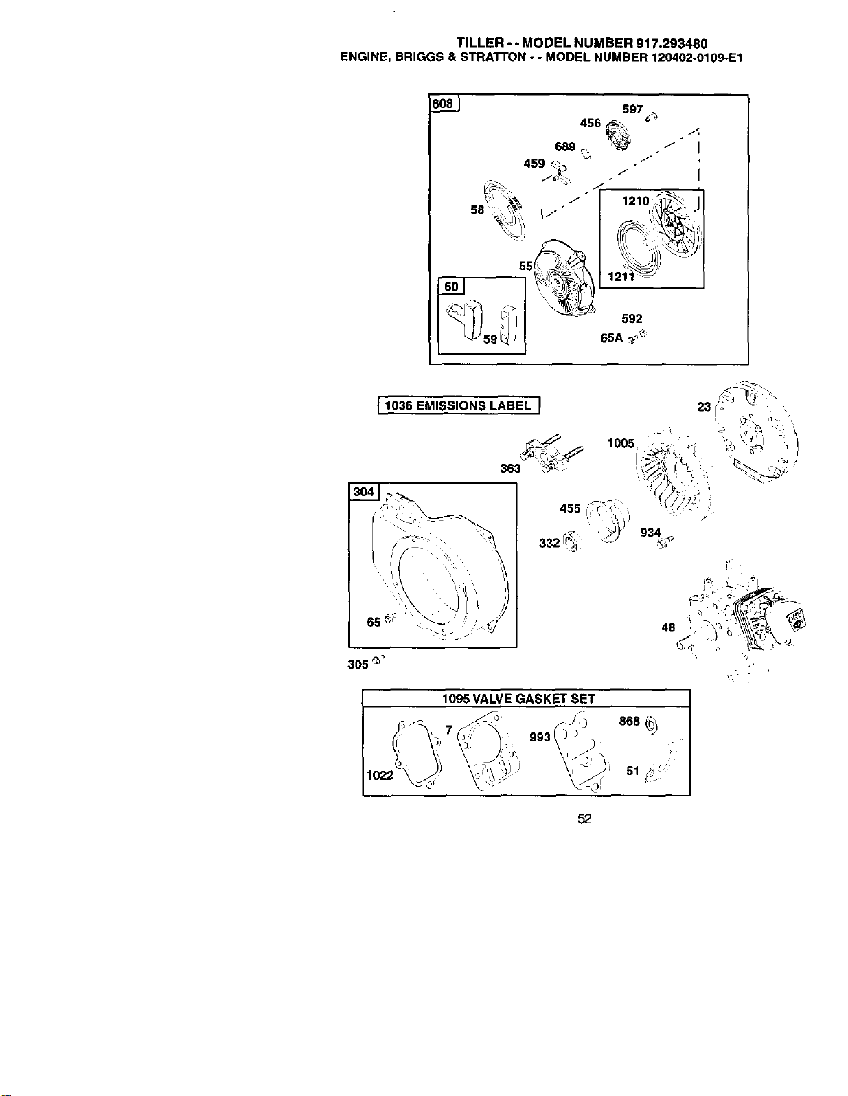
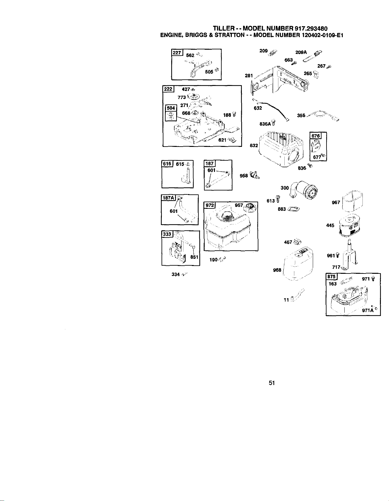
TILLER- - MODEL NUMBER 917.293480
ENGINE, BRIGGS & STRATTON- - MODEL NUMBER 120402-0109-E1
597_
456 _ "
689 ,_. _:' .
.J
.J
1210f _" i
56 • i!1 ' i
_ 1211 "_
59 65A _;
[ 1036 EMISSIONS LABEL ]
305 _
1005
1095 VALVEGASKET SET
52
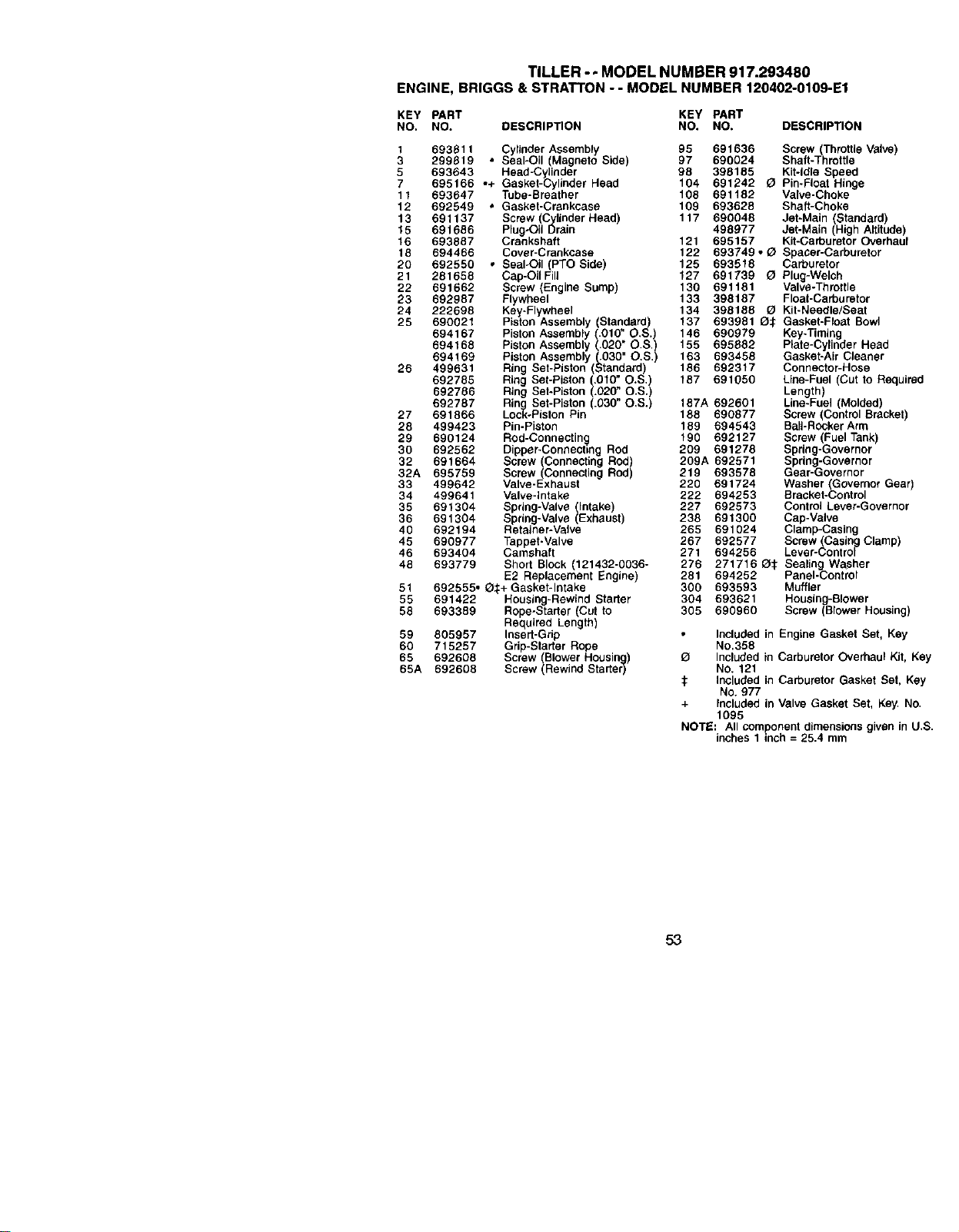
TILLER - - MODEL NUMBER 917.293480
ENGINE, BRIGGS & STRATTON - - MODEL NUMBER 120402-0109-E1
KEY PART KEY PART
NO. NO. DESCRIPTION NO. NO. DESCRIPTION
1 69381 t Cylinder Assembly 95 691636 Screw (Throttle Valve)
3 299819 * Seal-Oil (Magneto Side) 97 690024 Shaft-Throttle
5 693643 + Head-Cylinder 98 398185 Kit-idle Speed
7 695166 ° Gasket-Cylinder Head 104 691242 _ Pin-Float Hinge
11 693647 Tube-Breather 105 691182 Valve-Choke
12 692549 • Gasket-Crankcase 109 693628 Shaft-Choke
13 691137 Screw (Cylinder Head 117 690048 JeEMain (Standard)
15 691686 Plug-Oil Drain 498977 Jet-Main (High Altitude)
16 693887 Crankshaft 121 695157 Kit-Carburetor Overhaul
18 694466 Cover-Crankcase 122 693749 • (_ Spacer-Carburetor
20 692550 • Seal-Oil (PTO Side) 125 693518 Carburetor
21 281658 Cap-OilFill 127 691739 O Plug-Welch
22 691662 Screw (Engine Sump) 130 691181 Valve-Throttle
23 692987 Flywheel 133 398187 Float-Carburetor
24 222698 Key*Flywheel 134 398188 _ Kit-Needle/Seat
25 690021 Piston Assembly (Standard) 137 693981 Q:_ Gasket-Float Bowl
694167 Piston Assembly (.010" O.S.) 145 690979 Key-Timing
694158 Piston Assembly (.020" O.S,) 155 695982 Plate-Cylinder Head
694169 Piston Assembly (.030" O,S,) 163 693458 Gasket-Air Cleaner
26 499631 Ring Set-Piston (Standard) 186 692317 Connector-Hose
692785 Ring Set-Piston (.010" O.S,) 187 691050 Line-Fuel (Cut to Required
692786 Ring Set-Piston (.020" O.S.) Length)
692787 Ring Set-Piston (.030" O,S.) 187A 692601 Line-Fuel (Molded)
27 691866 Lock-Piston Pin 185 690877 Screw (Control Bracket)
28 499423 Pin-Piston 189 694543 Bali-Rocker Arm
29 690124 Rod-Connectin,_ 190 692127 Screw (Fuel Tank)
30 692562 Dipper-Connec6ng Rod 209 691278 Spring-Governor
32 691664 Screw (Connecting Rod) 209A 692571 Spring-Governor
32A 695759 Screw (Connecting Rod) 219 693578 Gear-Governor
33 499642 Valve-Exhaust 220 691724 Washer (Governor Gear)
34 499641 Valve-intake 222 694253 Bracket-Control
35 691304 Spring-Valve (Intake) 227 692573 Control Lever-Governor
36 691304 Spring-Valve (Exhaust) 238 691300 Cap-Valve
40 692194 Retainer-Valve 265 691024 Clamp-Casing
45 690977 Tappet-Valve 267 692577 Screw (Casing Clamp)
46 693404 Camshaft 271 694256 Lever-Control
48 693779 Short Block (121432-0036- 276 271716 _li; Sealing Washer
E2 Replacement Engine) 281 694252 Panel-Control
51 692555. Q._+Gasket-Intake 300 693593 Muffler
55 691422 Housing-Rewind Starter 304 693621 Housing-Blower
58 693389 Rope-Starter (Cut to 305 690960 Screw (Blower Housing)
Required Length)
59 605957 Insert-Grip Included in Engine Gasket Set, Key
60 715257 Grip-Starter Rope No.368
65 692608 Screw (Blower Housing) Q Included in Carburetor Overhaul Kit, Key
65A 692608 Screw (Rewind Starter) NO. 121
:1: Included in Carburetor Gasket Set, Key
No. 977
+ Included in Valve Gasket Set, Key. No.
1095
NOTE: All component dimensions given in U.$.
inches 1 inch = 25.4 mm
53
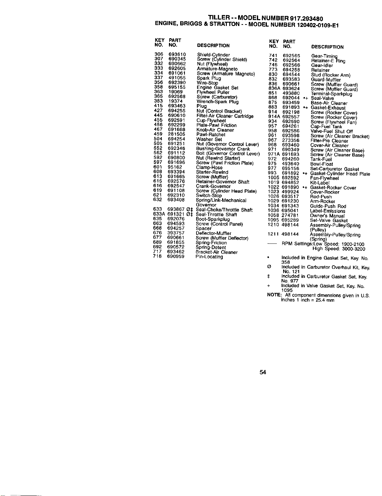
TILLER -- MODEL NUMBER 917.293480
ENGINE, BRIGGS & STRATTON - - MODEL NUMBER 120402-0109-E1
KEY PART KEY PART
NO. NO. DESCRIPTION NO. NO. DESCRIPTION
306 693610 Shie(d-Cy;leder 741 692565 Gear-Timle 9
307 690345 Screw (Cylinder Shield) 742 692564 Ratainer-ERing
332 690662 Nut (Flywheel) 746 692566 Gear-Idler
333 692605 Armature-Magneto 773 694258 Retainer
334 691061 Screw (ArmataTe Magneto) 830 694544 Stud (Rocker Arm)
337 491055 Spark Plug 832 693583 Guard-Muffler
356 692390 Wire-Stop 836 690661 Screw (Muffler Guard
358 695156 Engine Gasket Set 836A 693624 Screw Muffer Guard
363 19069 Flywheel Puller 851 493880 Terminal-Sparkplug
365 692568 Screw (Carburetor) 868 692044 o+ Seal-Valve
383 19374 Wrench-Spark Plug 875 693459 Base-Air Cleaner
415 693463 Plug 883 691893 .+ Gasket-Exhaust
427 694255 Nut (Control Bracket) 914 692198 Screw RockerCover)
445 690610 Filler-Air Cleaner Cartridge 914A 692557 Screw Rocker Cover
455 692591 Cup-Fl.ywrwheel 934 692590 Screw (Flywheel Fan)
456 692299 Pl_e-Pawl Friction 957 694261 Cap-Fuel Tank
467 691668 Knob-Air Cleaner 958 692586 Valve-Fuel Shut Off
459 281505 PawI-Ratchet 961 693598 Screw Air Cleaner Bract
504 694254 Washer Set 967 273356 Fiter-Pre Cleaner
505 691251 Nut (Go,Jemor Conlrot Lever) 968 693460 Cover-Air Cleaner
552 692346 Bushing-Governor Crank 971 690349 Screw (Air Cleaner Base
562 691112 Belt (Governor Control Lever) 971A 691699 Screw (Air Cleaner Base
592 690800 Nut (Rewind Staffer 972 694260 Tank-Fuel
597 691696 Screw (Pawi FrictionP ate) 975 493640 Bowl-Float
901 95162 Clamp-Hose 977 695156 Set-Carburetor Gasket
998 693394 Starter-Rewind 993 691892 .+ Gasket-Cylinder Head P
613 691665 Screw (Muffler) 1005 692592 Fan-Flywheel
615 692576 Retainer-Governor Shaft 1019 694852 Kit-Label
616 692547 Crank-Governor 1022 691890 .+ Gasket-Rocker Cover
619 691108 Screw (Cylinder Head Plate) 1023 499924 Cover-Rocker
521 692310 Switch-Stop 1026 693517 Rod-Push
632 693408 Spdng/Link-Mechanical 1029 691230 Arm-Rocker
Governor 1034 691349 Guide-Push Rod
633 693867 C1€ Seal-Choke/Throttle Shaft 1036 695041 Label-Emissions
633A 691321 CIr. Sea_-Throttte Shaft 1058 274781 Owner's Manual
635 692076 BooHSparkplug 1095 695289 Set-Valve Gasket
663 694593 Screw (ContrOl Panel) 1210 498144 Assembly-Pulley/Spring
668 694257 Spacer (Pulley)
676 393757 Dellector-Muffler 1211 498144 Assembly-Pulley/Spring
677 690661 Screw (Muffler Deflector) (Spring)
689 691855 Spring-Friction -- RPM Settings:Low Speed: 1900-210¢
692 690572 Spring-Detent High Speed: 3000-320(
717 693462 Bracket-Air Cleaner
718 690959 Pin-Locating Included in Engine Gasket Set, Key. r,
358
O Included in Carburetor Overhaul Kit, :_
No. 121
:_ Included in Carburetor Gasket Set, K_
No, 977
+ Included in Valve Gasket Set, Key. No
1095
NOTE: All component dimensions given in L
inches 1 inch = 25.4 mm
54

55

Get it fixed, at your home or ours!
For repair of major brand appliances in your own home...
no matter who made it, no matter who sold it!
1-800-4-MY-HOME sMAnytime,dayor night
(1-800.-469..4663)
www.sears.com
To bring in products such as vacuums,
lawn equipment and electronics for repair, call for
the location of your nearest Sears Parts & Repair Center.
1-800-488-1222 Anytime,dayor night
www.sears.com
For the replacement parts, accessories and owner's manuals
that you need to do-it-yourself,call Sears PartsDirectSi!
1-800-366-PART 6a.m.- 11 p.m. CST,
(1-800-366-7278) 7 days a week
www.sears.com/partsdirect
To purchase or inquire about a Sears Service Agreement:
1-800-827-6655
7 a.m. - 5 p.m. CST, Mort. - Sat.
Para pedlrserviclode reparaci6na domicllio,
y para ordenarplezas conentrega a domicilio:
1-888-SU-HOGAR _
(1-888-784-6427)
Au Canada pour service en fran_ais:
1-877-LE-FOYER_"
(1-877-533-6937)
0 Seam, Roebuck and CO.
® Registered Trademark / TM Trademark of Sears, Roe_Jck and Co,
TM
® M_ rq_.FJggi,_.tt_da / MarCa de Fdbrica de Sears, Roebuck and Co.
176744 Rev. 1 12.4.00 TR P_intedJn-U,_.A.