035-15857-402
Rev.
B
(0402)
ACCESSORY
KIT
INSTALLATION
INSTRUCTIONS
2SA067*
START
KITS
FOR
AIR
CONDITIONERS
AND HEAT
PUMPS
IMPORTANT
-
These
instructions
are
intended
for
the
use
of
qualified
individuals
specially
trained
and
experi-
enced
in
installation
of
this
type
of
equipment
and
related
system
components.
Installation
and service
personnel
are
required
by
some
states
to
be
licensed.
Persons
not
qualified
shall
not
install
this
equipment
or
interpret
these
instructions.
AWARNING
Improper
installation
may
damage
equipment,
can create
a
shock
hazard,
and
will
void
the
warranty.
NOTE:
The
words
“Shall”
or
“Must"
indicate
a
require-
ment
which
is
essential
to
satisfactory and
safe
product
performance.
The
words
“Should"
or
“May"
indicate
a
recom-
mendation
or
advice
which
is
not
essential
and
not
required
but
which
may
be
useful
or
help-
ful.
CONTENTS
OF
KIT
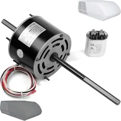
The
compressor
starting
kit
consists
of
a
potential
(starting)
relay,
screws,
capacitor
strap
and
starting
capacitor
with
wiring
leads.
Kit
may
contain
more
hard-
ware
than
necessary
for
some
models
and wires
may
be
longer
than
required.
Start
kits
for
the
various
mod-
els
are
listed
in
Table
1.
IMPORTANT
-
Do
not
mis-match
kits
or
damage
will
occur
to
the
equipment.
APPLICATION
The
compressor
in
the
outdoor
unit
has
a
PSC
(perma-
nent
split
capacitor)
motor
which
does
not
require
a
starting
relay
and
capacitor,
under
ordinary
operating
conditions.
The
omission
of
these
components
elimi-
nates
a
potential
source
of
field
problems
making
the
system
more
trouble-free.
In
order
to
take
advantage
of
these
benefits
and
trou-
ble-free
operation,
the
starting
torque,
or
load,
must
be
kept
to
a
minimum.
The
suction
and
discharge
pres-
sures
must
be
nearly
equal
before
the
compressor
will
start.
Because
of
the
lower
starting
torque
inherent
in
PSC
motors,
certain
conditions
such
as
low
voltage
and
exceptionally
high
operating
temperature,
short
ther-
mostat
cycles,
etc.
can
affect
the
starting
operation.
When
such
conditions
exist,
and
cannot
be
corrected,
it
is
recommended
that
the
field
installed
compressor
starting
kit
be
used
to
convert
the
compressor
motor
to
CSR
(capacitor,
capacitor
run)
operation.
NOTE:
All
Start
Kits
listed
in
these
instructions
are
for
use
with
outdoor
units
rated
at
208-230V/
1PH/
60HZ.
AWARNING
SHOCK
HAZARD
-
Shut
off
electrical
supply
to
outdoor
unit
at
main
disconnect.
One
side
of
the
contactor
remains
closed
at
all
times,
so
main
disconnect
must
be
opened
when
servic-
ing
electrical
components
to
prevent
electrical
shock,
which
could
result
in
personal
injury
or
death.
Unitary
Products
Group
035-15857-402
Rev.
B
(0402)
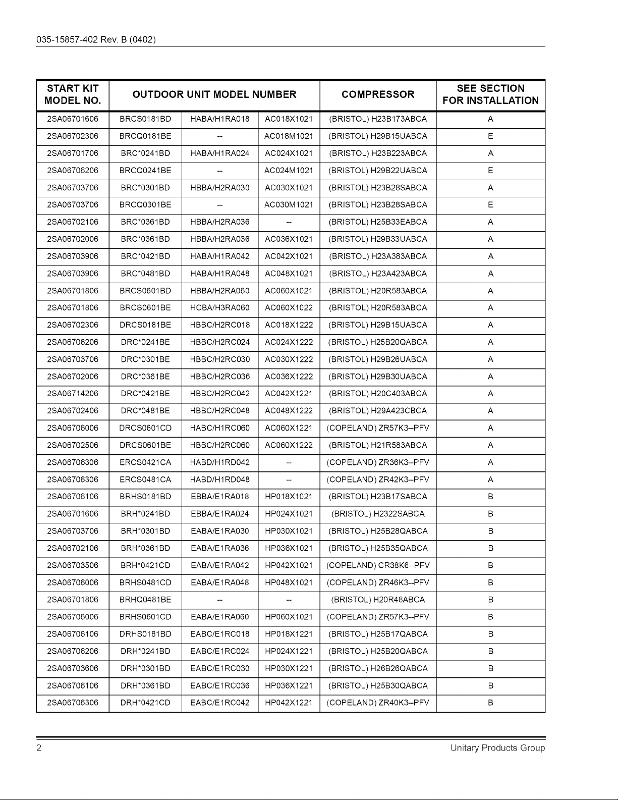
START
KIT
SEE
SECTION
MODEL
NO.
OUTDOOR
UNIT
MODEL
NUMBER
COMPRESSOR
FOR
INSTALLATION
2SA06701606
BRCS0181BD
HABA/H1RA018
|
ACO18X1021
(BRISTOL)
H23B173ABCA
A
2SA06702306
BRCQ0181BE
--
AC018M1021
(BRISTOL)
H29B15UABCA
E
2SA06701706
BRC*0241BD
HABA/H1RA024
|
AC024X1021
(BRISTOL)
H23B223ABCA
A
2SA06706206
BRCQ0241BE
--
AC024M1021
(BRISTOL)
H29B22UABCA
E
2SA06703706
BRC*0301BD
HBBA/H2RA030
|
ACO30X1021
(BRISTOL)
H23B28SABCA
A
2SA06703706
BRCQ0301BE
--
AC030M1021
(BRISTOL)
H23B28SABCA
E
2SA06702106
BRC*0361BD
HBBA/H2RA036
--
(BRISTOL)
H25B33EABCA
A
2SA06702006
BRC*0361BD
HBBA/H2RA036
|
ACO36X1021
(BRISTOL)
H29B33UABCA
A
2S5A06703906
BRC*0421BD
HABA/H1RA042
|
AC042X1021
(BRISTOL)
H23A383ABCA
A
2S5A06703906
BRC*0481BD
HABA/H1RA048
=|
AC048X1021
(BRISTOL)
H23A423ABCA
A
2S5A06701806
BRCS0601BD
HBBA/H2RAQ60
|
ACO60X1021
(BRISTOL)
H20R583ABCA
A
2S5A06701806
BRCS0601BE
HCBA/H3RA060
|
ACOGOX1022
(BRISTOL)
H20R583ABCA
A
2SA06702306
DRCS0181BE
HBBC/H2RC018
|
ACO18X1222
(BRISTOL)
H29B15UABCA
A
2SA06706206
DRC*0241BE
HBBC/H2RC024
|
AC024X1222
(BRISTOL)
H25B20QABCA
A
2SA06703706
DRC*0301BE
HBBC/H2RC030
|
ACO30X1222
(BRISTOL)
H29B26UABCA
A
2SA06702006
DRC*0361BE
HBBC/H2RC036
|
ACO36X1222
(BRISTOL)
H28B30UABCA
A
2SA06714206
DRC*0421BE
HBBC/H2RC042
|
AC0Q42X1221
(BRISTOL)
H20C403ABCA
A
2SA06702406
DRC*0481BE
HBBC/H2RC048
|
ACO048X1222
(BRISTOL)
H28A423CBCA
A
2SA06706006
DRCS0601CD
HABC/H1RCO6O
|
ACO60X1221
|
(COPELAND)
ZR57K3--PFV
A
2SA06702506
DRCS0601BE
HBBC/H2RCO060
|
ACO60X1222
(BRISTOL)
H21R583ABCA
A
2SA06
706306
ERCS0421CA
HABD/H1RD042
--
(COPELAND)
ZR36K3--PFV
A
2SA06
706306
ERCS0481CA
HABD/H1RD048
--
(COPELAND)
ZR42K3--PFV
A
2S5A06706106
BRHS0181BD
EBBA/E1RA018
HP018X1021
(BRISTOL)
H23B17SABCA
B
2SA06701606
BRH*0241BD
EBBA/E1RA024
HP024X1021
(BRISTOL)
H2322SABCA
B
2SA06703706
BRH*0301BD
EABA/E1RAQ30
HP030X1021
(BRISTOL)
H25B28QABCA
B
2SA06702106
BRH*0361BD
EABA/E1RA036
HP036X1021
(BRISTOL)
H25B35QABCA
B
2SA06703506
BRH*0421CD
EABA/E1RA042
HP042X1021
|
(COPELAND)
CR38K6--PFV
B
2SA06706006
BRHS0481CD
EABA/E1RA048
HP048X1021
|
(COPELAND)
ZR46K3--PFV
B
2S5A06701806
BRHQ0481BE
-- --
(BRISTOL)
H20R48ABCA
B
2SA06706006
BRHS0601CD
EABA/E1RAQ60
HPO60X1021
|
(COPELAND)
ZR57K3--PFV
B
2S5A06706106
DRHS0181BD
EABC/E1RC018
HP018X1221
(BRISTOL)
H25B17QABCA
B
2SA06706206
DRH*0241BD
EABC/E1RC024
HP024X1221
(BRISTOL)
H25B20QABCA
B
2SA06703606
DRH*0301BD
EABC/E1RC030
HP030X1221
(BRISTOL)
H26B26QABCA
B
2S5A06706106
DRH*0361BD
EABC/E1RC036
HP036X1221
(BRISTOL)
H25B30QABCA
B
2SA06
706306
DRH*0421CD
EABC/E1RC042
HP042X1221
|
(COPELAND)
ZR40K3--PFV
B
Unitary
Products
Group
035-15857-402
Rev.
B
(0402)
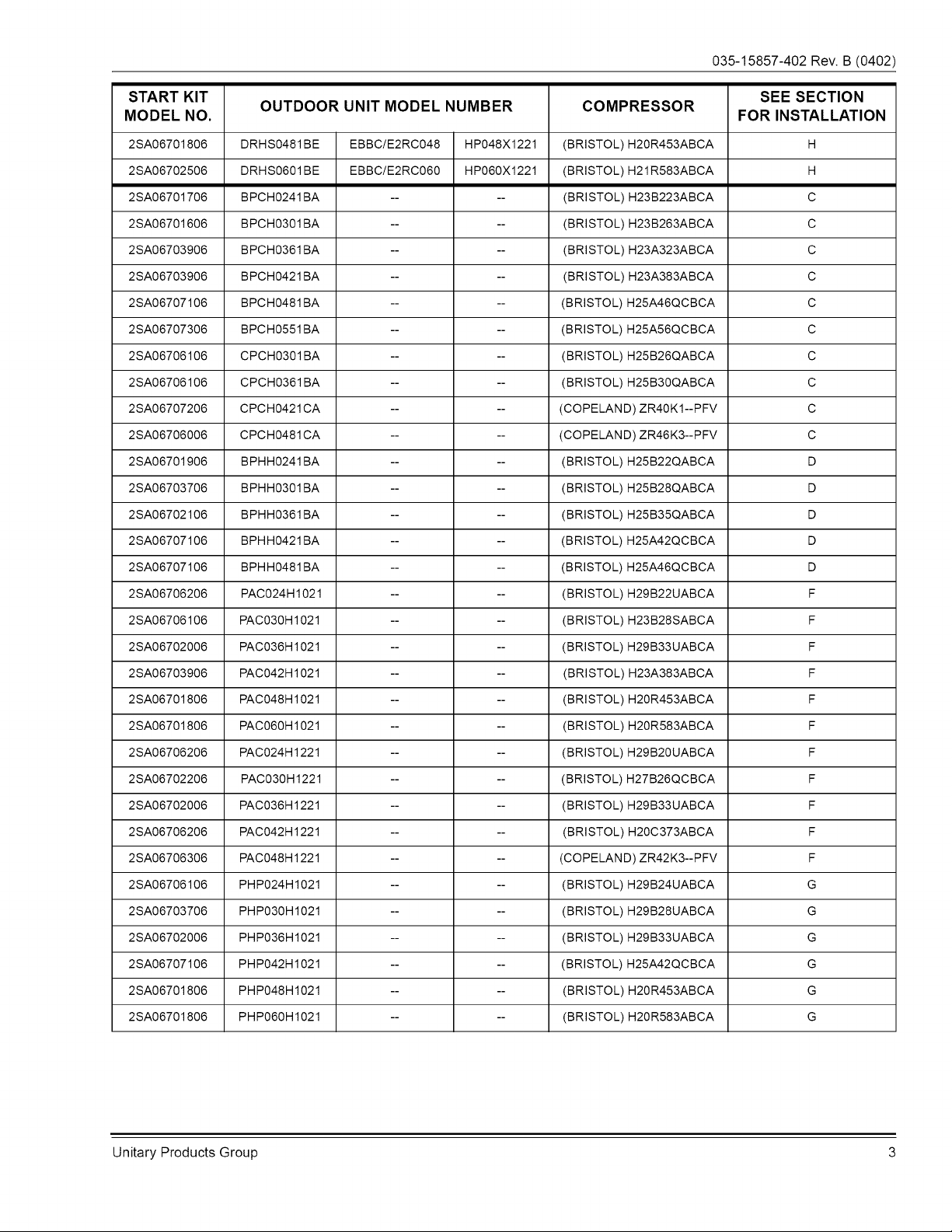
START
KIT
SEE
SECTION
MODEL
NO.
OUTDOOR
UNIT
MODEL
NUMBER
COMPRESSOR
FOR
INSTALLATION
2SA06701806
DRHS0481BE
EBBC/E2RC048
HP048X1221
(BRISTOL)
H20R453ABCA
H
2SA06702506
DRHS0601BE
EBBC/E2RC060
HP060X1221
(BRISTOL)
H21R583ABCA
H
2S5A06701706
BPCH0241BA
-- --
(BRISTOL)
H23B223ABCA
Cc
2SA06701606
BPCH0301BA
-- --
(BRISTOL)
H23B263ABCA
Cc
2SA06703906
BPCH0361BA
-- --
(BRISTOL)
H23A323ABCA
Cc
2SA06703906
BPCH0421BA
-- --
(BRISTOL)
H23A383ABCA
Cc
2SA06707
106
BPCH0481BA
-- --
(BRISTOL)
H25A46QCBCA
Cc
2SA06707306
BPCH0551BA
-- --
(BRISTOL)
H25A56QCBCA
Cc
2S5A06706106
CPCH0301BA
-- --
(BRISTOL)
H25B26QABCA
Cc
2S5A06706106
CPCH0361BA
-- --
(BRISTOL)
H25B30QABCA
Cc
2SA06707206
CPCH0421CA
-- --
(COPELAND)
ZR40K1--PFV
Cc
2SA06706006
CPCH0481CA
-- --
(COPELAND)
ZR46K3--PFV
Cc
2SA06701906
BPHH0241BA
-- --
(BRISTOL)
H25B22QABCA
D
2SA06703706
BPHH0301BA
-- --
(BRISTOL)
H25B28QABCA
D
2SA06702106
BPHH0361BA
-- --
(BRISTOL)
H25B35QABCA
D
2SA06707
106
BPHH0421BA
-- --
(BRISTOL)
H25A42QCBCA
D
2SA06707
106
BPHH0481BA
-- --
(BRISTOL)
H25A46QCBCA
D
2SA06706206
PAC024H1021
-- --
(BRISTOL)
H29B22UABCA
F
2SA06706106
PAC030H1021
-- --
(BRISTOL)
H23B28SABCA
F
2SA06702006
PAC036H
1021
-- --
(BRISTOL)
H29B33UABCA
F
2SA06703906
PAC042H1021
-- --
(BRISTOL)
H23A383ABCA
F
2S5A06701806
PAC048H1021
-- --
(BRISTOL)
H20R453ABCA
F
2S5A06701806
PACO60H1021
-- --
(BRISTOL)
H20R583ABCA
F
2SA06706206
PAC024H1221
-- --
(BRISTOL)
H29B20UABCA
F
2SA06
702206
PAC030H1221
-- --
(BRISTOL)
H27B26QCBCA
F
2SA06702006
PAC036H
1221
-- --
(BRISTOL)
H29B33UABCA
F
2SA06
706206
PAC042H1221
-- --
(BRISTOL)
H20C373ABCA
F
2SA06
706306
PAC048H1221
-- --
(COPELAND)
ZR42K3--PFV
F
2S5A06706106
PHP024H1021
-- --
(BRISTOL)
H29B24UABCA
G
2SA06703706
PHP030H1021
-- --
(BRISTOL)
H29B28UABCA
G
2SA06702006
PHP036H1021
-- --
(BRISTOL)
H29B33UABCA
G
2SA06707
106
PHP042H1021
-- --
(BRISTOL)
H25A42QCBCA
G
2SA06701806
PHP048H1021
-- --
(BRISTOL)
H20R453ABCA
G
2SA06701806
PHPO60H1021
-- --
(BRISTOL)
H20R583ABCA
G
Unitary
Products
Group
035-15857-402
Rev.
B
(0402)
SECTION
A
BRC(S,Q),
HBA, HRA,
ERCS,
HBD, HRD,
DRC(S,Q),
HBC,
HRC
&
AC(10,12)
SERIES
SPLIT
AIR
CONDITIONERS
Pre-drilled
pilot
holes
are
provided
in
the
control
box.
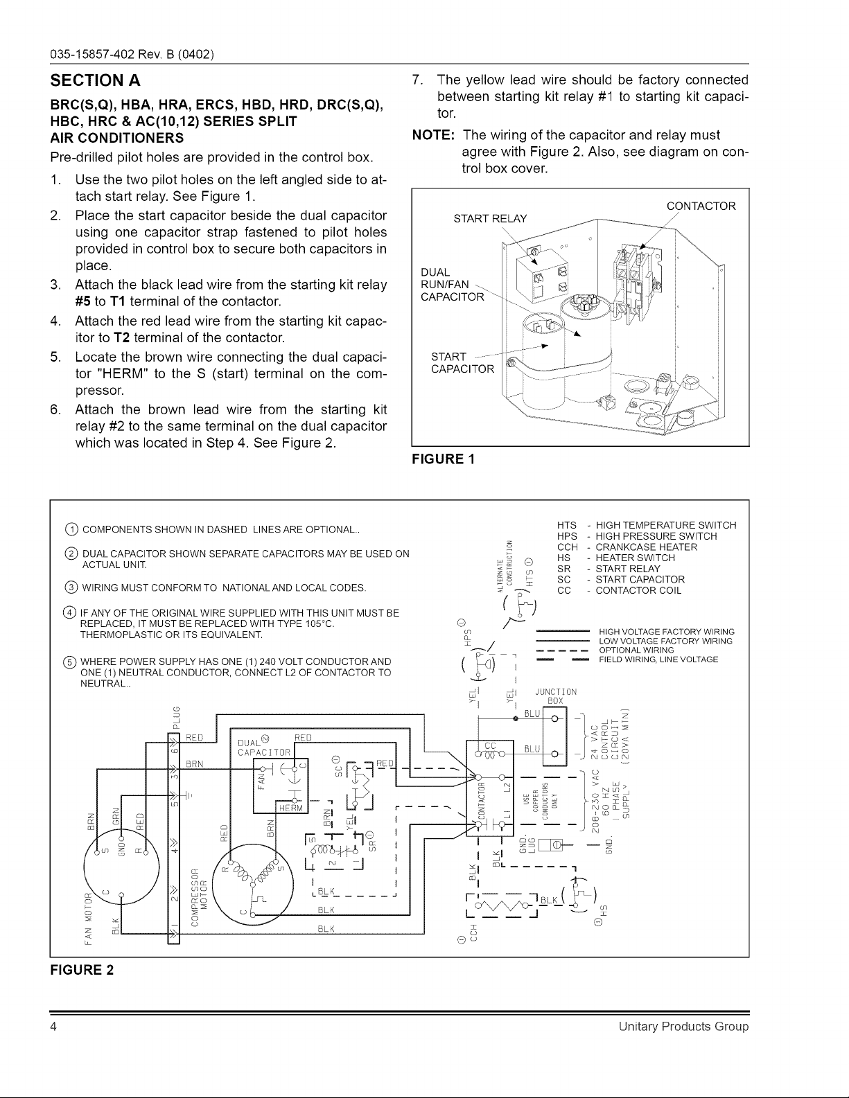
1.
Use
the
two
pilot
holes
on
the
left
angled
side
to
at-
7.
The
yellow
lead
wire
should
be
factory
connected
between
starting
kit
relay
#1
to
starting
kit
capaci-
tor.
NOTE:
The
wiring
of
the
capacitor
and
relay
must
agree
with
Figure
2.
Also,
see
diagram
on
con-
trol
box
cover.
tach
start
relay.
See
Figure
1.
; ;
CONTACTOR
2.
Place
the
start
capacitor
beside
the
dual
capacitor
START
RELAY
using
one
capacitor
strap
fastened
to
pilot
holes
provided
in
control
box
to
secure
both
capacitors
in
place.
. . .
DUAL
3.
Attach
the
black
lead
wire
from
the
starting
kit
relay
RUN/FAN
~
|.
#5
to
T1
terminal
of
the
contactor.
CAPACITOR
4.
Attach
the
red
lead
wire
from
the
starting
kit
capac-
itor
to
T2
terminal
of
the
contactor.
5.
Locate
the
brown
wire
connecting
the
dual
capaci-
START
"7
tor
"HERM"
to
the
S
(start)
terminal
on
the
com-
CAPACITOR
TT
pressor.
6.
Attach
the
brown
lead
wire
from
the
starting
kit
|
2
2
2
2
2
Oe
relay
#2
to
the
same
terminal
on
the
dual
capacitor
which
was
located
in
Step
4.
See
Figure
2.
FIGURE
1
HTS
-
HIGH
TEMPERATURE
SWITCH
G)
COMPONENTS
SHOWN
IN
DASHED
LINES
ARE
OPTIONAL.
:
HPS
_
HIGH
PRESSURE
SWITCH
(2)
DUAL
CAPACITOR
SHOWN
SEPARATE
CAPACITORS
MAY
BE
USED
ON
=
6
nS
:
NEATER
Swit
ACTUAL
UNIT,
s=
SR_
-
START
RELAY
&&
&
SC
-
START
CAPACITOR
@)
WIRING
MUST
CONFORM
TO
NATIONAL
AND
LOCAL
CODES.
3°
CC
-
CONTACTOR
COIL
@)
IF
ANY
OF
THE
ORIGINAL
WIRE
SUPPLIED
WITH
THIS
UNIT
MUST
BE
(
t
)
REPLACED,
IT
MUST
BE
REPLACED
WITH
TYPE
105°C.
a
,
HIGH
VOLTAGE
FACTORY
WIRING
Wy
THERMOPLASTIC
OR
ITS
EQUIVALENT.
©
a
eS Om
wiking
fo
ae
eee
OPTIONAL
WIRING
WHERE
POWER
SUPPLY
HAS
ONE
(1)
240
VOLT
CONDUCTOR
AND
(
}
0;
mm
FIELD
WIRING,
LINE
VOLTAGE
ONE
(1)
NEUTRAL
CONDUCTOR,
CONNECT
L2
OF
CONTACTOR
TO
NEUTRAL.
| ,
JUNCTION
: |
=|
cam
BOX
o
—
=
oF
flo
“|
aLe
=
ges
RED
puaL®
BER
te
ALU
Ik
SES
©
sen
CAPACITOR
6
on
OBPO
O|
J
ASGR
Oo
7
ae
cad
ae
~
>
Sey
Sle
>of
—
—
72
i
bef
g
>
ts
li
_
S
BESS
Qisa
0
HERM
|
Sy
Jo.
---K6
S
"828
None
zl
\
NGF
8
ao?
_@
|
dS
| |
ao
_
2
»
!
|
esl
—8
a
{
<I
OR
me me
me
mmm
1
S
m
>
>|
BS
ye
ff)
S
“|
ES
A
ee
=
x
8
—
©
1
_
aa
=
z
mo
oO
=
ey
Oo
FIGURE
2
Unitary
Products
Group
035-15857-402
Rev.
B
(0402)
SECTION
B
BRH,
EBA, ERA,
DRH,
EBC,
ERC
&
HP(10,12)
SERIES
SPLIT
HEAT
PUMPS
Pre-drilled
pilot
holes
are
provided
in
the
control
box.
NOTE:
On
units
which
have
a
solid
state
start
device,
remove
5the
device
and
the
red
and
brown
wir-
ing
connections
to
the
dual
capacitor.
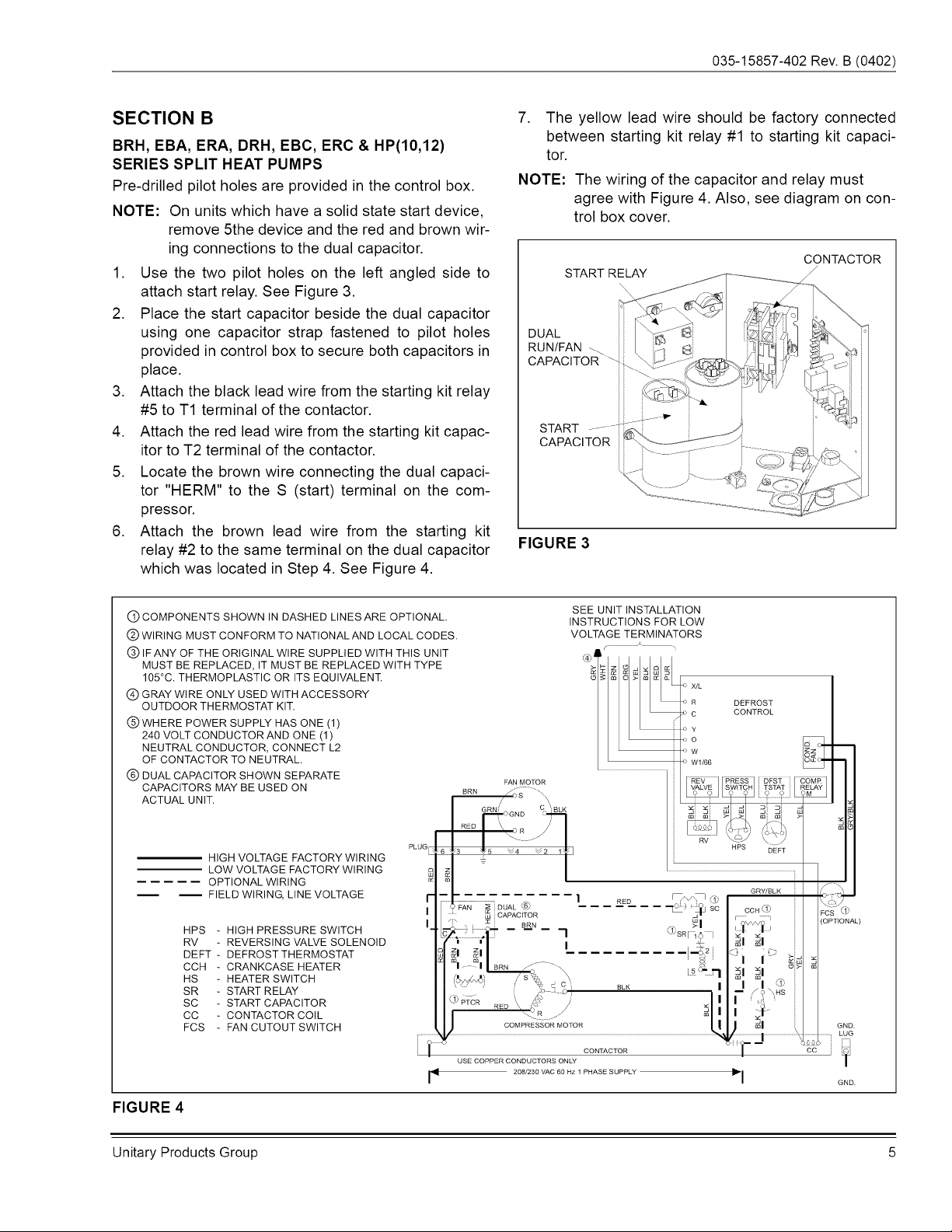
1.
Use
the
two
pilot
holes
on
the
left
angled
side
to
attach
start
relay.
See
Figure
3.
2.
Place
the
start
capacitor
beside
the
dual
capacitor
using
one
capacitor
strap
fastened
to
pilot
holes
provided
in
control
box
to
secure
both
capacitors
in
place.
3.
Attach
the
black
lead
wire
from
the
starting
kit
relay
#5
to
T1
terminal
of
the
contactor.
4.
Attach
the red
lead
wire
from
the
starting
kit
capac-
itor
to
T2
terminal
of
the
contactor.
5.
Locate
the
brown
wire
connecting
the
dual
capaci-
tor
"HERM"
to
the
S
(start)
terminal
on
the
com-
pressor.
6.
Attach
the
brown
lead
wire
from
the
starting
kit
relay
#2
to
the
same
terminal
on
the
dual
capacitor
which
was
located
in
Step
4.
See
Figure
4.
7.
The
yellow
lead
wire
should
be
factory
connected
between
starting
kit
relay
#1
to
starting
kit
capaci-
tor.
NOTE:
The
wiring
of
the
capacitor
and
relay
must
agree
with
Figure
4.
Also,
see
diagram
on
con-
trol
box
cover.
CONTACTOR
START
RELAY
CAPACITOR
FIGURE
3
@
COMPONENTS
SHOWN
IN
DASHED
LINES
ARE
OPTIONAL.
@
WIRING
MUST
CONFORM
TO
NATIONAL
AND
LOCAL
CODES.
@
IF
ANY
OF
THE
ORIGINAL
WIRE
SUPPLIED
WITH
THIS
UNIT
SEE
UNIT
INSTALLATION
INSTRUCTIONS
FOR
LOW
VOLTAGE
TERMINATORS
c
\
w
(
LOW
VOLTAGE
FACTORY
WIRING
--c-C
OPTIONAL
WIRING
—
FIELD
WIRING,
LINE
VOLTAGE
HPS
-
HIGH
PRESSURE
SWITCH
RV
-
REVERSING
VALVE
SOLENOID
DEFT
-
DEFROST
THERMOSTAT
CCH
-
CRANKCASE
HEATER
HS
=
-
HEATER
SWITCH
SR
-
START
RELAY
SC
-
START
CAPACITOR
CC
-
CONTACTOR
COIL
FCS
-
FAN
CUTOUT
SWITCH
MUST
BE
REPLACED,
IT
MUST
BE
REPLACED
WITH
TYPE
“zlelz|
9]
alvlole
105°C.
THERMOPLASTIC
OR
ITS
EQUIVALENT.
858]
85
3/25
|
@
GRAY
WIRE
ONLY
USED
WITH
ACCESSORY
OUTDOOR
THERMOSTAT
KIT.
[;
:
CONTROL
@
WHERE
POWER
SUPPLY
HAS
ONE
(1)
sy
240
VOLT
CONDUCTOR
AND
ONE
(1)
SO
NEUTRAL
CONDUCTOR,
CONNECT
L2
>
Ww
3,
OF
CONTACTOR
TO
NEUTRAL.
>
WHI66
Bic
©
DUAL
CAPACITOR
SHOWN
SEPARATE
CAPACITORS
MAY
BE
USED
ON
pen
mene
Nave
|
|
SW
RELAY
ACTUAL
UNIT.
———
8
+t
4
e
pomocno
BL
El
@
Je
RED
\
R
als
Ne
PLUG
hg
Wa
B.
Vv4_
V2
i¥)
HIGH
VOLTAGE
FACTORY
WIRING
=
go
z
a x
© a
GRY/BLK
|
7
\O4
I
oon
rcs
D
,
(OPTIONAL)
i
t
ty
i
x x
“)
ck
ED
lof
eal
%
x
x
o>|
,
al
al
Z
0
oo
Lay
&
i]
tote
)
oo
\
&
=
9
NHS
®
ptcr
\
&
yr
fae
RED.
&
o
Re
Wyt
oF
COMPRESSOR
MOTOR
l
J
zl
GND.
:
LUG
~
ice
bens
:
CONTACTOR
cc
USE
COPPER
CONDUCTORS
ONLY
i
208/230
VAC
60
Hz
1
PHASE
SUPPLY
|
FIGURE
4
Unitary
Products
Group
035-15857-402
Rev.
B
(0402)
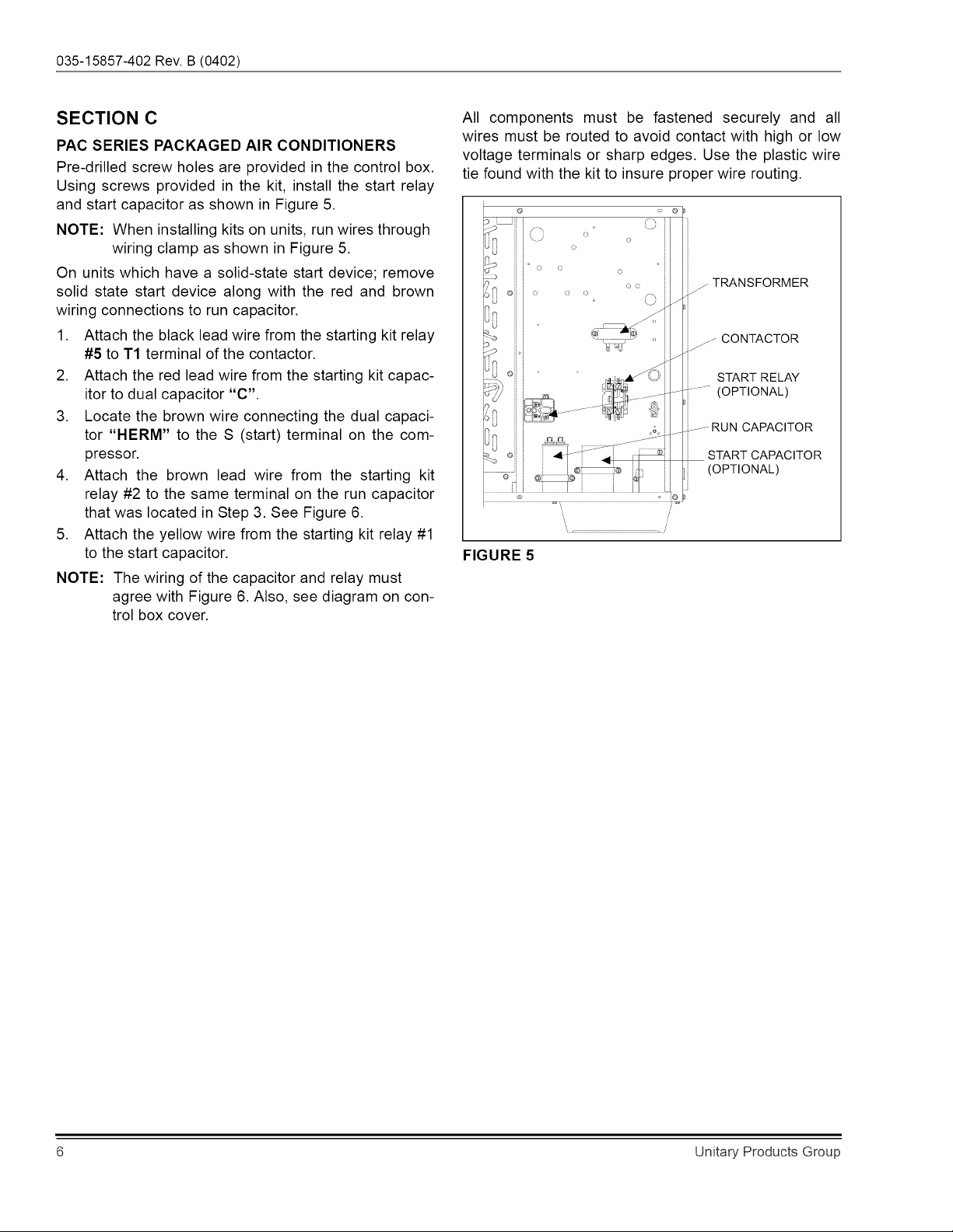
SECTION
C
PAC
SERIES
PACKAGED
AIR
CONDITIONERS
Pre-drilled
screw
holes
are
provided
in
the
control
box.
Using
screws
provided
in
the
kit,
install
the
start
relay
and
start
capacitor
as
shown
in
Figure
5.
NOTE:
When
installing
kits
on
units,
run
wires
through
wiring
clamp
as
shown
in
Figure
5.
On
units
which
have
a
solid-state
start
device;
remove
solid
state
start
device
along
with
the
red
and
brown
wiring
connections
to
run
capacitor.
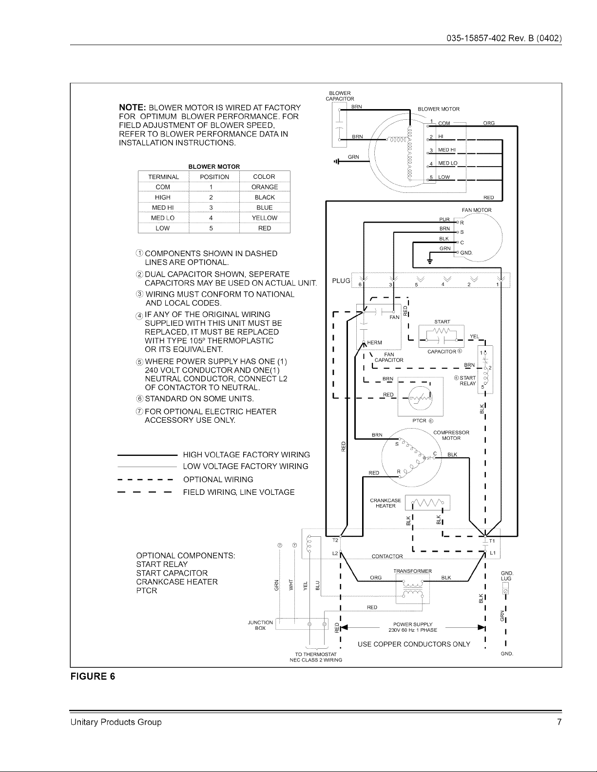
1.
Attach
the
black
lead
wire
from
the
starting
kit
relay
#5
to
T1
terminal
of
the
contactor.
2.
Attach
the
red
lead
wire
from
the
starting
kit
capac-
itor
to
dual
capacitor
“C”.
3.
Locate
the
brown
wire
connecting
the
dual
capaci-
tor
“HERM”
to
the
S
(start)
terminal
on
the
com-
pressor.
4.
Attach
the
brown
lead
wire
from
the
starting
kit
relay
#2
to
the
same
terminal
on
the
run
capacitor
that
was
located
in
Step
3.
See
Figure
6.
5.
Attach
the
yellow
wire
from
the
starting
kit
relay
#1
to
the
start
capacitor.
NOTE:
The
wiring
of
the
capacitor
and
relay
must
agree
with
Figure
6.
Also,
see
diagram
on
con-
trol
box
cover.
All
components
must
be
fastened
securely
and
_
ail
wires
must
be
routed
to
avoid
contact
with
high
or
low
voltage
terminals
or
sharp
edges.
Use
the
plastic
wire
tie
found
with
the
kit
to
insure
proper
wire
routing.
:
o
8h
a
O
3
~
o
)
6
7.
oo
_-
TRANSFORMER
of)
|
«
A
v
Ka
,
Ss
_>
CONTACTOR
—°
_
START
RELAY
=)
~~
(OPTIONAL)
lo
tn
__-
RUN
CAPACITOR
a
START
CAPACITOR
=
(OPTIONAL)
FIGURE
5
Unitary
Products
Group
035-15857-402
Rev.
B
(0402)
NOTE:
BLOWER MOTOR
IS
WIRED
AT
FACTORY
FOR
OPTIMUM
BLOWER
PERFORMANCE.
FOR
FIELD
ADJUSTMENT
OF
BLOWER
SPEED,
REFER
TO
BLOWER
PERFORMANCE
DATA
IN
INSTALLATION
INSTRUCTIONS.
BLOWER
MOTOR
TERMINAL
POSITION
COLOR
COM
1
ORANGE
HIGH
2
BLACK
MED
HI
3
BLUE
MED
LO
4
YELLOW
LOW
5
RED
@
COMPONENTS
SHOWN
IN
DASHED
LINES
ARE
OPTIONAL.
@DUAL
CAPACITOR
SHOWN,
SEPERATE
CAPACITORS
MAY
BE
USED
ON
ACTUAL
UNIT.
@®
WIRING
MUST
CONFORM
TO
NATIONAL
AND
LOCAL
CODES.
@
IF
ANY
OF
THE
ORIGINAL
WIRING
SUPPLIED
WITH
THIS
UNIT
MUST
BE
REPLACED,
IT
MUST
BE
REPLACED
WITH
TYPE
105°
THERMOPLASTIC
OR
ITS
EQUIVALENT.
6)
WHERE
POWER
SUPPLY
HAS
ONE
(1)
240
VOLT
CONDUCTOR
AND
ONE(1)
NEUTRAL
CONDUCTOR,
CONNECT
L2
OF
CONTACTOR
TO
NEUTRAL.
©
STANDARD
ON
SOME
UNITS.
@
FOR
OPTIONAL
ELECTRIC
HEATER
ACCESSORY
USE
ONLY.
HIGH
VOLTAGE
FACTORY
WIRING
LOW
VOLTAGE
FACTORY
WIRING
OPTIONAL
WIRING
FIELD
WIRING,
LINE
VOLTAGE
BLOWER
CAPACITOR
BLOWER
MOTOR
ORG
LOST
COO
STO
IT
RED
PUR
[oe
\
BRN
os
\
BLK
|.
|
c
}
GRN
é
ce
/
_
Ne
¥
vw
YW
PLUG,
6 3 5
4
2
1
:
PTCR
©
"COMPRESSOR
MOTOR
RED
CRANKCASE
HEATER
)
/
Wf]
NZ
© @
2
T2
*
T1
OPTIONAL
COMPONENTS:
|
Lg
2K
contactor.
AM
START
RELAY
i
I
I
START
CAPACITOR
i
ore
|S
Re
;
CRANKCASE
HEATER
zo:
PTCR
6
=
=
|
JUNCTION
BOX
TO
THERMOSTAT
BLU
POWER
SUPPLY
230V
60
Hz
1
PHASE
USE
COPPER
CONDUCTORS
ONLY
NEC
CLASS
2
WIRING
FIGURE
6
Unitary
Products
Group
035-15857-402
Rev.
B
(0402)
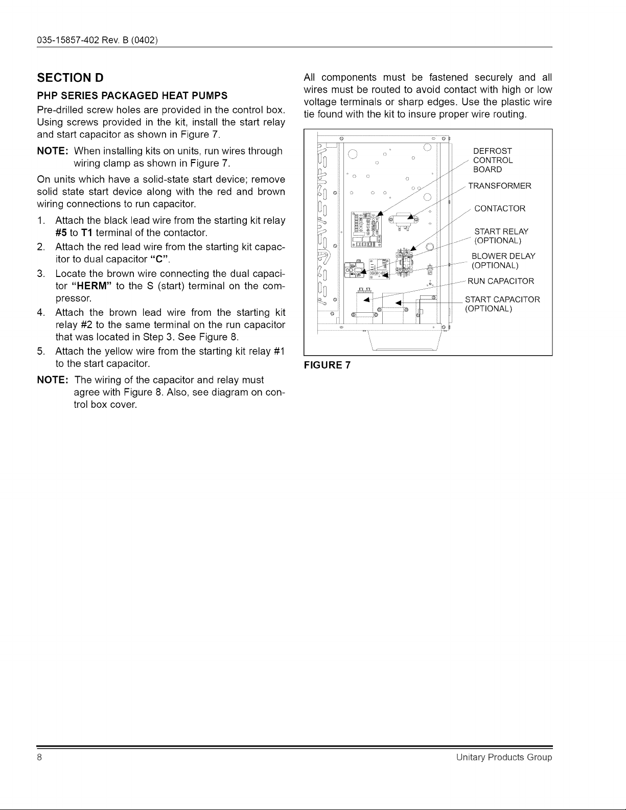
SECTION
D
PHP
SERIES
PACKAGED
HEAT
PUMPS
Pre-drilled
screw
holes
are
provided
in
the
control
box.
Using
screws
provided
in
the
kit,
install
the
start
relay
and
start
capacitor
as
shown
in
Figure
7.
NOTE:
When
installing
kits
on
units,
run
wires
through
wiring
clamp
as
shown
in
Figure
7.
On
units
which
have
a
solid-state
start
device;
remove
solid
state
start
device
along
with
the
red
and
brown
wiring
connections
to
run
capacitor.
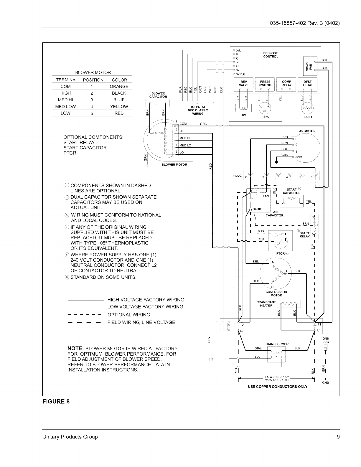
1.
Attach
the
black
lead
wire
from
the
starting
kit
relay
#5
to
T1
terminal
of
the
contactor.
2.
Attach
the
red
lead
wire
from
the
starting
kit
capac-
itor
to
dual
capacitor
“C”.
3.
Locate
the
brown
wire
connecting
the
dual
capaci-
tor
“HERM”
to
the
S
(start)
terminal
on
the
com-
pressor.
4.
Attach
the
brown
lead
wire
from
the
starting
kit
relay
#2
to
the
same
terminal
on
the
run
capacitor
that
was
located
in
Step
3.
See
Figure
8.
5.
Attach
the
yellow
wire
from
the
starting
kit
relay
#1
to
the
start
capacitor.
NOTE:
The
wiring
of
the
capacitor
and
relay
must
agree
with
Figure
8.
Also,
see
diagram
on
con-
trol
box
cover.
All
components
must
be
fastened
securely
and
_
ail
wires
must
be
routed
to
avoid
contact
with
high
or
low
voltage
terminals
or
sharp
edges.
Use
the
plastic
wire
tie
found
with
the
kit
to
insure
proper
wire
routing.
8
o
ef
DEFROST
CONTROL
BOARD
_~
TRANSFORMER
Z
CONTACTOR
START
RELAY
|_—-~
(OPTIONAL)
BLOWER
DELAY
-#-"~
(OPTIONAL)
_|--RUN
CAPACITOR
START
CAPACITOR
(OPTIONAL)
FIGURE
7
Unitary
Products
Group
035-15857-402
Rev.
B
(0402)
—?
XML
—oR
DEFROST
e¢
CONTROL
BLK
=
Of
ak
BLOWER
MOTOR
ae
os
TERMINAL
|
POSITION
|
COLOR
REV
Press
||
DFST
COM
4
ORANGE
x
VALVE
SWITCH
T’
STAT
nich
<____BLACK
cameron
i 2 2
MED
Hi
3
BLUE
7
IEEE
e a
@
MED
LOW
4
YELLOW
TO
T'STAT
4s
NEC
CLASS
2
\
j
LOW
5
RED
WIRING
RV
—~
HPS
DEFT
com—_
ore
HI
FAN
MOTOR
OPTIONAL
COMPONENTS:
MED
HI
PUR
Te
\
START RELAY
WEDLO
BRN
|g
\
START
CAPACITOR
aux
|.
|
PTCR
LO
|
ct
GND
ZY
BLOWER
MOTOR
a
-
ow
_S~SdS
Vv
©
COMPONENTS
SHOWN
IN
DASHED
LINES
ARE
OPTIONAL.
@)
DUAL
CAPACITOR
SHOWN
SEPARATE
CAPACITORS
MAY
BE
USED
ON
ACTUAL
UNIT.
@)
WIRING
MUST
CONFORM
TO
NATIONAL
AND
LOCAL
CODES.
@
|F
ANY
OF
THE
ORIGINAL
WIRING
SUPPLIED
WITH
THIS
UNIT
MUST
BE
REPLACED,
IT
MUST
BE
REPLACED
WITH
TYPE
105°
THERMOPLASTIC
OR
ITS
EQUIVALENT.
nn
@)
WHERE
POWER
SUPPLY
HAS
ONE
(1)
240
VOLT
CONDUCTOR
AND ONE
(1)
NEUTRAL
CONDUCTOR,
CONNECT
L2
OF
CONTACTOR
TO
NEUTRAL.
©»
STANDARD
ON
SOME
UNITS.
RELAY
©
HIGH
VOLTAGE
FACTORY
WIRING
LOW
VOLTAGE
FACTORY
WIRING
4
soc
cc
OPTIONAL
WIRING
a
— —
—
—_
FIELD
WIRING,
LINE
VOLTAGE
CRANKCASE
|
HEATER
RED
Sood
GRY
o
a
a
z
z
wn
7
9
2
i=
mi
a
wo
er
x
NOTE:
BLOWER
MOTOR
IS
WIRED
AT
FACTORY
|
5g
|
7
FOR
OPTIMUM
BLOWER
PERFORMANCE.
FOR
——
FIELD
ADJUSTMENT
OF
BLOWER
SPEED,
et
REFER
TO
BLOWER
PERFORMANCE
DATAIN
l
I I
INSTALLATION
INSTRUCTIONS.
POWER
SUPPLY
I*
230V
60
Hz
1
PH
a
| '
USE
COPPER
CONDUCTORS
ONLY
FIGURE
8
Unitary
Products
Group
9
035-15857-402
Rev.
B
(0402)
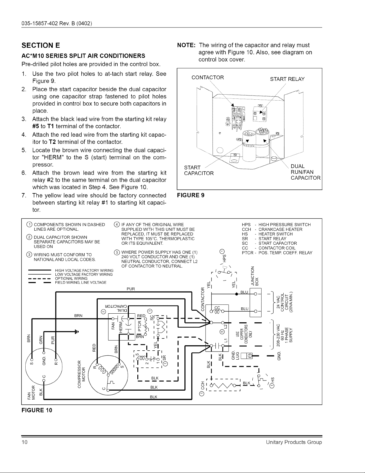
SECTION
E
AC*M10
SERIES
SPLIT
AIR
CONDITIONERS
Pre-drilled
pilot
holes
are
provided
in
the
control
box.
1.
2.
Use
the
two
pilot
holes
to
at-tach
start
relay.
See
Figure
9.
Place
the
start
capacitor
beside
the
dual
capacitor
using
one
capacitor
strap
fastened
to
pilot
holes
provided
in
control
box
to
secure
both
capacitors
in
place.
Attach
the
black
lead
wire
from
the
starting
kit
relay
#5
to
T1
terminal
of
the
contactor.
Attach
the
red
lead
wire
from
the
starting
kit
capac-
itor
to
T2
terminal
of
the
contactor.
Locate
the
brown
wire
connecting
the
dual
capaci-
tor
"HERM"
to
the
S
(start)
terminal
on
the
com-
pressor.
Attach
the
brown
lead
wire
from
the
starting
kit
relay
#2
to
the
same
terminal
on
the
dual
capacitor
which
was
located
in
Step
4.
See
Figure
10.
The
yellow
lead
wire
should
be
factory
connected
between
starting
kit
relay
#1
to
starting
kit
capaci-
tor.
NOTE:
The
wiring
of
the
capacitor
and
relay
must
agree
with
Figure
10.
Also,
see
diagram
on
control
box
cover.
CONTACTOR
START RELAY
START
DUAL
CAPACITOR
RUN/FAN
CAPACITOR
FIGURE
9
G)
COMPONENTS
SHOWN
INDASHED
—
@)
IF
ANY
OF
THE
ORIGINAL
WIRE
HPS
-
HIGH
PRESSURE
SWITCH
LINES
ARE
OPTIONAL.
SUPPLIED
WITH
THIS
UNIT
MUST
BE
CCH
-
CRANKCASE
HEATER
REPLACED,
IT
MUST
BE
REPLACED
HS
-
HEATER
SWITCH
(2)
DUAL
CAPACITOR
SHOWN
WITH
TYPE
105°C.
THERMOPLASTIC
SR
-
START
RELAY
CEL
ONE
CAPACITORS
MAY
BE
OR
ITS
EQUIVALENT.
SC
-
START
CAPACITOR
CC
-
CONTACTOR
COIL
WHERE
POWER
SUPPLY
HAS
ONE
(1)
©
PTCR
-
POS.
TEMP.
COEFF.
RELAY
©
NATION
AID
LOCAL
CODES
240
VOLT
CONDUCTOR
AND
ONE
(1)
%
NEUTRAL
CONDUCTOR,
CONNECT
L2
=
OF
CONTACTOR
TO
NEUTRAL.
ey
N
2
HIGH
VOLTAGE
FACTORY
WIRING
{
ono
°
LOW
VOLTAGE
FACTORY
WIRING
r
\
/
7
Ee
=——=——
=
OPTIONAL
WIRING
|
_
|
2x
—
mee
§=FIELD
WIRING,
LINE
VOLTAGE
iT
a 2
9
PUR
&
>I >|
BLU
~
5
°
O-
=~]
odkz2
s
SE35
YOLIOVEYD
Sf
Tce
BLU
ASRS
®
qwnd
©
©)
Cfo
O-
=
Orn
BRN
Ore
Rr
—
ze
x
$
|
|
—
D>
O—__
z &
e
| |
Le)
N
we
2
oy >.
i
x=
_
| 1
@)
ww
#
5
3 =
NN
2
a
BRN
lg!
moe
_
-Sgo
ages
1
|
~
—I
8
2”
a
a
iy
a
8 z
wy
,
PP
—_—
—
Ww
MM
—
.
i's
I 1
St
§2L1O—
z
n = x
9
x
/@
a
Ie
AS)
|
al
Loe
2S
q
I |
4
an
N
zg
a
r$-----
1!
2
5
Bl
OA
Aom
Bike
/
Oo oO
BLK
Oo,
“MMe
1
©
BLK
Oo
FIGURE
10
10
Unitary
Products
Group
035-15857-402
Rev.
B
(0402)
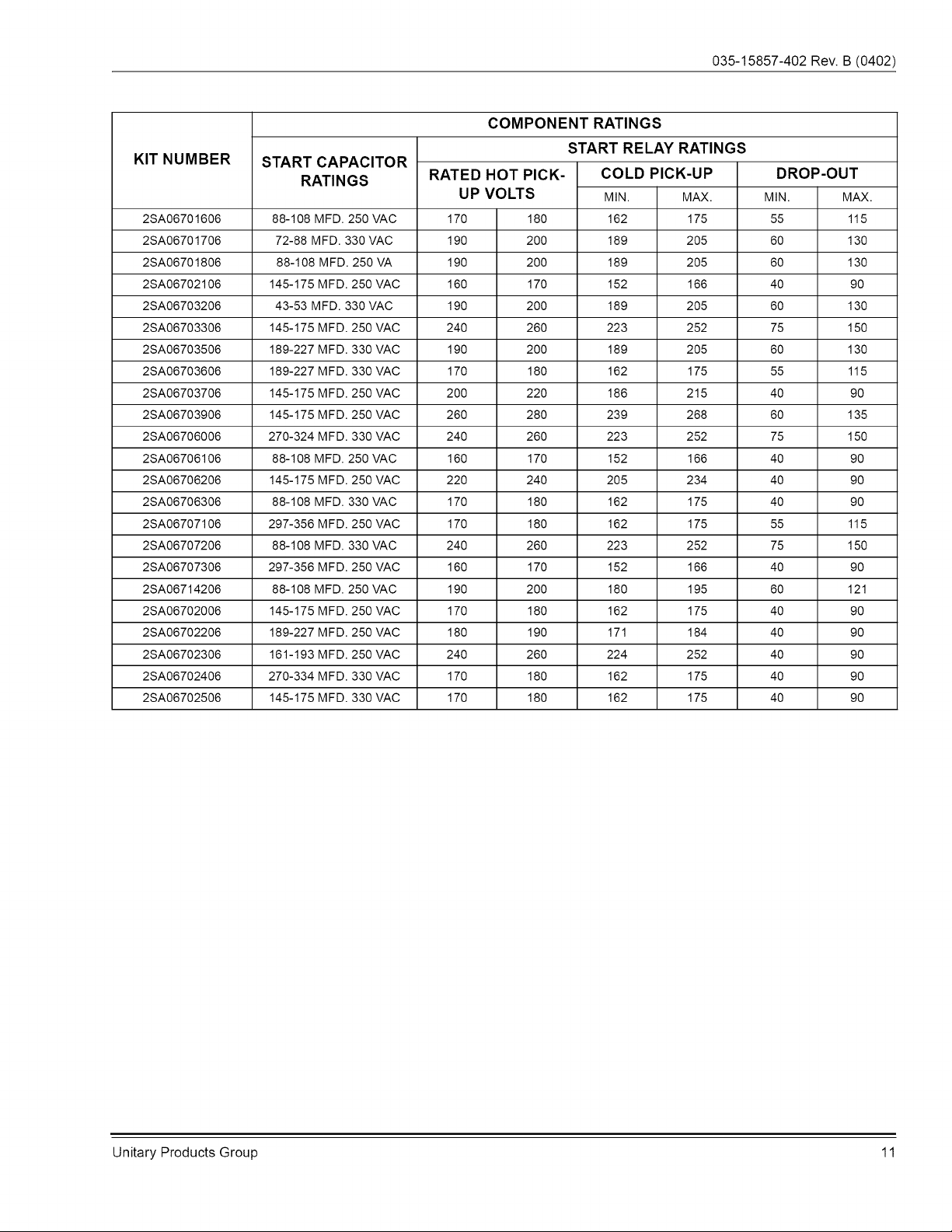
COMPONENT
RATINGS
KIT
NUMBER
START
CAPACITOR
START
RELAY
RATINGS
RATINGS
RATED
HOT
PICK-
COLD
PICK-UP
DROP-OUT
UP
VOLTS
MIN.
MAX.
MIN.
MAX.
2SA06701606
88-108
MFD.
250
VAC
170
180
162
175
55
115
2SA06701706
72-88
MFD.
330
VAC
190
200
189
205
60
130
2SA06701806
88-108
MFD.
250
VA
190
200
189
205
60
130
2SA06702106
145-175
MED.
250
VAC
160 170 152 166
40 90
2SA06703206
43-53
MED.
330
VAC
190
200
189
205
60
130
2SA06703306
145-175
MED.
250
VAC
240 260 223 252
75
150
2SA06703506
189-227
MED.
330
VAC
190
200
189
205
60
130
2SA06703606
189-227
MED.
330
VAC
170
180
162 175
55
115
2SA06703706
145-175
MED.
250
VAC
200 220
186
215
40 90
2SA06703906
145-175
MED.
250
VAC
260 280 239 268
60
135
2SA06706006
270-324
MFD.
330
VAC
240 260 223 252
75
150
2SA06706106
88-108
MFD.
250
VAC
160 170 152 166
40 90
2SA06706206
145-175
MED.
250
VAC
220 240 205 234
40 90
2SA06706306
88-108
MFD.
330
VAC
170
180
162 175
40 90
2SA06707106
297-356
MFD.
250
VAC
170
180
162
175
55
115
2SA06707206
88-108
MFD.
330
VAC
240 260 223 252
75
150
2SA06707306
297-356
MFD.
250
VAC
160 170 152 166
40 90
2SA06714206
88-108
MFD.
250
VAC
190
200
180 195
60
121
2SA06702006
145-175
MED.
250
VAC
170
180
162
175
40 90
2SA06702206
189-227
MED.
250
VAC
180
190
171
184
40 90
2SA06702306
161-193
MED.
250
VAC
240 260 224 252
40 90
2SA06702406
270-334
MFD.
330
VAC
170
180
162
175
40 90
2SA06702506
145-175
MED.
330
VAC
170
180
162 175
40 90
Unitary
Products
Group
11

NOTES
Subject
to
change
without
notice.
Printed
in
U.S.A.
035-15857-402
Rev.
B
(0402)
Copyright
©
by
York
International
Corp.
2002.
All
rights
reserved.
Supersedes:
035-15857-402
Rev.
A
(0101
Unitary
5005
Norman
Product
York
OK
Group
Drive
73069