Loading ...
Loading ...
Loading ...
3. Ifthecuttingattachmentrotateswhentheengineidles,turnthe
idlespeedscrewcounterclockwise1/8ofaturnatatime(as
needed),toreduceidlespeed.
Checkingthefuel,cleaningtheairfilter,andadjustingtheidlespeed
shouldsolvemostengineproblems.Ifnotandallofthefollowing
aretrue:
• theenginewillnotidle
• theenginehesitatesorstallsonacceleration
• thereisalossofenginepower
Havethecarburetoradjustedbyanauthorizedservicedealer.
ROCKER ARM CLEARANCE
_I ARNING: TOavoid serious personal injury, alwaysturn your
tr mmer off and a ow t to coo before you c eanor manta n t.
This requires disassembly of the engine. If you feel unsure or
unqualified to perform this, take the unit to a Sears or other qualified
service center.
NOTE: Inspect the valve to rocker arm clearance with a feeler
gauge after the first 25 hours of operation and then every
25 hours of operation thereafter.
• The engine must be cold when checking or adjusting the valve
clearance.
• This task should be performed inside in a clean, dust free area.
1. Remove the two (2) screws on back of the engine cover and the
one on the front of the engine cover with a Flat-head or T-25
Torx screwdriver (Fig. 27). Remove Screws
2. Remove the engine cover
(Fig. 28).
3. Disconnect the spark plug
wire.
4. Clean dirt from around the
spark plug. Remove the
spark plug from the
cylinder head by turning a Fig_27
5/8 in. socket
counterclockwise. Engine
Cover
5. Clean dirt from around the
rocker arm cover. Remove
the screw holding the
rocker arm cover with a
large flat blade
screwdriver or Torx T-25
bit (Fig. 29). Remove the
rocker arm cover and Fig. 28
gasket.
6. Pull the starter rope Screw_,_,
slowly to bring the piston Rocker Arm
to the top of its travel, Cover
(known as top dead
center). Check that: Spark
• The piston isat the top of its Plug
travel. This should be done
by looking into the spark
plug hole. (Fig.29) Fig. 29
Adjusting Nuts
• Both rocker arms move
freely, and both valves are
INTAKE
closed
If these statements are EXHAUST
not true, repeat step 6. Rocker t_V\
7. Slide the feeler gauge Arms
between the rocker arm
and the top of each valve
stem. Measure the Fig. 30
clearance between the valve stem and rocker arm (Fig. 31).
Measure both the intake and exhaust valves.
The recommended clearance for both intake and exhaust is .003 - .006 in.
(.076 - 0.152 ram). Use a standard automotive .005 in. (0.127 mm) feeler
gauge. The feeler gauge should slide between the rocker arm and valve
stem with a slight amount of resistance, without binding. Figure30 and 31
show how to measure the clearance.
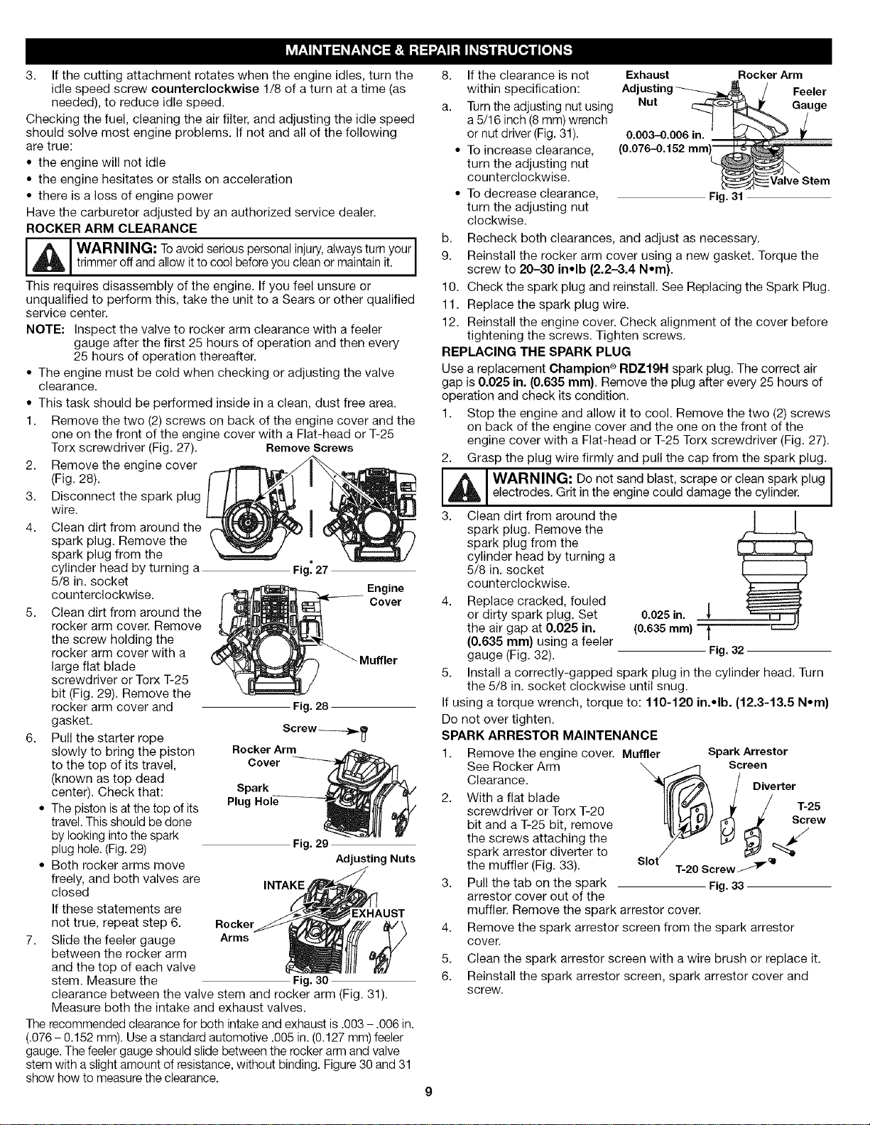
8. If the clearance is not Exhaust Rocker Arm
within specification: Ad Feeler
a. Turn the adjusting nut using Nut Gauge
a 5/16 inch (8 ram) wrench
or nut driver (Fig. 31). 0.003-0.006 in.
• To increase clearance, (0.076-0.152 mm
turn the adjusting nut
counterclockwise.
• To decrease clearance, Fig.31
turn the adjusting nut
clockwise.
b. Recheck both clearances, and adjust as necessary.
9. Reinstall the rocker arm cover using a new gasket. Torque the
screw to 20-30 in•lb (2.2-3.4 N•m).
10. Check the spark plug and reinstall. See Replacing the Spark Plug.
11. Replace the spark plug wire.
12. Reinstall the engine cover. Check alignment of the cover before
tightening the screws. Tighten screws.
REPLACING THE SPARK PLUG
Use a replacement Champion ®RDZ19N spark plug. The correct air
gap is 0.025 in. (0.635 ram). Remove the plug after every 25 hours of
operation and check its condition.
1. Stop the engine and allow it to cool. Remove the two (2) screws
on back of the engine cover and the one on the front of the
engine cover with a Flat-head or T-25 Torx screwdriver (Fig. 27).
2. Grasp the plug wire firmly and pull the cap from the spark plug.
_ I WARNING: Do not sand blast, scrape or clean spark plug I
electrodes. Grit in the engine could damage the cylinder.
3. Clean dirt from around the J J
spark plug. Remove the
spark plug from the
cylinder head by turning a
5/8 in. socket
counterclockwise. ._
4. Replace cracked, fouled
or dirty spark plug. Set 0.025 in.
the air gap at 0.025 in. (0.635ram)
(0.635 mm) using a feeler
gauge (Fig. 32). Fig.32
5. Install a correctly-gapped spark plug in the cylinder head. Turn
the 5/8 in. socket clockwise until snug.
If using a torque wrench, torque to: 110-120 in.•lb. (12.3-13.5 N•m}
Do not over tighten.
SPARK ARRESTOR MAINTENANCE
1. Remove the engine cover. Muffler Spark Arrestor
See Rocker Arm
Clearance.
2. With a flat blade
screwdriver or Torx T-20
bit and a T-25 bit, remove
the screws attaching the
spark arrestor diverter to
the muffler (Fig. 33).
3. Pull the tab on the spark
arrestor cover out of the
Screen
Diverter
/ T-25
Sl°t_crew_ "+
Fig.33
muffler. Remove the spark arrestor cover.
4. Remove the spark arrestor screen from the spark arrestor
cover.
5. Clean the spark arrestor screen with a wire brush or replace it.
6. Reinstall the spark arrestor screen, spark arrestor cover and
screw.
Loading ...
Loading ...
Loading ...