Loading ...
Loading ...
Loading ...
INSTALL HOLDING CLIPS
Install holding clips using one clip for each
three lineal feet of baseboard. Insert clips in air
slots of panel in line with wood studs whose
locations were marked on paper seal. Place
beveled end of clip toward wall and position clip
so it sets squarely in panel (Fig. 14). Use long
wood screw supplied with clip and screw into
stud. Turn screw to point where approximately
1/8” is left. This enables panel to be moved
slightly when making connections.
Be sure to tighten valve and elbow connections.
INSTALL END COVERS ON METAL TRIM
End covers are used to close the exposed ends
of metal trim pieces used. (Note: end covers
are marked for right and left-hand and are not
interchangeable.) Fasten end cover to top and
bottom of trim piece with self-tapping screws
(Fig. 15). When used with trim piece which
does not have holes punched for end cover,
drill 5/32” holes in trim piece using end cover as
template.
INSTALL WALL CLIPS, VALVE AND PLAIN
ENCLOSURES
Wall clips are used to hold trim securely in
place. Set the valve and plain enclosures to be
used in position on baseboard. Mark a line on
the wall using the top rear edge of the trim
piece against the wall as a guide (Fig. 16).
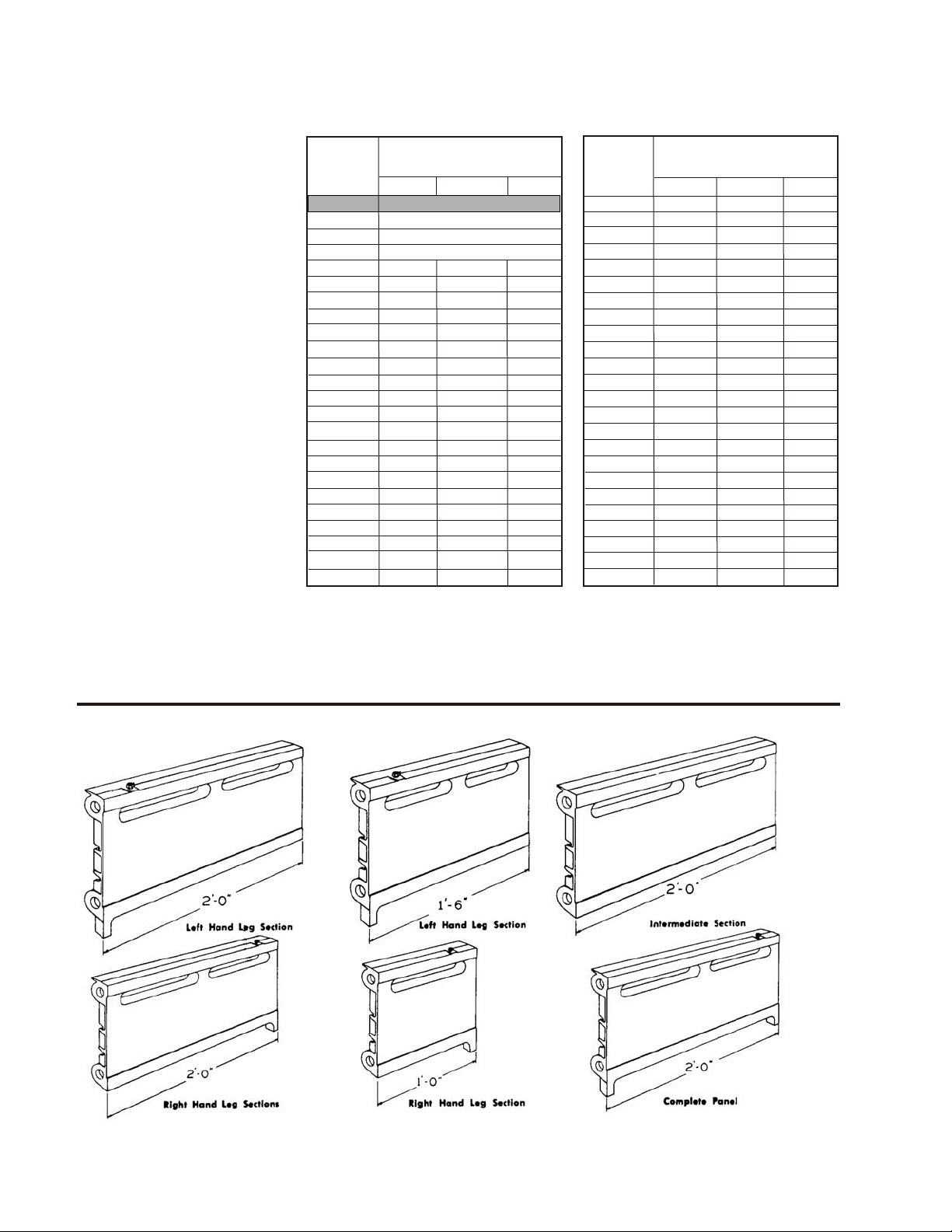
Weil-McLain Cast Iron
Baseboard panels are shipped
assembled, ready to install in
lengths of 6’ or less. All longer
panels are shipped in two or
more assemblies. All panels
from 6-1/2’ to12’ lengths are
shipped in two assemblies,
panels 12-1/2’ to 18’ in length in
three assemblies, and panels
from 18-1/2’ to 24’ lengths in
four assemblies.
All 5-1/2’ left sub-assemblies
consist of one 1-1/2’ left-hand
leg section and two 2’ interme-
diate sections. All 6’ left sub-
assemblies consist of one 2’
left-hand leg section and two 2’
intermediate sections. All 6’
center sub-assemblies consist
of three 2’ intermediate sec-
tions. Right sub-assemblies
consist of either a 2’ or 1’ right-
hand leg section and the
required number of 2’ intermedi-
ate sections.
ASSEMBLY TABLE - CIBB PANELS
Remove trim. Install clip with top approximately 1/8”
below line. If wall is plaster, cover area where clip
screw is installed with tape to prevent plaster from
chipping. Clip should be set near end of trim away
from baseboard panel (Fig. 17). Install one clip for
each valve or plain enclosure. When metal
extension is used, install one clip for each two lineal
feet. (For matched metal extension, see instructions
on page 6 - “INSTALL METAL EXTENSION AND
SPLICE PIECE.”) Valve and plain enclosure are set
in place overlapping the end of panel by 1/2.” Trim
overlaps over rear edge of baseboard. Fasten trim
to leg of panel with self-tapping screw furnished.
If distance from end of panel is between 5” to 9-5/8”
and access is not needed, use extended plain
enclosure and cut to necessary dimension.
INSTALL INSIDE AND OUTSIDE CORNERS
Corners are set in place overlapping the ends of the
baseboard panels approximately ½.” They are
designed to catch behind the panels at the top edge.
Attach the corners to the panel legs with the self-
tapping screws (Fig. 18). Extended inside corners
can be used to cover connections up to 9-5/8” from
the face of the wall. Cut extended corner to desired
dimension. Drill a 5/32” hole 1/4” from the end of
corner and 1” up from the bottom. Install corner
cover and attach to baseboard.
Install holding clip
Mark line on wall for top of trim
Attach end cover to enclosure
Install wall clip
Attach corner to panel legs
Fig. 16
Fig. 17
Fig. 18
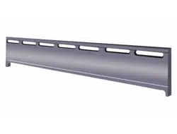
CIBB BASEBOARD PANELS
Fig. 14
Fig. 15
Base-Base-
BoardBoard
LengthsLeftCenterRightLengthsLeftCenterRight
12-1/2 ft.5-1/2 ft.6 ft.1 ft.
1 ft.13 ft.6 ft.6 ft.1 ft.
1-1/2 ft.13-1/2 ft.5-1/2 ft.6 ft.2 ft.
2 ft.14 ft.6 ft.6 ft.2 ft.
2-1/2 ft.1-1/2 ft.1 ft.14-1/2 ft.5-1/2 ft.6 ft.3 ft.
3 ft.2 ft.1 ft.15 ft.6 ft.6 ft.3 ft.
3-1/2 ft.1-1/2 ft.2 ft.15-1/2 ft.5-1/2 ft.6 ft.4 ft.
4 ft.2 ft.2 ft.16 ft.6 ft.6 ft.4 ft.
4-1/2 ft.1-1/2 ft.2 ft.1 ft.16-1/2 ft.5-1/2 ft.6 ft.5 ft.
5 ft.2 ft.2 ft.1 ft.17 ft.6 ft.6 ft.5 ft.
5-1/2 ft.1-1/2 ft.2 ft.2 ft.17-1/2 ft.5-1/2 ft.6 ft.6 ft.
6 ft.2 ft.2 ft.2 ft.18 ft.6 ft.6 ft.6 ft.
6-1/2 ft.5-1/2 ft.1 ft.18-1/2 ft.5-1/2 ft.2 - 6 ft.1 ft.
7 ft.6 ft.1 ft.19 ft.6 ft.2 - 6 ft.1 ft.
7-1/2 ft.5-1/2 ft.2 ft.19-1/2 ft.5-1/2 ft.2 - 6 ft.2 ft.
8 ft.6 ft.2 ft.20 ft.6 ft.2 - 6 ft.2 ft.
8-1/2 ft.5-1/2 ft.3 ft.20-1/2 ft.5-1/2 ft.2 - 6 ft.3 ft.
9 ft.6 ft.3 ft.21 ft.6 ft.2 - 6 ft.3 ft.
9-1/2 ft.5-1/2 ft.4 ft.21-1/2 ft.5-1/ ft.2 - 6 ft.4 ft.
10 ft.6 ft.4 ft.22 ft.6 ft.2 - 6 ft.4 ft.
10-1/2 ft.5-1/2 ft.5 ft.22-1/2 ft.5-1/2 ft.2 - 6 ft.5 ft.
11 ft.6 ft.5 ft.23 ft.6 ft.2 - 6 ft.5 ft.
11-1/2 ft.5-1/2 ft.6 ft.23-1/2 ft.5-1/2 ft.2 - 6 ft.6 ft.
12 ft.6 ft.6 ft.24 ft.6 ft.2 - 6 ft.6 ft.
complete assembly
Sub-AssembliesSub-Assemblies
complete assembly
complete assembly
NOTE: 1’ thru 6’ complete assemblies are shipped assembled.
Part No. 550-110-455 0707
4
5
Part No. 550-110-455 0707
Loading ...
Loading ...