Loading ...
Loading ...
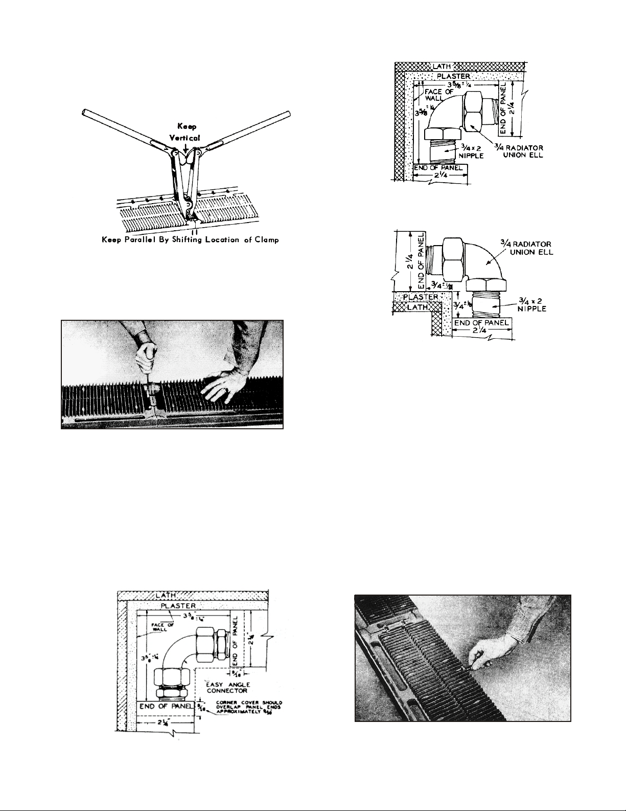
Note following precautions (Fig. 8):
a. Keep clamp vertical.
b. Keep ends of sections parallel.
c. Apply steady pressure.
When sections are drawn up, remove clamp and
place 5/16” tie bolts in place. Tighten with open-end
wrench for 5/16” hex nut (Fig. 9). Make sure
sections are assembled perfectly straight, are in
perfect alignment and are not bowed.
For corner connections using copper connections,
install and tighten adapter or compression fittings
(Fig. 10). For cast iron corner connections, install
and tighten straight piece of union radiator valves
and elbows (Fig. 11 & 12). Plug unused openings
with 3/4” plug (furnished). Check plug to make sure
connection is tight.
EASY ANGLE COPPER CONNECTION
INSTALLING CENTER LEG SUPPORTS
Screw 3/8” x 1-1/2” leg support screws furnished in
selected support lugs on bottom of intermediate
section (Fig. 13). Table below gives required
number of screws based on panel length. Space
support screws evenly.
Panel length No. of supports
6’ - 14’1
15’ - 21’2
22’ - 30’3
Stand panel in position against wall. The legs at the
end of the panels should rest on the finished floor or
wood elevating blocks or strips. Adjust support
screws to bear on floor and give equal distribution of
weight over entire panel length.
INSTALL AIR SEAL
Place air seal the length of the panel plus 1” overlap.
The seal should be installed securely and smoothly
in place with tacks (Fig. 4 & 5). If baseboard is to be
set before finished floor is in place, air seal should
extend to rough floor. Mark location of the studs on
the front of the air seal. These marks will be used to
position the holding clips after the panel is in
position. It is recommended that a wood molding be
used at the finished floor line to hold the air seal
snugly to the wall.
CAST IRON BASEBOARD PANEL ASSEMBLY
Be sure to remove protective plugs from
nipple ports and tappings before assembling panel.
1. Line up two sections on the floor with fins up
(Fig. 6).
Tacking paper seal in place
Fig. 5
Cross-section of end elevation
2. Remove protective plugs from the nipple
ports and tappings.
3. Clean the edges and push nipple ports on
the sections.
4. Wipe push nipples clean.
5. Apply thin coating of graphite paste or pipe
joint compound to the external surfaces of
the nipples.
6. Insert push nipples into one section, square
them, and tap them firmly into place with a
rawhide or wooden mallet.
7. Fit the second panel to the nipples.
8. Place the jaws of the clamp in the two
recesses between the push nipple hubs
and pull together (Fig. 7).
Fig. 6
Fig. 7
Fig. 8
Fig. 12
Fig. 11
Fig. 10
Tightening 5/16” hex nuts on tie bolts
after sections have been drawn up
Plan view of inside corner hookup
Plan view of outside corner hookup
Screw center leg support in baseboard
CAST IRON CONNECTIONS
Fig. 13
Fig. 9
Fig. 4
Part No. 550-110-455 0707
2
3
Part No. 550-110-455 0707
CAUTION
Loading ...
Loading ...
Loading ...