
/;RnFrXMnN°
MODEL NUMBER 917.258542 OWNER'SMANUAL
o Assembly
Operation
Customer Responsibilities
Service and Adjustments
®Repair Parts
CAUTION: Read and follow all safety rules and instructions before operating this equipment.
FOR CONSUMER ASSISTANCE HOT LINE, CALL THIS TOLL FREE NUMBER: 1-800-659-5917
.................................... I1' III II
_ - I1"11I IIIIIIIH
SAFETY RULES
Safe Operation Practices for Ride-On Mowers
IMPORTANT: THiS CUTTING MACHINE iS CAPABLE OF AMPUTATING HANDS AND FEETAND THROWING OBJECTS
FAILURE TO OBSERVE THE FOLLOWING SAFETY INSTRUCTIONS COULD RESULT iN SERIOUS INJURY OR DEATH
!. GENERAL OPERATION
• Read, understand, and follow all instructions in the manual
and on the machine before starting
. Only allow responsible adults, who are familiar with the
instructions, to operate the machine_
• Clear the area of objects such as rocks, toys, wire, etc,
which could be picked up and thrown by the blade.
• Be sure the area is clearof other people before mowing Stop
machine if anyone enters the area.
• Never carry passengers
• Do not mow in reverse unless absolutely necessary Always
look down and behind before and while backing,.
• Be aware of the mower discharge direction and do not point
it at anyone. Do not operate the mower without either the
entire grass catcher or the guard in place,
• Slow down before turning
• Never leave a running machine unattended Nways turn off
blades, set parking brake, stop engine, and remove keys
before dismounting.,
• Turn off blades when not mowing
• Stop engine before removing grass catcher or unclogging
chute.,
• Mow only in daylight or good artificial light.
° Do not operate the machine while under the influence of
alcohol or drugs
• Watch for traffic when operating near or crossing roadways,
• Use extra care when loading or unloading the machine into
a trailer or truck.
II. SLOPE OPERATION
Slopes are a major factor related to loss-of-control and
tipover accidents, which can result in severe injury or deal h..
Ali slopes require extra caution. If you cannot back up the
slope or if you feel uneasy on it, do not mow it,,
DO:
• Mow up and down slopes, not across,
• Remove obstacles such as rocks, tree limbs, etc
• Watch for holes, ruts, or bumps, Uneven terrain could
overturn the machine Tall grass can hide obstacles.
• Use slow speed Choose a low gear so that you will not have
to stop or shift while on the slope.
• Follow the manufacturer's recommendations for wheel
weights or counterweights to improve stability.
• Use extra care with grass catchers or other attachments.
These can change the stability of the machine
• Keep all movement on the slopes slow and gradual Do not
make sudden changes in speed or direction,
• Avoid starting or stopping on a slope, If tires lose traction,
disengage the blades and proceed slowly straight down the
slope.
DO NOT,
• Donor turn on slopes unless necessary, and then, turn slowly
and gradually downhill, if possible
• Do not mow near drop-offs, ditches, or emb&nkments The
mower could suddenly turn over if a wheel is over the edge
of a cliff or ditch, or if an edge caves in
• Do not mow on wet grass Reduced traction could cause
sliding
. Do not try to stabilize the machine by putting your foot on the
ground
. Do not use grass catcher on steep slopes
III. CHILDREN
Tragic accidents can occur if the operator is not alert to the
presence of children, Children are often attracted to the
machine and the mowing activity Never assume that
children will remain where you last saw them°
• Keep children out of the mowing area and under the watchful
care of another responsible adult
,, Be alert and turn machine off if children enter the area
° Before and when backing, look behind and down for small
children
• Never carry children They may fall off and be seriously
injured or interfere with safe machine operation
• Never allow children to operate the machine
,' Use extra care when approaching blind corners, shrubs.
trees, or other objects that may obscure vision
IV. SERVICE
• Use extra care in handling gasoline and other fuels They are
flammable and vapors are explosive,
Use only an approved container
Never remove gas cap or add fuel with the engine
running. Allow engine to cool before refueling Do not
smoke
Never refuel the machine indoors
Never store the machine or fuel container inside where
there is an open flame, such as a water heater
• Never run a machine inside a closed area
• Keep nuts and bolts, especially blade attachment bolts, tight
and keep equipment in good condition,
- Never tamper with safety devices. Check their proper
operation regularly
• Keep machine free of grass, Ieaves, or other debris build-up.
Clean oil or fuel spillage Allow machine to cooI before
storing.
• Stop and inspect the equipment if you strike an object
Repair, if necessary, before restarting
• Never make adjustments or repairs with the engine running
• Grass catcher components are subject to wear, damage, and
deterioration, which could expose moving parts or allow
objects to be thrown. Frequently check components and
replace with manufacturer's recommended parts, when nec-
essary.,
° Mower blades are sharp and can cut Wrap lhe blade(s) or
wear gloves, and use extra caution when servicing them
• Check brake operation frequently Adjust and service as
required,
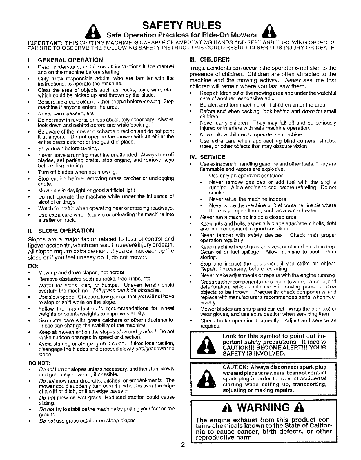
&
i i
Look for this symbol to point out !m-
pedant safety precautions, it means
CAUTION!!! BECOMEALERT!t! YOUR
SAFETY IS INVOLVED.
CAUTION: Always disconnect spark plug
wire and place wire where it cannot contact
spark plug in order to prevent accidental
starting when setting up, transporting,
adjusting or making repairs°
A WARNING A
The engine exhaust from this product con-
tains chemicals known to the State of Califor-
nia to cause cancer, birth defects, or other
reproductive harm.
ii ii i ii iii iiiiii1,1

CONGRATULATIONS on your purchase of a Sears
Tractor, it has been designed, engineered and manufac-
tured to give you the best possible dependability and
performance.,
Should you experience any problem you cannot easily
remedy, please contact your nearest Sears Authorized
Service Center/DepartmenL We have competent, well-
trained technicians and the proper tools to service or repair
this tractor.
Please read and retain this manual. The instructions wil!
enable you to assemble and maintain your tractor properly.,
Always observe the "SAFETY RULES",
VlODEL
NUMBER 917,258542
SERIAL
NUMBER
DATEOFPURCHASE
THE MODELAND SERIAL NUMBERSWILLBE FOUND
ON A PLATE UNDER THE SEAT°
YOU SHOULD RECORD BOTH SERIAL NUMBER AND
DATE OF PURCHASE AND KEEP IN A SAFE PLACE
FOR FUTURE REFERENCE°
MAINTENANCE AGREEMENT
A Sears Maintenance Agreement is available on this prod-
ucto Contact your nearest Sears store for details.
CUSTOMER RESPONSIBILITIES
- Read and observe the safety rules.
o Fo!low a regular schedule in maintaining, caring for and
using your tractor
= Follow the instructions under "Customer Responsibili-
ties" and "Storage" sections of this owner's manual
PRODUCT SPECIFICATIONS
HORSEPOWER: 15.0
GASOLINE CAPACITY 1 25 GALLONS
AND TYPE: UNLEADED REGULAR
OIL TYPE (API-SF/SG/SH): SAE 10W30 (above 32°F)
SAE 5W-30 (below 32°F)
OIL CAPACITY: W/FILTER: 4.0 PINTS
W/O FILTER: 3.5 PINTS
SPARK PLUG: CHAMPION RC12YC
(GAP: .040")
VALVE CLEARANCE: NOT ADJUSTABLE
GROUND SPEED (MPH): FORWARD:
1st 1.1
2nd ! 5
3rd 23
4th 3.5
5th 4-4
6th 5 7
REVERSE: t ,7
TIRE PRESSURE: FRONT: 14 PSI
REAR: 10 PSI
CHARGING SYSTEM: 3 AMPS BATTERY
5 AMPS HEADLIGHTS
BATTERY: AMP/HR: 30
MIN, CCA: 240
CASE SIZE: UtR
BLADE BOLT TORQUE: 30-35 FT LBS
WARNING: This tractor is equipped with an internal
combustion engine and should not be used on or near any
unimproved forest-covered, brush-covered or grass-cov*
ered land unless the engine's exhaust system is equipped
with a spark arrester meeting applicable local or state laws
(if any). If a spark arrester is used, it should be maintained
in effective working order by the operator.
In the state of California the above is required by law
(Section 4442 of the California Public Resources Code).
Other states may have similar laws,. Federal laws apply on
federal lands. A spark arrester for the muffler is available
through your nearest Sears Authorized Service Center/
Department (See REPAIR PARTS section of this manual).
ii lU,,i , ,i .......................
LIMITED TWO YEAR WARRANTY ON CRAFTSMAN RIDING EQUIPMENT
For two (2) years from the date of purchase, if this Craftsman Riding Equipment is maintained, lubricated and tuned up according to
the instructions in the owner's manual, Sears will repair or replace, free of charge, any parts found to be defective in material or
workmanship.
This Warranty does not cover:.
• Expendable items which become worn during normal use, such as blades, spark plugs, air cleaners, belts, etc.
• Tire replacement or repair caused by punctures from outside objects, such as nails, thorns, stumps, or glass.
• Repairs necessary because of operator abuse, negligence, improper storage or accident or the failure to maintain the
equipment according to the instructions contained in the owner's manual.
• Riding equipment used for commercial or rental purposes,
LIMITED 90 DAY WARRANTY ON BATTERY
For ninety (90) days from date of purchase, if any battery included with this riding equipment proves defective in material or
workmanship and our testing determines the battery will not hold a charge, Sears will replace the battery at no charge.
IN-HOME WARRANTY SERVICE ON YOUR CRAFTSMAN RIDING EQUIPMENT IS AVAILABLE AT NO-CHARGE FOR 30 DAYS
FROM THE DATE OF PURCHASE. PLEASE CONTACT YOUR NEAREST SERVICE CENTER. AFTER 30 DAYS FROM THE
DATE OF PURCHASE, WARRANTY SERVICE IS AVAILABLE BY TAKING YOUR CRAFTSMAN RIDING EQUIPMENT TO YOUR
NEAREST SEARS SERVICE CENTER. (IN-HOME WARRANTY SERVICE WILL STILL BE AVAILABLE AFTER 30 DAYS FROM
THE DATE OF PURCHASE BUT A STANDARD TRIP CHARGE WILL APPLY.) THIS WARRANTY APPLIES ONLY WHILE THIS
PRODUCT IS IN THE UNITED STATES.
This Warranty gives you specific legal rights, and you may also have other rights which may vary from state to state
SEARS, ROEBUCK AND CO.., D/817 WA, HOFFMAN ESTATES, IL 60179
.... i .... ........................ iii....... ,...... ,, inl'
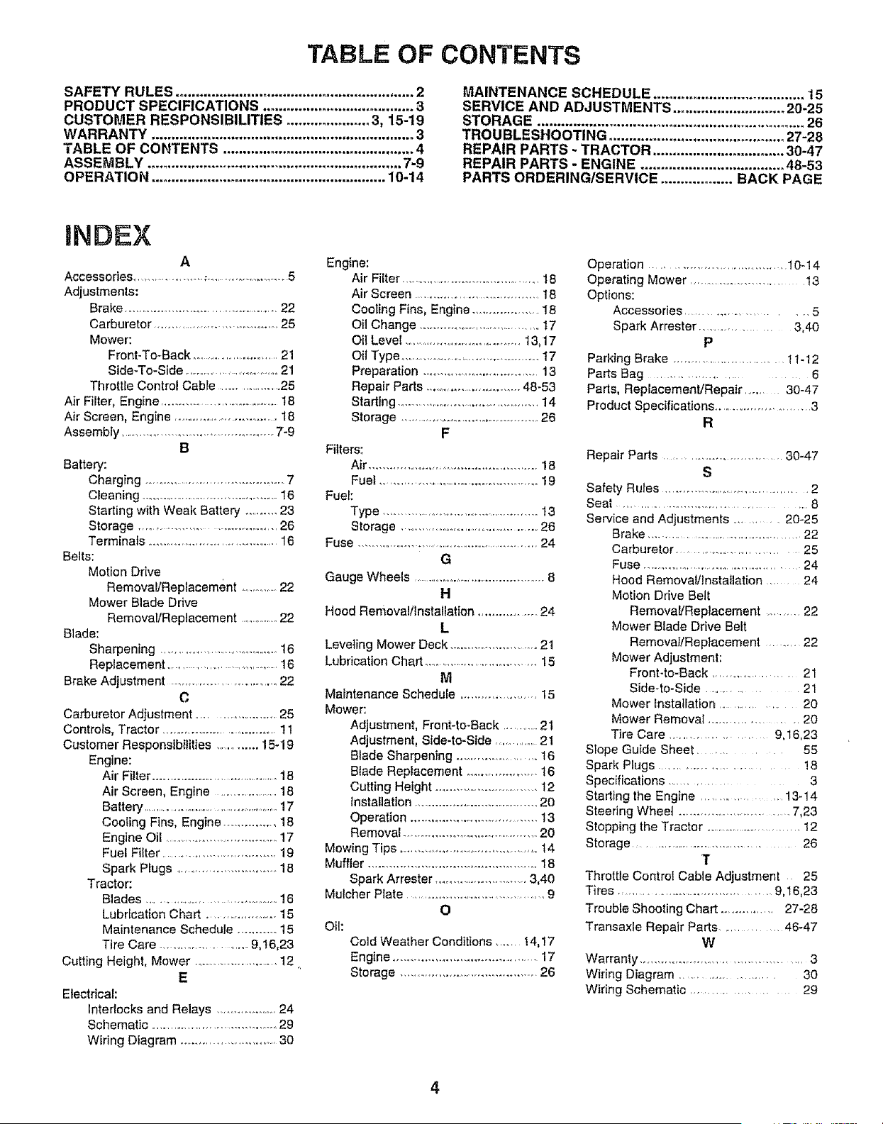
TABLE OF CONTENTS
SAFETY RULES ............................................................ 2
PRODUCT SPECIFICATIONS ...................................... 3
CUSTOMER RESPONSIBILITIES ..................... 3, 15-19
WARRANTY .................................................................. 3
TABLE OF CONTENTS ................................................ 4
ASSEMBLY ................................................................ 7-9
OPERATION ........................................................... 10-14
MAINTENANCE SCHEDULE ...................................... 15
SERVICE AND ADJUSTMENTS ............................ 20-25
STORAGE ................................................................... 26
TROUBLESHOOTING ............................................ 27-28
REPAIR PARTS - TRACTOR ................................. 30-47
REPAIR PARTS - ENGINE .................................... 48-53
PARTS ORDERING/SERVICE .................. BACK PAGE
INDEX
A
Accessories .... ................ _ ........................ 5
Adjustments:
Brake ............................................. 22
Carburetor .................................... 25
Mower:
Front-To-Back .............................21
Side-To-Side ...............................21
Throttle Control Cable .......................25
Air Filter, Engine ................................... 18
Air Screen, Engine ................................ t8
Assembly .............................................. 7-9
B
Battery:
Charging ........................................... 7
Cleaning ......................................... 16
Starting with Weak Battery .......... 23
Storage .................................. 26
Terminals ..............................................16
Belts:
Motion Drive
Removal/Replacement ...............22
Mower Blade Drive
Removal/Replacement ................22
Blade:
Sharpening .......................................16
Replacement ..........................................16
Brake Adjustment ............................. 22
C
Carburetor Adjustment ......................... 25
Controls, Tractor ................................ 11
Customer Responsibilities ............. 15-19
Engine:
Air Filter ..............................................18
Air Screen, Engine ....................18
Battery ..................................................17
Cooling Fins, Engine ............... 18
Engine Oil .................................. 17
Fuel Filter .................................. 19
Spark Plugs .............................. 18
Tractor:
Blades .................................... 16
Lubrication Chart ..................... 15
Maintenance Schedule ........... 15
Tire Care ........................ 9,16,23
Cutting Height, Mower ........................ 12
E
Electrical:
interlocks and Relays ................... 24
Schematic .................................... .... 29
Wiring Diagram .............................. 30
Engine:
Air Filter .......................................... 18
Air Screen ...................................... 18
Cooling Fins, Engine ................... 18
Oil Change .................................. 17
Oit Level ........................................t3,17
Oil Type ..................................................17
Preparation ..................................... 13
Repair Parts .............................. 48-53
Starting ...............................................14
Storage .............................................26
F
Filters:
Air ................................................. 18
Fuel ................................................ 19
Fuel:
Type .............................................. 13
Storage ........................................... 26
Fuse ............................................................ 24
G
Gauge Wheels ......................................... 8
H
Hood Removal/Installation ................. 24
L
Leveling Mower Deck ......................... 21
Lubrication Chart .......................................15
M
Maintenance Schedule ....................... 15
Mower:
Adjustment, Front-to-Back .............21
Adjustment, Side-to-Side ...............21
Blade Sharpening ....................... 16
Blade Replacement ...................... 16
Cutting Height .............................. 12
Installation ...................................... 20
Operation .................................... 13
Removal ...................................... 20
Mowing Tips ......................................... 14
Muffler .................................................. 18
Spark Arrester ........................... 3,40
Mulcher Plate ........................................... 9
O
Oil:
Cold Weather Conditions ........ 14,17
Engine ......................................... 17
Storage ....................................... 26
Operation ........................................ 10-14
Operating Mower ........................... 13
Options:
Accessories ........................ 5
Spark Arrester .................. 3,40
P
Parking Brake ................................. 11-12
Parts Bag .............................. 6
Parts, Replacement/Repair ......... 30-47
Product Specifications ........................... 3
R
Repair Parts ............................ 30-47
S
Safety Rules ....................................... 2
Seat .............................................. 8
Service and Adjustments ........... 20-25
Brake .............................................. 22
Carburetor .................................... 25
Fuse .............................................. 24
Hood Removal/Installation ..... 24
Motion Drive Belt
Removal/Replacement ............22
Mower Blade Drive Belt
Remova!/Replacement ......... 22
Mower Adjustment:
Front4o-Back ....................... 21
Side-to-Side ..................... 21
Mower installation ........................ 20
Mower Removal .................... 20
Tire Care .................. 9,16,23
Slope Guide Sheet ................... 55
Spark Plugs ................................. 18
Specifications ........................... 3
Starting the Engine ..................... 13-14
Steering Wheet .............................. 7,23
Stopping the Tractor .................................12
Storage ....................................... 26
T
Throttle Control Cable Adjustment 25
Tires ....................................... 9,16,23
Trouble Shooting Chart ................ 27-28
Transaxle Repair Parts ........... 46-47
W
Warranty ............................................. 3
Wiring Diagram .............................. 30
Wiring Schematic ............................. 29
4
=
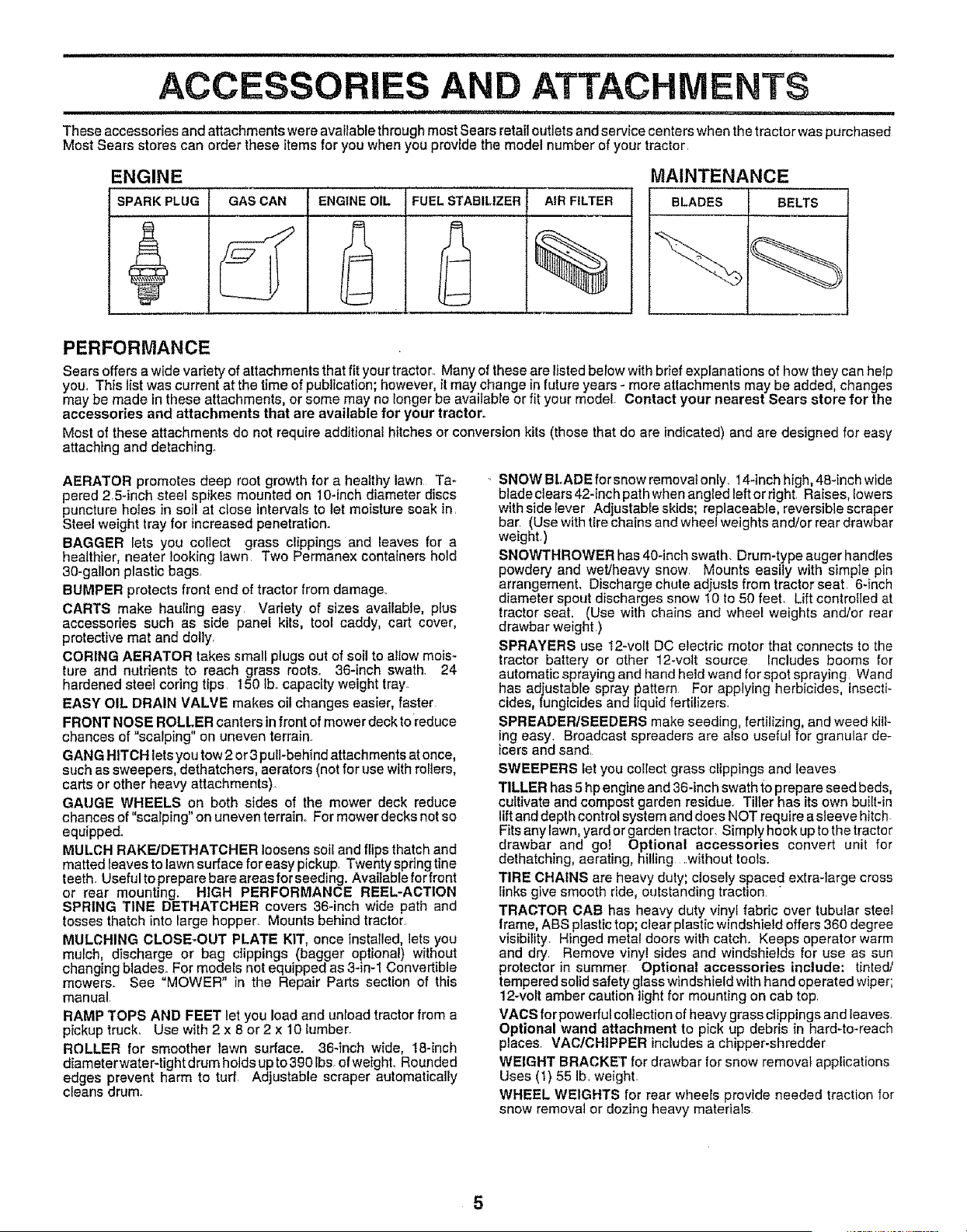
AND ATTACHMENTS
These accessories and attachments were available through most Sears retail outlets and service centers when the tractor was purchased
Most Sears stores can order these items for you when you provide the model number of your tractor.
MAINTENANCE
BLADES BELTS j
ENGINE
SPARK PLUG GAS CAN ENGINE OIL FUEL STABILIZER AIR FILTER
%
PERFORMANCE
Sears offers a wide variety of attachments that fit your tractor.. Many of these are listed below with brief explanations of how they can help
you_ This list was current at the time of publication; however, it may change in future years - more atlachments may be added, changes
may be made in these attachments, or some may no longer be available or fit your model. Contact your nearest Sears store for the
accessories and attachments that are available for your tractor°
Most of these attachments de not require additional hitches or conversion kits (those that do are indicated) and are designed for easy
attaching and detaching_
AERATOR promotes deep root growth for a healthy lawn Ta_
pered 2.5-inch steel spikes mounted on 10-inch diameter discs
puncture hotes in soil at close intervals to let moisture soak in.
Steel weight tray for increased penetration.
BAGGER lets you collect grass clippings and leaves for a
healthier, heater looking lawn. Two Perrnanex containers hold
30-gal!on plastic bags.
BUMPER protects front end of tractor from damage..
CARTS make hauling easy Variety of sizes available, plus
accessories such as side panei kits, tool caddy, cart cover,
protective mat and dolly.
CORING AERATOR takes small plugs out of soi! to allow mois-
ture and nutrients to reach grass roots. 36-inch swath 24
hardened steet coring tips 150 Ib..capacity weight tray.
EASY OIL DRAIN VALVE makes oil changes easier, faster
FRONT NOSE ROLLER canters in front of mower deck toreduce
chances of "scalping" on uneven terrain.
GANG HITCH lets you tow 2 or 3 pull-behind attachments at once,
such as sweepers, dethatchers, aerators (not for use with rollers,
carts or other heavy attachments).
GAUGE WHEELS on both sides of the mower deck reduce
chances of "scalping" on uneven terrain.. For mowerdecksnot so
equipped_
MULCH RAKE/DETHATOHER loosens soil and flips thatch and
matted leaves to lawn su[face for easy pickup. Twenty spring tine
teeth. Useful to prepare bare areas for seeding. Available forfront
or rear mounting. HIGH PERFORMANCE REEL-ACTION
SPRING TINE DETHATCHER covers 36-inch wide path and
tosses thatch into large hopper. Mounts behind tractor
MULCHING CLOSE-OUT PLATE KIT, once installed, lets you
mulch, discharge or bag clippings (bagger optional) without
changing blades. For models not equipped as 3-in-1 Convertible
mowers. See "MOWER" in the Repair Parts section of this
manuat_
RAMP TOPS AND FEET let you load and unload tractor from a
pickup truck. Use with 2 x 8 or2 x 10 lumber.
ROLLER for smoother fawn surface. 36-inch wide, 18-inch
diameterwater-tight drum holds up to 390 lbs. of weight. Rounded
edges prevent harm to turf. Adjustable scraper automatically
deans drum.
SNOW BLADE for snow removat only. 14-inch high, 48-inch wide
blade clears 42-inch path when angled left or right. Raises, lowers
with side Iever Adjustable skids; replaceable, reversible scraper
bar. (Use with tire chains and wheel weights and/or rear drawbar
weight.)
SNOWTHROWER has 40-inch swath. Drum-type auger handtes
powdery and wet/heavy snow. Mounts easily with simple pin
arrangement. Discharge chute adjusts from tractor seat 6-inch
diameter spout discharges snow 10 to 50 feet. Lift controlled at
tractor seat. (Use with chains and wheel weights and/or rear
drawbar weight.)
SPRAYERS use 12-volt DC electric motor that connects to the
tractor battery or other 12-vott source _ncludes booms for
automatic spraying and hand held wand for spot spraying Wand
has adjustable spray I:_attern For applying herbicides, insecti-
cides, fungicides and liquid fertilizers.
SPREADER/SEEDERS make seeding, fertilizing, and weed kill-
ing easy. Broadcast spreaders are also useful for granular de-
icers and sand.
SWEEPERS let you collect grass clippings and leaves
TILLER has 5 hp engine and 36-inch swath to prepare seed beds,
cultivate and compost garden residue. Tiller has its own built-in
lift and depth control system and does NOT require a sleeve hitch.
Fits any lawn, yard or garden tractor. Simply hook up to the tractor
drawbar and go! Optional accessories convert unit for
dethatching, aerating, hilling _.without tools.
TIRE CHAINS are heavy duty; closely spaced extra-large cross
links give smooth ride, outstanding traction. "
TRACTOR CAB has heavy duty vinyl fabric over tubular steel
frame, ABS plastic top; clear plastic windshield offers 360 degree
visibility Hinged metal doors with catch. Keeps operator warm
and dry. Remove vinyl sides and windshields for use as sun
protector in summer Optional accessories include: tinted/
tempered solid safety glass windshield with hand operated wiper;
12-voft amber caution light for mounting on cab top.
VAGS for powerful collection of heavy grass clippings and leaves.
Optional wand attachment to pick up debris in hard-to-reach
places. VAC/CHtPPER includes a chipper-shredder
WEIGHT BRACKET for drawbar for snow removal applications
Uses (1) 55 Ib. weighL
WHEEL WEIGHTS for rear wheels provide needed traction for
snow removal or dozing heavy materials
5
,,,i,1,,-,,,. . _ _.._L, ,,,i,,11111 ...... •......... u ii,ul
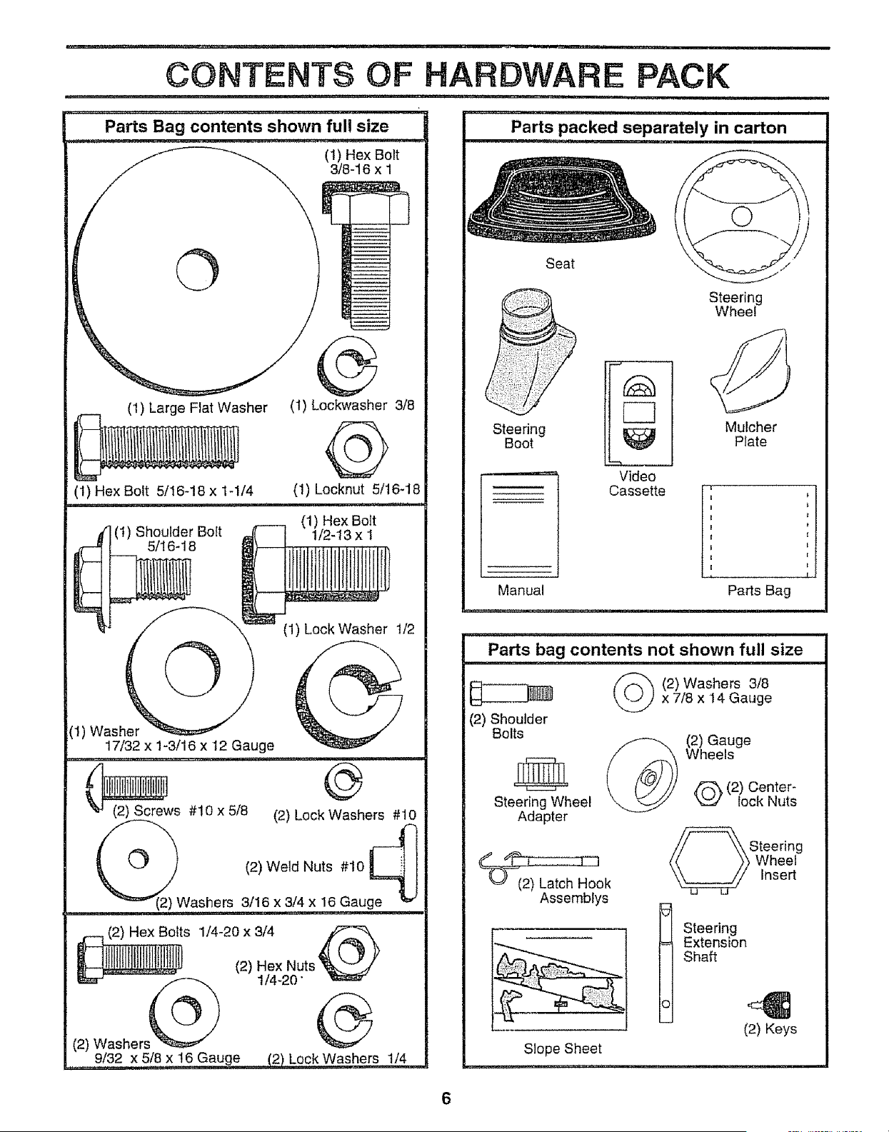
CONTENTS OF HARDWARE PACK
i ,,,U,l,,, ...................... i,,,U,Ul i i , ,
Parts Bag contents shown ful! size
(t) Hex Bolt
3/8-16 x I
©
(1) Large Flat Washer
(1) Hex Bolt 5/16-18 x 1-1/4
d (t) Shoulder Bolt
5/16418
®
(1) Lockwasher 3/8
@
(1) kocknut 5/16-18
i i,nl,,
(1) Hex Bolt
t/2-13 x I
©
(1) Lock Washer 1/2
(1) Washer
17/32 x 1-3/16 x 12 Gauge
u,,,,,,i , ,, ii,
_ws #10 x 5/8 (2) Lock Washers #10
_(2)Washers
(2) Weld Nuts #10 _ l
3/16 x 3/4 x 16 Gauge
O
(2) Washers_
9/32 x 5(8 x 16 Gauge ..... (2) Lock Washers 1/4
Seat
Steering
Boot
Video
Cassette
Manual
Steering
Wheel
Mulcher
Plate
U
Parts Bag
Parts bag contents not shown full size
(2) Washers 3/8
x 7/8 x 14 Gauge
(2) Shoulder
Bolts (2) Gauge
Wheels
_ (2) Center-
Steering Wheel _ lock Nuts
Adapter
) Latch Hook
Assembtys
Steering
Wheel
Insert
I teering
Extension
Shaft
(2) Keys
Slope Sheet
..... r_r,r,_,,,,,,,_,.,.,,,,,,_....
V
!1
' ,i ,ir,,,=H,,
Your new tractor has been assembled at the factory with exception of those parts left unassembled for shipping purposes.
To ensure safe and proper operation of your tractor al! parts and hardware you assemble must be tightened securely. Use
the correct tools as necessary to insure proper tightness.
TOOLS REQUIRED FOR ASSEMBLY
A socket wrench set will make assembly easier, Standard
wrench sizes are listed.
(1) 3/4" Socket w/drive rachet
(2) 7/16" wrenches (1) Phillips Screwdriver
(2) 1/2" wrenches Tire pressure gauge
(1) 9/16" wrench Utility knife
When right or ieft hand is mentioned in this manual, it
means when you are in the operating position (seated
behind the steering wheel),
TO REMOVE TRACTOR FROM CARTON
UNPACK CARTON
• Remove all accessible loose parts and parts cartons
from carton (See page 6),
o Cut, from top to bottom, along lines on all four corners
of carton, and lay panels flat.
• Check for any additional loose parts or cartons and
remove_
BEFORE ROLLING TRACTOR OFF SKID
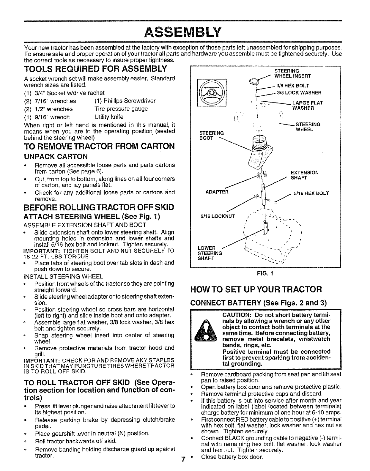
ATTACH STEERING WHEEL (See Fig, 1)
ASSEMBLE EXTENSION SHAFT AND BOOT
• Slide extension shaft onto lower steering shaft° Align
mounting holes in extension and lower shafts and
instalI 5/16 hex bolt and Iocknut. Tighten securely.
IMPORTANT: TIGHTEN BOLT AND NUT SECURELY TO
18-22 FT_ LBS TORQUE°
o Place tabs of steering boot over tab slots in dash and
push down to secure.
INSTALL STEERING WHEEL
• Position front wheels of the tractor so they are pointing
straight forward.
• Slide steering wheel adapter onto steering shaft exten-
sion.
,, Position steering wheel so cross bars are horizontal
(fett to right) and slide inside boot and onto adapter.
, Assemble large flat washer, 3/8 lock washer, 3/8 hex
bolt and tighten securely°
, Snap steering wheel insert into center of steering
wheel.
o Remove protective materials from tractor hood and
grill.
IMPORTANT: CHECK FOR AND REMOVE ANY STAPLES
IN SKID THAT MAY PUNCTURE TIRES WHERE TRACTOR
IS TO ROLL OFF SKID,
TO ROLL TRACTOR OFF SKID (See Opera-
tion section for location and function of con-
trols)
• Press lift lever plunger and raise attachment lift lever to
its highest position.
• Release parking brake by depressing clutch/brake
pedal.
o Place gearshift lever in neutral (N) position.
o Roll tractor backwards off skid,
° Remove banding holding discharge guard up against
tractor
STEERING
[_ WHEEL INSERT
I _ LARGE FLAT
= WASHER
. \\
STEERING
" WHEEL
STEERING
BOOT
ADAPTER
_.,/ 5/16 HEX BOLT
FIG. 1
HOW TO SET UP YOUR TRACTOR
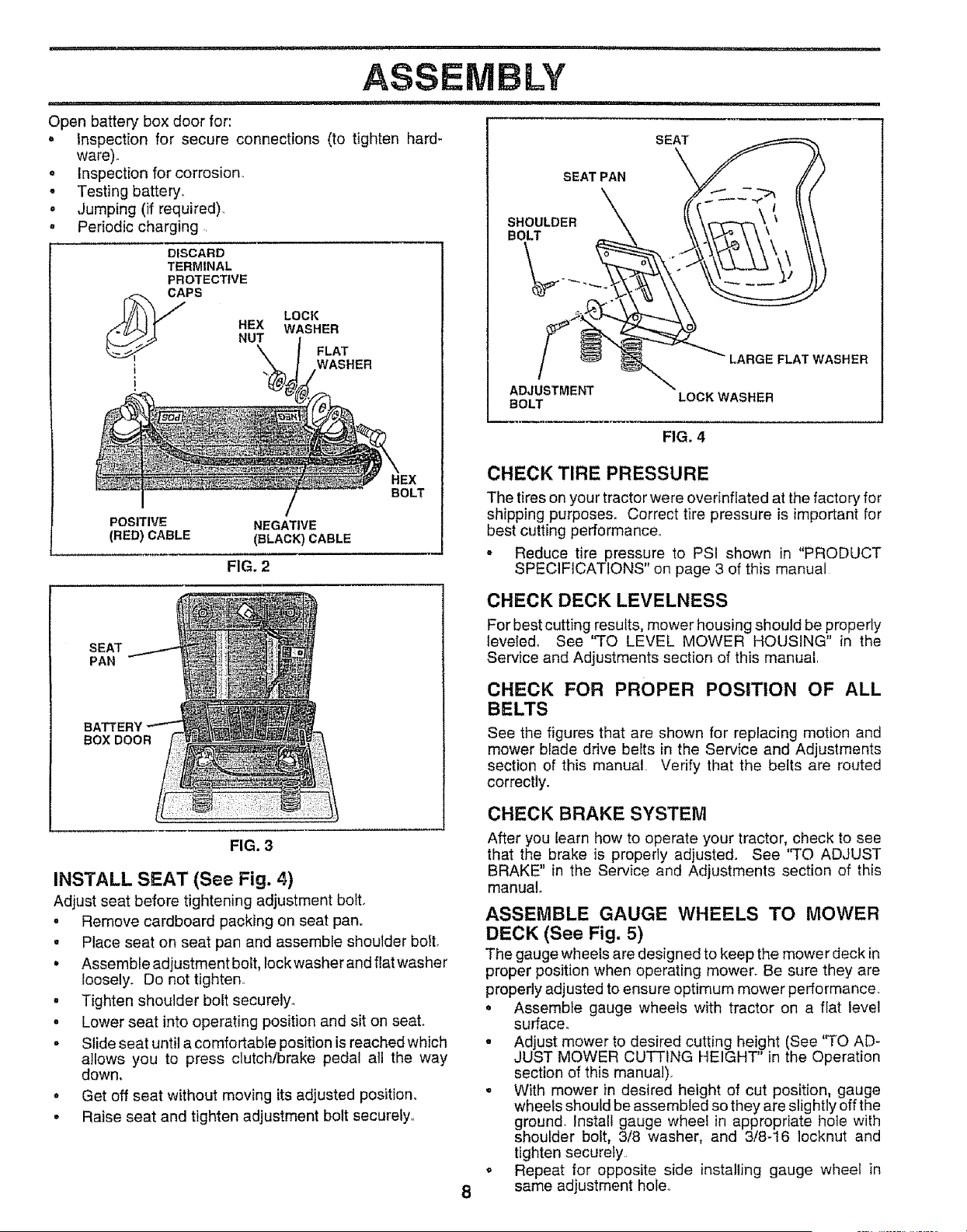
CONNECT BATTERY (See Figs. 2 and 3)
CAUTION: Do not short battery termi-
nals by allowing a wrench or any other
object to contact both terminals at the
sametime. Before connecting battery,
remove metal bracelets, wristwatch
bands, rings, etc.
Positive terminal must be connected
first to prevent sparking from acciden-
tal grounding.
o
Remove cardboard packing from seat pan and lift seat
pan to raised position,
= Open battery box door and remove protective plastic,
• Remove terminal protective caps and discard.
• If this battery is put into service after month and year
indicated on label (label located between terminals)
charge battery for minimum of one hour at 6-10 amps,
• First connect RED battery cabte to positive (+) terminal
with hex bolt, flat washer, fock washer and hex nut as
shown, Tighten securely,
• Connect BLACK grounding cable to negative (-) termi-
nal with remaining hex bolt, flat washer, lock washer
and hex nut. Tighten securely.
Close battery box door.
inspectionfor secureconnections(to tightenhard-
LOCK
WASHER
FLAT
MASHER
ware)°
o Inspection for corrosion.
o Testing battery°
. ,Jumping (if required).
o Periodic charging.
SEAT
PAN
BOX DOOR
DISCARD
TERMINAL
PROTEC_VE
CAPS
U HEX
NUT
POSITIVE NEGATIVE
(RED) CABLE (BLACK) CABLE
FIG. 2
FIG. 3
INSTALL SEAT (See Fig. 4)
Adjust seat before tightening adjustment boft,
. Remove cardboard packing on seat pan°
HEX
BOLT
= Place seat on seat pan and assemble shoulder boil
• Assemble adjustment bolt, lock washer and flat washer
loosely. Do not tighten°
. Tighten shoulder bolt securely.,
o Lower seat into operating position and sit on seat,
= Slide seat until a comfortable position is reached which
ailows you to press clutch/brake pedal all the way
down,
, Get off seat without moving its adjusted position.
• Raise seat and tighten adjustment bolt securely,.
SEAT
SEAT PAN
ADJUS_TME
BOLT
LOCK WASHER
FIG. 4
8
CHECK TIRE PRESSURE
The tires on your tractor were overinflated at the factory for
shipping purposes, Correct tire pressure is important for
best cutting performance_
o Reduce tire pressure to PSI shown in "PRODUCT
SPECIFICATIONS" on page 3 of this manual
CHECK DECK LEVELNESS
For best cutting results, mower housing should be properly
leveledo See "TO LEVEL MOWER HOUSING" in the
Service and Adjustments section of this manual
CHECK FOR PROPER POSITION OF ALL
BELTS
See the figures that are shown for replacing motion and
mower blade drive belts in the Service and Adjustments
section of this manual Verify that the belts are routed
correctly.
CHECK BRAKE SYSTEM
After you learn how to operate your tractor, check to see
that the brake is properly adjusted. See ''TO ADJUST
BRAKE" in the Service and Adjustments section of this
manual°
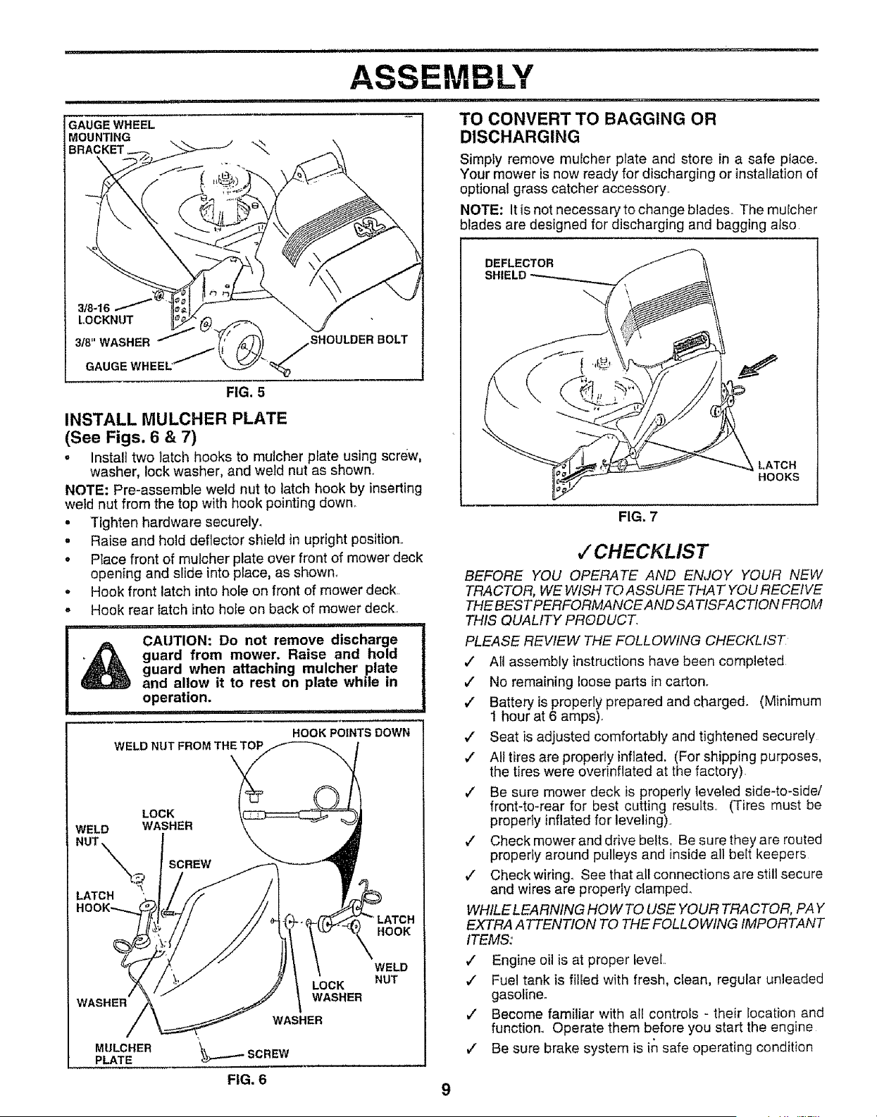
ASSEMBLE GAUGE WHEELS TO MOWER
DECK (See Fig. 5)
The gauge wheels are designed to keep the mower deck in
proper position when operating mower. Be sure they are
propedy adjusted to ensure optimum mower performance
o Assemble gauge wheels with tractor on a flat level
surface.
= Adjust mower to desired cutting height (See ''TO AD-
JUST MOWER CUTTING HEIGHT" in the Operation
section of this manual).
• With mower in desired height of cut position, gauge
wheels should be assembled so they are slightly off the
ground. Install gauge wheel in appropriate hole with
shoulder bolt, 3/8 washer, and 3/8-t6 locknut and
tighten securely
o Repeat for opposite side installing gauge wheel in
same adjustment hoie_
i ii ii ii ,,i iiii i,i1,111111, ,11 i..................... i,i
ASSEMBLY
ii 1,1,,111 ,,i i .....
GAUGE WHEEL
MOUNTING
BRACKET "_
TO CONVERT TO BAGGING OR
DISCHARGING
Simply remove mulcher plate and store in a safe place.
Your mower is now ready for discharging or installation of
optional grass catcher accessory..
NOTE: It is not necessary to change blades° The mulcher
blades are designed for discharging and bagging afso
3/8-16
I.OCKNUT (_j,_. "
SHOULDER/ BOLT
3/8"WASHER /
GAUGEWHEEL'_ _
FIG. 5
INSTALL MULCHER PLATE
(See Figs. 6 & 7)
o Instalt two latch hooks to mulcher plate using screw,
washer, lock washer, and weld nut as shown_
NOTE: Pre-assemble weld nut to latch hook by inserting
weld nut from the top with hook pointing down.
• Tighten hardware secureiy_
. Raise and hold deflector shield in upright position..
• Ptace front of mulcher plate over front of mower deck
open{rig and slide into place, as shown.
o Hook front latch into hole on front of mower deck..
, Hook rear fatch into hole on back of mower deck.
,,: i,, ii,,,, i i ,i,,nl,,i
I A CAUTION: Do not remove discharge
guard from mower. Raise and hold
guard when attaching mulcher plate
and allow it to rest on plate while in
operation.
,11 ,,11iii,
HOOK POINTS DOWN
WELD NUT FROM THE TOP
LOCK
WELD WASHER
NUT
,_ SCREW
LATCH
LATCH
HOOK
WASHER
LOCK
WASHER
WASHER
MULCHER
PLATE
WELD
NUT
DEFLECTOR
SHIELD
LATCH
HOOKS
FIG. 7
v" CHECKLIS T
BEFORE YOU OPERATE AND ENJOY YOUR NEW
TRACTOR, WEWISH TO ASSURE THAT YOU RECEIVE
THE BESTPERFORMANCEAND SATISFACTION FROM
THIS QUALITY PRODUCT.
PLEASE REVIEW THE FOLLOWING CHECKLIST
,/ All assembly instructions have been completed
,/ No remaining loose parts in carton_
v" Batteryis properly prepared and charged. (Minimum
t hour at 6 amps).
v" Seat is adjusted comfortably and tightened securely
/ All tires are properly inflated. (For shipping purposes,
the tires were overinflated at the factory).
,/ Be sure mower deck is properly leveled side-to-side/
front-to-rear for best cutting results.. (Tires must be
properly inflated for leveling)..
,/ Check mowerand drive belts, Be sure they are routed
properly around pulleys and inside all belt keepers
v" Check wiring, See that all connections are still secure
and wires are properly clamped.
WHILELEARNING HOW TO USE YOUR TRACTOR, PAY
EXTRA A TTENTION TO THE FOLLOWING IMPORTANT
ITEMS:
,/ Engine oil is at proper level..
,/ Fue! tank is filied with fresh, clean, regular unleaded
gasoline.
v" Become familiar with ale controls - their location and
function.. Operate them before you start the engine
€" Be sure brake system is in safe operating condition
FIG. 6
9
OPERATI
............ ,±,_ . i = "HH '
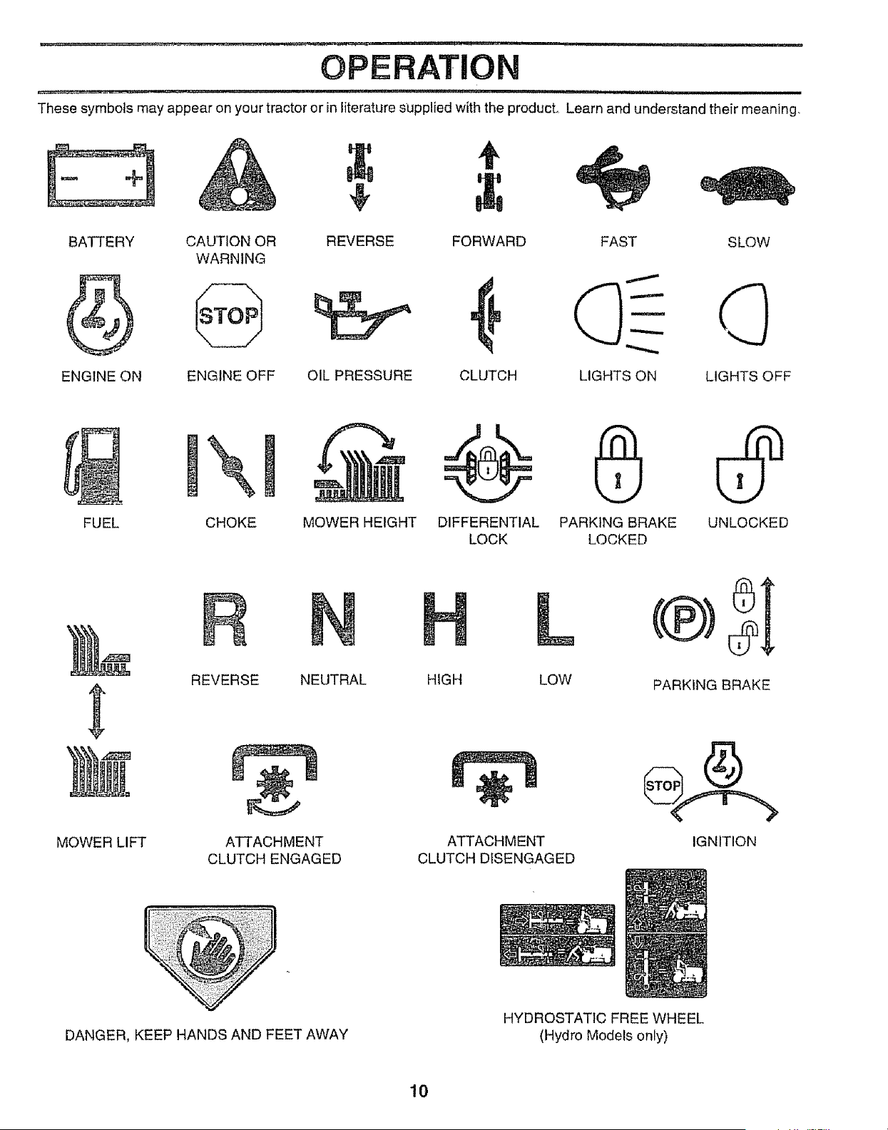
These symbols may appear on your tractor or in literature supplied with the producL Learn and understand their meaning.
÷
BATTERY
ENGINE ON
CAUTION OR REVERSE FORWARD FAST SLOW
WARNING
ENGINE OFF OIL PRESSURE CLUTCH LIGHTS ON LIGHTS OFF
FUEL CHOKE MOWER HEIGHT DIFFERENTIAL PARKING BRAKE UNLOCKED
LOCK LOCKED
MOWER LIFT
R
REVERSE NEUTRAL
ATTACHMENT
CLUTCH ENGAGED
L
HIGH LOW
ATTACHMENT
CLUTCH DISENGAGED
PARKING BRAKE
IGNITION
DANGER, KEEP HANDS AND FEET AWAY
HYDROSTATIC FREE WHEEL
(Hydro Models only)
10
, ' ,==,_u ,,i.............. =,,, ===l======lll===l=========
OPERATION
i ii i i i ii i, i i 'llrl , i I i i , ,11 ii i
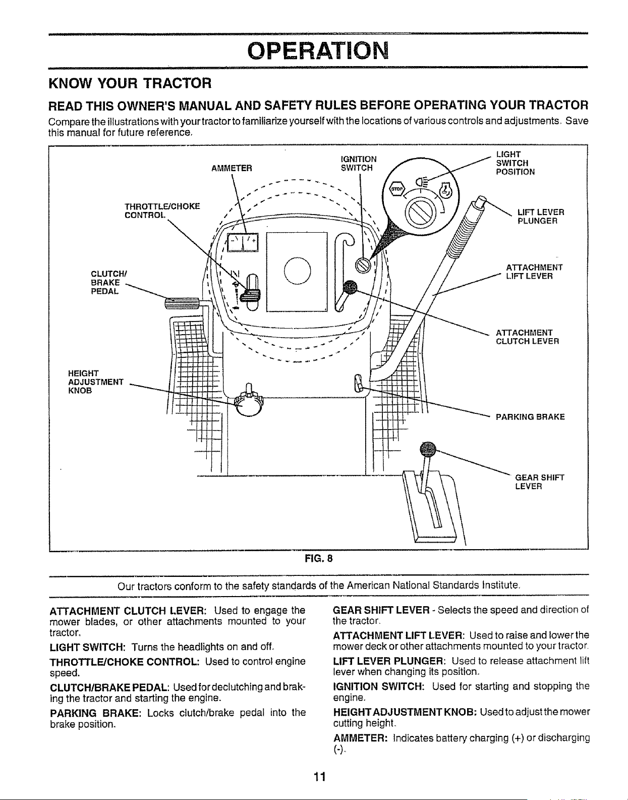
KNOW YOUR TRACTOR
READ THIS OWNER'S MANUAL AND SAFETY RULES BEFORE OPERATING YOUR TRACTOR
Compare the illustrationswith your tractorto familiarize yourself withthe locations of various controfs and adjustments. Save
this manual for future reference,
CLUTCH/
BRAKE
PEDAL
THROTTLE/CHOKE
CONTROL
LIGHT
IGNITION SWITCH
AMMETER SWITCH POSITION
©
LIFT LEVER
PLUNGER
ATTACHMENT
LIFT LEVER
HEIGHT
ADJUSTMENT
KNOB
ATTACHMENT
CLUTCH LEVER
PARKING BRAKE
GEAR SHIFT
LEVER
FIG, 8
Our tractors conform to the safety standards of the American National Standards institute,
ATTACHMENT CLUTCH LEVER: Used to engage the
mower blades, or other attachments mounted to your
tractor,
LIGHT SWITCH: Turns the headlights on and off°
THROTTLE/CHOKE CONTROL: Used to control engine
speed.
CLUTCH/BRAKE PEDAL: Used fordeclutching and brak _
ing the tractor and starting the engine.
PARKING BRAKE: Locks clutch/brake pedal into the
brake position.
GEAR SHIFT LEVER -Sefects the speed and direction of
the tractor.
ATTACHMENT LIFT LEVER: Used to raise and lower the
mower deck or other attachments mounted to your tractor.
LIFT LEVER PLUNGER: Used to release attachment lift
lever when changing its position.,
IGNITION SWITCH: Used for starting and stepping the
engine°
HEIGHT ADJUSTMENT KNOB: Used to adjust the mower
cutting height°
AMMETER: Indicates battery charging (+) or discharging
(4-
11
,i .......
OPERATION
' i, ii i ii .....ii
The operation of any tractor can result in foreign objects thrown into the eyes, which can
result in severe eye damage. Always wear safety glasses or eye shields while operating your
tractor or performing any adjustments or repairs. We recommend a wide vision safety mask
over the spectacles or standard safety glasses.
HOW TO USE YOUR TRACTOR
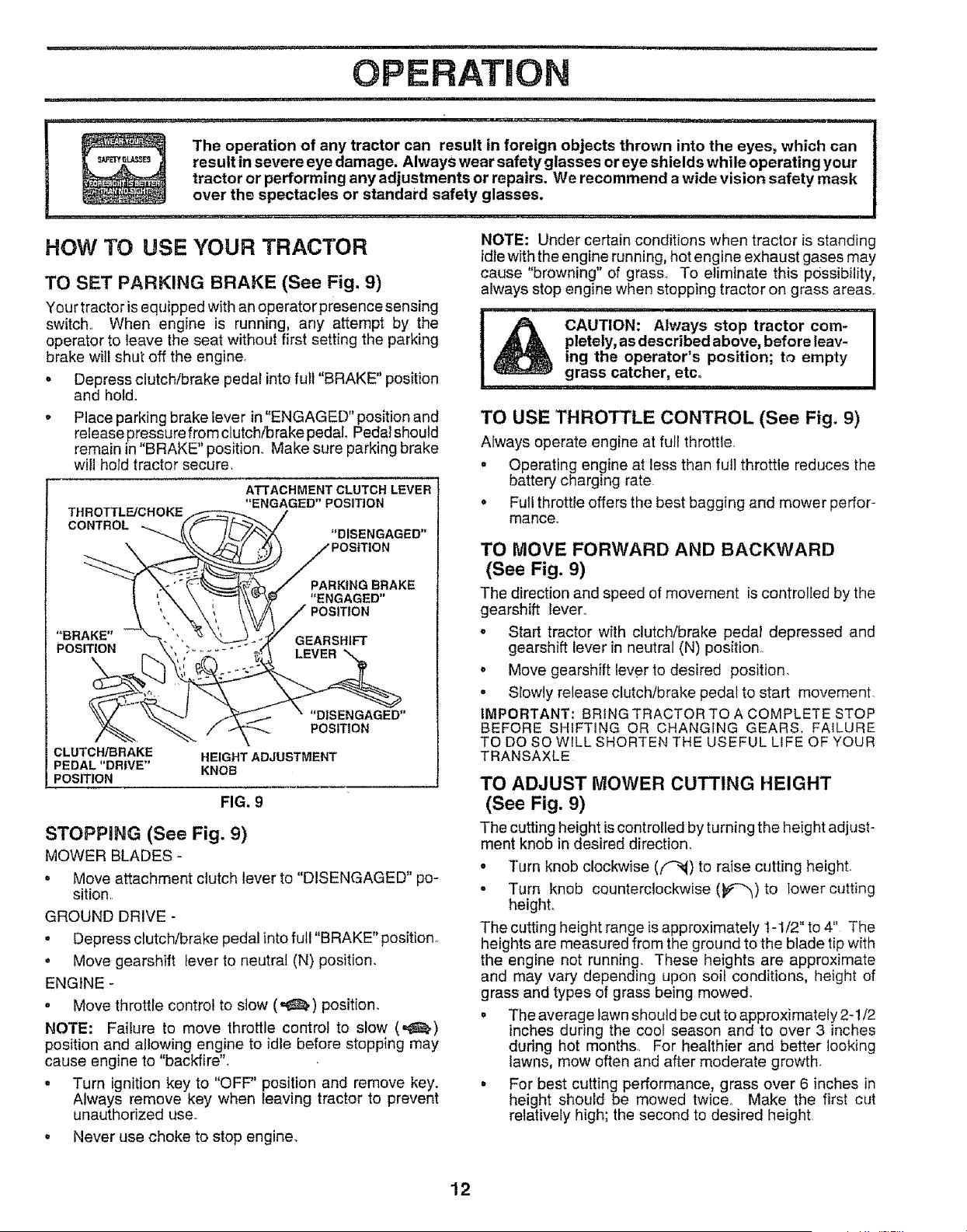
TO SET PARKING BRAKE (See Fig. 9)
Your tractor is equipped with an operator presence sensing
switch., When engine is running, any attempt by the
operator to leave the seat without first setting the parking
brake witl shut off the engine.
. Depress clutch!brake pedal into full "BRAKE" position
and hold.
. Place parking brake fever in "ENGAGED" position and
release pressure from clutch/brake pedal Pedalshould
remain in "BRAKE" position., Make sure parking brake
will hold tractor secure.
THROTTLFJCHOKE
CONTROL -_._
ATTACHMENT CLUTCH LEVER
"ENGAGED" POSITION
"DISENGAGED"
PARKING BRAKE
"ENGAGED"
"BRAKE" GEARSHIFT
POSITION
"DISENGAGED"
POSITION
CLUTOH/BRAKE HEIGHT ADJUSTMENT
PEDAL "DRIVE" KNOB
POSITION
FIG, 9
STOPPING (See Fig. 9)
MOWER BLADES -
• Move attachment clutch lever to "DISENGAGED" po-
sition.
GROUND DRIVE -
• Depress clutch/brake pedal into full "BRAKE" position,,
. Move gearshift lever to neutral (N) position.
ENGINE -
• Move throttle control to stow (_) position.
NOTE: Failure to move throttle control to slow (,_)
position and allowing engine to idle before stopping may
cause engine to "backfire".
• Turn ignition key to "OFF" position and remove key.
Always remove key when leaving tractor to prevent
unauthorized use.
° Never usa choke to stop engine_
NOTE: Under certain conditions when tractor is standing
idle with the engine running, hot engine exhaust gases may
cause "browning" of grass, To eliminate this possibility,
always stop engine when stopping tractor on grass areas,,
CAUTION: Always stop tractor com-
pletely, as described above, before leav-
ing the operator's position; to empty
grass catcher, etco
TO USE THROTTLE CONTROL (See Fig, 9)
AEways operate engine at full throttle,
= Operating engine at less than full throttle reduces the
battery charging rate
o Full throttle offers the best bagging and mower perfor-
mance.
TO MOVE FORWARD AND BACKWARD
(See Fig. 9)
The direction and speed of movement is controlled by the
gearshift lever,.
o Start tractor with clutch/brake pedal depressed and
gearshift lever in neutral (N) position,.
• Move gearshift lever to desired position.
- Slowly release clutch/brake pedal to start movement.
IMPORTANT: BRING TRACTOR TO A COMPLETE STOP
BEFORE SHIFTING OR CHANGING GEARS+ FAILURE
TO DO SO WILL SHORTEN THE USEFUL LIFE OF YOUR
TRANSAXLE
TO ADJUST MOWER CUTTING HEIGHT
(See Fig. 9)
The cutting height iscontrolled by turning the height adjust-
ment knob in desired direction_
• Turn knob clockwise ((_) to raise cutting height,
° Turn knob counterclockwise (_e'-_'_)to lower cutting
height.
The cutting height range is approximately 1-1/2" to 4" The
heights are measured from the ground to the btade tip with
the engine not running. These heights are approximate
and may vary depending upon soil conditions, height of
grass and types of grass being mowed.
= The average lawn should be cut to approximately 2-1/2
inches during the cool season and to over 3 inches
during hot months,, For healthier and better looking
lawns, mow often and after moderate growth,
° For best cutting performance, grass over 6 inches in
height should be mowed twice. Make the first cut
relatively high; the second to desired height
12
n,ll,i I , i " ", ................ i i, uu, n unl,lll,,Hi,u,n ..... lUll ' I I
OPERAT!O
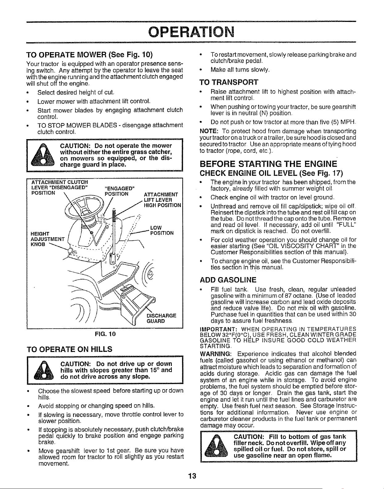
TO OPERATE MOWER (See Fig. 10)
Your tractor is equipped with an operator presence sens_
ing switch. Any attempt by the operator to leave the seat
with the engine running and the attachment clutch engaged
will shut off the engine.
o Select desired height of cut,
• Lower mower with attachment lift control.
. Start mower blades by engaging attachment clutch
control
° TO STOP MOWER BLADES - disengage attachment
clutch control
ii ..... r"'
CAUTION: Do not operate the mower
without either the entire grass catcher,
on mowers so equipped, or the dis-
charge guard in place.
ATTACHMENT CLUTCH
LEVER "DISENGAGED"
POSITION
/
HEIGHT
ADJUSTMENT
KNOB
"ENGAGED"
POSITION
ATTACHMENT
LIFT LEVER
HIGH POSITION
./
' LOW
._ POSITION
DISCHARGE
GUARD
FIG. 10
TO OPERATE ON HILLS
i,m
! oonot0"voo, ow°I
hills with slopes greater than 15° and I
do not drive across any slope. I
i i I i i i, i=
• Choose the slowest speed before starting up or down
hills.
• Avoid stopping or changing speed on hill&
• if slowing is necessary, move throttle control lever to
slower position°
° If stopping is absolutely necessary, push clutch/brake
pedal quickly to brake position and engage parking
brake,.
, Move gearshift lever to 1st gear. Be sure you have
allowed room for tractor to roll slightly as you restart
movement.
• To restart movement, slowly release parking brake and
clutch/brake pedal,.
• Make all turns slowly.
TO TRANSPORT
- Raise attachment lift to highest position with attach-
ment lift control,.
- When pushing or towing your tractor, be sure gearshift
lever is in neutral (N) position.
• Do not push or tow tractor at more than five (5) MPH,
NOTE: To protect hood from damage when transporting
your tractor on a truck or a trailer, be sure hood isclosed and
secured to tractor Use an appropriate means of tying hood
to tractor (rope, cord, etc.)..
BEFORE STARTING THE ENGINE
CHECK ENGINE OIL LEVEL (See Fig. 17)
- The engine in your tractor has been shipped, from the
factory, a_ready filfed with summer weight oil.
- Check engine oil with tractor on level ground
- Unthread and remove oil fill cap/dipstick; wipe oit off.
Reinsert the dipstick into the tube and rest oil fil! cap on
the tuber Do not thread the cap onto the tube. Remove
and read oil level. If necessary, add oil until "FULL"
mark on dipstick is reached. Do not overfiIL
, For cold weather operation you should change oi! for
easier starting (See "OIL VISCOSITY CHART" in the
Customer Responsibilities section of this manual)°
° To change engine oit, see the Customer Responsibili-
ties section in this manual
ADD GASOLINE
o Fil! fuel tank° Use fresh, clean, regular unteaded
gasoline with a minimum of 87 octane° (Use of leaded
gasoline will increase carbon and lead oxide deposits
and reduce valve life). Do not mix oil with gasoline.
Purchase fuel in quantities that can be used within 30
days to assure fuel freshness.
IMPORTANT: WHEN OPERATING iN TEMPERATURES
BELOW 32°F(0_C), USE FRESH, CLEAN WINTER GRADE
GASOLINE TO HELP INSURE GOOD COLD WEATHER
STARTING.
WARNING: Experience indicates that alcohol blended
fuels (called gasohol or using ethanol or methanol) can
attract moisture which leads to separation and formation of
acids during storage. Acidic gas can damage the fuel
system of an engine while in storage. To avoid engine
problems, the fuel system should be emptied before stor-
age of 30 days or longer. Drain the gas tank, start the
engine and let it run until the fuel lines and carburetor are
empty. Use fresh fuel next season. See Storage instruc-
tions for additional information. Never use engine or
carburetor cleaner products in the fuet tank or permanent
damage may occur.
! & CAUTION" Fill to bettol'_t_ of g as tank
filler neck. Do not overfill. Wipe off any
spilled oil or fuel. Do not store, spill or
use gasoline near an open flame.
i......
13
OPERATION
TO START ENGINE (See Fig. X)
When starting the engine for the first time or if the engine
has run out of fuef, it will take extra cranking time to move
fuel from the tank to the engine.
. Sit on seat in operating position, depress clutch/brake
pedal and set parking brake.
- Place gear shift _ever in neutral (N) position.,
o Move attachment clutch to "DISENGAGED" position,,
• Move throttle control to choke (N) position.
Note: Before starting, read the warm arid cold starting
procedures below
o insert key into ignition and turn key clockwise to"START'
position and release key as soon as engine starts,, Do
not run starter continuously for more than fifteen sec*
onds per minute. If the engine does not start after
several attempts, move throttle control to fast (,_)
dPOSition,wait a few minutes and try again, if engine still
oes not start, move the throttle control back to the
choke (N) position and retry.
WARM WEATHER STARTING (50 ° F and above)
. When engine starts, movethe throttle control to the fast
(.t._) position.
. The attachments and ground drive can now be used if
the engine does not accept the load, restart the engine
and allow it to warm up for one minute using the choke
as described above
COLD WEATHER STARTING ( 50° F and below)
- When engine starts, allow engine to run with the th rottle
control in the choke ( \ ) position until the engine runs
rough y, then move thrott e control to fast (,f_) post on.
This may require an engine warm-up period from
several seconds to several minutes, depending on the
temperature.
° The attachments can also be used during the engine
warm-up period.
NOTE: tf at a high altitude (above 3000 feet) or in cold
temperatures (below 32 F) the carburetor fuel mixture may
need to be adjusted for best engine performance. See"TO
ADJUST CARBURETOR" in the Service and Adjustments
section of this manual
MOWUNG TiPS
° Mower should be properly leveled for best mowing
performance. See "TO LEVEL MOWER HOUSING" in
the Service and Adjustments section of this manual,,
o The left hand side of mower should be used for trim-
ming,
o Drive so that clippings are discharged onto the area
that has been cut. Have the cut area to the right of the
machine. This will result in a more even distribution of
clippings and more uniform cutting.
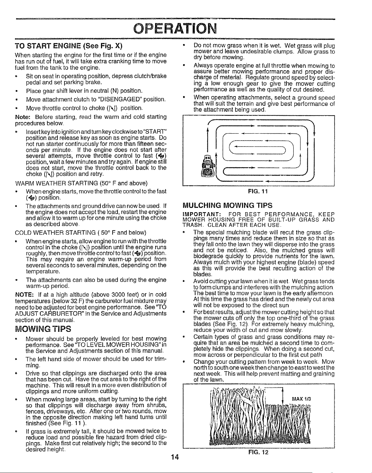
o When mowing large areas, start by turning to the right
so that clippings will discharge a,_ay from shrubs,
fences, driveways, etco After one ortwo rounds, mow
in the opposite direction making left hand turns until
finished (See Fig. 11 ).
o If grass is extremely tail, it should be mowed twice to
reduce load and possible fire hazard from dried clip-
pings. Make first cut relatively high; the second to the
desired heightr
• Do not mow grass when it is wet. Wet grass will plug
mower and leave undesirable clumps. Allow grass to
dry before mowing.
• Always operate engine at full throttle when mowing to
assure better mowing performance and proper dis-
charge of material Regulate ground speed by select-
ing a low enough gear to give the mower cutting
performance as well as the quality of cut desired.
• When operating attachments, select a ground speed
that wili suit the terrain and give best performance of
the attachment being used.
f
T
FIG. 11
MULCHING MOWING TIPS
IMPORTANT: FOR BEST PERFORMANCE, KEEP
MOWER HOUSING FREE OF BUILT-UP GRASS AND
TRASH, CLEAN AFTER EACH USE°
• The special mulching blade wilt recut the grass clip-
pings many times and reduce them in size so that as
they fall onto the lawn they will disperse into the grass
and not be noticed_ Also, the mulched grass witl
biodegrade quickly to provide nutrients for the lawn,
Always mulch with your highest engine (blade) speed
as this will provide the best recutting action of the
blade&
• Avoid cutting your lawn when it is wet. Wet grass tends
to form clumps and interferes with the mulching action
The best time to mow your lawn is the early afternoon
At this time the grass has dried and the newly cut area
will not be exposed to the direct sun
. For best resufts, adjust the mower cutting height so that
the mower cuts off only the top one-third of the grass
blades (See Fig, 12), For extremely heavy mulcl_ing,
reduce your width of cut and mow slowly.
• Certain types of grass and grass conditions may re-
quire that an area be mulched a second time to com-
pletely hide the clippings, When doing a second cut,
mow across or perpendicular to the first cut path
• Change your cutting pattern from week to week, Mow
north to south one week then change to east to west the
next week. This will help prevent matting and graining
of the lawn.
MAX 1/3
FIG, 12
14
JJ = 1,1,,i , =,,====== .................. =,,==1
CUSTOMER RESPONSiBiLiTiES
iiii i i I I i[ iJ Jl ..................... 1,1,1,,,,,,i,,I,
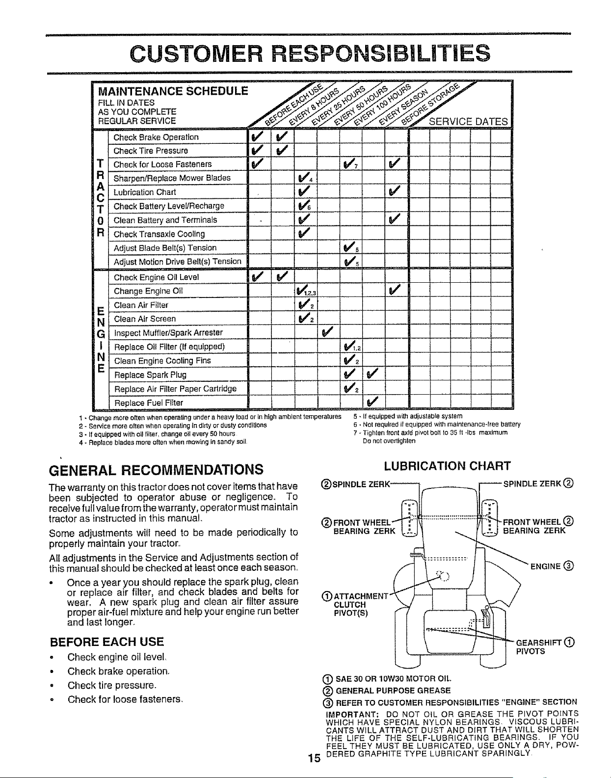
MAINTENANCESC.EDULE
FILL,NDATES
ASYouCOMPL_E _'_..%'_.1_,_÷'_._0_"
REGU RSERWOE................ SERVICEDATES
Check Brake Operation if if
Check Tire Pressure , _ V '_ . If , ,
.......v', I/
T Check for Loose Fasteners I_
R sharpen/Replace Mowe'r"Blades .......
cA Lubricati;nChaa ........
T Che,c,kBatteryLevel,'Recha,rge
0 C{ean Battery and Terminals
a Check Transaxle Cooling
Adjust_ Blade Belt(s) Tensio,n .....
Adjust Motion Drive Belt(s) Tension
Check Engine,,Oil Level ......... j,,l_#
Change Engine Oil
E I clean Air Filter ........
N I Clean Air Screen ............
G i Inspect Muffler/Spark Ar!es!,er ........
I Replace Oil Filter (If equipped)
N:,............
Clean Engine Coo!,i,ng, Fins ,,,
Replace Spark Plug
Replace Air Filter Paper Cartridge
Replace Fuel Filter
v',
v' jr"
v' v'
v'
v',
k , ,,j_,,_ ,r,
v"
' ' ' z
V_ .......
v' v"
v"
,, ,,,,_, ,,,,
I _ Change more often when operating under a heavy ioad or in high ambient temperatures
2 - Service more otten when opera_Jng in dirty or dusty conditions
3 - If equipped with e_t tilter, change o_teve_ 50 hours
4 - Replace b_adee mere often when mewing In sandy soil
5 - ff equipped with adjustat)_e system
6 - Not required if equipped with matnfenance4ree baltery
7 - Tighfen freer axld pivot bo_f to 35 ft 4be maximum
Do not oveftlghten
GENERAL RECOMMENDATIONS
The warranty on this tractor does not cover items that have
been subjected to operator abuse or negligence. To
receive full value from the warranty, operator must maintain
tractor as instructed in this manual
Some adjustments will need to be made periodically to
properly maintain your tractor.,
All adjustments in the Service and Adjustments section of
this manual should be checked at least once each season.,
• Once a year you should replace the spark plug, clean
or replace air filter, and check blades and belts for
wear° A new spark plug and clean air filter assure
proper air-fuel mixture and help your engine run better
and last longer,,
BEFORE EACH USE
- Check engine oil level.
• Check brake operation.
o Checktire pressure.
o Check for loose fasteners.
LUBRICATION CHART
@ ®
@
®
_BEARtNG ZERK BEARING ZERK
®
(_) CLUTCH
PIVOT(S)
IEARSHIFT (_
PIVOTS
(_ SAE 30 OR 10W30 MOTOR OIL
® GENERAL PURPOSE GREASE
® REFER TO CUSTOMER RESPONSIBILITIES "ENGINE" SECTION
IMPORTANT: DO NOT OtL OR GREASE THE PIVOT POINTS
WHICH HAVE SPECIAL NYLON BEARINGS VISCOUS LUBRI-
CANTS WILL ATTRACT DUST AND DIRT THAT WELL SHORTEN
THE LIFE OF THE SELF-LUBRICATING BEARINGS, IF YOU
FEEL THEY MUST BE LUBRICATED, USE ONLY A DRY, Pew-
15 DERED GRAPHITE TYPE LUBRICANT SPARINGLY
' ' ',,,",'", i,,i,,111¸ ,,, i i ,i ,,ll,i
CUSTOMER LI ES
.. Ul._ ,,,11,,, i ,
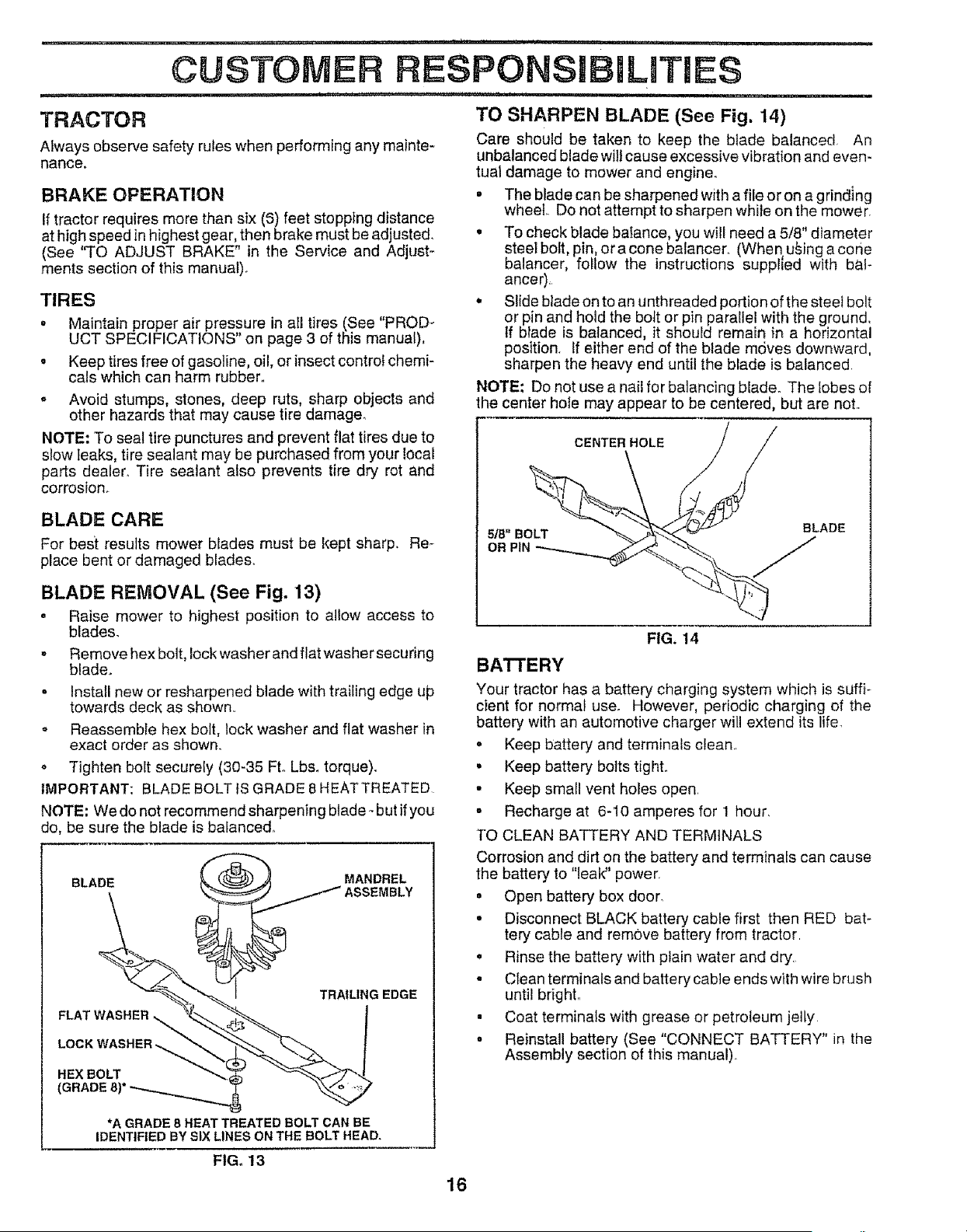
TRACTOR TO SHARPEN BLADE (See Fig. 14)
Always observe safety rules when performing any mainte- Care should be taken to keep the blade balanced, An
unbalanced blade will cause excessive vibration and even-
nance, tual damage to mower and engine_
BRAKE OPERATION • The blade can be sharpened with a file or on a grinding
If tractor requires more than six (_) feet stopping distance wheel. Do not attempt to sharpen while on the mower,
at high speed in highest gear, then brake must be adjusted. • To check blade balance, you will need a 5/8" diameter
(See 'q'O ADJUST BRAKE" in the Service and Adjust- steel bolt, pin, or a cone baiancero (When u_ing a cone
merits section of this manual), balancer, follow the instructions supplled with bai-
ancer),
TIRES • Slide blade on to an unthreaded portion of the steel bolt
° Maintain proper air pressure in ati tires (See "PROD- or pin and hold the bolt or pin parallel with the ground,
UCT SPECIFICATIONS" on page 3 of this manual), If blade is balanced, it should remain in a horizontal
position, tf either end of the blade moves downward,
o Keep tires free of gasoline, oil, or insect control chemi- sharpen the heavy end until the blade is balanced
cals which can harm rubber,, NOTE: Do not use a nail for balancing blade. The tobes of
o Avoid stumps, stones, deep ruts, sharp objects and the center hole may appear to be centered, but are not,,
other hazards that may cause tire damage,
NOTE: To seal tire punctures and prevent flat tires due to CENTERHOLE
SlOWleaks, tire sealant may be purchased from your local
parts dealer_ Tire sealant also prevents tire dry rot and
corrosion_
BLADE CARE
5/8" BOLT BLADE
For best results mower blades must be kept sharp. Re- OR PIN
place bent or damaged blade&
BLADE REMOVAL (See Fig. 13)
= Raise mower to highest position to allow access to
blades. FIG. 14
. Remove hex bolt, lock washer and flat washer securing
blade_ BATTERY
. Install new or resharpened blade with trailing edge up Your tractor has a battery charging system which is surf}-
towards deck as shown° cient for normal use. However, periodic charging of the
= Reassemble hex bolt, lock washer and flat washer in battery with an automotive charger will extend its life.
exact order as shown. • Keep battery and terminals clean,,
o Tighten bolt securely (30-35 FL Lbs, torque)° • Keep battery bolts t}ght,,
IMPORTANT: BLADE BOLT fS GRADE 8 HEAT TREATED • Keep small vent holes open,
NOTE: Wedonot recommendsharpening btade-butifyou o Recharge at 6-10 amperes for 1 hour.
do, be sure the blade is balanced,, ]'O CLEAN BATTERY AND TERMINALS
Corrosion and dirt on the battery and terminals can cause
BLADE MANDREL the battery to "leak" power,
• Open battery box door
° Disconnect BLACK battery cable first then RED bat-
tery cable and remove battery from tractor,
• Rinse the battery with plain water and dry.
• Clean terminals and battery cable ends with wire brush
TRAILING EDGE until bright,,
FLATWASHER "'_" _""__. ! • Coat terminals with grease or petroleum jelly
LOCK _.___"_..,.._." ° Reinstall battery (See "CONNECT BATTERY" in the
Assembly section of this manual),
HEX BOLT
•A GRADE 8 HEAT TREATED BOLT CAN BE
IDENTtRED BY SIX LINES ON THE BOLT HEAD.
FIG. 13
16
CUSTOMER BILITi
................... H ................. i t
V-BELTS
Check V-betts for deterioration and wear after 100 hours of
operation and replace if necessary, The belts are not
adjustable. Replace belts if they begin to slip from wear.
TRANSAXLE COOLING
Keep transaxle free from build-up of dirt and chaff which
can restrict cooiingo
ENGINE
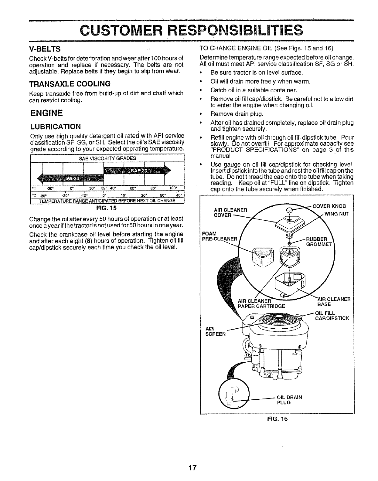
LUBRICATION
Only use high quality detergent oil rated with AFH service
classification SF, SG, or SH, Select the oil's SAE viscosity
grade according to your expected operating temperature°
SAE VISCOSITY GRADES
°F, -20 _ O" 30= 32° 40 _ 60 ° gO _ 1004
oC Oo
-30_ -20 ° -10" '[0° 20_' 30° 40=
TEMPERATURE RANGE ANTICIPATED BEFORE NEXT OIL CHANGE
FIG. 15
Change the oil after every 50 hours of operation or at least
once a year if the tractor is not used for 50 hours inone year.
Check the crankcase oil level before starting the engine
and after each eight (8) hours of operation° Tighten oil fil!
cap/dipstick securely each time you check the oil level,
TO CHANGE ENGINE OIL (See Figs 15 and 16)
Determine temperature range expected before oil change
All oil must meet API service classification SF, SG or SH
• Be sure tractor is on level surface
• Oil will drain more freely when warm_
• Catch oil in a suitable container°
. Remove oil fill cap/dipstick, Be careful not to allow dirt
to enter the engine when changing oil
• Remove drain plug.
° After oil has drained completely, replace oil drain plug
and tighten securely
• Refill engine with oil through oil fill dipstick tube. Pour
slowly. Do not overfill, For approximate capacity see
"PRODUCT SPECIFICATIONS" on page 3 of this
manual
= Use gauge on oil fill cap/dipstick for checking level.
Insert dipstick intothe tube and rest the oil fill cap on the
tube. Do not thread the cap onto the tube when taking
reading° Keep oil at "FULL" line on dipstick, Tighten
cap onto the tube securely when finished°
KNOB
AIR CLEANER
COVER . WING NUT
FOAM
PRE-CLEANER
AIR
SCREEN
PAPER CARTRIDGE
BASE
OIL FILL
CAP/DIPSTiCK
:lAIN
PLUG
FIG. 16
17
........... i i _ ..=LI ,t,_., i " I .... irll i I ' I
CUSTO RESPON BILITmES
CLEAN AIR SCREEN (See Fig. 16)
Air screen must be kept free of dirt and chaff to prevent
engine damage from overheating. Clean with a wire brusll
or compressed air to remove dirt and stubborn drieU gum
fibers°
AIR FILTER (See Fig. 16)
Your engine will not run properly using a dirty air filter_
Clean the foam pre-cieaner after every 25 hours of opera-
tion or every season, Service paper cartridge every 100
hours of operation or evei'y season, whichever Occurs first°
Service air cleaner more often under dusty conditions.
• Remove knob and cover,
° Remove wing nut and air cleaner from base.
TO SERVICE PRE-CLEANER
. SIide foam pre-cleaner off cartridge.
- Wash it in liquid detergent and water.
- Squeeze it dry in a clean cloth. Atlow it to dry.
- Saturate it in engine oil. Wrap it in clean, absorbent
cloth and squeeze to remove excess oil,
TO SERVICE CARTRIDGE
• Replace a dirty, bent, or damaged cartridge_
NOTE: Do notwashthepapercartridgeorusepressudzed
air, as this wilt damage the cartridge.,
= Reinstall the pre-cleaner (cleaned and oiled) over the
paper cartridge.
o Reassemble air cleaner, wing nut, cover and tighten
knob securely.
CLEAN AIR INTAKE/COOLING AREAS
To insure proper cooling, make sure th_ grass _creen_
cooling fins, and other external surfaces of the engine _.re
kept clean at ali times.
Every 1O0 hours of operation (more often under extremely
dusty, dirty conditions), remove the b{ower housing and
other cooling shrouds. Clean the cooling fins ahd exterhal
surfaces as necessary. MaRe sure the Cooling shrouds ale
reinstalled.
NOTE; Operating the engirie with a blocked gras¢ screen,
dirty or plugged cooling fins, and/or cooling shrouds re-
moved will cause engine damage due to overheating,
MUFFLER
inspect and replace corroded muffler and spark arrester (if
eqt,_ipped) as it could create a fire hazard and/or damage
SPARK PLUGS
Replace spark plugs at the beginning of each mowing
season or after every 100 hours of operation, whichever
occurs first. Spark plug type and gap setting are shown in
"PRODUCT SPECIFICATIONS" on page 3 of this manual
18
I i=, ,=J i1,,i i, i,l,lr,
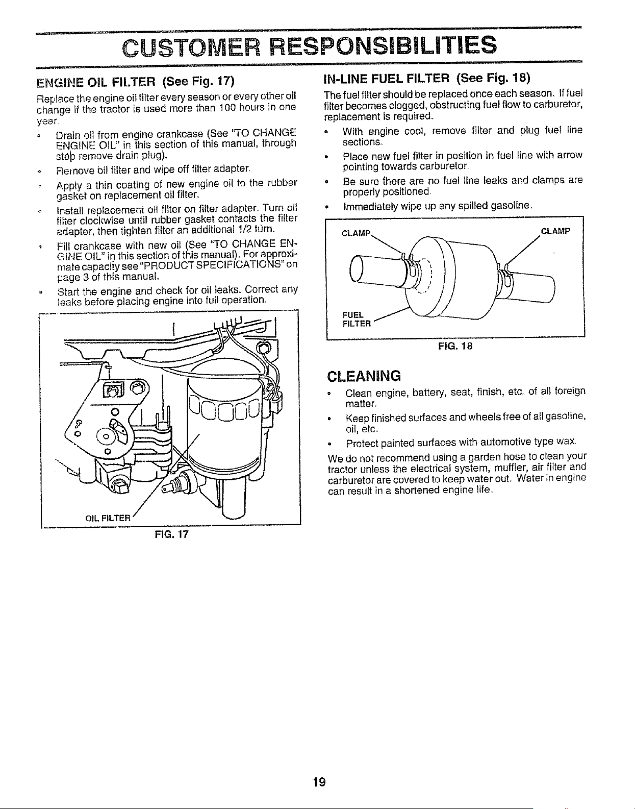
ENGIHE OiL FILTER (See Fig. 17)
Replace the engine oiI filter every season or every other oil
change if the tractor is used mere than 100 hours in one
year
o Drain oit from engine crankcase (See 'q'(.3 CHANGE
ENGINE OIL:' in this section of this manual, through
ste_ remove drain plug).
o Remove bil filter and wipe off filter adapter.
, Apply a thin coating of new engine oil to the rubber
gasket on replacement oil filter.
Install replacement oil filter on filter adapter. Turn oi!
filter clocle,vise until rubber gasket contacts the filter
adapter, then tighten filter an additional 1/2 torn.
Fill crankcase with new oil (See 'q'O CHANGE EN-
GINE OIL" in this section of this manual). For approxi-
mate capacity see "PRODUCT SPECIFICATIONS" on
page 3 of this manual.
o Start the engine and check for oil leaks. Correct any
leaks before placing engine into full operation.
OIL FILTER
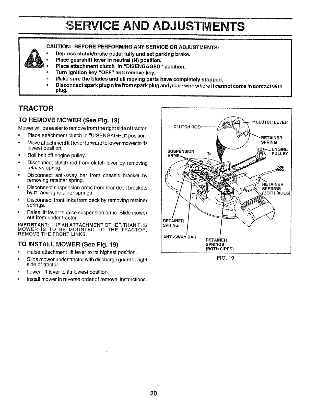
IN-LINE FUEL FILTER (See Fig. 18)
The fuel filter should be replaced once each season_ If fuel
filter becomes clogged, obstructing fuel flow to carburetor,
replacement is required.
o With engine coot, remove filter and plug fuel line
sections.
• Place new fuel filter in position in fuel line with arrow
pointing towards carburetor..
o Be sure _here are no fuel line leaks and clamps are
properly positioned.
, Immediately wipe up any spilled gasoline.
CLAMP.
CLAMP
FIG. 18
CLEANRNG
o Clean engine, battery, seat, finish, etco of all foreign
matter.
, Keep finished surfaces and wheels free of all gasoline,
oil, etc.
o Protect painted surfaces with automotive type wax.
We do not recommend using a garden hose to clean your
tractor unless the electrical system, muffler, air filter and
carburetor are covered to keep water out. Water in engine
can result in a shortened engine life
FIG. 17
19
=,1,,, ,i,,
SERVICE
H'"I'M,H" I
"1' I,,,,,,,'.......... '111 I
I" ' I
ADJUSTMENTS
H,,II, i ii,i, 1,1,11,1i, i
• i,i i ii
O
O
O
O
O
CAUTION: BEFORE PERFORMING ANY SERVICE OR ADJUSTMENTS:
Depress clutch/brake pedal fully and set parking brake,
Place gearshift lever in neutral (N) position.
Place attachment clutch in "DISENGAGED" position.
Turn ignition key "OFF" and remove key.
Make sure the blades and all moving parts have completely stopped.
Disconnect spark plug wire from spark plug and place wire where it cannot come in contact with
plug.
i, ,1,1.,i,1,,,i ii 11111,111111I
TRACTOR
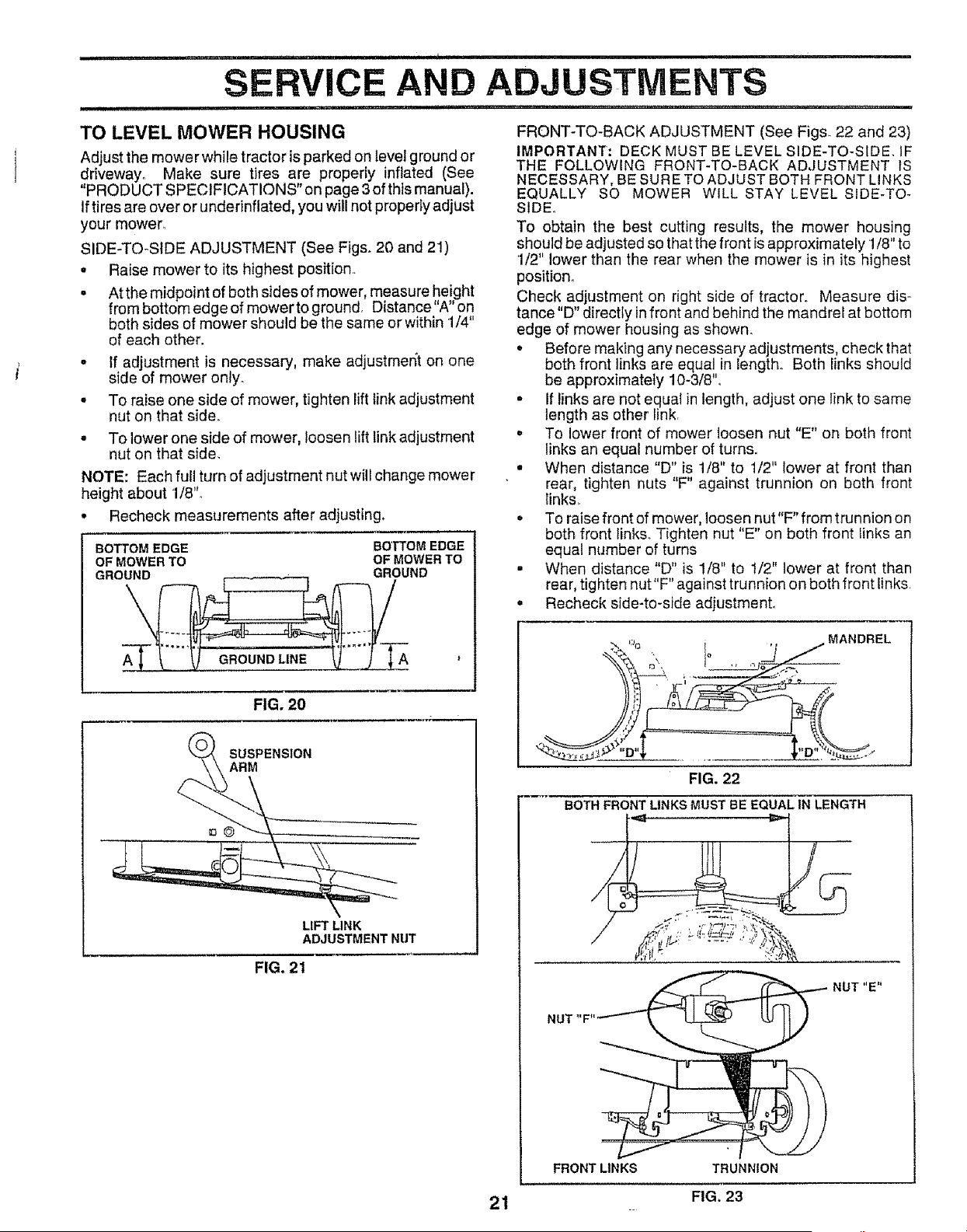
TO REMOVE MOWER (See Fig. 19)
Mower will be easier to remove from the right side of tractor.
• Place attachment clutch in "DISENGAGED" position,
. Move attachment lift lever forward to lower mower to its
lowest position
• Roll belt off engine pulley°
o Disconnect clutch rod from clutch [ever by removing
retainer spring°
, Disconnect anti-sway bar from chassis bracket by
removing retainer spring.
• Disconnect suspension arms from rear deck brackets
by removing retainer springs.
o Disconnect front links from deck by removing retainer
spnngs.
° Raise lift lever to raise suspension arms. Slide mower
out from under tractor
IMPORTANT: IF AN ATTACHMENT OTHER THAN THE
MOWER IS TO BE MOUNTED TO THE TRACTOR,
REMOVE THE FRONT LINKS,
TO INSTALL MOWER (See Fig. 19)
• Raise attachment liftlever to its highest position.
• Stide mower under tractor with discharge guard to right
side of tractor_
= Lower lift iever to its lowest position,
. Install mower in reverse order of removal instructions.
CLUTCH I
SUSPENSION
RETAINER
SPRING
ANTI-SWAY BAR
RETAINER
SPRINGS
(BOTH SIDES)
FIG. 19
2O
i == == n.. i ....... i i i= i i i III_Nlll r
RVICE AN ADJUSTMENTS
i, , i i, 1,1,11111
TO LEVEL MOWER HOUSING
Adjust the mower while tractor is parked on level ground or
driveway,, Make sure tires are properly inflated (See
"PRODUCT SPECIFICATIONS" on page 3 of this manual).
If tires are over or underinflated, you will not properly adjust
your mower_
SIDE-TO-SIDE ADJUSTMENT (See Figs_20 and 2!)
o Raise mower to its highest position,
• At the midpoint of both sides of mower, measure height
from bottom edge of mower to ground, Distance "A" on
both sides of mower should be the same or within 1/4"
of each other.
° If adjustment is necessary, make adjustmen_t on one
side of mower only.
° To raise one side of mower, tighten lift link adjustment
nut on that side.
• To lower one side of mower, loosen lift link adjustment
nut on that side,
NOTE: Each full turn of adjustment nut will change mower
height about 1/8"o
• Recheck measurements after adjusting.
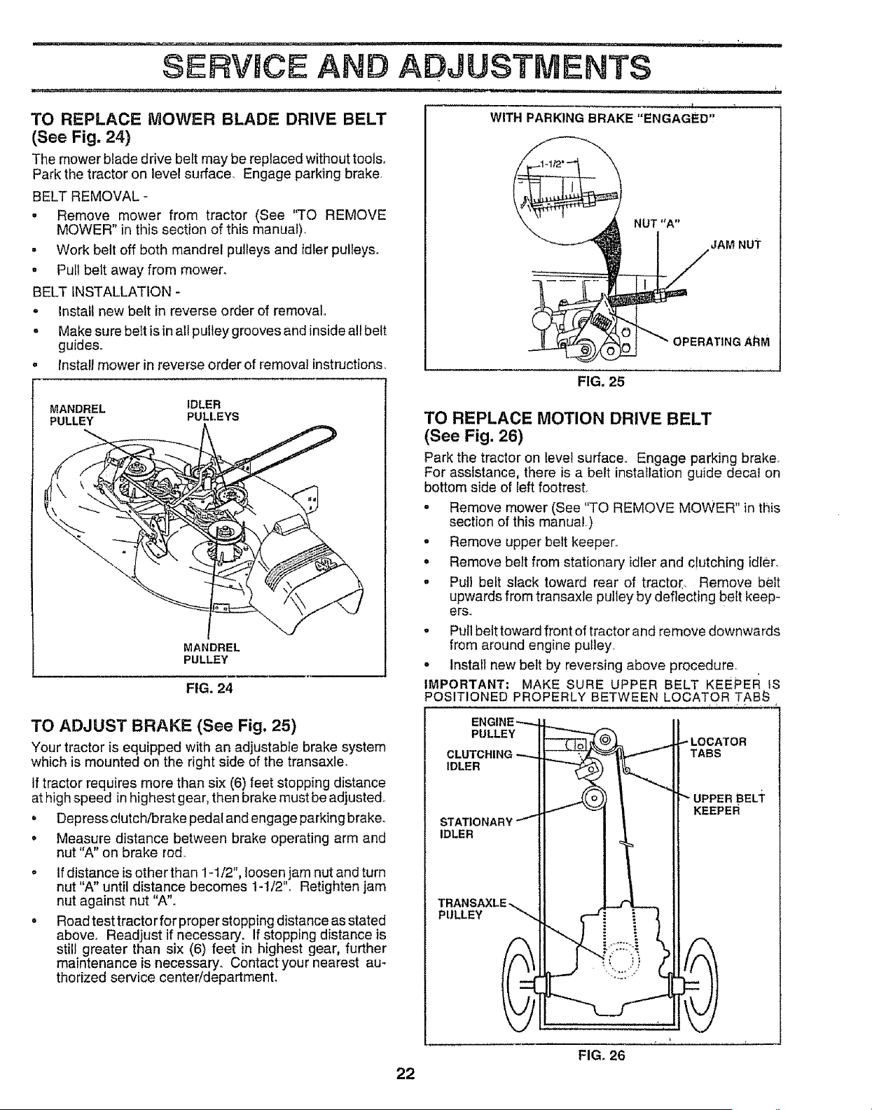
FRONT-TO-BACK ADJUSTMENT (See Figs. 22 and 23)
IMPORTANT; DECK MUST BE LEVEL SIDE-TO-SiDE. IF
THE FOLLOWING FRONT-TO-BACK ADJUSTMENT iS
NECESSARY, BE SURE TO ADJUST BOTH FRONT LINKS
EQUALLY SO MOWER WILL STAY LEVEL SIDE-TO-
SIDE.,
To obtain the best cutting results, the mower housing
should be adjusted so that the front is approximately 1/8" to
1/2" lower than the rear when the mower is in its highest
position°
Check adjustment on right side of tractor,, Measure dis-
tance"D" directly in front and behind the mandrel at bottom
edge of mower housing as shown_
• Before making any necessary adjustments, check that
both front links are equal in length. Both links should
be approximately 10-3/8"o
• If links are not equal in length, adjust one link to same
length as other link.
o To lower front of mower loosen nut "E" on both front
links an equal number of turns°
° When distance "D" is 1/8" to 1/2" lower at front than
rear, tighten nuts "F" against trunnion on both front
Iinks,
o To raise front of mower, loosen nut"F" from trunnion on
both front links., Tighten nut "E" on both front links an
equal number of turns
• When distance "D" is 1/8" to t/2" lower at front than
rear, tighten nut"F" against trunnion on both front links,
• Recheck side-to-side adjustment°
BOTTOM EDGE BO'FI'OM EDGE
OF MOWER TO OF MOWER TO
GROUND GROUND
GROUND LINE A '
LIFT LINK
ADJUSTMENT NUT
FIG. 2O
SUSPENSION
ARM
FIG. 21
% , MANDREL
FIG. 22
BOTH FRONT LINKS MUST BE EQUAL IN LENGTH
NUT "E"
NUT "F"
FRONT LINKS TRUNNION
FIG. 23
........ i,ii ......
SERVSCE AND ADJUSTMENTS
TO REPLACE MOWER BLADE DRIVE BELT
(See Fig. 24}
The mower blade drive belt may be replaced without tools_
Park the tractor on level surface. Engage parking brake.
BELT REMOVAL -
• Remove mower from tractor (See "TO REMOVE
MOWER" in this section of this manual),
= Work belt off both mandrel pulleys and idler pulleys_
, Pu_Ibelt away from mower_
BELT INSTALLATION -
- Install new belt in reverse order of removal.,
= Make su re belt is in all pulley grooves and inside all belt
guides,.
= Instal] mower in reverse order of removal instructions,,
MANDREL IDLER
PULLEY PULLEYS
MANDREL
PULLEY
FIG, 24
WITH PARKING BRAKE "ENGAGED'!
NUT "A"
JAM NUT
OPERATING A_M
FIG. 25
TO REPLACE MOTION DRIVE BELT
(See Fig. 26)
Park the tractor on level surface., Engage parking brake.
For assistance, there is a belt installation guide decal on
bottom side of left footrest.
o Remove mower (See "TO REMOVE MOWER" in this
section of this manual.)
o Remove upper belt keeper,,
, Remove belt from stationary idler and clutching idler.
• Pull belt slack toward rear of tracto[, Remove beet
upwards from transaxle pulley by deflecting belt keep-
ers.
° Pull belt toward front of tractor and remove downwards
from around engine pulley,
o Install new belt by reversing above procedure
IMPORTANT: MAKE SURE UPPER BELT KEEPEF_ iS
POSITIONED PROPERLY BETWEEN LOCATOR TABS
TO ADJUST BRAKE (See Fig, 25)
Your tractor is equipped with an adjustable brake system
which is mounted on the right side of the transaxle,
If tractor requires more than six (6) feet stopping distance
at high speed in highest gear, then brake must be adjusted.
, Depress clutch/brake pedal and engage parking brake_
• Measure distance between brake operating arm and
nut"A" on brake rod.
If distance is other than 1-1/2", loosen jam nut and turn
nut "A" until distance becomes 1-1/2"o Retighten jam
nut against nut "A".
Road test tractor for proper stopping distance as stated
above° Readjust if necessary, if stopping distance is
still greater than six (6) feet in highest gear, further
maintenance is necessary° Contact your nearest au-
thorized service center/department.
PULLEY
IDLER
IDLER
PULLEY
TABS
KEEPER
22
FIG. 26
r,_,,....................
SERVICE AND
........................................ i 'l"r r
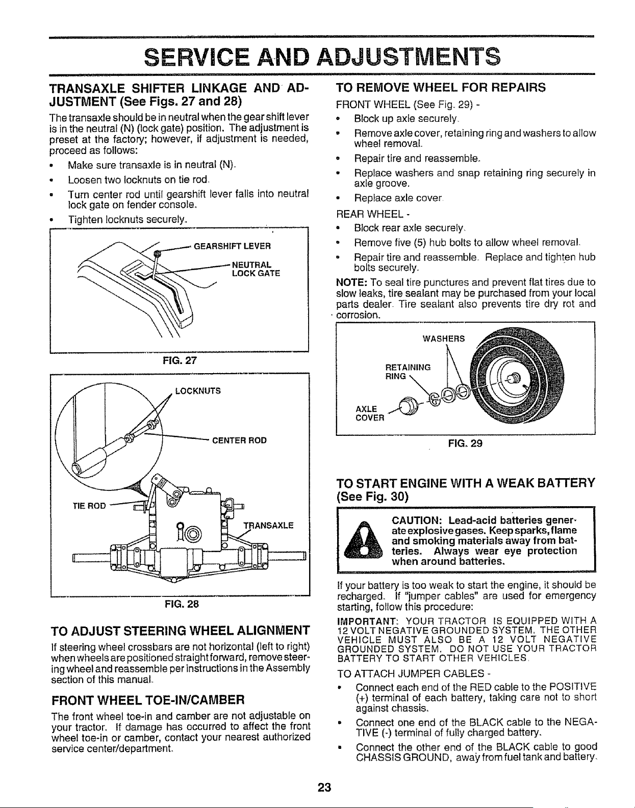
TRANSAXLE SHIFTER LINKAGE AND AD-
JUSTMENT (See Figs. 27 and 28)
ADJUSTMENTS
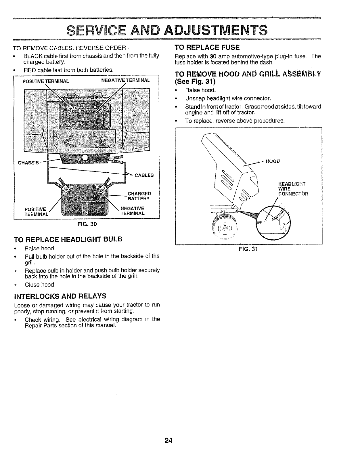
TO REMOVE WHEEL FOR REPAIRS
FRONT WHEEL (See Fig_ 29) -
The transaxle should be in neutral when the gear shift lever
is inthe neutral (N) (lock gate) position, The adjustment is
preset at the factory; however, if adjustment is needed,
proceed as follows:
• Make sure transaxle is in neutral (N)_
. Loosen two locknuts on tie rod.
Turn center rod until gearshift lever falls into neutral
lock gate on fender console°
• Block up axle securely.
- Remove axle cover, retaining ring and washers to allow
wheel removal..
= Repair tire and reassemble.
• Replace washers and snap retaining ring securely in
axie groove.
° Replace axle cover
Tighten locknuts securely.
FIG. 27
__CKNUTS
/ _ CENTER ROD
FIG. 28
TO ADJUST STEERING WHEEL ALIGNMENT
If steering wheel crossbars are not horizontal (teft to right)
when wheels are positioned straight forward, remove steer-
ing wheel and reassemble per instructions in the Assembly
section of this manual.,
FRONT WHEEL TOE-IN/CAMBER
The front wheel toe-in and camber are not adjustable on
your tractor_ If damage has occurred to affect the front
wheel toe-in or camber, contact your nearest authorized
service center/departmento
REAR WHEEL -
. Block rear axle securely.
= Remove five (5) hub bolts to allow wheel removal
- Repair tire and reassemble. Replace and tighten hub
bolts securely.
NOTE: To seal tire punctures and prevent flat tires due to
slow leaks, tire sealant may be purchased from your local
)arts dealer_ Tire sealant also prevents tire dry rot and
corrosion.
WASHERS
RETAINING
RING
FIG. 29
AXLE
COVER
TO STARTENGINEWITHAWEAK BA'I-rERY
See Fig. 30)
CAUTION: Lead-acid bakeries gener-
ateexplosivegases. Keep sparks,flame
and smoking materials away from bat-
teries, Always wear eye protection
when around batteries,
i n,=,,u,n,,
If your battery is too weak to start the engine, it should be
recharged° If "jumper cables" are used for emergency
starting, follow this procedure:
IMPORTANT: YOUR TRACTOR IS EQUIPPED WITHA
12 VOLT NEGATIVE GROUNDED SYSTEM, THE OTHER
VEHICLE MUST ALSO BE A 12 VOLT NEGATIVE
GROUNDED SYSTEM, DO NOT USE YOUR TRACTOR
BATTERY TO START OTHER VEHICLES,
TO ATTACH JUMPER CABLES
• Connect each end of the RED cable to the POSITIVE
(+) terminal of each battery, taking care not to short
against chassis.
• Connect one end of the BLACK cable to the NEGA-
TIVE (-) terminal of fully charged battery.
. Connect the other end of the BLACK cable to good
CHASSIS GROUND, away' from fuel tankand battery.
23
SERVICE AND ADJUSTMENTS
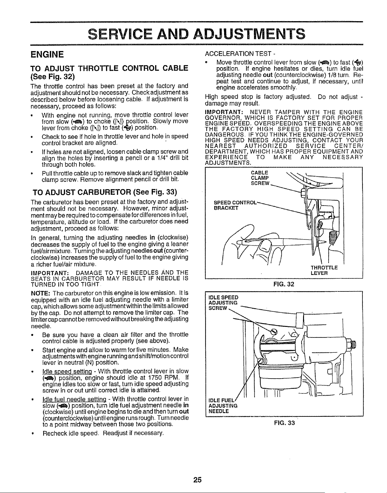
TO REMOVE CABLES, REVERSE ORDER -
• BLACK cable first from chassis and then from the fully
charged battery..
° RED cable last from both batteries.
POSITIVE TERMINAL
NEGATIVE 1 ERMINAL
CHARGED
BATTERY
POSITIVE NEGATIVE
TERMINAL TERMINAL
FIG. 30
TO REPLACE HEADLIGHT BULB
, Raise hood.
, Pull bulb holder out of the hole in the backside of the
grill.
o Replace bulb in holder and push bulb holder securely
back into the hote in the backside of the grilt.
o Close hood°
TO REPLACE FUSE
Replace with 30 amp aut0motive-type plug'in fuse ]'he
fuse holder is located behind the dash
TO REMOVE HOOD AND GRILL A @i tvlBL',,
(See Fig. 31)
• Raise hood.
• Unsnap headlight wire connector,
° Stand in front of tractor_ Grasp hood at sideS, tilt toward
engine and lift off of tractor.
• To replace, reverse above procedures.
\
HOOD
HEADLIGI_T
WIRE
CONNECTOR
FIG. 31
INTERLOCKS AND RELAYS
Loose or damaged wiring may cause your tractor to run
poorly, stop running, or prevent it from starting.
- Check widng.. See electrical wiring diagram in the
Repair Parts section of this manual.
24
............................ i , , , i i i i .........................................
SERVICE ADJUSTMENTS
i i ,i i,, ii1,1 i ,i,ii1,, I ..... i i i
ENGINE ACCELERATION TEST-
TO ADJUST THROTTLE CONTROL CABLE
(See Fig. 32)
The throttle control has been preset at the factory and
adjustment should not be necessary. Check adjustment as
described below before loosening cable If adjustment is
necessary, proceed as follows:
• With engine not running, move throttle control lever
from slow (,_) to choke (N) position+ Slowly move
lever from choke (1\{) to fast (,_) position.
• Check to see if hole in throttle lever and hole in speed
control bracket are aligned°
• If holes are not aligned, loosen cable clamp screw and
align the holes by inserting a pencil or a 1/4" drill bit
through both holes.
• Pull throttle cable up to remove slack and tighten cable
clamp screw. Remove alignment pencil or drill bit.
. Move throttle control lever from stow (._) to fast ('#t_)
position. If engine hesitates or dies, turn idie fuel
adjusting needle out (counterclockwise) 1/8 turn, Re-
peat test and continue to adjust, if necessary, until
engine accelerates smoothly,
High speed stop is factory adjusted. Do not adjust -
damage may resuiL
IMPORTANT: NEVER TAMPER WITH THE ENGINE
GOVERNOR, WHICH IS FACTORY SET FOR PROPER
ENGINE SPEED+ OVERSPEEDING THE ENGINE ABOVE
THE FACTORY HIGH SPEED SETTING CAN BE
DANGEROUS. tF YOU THINK THE ENGINE-GOVERNED
HIGH SPEED NEEDS ADJUSTING, CONTACT YOUR
NEAREST AUTHORIZED SERVICE CENTER/
DEPARTMENT, WHICH HAS PROPER EQUIPMENT AND
EXPERIENCE TO MAKE ANY NECESSARY
ADJUSTMENTS,
TO ADJUST CARBURETOR (See Fig, 33)
The carburetor has been preset at the factory and adjust-
ment should not be necessary. However, minor adjust-
ment may be required to compensate for differences infue!,
temperature, altitude or load_ if the carburetor does need
adjustment, proceed as follows:
In general, turning the adjusting needles in (clockwise)
decreases the supply of fuel to the engine giving a leaner
fueVair mixture. Turning the adjusting needles out (counter-
clockwise) increases the supply of fuel to the engine giving
a richer fuellair mixture°
IMPORTANT: DAMAGE TO THE NEEDLES AND THE
SEATS tN CARBURETOR MAY RESULT IF NEEDLE 1S
TURNED IN TOO TIGHT
NOTE: The carburetor on this engine is low emission.. It is
equipped with an idle fuel adjusting needle with a limiter
cap, which allows some adjustment within the limits allowed
by the cap, Do not attempt to remove the limiter cap+ The
[imitercap cannot be removed without breaking the adjusting
needle.
• Be sure you have a clean air filter and the throttle
control cable is adjusted properly (see above).
o Start engine and allow to warm for five minutes. Make
adjustments with engine running and shift/motion control
lever in neutral (N) position.
. Id!e s#eed settinq - With throttie control lever in slow
(.a_)position, engine should idle at 1750 RPM. If
engine idles too slow or fast, turn idle speed adjusting
screw in or out until correct idle is attained.
• I.d!_+..f_elneedle settinq - With throttle control lever in
slow (,_,) position, turn idle fuel adjustment needle in
(clockwise) until engine begins to die and then turn out
(counterclockwise) until engine runs rough+Turn needle
to a point midway between those two positions,.
o Recheck idle speed. Readjust if necessary+
CABLE
CLAMP
SCREW,
SPEED
BRACKET
THROTTLE
LEVER
FIG. 32
IDLE SPEED
ADJUSTING
SCREW ,,._'----._ •
IDLE FUEL,
ADJUSTING
NEEDLE
FIG. 33
25
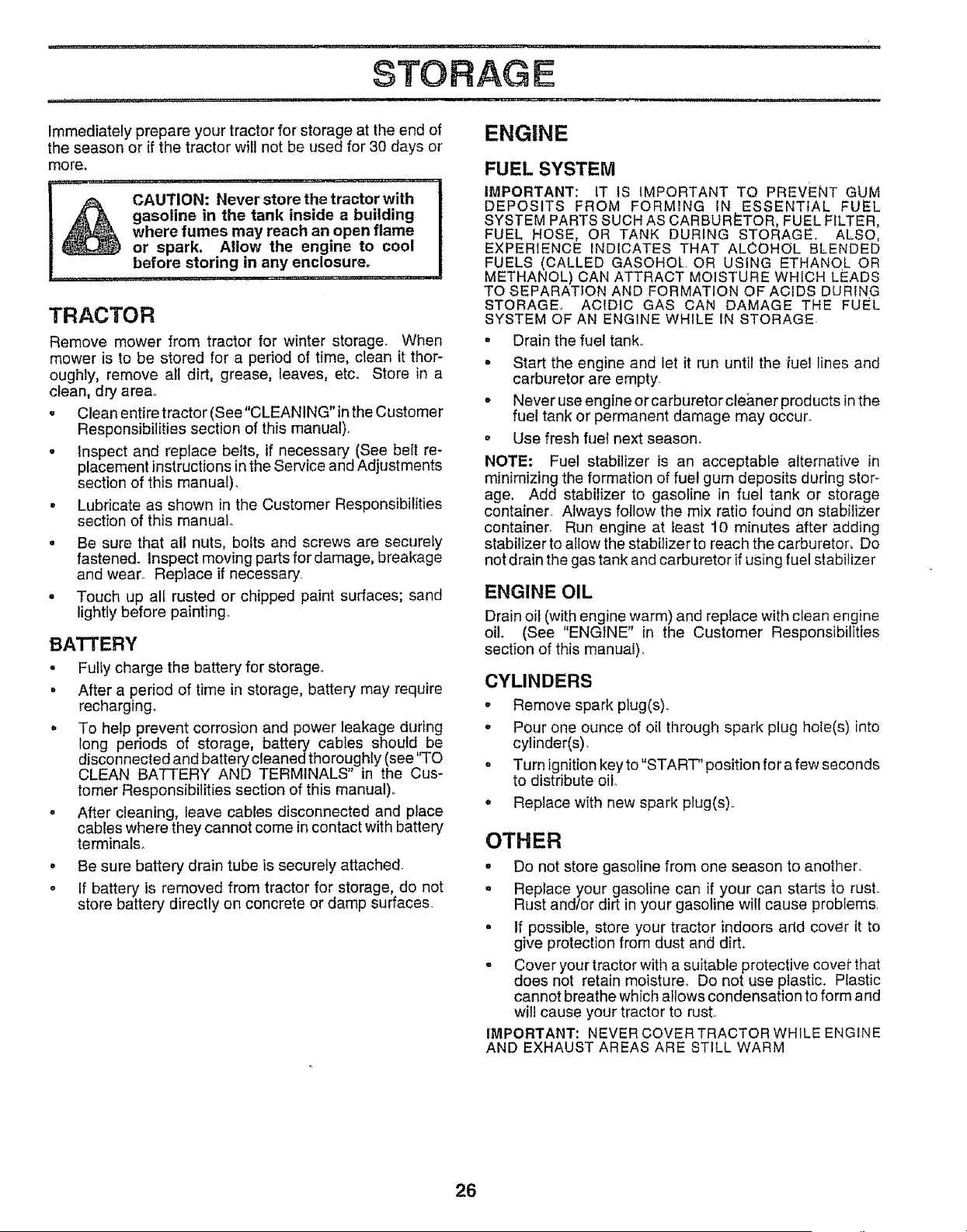
STORAGE
, i,,i, i.......... .
Immediately prepare your tractor for storage at the end of
the season or if the tractor will not be used for 30 days or
more.
.............i ,i....... ,. i i ,.,. i
gasoline in the tank inside a building
where fumes may reach an open flame
or spark. Allow the engine to cool
before storing in any enclosure.
TRACTOR
Remove mower from tractor for winter storage. When
mower is to be stored for a period of time, clean it thor-
oughly, remove all dirt, grease, leaves, etc. Store in a
dean, dry area.
, Clean entire tractor (See"CLEANING" in the Customer
Responsibilities section of this manual)_
• Inspect and replace belts, if necessary (See belt re-
placement instructions in the Service and Adjustments
section of this manual),
- Lubricate as shown in the Customer Responsibilities
section of this manual
• Be sure that all nuts, bolts and screws are securely
fastened, inspect moving partsfordamage, breakage
and wear_ Replace if necessary,
• Touch up all rusted or chipped paint surfaces; sand
lightly before painting,
BATTERY
- Fully charge the battery for storage°
- After a period of time in storage, battery may require
recharging,
= To help prevent corrosion and power leakage during
long periods of storage, battery cables should be
disconnected and battery cleaned thoroughly (see "TO
CLEAN BATTERY AND TERMINALS" in the Cus-
tomer Responsibilities section of this manual).
o After cleaning, leave cables disconnected and place
cables where they cannot come in contact with battery
terminals,,
. Be sure battery drain tube is securely attached.
o If battery is removed from tractor for storage, do not
store battery directly on concrete or damp surfaces.
ENGINE
FUEL SYSTEM
IMPORTANT: IT IS IMPORTANT TO PREVENT GUM
DEPOSITS FROM FORMING IN ESSENTIAL FUEL
SYSTEM PARTS SUCH AS CARBURETOR, FUEL FILTER,
FUEL HOSE, OR TANK DURING STORAGE. ALSO,
EXPERIENCE iNDiCATES THAT ALCOHOL BLENDED
FUELS (CALLED GASOHOL OR USING ETHANOL OR
METHANOL) CAN ATTRACT MOISTURE WHICH LEADS
TO SEPARATION AND FORMATION OF ACIDS DURING
STORAGE, ACIDIC GAS CAN DAMAGE THE FUEL
SYSTEM OF AN ENGINE WHILE IN STORAGE
" Drain the fuel tank.
o Start the engine and let it run until the fuel lines and
carburetor are empty-
- Never use engine or carburetor cte&ner products in the
fuel tank or permanent damage may occur°
,, Use fresh fuel next season.
NOTE: Fuel stabilizer is an acceptable alternative in
minimizing the formation of fuel gum deposits during stor-
age, Add stabilizer to gasoline in fuel tank or storage
container. Always follow the mix ratio fodnd on stabilizer
container, Run engine at least 10 minutes after adding
stabilizer to allow the stabilizer to reach the carburetor, Do
not drain the gas tank and carburetor if using fuel stabilizer
ENGINE OIL
Drain oil (with engine warm) and replace with clean engine
oil. (See "ENGINE" in the Customer Responsibilities
section of this manual),
CYLINDERS
- Remove spark plug(s),.
- Pour one ounce of oil through spark plug hole(s) into
cylinder(s),
= Turn ignition key to "START" position for a few seconds
to distribute oil,,
° Replace with new spark plug(s).
OTHER
. Do not store gasoline from one season to another.
= Replace your gasoline can if your can starts {o rust.
Rust and/or dirt in your gasoline will cause problems,
o If possible, store your tractor indoors arid cover tt to
g_ve protection from dust and dirt.
° Cover your tractor with a suitable protective covel" that
does not retain moisture, Do not use plastic. Plastic
cannot breathe which allows condensation to form and
wilt cause your tractor to rust,.
IMPORTANT: NEVER COVER TRACTOR WHILE ENGINE
AND EXHAUST AREAS ARE STILL WARM
26

TROUBLESHOOTING POINTS
i i i i , iiiii ii
CAUSE CORRECTIONPROBLEM
i i , i,i i ,,i i
Will not start
Hard to start
Engine will not turn over
Engine clicks but will not
start
ii ii ,it i ...........
Loss of power
ii illllll ,ll
Excessive vibration
1 Out of fuel
2, Engine not "CHOKED" properly
3 Engine flooded,
4 Bad spark plug
5 Dtfty air fi{ter
6 Dirty fuel filter,
7 Water in fUet.
8 Loose or damaged wiring
9 Carburetor out of adjustment.
10
Engine valves out of adjL;stment
,i,i i, , ii ,= , i
1 Dirty air filter.
2. Bad spark plug,
3 Weak or dead battery.
4 Dirty rue! filter,
5 Stale or dirty fuel.
6 Loose or damaged wiring,
7 Carburetor out of adjustment
8, Engine valves out of adjustment
1 Clutch'brake pedal not depressed
2 Attachment clutch ls engaged
3 Weak or dead battery,
4 Blown fuse,
5 Corroded battery terminals
6 Loose or damaged wiring
7, Faulty Ignition switch.
8 Faulty solenoid or starter,
9 Faulty operator presence switch(es)o
1 Weak or dead battery,
2 Corroded battery terminals
3. Loose or damaged wtdng
4 Faulty solenoid or starter
1 Cutting too much grass/too fast,
2 Throttle in "CHOKE" position,
3 Build-up of grass, leaves and trash under mower,
4 Dirty air filter,
5 Low of! leveVdirty oil
6 Faulty spark plug,
7 Dirty fuel filter
8 Stale or dirty fuel
9 Water tn fuel,
10 Sparkplug wiretoose,
1t Dirty engine air screentfins
12 Dirty/clogged muffier,
t3 Loose or damaged wiring
14, Carburetor out of adjustment,
t5 Englne valves out of adjustment
1 Worn, bent or loose blade,
2 Bent blade mandrel
3 Loose/damaged part(s),
_ Fill fuel tank
2 See "TO START ENGINE" in Operation section
3 Wait several minutes before attempting to start
4, Replace spark plug,,
5 C|eanireplace air filter
6, Reptace fuet filter
7 Drain fuel tank and carburetor, refilt tank with fresh
gasoline and replace fuel fitter
8 Check all wiring
9 See "To Adjust Carburetor" in Service Adjustments
section
10 Contact an authorized service center/department
1 Clean/replace air filter
2 Replace spark plug,
3 Recharge or replace battery
4 Replace fuel filter
5 Drain fuel tank and refill with fresh gasoline
6 Check all wiring
7 See "To Adjust Carburetor" in Service Adjustments
section
8, Contact an authorized service canter/department
! Depress clutch/brake pedal
2 Disengage attachment clutch,
3 Recharge or replace battery
4 Replace fuse
5 Clean battery terminals,
6, Check all wiring
7 Check/replace ignition switch.
8 Check/replace solenoid or starter
9 Contact _n authorized service center/department
1, Recharge or replace battery
2, Clean battery terminals
3 Check el{ wiring
4 Check/replace solenoid or starter
!, Set in "Higher Cut" position/reduce speed
2 Adjust throttle control
3 Clean underside of mower housing.
4 Clean/replace air _ter
5 Check oil leveVchange oil
6 Clean and regap or change spark plug
7 Replace fuel ii_ter
8, Drain fuel tank and refill with fresh gasoline,
9 Drain fuel tank and carburetor, refill tank with fresh
gasoline and replace fuel filter
10 Connect and fighlen spark plug wire
11, Clean engine air screen/fins
12 Clean/replace muffler
13 Check elf wiring
14 See "To Adjust Carburetor" in Service Adjustments
section
15, Contact an authorized service center/department
1 Reprace blade Tighten blade bolt,
2 Replace biade mandrel.
3, Tighten toose part(s), Replace damaged parts
27
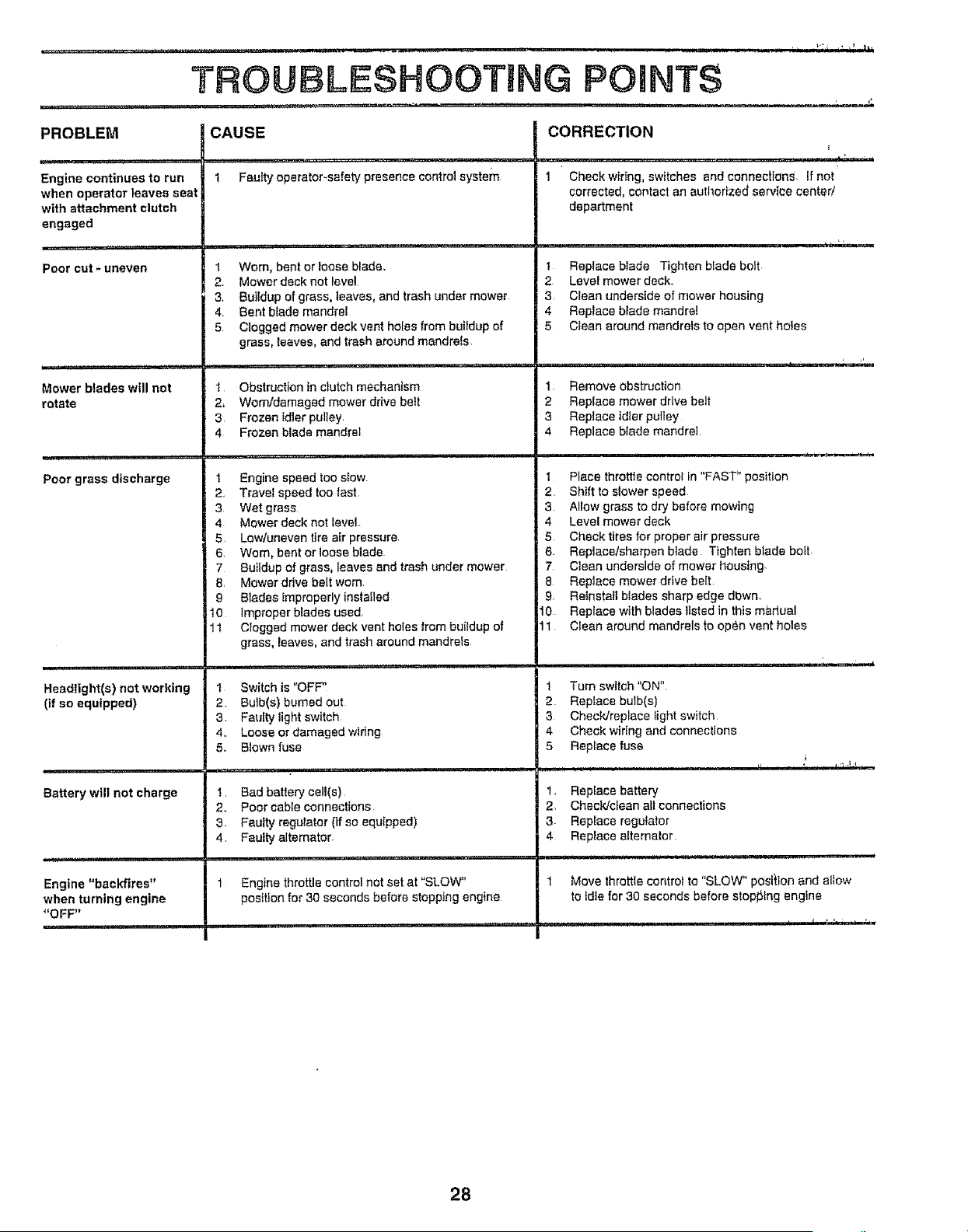
TROUBLESHOOTING POINTS
PROBLEM
......... '""," i 'M"'
Engine continues to run
when operator leaves seat
with attachment clutch
engaged
Poor cut - uneven
i , ii iiii...... i ,, ,
Mower blades will not
rotate
,, I'H
Poor grass discharge
.... i
Headlight(s) not working
(if so equipped)
i
Battery will not charge
Engine "backfires"
when turning engine
"OFF"
CAUSE
,,i ...... ,..............
1 Faults' operator-safety presence control system
1 Worn, bent or loose blade,.
2. Mower deck not level
3, Buildup of grass, leaves, and trash under mower
4 Bent blade mandrel
5 Clogged mower deck vent holes from buildup of
grass, leaves, and trash around msndre{s.
1 Obstruction in clutch mechanism
2, Worn/damaged mower dr_ve be_t
3 Frozen idler pulley
4 Frozen blade mandrel
1 Engine speed tee slew
2, Travel speed too fast
3 Wet grass
4 Mower deck not level
5. Low/uneven tire air pressure,
6, Worn, bent orloose blade
7 Buildup of grass, leaves and trash under mower
8, Mower drive belt worn
9 Blades improperfy installed
I0 improper blades used.
1 t Clogged mower deck vent holes from buildup of
grass, reaves, and trash around mandrels
1 Switch is "OFF"
2 Bulb(s) burned out
3 Faulty light switch
4.. Loose or damaged wiring
5o B!own fuse
I Bad battery celt(s)
2., Poor cable connections
3. Fautty regulator (if so equipped)
4 Faulty alternator.
Engine throttle control not set at "SLOW"
position for 30 seconds before stopping engine
CORRECTION
l
, , I" i ii
1 Check wiring, switches and connecLions if nor
corrected, contact an authorized ssrvt_e center/
department
t Replace blade Tighten blade bolt
2 Level mower deck.
3 Clean underside of mower housing
4 Replace blade mandre!
5 Clean around mandrets to open vent holes
1 Remove obstruction
2 Replace mower drive belt
3 Replace ldter pulley
4 Replace blade mandrel
1 Place throttle controt in "FAST" position
2 Shift toslower speed
3 Allow grass to dry before mowing
4 Level mower deck
5 Checktires for proper air pressure
6. Replace/sharpen blade Tighten blade bolt
7 Clean underside of mower housing
8 Reptace mower drive belt.
9_ Reinstall blades sharp edge dbwn.
10 Replace with blades listed in this mbdual
11 Clean around mandrels to open vent holes
1 Turn switch "ON"
2 Reptace bulb(s)
3 Check/replace light switch
4 Check wiring and connections
5 Replace fuse
i i
1_ Replace battery
2. Chectdcfean all connections
3 Replace regulator
4 Replace affernator.
Move throtlle control to "SLOW" position and allow
to idle for 30 seconds before stopl_lng engine
28
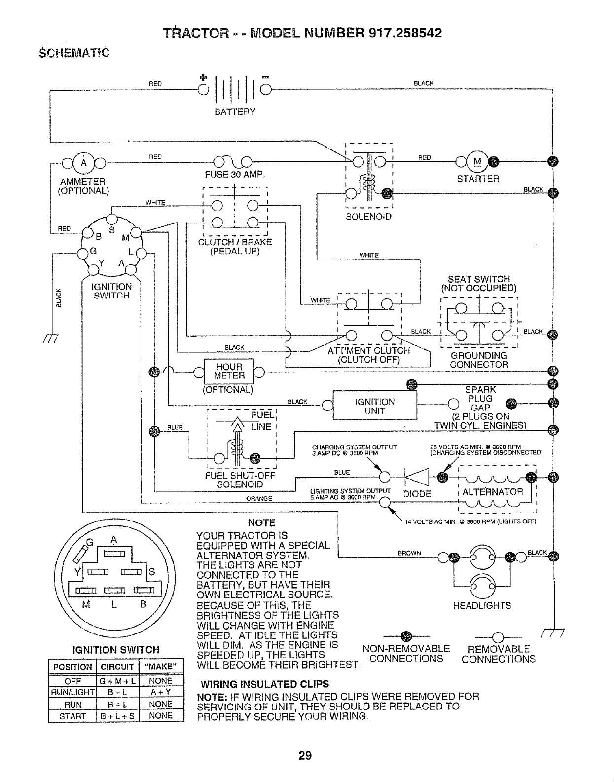
TRACTOR o - r,JIODEL NUMBER 917.258542
SCHE[vIATIC
RED
BATTERY
SLACK
AMMETER
(OPTIONAL)
i ....
RED
WHITE
! I
, { RED
I STARTER
IGNITION
SWITCH
Og,.D
FUSE 30 AMP
r t ....
1 I I
,©',
I
t l
CLUTCH / BRAKE
(PEDAL UP)
BLACK
HOURMETER
SOLENOID
BLACK
(OPTTONAL)
BLACK
r I
I _UELI
L BLUE ', '_.' LINE II
I I
I I
FUEL SHUT-OFF
SOLENOID ,]
ORANGE
IGNITION SWITCH
PoSmON
OFF
RUNILIGHT A + Y
RUN _ NONE
STAR T N ONE
CIRCUIT "MAKE"
G+M+L, NONE
WHITE
SEA,SW,TOH
/.OTOOOUP,ED)
(CLUTCH OFF) ] GROUNDING
CONNECTOR
SPARK
IGNITION _ PLUG
UNIT GAP _-_
PLUGS ON
TWIN CYL ENGINES) _
CHARGING SYS_M OUTPUT
3 AMP DO @ 3600 RPM
BLUE
28 VOLTS AC MIN, @ 3600 RPM
(CHARGING SYSTEM DISCONNECTED)
LIGHT{NG SYSTEM OUTPUT DIODE
5 AMP AO @ 3600 RPM _,_ _._
I j
NOTE 14 VOLTS AC MIN @ 3600 RPM (LIGHTS OFF)
HEADLIGHTS
YOUR TRACTOR 1S
EQUIPPED WITH A SPECIAL
ALTERNATOR SYSTEM.
THE LIGHTS ARE NOT
CONNECTED TO THE
BATTERY, BUT HAVE THEIR
OWN ELECTRICAL SOURCE.
BECAUSE OF THIS, THE
BRIGHTNESS OF THE LIGHTS
W1LL CHANGE WITH ENGINE
SPEED. AT IDLE THE LIGHTS
WiLL DIM. AS THE ENGINE IS
SPEEDED UP, THE LIGHTS
WILL BECOME THEIR BRIGHTEST.
BROWN
B+L
B+L
B+L+s
WIRING INSULATED CLIPS
NON*REMOVABLE REMOVABLE
CONNECTIONS CONNECTIONS
NOTE: tF WIRING INSULATED CLIPS WERE REMOVED FOR
SERVICING OF UNIT, THEY SHOULD BE REPLACED TO
PROPERLY SECURE YOUR WIRING
29
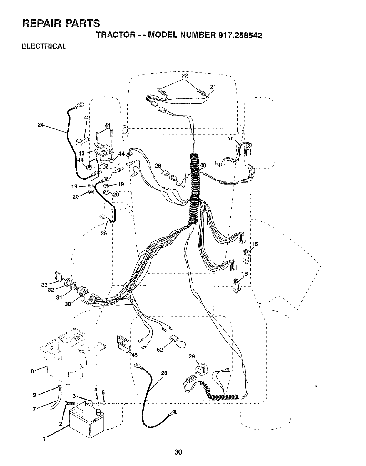
REPAIR PARTS
TRACTOR-- MODEL NUMBER 917.258542
ELECTRICAL
21
/
I
I
70
9
7
33
19
20
25
26
1
52
29
' _ 28 /
1
3O
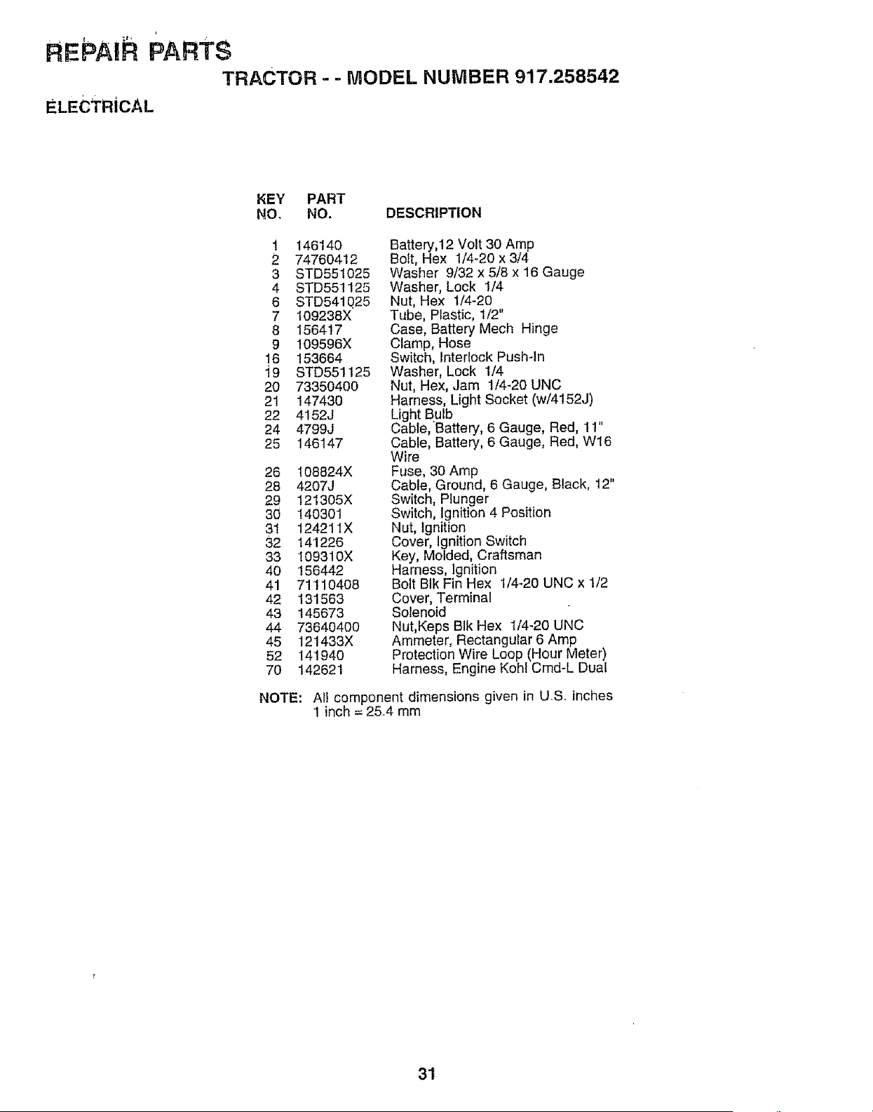
F EPA hPARTS
TRACTOR- - MODEL NUMBER 917.258542
ELECTRICAL
KEY PART
NO, NO, DESCRIPTION
1 146140
2 74760412
3 STD551025
4 STD551125
6 STD541Q25
7 109238X
8 156417
9 109596X
16 153664
i9 STD551125
20 73350400
21 147430
22 4152J
24 4799J
25 146147
26 108824X
28 4207J
29 121305X
30 140301
31 12421tX
32 141226
33 109310X
40 156442
41 71110408
42 131563
43 145673
44 73640400
45 121433X
52 141940
70 142621
Battery,12 Volt 30 Amp
Bo_t,Hex t/4-20 x 3/4
Washer 9/32 x 5/8 x 16 Gauge
Washer, Lock 1/4
Nut, Hex t/4-20
Tube, Plastic, t/2"
Case, Battery Mech Hinge
Clamp, Hose
Switch, Interlock Push-in
Washer, Lock 1/4
Nut, Hex, Jam 1/4-20 UNC
Harness, Light Socket (w/4152J)
Light Bulb
Cable, Battery, 6 Gauge, Red, 11"
Cable, Battery, 6 Gauge, Red, W16
Wire
Fuse, 30 Amp
Cable, Ground, 6 Gauge, Black, 12"
Switch, Plunger
Switch, Ignition 4 Position
Nut, Ignition
Cover, Ignition Switch
Key, Molded, Craftsman
Harness, Ignition
Bolt BIk Fin Hex t/4_20 UNC x 1/2
Cover, Terminal
Solenoid
Nut,Keps BIk Hex 1/4-20 UNC
Ammeter, Rectangular 6 Amp
Protection Wire Loop (Hour Meter)
Harness, Engine KeN Cmd-L Duaf
NOTE: Ail component dimensions given in USo inches
1 inch = 25,4 mm
31
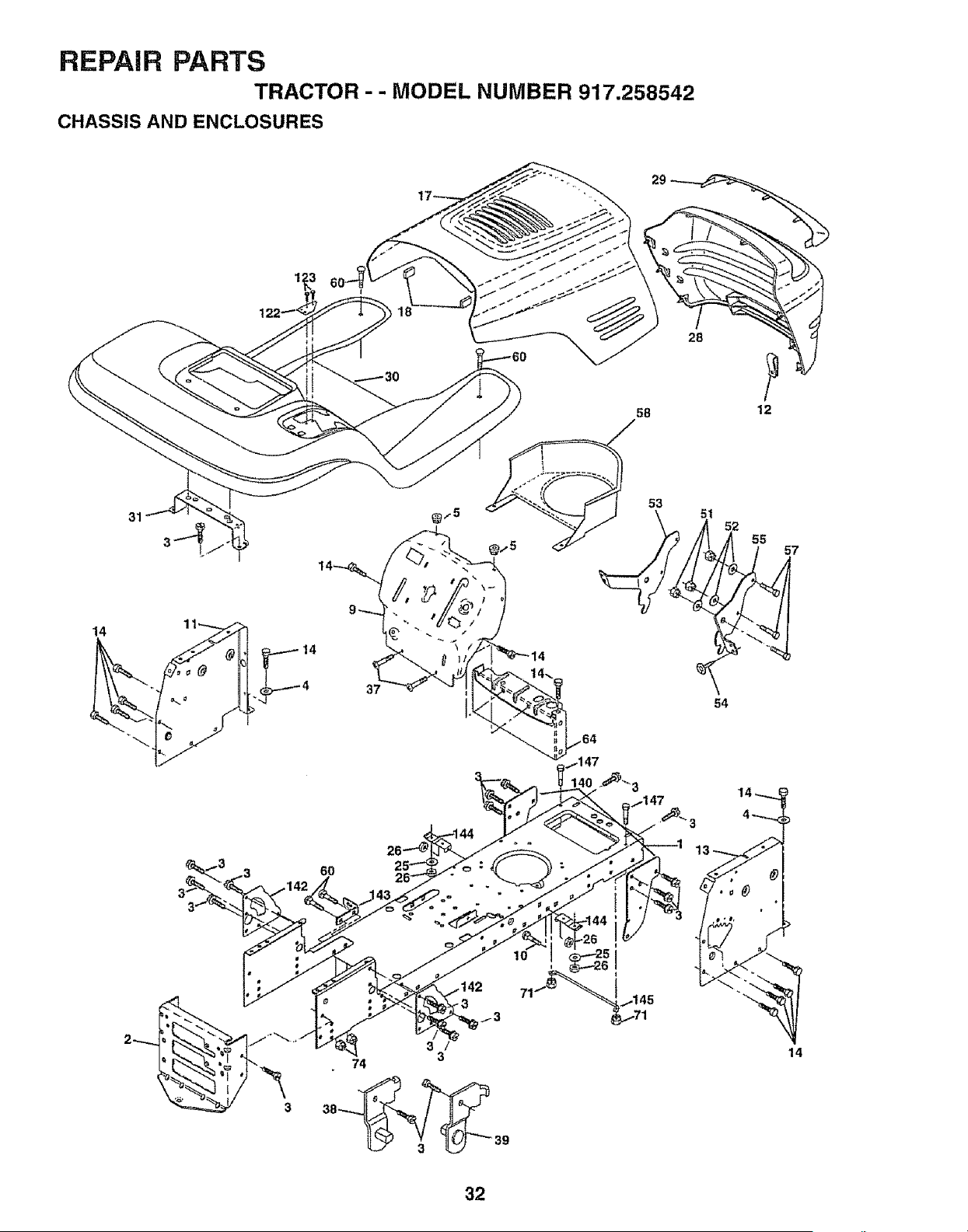
REPAIR PARTS
TRACTOR - - MODEL NUMBER 917.258542
CHASSIS AND ENCLOSURES
29
58
53
28
12
52
55
57
14 11_
37
54
6O
3
3
74
+
38_ 3_ 39
71
14
32
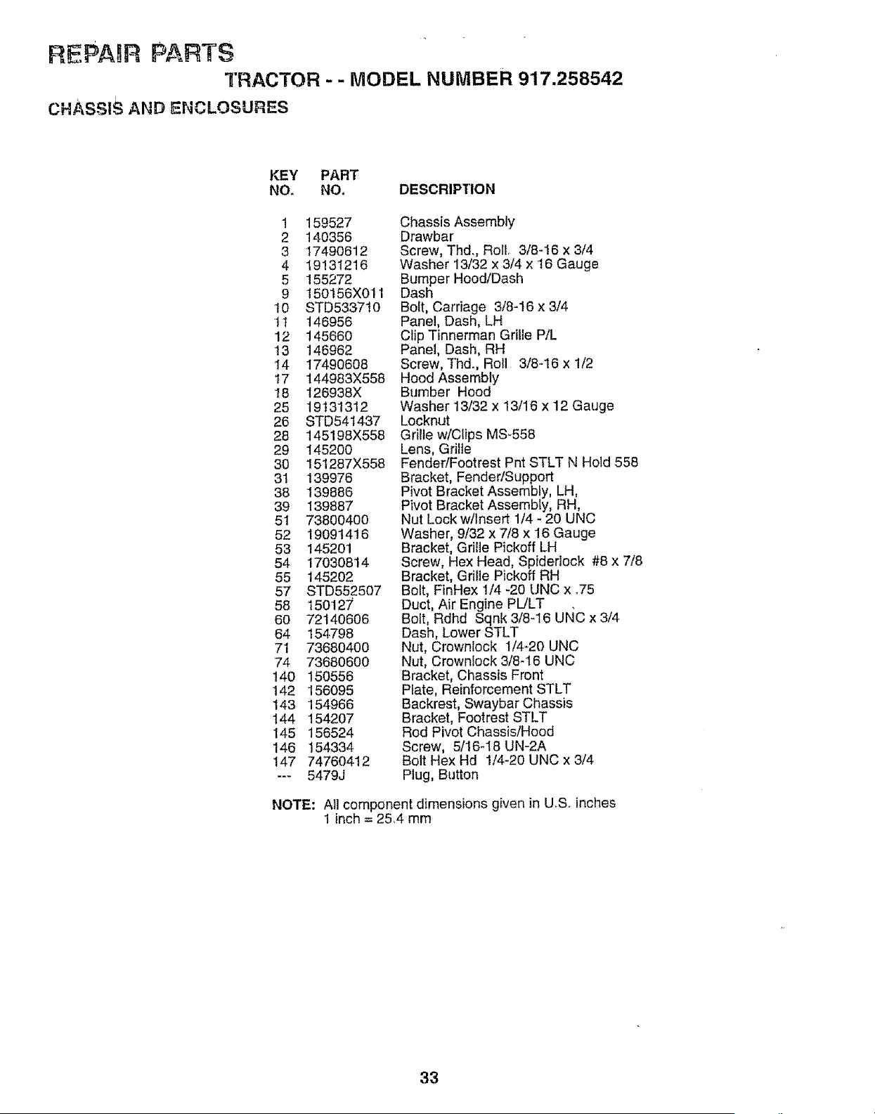
IREPAIR PARTS
TRACTOR - - MODEL NUMBER 917.258542
CHASS1SANDENCLOSURES
KEY PART
NO. NO.
DESCRIPTION
1 159527
2 140356
3 17490612
4 19131216
5 155272
9 150156X011
10 STD5337t0
1t 146956
12 145660
!3 146962
14 17490608
I7 144983X558
18 I26938X
25 19131312
26 STD54t437
28 145198X558
29 145200
30 151287X558
31 139976
38 139886
39 139887
51 73800400
52 19091416
53 145201
54 17030814
55 145202
57 STD552507
58 150127
60 72140606
64 154798
71 73680400
74 73680600
140 150556
142 156095
143 154966
144 154207
145 156524
146 154334
147 74760412
--_ 5479J
Chassis Assembly
Drawbar
Screw, Thd., Roll, 3/8-!6 x 3/4
Washer 13/32 x 3/4 x 16 Gauge
Bumper Hood/Dash
Dash
Bolt, Carriage 3/8-16 x 3/4
Panel, Dash, LH
Clip Tinnerman Grille P/L
Panel, Dash, RH
Screw, Thd., Roll 3/8-16 x 1/2
Hood Assembly
Bumber Hood
Washer 13/32 x 13/16 x 12 Gauge
Locknut
Grille w/Clips MS-558
Lens, Grille
Fender/Footrest Pnt STLT N Hold 558
Bracket, Fender/Support
Pivot Bracket Assembly, LH,
Pivot Bracket Assembly, RH,
Nut Lock w/Insert 1/4 - 20 UNC
Washer, 9/32 x 7/8 x 16 Gauge
Bracket, Grille Pickoff LH
Screw, Hex Head, Spidedock #8 x 7/8
Bracket, Grille Pickoff RH
Bolt, FinHex 1/4 -20 UNC x .75
Duct, Air Engine PL/LT
Bolt, Rdhd Sqnk 3/8-16 UNC x 3/4
Dash, Lower STLT
Nut, Crownlock t/4-20 UNC
Nut, Crownlock 3/8-16 UNC
Bracket, Chassis Front
Plate, Reinforcement STLT
Backrest, Swaybar Chassis
Bracket, Footrest STLT
Rod Pivot Chassis/Hood
Screw, 5/16-18 UN-2A
Bolt Hex Hd 1/4-20 UNC x 3/4
Plug, Button
NOTE: All component dimensions given in U_S,,inches
1 inch = 25,4 mm
33
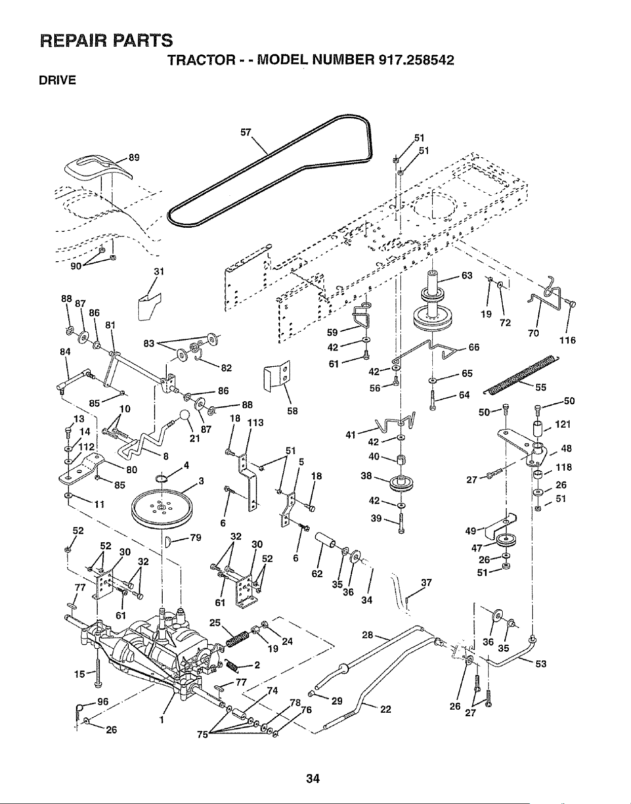
REPAIR PARTS
TRACTOR . . MODEL NUMBER 917.258542
DRIVE
89
31
88 87
86
81
84
83 _82
86
18 113
87
21
75
61
58
!9
51
5
18
116
I 121
ti 48
1t8
26
5t
t
27
34
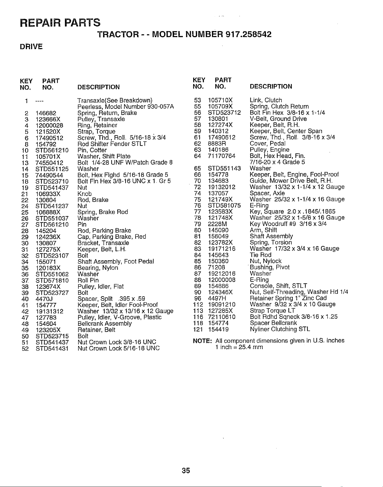
REPAIR PARTS
TRACTOR - - MODEL NUMBER 917.258542
DRIVE
KEY PART KEY PART
NO. NO. DESCRIPTION NO. NO. DESCRIPTION
1 .... Transaxle(See Breakdown) 53 105710X
Peerless, Model Number 930-057A 55 105709X
2 146682 Spring, Return, Brake 56 STD523712
3 123666X PuItey, Transaxte 57 130801
4 12000028 Ring, Retainer 58 127274X
5 12!520X Strap, Torque 59 140312
6 17490512 Screw, Thd., Roll. 5/16-18 x 3/4 61 17490612
8 154792 Rod Shifter Fender STLT 62 8883R
10 STD561210 Pin, Cotter 63 140186
11 105701X Washer, Shift Plate 64 7'1170764
13 74550412 Bolt 1/4-28 UNF W/Patch Grade 8
14 STD551125 Washer 65 STD551143
15 74490544 Bolt, Hex FIghd 5/16_18 Grade 5 66 154778
18 STD523710 Bolt Fin Hex 3/8-16 UNC x 1. Gr 5 70 134683
19 STD541437 Nut 72 19132012
2t 106933X Knob 74 137057
22 130804 Rod, Brake 75 121749X
24 STD54t237 Nut 76 STD581075
25 106888X Spring, Brake Red 77 123583X
26 STD55t037 Washer 78 121748X
27 STD561210 Pin 79 2228M
28 145204 Rod, Parking Brake 80 145090
29 124236X Cap, Parking Brake, Red 81 156049
30 130807 Bracket, Transaxle 82 123782X
31 127275X Keeper, Belt, LoH 83 19171216
32 STD523107 Bolt 84 145643
34 15507t Shaft Assembly, Foot Pedal 85 150360
35 !20183X Bearing, Nylon 86 71208
36 STD551062 Washer 87 19212016
37 STD571810 Roll Pin 88 12000008
38 123674X Pulley, Idler, Flat 89 154886
39 STD523727 Bolt 90 124346X
40 4470J Spacer, Split _395x _59 96 4497H
41 '154777 Keeper, Belt, IdlerFoot-Proof 112 19091210
42 19131312 Washer 13/32 x 13/16 x 12 Gauge 113 127285X
47 127783 Pulley, Idler, V-Groove, Plastic 116 72110610
48 154604 Beltcrank Assembty 118 154774
49 123205X Retainer, Belt 121 154419
50 STD523715 Bolt
51 STD541437 Nut Crown Lock 3/8-16 UNC
52 STD541431 Nut Crown Lock 5/16-18 UNC
Link, Clutch
Spring, Clutch Return
Bolt Fin Hex 3/8-16 x tq/4
V-Belt, Ground Drive
Keeper, Belt, R_H.
Keeper, Beit, Center Span
Screw, Thd., Rail. 3/8-16 x 3/4
Cover, Pedal
Pulley, Engine
Bolt, Hex Head, Fin,
7/16-20 x 4 Grade 5
Washer
Keeper, Belt, Engine, Fool-Proof
Guide, Mower Drive Belt, R_H.
Washer 13/32 x 1-1/4 x t2 Gauge
Spacer, Axle
Washer 25/32 x 1-1/4 x 16 Gauge
E-Ring
Key, Square 2_0 x .1845/.1865
Washer 25/32 x 1-5/8 x 16 Gauge
Key Woodruff #9 3/16 x 3/4
Arm, Shift
Shaft Assembly
Spring, Torsion
Washer 17/32 x 3/4 x 16 Gauge
Tie Rod
Nut, Nylock
Bushing, Pivot
Washer
E-Ring
Console, Shift, STLT
Nut, Self-Threading, Washer Hd 1/4
Retainer Spring 1" Zinc Cad
Washer 9/32 x 3/4 x 10 Gauge
Strap Torque LT
Bolt Rdhd Sqneck 3/8-16 x 1.25
Spacer Bellcrank
Nyliner Clutching STL
NOTE: All component dimensions given in U.S. inches
1 inch = 2&4 mm
35
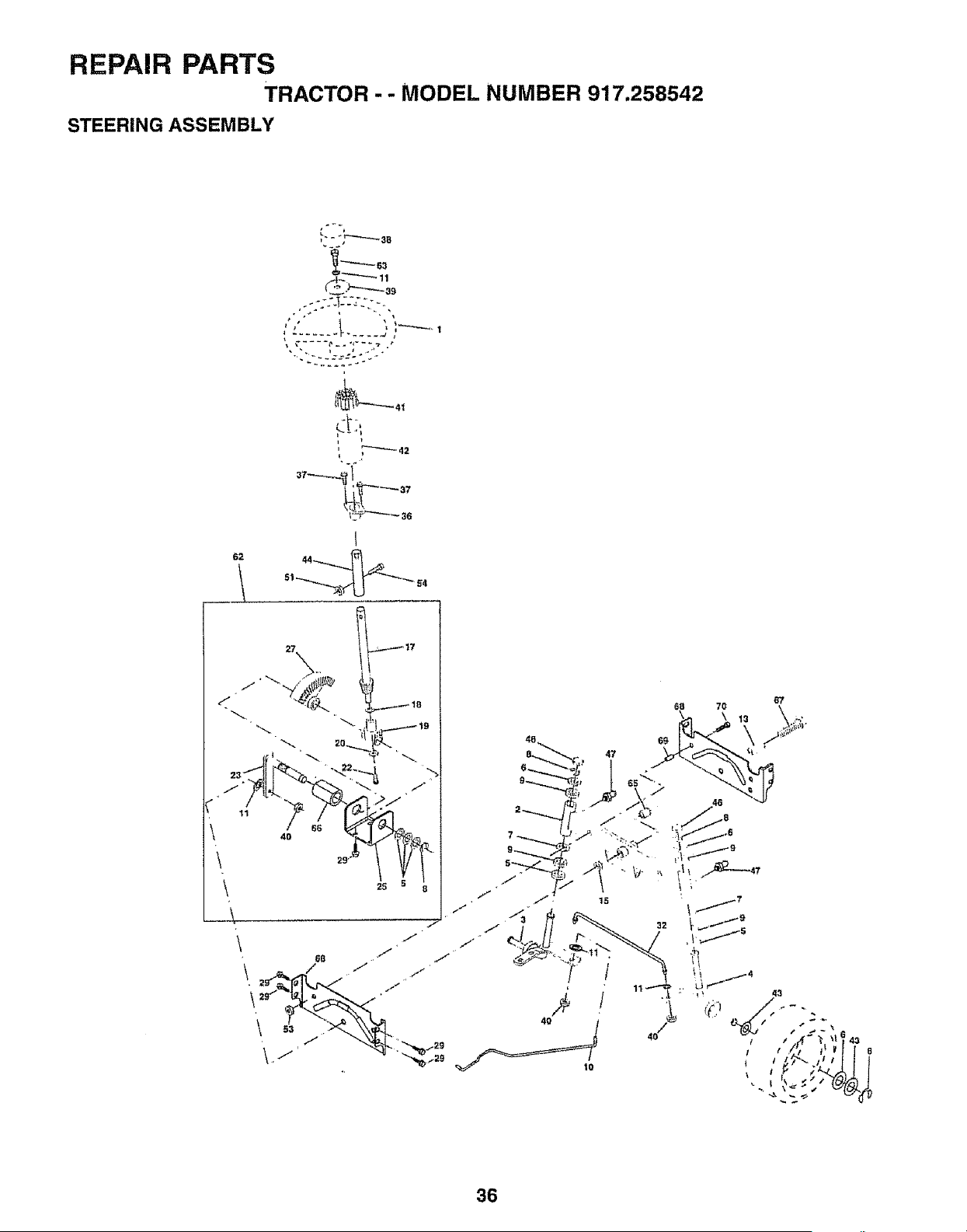
REPAIR PARTS
TRACTOR - -
STEERING ASSEMBLY
MODEL NUMBER 917.258542
_L"T _'_ 11
i
i
51 _ 54
_'X _ 17
" 7' FF_2_
/ _ " I / ,,_.,_?
f
\ 1"
68 ,/
J
\1 ! -.%:_:
J
./"
40
36
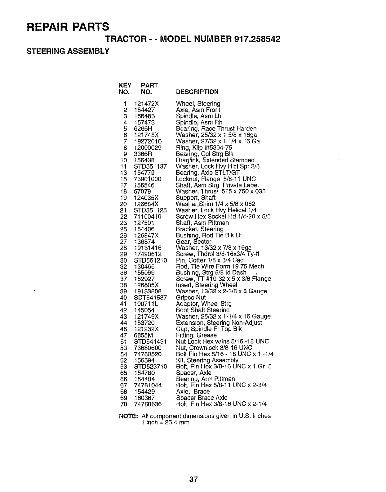
REPAIR PARTS
TRACTOR - - MODEL NUMBER 917.258542
STEERING ASSEMBLY
KEY PART
NO. NO. DESCRIPTION
1 121472X
2 154427
3 156483
4 157473
5 6266H
6 121748X
7 I9272016
8 12000029
9 3366R
10 i56438
11 STD551137
13 154779
15 73901000
17 156546
18 57079
19 ]24035X
20 126684X
2t STD551125
22 711004t0
23 127501
25 154406
26 126847X
27 136874
28 19131416
29 t7490612
30 STD561210
32 130465
36 155099
37 152927
38 t26805X
39 19133808
40 SDT541537
41 100711L
42 145054
43 121749X
44 153720
46 121232X
47 6855M
51 8TD541431
53 73680600
54 74780520
62 156594
63 STD523710
65 I54780
66 154404
67 74781044
68 154429
69 160367
70 74780636
Wheel, Steering
Axle, Asm Front
Spindle, Asm Lh
Spindle, Asm Rh
Bearing, Race Thrust Harden
Washer, 25/32 x 1 5/8 x 16ga
Washer, 27/32 x 1 1/4 x 16 Ga
Ring, Klip #t5304-75
Bearing, Cot Strg Btk
Draglink, Extended Stamped
Washer, Lock Hvy Hlcl Spr 3/8
Bearing, Axle STLT!GT
Locknut, Flange 5/8-11 UNC
Shaft, Asm Strg Private Label
Washer,, Thrust 515 x 750 x 033
Support, Shaft
Washer, Shim 1/4 x 5/8 x 062
Washer, Lock Hvy Helical 1/4
Screw,Hex Socket Hd 1/4-20 x 5/8
Shaft, Asm Pittman
Bracket, Steering
Bushing, Rod Tie Bik Lt
Gear, Sector
Washer, 13/32 x 7/8 x 16ga
Screw, Thdrol 3/8-16x3/4 Ty-tt
Pin, Cotter 1/8 x 3/4 Cad
Rod, Tie Wire Form t9 75 Mech
Bushing, Strg 5/8 Id Dash
Screw, TT #10o32 x 5 x 3/8 Fiange
Insert, Steering Wheel
Washer, 13/32 x 2-3/8 x 8 Gauge
Gripco Nut
Adaptor, Wheel Strg
Boot Shaft Steering
Washer, 25/32 x 1-1/4 x 16 Gauge
Extension, Steering Non-Adjust
Cap, Spindle Fr Top Blk
Fitting, Grease
Nut Lock Hex w/Ins 5/16 -18 UNC
Nut, Crownleck 3/8_16 UNC
Bolt Fin Hex 5/16 - t8 UNC x 1 -1/4
Kit, Steering Assembly
Bolt, Fin Hex 3/8-16 UNC x 1 Gr 5
Spacer, Axle
Bearing, Arm Pittman
Bolt, Fin Hex 5/8_11 UNC x 2_3/4
Axle, Brace
Spacer Brace Axle
Bolt Fin Hex 3/8-16 UNC x 2_1/4
NOTE: All component dimensions given in U.S, inches
1 inch = 25.4 mm
37
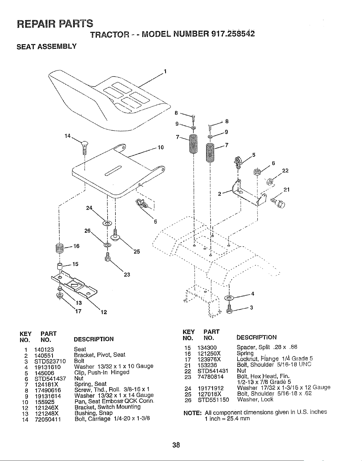
REPAIR PARTS
TRACTOR .- - MODEL NUMBER 917,258542
SEAT ASSEMBLY
V°
j..,5
6 22
21
,/
KEY
NO.
1
2
3
4
5
6
7
8
9
10
12
13
14
PART
NO.
140123
140551
STD523710
19131610
145006
STD541437
124181X
17490616
191316't4
155925
121246X
121248X
72050411
DESCRIPTION
Seat
Bracket, Pivot, Seat
Bolt
Washer 13/32 x 1 x 10 Gauge
Clip, Push-In Hinged
Nut
Spring, Seat
Screw, Thd., Roll. 3/8-16 x 1
Washer 13/32 x I x 14 Gauge
Pan, Seat Embos_ QCK Conn.
Bracket, Switch Mounting
Bushing, Snap
Bolt, Carriage 1/4-20 x 1-3/8
KEY PART
NO. NO. DESCRIPTION
15 134300
16 121250X
17 123976X
21 153236
22 STD541431
23 74780814
24 '19171912
25 127018X
26 STD55t150
Spader, Split ,28 x .88
Spring ,
LocknUt, i=lange 1/4 Glade 5
Bolt, ShOulder 5/!6-18 UNC
Nut
BOlt, Hex ,Head, Fin.
I/2-13 x "//8 Grad_ 5
WaSher t7/32 X 1-3/16 x 12 Gauge
Bolt, Shoulder 5/t6-t8 x 62
Washer, LOoR
NOTE: All component dimensions given in U.S. ir_ches
1 inch = 25.4 mm
38
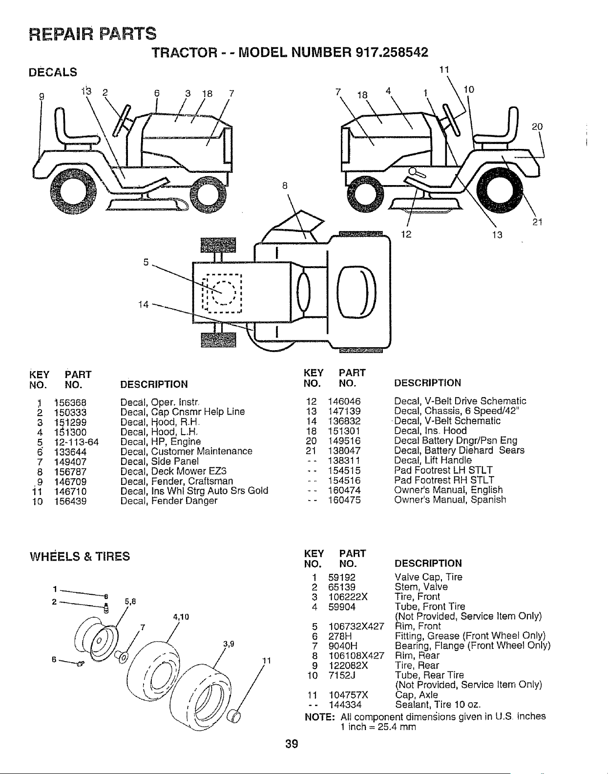
REPAIR PARTS
TRACTOR - - MODEL NUMBER 917.258542
DECALS
9
1_ 2 6 3 18 7
7 18
14
11
10
12 13
2O
21
t
KEY PART
NO. NO.
,1 156368
2 t50333
3 151299
4 151300
5 12-113-64
6" 133644
7 149407
8 156787
.9 146709
11 146710
10 156439
DESCRIPTION
Decal
Decal
Decal
Decal
Decal
Decal
Decal
Decal
Decal
Decal
Decal,
KEY PART
NO. NO.
Oper. Instr. 12 146046
Cap Cnsmr Hetp Line 13 147139
Hood, R.H. 14 136832
Hood, L.H. 18 151301
HP, Engine 20 149516
Customer Maintenance 21 138047
Side Panel - - 13831 t
Deck Mower EZ3 - - 154515
Fender, Craftsman -.- 154516
Ins Whl Strg Auto Srs Gold - - 160474
Fender Danger _- 160475
DESCRIPTION
Decal, V-Belt Drive Schematic
Decal, Chassis, 6 Speed/42"
•Decal, V-Belt Schematic
Decal, Ins_ Hood
Decal Battery Dngr/Psn Eng
Decal, Battery Diehard Sears
Decal, Lift Handle
Pad Footrest LH STLT
Pad Footrest RH STLT
Owner's Manual, English
Owner's Manual, Spanish
WHEELS & TIRES
4,10
11
39
KEY PART
NO, NO.
1 59192
2 65139
3 106222X
4 59904
5 106732X427
6 278H
7 9040H
8 106108X427
9 122082X
10 7152J
11 104757X
-- 144334
DESCRIPTION
Valve Cap, Tire
Stem, Valve
Tire, Front
Tube, Front Tire
(Not Provided, Service Item Only)
Rim, Front
Fitting, Grease (Front Wheel Only)
Bearing, Flange (Front Wheel Only)
Rim, Rear
Tire, Rear
Tube, Rear Tire
(Not Provided, Service item Only)
Cap, Axle
Sealant, Tire 10 oz..
NOTE: All component dimensions given in U.S inches
1 inch = 25,4 mm
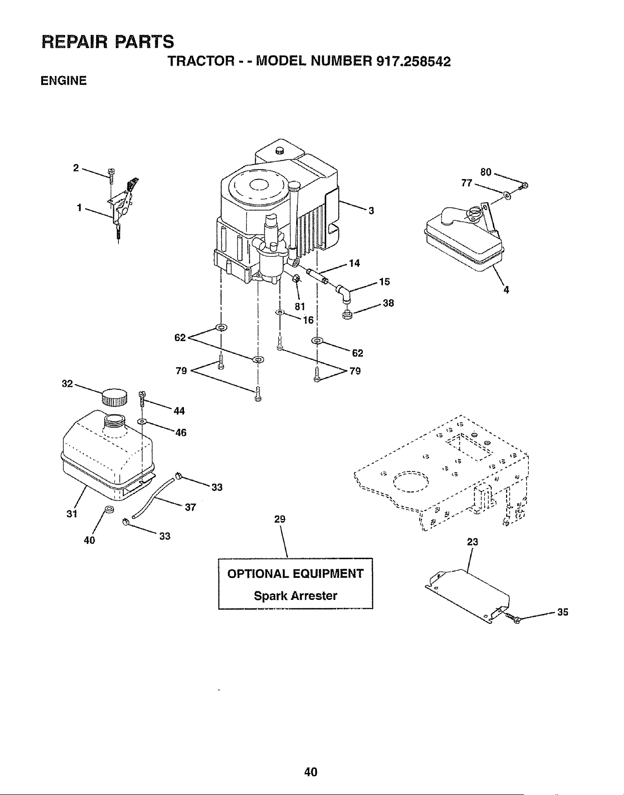
REPAIR PARTS
TRACTOR - - MODEL NUMBER 917.258542
ENGINE
33
"33
37
29
OPTIONAL EQUIPMENT
Spark Arrester
4
23
35
40
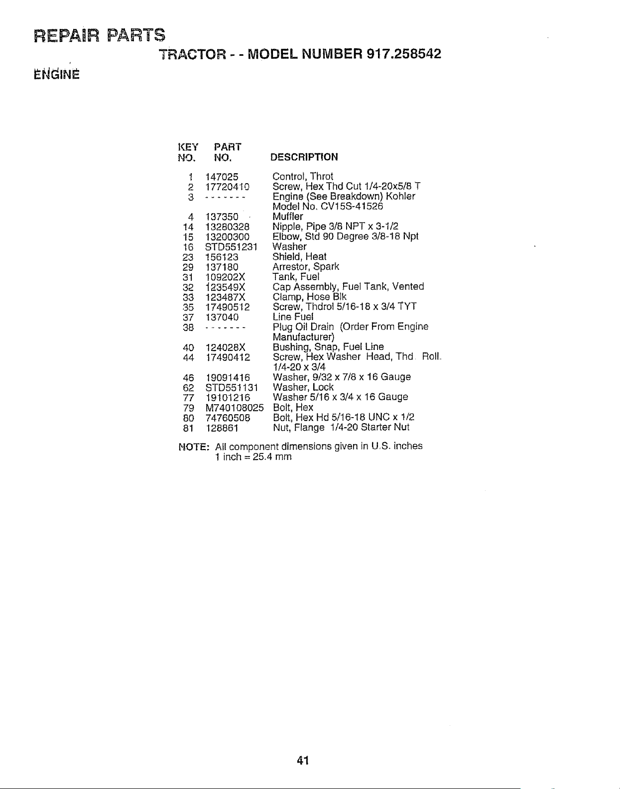
REPAmR PARTS
TRACTOR- - MODEL NUMBER 917.258542
KEY PART
NO. NO. DESCRIPTION
1
2
3
147025
17720410
4 137350
14 13280328
15 13200300
16 STD551231
23 156123
29 137180
31 109202X
32 _23549X
33 123487X
35 17490512
37 137040
38
40 124028X
44 17490412
46 19091416
62 STD551131
77 19t01216
79 M740108025
80 74760508
81 128861
Control, Throt
Screw, Hex Thd Cut 1/4-20x5/8 T
Engine (See Breakdown) Kohler
Model NOoCV15S-41526
Muffler
Nipple, Pipe 3/8 NPT x 3-1/2
Etbow, Std 90 Degree 3/8-t8 Npt
Washer
Shield, Heat
Arrestor, Spark
Tank, Fuel
Cap Assembly, Fuel Tank, Vented
Clamp, Hose Blk
Screw, Thdrol 5/16-18 x 3/4 TYT
Line Fuel
Plug Oil Drain (Order From Engine
Manufacturer)
Bushing, Snap, Fuel Line
Screw, Hex Washer Head, Thd Roll,,
1/4-20 x 3/4
Washer, 9/32 x 7/8 x 16 Gauge
Washer, Lock
Washer 5/16 x 3/4 x 16 Gauge
Bolt, Hex
Bolt, Hex Hd 5/16-18 UNC x 1/2
Nut, Flange 1/4-20 Starter Nut
NOTE: All component dimensions given in US. inches
1 inch = 25.4 mm
41
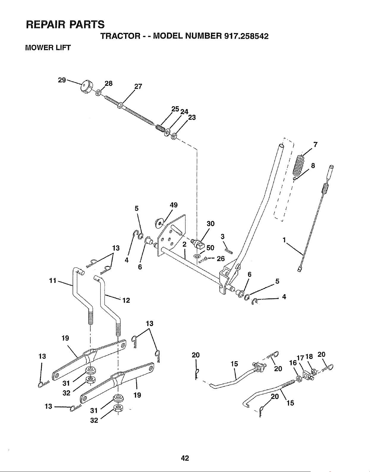
REPAIR PARTS
TRACTOR -- MODEL NUMBER 917.258542
MOWER LIFT
27
25 24
23
5 49
6
3O
150
26
3
\
6
19
13
19
2O
15
._G 161718 20
20
42
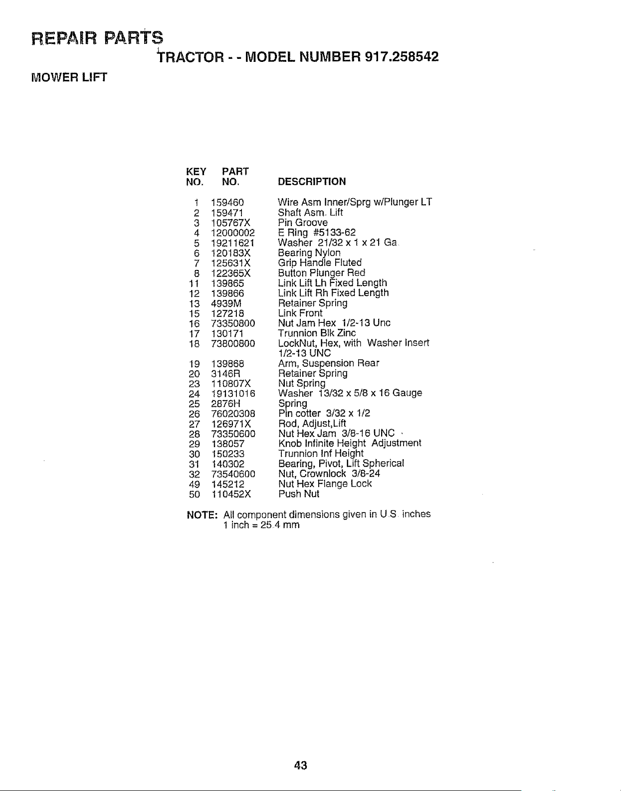
REPAIR PARTS
tRACTOR - - MODEL NUMBER 917.258542
MOWER LIFT
KEY PART
NO. NO, DESCRIPTION
I 159460
2 159471
3 105767X
4 12OO0002
5 19211621
6 120183X
7 125631X
8 122365X
11 139865
12 139866
13 4939M
15 127218
16 73350800
17 130171
18 73800800
19 139868
20 3146R
23 110807X
24 19131O16
25 2876H
26 76020308
27 126971X
28 73350600
29 138057
30 150233
31 140302
32 73540600
49 145212
50 110452X
Wire Asm Inner/Sprg w/Plunger LT
Shaft Asm Lift
Pin Groove
E Ring #5133-62
Washer 21/32 x I x 21 Ga
Bearing Nylon
Grip Handle Fluted
Button Plunger Red
Link Lift Lh Fixed Length
Link Lift Rh Fixed Length
Retainer Spring
Link Front
Nut Jam Hex 1/2-13 Unc
Trunnion Bik Zinc
LockNut, Hex, with Washer insert
1/2_13 UNC
Arm, Suspension Rear
Retainer Spring
Nut Spring
Washer 13/32 x 5/8 x 16 Gauge
Spring
Pin cotter 3/32 x 1/2
Rod, Adjust,Lift
Nut Hex Jam 3/8-16 UNC ,
Knob Infinite Height Adjustment
Trunnion inf Height
Bearing, Pivot, Lift Spherical
Nut, Crownlock 3/8-24
Nut Hex Flange Lock
Push Nut
NOTE: All component dimensions given in U S inches
1 inch = 254 mm
43
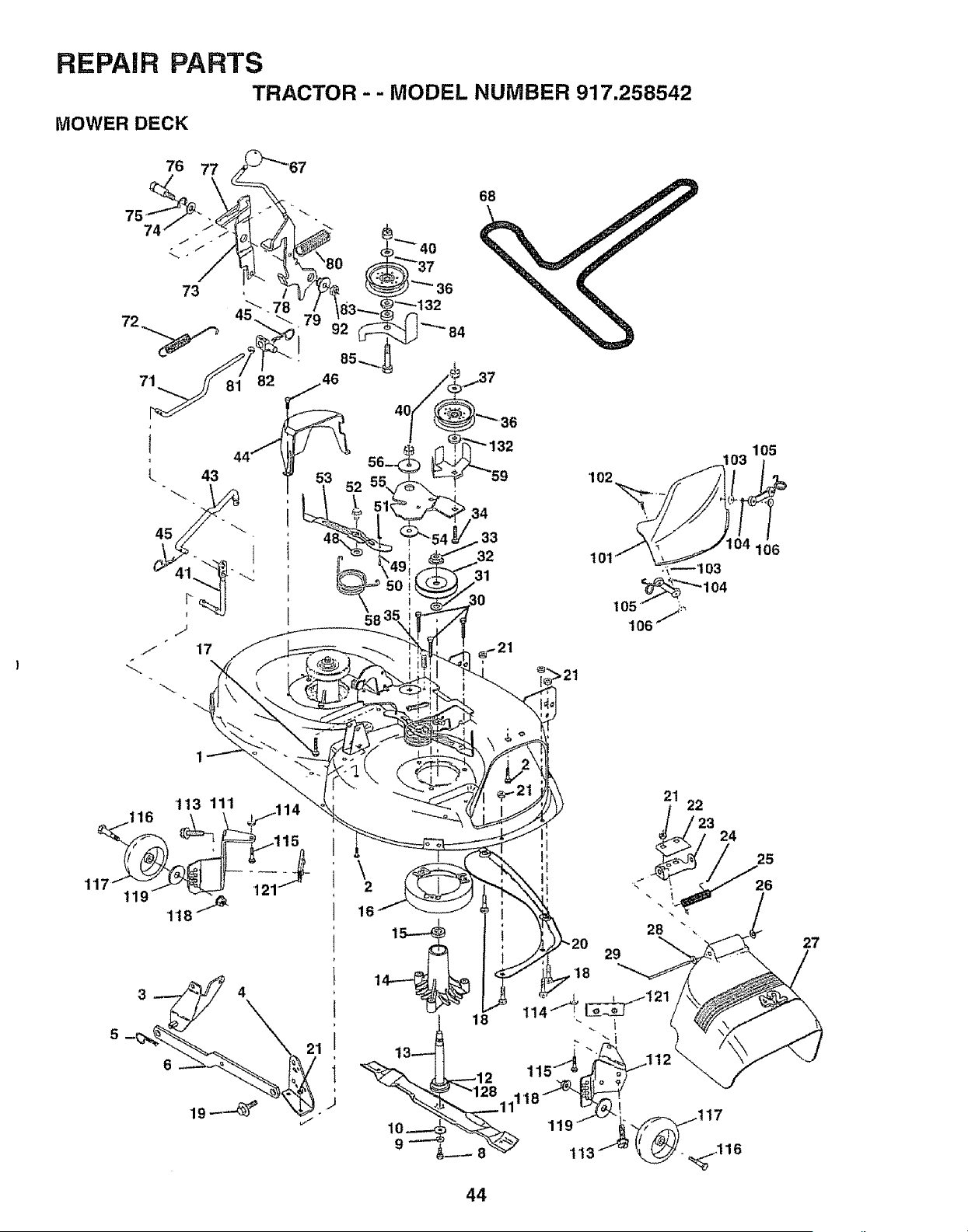
REPAIR PARTS
TRACTOR - - MODEL NUMBER 917.258542
MOWER DECK
76
31
105
106
113 111 114
116 _
1,18_._ "
\
2
16
44
29
21
i
22
24
17
,_116
25
26
27
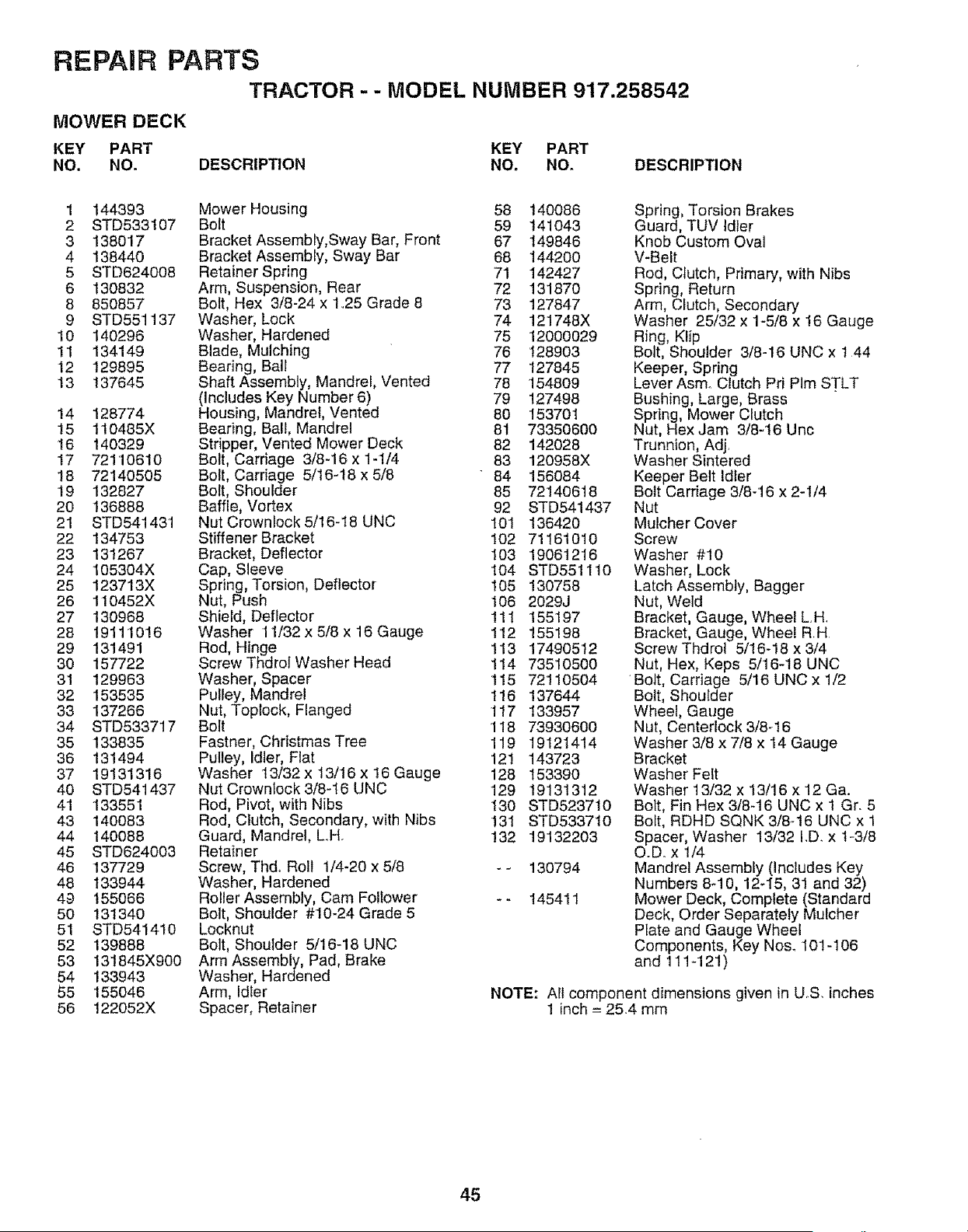
REPAIR PARTS
TRACTOR - - MODEL NUMBER 917.258542
MOWER DECK
KEY PART
NO, NO.
KEY PART
DESCRIPTION NO. NO. DESCRIPTION
1 144393
2 STD533107
3 138017
4 138440
5 STD624008
6 130832
8 850857
9 STD551137
10 140296
11 134149
12 129895
13 137645
14 128774
15 110485X
16 140329
17 72110610
18 72140505
19 132827
20 136888
21 STD541431
22 134753
23 131267
24 105304X
25 123713X
26 110452X
27 130968
28 19111016
29 131491
30 157722
31 129963
32 153535
33 137266
34 STD533717
35 133835
36 131494
37 19131316
40 STD541437
41 133551
43 140083
44 140088
45 STD624003
46 137729
48 133944
49 155066
50 131340
51 STD541410
52 139888
53 13t845X900
54 133943
55 155046
56 122052X
Mower Housing 58
Bolt 59
Bracket Assembly,Sway Bar, Front 67
Bracket Assembly, Sway Bar 68
Retainer Spring 71
Arm, Suspension, Rear 72
Bolt, Hex 3/8-24 x 1..25 Grade 8 73
Washer, Lock 74
Washer, Hardened 75
Blade, Mulching 76
Bearing, Ball 77
Shaft Assembly, Mandrel, Vented 78
(Includes Key Number 6) 79
Housing, Mandrel, Vented 80
Bearing, Ball, Mandrel 81
Stripper, Vented Mower Deck 82
Bolt, Carriage 3/8-16 x 1-1/4 83
Bolt, Carriage 5/16-t8 x 5/8 * 84
Bolt, Shoulder 85
Baffle, Vortex 92
Nut Crownlock 5/16-18 UNC 101
Stiffener Bracket 102
Bracket, Deflector 103
Cap, Sleeve 104
Spring, Torsion, Deflector 105
Nut, Push 106
Shield, Deflector 111
Washer 11/32 x 5/8 x 16 Gauge 1t2
Rod, Hinge 113
Screw Thdrol Washer Head 114
Washer, Spacer 115
Pulley, Mandrel 1!6
Nut, Toplock, Flanged 117
Bolt 1I8
Fastner, Christmas Tree 119
Pulley, Idler, Flat 121
Washer 13/32 x 13/t6 x 16 Gauge 128
Nut Crownlock 3/8-16 UNC 129
Rod, Pivot, with Nibs 130
Rod, Clutch, Secondary, with Nibs 131
Guard, Mandrel, L_H. !32
Retainer
Screw, Thdo Roll 1/4-20 x 5/8 - -
Washer, Hardened
Roller Assembly, Cam Foltower *.
Bolt, Shoulder #10-24 Grade 5
Locknut
Bolt, Shoulder 5/16-18 UNC
Arm Assembly, Pad, Brake
Washer, Hardened
Arm, Idler
Spacer, Retainer
140086
141043
149846
144200
142427
131870
127847
121748X
12000029
128903
127845
154809
127498
153701
73350600
142028
120958X
156084
72140618
STD541437
136420
71161010
19061216
STD5511t0
130758
2029J
155197
155198
174905't2
73510500
72110504
137644
133957
73930600
19121414
143723
153390
19131312
STD523710
STD533710
19132203
130794
145411
Spring, Torsion Brakes
Guard, TUV Idler
Knob Custom Oval
V-Belt
Rod, Clutch, Primary, with Nibs
Spring, Return
Arm, Clutch, Secondary
Washer 25/32 x 1-5/8 x t6 Gauge
Ring, Klip
Bolt, Shoulder 3/8-16 UNC x ! 44
Keeper, Spring
Lever Asmo Clutch Pri PIm STLT
Bushing, Large, Brass
Spring, Mower Clutch
Nut, HexJam 3/8-t6 Uric
Trunnion, Adj,
Washer Sintered
Keeper Belt Idler
Bolt Carriage 3/8-16 x 2-1/4
Nut
Mulcher Cover
Screw
Washer #10
Washer, Lock
Latch Assembly, Bagger
Nut, Weld
Bracket, Gauge, Wheel L.H.
Bracket, Gauge, Wheel RH
Screw Thdrol 5/16-18 x 3/4
Nut, Hex, Keps 5/16-18 UNC
Bolt, Carriage 5/16 UNC x 1/2
Bolt, Shouider
Wheel, Gauge
Nut, Centedock 3/8-16
Washer 3/8 x 7/8 x 14 Gauge
Bracket
Washer Felt
Washer 13/32 x t3/16 x 12 Ga.
Bolt, Fin Hex 3/8-16 UNC x 1 Gr. 5
Bolt, RDHD SQNK 3/8-16 UNC x 1
Spacer, Washer t3/32 I.D x 1-3/8
O.D. x 114
Mandrel Assembly (Includes Key
Numbers 8-10, 12-15, 31 and 32)
Mower Deck, Complete (Standard
Deck, Order Separately Mulcher
Plate and Gauge Wheel
Components, Key No& 101-106
and 111-121)
NOTE: All component dimensions given in US, inches
1 inch = 25.4 mm
45
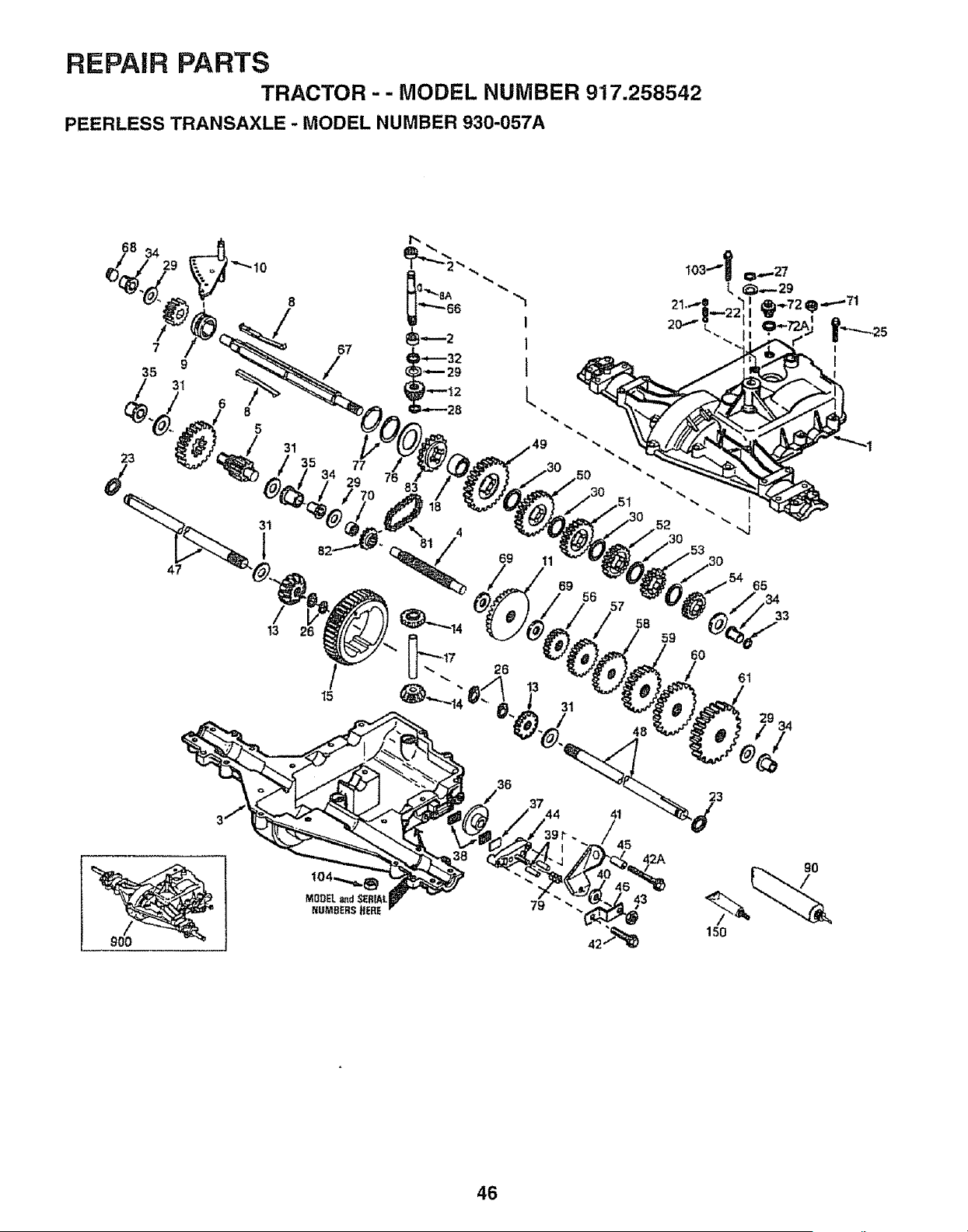
REPAIR PARTS
TRACTOR - - MODEL NUMBER 917.258542
PEERLESS TRANSAXLE - MODEL NUMBER 930-057A
68 34
23
8
/
7 67
35 9 /
_, 31
6
8
5
31
/
13
47
35 77
29
15
23
79
43
15o
46
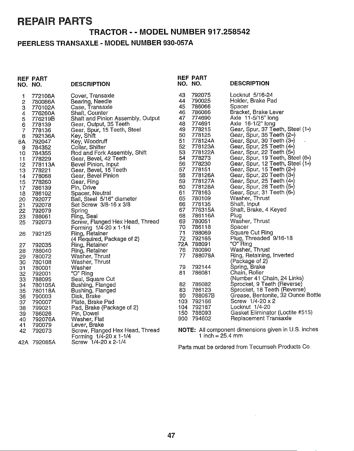
REPAIR PARTS
TRACTOR -- MODEL NUMBER 917.258542
PEERLESS TRANSAXLE - MODEL NUMBER 930-057A
REF PART REF PART
NO, NO. DESCRIPTION NO. NO. DESCRIPTION
1 772108A Cover, Transaxle 43 792075
2 780086A Bearing, Needle 44 790025
3 770102A Case, Transaxle 45 786066
4 776260A Shaft, Counter 46 786086
5 776219B Shaft and Pinion Assembly, Output 47 774690
6 778139 Gear, Output, 35 Teeth 48 774691
7 778136 Gear, Spur, 15 Teeth, Steel 49 778215
8 792136A Key, Shift 50 778125
8A 792047 Key, Woodruff 51 778124A
9 784352 Collar, Shifter 52 778123A
10 784355 Rod and Fork Assembly, Shift 53 778122A
11 778229 Gear, Bevel, 42 Teeth 54 778273
I2 778113A Bevel Pinion, Input 56 778230
13 778221 Gear, Bevel, 16 Teeth 57 778151
14 778068 Gear, Bevel Pinion 58 778126A
15 778260 Gear, Ring 59 778127A
17 786139 Pin, Drive 60 778128A
18 786102 Spacer, Neutral 61 778163
20 792077 Ball, Steel 5/16" diameter 65 780109
21 792078 Set Screw 3/8_16 x 3/8 66 776135
22 792079 Spring 67 776315A
23 788061 Ring, Seat 68 786116A
25 792073 Screw, Flanged Hex Head, Thread 69 780051
Forming 1/4-20 x 1-1/4 70 786118
26 792125 Ring, Retainer 71 788069
(4 Required, Package of 2) 72 792165
27 792035 Ring, Retainer 72A 788091
28 788040 Ring, Retainer 76 780090
29 780072 Washer, Thrust 77 788078A
30 780'I 08 Washer, Thrust
31 780001 Washer 79 792144
32 792001 "O" Ring 81 786081
33 788095 Seal, Square Cut
34 780105A Bushing, Flanged 82 786082
35 780118A Bushing, Flanged 83 786'123
36 790003 Disk, Brake 90 788067B
37 790007 Plate, Brake Pad 103 792166
38 799021 Pad, Brake (Package of 2) 104 792167
39 786026 Pin, Dowel 150 788093
40 792076A Washer, Flat 900 794602
41 790079 Lever, Brake
42 792073 Screw, Flanged Hex Head, Thread
Forming 1/4-20 x 1-1/4
42A 792085A Screw 1/4-20 x 2-t/4
Locknut 5/16-24
Holder, Brake Pad
Spacer
Bracket, Brake Lever
Axle 11-5/16" tong
Axle 16-1/2" long
Gear, Spur, 37 Teeth, Steel (1,,)
Gear, Spur, 35 Teeth (2,,)
Gear, Spur, 30 Teeth (3-)
Gear, Spur, 25 Teeth (4,)
Gear, Spur, 22 Teeth (5=)
Gear, Spur, 19 Teeth, Steel (6_)
Gear, Spur, 12 Teeth, Steel (1,,)
Gear, Spur, 15 Teeth (2.,)
Gear, Spur, 20 Teeth (3-)
Gear, Spur, 25 Teeth (4-)
Gear, Spur, 28 Teeth (5_)
(6_)Gear, Spur, 31 Teeth
Washer, Thrust
Shaft, Input
Shaft, Brake, 4 Keyed
Plug
Washer, Thrust
Spacer
Square Cut Ring
Plug, Threaded 9/16-18
."O" Ring
Washer, Thrust
Ring, Retaining, Inverted
(Package of 2)
Spring, Brake
Chain, Roller
(Number 4'1 Chain, 24 Links)
Sprocket, 9 Teeth (Reverse)
Sprocket, '18Teeth (Reverse)
Grease, Bentonite, 32 Ounce Bott}e
Screw 1/4-20 x 2
Locknut 1/4-20
Gasket Eliminator (Loctite #515)
Replacement Transaxle
NOTE: All component dimensions given in U,S,. inches
1 inch = 25°4 mm
Parts must be ordered from Tecumseh Products Co,
47
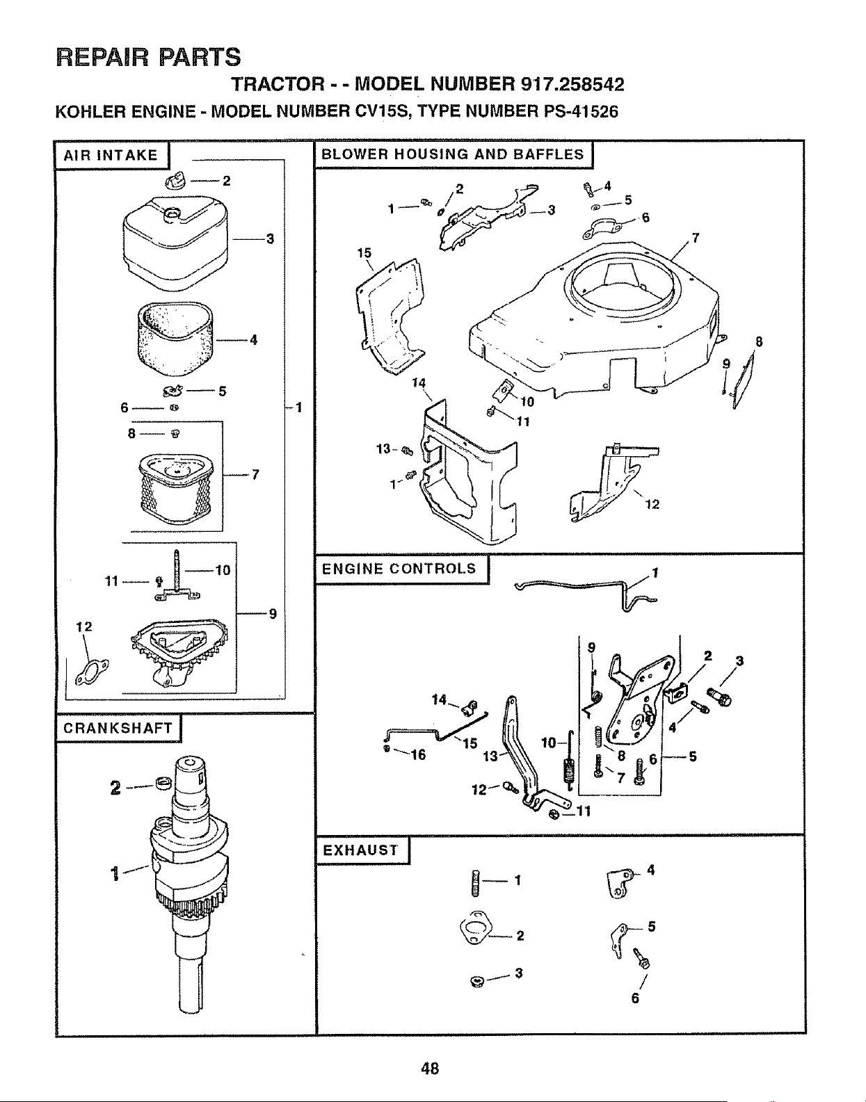
REPAIR PARTS
TRACTOR - - MODEL NUMBER 917.258542
KOHLER ENGINE - MODEL NUMBER CV15S, TYPE NUMBER PS-41526
AIR INTAKE i
_2
6_0
11--
12
_9
-1
7
==,=====,,=,===,======== =
BLOWER HOUSING AND BAFFLES !
= H H='= ,lIHI =
15
\
ENGINE CONTROLS J
_t_\ t,_o-I'
€
o
"8 6
EXHAUSTI
_1 _,--_ 4
8
48
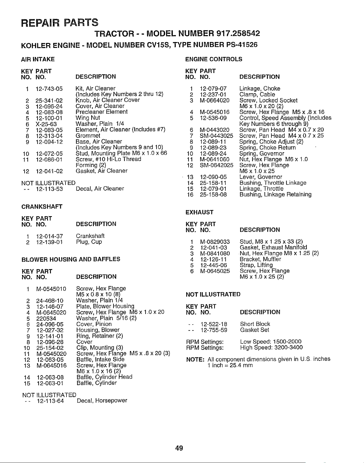
REPAIR PARTS
TRACTOR - - MODEL NUMBER 917.258542
KOHLER ENGINE - MODEL NUMBER CV15S, TYPE NUMBER PS-41526
AIR INTAKE
ENGINE CONTROLS
KEY PART KEY PART
NO. NO, DESCRIPTION NO. NO.
DESCRIPTION
2
3
4
5
6
7
8
9
12-743-05
25-34t -02
12-096-24
12-083-08
12-100-01
X-25-63
12-083_05
12-313-04
12-094-12
'10 12-072-05
tl 12-086-01
12 12-041-02
Kit, Air CIeaner 1 12-079-07
(includes Key Numbers 2 thru 12) 2 12-237-01
Knob, AirCleaner Cover 3 M-0664020
Cover, Air Cleaner
Precleaner Element 4 M-05450!6
Wing Nut 5 12-536-09
Washer, Plain 1/4
Element, Air Cleaner (Includes #7) 6 M-0443020
Grommet 7 SM-0443025
Base, Air Cleaner 8 12-089-11
(Includes Key Numbers 9 and 10) 9 12-089_23
Stud, Mounting PIate M6 x 1.0 x 66 !0 12-089-24
Screw, #10 Hi-Lo Thread 11 M-0641060
Forming (2) 12 SM-0642025
Gasket, Air Cleaner
NOT ILLUSTRATED
- _ 12-113-53 Decal, Air Cteaner
CRANKSHAFT
KEY PART
NO. NO. DESCRIPTION
1 12_014-37 Crankshaft
2 12-139-01 Plug, Cup
BLOWER HOUSING AND BAFFLES
KEY PART
NO. NO. DESCRIPTION
M-0545010
2 24-468-10
3 12-146-07
4 M-0645020
5 220534
6 24-096-05
7 12-027-32
9 12-141-01
8 12-096-28
10 25_154-02
11 M-0545020
12 12-063-05
13 M-0645016
14 12-063-08
15 12-063-01
Screw, Hex Flange
M5 x 08 x 10 (8)
Washer, Plain 1/4
Plate, Blower Housing
Screw, Hex Flange M6 x 1.0 x 20
Washer, Plain 5/16 (2)
Cover, Pinion
Housing, Blower
Ring, Retainer (2)
Cover
Clip, Mounting (3)
Screw, Hex Flange M5 x .8 x 20 (3)
Baffle, Intake Side
Screw, Hex Flange
M6 x 1_0 x 16 (2)
Baffle, Cylinder Head
Baffle, Cylinder
• 13 12-090-05
14 25-158-11
15 I2-079-01
16 25-158-08
Linkage, Choke
Clamp, Cable
Screw, Locked Socket
M6 x 1o0x 20 (2)
Screw, Hex Flange M5 x .8 x 16
Control, Speed Assembly (includes
Key Numbers 6 through 9)
Screw, Pan Head M4 x 0.7 x 20
Screw, Pan Head M4 x 0.7 x 25
Spring, Choke Adjust (2)
Spring, Choke Return
Spring, Governor
Nut, Hex Flange M6 x 1.0
Screw, Hex Flange
M6 x 1.0 x 25
Lever, Governor
Bushing, Throttle Linkage
Linkage, Throttle
Bushing, Linkage Retaining
EXHAUST
KEY PART
NO. NO,
1 M-0829033
2 12-041-03
3 M-0841080
4 12-126-11
5 12-445-06
6 M-0645025
DESCRIPTION
Stud, M8 x 1,25 x 33 (2)
Gasket, Exhaust Manifold
Nut, Hex Flange M8 x 1 25 (2)
Bracket, Muffler
Strap, Lifting
Screw, Hex Flange
M6 x 1o0x 25 (2)
NOT ILLUSTRATED
KEY PART
NO. NO.
DESCRIPTION
-- 12-522-18
-- 12-755-59
Short BJeck
Gasket Set
RPM Settings:
RPM Settings:
Low Speed: 1500-2000
High Speed: 3200-3400
NOTE: All component dimensions given in U_S inches
1 inch = 25,4 mm
NOT ILLUSTRATED
- - 12-113_64 Decal, Horsepower
49
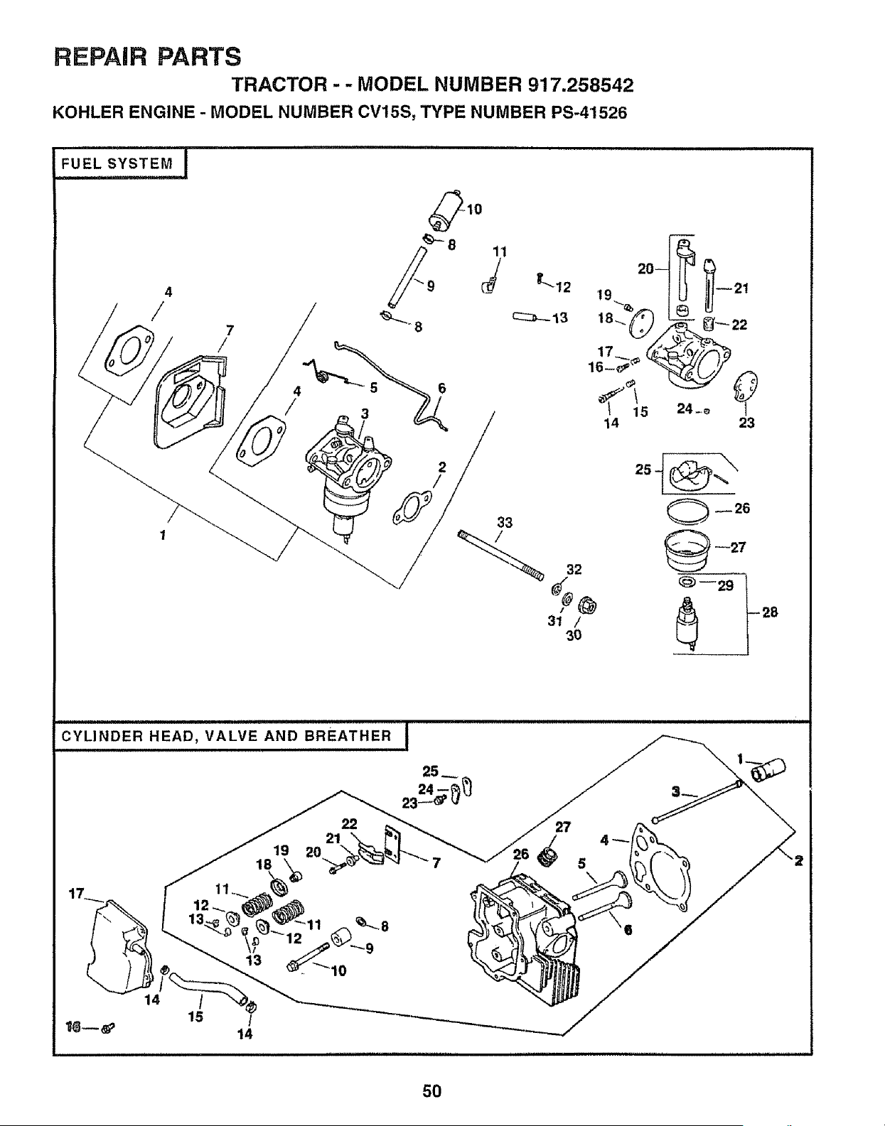
REPAIR PARTS
TRACTOR - - MODEL NUMBER 917.258542
KOHLER ENGINE- MODEL NUMBER CV15S, TYPE NUMBER PS-41526
, i
2
/
32
31 /
30
23
--27
_--29 t28
CYLINDER HEAD, VALVE AND BREATHER I
19
18
22
21
20
14
/
15
14
27
5O
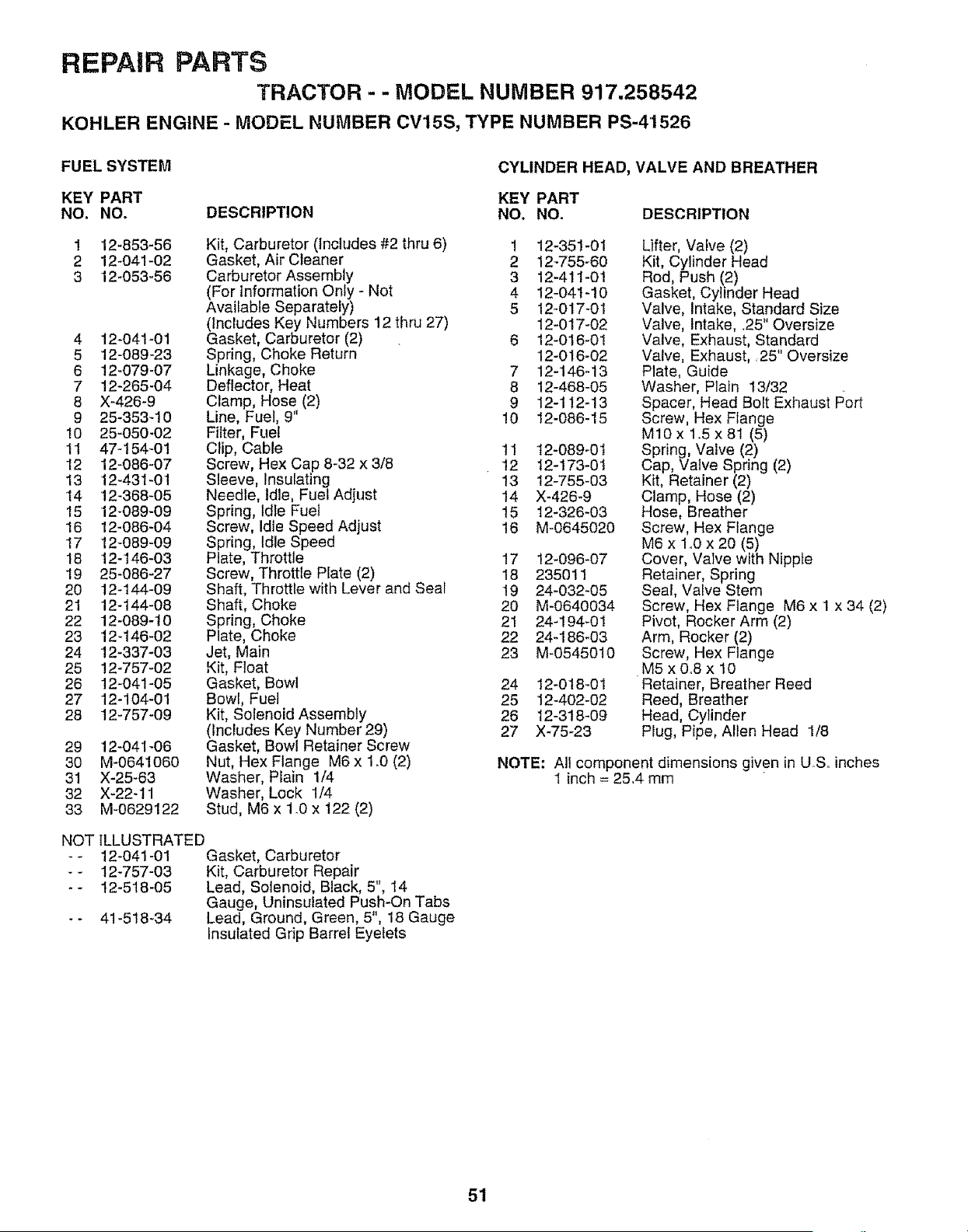
REPAIR PARTS
TRACTOR - - MODEL NUMBER 917.258542
KOHLER ENGINE - MODEL NUMBER CV15S, TYPE NUMBER PS-41526
FUEL SYSTEM
CYLINDER HEAD, VALVE AND BREATHER
KEY PART KEY PART
NO. NO. DESCRIPTION NO. NO. DESCRIPTION
12-853-56
12-04! -02
12-053-56
1
2
3
4 12-041-01
5 12-089-23
6 12-079-07
7 12-265-04
8 X-426-9
9 25-353-10
10 25-050-02
11 47-154-01
12 12-086-07
13 12-431-01
14 12-388-05
15 12-089-09
15 12-086-04
17 12-089-09
18 12-146-03
19 25-086-27
20 12-144-09
21 12-144-08
22 12-689-10
23 12-146-02
24 12-337-03
25 12-757-02
26 12-041-05
27 12-104-01
28 12_757-09
Kit, Carburetor (Includes #2 thru 6)
Gasket, Air Cleaner
Carburetor Assembly
(For Information Only - Not
Available Separately)
(Includes Key Numbers 12 thru 27)
Gasket, Carburetor (2)
Spring, Choke Return
Linkage, Choke
Deflector, Heat
Clamp, Hose (2)
Line, Fuel, 9"
Filter, Fuel
Clip, Cable 11
Screw, Hex Cap 8-32 x 3/8 12
Sleeve, Insulating 13
Needle, Idle, Fuel Adjust 14
Spring, Idle Fuel 15
Screw, Idle Speed Adjust !6
Spring, Idle Speed
Plate, Throttle 17
Screw, Throttle Plate (2) 18
Shaft, Throttle with Lever and Seal 19
Shaft, Choke 20
Spring, Choke 21
Plate, Choke 22
Jet, Main 23
Kit, Float
Gasket, Bowl 24
Bowl, Fuel 25
Kit, Solenoid Assembly 28
(Includes Key Number 29) 27
Gasket, Bowl Retainer Screw
Nut, Hex Flange M6 x 1o0(2)
Washer, Plain 1/4
Washer, Lock 1/4
Stud, M6 x 1.0 x 122 (2)
29 12-041-06
3O M-0641060
31 X-25-63
32 X-22-11
33 M-0629122
NOT ILLUSTRATED
-- 12-041-01 Gasket, Carburetor
-- 12-757-03 Kit, Carburetor Repair
- - 12-518-05 Lead, Solenoid, Black, 5", 14
Gauge, Uninsulated Push-On Tabs
- - 41-518-34 Lead, Ground, Green, 5", 18 Gauge
Insulated Grip Barrel Eyelets
! 12-351-01
2 12-755-60
3 12-411-0!
4 12-041-10
5 12-017-01
12-017-02
6 12-016-01
12-016-02
7 12-146-13
8 12-468-05
9 12-112-13
10 12-086-15
12-089-01
12-173-0t
12-755_03
X-426_9
12_326-03
M-0645020
12-096-07
235011
24-032-05
M-0640034
24_194-01
24_186-03
M-0545010
12-0t8-01
12-402-02
12-318409
X-75-23
Lifter, Valve (2)
Kit, Cylinder Head
Rod, Push (2)
Gasket, Cylinder Head
Valve, Intake, Standard Size
Valve, Intake, _25" Oversize
Valve, Exhaust, Standard
Valve, Exhaust, 25" Oversize
Plate, Guide
Washer, Plain 13/32
Spacer, Head Bolt Exhaust Port
Screw, Hex Flange
M10x 1.5 x 8I (5)
Spring, Valve (2)
Cap, Valve Spring (2)
Kit, Retainer (2)
Clamp, Hose (2)
Hose, Breather
Screw, Hex Flange
M6 x 1.0 x 20 (5)
Cover, Valve with Nipple
Retainer, Spring
Seal, Valve Stem
Screw, Hex Flange M6 x 1 x 34 (2)
Pivot, Rocker Arm (2)
Arm, Rocker (2)
Screw, Hex Flange
M5 x 0,,8 x 10
Retainer, Breather Reed
Reed, Breather
Head, Cylinder
Plug, Pipe, Allen Head 1/8
NOTE: All component dimensions given in US. inches
1 inch = 25.4 mm
51
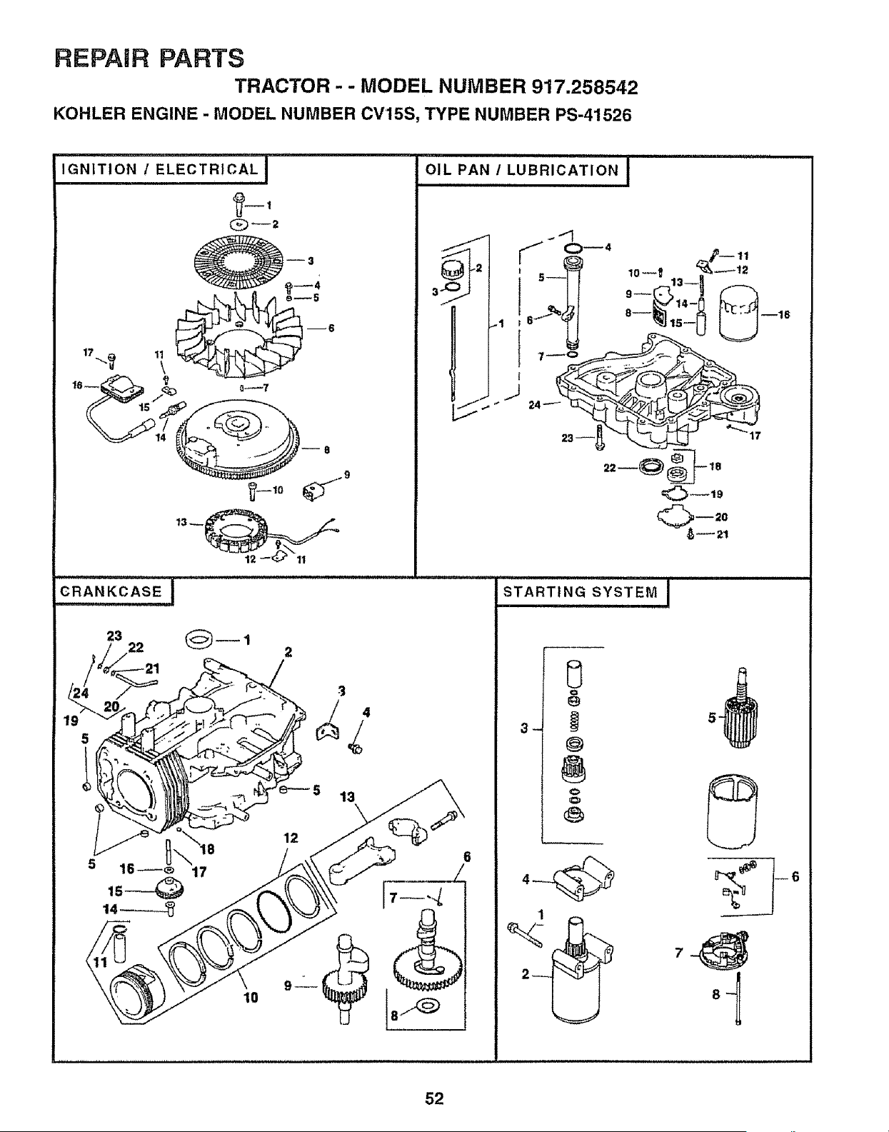
REPAIR PARTS
TRACTOR - - MODEL NUMBER 917.258542
KOHLER ENGINE - MODEL NUMBER CV15S, TYPE NUMBER PS-41526
IGNITION/ ELECTRICAL,,I
Q--2
23 1
5 13
11111111111111111
OIL PAN / LUBRICATION J
iiiiiiiii,i1_ilU,,,,lU,Uu u i i u
STARTING SYSTEM !
0
@
@
.
52
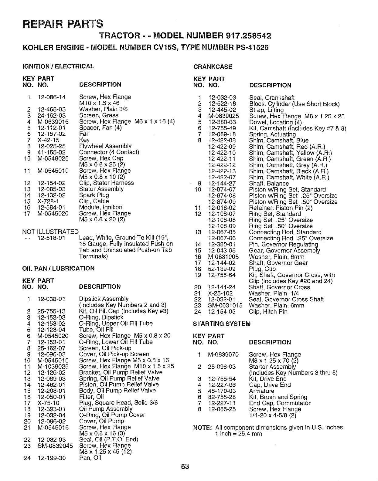
REPAIR PARTS
TRACTOR - - MODEL NUMBER 917.258542
KOHLER ENGINE - MODEL NUMBER CV15S, TYPE NUMBER PS-41526
IGNITION / ELECTRICAL
CRANKCASE
KEY PART KEY PART
NO. NO. DESCRIPTION NO. NO. DESCRIPTION
1 12-086-14 Screw, Hex Flange 1 12-032-03
M10x 1_5x46 2 12-522-18
2 12-468-03 Washer, Plain 3/8 3 127445-02
3 24-162-03 Screen, Grass 4 M-0839025
4 M-0639016 Screw, Hex Flange M6 x 1 x 16 (4) 5 t2-380-03
5 12-112-01 Spacer, Fan (4) 6 12-755-49
6 12-157-02 Fan 7 12-089-18
7 X-42-15 Key 8 12_422-08
8 12-025-25 Flywheel Assembly 12-422-09
9 41-155-02 Connector (4 Contact) 12-422-10
10 M-0548025 Screw, Hex Cap 12-422-11
M5 x 0_8 x 25 (2) 12-422-12
11 M-0545010 Screw, Hex Flange 12-422_13
M5 x 0.8 x 10 (2) 12-422-07
12 12_154-02 Clip, Stator Harness 9 12-I44-27
13 12-085-03 Stator Assembly 10 12-874-07
14 12-132-02 Spark Plug 12-874-08
15 X-728-1 Clip, Cable 12-874-09
16 12-584-01 Module, Ignition 11 12-018-02
17 M-0545020 Screw, Hex Flange 12 12-108_07
M5 x 0.8 x 20 (2) 12-108-08
12-t 08-09
NOT ILLUSTRATED 13 12-067-05
- - 12-518-01 Lead, White, Ground To Kill (I9", 12-067-06
18 Gauge, Fully Insulated Push-on 14 12-380-01
Tab and Uninsulated Push-on Tab 15 12-043-05
Terminals) 16 M-0631005
17 12-144-02
OIL PAN 1 LUBRICATION 18 52-139-09
19 12_755_64
DESCRIPTION
KEY PART
NO. NO.
t2-038-01
2 25-755-t3
3 12-153-03
4 12-t53-02
5 12-t23-04
6 M-0545020
7 12-t53-01
8 25-162-07
9 12-096-03
10 M-0545016
11 M-1039025
12 12-126-02
13 12-089-03
14 12-462-0I
15 12-208-01
16 t2-050-01
17 X-75-10
18 12-393-01
19 12-032-04
20 12-096-02
21 M-0545016
22 12-032-03
23 SM-0839045
Dipstick Assembly
(Includes Key Numbers 2 and 3)
Kit, Oii Fill Cap (Includes Key #3)
O-Ring, Dipstick
O-Ring, Upper Oil Fill Tube
Tube, Oil Fill
Screw, Hex Flange M5 x 0.8 x 20
O-Ring, Lower Oil Fill Tube
Screen, Oil Pick-up
Cover, Oil Pick-up Screen
Screw, Hex Flange M5 x 0.8 x 16
Screw, Hex Flange M10 x 1.5 x 25
Bracket, Oil Pump Relief Valve
Spring, Oil Pump Relief Valve
Piston, Oil Pump Relief Valve
Body, Oit Pump Relief Valve
Fi}ter, Oil
Plug, Square Head, Solid 3/8
Oil Pump Assembly
O-Ring, Oil Pump Cover
Cover, Oil Pump
Screw, Hex Flange
M5 x 0.8 x 16 (3)
Seal, Oil (PoT.Co End)
Screw, Hex Flange
M8 x 1_25 x 45 (12)
Pan, Oil
53
24 12-199-30
20 124144-24
21 X-25-102
22 12-032-01
23 SM-0631015
24 12-154-05
Seal, Crankshaft
Block, Cylinder (Use Short Block)
Strap, Lifting
Screw, Hex Flange M8 x 1.25 x 25
Dowel, Locating (4)
Kit, Camshaft (includes Key #7 & 8)
Spring, Actuating
Shim, Camshaft, Blue
Shim, Camshaft, Red (A.R)
Shim, Camshaft, Yellow (A.R:)
Shim, Camshaft, Green (A.R)
Shim, Camshaft, Grey (AR.)
Shim, Camshaft, Black (AR)
Shim, Camshaft, White (A.R.)
Shaft, Balance
Piston w/Ring Set, Standard
Piston w/Ring Set _25" Oversize
Piston w/Ring Set .50" Oversize
Retainer, Piston Pin (2)
Ring Set, Standard
Ring Set .25" Oversize
Ring Set ..50" Oversize
Connecting Rod, Standard
Connecting Rod .25" Oversize
Pin, Governor Regulating
Gear, Governor Assembly
Washer, Plain, 6mm
Shaft, Governor Gear
Plug, Cup
Kit, Shaft, Governor Cross, with
Clip (Includes Key #20 and 24)
Shaft, Governor Cross
Washer, Plain 1/4
Seal, Governor Cross Shaft
Washer, Plain, 6mm
Clip, Hitch Pin
STARTING SYSTEM
KEY PART
NO. NOr DESCRIPTION
3
4
5
6
7
8
M-0839070
25-098-03
12-755-54
12-227-06
45-170-03
82-755-28
12-227-11
12-086-25
Screw, Hex Flange
M8 x 1_25 x 70 (2)
Starter Assembty
(includes Key Numbers 3 thru 8)
Kit, Drive End
Cap, Drive End
Armature
Kit, Brush and Spring
End Cap, Commutator
Screw, Hex Flange
!/4-20 x 4-5/8 (2)
NOTE: AII component dimensions given in U.S. inches
1 inch = 254 mm

54

SUGGESTED GUIDE FOR SIGHTING SLOPES FOR SAFE OPERATION
7"
SIGHTING "" ---..
...CUT OU"
ONLY RIDE UP AND DOWN HILL,
NOT ACROSS HILL
SIGHT AND HOLD THIS LEVEL WITH
SKY LINE OR TREE.
f
15 ° MAX.
= === =,H == == == H = = IIIIHI"N=""H"====H="==HI===
itA Opora'oyourT c'orupanO0ownthe'aceo'sopes notI
F greater than 15 ), never across the face. Make turns gradu-
ally to prevent tipping or loss of control. Exercise extreme i
caution when changing direction on slopes. I

OWNER'S
MANUAL
MODEL NO.
917.258542
IF YOU NEED
REPAIR SERVICE
OR PARTS:
FOR REPAIR SERVICE, CALL
THIS TOLL FREE NUMBER:
1-800-4-REPAIR
(1-800-473-7247)
FOR REPLACEMENT PARTS
iNFORMATION AND
ORDERING, CALL THIS
TOLL FREE NUMBER:
1-800-FON-PART
(1-800-366-7278)
FOR CONSUMER ASSISTANCE
HOT LINE, CALL THIS
TOLL FREE NUMBER:
1-800-659-5917
®
15.0 HP
ELECTRIC START
42" MOWER
6 SPEED TRANSAXLE
LAWN TRACTOR
Each tractor has its own model number Each engine has
its own model number
The model number for your tractor will be found on the
model plate located under the seat
The model number for your engine will be found on the
blower housing of the engine.
All parts listed herein may be ordered from any Sears,
Roebuck and COoService Center/Department and most Re-
tail Stores.
WHEN ORDERING REPAIR PARTS, ALWAYS GIVE THE
FOLLOWING INFORMATION:
- PRODUCT - TRACTOR
• MODEL NUMBER - 917.258542
o ENGINE MODEL NO. - CV15S TYPE NO. PS=41526
o PART NUMBER
,' PART DESCRIPTION
Your Sears merchandise has added value when you
consider Sears has service units nationwide staffed with
Sears trained technicians,,., professional technicians
specifically trained to insure that we meet our pledge to
you, we service what we sell.
160474 3424.97 TR
Printed in U.S A


