ENGLISH ESPAÑOL
Owner's Manual
Manual del Propietario
THROUGH-THE-WALL AIR CONDITIONER
ACONDICIONADO DE AIRE A TRAVES DE PARED
Model, Modelo 580.75119
Distributed by Sears, Roebuck and Co., Hoffman Estates, IL 60179
www.sears.com
®
ENERGY STAR

-2-
TABLE OF CONTENTS
WARRANTY
-2-
FULL ONE YEAR WARRANTY ON
THROUGH-THE-WALL AIR CONDITIONER
For one year from the date of purchase, when this
air conditioner is operated and maintained for
normal room cooling according to the instructions in
this owner's manual, Sears will repair this air
conditioner, free of charge, if defective in material or
workmanship.
WARRANTY SERVICE IS AVAILABLE BY
CONTACTING SEARS SERVICE AT 1-800-4-
MY-HOME
®
.
This warranty applies only while this product is in
use in the United States.
This warranty gives you specific legal rights, and
you may also have other rights which vary from
statetostate.
Distributed by Sears, Roebuck and
Co., Hoffman Estates, IL 60179
TABLE OF CONTENTS
........................
2
WARRANTY
..............................................
2
SAFETY
.....................................................
3
Important Safety Instructions
......................
3
ELECTRICAL REQUIREMENTS
.......
4
INSTALLATION
........................................
5
Installation Requirements
.........................
5
Installation
................................................
6
Procedure A .............................................7
Procedure B .............................................8
Procedure C...........................................10
OPERATION
...........................................
12
How and Why
.........................................
12
Normal Sounds
......................................
12
Capacity and Running Time
...................
12
Features
.................................................
13
Using the Air Conditioner
.......................
13
Air Conditioner Features
........................
14
MAINTENANCE
.....................................
16
Air Filter Cleaning
...................................
16
Air Conditioner Cleaning
........................
16
How to Remove the Front Grille
.............
16
How to Replace the Front Grille.............16
TROUBLESHOOTING
.........................
17
Before Calling for Service
......................
17
ESPAÑOL
................................................
18
MASTER PROTECTION
AGREEMENTS
......................................35
SERVICE NUMBERS
............
Back Cover
-3-
ENGLISH
SAFETY
IMPORTANT SAFETY INSTRUCTIONS
The safety instructions below will tell you how to use your room air conditioner to avoid harm to yourself or
damage to your ROOM AIR CONDITIONER.
FOR YOUR SAFETY
Do not store or use gasoline or other flammable
vapors and liquids in the vicinity of this or any other
appliance. Read product labels for flammability and
other warnings.
PREVENT ACCIDENTS
To reduce the risk of fire, electrical shock, or injury
to persons when using your air conditioner, follow
basic precautions, including the following:
• Be sure the electrical service is adequate for the
model you have chosen.
• If the air conditioner is to be installed in a window,
you will probably want to clean both sides of the
glass first. If the window is a triple-track type with a
screen panel included, you may want to remove
the screen completely before installation.
• Be sure the air conditioner has been securely and
correctly installed according to the instructions in
this manual.
Save this manual and installation instructions for
possible future use in removing or reinstalling this
unit.
• Use gloves when handling the air conditioner.
Be careful to avoid cuts from sharp metal fins on
front and rear coils.
ELECTRICAL INFORMATION
The complete electrical rating of your new room air
conditioner is stated on the serial plate. Refer to the
rating when checking the electrical requirements.
• Be sure the air conditioner is properly grounded.
To minimize shock and fire hazards, proper
grounding is important. The power cord is
equipped with a three-prong grounding plug for
protection against shock hazards.
• Your air conditioner must be plugged into a
properly grounded wall receptacle. If the wall
receptacle you intend to use is not adequately
grounded or protected by a time delay fuse or
circuit breaker, have a qualified electrician install
the proper receptacle.
• Do not run air conditioner with packing sheet of
the back of the sleeve, and packing corner and
blue tape of the air conditioner. This could result in
mechanical damage within the air conditioner.
• Do not use an extension cord or an adapter
plug.
ENERGY SAVING IDEAS
• The capacity of the room air conditioner must fit
the room size for efficient and satisfactory
operation.
• Install the room air conditioner on the shady side
of your home. A window that faces north is best
because it is shaded most of the day.
• Do not block air conditioner flow inside with blinds,
curtains, or furniture; or outside with shrubs,
enclosures, or other buildings.
• Close the floor and wall registers and the fireplace
damper so cool air does not escape up the
chimney or into the duct work.
• Keep blinds and drapes in other windows closed
during the sunniest part of the day.
• Clean the air filter as recommended in the
MAINTENANCE section of this manual.
• Proper insulation and weather stripping in your
home will help keep warm air out and cool air in.
• External house shading with trees, plants or
awnings will help reduce the air conditioner's work
load.
• Operate heat producing appliances such as
ranges, washers, dryers, and dishwashers during
the coolest part of the day.
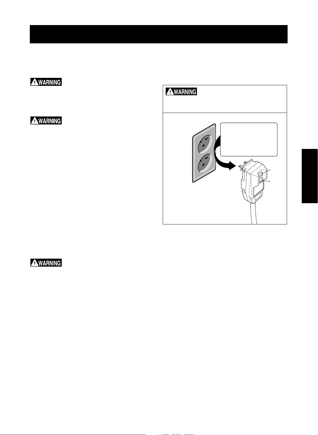
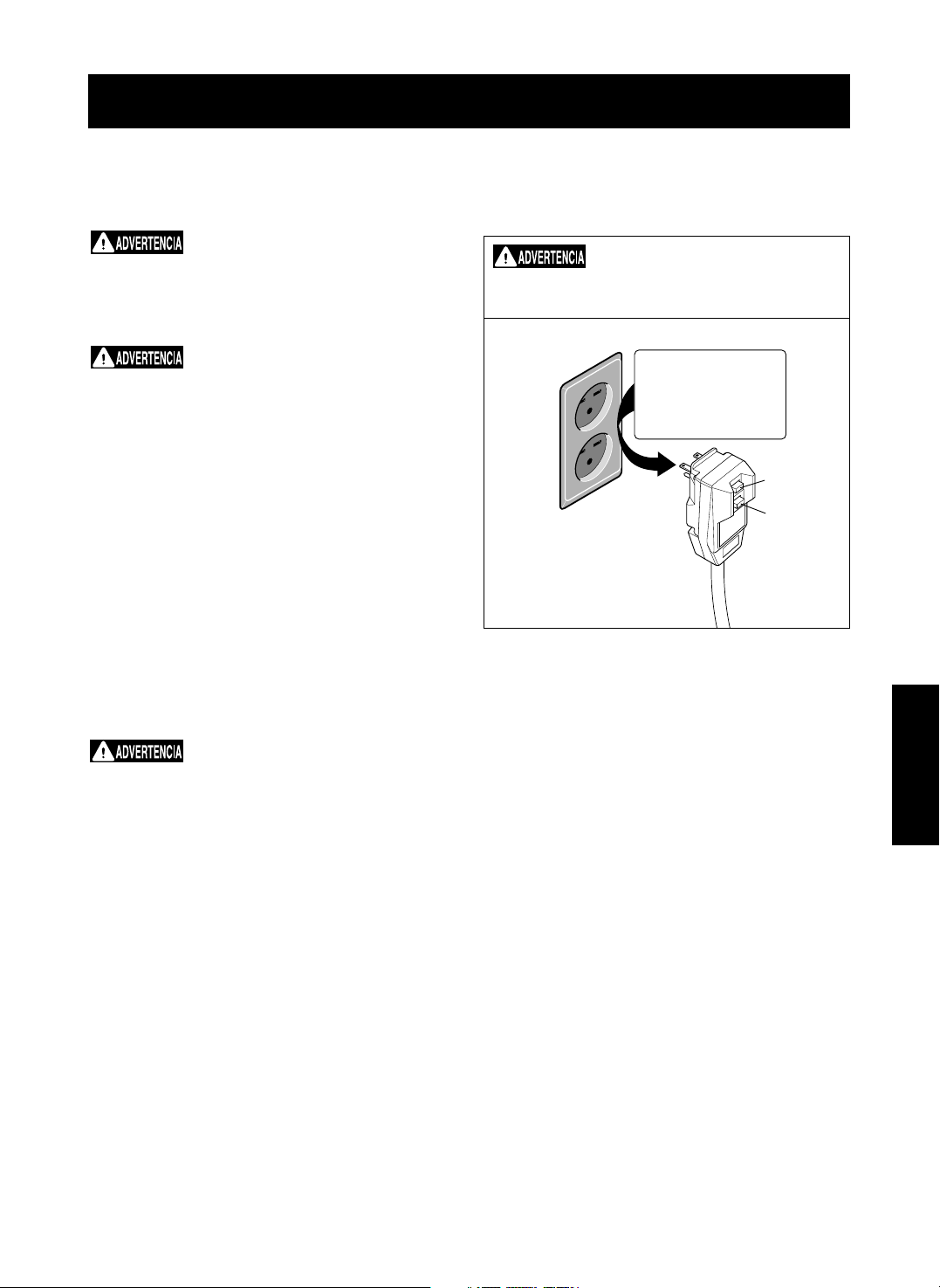
Grounding type
wall receptacle
Do not under any
circumstances cut,
remove, or bypass
the grounding prong
from this plug.
Power supply cord
with 3-prong
grounding plug
Reset
Test
Avoidfirehazardorelectricshock.
Do not use an extension cord or an adapter plug.
Do not remove any prong from the power cord.
-4-
ELECTRICAL REQUIREMENTS
OBSERVE ALL LOCAL CODES AND
ORDINANCES.
DO NOT, UNDER ANY CIRCUMSTANCES,
REMOVE THE POWER SUPPLY CORD
GROUND PRONG.
ELECTRICAL GROUND IS REQUIRED ON
THIS APPLIANCE.
208/230-volt 60 Hz and 115-volt 60 Hz, AC
only, 15A fused and properly grounded
electrical supply is required. A time delay fuse
or time delay circuit breaker is recommended.
Use a dedicated circuit, serving only this
appliance.
DO NOT USE AN EXTENSION CORD.
RECOMMENDED GROUNDING METHOD
For your personal safety, this appliance must
be grounded. This appliance has a power
supply cord with a 3-prong grounding plug. To
minimize possible shock hazard, the cord must
be plugged into a mating grounding type wall
receptacle and grounded in accordance with
the National Electrical Code (ANSI/NFPA 70)
latest edition and all local codes and
ordinances. If a mating wall receptacle is not
available, it is the personal responsibility and
obligation of the customer to have a properly
grounded 3-prong wall receptacle installed by a
qualified electrician.
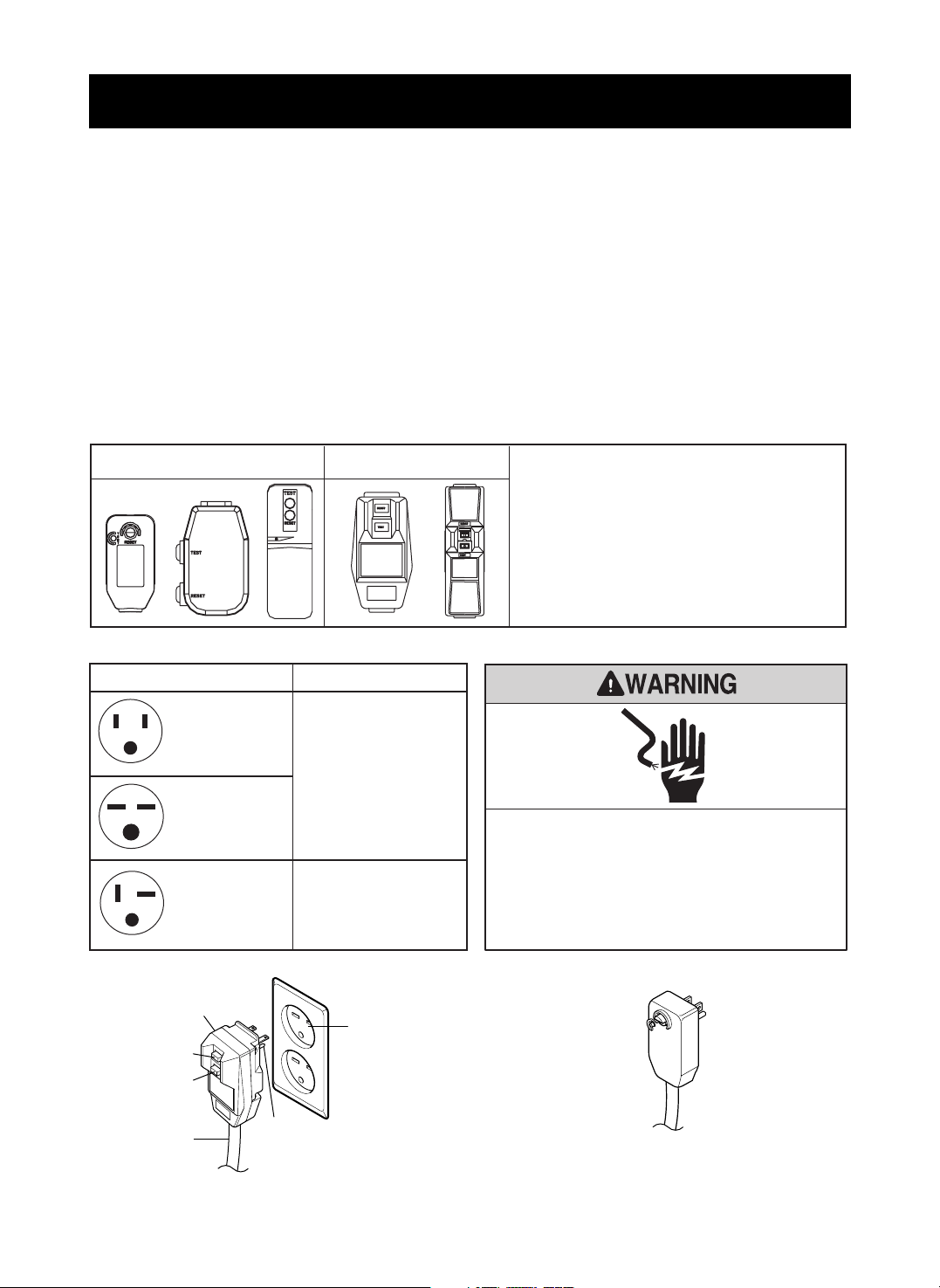
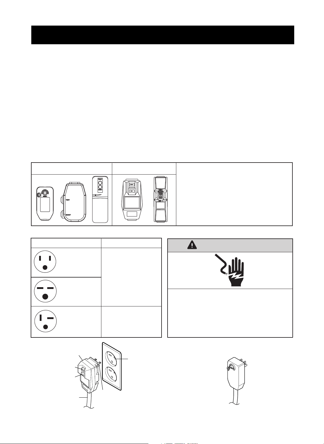
115V~ 230V~
Power cord may include a current interrupter
device. A test and reset button is provided on the
plug case. The device should be tested on a
periodic basis by first pressing the TEST button
and then the RESET button. If the TEST button
does not trip or if the RESET button will not stay
engaged, discontinue use of the air conditioner and
contact a qualified service technician.
Electrical Shock Hazard
Plug into a grounded 3 prong outlet.
Do not remove ground prong.
Do not use an adapter.
Do not use an extension cord.
Failure to follow these instructions can result in
death, fire, or electrical shock.
Use Wall Receptacle Power Supply
Standard 125V,
3-wire grounding
receptacle rated
15A, 125V AC
Standard 250V,
3-wire grounding
receptacle rated
15A, 250V AC
Use 15 AMP. time
delay fuse or 15 AMP.
circuit breaker.
Use 20 AMP. time
delay fuse or 20 AMP.
circuit breaker.
Standard 250V,
3-wire grounding
receptacle rated
20A, 250V AC
NOTE:
The shape may be different according to its model.
3-prong
grounding
plug
Reset
Test
Ground
prong
Power
supply
cord
3-prong
grounding
type wall
receptacle
(208/230-volt 60 Hz)
(115-volt 60 Hz)

-5-
ENGLISH
INSTALLATION
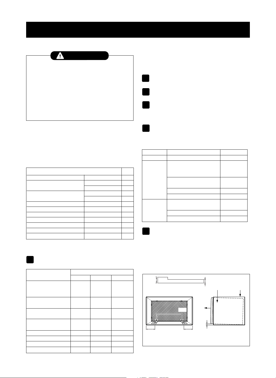
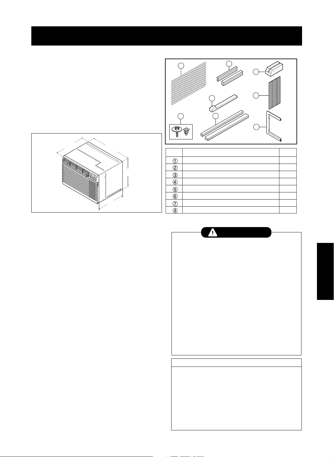
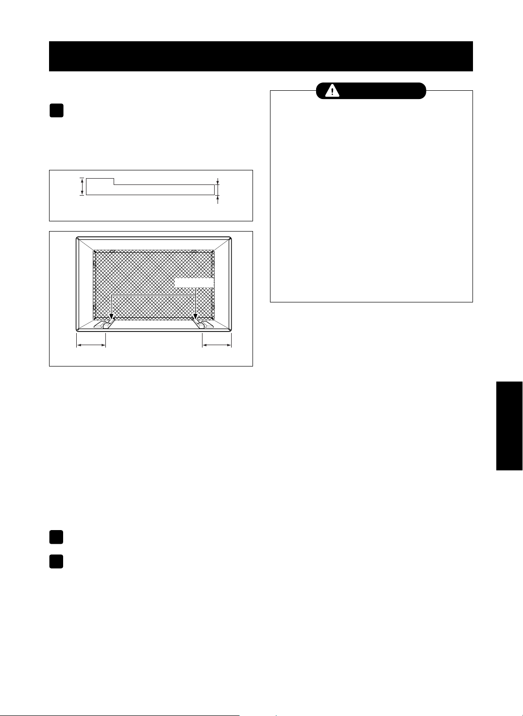
INSTALLATION REQUIREMENTS
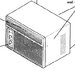
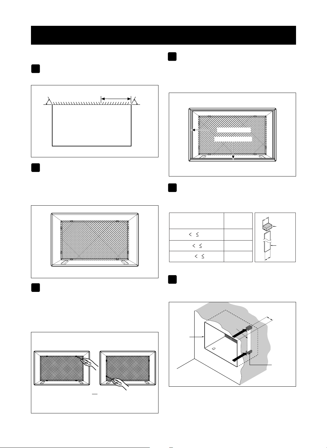
If you use an existing wall sleeve, you should
measure its dimensions.
Install the new air conditioner according to these
installation instructions to achieve the best
performance. All wall sleeves used to mount the
new air conditioner must be in good structural
condition and have a rear grille to securely attach
the new air conditioner. (FIG. 1)
With the Kenmore folding sleeve,youcan
maintain the best performance of the new air
conditioner.
ELECTRICAL SERVICE
Check your available electrical service. The power
supply available must be the same as that shown
on the unit nameplate (found on left side of cabinet).
All models are equipped with a 3-prong service plug
to provide proper service and safe positive
grounding. Do not change plug in any way. Do not
use an adapter plug. If your present wall outlet does
not match your plug, call a qualified electrician to
make the necessary corrections. SAVE CARTON
for storage and this OWNER'S MANUAL for future
reference. The carton is the best way to store unit
during winter or when not in use.
INSTALLATION HARDWARE
14-
13
/
32
"
(366 mm)
24-
21
/
32
"
(626 mm)
18"(458 mm)
19-
21
/
32
"
(499 mm)
1
4
5
6
7
3
2
8
2 Size options
2 Size options
To avoid risk of personal injury, property damage,
or product damage due to the weight of this
device and sharp edges that may be exposed:
• Air conditioners covered in this manual pose an
excessive weight hazard. Two or more people
are needed to move and install the unit.
To prevent injury or strain, use proper lifting and
carrying techniques when moving unit.
•
Carefully inspect location where air conditioner
will be installed. Be sure it will support the weight
of the unit over an extended period of time.
• Handle air conditioner with care. Wear
protective gloves whenever lifting or carrying the
unit. AVOID the sharp metal fins of front and
rear coils.
• Make sure air conditioner does not fall during
installation.
CAUTION
REQUIRED TOOLS:
• Tight Fitting gloves
• Standard screwdriver
• Phillips screwdriver
• Pliers
• Sharp knife
• 3/8-inch open end
wrench or adjustable
wrench
• 1/4-inch hex socket
and ratchet
• Tape measure
• Electric drill
• 1/4-inch drill bit
FIG. 1
Air Conditioner
ITEM NAME OF PARTS Q'TY
1 PLASTIC GRILLE 1
2 HORIZONTAL INSULATION STRIPS 2
3 AROUND INSULATION STRIPS 2
4 SUPPORT BLOCK 2
5BAFFLE 1
6 TRIM FRAME 2
7SHIM 2
8
PLASTIC NUTS AND WASHER SCREWS
4
INSTALLATION
•
Pick a location which will allow the conditioned air to
blow into the area you want. Good installation with
special attention to the proper position of the unit will
lessen the chance that service will be needed.
ITEMS IN INSTALLATION HARDWARE
You may not need all parts in the kit. Discard unused
parts
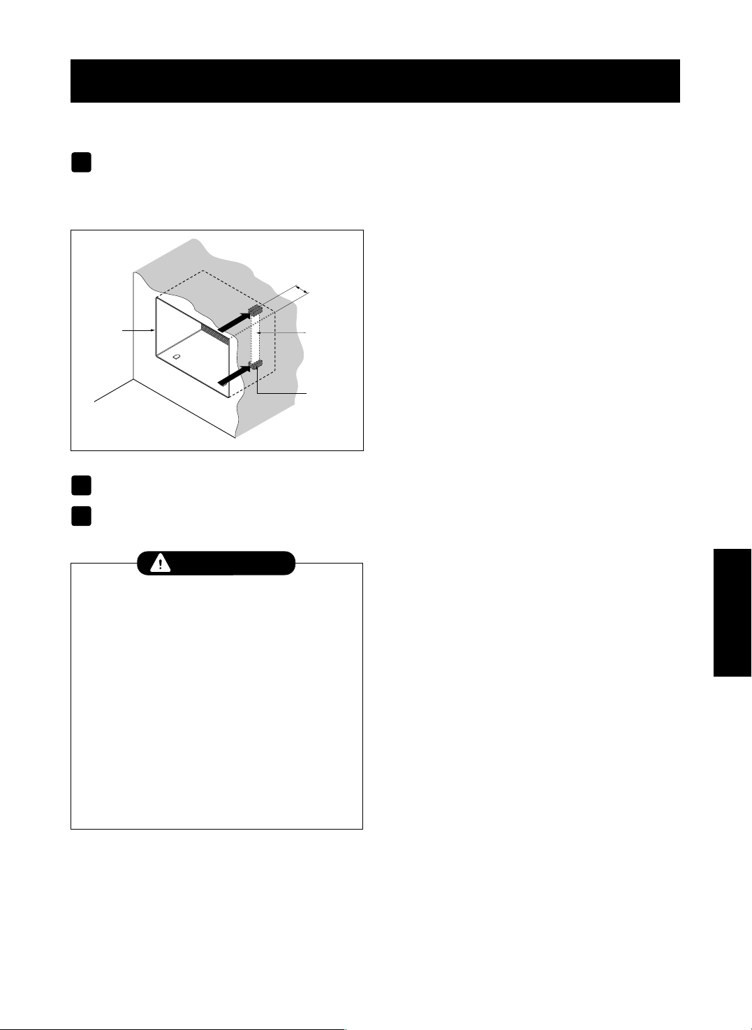
HOW TO INSTALL
Identify the existing wall sleeve before installing
the unit from the listed below.
NOTE: All wall sleeves used to mount the new Air
Conditioner must be in sound structural condition
and have a rear grille that securely attaches to
sleeve, or rear flange that serves as a stop for the
Air Conditioner,
Remove old air conditioner from existing wall
sleeve.
Clean the interior of an existing sleeve.
(Do not disturb seals.)
Wall sleeve must be securely fastened in wall
before installing the air conditioner. Use the
nails or screws through sleeve into wall, if
needed. Repaint sleeve if needed.
Prepare the wall sleeve for installation of the
unit. If you plan to use your existing wall sleeve,
and it is not Kenmore, use procedure B or C
below.
Install new unit into wall sleeve.
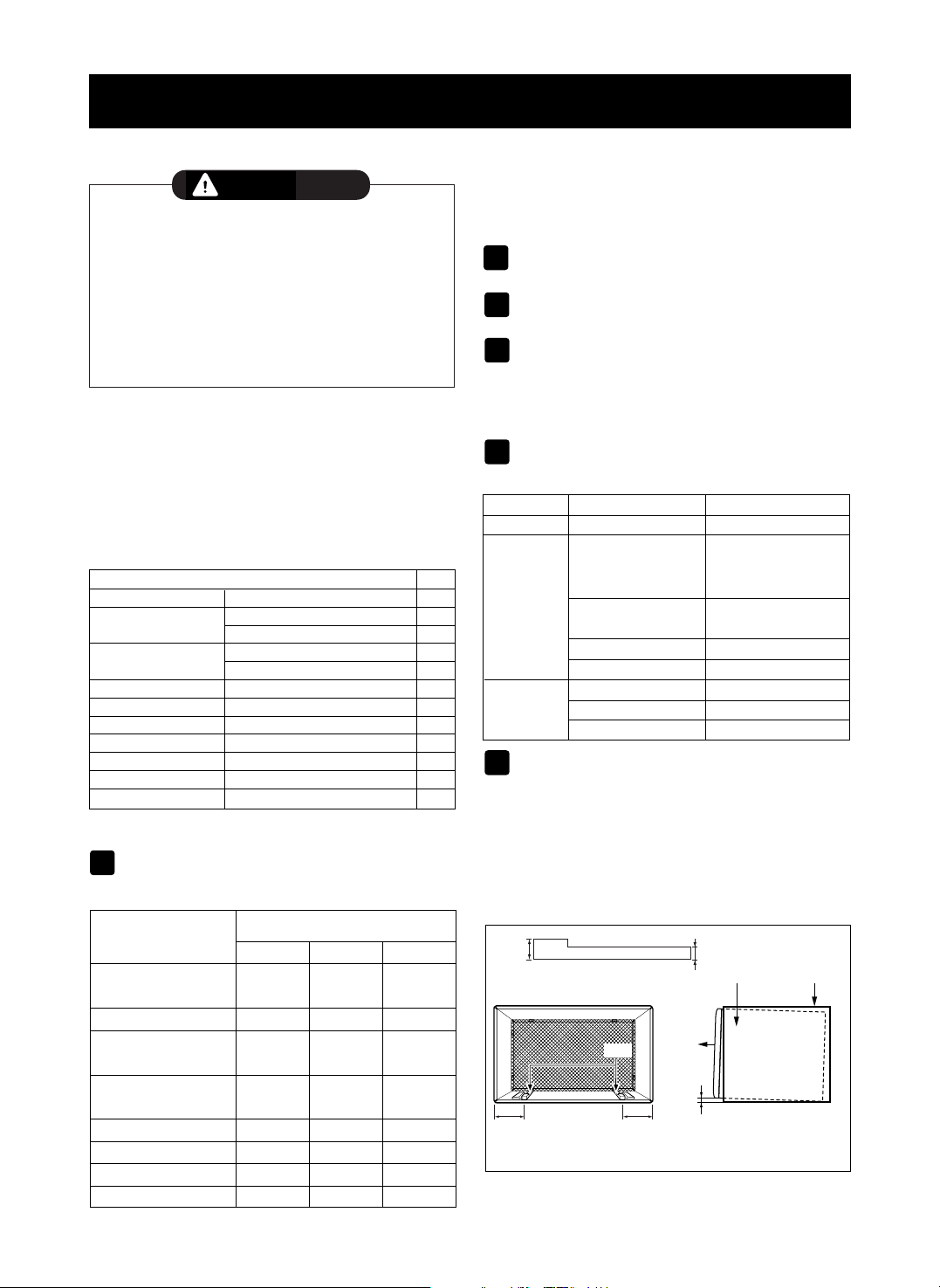
CAUTION: When installation is completed,
replacement unit MUST have a rearward slope as
shown. To achieve 1/4" slope, remove the backing
from the 13" shim strips and attach them as shown
below in Fig. 2. Place the higher portion of shim to
the front of the rib on base of wall sleeve.
-6-
INSTALLATION
1
2
3
4
5
6
We strongly recommend the removal of the
old wall sleeve and the installation of a new
Kenmore folding Wall Sleeve.
If you decide to keep the existing wall sleeve,
you have to redirect the louvers at the back of the
wall sleeve illustration. The use of pliers is
recommended. If you DO NOT redirect, you run
the risk of poor performance or product failure.
This is not covered under the terms of the
Kenmore warranty.
CAUTION
ITEM (inches) Qty.
Plastic grille 26
3
/
4
x16
1
/
2
1
Horizontal Insulation Strips
1
3
/
8
x
5
/
8
x27
3
/
16
1
1
3
/
8
x1
3
/
8
x27
3
/
16
1
Around Insulation Strips
1
3
/
8
x
3
/
4
x61
1
/
2
1
1
3
/
8
x1
3
/
8
x61
1
/
2
1
Support Block 1
3
/
4
x1
3
/
8
x4
5
/
16
2
Baffle
14 x
4
1
/
2
x
1
/
8
1
Shim 13 x 1 x
3
/
4
2
Trim Frame 2
Washer Screw 4
Nuts(Plastic) 4
Grille Rear 1
Wall Sleeve Dimensions (inches)
Brand
Width Height Depth
White-Westinghouse
25-1/2 15-1/4
16, 17-1/2
Frigidaire
or 22
Carrier (52F series)
General Electric
26 15-5/8 16-7/8
/Hotpoint
Whirlpool 25-7/8 16-1/2
17-1/8
or 23
Fedders/Emerson 27 16-3/4
16-3/4
or 19-3/4
Sears/Kenmore 25-7/8 15-17/32 16-23/32
Emerson/Fedders 26-3/4 15-3/4 15
Carrier (51S Series) 25-3/4 16-7/8 18-5/8
Friedrich 27 16-3/4 16-3/4
Procedure Brand
Depth(inches)
A Sears/Kenmore 16-23/32
White-Westinghouse
Frigidaire Carrier
16, 17-1/2
(52F series)
or 22
B
General Electric
16-7/8
/Hotpoint
Whirlpool 17-1/8 or 23
Carrier (51S series)
18-5/8
Fedders/Emerson
16-3/4
or 19-3/4
C
Emerson/Fedders 15
Friedrich 16-3/4
1/4"
Wall Sleeve
FRONT
UNIT
SHIM PLACEMENT UNIT INSTALLATION
1" high
3
/
4
" High
Shim
6" 6"
FIG. 2
-7-
ENGLISH
INSTALLATION
PROCEDURE A
If you are using the new sleeve (optionally
supplied with your unit),skip to step 3.
Otherwise, install the plastic grille from the kit.
Cut the plastic grille to 25-1/2" wide and 15-1/4"
high. Place the plastic grille to the inside of the
wall sleeve at the rear flange.
Fasten the 4 washer screws to secure the grille
to the wall sleeve. If you need plastic nuts to
mount plastic grille to the inside of the wall
sleeve, there are plastic nuts in the installation
kit. The nuts are installed from the inside of the
sleeve and are pressed into the square holes of
the rear flanges.
Remove the backing from the Horizontal
Insulation strip 1
3
/
8
x
3
/
8
x27
3
/
16
and attach that
to the inside bottom of the sleeve as shown
below. Remove the backing from the Around
Insulation strip 1
3
/
8
x
3
/
4
x61
1
/
2
and attach that
to the inside front of the sleeve as shown
below.
To assemble trim, snap the tab of each piece
into the slot of the other piece as shown below.
Slide trim over the front of the air conditioner
until trim is flush with sleeve as shown below.
FIG. 3
Around Insulation
Horizontal Insulation
FIG. 5
or
FIG. 4
1
2
3
4
Wall
Trim (2 ea)
FIG. 6
• Air conditioners covered in this manual pose
an excessive weight hazard. Two or more
people are needed to move and install the unit.
To prevent injury or strain, use proper lifting
and carrying techniques when moving unit.
• When handling the air conditioner, be careful
to avoid cuts from sharp metal fins on front and
rear coils.
• Make sure air conditioner does not fall during
removal.
• If unit does not operate after installation check, to be
sure the circuit interrupter has not been tripped. Refer
to the Troubleshooting guide for reset procedure.
CAUTION
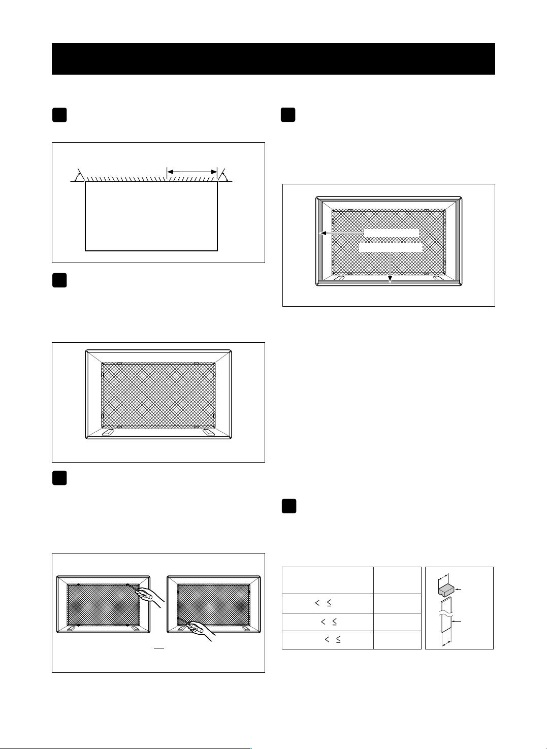
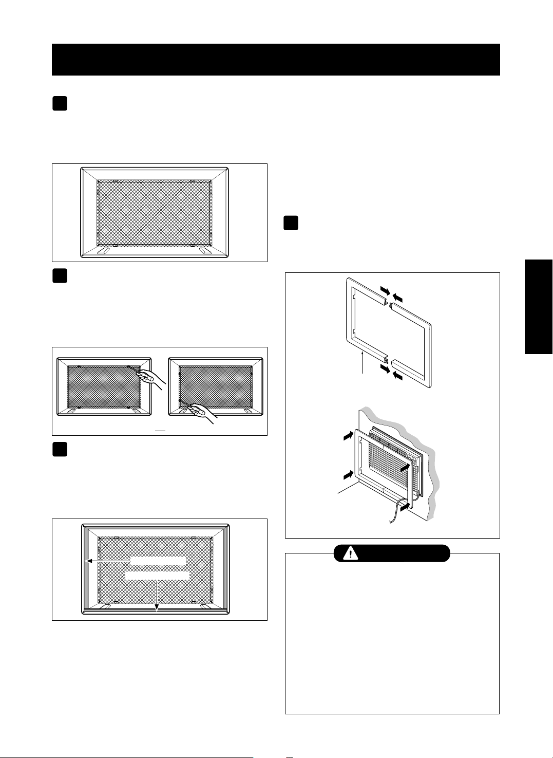
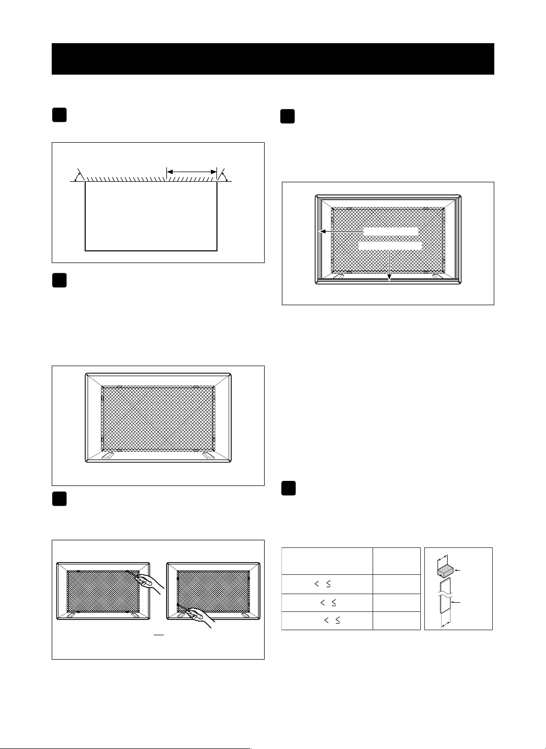
PROCEDURE B
Redirect the louvers at the back of the wall
sleeve to 60° angle as shown in the FIG 7. The
use of pliers is recommended.
If the wall sleeve already has a rear grille, skip
to step 4. If the wall sleeve does not have a rear
grille or louvered panel, install the plastic grille
from the kit. Cut the plastic grille to 25-1/2" wide
and 15-1/4" high. Place the plastic grille to the
inside of the wall sleeve at the rear flange.
Fasten the 4 washer screws to secure the grille
to the wall sleeve. If you need plastic nuts to
mount plastic grille to the inside of the wall
sleeve, there are plastic nuts in the installation
kit. The nuts are installed from the inside of the
sleeve and are pressed into the square holes of
the rear flanges.
Remove the backing from the Horizontal
Insulation strip 1
3
/
8
x
5
/
8
x27
3
/
16
andattachthat
to the inside bottom of the sleeve as shown
below. Remove the backing from the Around
Insulation strip 1
3
/
8
x
3
/
4
x61
1
/
2
andattachthatto
theinsidefrontofthesleeveasshownbelow.
If the depth of your existing wall sleeve is less
than or equal to 18", skip to step 6. Otherwise,
cut the baffles and the support blocks according
to length "A" in the table below.
-8-
INSTALLATION
1
4
2
3
FIG. 8
Around Insulation
Horizontal Insulation
FIG. 10
or
FIG. 9
Rear Louvers
(Top View)
60°
60°
7
5
/
16
"
FIG. 7
Depth"D" of the existing
wall sleeve (inches)
Length "A"
(inches)
Support
Block
Baffle
A
A
3
/4
1-
3
/4
4
18 D 18-
5
/
8
18-
5
/
8
D 19-
3
/
4
19-
3
/
4
D 22
5
Place the plastic grille
Fasten the screws
FIG. 11
-9-
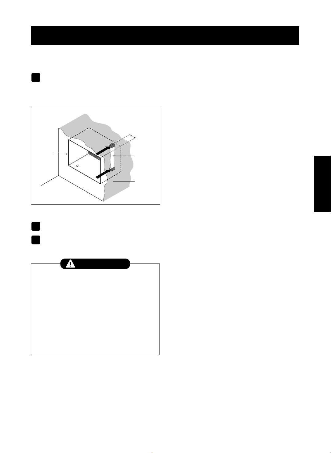
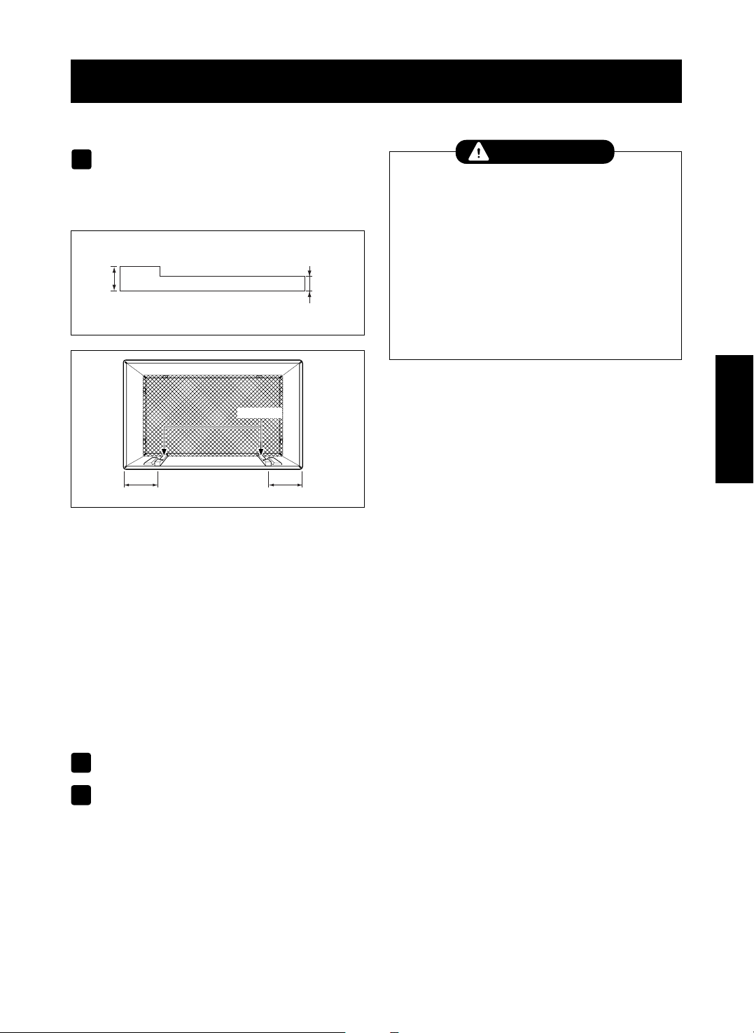
PROCEDURE B
Remove the backing from the support blocks
and attach them to the inside of the wall sleeve
as shown FIG 12. Slide the baffle into slots of
the support blocks.
Install the new unit into the wall sleeve.
Assemble trim as described in Step 5,
Procedure A.
INSTALLATION
6
ENGLISH
Wall
Wall
Sleeve
Baffle
(7
5
/
16
")
Front
Support
Block
FIG. 12
8
7
• Air conditioners covered in this manual pose an
excessive weight hazard. Two or more people are
needed to move and install the unit.
To prevent injury or strain, use proper lifting and
carrying techniques when moving unit.
• When handling the air conditioner, be careful to avoid
cuts from sharp metal fins on front and rear coils.
• Make sure air conditioner does not fall during
removal.
• If unit does not operate after installation check, to be
sure the circuit interrupter has not been tripped. Refer
to the Troubleshooting guide for reset procedure.
CAUTION
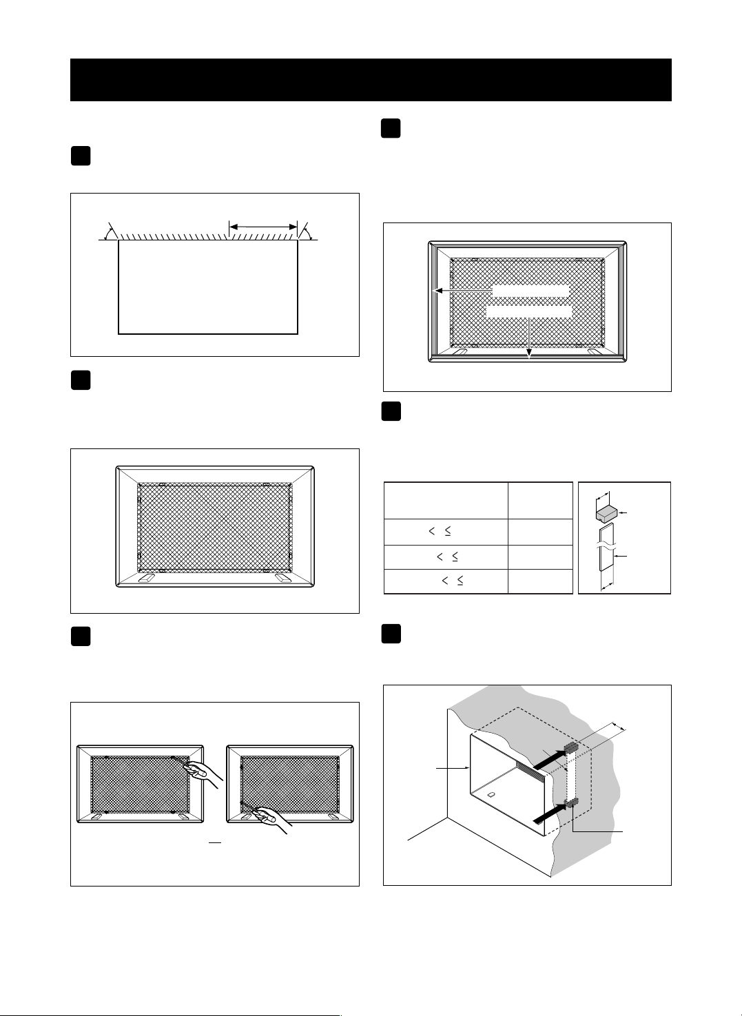
PROCEDURE C
Redirect the louvers at the back of the wall
sleeve to 60° angle as shown in the FIG 13.
The use of pliers is recommended.
If the wall sleeve already has a rear grille, skip
to step 4. If the wall sleeve does not have a rear
grille or louvered panel, install the plastic grille
from the kit. Cut the plastic grille to 26-1/2" wide
and 15-1/2" high. Place the plastic grille to the
inside of the wall sleeve at the rear flange.
Fasten the 4 washer screws to secure the grille
to the wall sleeve. If you need plastic nuts to
mount plastic grille to the inside of the wall
sleeve, there are plastic nuts in the installation
kit. The nuts are installed from the inside of the
sleeve and are pressed into the square holes of
the rear flanges.
Remove the backing from the Horizontal
Insulation strip 1
3
/
8
x1
3
/
8
x27
3
/
16
and attach that
to the inside bottom of the sleeve as shown
below. Remove the backing from the Around
Insulation strip 1
3
/
8
x1
3
/
8
x61
1
/
2
and attach that
to the inside front of the sleeve as shown below.
If the depth of your existing sleeve is less than
or equal to 18”, skip to step 7. Otherwise, cut
the baffles and the support blocks according to
Length "A" in the table below.
Remove the backing from the support blocks
and attach them to the inside of the wall sleeve
as shown FIG 18. Slide the baffle into slots of
the support blocks
Depth"D" of the existing
wall sleeve (inches)
Length "A"
(inches)
Support
Block
Baffle
A
A
3
/4
1-
3
/4
4
18 D 18-
5
/
8
18-
5
/
8
D 19-
3
/
4
19-
3
/
4
D 22
Wall
Wall
Sleeve
Baffle
Front
Support
Block
(
7
13
/
16
"
)
FIG. 18
FIG. 17
-10-
INSTALLATION
1
4
2
3
FIG. 14
Around Insulation
Horizontal Insulation
FIG. 16
or
FIG. 15
Rear Louvers
(Top View)
60°
7
13
/
16
"
60°
FIG. 13
5
6
Place the plastic grille
Fasten the screws
-11-
PROCEDURE C
To achieve rearward slope for unit draining,
remove the backing from the 13" shim strips
and attach them as shown below in Fig. 20.
The higher portion of shim is to be placed in
front of the rib on the base of wall sleeve.
Install the new unit into the wall sleeve
Assemble trim as described in Step 6,
Procedure A.
INSTALLATION
7
ENGLISH
FIG. 19
1" high
3
/
4
" High
Shim (2EA)
6" 6"
FIG. 20
• Air conditioners covered in this manual pose an
excessive weight hazard. Two or more people are
needed to move and install the unit.
To prevent injury or strain, use proper lifting and
carrying techniques when moving unit.
• When handling the air conditioner, be careful to avoid
cuts from sharp metal fins on front and rear coils.
• Make sure air conditioner does not fall during
removal.
• If unit does not operate after installation check, to be
sure the circuit interrupter has not been tripped. Refer
to the Troubleshooting guide for reset procedure.
CAUTION
8
9
-12-
OPERATION
HOW AND WHY
Your room air conditioner provides the following
functions to make hot weather living more
comfortable:
• Cools and circulates room air.
• Lowers humidity by removing excess moisture.
• Filters out summertime dust, dirt, and some
airborne impurities.
The air conditioner performs these functions by
drawing room air through a filter which traps dust
and dirt particles. The air then passes over a
cooling coil which refrigerates the air and removes
excess moisture. The same air is then returned to
the room– cooler, drier, and cleaner. Moisture
removed from the room air is carried to the outside
and evaporated.
Your air conditioner is designed to be easy to
operate and to provide plenty of cooling power.
NORMAL SOUNDS FIG. 21
Aside from the regular fan motor and compressor
sounds coming from your air conditioner, you will
once in a while hear a pinging sound. This is the
result of moisture being picked up from the air in the
room and thrown against the air conditioner's fan.
This is normal and should not be cause for concern.
Also, do not be alarmed if you hear a slight hissing or
gurgling sound coming from your air conditioner after
it is off. These are normal coolant noises.
CAPACITY AND RUNNING TIME
Proper unit size is important in deciding the desired
comfort for the area you want to cool. The proper
size is determined by the number of square feet in
the area to be cooled.
Whenever the heat or humidity load is above normal
the air conditioner must run longer and more often
to keep the desired temperature you have selected.
Under heavy heat load conditions the air conditioner
may need to run constantly to keep the temperature
you want.
At times using the MED FAN setting to circulate the
room air may make it comfortable even though you
do not have the air conditioner set to cool the air.
This will decrease your cost of use.
WATER DRAIN VALVE
When the outside temperature drops below 58°F
and the unit is set for heating, a drain valve opens
up to release water from the base pan. This is
normal and prevents water from freezing in the base
pan and interfering with the outdoor fan.
Fan
You may hear air
movement from the
fan.
Condenser
You may hear
droplets of water
hitting the condenser,
causing a pinging or
clicking sound.
Unit Vibration
The unit may vibrate
and make noise
because of poor wall
or window
construction.
Compressor
The modern high
efficiency compressor
may have a high pitched
hum or pulsating noise
that cycles on and off.
FIG. 21
-13-
ENGLISH
OPERATION
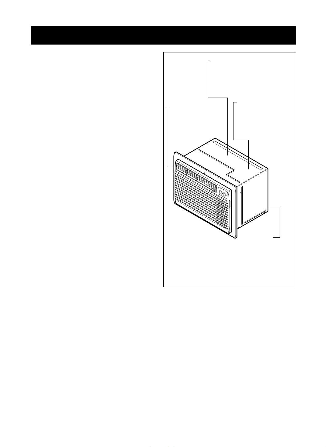
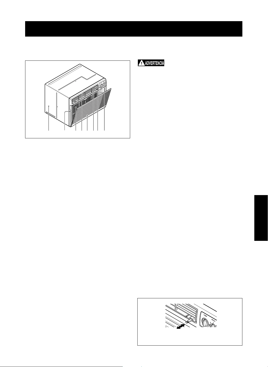
FEATURES
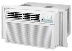
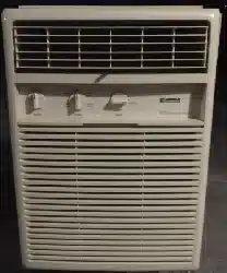
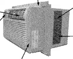
THE UNIT
1. CABINET
2. HORIZONTAL AIR DEFLECTOR
(Vertical Louver)
3. VERTICAL AIR DEFLECTOR
(Horizontal Louver)
4. AIR DISCHARGE
5. FRONT GRILLE
6. INLET GRILLE (Air Intake)
7. AIR FILTER
8. VENT CONTROL
USING THE AIR CONDITIONER
To reduce the risk of fire, electric
shock, or injury to persons, read the important
SAFETY instructions section before operating this
appliance.
To begin operating the air conditioner after
installation, follow these steps:
1. Plug in the air conditioner. (To prevent electrical
hazards, do not use an extension cord or an
adapter plug.)
2. Set the TEMP control to the coolest setting.
3. Set the MODE control at the highest COOL level.
4. Adjust the louvers for comfortable air flow.
5. Once the room has cooled, adjust the TEMP and
MODE control to the setting you find most
comfortable.
NOTE : If the air conditioner is turned off, wait 3
minutes before restarting. This allows pressure
inside the compressor to equalize. Failure to wait 3
minutes before restarting may cause inefficient
operation.
If you move the TEMP control to a warmer, then
immediately back to a cooler setting, the unit will
shut off. Wait 3 minutes before restarting.
Refer to the AIR CONDITIONER FEATURES
section for other settings.
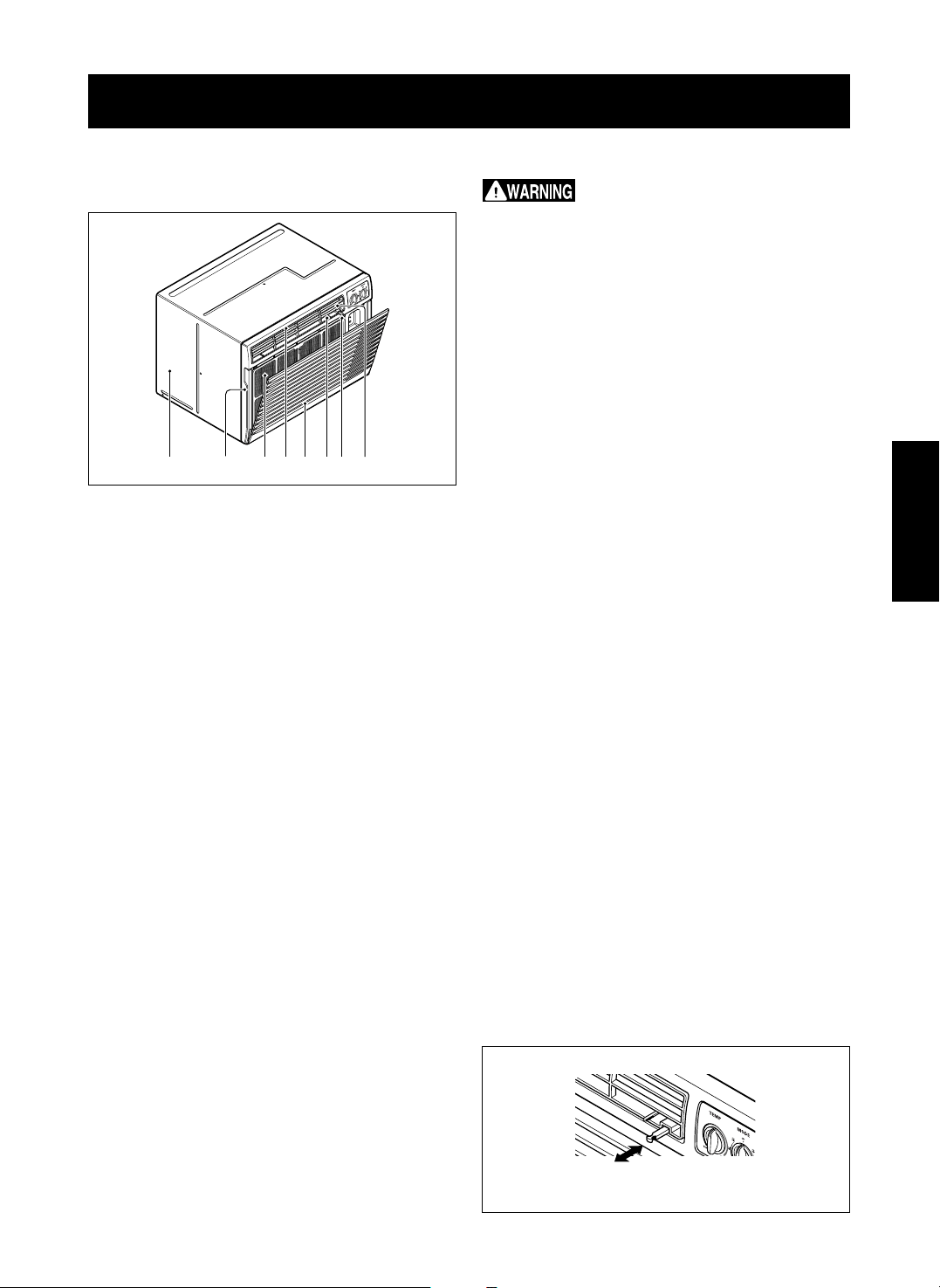
VENT CONTROL
The Vent Control allows the air conditioner to either
recirculate inside air (CLOSE) or exhaust air to the
outside (OPEN). (FIG. 23)
• The CLOSE position is used when maximum
cooling is desired. It may also be used for air
recirculation without cooling when the air
conditioner is set in the FAN position.
• The OPEN position removes stale air from the
room and exhausts it to the outside. Fresh air is
drawn into the room through your home's normal
air passages.
• The OPEN or CLOSE position can be used with
any fan selection.
1 5 67 2 83 4
FIG. 22
PULL OPEN / PUSH CLOSE
FIG. 23
-14-
OPERATION
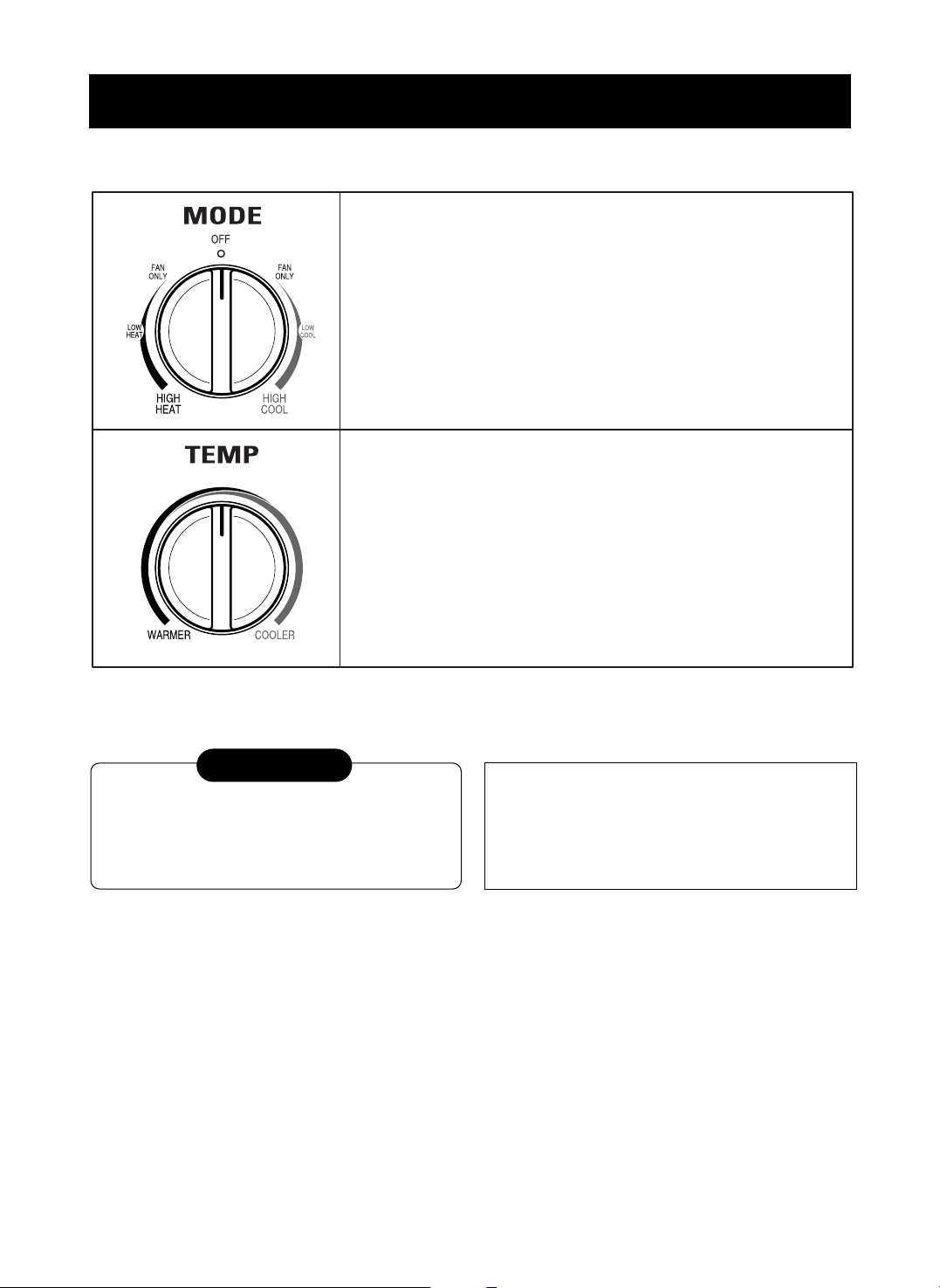
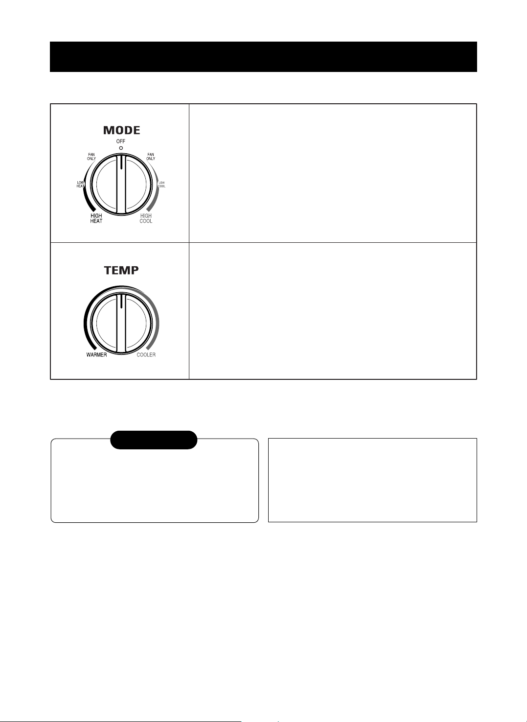
CONTROLS
OFF : Turns air conditioner off.
FAN ONLY : Fan operation without cooling or heating.
LOW COOL : Cooling with low fan speed operation.
HIGH COOL : Cooling with high fan speed operation.
LOW HEAT : Heating with low fan speed operation.
HIGH HEAT : Heating with high fan speed operation.
Turn the Temperature Knob to the desired setting.
The central position is a normal setting for average conditions.
You can change this setting, if necessary, in accordance with your
temperature preference.
The thermostat automatically controls cooling or heating, but the fan
runs continuously whenever the air conditioner is in operation.
If the room is too warm, turn the thermostat control clockwise.
If the room is too cool, turn the thermostat control counterclockwise.
The compressor will turn on and off to keep the room at the set temperature.
In the heating operation, the electric heater will turn on and off to keep the room at the set temperature.
When the air conditioner has been operated in the
cooling or heating mode and is turned off or set to
the fan position, wait at least 3 minutes before
resetting to the cooling operation again.
CAUTION
A slight burning odor may come from the
unit when first switching to HEAT after the
cooling season is over. This odor, caused
by fine dust particles on the heater, will
disappear quickly. This is normal operation.
-15-
OPERATION
HORIZONTAL AIR-DIRECTION
ADJUSTMENT
• The horizontal air direction is adjusted by moving
vertical louver.
• The vertical louver control levers are located in the
right and left side of the air discharge.
VERTICAL AIR-DIRECTION ADJUSTMENT
• The vertical air direction is adjusted by moving the
horizontal louvers.
FIG. 24
FIG. 25
ENGLISH
-16-
MAINTENANCE
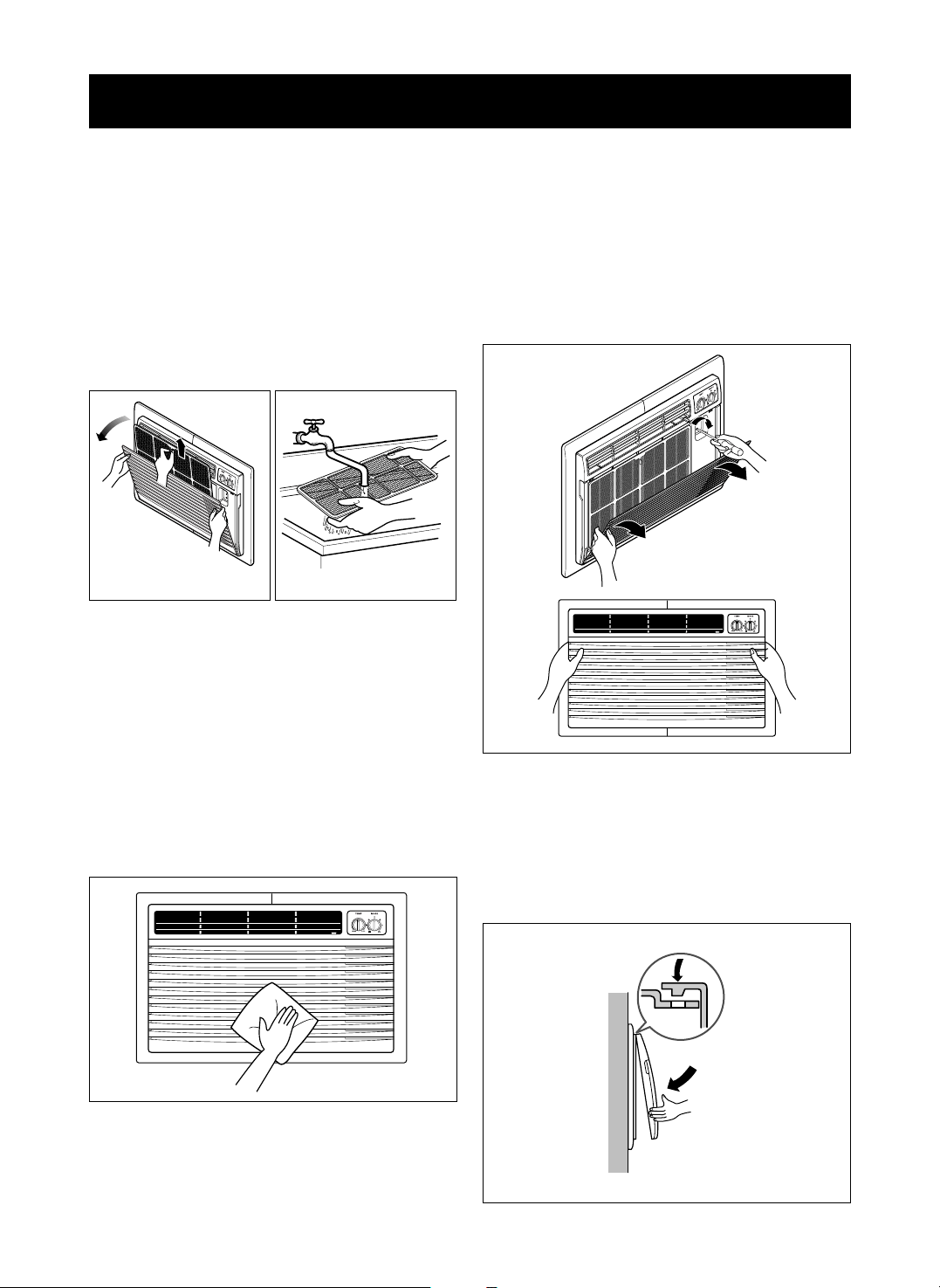
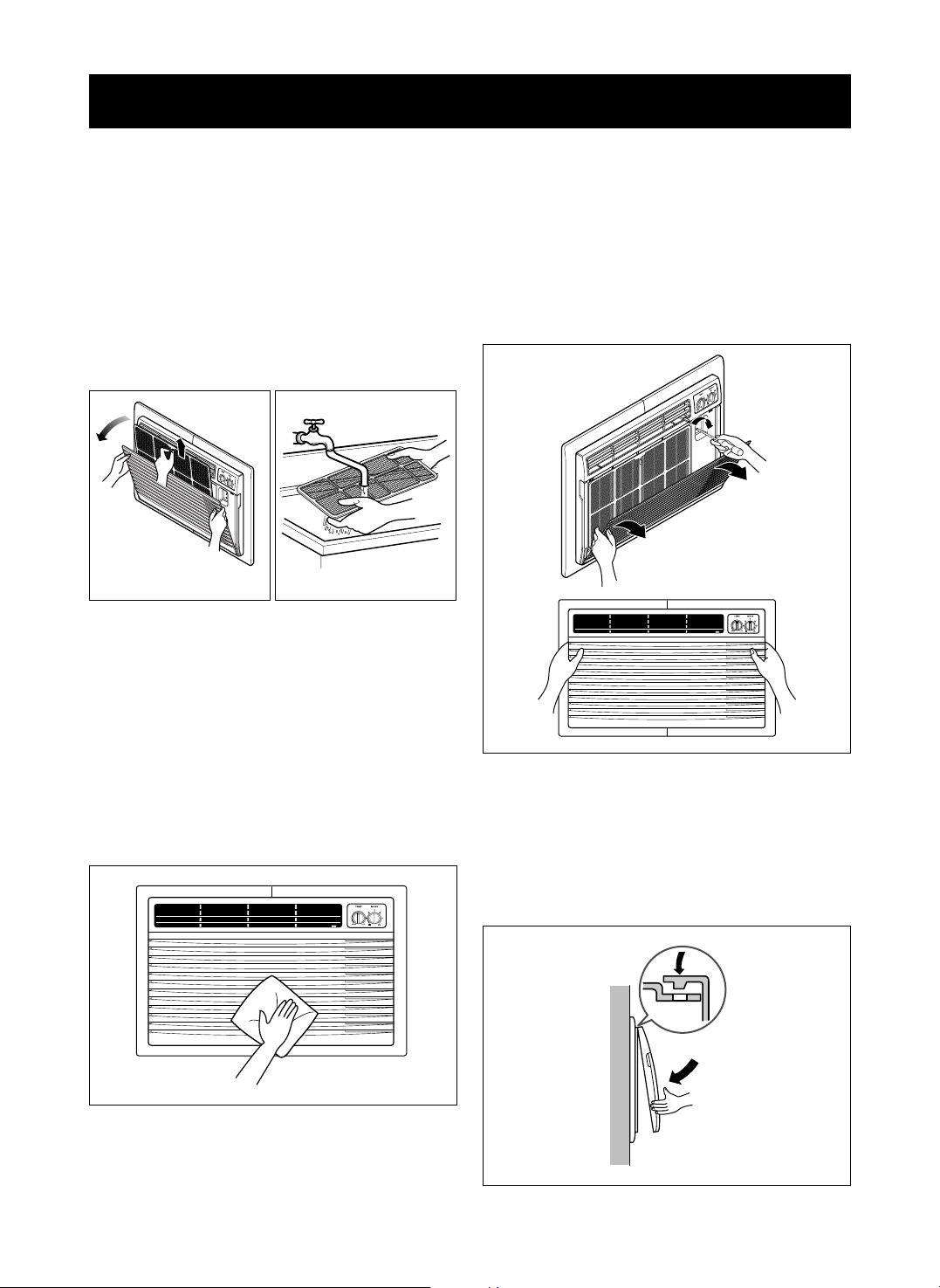
AIR FILTER CLEANING
The Air Filter will become dirty as it removes dust
from the inside air. It should be washed at least
every 2 weeks. If the Air Filter remains full of dust,
the air flow will decrease and the cooling capacity
will be reduced, possibly damaging the unit.
• Pull the inlet grille forward and pull out the air filter.
(FIG. 26)
• Wash the Air Filter under the faucet with warm
water. Be sure to shake off all the water before
replacing the filter. (FIG. 27)
AIR CONDITIONER CLEANING
Clean the front grille and inlet grille by wiping with a
cloth dampened in a mild detergent solution.
The cabinet may be washed with mild soap or
detergent and lukewarm water, then polished with
liquid appliance wax.
To ensure continued peak efficiency, the condenser
coils (outdoor side of the unit) should be checked
periodically and cleaned if they become clogged
with soot or dirt from the atmosphere. Brush or
vacuum exterior coils to remove debris from fins.
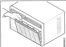
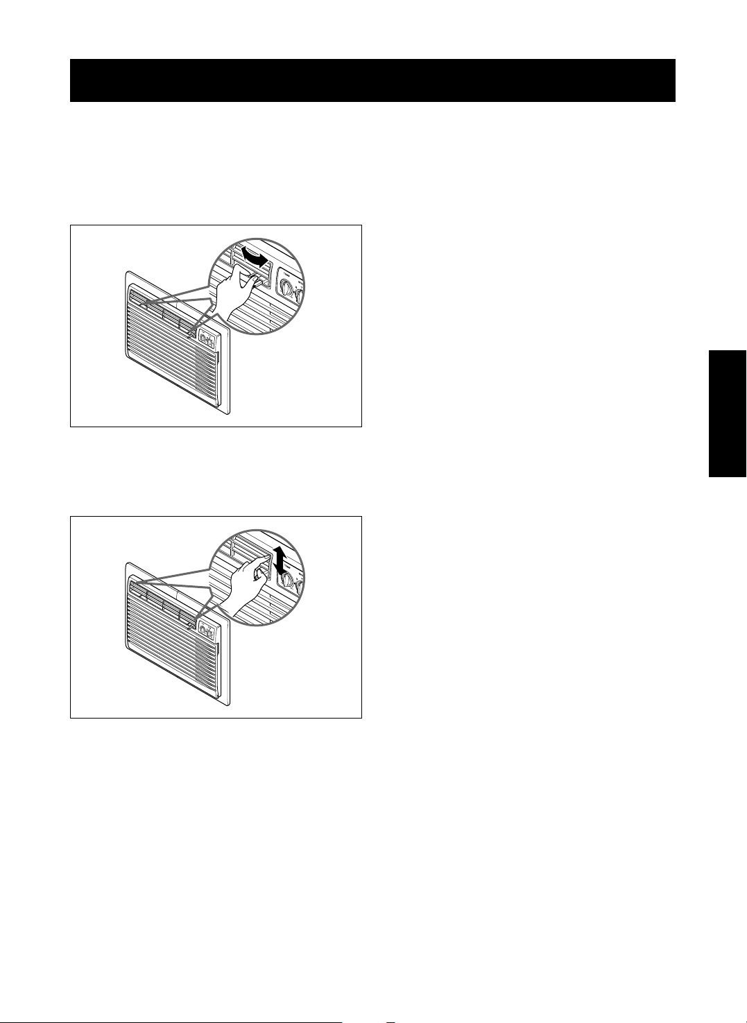
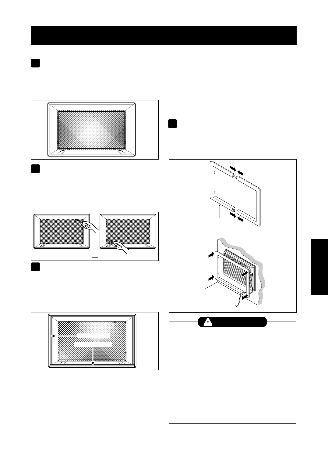
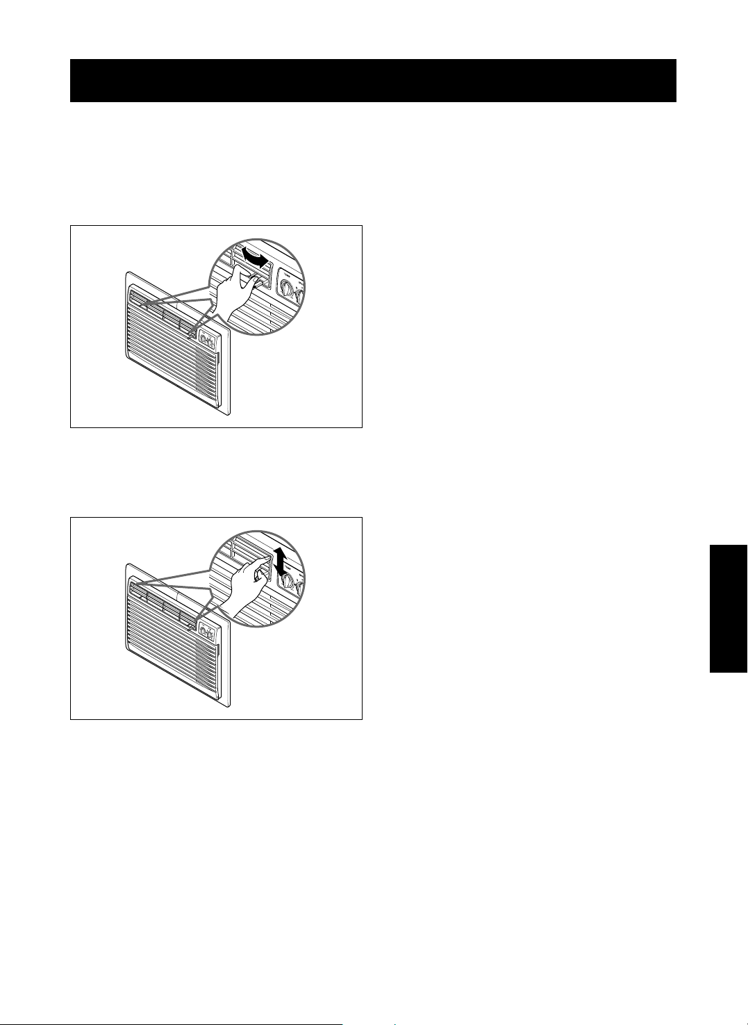
HOW TO REMOVE THE FRONT
GRILLE
• Open the inlet grille.
• Remove the screw securing the Front Grille.
• Push the grille up from the bottom and pull the top
of the grille away from the case to lift the top tabs
outoftheirslots.
HOW TO REPLACE THE
FRONT GRILLE
Attach the front grille to the cabinet by inserting the
tabs on the grille into the slots on the front of the
cabinet. Push the grille in until it snaps into place.
FIG. 29
FIG. 30
FIG. 26 FIG. 27
FIG. 28
-17-
ENGLISH
THE AIR CONDITIONER WILL NOT OPERATE.
Check if... Then...
Wall plug disconnected. Push plug firmly into wall outlet.
House fuse blown or circuit breaker tripped. Replace fuse with time delay type or reset circuit breaker.
Power is OFF. Push the power button.
Unit was turned off and then on too quickly. Set unit off and wait 3 minutes before restarting.
TEMP Control set warmer than room temperature.
Turn TEMP Control clockwise to a cooler setting.
THE AIR CONDITIONER COOLING, BUT ROOM IS TOO WARM.
Check if... Then...
Dirty air filter – air restricted. Clean air filter. Refer to Maintenance section of owner's manual.
TEMP Control set too warm. Turn TEMP control clockwise to a cooler setting.
Front of unit is blocked by drapes, blinds, furniture, etc. Clear blockage in front of unit.
Air distribution is restricted.
Doors, windows, registers, etc. open. Cold air escapes. Close doors, windows, registers, etc.
Unit recently turned on in hot room. A
llow additional time to remove stored heat from walls, ceiling, floor, and furniture.
THE AIR CONDITIONER TURNS ON AND OFF RAPIDLY.
Check if... Then...
NOISE WHEN UNIT IS COOLING.
Check if... Then...
Sound of fan hitting water – from the moisture removal system.
This is normal when humidity is high. Close doors, windows, and registers.
Window vibration – poor installation. Refer to installation instructions or check with installer.
WATER DRIPPING INSIDE ROOM WHEN UNIT IS COOLING.
Check if... Then...
The air conditioner is improperly installed. Tilt air conditioner slightly to the outside to allow water drainage. Refer to
installation instructions or check with installer.
WATER DRIPPING OUTSIDE WHEN UNIT IS COOLING.
Check if... Then...
The unit is removing large quantities of moisture This is normal during excessively humid days.
from humid room.
AIR FROM UNIT DOES NOT FEEL COLD ENOUGH.
Check if... Then...
MODE selector in LOW COOL position.
TEMP Control set too warm.
Room temperature below 70°F (21°C) Cooling may not occur until room temperature rises above 70°F (21°C).
Temperature sensing tube touching evaporator coil, Straighten tube away from evaporator coil.
located behind front grille.
Turn selector to HIGH COOL position
Turn TEMP Control clockwise to a cooler setting.
THE AIR CONDITIONER COOLING, BUT ROOM IS TOO WARM – ICE FORMING ON COOLING COIL BEHIND INLET GRILLE.
Check if... Then...
Outdoor temperature below 70°F (21°C).
Air filter may be dirty. Clean air filter. Refer to Maintenance section of owner's manual.
TEMP Control set too low.
To defrost the coil, set selector to FAN position.
To defrost the coil, set selector to a FAN position.
Outside temperature is extremely hot.
Set MODE on HIGH COOL to bring air past cooling coils faster.
The Current interrupter Device is tripped. Press the RESET button located on the power cord plug.
If the RESET button will not stay engaged, discontinue use of the air
conditioner and contact a qualified service technician.
TROUBLESHOOTING
BEFORE CALLING FOR SERVICE
Check the following list to be sure a service call is really necessary. A quick reference to this manual may
help you avoid an unneeded service call.

-18-
ÍNDICE
GARANTÍA
-18-
GARANTÍA COMPLETA DE UN AÑO DEL
APARATO DE AIRE ACONDICIONADO DE
PARED
Durante un año, a contar a partir de la fecha de compra, cuando
este aparato de aire acondicionado funcione para el enfriamiento
normal de una habitación y reciba mantenimiento, todo ello
según las instrucciones de este Manual del propietario, Sears
reparará este aparato de aire acondicionado, de forma gratuita, si
tuviera algún defecto de fabricación o materiales.
EL SERVICIO DE GARANTÍA PUEDE
CONTACTARSE EN EL SERVICIO DE ATENCIÓN
AL CLIENTE DE SEARS EN EL 1-800-4-MY-HOME
®
.
Esta garantía se aplica sólo durante el uso de este producto en
los Estados Unidos.
Esta garantía le concede derechos legales específicos y puede
que usted tenga otros derechos adicionales que varían según el
estado.
Distributed by Sears, Roebuck and
Co., Hoffman Estates, IL 60179
ÍNDICE
......................................................
18
GARANTÍA
..............................................
18
SEGURIDAD
...........................................
19
Instrucciones importantes de seguridad
...
19
REQUISITOS ELÉCTRICOS
.............
20
INSTALACIÓN
........................................
21
Requisitos de instalación
.......................
21
Instalación
..............................................
22
Procedimiento A.....................................23
Procedimiento B.....................................24
Procedimiento C.....................................26
FUNCIONAMIENTO
.............................
28
Cómo y por qué
......................................
28
Sonidos normales
..................................
28
Capacidad y tiempo de funcionamiento
....
28
Características
.......................................
29
Uso del aparato de aire acondicionado
.....
29
Características del aparato de aire
acondicionado
........................................
30
MANTENIMIENTO
................................
32
Limpieza del filtro de aire
.......................
32
Limpieza del aparato de aire
acondicionado
........................................
32
Cómo extraer la rejilla frontal
.................
32
Cómo volver a colocar la rejilla frontal ...32
RESOLUCIÓN DE PROBLEMAS
....
33
Antes de llamar al servicio técnico
.........
33
ACUERDOS DE PROTECCIÓN
ESPECIALIZADA
..................................
35
NÚMEROS DE SERVICIO
TÉCNICO
..................................
Contraportada
-19-
ESPAÑOL
SEGURIDAD
INSTRUCCIONES IMPORTANTES DE SEGURIDAD
Las instrucciones de seguridad que se indican abajo le dirán cómo utilizar su aparato de aire acondicionado
para evitar daños a sí mismo y daños a su APARATO DE AIRE ACONDICIONADO.
PARA SU SEGURIDAD
No almacene ni utilice gasolina ni otros líquidos ni gases
inflamables cerca de éste u otro electrodoméstico. Lea
las etiquetas de los productos para conocer su
inflamabilidad y otras advertencias.
EVITAR ACCIDENTES
Para reducir el riesgo de incendio, electrocución o heridas a
personas al utilizar su aparato de aire acondicionado, siga
las precauciones básicas, incluyendo las siguientes:
• Asegúrese de que el servicio eléctrico es adecuado para el
modelo que ha escogido.
• Si el aire acondicionado va a instalarse en una ventana,
sería conveniente que limpiara primero ambos lados del
cristal. Si la ventana tiene tres guías de deslizamiento, con
un panel pantalla incluido, puede que desee extraer
completamente la pantalla antes de la instalación.
• Asegúrese de que el aparato de aire acondicionado se ha
instalado de modo seguro y correcto según las
instrucciones en este Manual. Guarde este manual y las
instrucciones de instalación para su posible uso futuro para
extraer o volver a instalar esta unidad.
• Utilice guantes cuando maneje el aparato de aire
acondicionado. Preste atención para evitar cortes de las
afiladas aletas de metal en las bobinas frontal y posterior.
INFORMACIÓN ELÉCTRICA
El valor nominal eléctrico completo de su nuevo aparato de aire
acondicionado se especifica en su etiqueta identificativa.
Consulte el valor nominal al comprobar los requisitos eléctricos.
• Asegúrese de que el aparato de aire acondicionado tiene
una toma de tierra adecuada. Para reducir al mínimo el
riesgo de electrocución y de incendio, es importante tener
una toma de tierra adecuada. El cable de alimentación está
equipado con un enchufe de tres clavijas con toma a tierra
para proteger contra electrocución.
• Su aparato de aire acondicionado debe estar enchufado a
un enchufe de pared con una toma de tierra adecuada. Si
el enchufe que quiere utilizar no tiene una toma de tierra
adecuada o no está protegido por un fusible temporizado o
un interruptor de corriente, haga que un electricista
cualificado instale el enchufe apropiado.
• No haga funcionar el aparato de aire acondicionado con la
lámina de embalaje en la parte posterior del alojamiento o
con la cinta azul y las esquineras del aparato de aire
acondicionado. Esto podría tener como consecuencia la
producción de daños mecánicos al aparato de aire
acondicionado.
• No utilice un cable extensor ni un enchufe adaptador.
IDEAS PARA AHORRAR ENERGÍA
• La capacidad del aparato de aire acondicionado debe
ser adecuada al tamaño de la habitación para un
funcionamiento eficaz y satisfactorio.
• Instale el aparato de aire acondicionado en el lado de su
hogar a la sombra. Una ventana que mira al norte es la
mejor porque se encuentra a la sombra la mayor parte
del día.
• No bloquee el flujo del aire en el interior con persianas,
cortinas o muebles, ni en el exterior con arbustos,
cercas u otros edificios.
• Cierre las aperturas en suelo y ventanas y el tiro de la
chimenea para que el aire frío no salga por la chimenea
ni por los conductos.
• Mantenga cerradas las persianas y cortinas de otras
ventanas durante la parte más soleada del día.
• Limpie el filtro de aire según se recomienda en la
sección de MANTENIMIENTO de este manual.
• El aislamiento adecuado y la preparación de su hogar
para las condiciones atmosféricas mantendrán el aire
caliente en el exterior y el aire frío en el interior.
• La existencia de sombra en el exterior de la casa con
árboles, plantas o toldos reduce la carga de trabajo del
aparato de aire acondicionado.
• Haga funcionar los electrodomésticos que produzcan
calor, como cocinas, lavadoras, secadoras y lavavajillas,
durante la parte más fría del día.
Enchufe de
pared del tipo
puesta
a tierra
Bajo ninguna
circunstancia corte,
desmonte o puentee el
diente de puesta a tierra
de este enchufe.
Cable de alimentación
con enchufe de puesta a
tierra de tres dientes
Reponga
Prueba
Evite los peligros de incendio o de electrocución.
No utilice un cable extensor ni un enchufe adaptador.
No quite ninguna clavija del cable de alimentación.
-20-
REQUISITOS ELECTRICOS
RESPETE TODOS LOS CÓDIGOS Y
REGLAMENTOS.
BAJO NINGUNA CIRCUNSTANCIA CORTE,
QUITE O EVITE EL USO DE LA CONEXIÓN A
TIERRA DE ESTA CLAVIJA.
LA TOMA A TIERRA ES NECESARIA EN ESTE
ELECTRODOMÉSTICO.
Es necesaria una fuente de alimentacióneléctrica
de 208/230 voltios, 60 Hz y 115-voltios, 60 Hz, sólo
AC, con fusible de 15 A y correctamente puesta a
tierra. Se recomienda el uso de un fusible o
interruptor de retardo. Utilice un circuito dedicado,
únicamente para este electrodoméstico.
NO USE CABLE ELÉCTRICO DE EXTENSIÓN.
MÉTODO RECOMENDADO DE CONEXIÓN A
TIERRA
Por su propia seguridad este aparato debe
conectarse a tierra. Este aparato viene equipado
con un cable de alimentación y una clavija de tres
terminales. Para reducir al máximo el peligro de
choque eléctrico, el cable debe estar conectado a
una conexión de pared con conexiónatierra,yesta
conexión debe hacerse de acuerdo con la última
edicióndelCódigo Eléctrico Nacional (ANSI/NFPA
70), así como con los códigos y reglamentos
locales. Si no existe una conexióndepared
adecuada, el cliente tiene la responsabilidad y la
obligación de mandar instalar, con un electricista
calificado, una conexióndeparedadecuadadetres
terminales con conexiónatierra.
115V~ 230V~
El cable de alimentación puede incluir un dispositivo
interruptor de corriente. La carcasa del enchufe cuenta
con un botón de prueba y otro de reinicio. El dispositivo
debe comprobarse periódicamente presionando
primero el botón TEST y después RESET.
Si el botón TEST no se desconecta o si el botón
RESET no permanece activo, suspenda el uso del aire
acondicionado y póngase en contacto con un técnico
de servicio cualificado.
Peligro de choque eléctrico
Conecte en una conexión de pared de 3 terminales
No quite la terminal de conexión a tierra
No use adaptadores
No use cable eléctrico de extensión
Si no se siguen estas instrucciones, puede ocasionarse
la muerte, un incendio o un choque eléctrico.
Utilice el enchufe de la pared
Consumo de Energía
Standard 125V,
enchufe de 3
Líneas de
15A, 125V AC
Standard 250V,
enchufe de 3
Líneas de
15A, 250V AC
Utilice un fusible de
15AMP. o un
Interruptor de 15AMP.
Utilice un fusible de
20AMP. o un
Interruptor de 20AMP.
Standard 250V,
enchufe de 3
Líneas de
20A, 250V AC
ADVERTENCIA
NOTA: La forma puede ser diferente según su modelo.
Enchufe de puesta a
tierra de 3 dientes
Diente de
puesta a tierra
Cable de
alimentación
(208/230-voltios 60 Hz)
Enchufe de
pared del tipo
de puesta a
tierra de 3
dientes
Reponga
Prueba
(115-voltios 60 Hz)
-21-
ESPAÑOL
INSTALACIÓN
REQUISITOS DE INSTALACIÓN
Si utiliza un alojamiento de pared existente, debe tomar sus
medidas.
Instale el nuevo aparato de aire acondicionado segúnestas
instrucciones de instalación para conseguir el mejor rendimiento.
Todos los alojamientos de pared utilizados para montar el nuevo
aparato de aire acondicionado deben tener su estructura en
buenas condiciones y tener una rejilla posterior para fijar con
seguridad el nuevo aparato de aire acondicionado. (FIG.1)
Con el alojamiento Kenmore, puede mantener el máximo
rendimiento de su nuevo aparato de aire acondicionado.
SERVICIO ELECTRICO
Compruebe el servicio eléctrico disponible. La alimentación
disponible debe coincidir con la que se muestra en la etiqueta
identificativa de la unidad (que se encuentra en el lado izquierdo
del alojamiento).
Todos los modelos están equipados con un enchufe de servicio
de 3 clavijas con una toma de tierra positiva segura. No
modifique el enchufe de ninguna manera. No utilice un enchufe
adaptador. Si su toma de corriente en la pared no coincide con el
enchufe, llame a un electricista cualificado para realizar los
cambios necesarios. GUARDE LA CAJA para el almacenamiento
y esta GUÍA DEL PROPIETARIO para futura referencia. La caja
es la mejor manera de almacenar la unidad durante el invierno o
cuando no se utilice.
EQUIPO DE INSTALACIÓN
14-
13
/
32
"
(366 mm)
24-
21
/
32
"
(626 mm)
18"(458 mm)
19-
21
/
32
"
(499 mm)
Para evitar peligro de heridas personales, daños a la propiedad o
al producto debido al peso de este aparato y a los bordes
afilados que pueden estar expuestos:
• Los aparatos de aire acondicionado de los que trata este
manual constituyen un peligro de peso excesivo. Se necesitan
dos o más personas para mover e instalar la unidad. Para evitar
heridas o problemas musculares, utilice técnicas adecuadas
para elevar y desplazar la unidad.
•
Revise cuidadosamente la ubicación donde se instalará el aparato
de aire acondicionado. Asegúrese de que puede soportar el peso
de la unidad durante un periodo de tiempo prolongado.
• Maneje con cuidado el aparato de aire acondicionado. Lleve
guantes protectores siempre que levante o desplace la unidad.
EVITE las aletas afiladas de metal de las bobinas frontal y
posterior.
• Asegúrese de que el aparato de aire acondicionado no cae al
suelo durante la instalación.
CUIDADO
HERRAMIENTAS NECESARIAS:
• Guantes ajustados
• Destornillador estándar
• Destornillador Phillips
• Cuchillo afilado
• Cinta para medir
•
Llaveajustableodeextremo
abiertode0,96cm(3/8depulgada)
• Llave articulada
• Llave de cabeza hexagonal de
0,64 cm (1/4 de pulgada) y
trinquete
• Taladro eléctrico
• Broca de taladro de 0,64 cm
(1/4 de pulgada)
FIG. 1
Aparato de aire acondicionado
1
4
5
6
7
3
2
8
2 opciones de tamaño
2 opciones de tamaño
ARTÍCULO
NOMBRE DE LAS PIEZAS
CANTIDAD
REJILLADEPLÁSTICO 1
TIRAS DE AISLAMIENTO HORIZONTAL 2
TIRASDEAISLAMIENTOLATERAL 2
BLOQUE DE SOPORTE 2
DEFLECTOR 1
BASTIDOR DE REBORDE 2
CALZO PARA AJUSTE 2
TUERCASDEPLÁSTICOYTORNILLOSDEARANDELA
4
-22-
INSTALACIÓN
INSTALACIÓN
•
Si decide mantener el alojamiento de pared existente, tendrá que ajustar la
dirección de la rejilla en la parte posterior de la ilustración del alojamiento
de pared. Se recomienda el uso de tenazas. Si NO ajusta la dirección,
corre el riesgo de un rendimiento pobre o de fallo del producto. Este hecho
no está cubierto bajo los términos de la garantíadeKENMORE.
ARTÍCULOSENELEQUIPODEINSTALACIÓN
Puede que no necesite todas las partes del equipo de
instalación. Tire las piezas que no utilice.
CÓMO INSTALARLO
Identifique el alojamiento existente en la pared antes de
instalar la unidad de la lista que se muestra a continuación
NOTA: Todos los alojamientos de pared utilizados para montar
el nuevo aparato de aire acondicionado deben estar en buenas
condiciones estructurales y tener una rejilla posterior que se una
con seguridad al alojamiento o un flanco posterior que sirva de
tope al aparato de aire acondicionado,
Extraiga el antiguo aparato de aire acondicionado del
alojamiento de pared ya existente.
Limpie el interior del alojamiento de pared ya existente.
(No toque los sellados.)
El alojamiento de pared debe estar bien fijado a la pared
antes de instalar el aparato de aire acondicionado. Si fuera
necesario, utilice los clavos o tornillos para fijar el
alojamiento a la pared.
- Vuelva a pintar el alojamiento si fuera necesario.
Prepare el alojamiento de pared para la instalacióndelaunidad.Si
piensa utilizar el alojamiento ya existente, y no es de la marca Kenmore,
utilice los procedimientos B o C que se explican a continuación.
Instale la nueva unidad en el alojamiento de la pared.
PRECAUCIÓN:
Al finalizar la instalación, la unidad de
sustitución DEBE tener una pendiente hacia atrássegún
se ilustra. Para lograr una pendiente de 1/4", retire el
envoltorio de las cuñas de 13" y acóplelas segúnse
muestra a continuación en la FIG. 2. Coloque el extremo
másaltodelacuña en la parte frontal de la base del
soporte de pared.
1
2
3
4
5
6
Se recomienda encarecidamente la extraccióndelantiguo
alojamiento de la pared y la instalacióndeunalojamiento
plegable de la pared Kenmore nuevo.
Si decide mantener el alojamiento de pared existente, tendrá
que ajustar la dirección de la rejilla en la parte posterior de la
ilustración del alojamiento de pared. Se recomienda el uso de
tenazas. Si NO ajusta la dirección, corre el riesgo de un
rendimiento pobre o de fallo del producto. Este hecho no está
cubierto bajo los términos de la garantía de KENMORE.
ADVERTENCIA
ARTÍCULO
Cantidad
Rejilla de plástico 3,81 x 2,54 x 210,03 cm (26
3
/4 x16
1
/2)1
Tiras de aislamiento horizontal
3,5 x 1,52 x 69,03 cm (1
3
/8 x
5
/8 x27
3
/16)1
3,5 x 3,5 x 69,03 cm (1
3
/8 x1
3
/8 x27
3
/16)1
Tiras de aislamiento lateral
3,5 x 2,03 x 153,035 (1
3
/8 x
3
/4 x61
1
/2)1
3,5 x 3,5 x 153,035 (1
3
/
8 x1
3
/
8 x61
1
/
2)1
Bloque de soporte 8,89 x 3,5 x 10,94 cm (1
3
/4 x1
3
/8 x4
5
/16)2
Deflector 35,56 x 11,43 x 0,33 (14 x 4
1
/
2 x
1
/
8)1
Calzo para ajuste 33,02 x 2,54 x 2,03 (13 x 1 x
3
/4)2
Bastidor de reborde 2
Tornillo de arandela 4
Tuercas (plástico) 4
Parte posterior de la rejilla 1
Marca
Anchura
64,77
(25-1/2)
38,73
(15-1/4)
66,04(26) 39,70(15-5/8) 42,87(16-7/8)
65,48(25-7/8) 41,91(16-1/2)
43,51 o 58,42
(17-1/8 o 23)
68,58(27) 42,54(16-3/4)
65,73 (25-7/8)
39,44 (15-17/32) 42,46 (16-23/32)
67,94 (26-3/4)
40 (15-3/4) 38,1 (15)
65,40 (25-3/4) 42,87 (16-7/8) 47,32 (18-5/8)
68,58 (27)
42,54 (16-3/4) 42,54 (16-3/4)
42,54 o 50,16
(16-3/4 o 19-3/4)
40,64, 44,45, 55,88
(16, 17-1/2)
Altura Profundidad
Medidas del alojamiento de la pared
(pulgadas y centímetros)
White-Westinghouse
Frigidaire
Carrier (Serie 52F)
General Electric/Hotpoint
Whirlpool
Fedders/Emerson
Sears/Kenmore
Emerson/Fedders
Carrier (Serie 51S)
Friedrich
Procedimiento
Marca Profundidad
Sears/Kenmore
White-Westinghouse
Frigidaire Carrier
(52F series)
General Electric
/Hotpoint
Whirlpool
Carrier (51S series)
Fedders/Emerson
Emerson/Fedders
Friedrich
40,64, 44,45 0 55,88
(16, 17-1/2 o 22)
42,44 (16-23/32)
42,87 (16-7/8)
42,54 o 50,16 (16-3/4 o 19-3/4)
43,5 o 58,42 (17-1/8 o 23)
47,29 (18-5/8)
38,1 (15)
42,54 (16-3/4)
B
A
C
1/4"
Soporte
de pared
FRENTAL
UNIDAD
COLOCACIÓN DE LA CUÑA INSTALACIÓN DE LA UNIDAD
1"de
alto
3/4"de alto
Cuña
6" 6"
FIG. 2
-23-
ESPAÑOL
INSTALACIÓN
PROCEDIMIENTO A
Si está utilizando un nuevo soporte de pared
(incluido opcionalmente con su unidad), salte al paso
3. Si no es así, instale la rejilla plástica. Corte la
rejilla plástica a 25-1/2" de ancho y 15-1/4” de alto.
Coloque la rejilla plástica en el interior del soporte de
paredenlapestañaposterior.
Apriete los 4 tornillos de arandela para fijar la rejilla
al alojamiento de pared. Si necesita tuercas de
plástico para montar la rejilla de plástico en el interior
del alojamiento, hay tuercas de plástico en el equipo
de instalación. Las tuercas se instalan desde el
interior del alojamiento y se introducen apretándolas
en los orificios cuadrados de los flancos traseros.
Extraiga la parte posterior de la tira de Aislamiento
horizontal de 3,5 x 0,96 x 69,06 cm (1
3
/8 x
3
/5 x
27
3
/
16)yfíjela a la parte inferior interna del
alojamiento según se muestra abajo. Extraiga la
parte posterior de la tira de Aislamiento lateral de 3,5
x1,9x156,21cm(1
3
/8 x
3
/4 x61
1
/2)yfíjela al interior
del alojamiento según se muestra abajo.
Para montar el reborde, inserte el saliente de cada
pieza en la ranura de la otra pieza segúnsemuestra
abajo. Deslice el reborde sobre la parte frontal del
aparato de aire acondicionado hasta que el reborde
esté unido a paño con el alojamiento segúnse
muestra a continuación.
FIG. 3
Aislamiento lateral
Aislamiento horizontal
FIG. 5
O
FIG. 4
1
2
3
4
Pared
Adorno (2ea)
FIG. 6
• Los aparatos de aire acondicionado de los que trata
este manual constituyen un peligro de peso excesivo.
Se necesitan dos o máspersonasparamovere
instalar la unidad. Para evitar heridas o problemas
musculares, utilice técnicas adecuadas para elevar y
desplazar la unidad.
• Al manejar el aparato de aire acondicionado, tenga
cuidado de evitar cortes de las aletas afiladas de metal
en las bobinas frontal y trasera.
• Asegúrese de que el aparato de aire acondicionado no
se cae durante la instalación.
• Si la unidad no funciona tras la revisióndeinstalación,
asegúrese que el interruptor del circuito no se ha
disparado. Consulte la guía de solución de averías
para conocer el procedimiento de reinicio.
CUIDADO
-24-
PROCEDIMIENTO B
Coloque la dirección de la rejilla en la parte posterior del
alojamiento de la pared en un ángulode60° segúnse
muestra en la FIG 7. Se recomienda el uso de tenazas.
Si el alojamiento de pared está ya equipado con una
rejilla trasera, pase directamente al paso 4. Si el
alojamiento de la pared no tiene una rejilla posterior ni
un panel con lamas, instale la rejilla de plástico del
equipo de instalación. Corte la rejilla de plásticoaunas
medidas de 64,77 cm (25-1/2) de ancho y 38,74 cm
(15-1/4) de alto. Coloque la rejilla de plásticoenel
interior del alojamiento de pared en el flanco posterior.
Cuando el alojamiento de la pared tiene una rejilla
posterior de panel con lamas, salte al paso 3 y omita
el paso 4. Coloque la rejilla de plástico en el interior
del alojamiento de pared en el flanco posterior.
Extraiga la parte posterior de la tira de Aislamiento
horizontal de 3,5 x 1,60 x 69,06 cm (1
3
/8 x
5
/8 x27
3
/16
)yfíjela
a la parte inferior interna del alojamiento según se muestra
abajo. Extraiga la parte posterior de la tira de Aislamiento
lateral de 3,5 x 1,9 x 156,21 (1
3
/8
x
3
/4
x61
1
/2
)yfíjela al
interior del alojamiento según se muestra abajo.
Cuando la profundidad del alojamiento existente es
igual o menor a 45,72 cm (18 pulgadas), pase
directamente al paso 6. En caso contrario, corte los
deflectores y los bloques de soporte segúnla
longitud “A” de la tabla que se muestra abajo.
INSTALACIÓN
1
4
2
3
FIG. 8
Aislamiento lateral
Aislamiento horizontal
FIG. 10
O
FIG. 9
Rejilla posterior
(Vista superior)
60°
60°
19,84 cm(7
5
/
16
")
FIG. 7
Profundidad "D" del alojamiento
de pared ya existente (pulgadas)
Longitud "A"
(pulgadas)
Bloque
de soporte
Deflector
A
A
3
/4
1-
3
/4
4
18 D 18-
5
/
8
18-
5
/
8
D 19-
3
/
4
19-
3
/
4
D 22
5
Coloque la rejilla de plástico
Apriete los tornillos
FIG. 11
PROCEDIMIENTO B
Retire el envoltorio de los bloques de apoyo y
acóplelos al interior del soporte de pared como
muestra la FIG. 12. Deslice la compuerta en las
ranuras de los bloques de apoyo.
Instale la nueva unidad en el soporte de pared.
Ajuste la posiciónsegún describe el paso 5,
procedimiento A.
-25-
ESPAÑOL
INSTALACIÓN
7
6
8
Pared
Soporte
de pared
Compuerta
(
7
3
/
32
"
)
Frontal
Bloque
de apoyo
FIG. 12
• Los aires acondicionados tratados en este manual
representan un peligro por peso excesivo. Son
necesarias dos o más personas para desplazar e
instalar la unidad.
Para evitar lesiones o esfuerzos excesivos, utilice las
técnicas de levantamiento y desplazamiento
apropiadas al mover la unidad.
• Manipule con cuidado el aire acondicionado, tenga
cuidadodeevitarcortesdelasaristasafiladasde
metal de las bobinas frontal y posterior.
• Asegúrese de que el aire acondicionado no se caiga
al desmontarlo.
• Si la unidad no funciona tras la revisiónde
instalación, asegúrese que el interruptor del circuito
no se ha disparado. Consulte la guía de soluciónde
averías para conocer el procedimiento de reinicio.
PRECAUCIÓN
-26-
PROCEDIMIENTO C
Coloque la dirección de la rejilla en la parte posterior del
alojamiento de la pared en un ángulo de 60° segúnse
muestra en la FIG 13. Se recomienda el uso de tenazas.
Si el alojamiento de la pared no tiene una rejilla
posterior o un panel con lamas, instale la rejilla de
plástico del equipo de instalación. Corte la rejilla de
plástico a unas medidas de 67,31 cm (26-1/2) de
ancho y 39,37 cm (15-1/2) de alto.
Cuando la profundidad del alojamiento existente es
igual o menor a 45,72 cm (18 pulgadas), pase
directamente al paso 7. Corte los deflectores y los
bloques de soporte segúnlalongitud“A” de la tabla
que se muestra abajo.
Extraiga la parte posterior de la tira de Aislamiento
horizontal de 3,5 x 3,5 x 69,06 cm (13/8 x 13/8 x
273/16) y fíjela a la parte inferior interna del alojamiento
según se muestra abajo. Extraiga la parte posterior de
la tira de Aislamiento lateral de 3,5 x 3,5 x 156,21 cm
(13/8 x 13/8 x 611/2) y fíjela al interior frontal del
alojamiento según se muestra abajo.
Cuando la profundidad del alojamiento existente es
igual o menor a 45,72 cm (18 pulgadas), pase
directamente al paso 7. De otra manera, corte los
desviadores y los bloques del soporte de acuerdo a
la longitud “A” en el cuadro siguiente.
Extraiga la parte posterior de los bloques de soporte y
fíjelos al interior del alojamiento de la pared segúnse
muestra en la FIG 18. Deslice el deflector en las ranuras de
los bloques de soporte.
Profundidad "D" del alojamiento
de pared ya existente (pulgadas)
Longitud "A"
(pulgadas)
Bloque
de soporte
Deflector
A
A
3
/4
1-
3
/4
4
18 D 18-
5
/
8
18-
5
/
8
D 19-
3
/
4
19-
3
/
4
D 22
Pared
Alojamiento
de la pared
Deflector
Parte frontal
Bloque
de soporte
19,84 cm (
7
13
/
16
"
)
FIG. 18
FIG. 17
INSTALACIÓN
1
4
2
3
FIG. 14
Aislamiento lateral
Aislamiento horizontal
FIG. 16
O
FIG. 15
Rejilla posterior
(Vista superior)
60°
19,84 cm(7
13
/
16
")
60°
FIG. 13
5
6
Coloque la rejilla de plástico
Apriete los tornillos
-27-
ESPAÑOL
PROCEDIMIENTO C
Para lograr una pendiente de posterior para el
drenaje de la unidad, retire el envoltorio de las
cuñas de 13" y acóplelas según se muestra a
continuación en la FIG. 20. Coloque el extremo
másaltodelacuñaenlapartefrontaldelabase
del soporte de pared.
Instale la nueva unidad en el soporte de pared.
Monteelajustesegúnlodescritoenelpaso6,
procedimiento A.
INSTALACIÓN
8
7
FIG. 19
1" de
alto
3/4"
de alto
Cuña (2EA)
6" 6"
FIG. 20
• Los aires acondicionados tratados en este manual
representan un peligro por peso excesivo. Son
necesarias dos o más personas para desplazar e
instalar la unidad.
Para evitar lesiones o esfuerzos excesivos, utilice las
técnicas de levantamiento y desplazamiento
apropiadas al mover la unidad.
• Manipule con cuidado el aire acondicionado, tenga
cuidado de evitar cortes de las aristas afiladas de
metal de las bobinas frontal y posterior.
• Asegúrese de que el aire acondicionado no se caiga
al desmontarlo.
• Si la unidad no funciona tras la revisiónde
instalación, asegúrese que el interruptor del circuito
no se ha disparado. Consulte la guía de soluciónde
averías para conocer el procedimiento de reinicio.
PRECAUCIÓN
9

-28-
FUNCIONAMIENTO
CÓMO Y PORQUE
Este aire acondicionado incluye un manual de instrucciones
para hacer más agradables las condiciones de habitabilidad
en estaciones calurosas.
• Refrigera y hace circular el aire de la habitación.
• Elimina la humedad en exceso.
• Los filtros eliminan el polvo y la suciedad típicas de la
estación, así como las impurezas que el aire contiene.
El aire acondicionado realiza las funciones anteriores al
hacer pasar el aire de la habitaciónatravésdeunfiltroque
atrapa las partículas de polvo y la suciedad. A continuación,
el aire pasa por un serpentín de refrigeración que enfríael
aireyeliminalahumedadenexceso.Elmismoairevolverá a
la habitación pero másfrío, mássecoymás limpio. La
humedad que se ha eliminado del aire de la habitaciónsale
al exterior y se evapora.
Este aire acondicionado se ha diseñado para que sea fácil
de utilizar y para que proporcione la máxima capacidad de
refrigeración.
SONIDOS NORMALES FIG. 21
Además de los sonidos normales del compresor y del motor
del ventilador que proceden del aire acondicionado, es
posible que oiga de vez en cuando un sonido de silbidos.
Esto se debe al sonido que se produce al recoger la
humedad del aire de la habitación y expulsarla a travésdel
ventilador del aire acondicionado. Este sonido es normal, no
tiene porqué preocuparse. También es posible que se
escuche un sonido de siseo o de borboteo cuando apague el
aire acondicionado. No debe alarmarse, ya que son sonido
normales que se producen al refrigerar.
CAPACIDAD Y TIEMPO DE
FUNCIONAMIENTO
Es importante establecer la zona que desea refrigerar para
decidir en consecuencia el tamaño adecuado de la unidad.
Su tamaño dependerá del número de metros cuadrados de
la zona que desee refrigerar.
Si la carga de humedad o el calor es superior a lo normal, el
aire acondicionado se deberá utilizar mástiempoyconmás
frecuencia para mantener la temperatura establecida
deseada. También es posible que el calor sea tan elevado
que tenga que utilizar el aire acondicionado constantemente
para mantener la temperatura deseada.
Puede utilizar el valor MED FAN (ventilador media) para que
el aire de la habitación circule y hacer las condiciones de
habitabilidad másidóneas, aunque no tenga el aire
acondicionado establecido en el modo de refrigeración. Así
disminuirá elcostedeutilización.
VALVULA DE DRENAJE DEL
AGUA
Cuando la temperatura exterior cae por debajo de los
58ºF y la unidad está ajustada para la calefacción, una
válvula de drenaje se abre para liberar el agua del
colector de la base. Esto es normal y previene el agua
de que se congele dentro del colector de la base y que
se interfiera con el ventilador del exterior.
Compresor
Es posible que el moderno
compresor de alto
rendimiento lance humo o
emita ruidos de forma
intermitente.
Vibraciones
Es posible que la unidad vibre y
emita ruidos debido a la
construcción deficiente de las
paredes o de las ventanas.
Ventilador
Es posible que oiga el
movimiento del ventilador.
Condensador
También es posible que
oiga gotas de agua caer
en el condensador dando
lugar a silbidos o clics.
FIG. 21
-29-
ESPAÑOL
FUNCIONAMIENTO
CARACTERISTICAS
LA UNIDAD
1. CABINA
2. DEFLECTOR DE AIRE HORIZONTAL
(Persiana vertical)
3. DEFLECTOR DE AIRE VERTICAL
(Persiana horizontal)
4. DESCARGA DE AIRE
5. REJILLA DELANTERA
6. REJILLA DELANTERA (entrada de aire)
7. FILTRO DE AIRE
8. CONTROL DE VENTILACIÓN
UTILIZACIÓN DELAPARATO DE
AIRE ACONDICIONADO
Antes de utilizar esta unidad, lea las
instrucciones acerca de la seguridad para evitar riesgos de
fuegos, sacudida eléctricaodaños a personas.
Siga estos pasos para empezar a utilizar el aire
acondicionado despuésdesuinstalación:
1. Conecte el aire acondicionado. (Para evitar peligros
eléctricos no utilice alargaderas ni adaptadores).
2. Establezca el control de temperatura (TEMP) en el valor más
frío.
3. Establezca el control de modo (MODE) en el nivel másfrío.
4. Ajuste las persianas para que el flujo de aire le resulte
agradable.
5. Cuando la habitación se haya enfriado, ajuste el control de
modo y temperatura en el valor que le resulte más
agradable.
NOTA: Si el aire acondicionado está apagado, espere tres
minutos antes de volver a encenderlo. De esta forma se
equilibra la presión del interior del compresor. Si no espera tres
minutos antes de volverlo a encender, es posible que se
produzcan fallos de funcionamiento.
Si cambie el control de temperatura a más templado y vuelve a
cambiar inmediatamente a un valor másfrío, la unidad de
apagará. Espere tres minutos antes de volverlo a encender.
Consulte la sección de funciones y características del aire
acondicionado para ver otros valores.
CONTROL DE VENTILACIÓN
El control de ventilación permite que el aire acondicionado
haga circular el aire (CLOSE) o expulse el aire al exterior
(OPEN). (FIG. 23
)
• La posición CLOSE se utiliza cuando desee la máxima
refrigeración. También se utiliza para recircular el aire sin
refrigerar cuando el aire acondicionado esté en la posición
FAN (ventilación).
• En la posición OPEN (abierto) elimina el aire viciado de la
habitación y lo expulsa al exterior. El aire fresco sale a la
habitaciónatravésdelosconductosdeairenormalesdela
casa.
• La posición OPEN o CLOSE se puede utilizar con cualquier
selección del ventilador.
1 5 67 2 83 4
FIG. 22
TIRE PARA ABRIR / EMPUJE PARA CERRAR
FIG. 23
-30-
FUNCIONAMIENTO
CONTROLES
OFF : Apaga el aire acondicionado.
FAN ONLY : Permite el funcionamiento del ventilador a baja velocidad
sin enfriar (calentar).
LOW COOL : Permite el enfriamiento con el funcionamiento del
ventilador a baja velocidad.
HIGH COOL : Permite el enfriamiento con el funcionamiento del
ventilador a alta velocidad.
LOW HEAT : Permite el calentamiento con el ventilador a baja
velocidad.
HIGH HEAT : Permite el calentamiento con el ventilador a alta velocidad.
Gire la perilla de temperatura hacia el valor deseado. La posición central
es el valor normal para las condiciones intermedias. Si fuera necesario,
este valor se puede cambiar dependiendo de la temperatura que prefiera.
El termostato controla automáticamente la refrigeración o la calefacción,
pero el ventilador funcionará de forma continua siempre que el aire
acondicionado se encuentre en funcionamiento. Gire el control del
termostato en el sentido de las agujas del reloj si la temperatura de la
habitación es demasiado alta. Gire el control del termostato en el sentido
contrario al de las agujas del reloj si la temperatura de la habitaciónes
demasiado fría.
El compresor se encenderá y apagará para mantener la temperatura establecida en la habitación.
En el modo de calefacción, el calentador eléctrico se encenderá y apagará para mantener la temperatura
establecida en la habitación.
Espere al menos tres minutos antes de volver a
establecer el modo de refrigeraciónsielaire
acondicionado funcionaba en el modo de
refrigeración o de calefacción y lo apaga o se
establece en la posición de ventilación.
ATENCIÓN
Es posible que salga un poco de olor a quemado
de la unidad si se cambia a HEAT (calefacción)
cuando termine la estacióndeclimafrío. Este olor
desaparecerá rápidamente y se debe a las
pequeñas partículas de polvo que hay en el
calefactor. Este funcionamiento es normal.
-31-
FUNCIONAMIENTO
AJUSTE DE LA DIRECCIÓN HORIZONTAL
DEL AIRE
• La dirección horizontal del aire se ajuste moviendo la
persiana vertical.
• Los elevadores del control de la persiana vertical se ubican
a la derecha y a la izquierda de la descarga de aire.
AJUSTE DE LA DIRECCIÓN VERTICAL DEL AIRE
• La dirección vertical del aire se ajuste moviendo las
persianas horizontales.
FIG. 24
FIG. 25
ESPAÑOL
-32-
MANTENIMIENTO
LIMPIEZA DEL FILTRO DE AIRE
El filtro de aire se podrá ensuciar al quitar el polvo de la parte
interna. Se deberá lavar al menos cada dos semanas. Si el
filtro de aire sigue estando sucio, el flujo de aire disminuirá y
la capacidad de refrigeración se reducirá produciendo daños
en la unidad.
• Empuje la rejilla de entrada hacia delante y saque el filtro
de aire. (FIG. 26)
• Lave el filtro de aire bajo el grifo con agua templada.
Asegúrese de sacudir toda el agua antes de volver a
colocar el filtro. (FIG. 27)
LIMPIEZA DEL APARATO DE AIRE
ACONDICIONADO
Limpie la rejilla delantera y la rejilla de entrada con un trapo
humedecido en una solución de detergente neutro. La cabina
se debe limpiar con un jabón o detergente neutro y agua tibia
y, a continuación, pulirla con cera líquida.
Para asegurar la máxima eficacia continua, se deben
comprobar y limpiar periódicamente los serpentines del
condensador (parte externa de la unidad) si se obstruyen con
hollín o suciedad de la atmósfera. Cepille o aspire los
serpentines exteriores para eliminar los residuos.
CÓMO EXTRAER LA REJILLA
FRONTAL
• Abra la rejilla de entrada.
• Quite los tornillos que aseguran la rejilla delantera.
• Empuje la rejilla hacia arriba desde abajo y saque la parte
superior de la rejilla de la carcasa para levantar las
pestañas superiores de las ranuras
CÓMO VOLVER A COLOCAR LA
REJILLA FRONTAL
Acople la rejilla delantera a la cabina introduciendo las
pestañas de la rejilla en las ranuras de la parte delantera de
la cabina. Presione sobre la rejilla hasta que encaje en su
sitio.
FIG. 29
FIG. 30
FIG. 28
FIG. 26 FIG. 27
-33-
RESOLUCIÓNDEPROBLEMAS
EL EQUIPO DE AIRE ACONDICIONADO NO FUNCIONA.
Compruebe si… Después…
El dispositivo interruptor de corriente está activado.
El enchufe no está conectadoenlatomadecorrientedepared.
El fusible está quemado o el interruptor de circuito se ha disparado.
El aparato está apagado (OFF).
La unidad se apagó ysevolvió a encender demasiado rápido.
El control de temperatura TEMP se ajustó máscálido que la
temperatura ambiente.
Presione el botón RESET situado en la carcasa del enchufe del cable de
alimentación.
Si el botón RESET no permanece presionado, deje de utilizar el equipo y póngase
en contacto con un técnico de servicio cualificado.
Conecte el enchufe firmemente en la toma de corriente de pared.
Reemplace el fusible dañado con un fusible de acción retardada o reajuste el
interruptor de circuito.
Oprima el botón de encendido.
Apague la unidad y espere 3 minutos antes de volver a encenderla.
Gire el control TEMP hacia la derecha, hacia un ajuste másfrío.
EL AIRE DE LA UNIDAD NO SALE BASTANTE FRÍO.
Compruebe si… Después…
El selector de MODO en posiciónFRÍO BAJO.
Control de TEMP fijado demasiado alto.
La temperatura de la habitación es inferior a 70°F(21°C).
El tubo sensor de temperatura está tocando el serpentínfrío que está
situado detrás del filtro del aire.
Gire el selector hacia la posiciónFRÍOALTO
Gire el control TEMP hacia la derecha, hacia un ajuste másfrío.
No se producirá enfriamiento hasta que la temperatura de la habitaciónse
eleve por encima de 70°F(21°C).
Enderece el tubo alejándolo del serpentín.
EL AIRE ACONDICIONADO ENFRÍA, PERO LA HABITACIÓN SE SIENTE DEMASIADO CÁLIDA; SE FORMA
HIELO EN EL SERPENTÍN DE ENFRIAMIENTO DETRÁS DEL PANEL DECORATIVO FRONTAL.
Compruebe si… Después…
La temperatura exterior es inferior a 70°F(21°C).
El filtro del aire puede estar sucio.
El control de temperatura se ajustó demasiado.
Para descongelar la bobina, ajuste el selector en la posición FAN (ventilador).
Limpie el filtro de aire. Consulte la secciónsobreMantenimientoensuGuíadel
Propietario.
Para descongelar la bobina, ajuste el selector a una posición FAN (ventilador).
La temperatura exterior es extremadamente caliente.
Ajuste MODO en FRÍO ALTO para acelerar el aire que enfría las bobinas.
EL AIRE ACONDICIONADO ENFRÍA, PERO LA HABITACIÓN SE SIENTE DEMASIADO CÁLIDA.
Compruebe si… Después…
EL EQUIPO DE AIRE ACONDICIONADO SE APAGA Y SE ENCIENDE RÁPIDAMENTE .
Compruebe si… Después…
Instalación inadecuada.
Incline ligeramente el equipo de aire acondicionado hacia la parte exterior para permitir el
drenaje del agua. Lea las instrucciones de instalación o consulte al instalador.
EL AGUA GOTEA DENTRO DE LA HABITACIÓN CUANDO LA UNIDAD ESTÁ ENFRIANDO.
Compruebe si… Después…
La unidad está extrayendo grandes cantidades de humedad de una
habitaciónhúmeda.
Esto es algo normal durante los días excesivamente húmedos.
EL AGUA GOTEA AFUERA CUANDO LA UNIDAD ESTÁ ENFRIANDO.
Compruebe si… Después…
El sonido del ventilador al chocar contra el agua del sistema de
eliminación de humedad.
Vibración de la ventana; instalación deficiente.
Esto es normal cuando la humedad es alta. Cierre las puertas, ventanas y rejillas
de calefacción.
Lea las instrucciones de instalación o consulte al instalador.
SE ESCUCHAN RUIDOS CUANDO LA UNIDAD ESTÁ ENFRIANDO.
Compruebe si… Después…
El filtro del aire está sucio con lo que se restringe el flujo del aire.
El control de temperatura TEMP se graduó en posición demasiado cálida.
La parte frontal de la unidad está bloqueada por cortinas, persianas,
muebles etc. que restringen la distribución del aire.
Las puertas, ventanas, rejillas de calefacción, etcétera, están abiertas con
lo que se permite el escape del aire frío.
La unidad acaba de encenderse en una habitación caliente.
Limpie el filtro del aire. Consulte la sección “Mantenimiento”.
Gire el control TEMP hacia la derecha, hacia un ajuste másfrío.
Elimine el bloqueo enfrente de la unidad.
Cierre las puertas, ventanas, rejillas de calefacción, etcétera.
Permita que transcurra un poco más de tiempo para eliminar el “calor almacenado”
en las paredes, el techo, el piso y los muebles.
ANTES DE LLAMAR PARA SERVICIO
Cheque la siguiente lista para asegurarse si en realidad es necesario llamar para servicio. Una referencia rapida a
este manual puede evitar una llamada para servicio innecesaria.
ESPAÑOL

-34-
NOTA
- 35 -
Master Protection Agreements
Congratulations on making a smart purchase. Your new
Kenmore
®
product is designed and manufactured for
years of dependable operation. But like all products, it
may require preventive maintenance or repair from time
to time. That's when having a Master Protection
Agreement can save you money and aggravation.
The Master Protection Agreement also helps extend the
life of your new product. Here's what the Agreement*
includes:
Unlimited service calls and nationwide service,
as often as you want us, whenever you want us.
"No-lemon" guarantee - replacement of your
covered product if four or more product failures
occur within twelve months.
Product replacement if your covered product can't
be fixed.
Annual Preventive Maintenance Check at your
request - no extra charge.
Fast help by phone
Power surge protection against electrical damage
due to power fluctuations.
Rental reimbursement
if repair of your covered
product takes longer than promised.
Once you purchase the Agreement, a simple phone
call is all that it takes for you to schedule service.
You can call anytime day or night, or schedule a service
appointment online.
Contratos de protección maestra
Felicitaciones por su compra inteligente. Su nuevo producto
Kenmo
re
®
está diseñado y fabricado para muchos años de
operación confiable. Sin embargo, al igual que todos los
puede requerir de mantenimiento o reparación productos,
preventivas de vez en cuando. Es ahí cuando el contrato de
protección maestra le puede ahorrar dinero y molestias.
El Contrato de protección maestra también le ayuda a ampliar
la vida de su nuevo producto. Lo siguiente es lo que se incluye
Piezas y mano de obra
Garantía contra productos defectuosos reposición de su
producto cubierto si ocurren cuatro o más fallas del producto
dentro de doce meses.
Reposición del producto si el producto cubierto no puede
repararse.
Revisión anual de mantenimiento preventivo a su
solicitud – sin cargo adicional.
Ayuda telefónica rápid
a – lo llamamos
todos los productos. Piense en nosotros como un “manual
de usuario que habla".
Protección contra descargas eléctricas para daños
debido a fluctuaciones eléctricas.
Reembolso por alquiler si la reparación del producto
cubierto toma más tiempo del prometido.
Una vez que adquiera el contrato, sólo necesita realizar una
llamada telefónica para programar el servicio. Puede llamar a
cualquier hora del día o de la noche, o programar la cita del
servicio por Internet.
El Contrato de protección maestra es una compra libre de riesgo.
Si la cancela por cualquier razón durante el período de garantía
del producto, le reintegraremos el dinero en su totalidad.
O un reintegro prorrateado después de que expire la garantía
del producto. ¡Adquiera el Contrato de protección maestra hoy
mismo!
Existen ciertas limitaciones y exclusiones.
Para precios e información adicional,llame
al 1-800-827-6655
.
*
La cobertura en Canadá es diferente en algunos
Servicio de instalación de Sears
Para la instalación profesional garantizada
electrodomésticos, dispositivos para abrir puertas de garaje,
calentadores de agua y otros aparatos importantes para el
hogar, en los EE.UU. o Canadá llame al
1-800-4-MY-HOME
®
Parts and labor needed to help keep products
operating properly under normal use,
defects. Our coverage goes
well beyond the
product warranty.
No deductibles, no functional
failure excluded from coverage— real protection.
not just
Expert service by a force of more than 10,000
authorized Sears service technicians , which
means someone you can trust will be working on
your product.
– we call it Rapid Resolution
– phone su
p
port from a Sears representative on al
l
products. Think of us as a
“talking owner’s manual.”
$250 Food Loss Protection
annually for any food
spoilage that is the result of mechanical failure of
any covered refrigerator or freezer.
10% discount
off the regular price of any non-
covered repair service and related installed parts.
The Master Protection Agreement is a risk free purchase.
If you cancel for any reason during the product warranty
period, we will provide a full refund. Or, a prorated refund
anytime after the product warranty period expires.
Purchase your Master Protection Agreement today!
Some limitations and exclusions apply.
For prices and additional information in the U.S.A.
call 1-800-827-6655.
* Coverage in Canada varies on some items. For
full details call Sears Canada at 1-800-361-6665.
Sears Installation Service
For Sears professional installation of home appliances,
garage door openers, water heaters, and other major
home items, in the U.S.A. or Canada call
1-800-4-MY-HOME
®
.
necesaria para ayudar a mantener
los productos en funcionamiento adecuado bajo un uso
no sólo defectos. Nuestra cobertura va
más allá de la garantía del producto
. Sin franquicia, ni
falla funcional excluidos de la cobertura
—
protección real.
Servicio expert
o otorgado por un grupo de más de 10,000
que alguien en quien usted confía trabajará con su producto.
técnicos de reparación autorizados de Sears, lo que significa
Servicio ilimitado a domicilio en toda la nación, cuantas
veces quiera, cuando lo necesite.
resolución rápida
– asistencia telefónica de parte de un técnico Sears sobre
Protección por pérdida de alimentos de $250
por alimentos que se han echado a perder por un mal
funcionamiento de refrigeradores o freezers cubiertos por la
anualmente
10% de descuento del precio común de cualquier
reparación no cubierta y piezas instaladas relacionadas.
ítems. Para más detalles llame a Sears Canadá al
1-800-361-6665
.
.
garantía.
en el contrato*:
normal, mucho
de Sears de

® Registered Trademark /
TM
Trademark /
SM
Service Mark of Sears Brands, LLC
® Marca Registrada /
TM
Marca de Fábrica /
SM
Marca de Servicio de Sears Brands, LLC
MC
Marque de commerce /
MD
Marque déposée de Sears Brands, LLC © Sears Brands, LLC
Get it fixed, at your home or ours!
Your Home
For repair – in your home – of all major brand appliances,
lawn and garden equipment, or heating and cooling systems,
no matter who made it, no matter who sold it!
For the replacement parts, accessories and
owner’s manuals that you need to do-it-yourself.
For Sears professional installation of home appliances
and items like garage door openers and water heaters.
1-800-4-MY-HOME
®
(1-800-469-4663)
Call anytime, day or night (U.S.A. and Canada)
www.sears.com www.sears.ca
For expert home solutions advice: www.managemyhome.com
Our Home
For repair of carry-in items like vacuums, lawn equipment,
and electronics, call or go on-line for the location of your nearest
Sears Parts & Repair Service Center
1-800-488-1222 (U.S.A.) 1-800-469-4663 (Canada)
Call anytime, day or night
www.sears.com www.sears.ca
To purchase a protection agreement on a product serviced by Sears:
1-800-827-6655 (U.S.A.) 1-800-361-6665 (Canada)
Para pedir servicio de reparación
a domicilio, y para ordenar piezas:
1-888-SU-HOGAR
®
(1-888-784-6427)
Au Canada pour service en français:
1-800-LE-FOYER
MC
(1-800-533-6937)
www.sears.ca
Part No.: MFL38096004