Loading ...
Loading ...
Loading ...
SECTION3: ASSEMBLINGYOURLAWNMOWER
ToRemoveUnitFromCarton
• Remove staples, break glue on top flaps, orcut tape
at carton end and peel along top flap to open carton.
• Remove loose parts if included with unit (i.e.,
operator's manual, etc.).
• Cut along corners and lay carton down flat.
• Remove packing material.
• Roll or slide unit out of carton. Check carton
thoroughly for loose parts.
NOTE: Parts included for assembly of grass catcher
are listed on page 8.
ToolsRequired
1. Pair of Pliers
2. Phillips Screwdriver f
3. 7/16" or Adjustable Wrench t
t For models with hardtop grass bags only
NOTE: This owner's guide covers various models of
mowers. Follow only those instructions which pertain to
your unit.
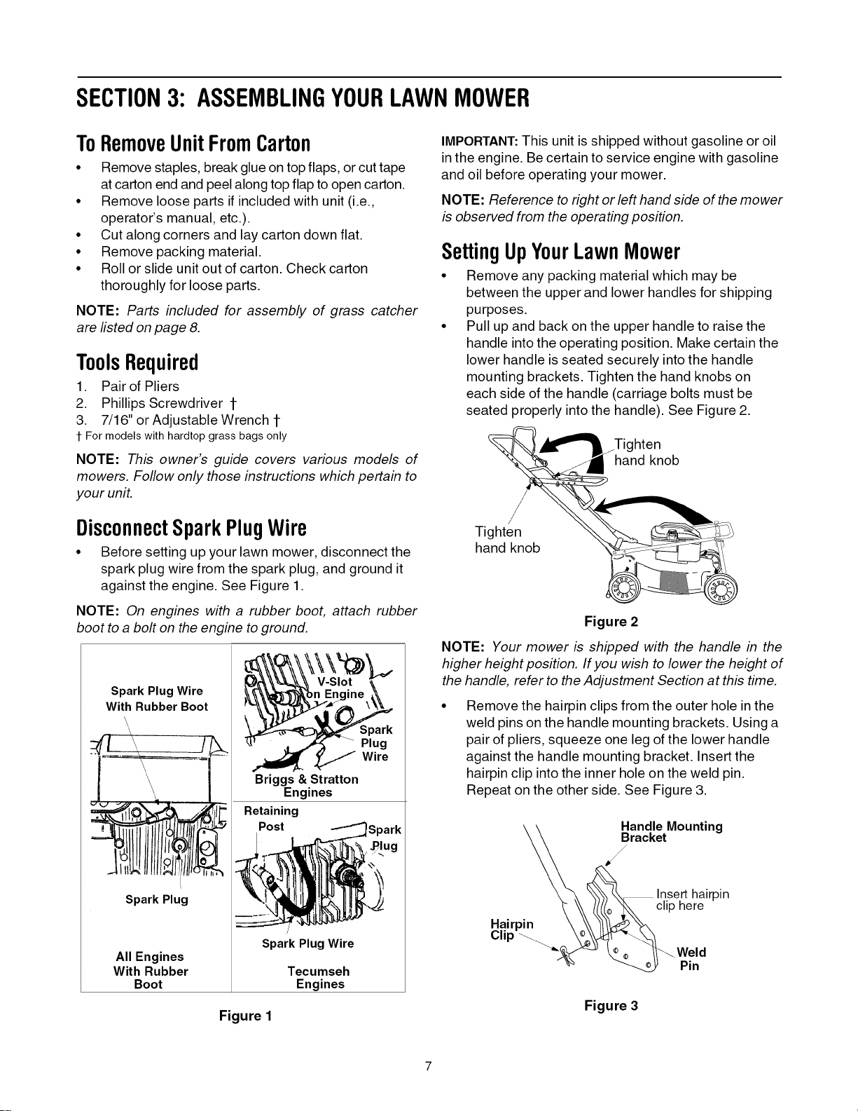
DisconnectSparkPlugWire
• Before setting up your lawn mower, disconnect the
spark plug wire from the spark plug, and ground it
against the engine. See Figure 1.
NOTE: On engines with a rubber boot, attach rubber
boot to a bolt on the engine to ground.
SparkPlugWire
WithRubberBoot
L....
Spark Plug
All Engines
With Rubber
Boot
Plug
Wire
Briggs & Stratton
Engines
Retaining
Post
/
SparkPlugWire
Tecumseh
Engines
Figure I
IMPORTANT:This unit is shipped without gasoline or oil
in the engine. Be certain to service engine with gasoline
and oil before operating your mower.
NOTE: Reference to right or left hand side of the mower
is observed from the operating position.
SettingUpYourLawnMower
• Remove any packing material which may be
between the upper and lower handles for shipping
purposes.
• Pull up and back on the upper handle to raise the
handle into the operating position. Make certain the
lower handle is seated securely into the handle
mounting brackets. Tighten the hand knobs on
each side of the handle (carriage bolts must be
seated properly into the handle). See Figure 2.
hten
hand knob
/
Tighten
hand knob
Figure 2
NOTE: Your mower is shipped with the handle in the
higher height position. If you wish to lower the height of
the handle, refer to the Adjustment Section at this time.
Remove the hairpin clips from the outer hole in the
weld pins on the handle mounting brackets. Using a
pair of pliers, squeeze one leg of the lower handle
against the handle mounting bracket. Insert the
hairpin clip into the inner hole on the weld pin.
Repeat on the other side. See Figure 3.
\ \ Handle Mounting
__ Bracket
\ _, \\_\\_lnsert hairpin
\\ _(_ _ clip here
Hairpin \ \\ _1/_
clip_ \o&_-_
_-_ _ _ _Weld
_ Pin
Figure 3
Loading ...
Loading ...
Loading ...