No: 341306 3/21
radiant
®
WNRL50 Smart Tru-Universal Dimmer with Netatmo; Incandescent, Halogen: 700W; LED: 450W; MLV: 500VA
Gradateur intelligent Tru-Universal radiant
®
WNRL50 avec Netatmo; Incandescente, halogène : 700 W; DEL : 450 W;
BTM : 500VA
Regulador inteligente Tru-Universal WNRL50 radiant
®
con Netatmo; incandescente, halógeno: 700W; LED: 450W;
MLV: 500VA
Installation Instructions • Directives D’installation • Directives D’installation
Catalog Number • Numéro(s) de Catalogue • Les Numéros de Catalogue: WNRL50
Country of Origin: Made in China • Pays de fabrication : Fabriqué en Chine • Pays de fabrication : Fabriqué en Chine
WNRL50
radiant
®
Smart
Dimmer
BEFORE YOU START
Review this guide in its entirety. Consult an electrician with any questions or
if you are unsure of your abilities.
Warning: Incorrect installation could result in death, serious injury, and/or
damage to your home or devices.
CAUTION: To reduce the risk of injury and/or overheating and damage to
other equipment:
• Do not install to control a receptacle or a motor-controlled appliance.
• For dry, indoor use only.
• Do not use to power medical equipment.
• Use ONLY with dimmable lighting loads.
• Do not use with loads exceeding the device
load rating.
• Connect the smart dimmer to a 120 VAC, 60 Hz power source ONLY.
• Always use copper wire to install the smart dimmer & follow all applicable
local & national electrical codes.
WHAT YOU NEED
Required:
• Phillips-head screwdriver
• Flat blade screwdriver
You May Also Need:
Voltage tester, pliers, wire cutter, wire stripper, electrical tape, flashlight,
wiring leads (included), and wire nuts (included).
INSTALLATION & SETUP
1. Turn Off Power To Device At Circuit Breaker
Flip existing light switch multiple times to confirm power is o.
NOTE: Ensure power is o to all devices in electrical box.
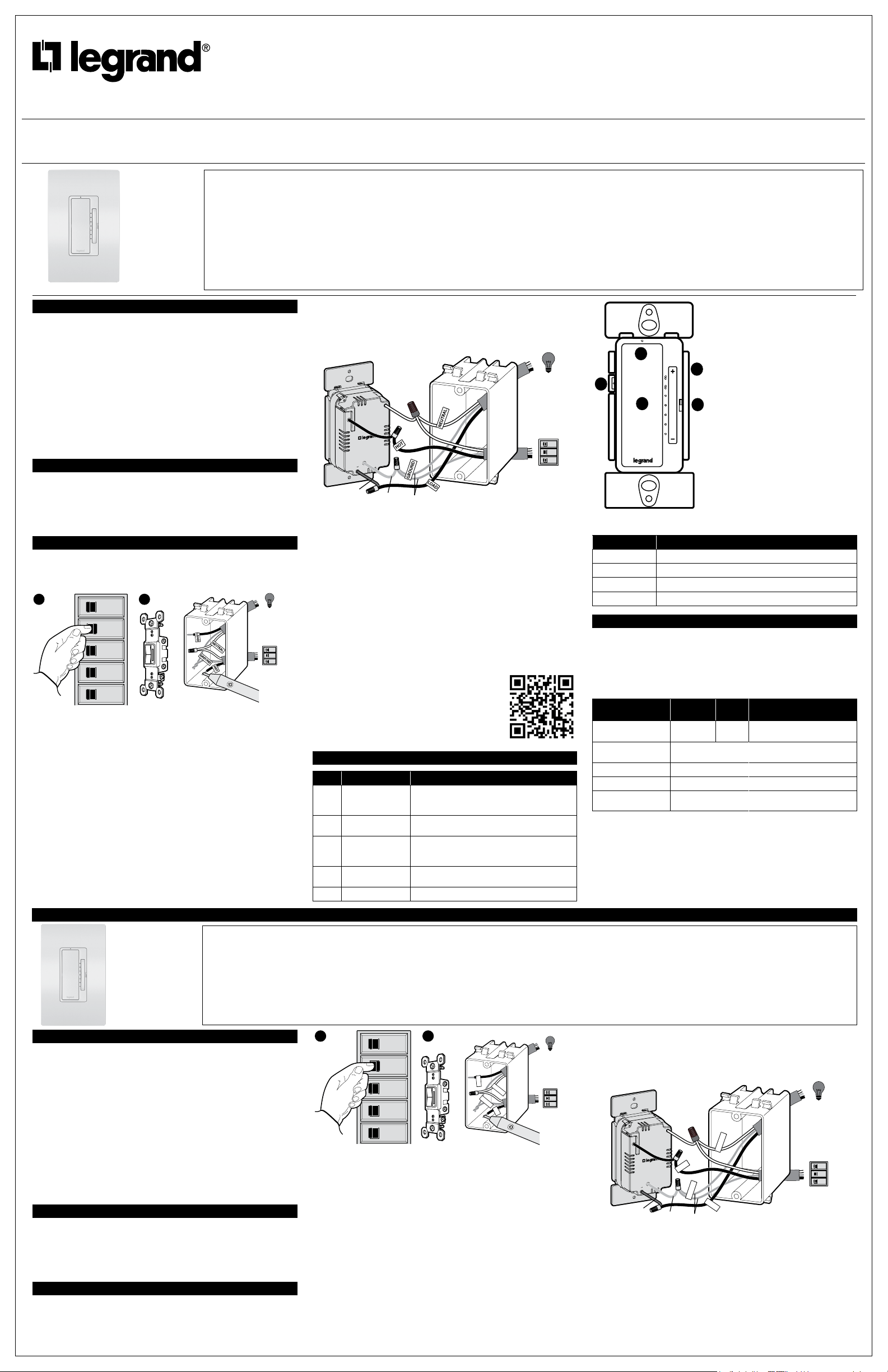
2. Remove Existing Device
Check for the following wires:
a. HOT or LINE: Receives power from the circuit box. Referred to as “hot”
for the purpose of this guide. Do not touch or let “hot” wire contact
other wires.
b. LOAD: Directs power to your light(s).
c. NEUTRAL: Creates a path to return current to the power source when
the device is o. Required for your dimmer installation.
d. GROUND: Provides a safe path for electricity in the event of a short
circuit.
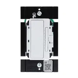
3. Wire Smart Dimmer
Use the wire nuts provided to secure the wires together.
a. Connect the WHITE neutral wire on the dimmer to the neutral wires in
the box, using the red wire nut.
b. Connect the LOAD wire on the dimmer to the load wire in the box.
c. Connect the HOT wire on the dimmer to the hot wire(s) in the box.
d. Connect the GREEN ground wire on the dimmer to the ground wire(s)
in the box.
4. Secure Smart Dimmer
a. Fold wires into electrical box, taking care not to pinch a wire.
b. Use included screws to secure smart dimmer to electrical box. Do not
fully tighten the screws.
5. Test The Smart Dimmer
NOTE: See getting to know your dimmer section for feature details.
Turn the power back on at the circuit breaker, press dimmer to turn light on/
o and use the dimmer paddle to adjust the level of your light(s).
This device is designed to work with a radiant
®
Smart Gateway with
Netatmo. Follow the instructions from your app to finish setting up your
dimmer.
TROUBLESHOOTING TIP: If the device is not powering check wiring to
determine if you have reversed the “HOT” and “LOAD” wiring.
6. Attach Wall Plate
a. Use the sub-plate screws (provided) to secure the sub-plate to the
smart dimmer.
b. Tighten device screws to secure smart dimmer to the electrical box.
c. Angle the UP end of the wall plate over the top edge of the sub-plate.
Push the screwless wall plate down and in until it “snaps” into place
over the sub-plate.
NOTE:
To remove the wall plate, place the tip of a flat blade screwdriver into
the slot under the wall plate and twist gently.
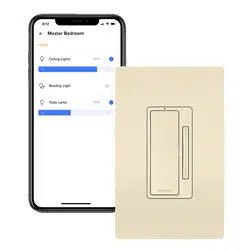
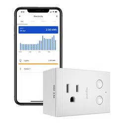
7. Set Up Your System
a. Download and launch the Legrand Home + Control app. The app is
available on the App Store or on Google Play.
b. Connect your smart device to your home
network by following the step
by step instructions in the app.
c. Use the app to control your smart device.
For the most recent instruction sheets or more
information on this product, please see this link or scan
the QR code:
https://www.legrand.us/p/wnrl50wh
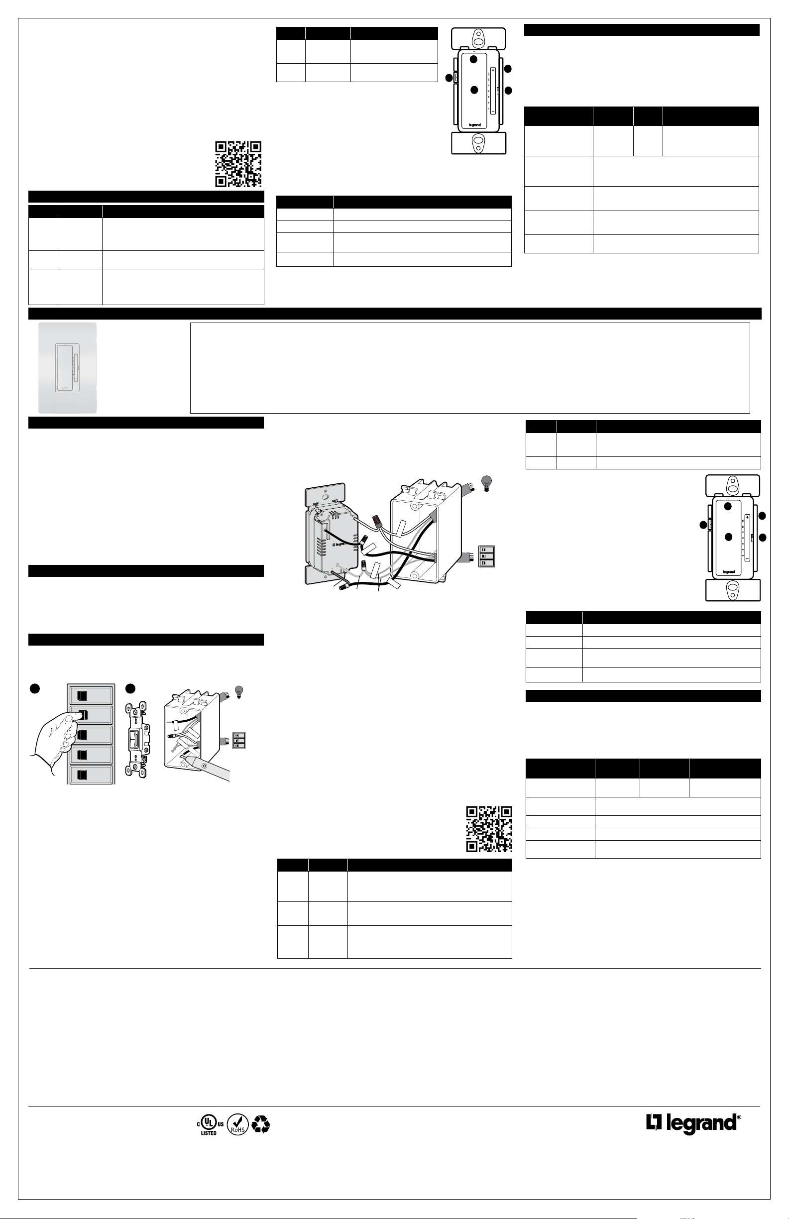
GETTING TO KNOW YOUR DIMMER
Item Name Description
1 Paddle Switch Press the top of the paddle to turn light on. Double-
tap to raise the dimming percentage to 100%.
Press the bottom of paddle to turn light o.
2 LED Locator Light Indicates the current state of device. Refer to “LED
Locator Light Explanations” for detail.
3 Dimmer Paddle /
LED Light Level
Controls and displays the dimming percentage.
Press (+/-) to adjust light in 2% increments. Hold
(+/-) to adjust light in 20% increments.
4 Air Gap Switch Completely turns o the dimmer. Use when changing
light bulbs.
5 EZ Button Used to enter setup mode.
Reset To Factory Default
Deleting a device from the app will reset
it to factory defaults.
To manually reset the device to factory
defaults press and hold the EZ button for
10 seconds until you see the LED blink
red then release. The LED will change to
solid red when the reset is complete.
LED Locator Light Explanations
State of Light Explanation
Solid White Lit when load is o.
Solid Red Factory reset, not in network.
Blinking Green Device is attempting to connect to the network.
Solid Green Device in network, temporarily open.
SPECIFICATIONS
De-rating of the dimmer is not required for reverse phase applications. For
forward phase applications in two-gang installations, de-rate incandescent,
halogen, or electronic low voltage (ELV) loads to 600 Watts; in three-gang
or greater installations, de-rate incandescent, halogen, or electronic low
voltage (ELV) loads to 600 Watts on the outer units and 500 Watts on the
center units.
RATING CHART
Load Rating
Dual-
Gang 3-Gang
Incandescent/Halogen/
ELV (FWD)
700W 600W/
600W
600W/500W/600W
Incandescent/Halogen/
ELV (REV)
450W
CFL/LED/EFL (FWD) 450W/3.8A
CFL/LED/EFL (REV) 250W/2.1A
Magnetic Low Voltage
(FWD)
500VA
Legrand reserves the right to change specifications without notice.
NOTE: The dimmer ships in forward phase mode to accommodate most
load types.
Refer to the app to enter reverse phase.
OFF
ON
OFF
ON
OFF
ON
OFF
ON
OFF
ON
OFF
ON
OFF
ON
OFF
ON
VOLTAGE
TESTER
Load
Supply
“Hot”
1 2
1-POLE
Gr
ound
WHITE
HO
T
OFF
ON
OFF
ON
OFF
ON
Load
Red
Green
Bare
Supply
“Hot”
2
1
3
4
5
AVANT DE COMMENCER
Passer l’ensemble de ce guide en revue. En cas de question ou
d’incertitude concernant ses capacités, consulter un électricien.
Mise en garde : Une installation inappropriée pourrait entraîner la mort,
des blessures graves et (ou) des dommages à votre domicile ou à vos
dispositifs.
MISE EN GARDE : Pour réduire le risque de blessures et (ou) de
surchaue et de dommage à d’autre matériel :
• Ne pas installer pour contrôler un réceptacle ou un appareil à moteur.
• Pour usage intérieur dans un endroit sec seulement.
• Ne pas utiliser pour alimenter du matériel médical.
• Utiliser UNIQUEMENT avec des charges d’éclairage à intensité réglable.
• Ne pas utiliser avec des charges dépassant la capacité de charge du
dispositif.
• Connecter le gradateur intelligent UNIQUEMENT dans une source
d’alimentation de 120 V c. a., 60 Hz.
• Toujours utiliser un fil de cuivre pour installer le gradateur intelligent et
respecter tous les codes de l’électricité locaux et nationaux applicables..
CE DONT VOUS AVEZ BESOIN
Obligatoire:
• Tournevis cruciforme
• Tournevis à tête plate
Autres éléments pouvant être requis:
Testeur de tension, pinces, pince coupe-fils, pince à dénuder, ruban isolant,
lampe de poche, fils de connexion (inclus) et connecteurs de fils (inclus).
INSTALLATION ET CONFIGURATION
1. Mettre le dispositif hors tension au niveau du disjoncteur
Appuyer plusieurs fois sur l’interrupteur actuel pour confirmer que le courant
est coupé.
REMARQUE : S’assurer que tous les dispositifs du boîtier électrique sont
hors tension.
2. Retirer le dispositif actuel
Vérifier les fils suivants:
a. FIL CHARGÉ ou FIL DE LIGNE : Reçoit le courant du boîtier de
circuits électriques. Appelé fil « chargé » aux fins du présent guide. Ne
pas toucher aux fils « chargés » ni les laisser entrer en contact avec
d’autres fils.
b. FIL DE CHARGE : Dirige le courant vers la ou les lumière(s).
c. FIL NEUTRE : Crée un chemin pour renvoyer le courant à la source
d’alimentation lorsque le dispositif est hors tension. Nécessaire pour
l’installation de votre gradateur.
d. Mise à la terre : Fournit un chemin sécuritaire à l’électricité en cas de
court-circuit.
3. Relier les ls du gradateur intelligent
Utiliser les connecteurs de fils fournis pour fixer les fils ensemble.
a. Connecter le fil neutre BLANC du gradateur aux fils neutres du boîtier
à l’aide du connecteur de fils rouge.
b. Connecter le fil DE CHARGE du gradateur au fil de charge du boîtier.
c. Connecter le fil CHARGÉ du gradateur au(x) fil(s) chargé(s) du boîtier.
d. Connecter le fil de terre VERT du gradateur au(x) fil(s) de terre du
boîtier.
4. Fixer le gradateur intelligent
a. Plier les fils dans le boîtier électrique en prenant soin de ne pas les pincer.
b. Utiliser les vis fournies pour fixer le gradateur intelligent au boîtier
électrique. Ne pas serrer complètement les vis.
5. Mettre le gradateur intelligent à l’essai
REMARQUE :
Consulter la section « apprendre à connaître votre
gradateur » pour plus de détails sur les caractéristiques.
Rétablir le courant au niveau du disjoncteur, appuyer sur le gradateur pour
allumer/éteindre la lumière et utiliser la palette du gradateur pour ajuster la
luminosité.
Ce dispositif est conçu pour fonctionner avec une passerelle intelligente
radiant
®
avec Netatmo. Suivre les directives de votre application pour
terminer la configuration du gradateur.
CONSEIL DE DÉPANNAGE : Si le courant n’est pas rétabli dans le
dispositif, vérifier le câblage pour s’assurer que les fils « CHARGÉS » et de
« CHARGE » n’ont pas été inversés.
INSTRUCTIONS EN FRANÇAIS
OFF
ON
OFF
ON
OFF
ON
OFF
ON
OFF
ON
OFF
ON
OFF
ON
OFF
ON
Charge
Fournir
“Chaud”
CHARGE
TERRE
NEUTRE
CHAUD
TESTEUR
DE TENSION
1 2
1-POLE
Gr
ound
WHITE
HO
T
OFF
ON
OFF
ON
OFF
ON
Charge
Rouge
Vert
Nu
Fournir
“Chaud”
CHARGE
TERRE
NEUTRE
CHAUD
REGULATORY INFORMATION
FCC NOTICE:
This device complies with Part 15 of the FCC rules.
Operation is subject to the following two conditions: (1) this device may
not cause harmful interference, and (2) this device must accept any
interference received, including interference that may cause undesirable
operation.
This equipment has been tested and found to comply with the limits for
a Class B digital device, pursuant to Part 15 of the FCC Rules. These
limits are designed to provide reasonable protection against harmful
interference in a residential installation. This equipment generates, uses,
and can radiate radio frequency energy and, if not installed and used in
accordance with the instructions, may cause harmful interference to radio
communications. However, there is no guarantee that interference will not
occur in a particular installation.
If this equipment does cause harmful interference to radio or television
reception, which can be determined by turning the equipment o and on,
the user is encouraged to try to correct the interference by one or more of
the following measures:
• Reorient or relocate the receiving antenna
• Increase the separation between the equipment and receiver
• Connect the equipment into an outlet on a circuit dierent from that to
which the receiver is connected
• Consult the dealer or an experienced radio/TV technician for help
This equipment complies with FCC radiation exposure limits set forth for
an uncontrolled environment. This equipment should be installed and
operated with a minimum distance of 10 mm between the transmitter’s
radiating structure(s) and the body of the user or nearby persons.
NOTE:
Any changes or modifications to this device that are not expressly
approved by the manufacturer will void the warranty and the user’s
authority to operate the equipment.
Contains FCC ID: 2AU5D982057
IC NOTICE: This device complies with Industry Canada license-exempt
RSS standards. Operation is subject to the following two conditions:
(1) this device may not cause interference; and (2) this device must
accept any interference, including interference that may cause undesired
operation of the device.
RF EXPOSURE STATEMENT: This equipment meets the SAR evaluation
limits given in RSS-102 Issue 5 requirements at the minimum separation
distance of 10 mm to the human body. Note: Any changes or modifi
cations to this device that are not expressly approved by the manufacturer,
will void the warranty and the user’s authority to operate the equipment.
IC: 25764-982057
HVIN: 982057
RENSEIGNEMENTS SUR LA RÉGLEMENTATION
AVIS DE LA FCC : Ce dispositif est conforme à la section 15 des règlements de la FCC. On peut s’en servir
sous réserve des deux conditions suivantes : 1) ce dispositif ne provoque pas d’interférences nuisibles; 2) ce
dispositif doit être en mesure d’accepter toute interférence reçue, y compris les interférences qui peuvent
causer un fonctionnement indésirable.
Ce matériel a été mis à l’essai et a été jugé conforme aux limites d’un dispositif numérique de classe B,
conformément à la section 15 des règlements de la FCC. Ces limites visent à offrir une protection
raisonnable contre les interférences nuisibles dans une installation résidentielle. Ce matériel génère, utilise
et peut émettre des radiofréquences et, s’il n’est pas installé ou utilisé conformément aux directives, peut
causer des interférences nuisibles aux communications radio. Toutefois, il n’existe aucune garantie contre la
possibilité d’interférences au sein d’un milieu précis.
Si ce matériel cause des interférences nuisibles à la réception des téléviseurs et des radios, ce qui peut être
déterminé en mettant à l’arrêt, puis en remettant en marche le matériel, l’utilisateur est encouragé à tenter de
corriger ces interférences par l’une ou plusieurs des mesures suivantes :
• réorienter ou déplacer l’antenne de réception;
• augmenter la distance entre le matériel et le récepteur;
• brancher le matériel dans une prise de courant appartenant à un circuit électrique différent de celui sur
lequel le récepteur est branché;
• demander de l’aide au fournisseur ou à un technicien spécialisé en radio/télévision.
Ce matériel est conforme aux limites d’exposition aux radiations de la FCC énoncées pour un environnement
non contrôlé. Ce matériel doit être installé et fonctionner à une distance minimale de 10 mm entre la structure
rayonnante du transmetteur et l’utilisateur ou les personnes se trouvant à proximité.
REMARQUE : Les changements ou les modications apportés à ce dispositif qui ne sont pas expressément
approuvés par le fabricant pourraient annuler la garantie ainsi que l’autorisation de l’utilisateur à se servir
du matériel.
Contient le n° d’ident. de la FCC : 2AU5D982057
0
AVIS DE L’IC : Ce dispositif est conforme aux normes CNR pour les appareils exempts de licence d’Industrie
Canada. On peut s’en servir sous réserve des deux conditions suivantes : 1) ce dispositif ne provoque pas
d’interférences; 2) ce dispositif doit être en mesure d’accepter toute interférence, y compris les interférences
qui peuvent causer un fonctionnement indésirable.
ÉNONCÉ RELATIF À L’EXPOSITION AUX RADIOFRÉQUENCES : Ce dispositif est conforme aux
limites d’évaluation du DAS énoncées dans les exigences CNR 102, 5e édition à la distance de séparation
minimale de 10 mm de l’humain. Remarque : Les changements ou les modications apportés à ce
dispositif qui ne sont pas expressément approuvés par le fabricant pourraient annuler la garantie ainsi que
l’autorisation de l’utilisateur à se servir du matériel.
IC: 25764-982057
HVIN: 982057
Gradateur
intelligent
Tru-Universal
radiant
®
WNRL50
6. Fixer la plaque murale
a. Utiliser les vis de la sous-plaque (fournies) pour fixer la sous-plaque au
gradateur intelligent.
b. Serrer les vis fournies avec le dispositif pour bien fixer le gradateur
intelligent au boîtier électrique.
c. Placer l’extrémité supérieure (UP) de la plaque murale en angle sur le
bord supérieur de la sous-plaque. Abaisser la plaque murale sans vis
jusqu’à ce qu’elle « s’enclenche » en place sur la sous-plaque.
REMARQUE : Pour retirer la plaque murale, placer la pointe d’un tournevis
à tête plate dans la fente située sous la plaque murale et la faire tourner
doucement.
7. Congurer votre système
a. Télécharger l’application Home + Control de Legrand et la lancer.
L’application est oerte sur l’App Store ou sur Google Play.
b. Connecter votre dispositif intelligent à votre réseau résidentiel en
suivant les directives détaillées fournies dans
l’application.
c. Utiliser l’application pour contrôler le dispositif
intelligent.
Pour les fiches d’instructions les plus récentes ou plus
d’informations sur ce produit, veuillez consulter ce lien ou
numériser le code QR : https://www.legrand.us/p/wnrl50wh
APPRENDRE À CONNAÎTRE VOTRE GRADATEUR
Article Nom Description
1 Interrupteur à
palette
Appuyer sur le haut de la palette pour allumer la lumière.
Appuyer deux fois pour faire passer le niveau de grada-
tion à 100 %.
Appuyer sur le bas de la palette pour éteindre la lumière.
2 Voyant DEL Indique l’état actuel du dispositif. Se reporter à la section
« Explications du voyant DEL » pour plus de détails.
3 Palette du
gradateur/
niveau de
luminosité
DEL
Contrôle et ache le pourcentage de gradation.
Appuyer sur (+/-) pour régler la luminosité par paliers de
2 %. Maintenir (+/-) pour régler la luminosité par paliers
de 20 %.
Article Nom Description
4 Interrupteur
d’entrefer
Éteint complètement le gra-
dateur. Utiliser pour changer
les ampoules.
5 Bouton EZ Utilisé pour entrer en mode
de configuration.
Réinitialisation pour rétablir les paramètres par
défaut établis en usine
La suppression d’un dispositif de l’application
entraînera une réinitialisation pour rétablir les
paramètres par défaut établis en usine.
Pour réinitialiser manuellement le dispositif afin de
rétablir les paramètres par défaut établis en usine,
appuyer sur le bouton EZ et le maintenir enfoncé
pendant 10 secondes jusqu’à ce que le voyant DEL
clignote, puis le relâcher. Le voyant DEL deviendra rouge fixe lorsque la
réinitialisation sera terminée.
Explications du voyant DEL
État du Voyant Explication
Blanc fixe Allumé lorsque la charge est éteinte.
Rouge fixe Réinitialisation des paramètres d’usine, pas dans le réseau.
Clignotant
Vert
Le dispositif tente de se connecter au réseau.
Vert fixe Dispositif dans le réseau, allumé temporairement.
CARACTÉRISTIQUES TECHNIQUES
Il n’est pas nécessaire de réduire les charges du gradateur pour
les applications en phase de retour. Pour les applications en phase
d’avancement dans les installations doubles, réduire les charges
incandescentes, halogènes ou électroniques à basse tension à 600 watts;
dans les installations triples ou supérieures, réduire les charges
incandescentes, halogènes ou électroniques basse tension à 600 Watts sur
les unités externes et à 500 Watts sur les unités centrales.
TABLEAU DES VALEURS NOMINALES
Charge
Valeur
nominale Double Triple
Incandescente/
halogène/électron-
ique à basse tension
(avancement)
700 W 600 W /
600 W
600 W / 500 W / 600 W
Incandescente/
halogène/électron-
ique à basse tension
(retour)
450 W
LFC/DEL/éclairage
fluorescent continu
(avancement)
450 W/3,8 A
LFC/DEL/éclairage
fluorescent continu
(retour)
250 W/2,1 A
Magnétique à basse
tension (avancement)
500 VA
Legrand se réserve le droit de modifier les caractéristiques techniques sans
préavis.
REMARQUE :
Le gradateur est livré en mode de phase d’avancement afin
de convenir à la plupart des types de charges.
Se reporter à l’application pour entrer en mode de phase de retour.
800.223.4185
1.877.BY.LEGRAND
www.legrand.us
www.legrand.ca
Questions? We’re here to help.
Phone: 1-877-833-3303 8:00 a.m. to 8:00 p.m. EST (M-F)
Email: [email protected]
Chat: https://www.legrand.us/radiant/smart-lighting.aspx
(Click on the chat icon to open a dialogue box)
Para consultar las patentes, visite www.legrand.us/patents
¿Tiene preguntas? Estamos aquí para ayudar.
Teléfono: 1-877-833-3303 de 8:00 a.m. a 8:00 p.m. EST (MF)
Correo electrónico: [email protected]
Chat: https://www.legrand.us/radiant/smart-lighting.aspx
(Haga clic en el icono de chat para abrir un cuadro de diálogo)
Pour voir les brevets qui couvrent le produit, consulter le site www.
legrand.us/patents
Vous avez des questions? Nous sommes là pour vous aider.
Téléphone : 1 877 833-3303 de 8 h à 20 h (HNE) (lundi au
vendredi)
Courriel : [email protected]
Clavardage : https://www.legrand.us/radiant/smart-lighting.aspx
(Cliquer sur l’icône de clavardage pour ouvrir une boîte de
dialogue)
No: 341306 2/21
© Copyright 2021 Legrand All Rights Reserved.
© Copyright 2021 Tous droits réservés Legrand.
© Copyright 2021 Legrand Todos los derechos reservados.
For covering patents, see www.legrand.us/patents
Pour couvrir les brevets, voir www.legrand.us/patents
Para cubrir las patentes, véase www.legrand.us/patents
LIMITED ONE YEAR WARRANTY
Legrand will remedy any defect in workmanship or material in Legrand products which may develop under
proper and normal use within ONE year from date of purchase by a consumer:
(1) by repair or replacement, or, at Legrand’s option, (2) by return of an amount equal to consumer’s
purchase price. Such remedy is IN LIEU OF ANY AND ALL EXPRESSED OR IMPLIED WARRANTIES
OF MERCHANTABILITY OR FITNESS FOR A PARTICULAR PURPOSE. Such remedy by Legrand
does not include or cover cost of labor for removal or reinstallation of the product. ALL OTHER FURTHER
ELEMENTS OF DAMAGE (INCIDENTAL OR CONSEQUENTIAL DAMAGES) FOR BREACH OF ANY
AND ALL EXPRESSED OR IMPLIED WARRANTIES INCLUDING WARRANTIES OF MERCHANTABILITY
OR FITNESS FOR A PARTICULAR PURPOSE ARE EXCLUDED HEREBY. (Some states do not allow
disclaimers or exclusion or limitation of incidental or consequential damages, so the above disclaimer and
limitation or exclusion may not apply to you.) ANY IMPLIED WARRANTIES INCLUDING WHERE REQUIRED
WARRANTIES OF MERCHANTABILITY OR FITNESS FOR A PARTICULAR PURPOSE SHALL BE LIMITED
TO THE ONE YEAR PERIOD SET FORTH ABOVE. (Some states do not allow limitations on how long an
implied warranty lasts, so the above limitation may not apply to you.)
To ensure safety, all repairs to Legrand products must be made by Legrand, or under its specific direction.
Procedure to obtain performance of any warranty obligation is as follows: (1) Contact Legrand, Syracuse,
New York 13221, for instructions concerning return or repair; (2) return the product to Legrand, postage paid,
with your name and address and a written description of the installation or use of the Legrand product, and
the observed defects or failure to operate, or other claimed basis for dissatisfaction. This warranty gives you
specific legal rights and you may also have other rights which vary from state to state.
GARANTIE LIMITÉE DE UNE ANNÉE
Legrand remédiera à tout défaut de fabrication ou matériel des produits Legrand qui peuvent survenir dans le
cadre d’une utilisation correcte et normale dans les une année de la date d’achat par un consommateur :
(1) par la réparation ou le remplacement, ou, au choix de Legrand, (2) le remboursement d’un montant
équivalent au prix d’achat du consommateur. Ledit recours REMPLACE TOUTES LES GARANTIES
EXPLICITES OU IMPLICITES DE QUALITÉ MARCHANDE OU D’APTITUDE À SATISFAIRE UNE
FONCTION PARTICULIÈRE. Ledit recours par Legrand n’inclut pas ni ne couvre le coût de la main-d’œuvre
pour le démontage ou la réinstallation du produit. TOUS AUTRES DOMMAGES (DIRECTS OU INDIRECTS)
EN CAS DE VIOLATION DE TOUTE GARANTIE EXPLICITE OU IMPLICITE Y COMPRIS LES GARANTIES
DE QUALITÉ MARCHANDE OU D’APTITUDE À SATISFAIRE UNE FONCTION PARTICULIÈRE SONT
EXCLUS PAR LES PRÉSENTES. (Certains États n’autorisent pas les dénégations de responsabilité,
les exclusions ou la limitation des dommages directs ou indirects; il se peut donc que la dénégation de
responsabilité et la limitation ou l’exclusion ci-dessus ne s’appliquent pas à vous.) TOUTE GARANTIE
IMPLICITE, Y COMPRIS LES GARANTIES DE QUALITÉ MARCHANDE OU DE CONVENANCE À UN
USAGE PARTICULIER DOIT ÊTRE LIMITÉE À LA PÉRIODE DE UNE ANNÉE ÉTABLIE CI-DESSUS.
(Certains États n’autorisent pas les limitations de durée d’une garantie implicite; les limitations ci-dessus
peuvent donc ne pas s’appliquer à vous.)
Pour assurer la sécurité, toutes les réparations des produits Legrand doivent être eectuées par Legrand ou
sous sa direction spécifique. Voici la marche à suivre pour obtenir l’exécution de toute obligation de garantie
: (1) Communiquer avec Legrand, Syracuse, New York, 13221, pour obtenir des directives concernant le
remboursement ou la réparation; (2) retourner le produit à Legrand, par un envoi en port payé, en indiquant
votre nom et votre adresse ainsi qu’une description écrite de l’installation ou de l’utilisation du produit Legrand,
et indiquer les défauts ou la défaillance de fonctionnement constatés ou tout autre motif d’insatisfaction. Cette
garantie vous donne des droits légaux particuliers, mais vous pouvez également avoir d’autres droits, selon
l’État où vous résidez.
GARANTÍA LIMITADA DE UNO AÑO
Durante un plazo de uno año a partir de la fecha de compra del consumidor, Legrand compensará cualquier
defecto de fabricación o material en los productos Legrand que se detecte a través de un uso adecuado y
normal:
(1) con reparación/reemplazo o, a opción de Legrand, (2) con devolución de una cantidad equivalente al
precio de compra del consumidor. Este recurso SUSTITUYE TODAS Y CADA UNA DE LAS GARANTÍAS
EXPRESAS O IMPLÍCITAS DE COMERCIABILIDAD O IDONEIDAD PARA UN PROPÓSITO EN
PARTICULAR. Este recurso de Legrand no incluye ni cubre el costo de la mano de obra requerida para el
retiro o reinstalación del producto. POR MEDIO DEL PRESENTE SE EXCLUYEN TODOS LOS DEMÁS
DAÑOS (EMERGENTES O INDIRECTOS) POR INCUMPLIMIENTO DE TODAS O CUALQUIERA DE
LAS GARANTÍAS EXPRESAS O IMPLÍCITAS, INCLUIDAS LAS GARANTÍAS DE COMERCIABILIDAD
O IDONEIDAD PARA UN PROPÓSITO EN PARTICULAR. (Algunos estados no permiten las exenciones
de responsabilidad o la exclusión o limitación de daños emergentes o indirectos; por lo tanto, la exención
de responsabilidad y la limitación o exclusión anteriores podrían no aplicarse en su caso). CUALQUIER
GARANTÍA IMPLÍCITA, INCLUYENDO LAS GARANTÍAS DE COMERCIABILIDAD O IDONEIDAD PARA
UN PROPÓSITO EN PARTICULAR QUE SEAN NECESARIAS, SE LIMITARÁ AL PERÍODO DE UNO
AÑO ESTABLECIDO ANTERIORMENTE. (Algunos estados no permiten limitar la duración de una garantía
implícita, por lo que la limitación anterior podría no aplicarse en su caso).
Para garantizar la seguridad, todas las reparaciones de los productos Legrand deben ser realizadas por
Legrand o bajo su dirección específica. El procedimiento para lograr el cumplimiento de cualquier obligación
de garantía es el siguiente: (1) Póngase en contacto con Legrand, Syracuse, Nueva York 13221, para obtener
instrucciones respecto a la devolución o reparación; (2) devuelva el producto a Legrand, con franqueo
pagado, junto con su nombre, dirección y una descripción escrita de la instalación o uso del producto
Legrand, así como los defectos o fallas de funcionamiento que se observaron o cualquier otra situación no
satisfactoria que desee declarar. Esta garantía le otorga derechos legales específicos y también puede tener
otros derechos según el estado.
ANTES DE COMENZAR
Revise esta guía completamente. Consulte a un electricista si tiene dudas o
no está seguro de sus capacidades.
Advertencia: Una instalación incorrecta puede provocar la muerte, lesiones
graves o daños en su hogar o dispositivos.
PRECAUCIÓN: Para reducir el riesgo de lesiones o sobrecalentamiento y
daños en otro equipo:
• No instale para controlar un receptáculo o un aparato controlado por motor.
• Solo para uso en áreas interiores secas.
• No lo use para alimentar equipos médicos.
• Úselo SOLO con cargas de iluminación regulables.
• No lo use con cargas que excedan la capacidad de carga del
dispositivo.
• Conecte el regulador inteligente a una fuente de alimentación de 120
VCA, 60 Hz SOLAMENTE.
• Utilice siempre cable de cobre para instalar el regulador inteligente y
siga todos los códigos eléctricos locales y nacionales aplicables..
QUÉ NECESITA
Se requiere:
• Destornillador Phillips
• Destornillador de punta plana
También podría necesitar:
Tester de voltaje, alicates, cortacables, pelacables, cinta aislante, linterna,
cables de conexión (incluidos) y tuercas de cable (incluidas).
INSTALACIÓN Y CONFIGURACIÓN
1. Apague la alimentación del dispositivo en el disyuntor
Mueva varias veces el interruptor de luz existente para confirmar que la
alimentación está apagada.
NOTA: asegúrese de que todos los dispositivos estén apagados en la caja
eléctrica.
2. Retire el dispositivo existente
Verifique los siguientes cables:
a. CON CARGA o LÍNEA: Recibe energía de la caja de circuitos. Se
denomina “vivo” en esta guía. No toque ni permita que el cable “vivo”
entre en contacto con otros cables.
b. CARGA: Dirige la energía a sus luces.
c. NEUTRO: Crea una ruta para devolver la corriente a la fuente de
alimentación cuando el dispositivo está apagado. Requerido para la
instalación del regulador.
d. Tierra: Proporciona una ruta segura para la electricidad en caso de
un cortocircuito.
3. Cablee el regulador inteligente
Use las tuercas de cable proporcionadas para asegurar los cables en
conjunto.
a. Conecte el cable neutro BLANCO en el regulador a los cables neutros
en la caja, utilizando la tuerca del cable rojo.
b. Conecte el cable de CARGA en el regulador al cable de carga en la
caja.
c Conecte el cable VIVO en el regulador a los cables vivos en la caja.
d. Conecte el cable de tierra VERDE del regulador a los cables de tierra
en la caja
4. Asegure el regulador inteligente
a. Doble los cables en la caja eléctrica, teniendo cuidado de no pellizcar
ninguno.
b. Use los tornillos incluidos para asegurar el regulador inteligente a la
caja eléctrica. No apriete completamente los tornillos.
5. Pruebe el regulador inteligente
NOTA: Consulte la sección Conozca su regulador para obtener detalles
sobre las funciones.
Vuelva a encender el disyuntor, presione el regulador para encender/apagar
la luz y use el regulador de paleta para ajustar el nivel de las luces.
Este dispositivo está diseñado para funcionar con una Puerta de enlace
inteligente radiant
®
con Netatmo. Siga las instrucciones de su aplicación
para terminar de configurar su regulador.
CONSEJO PARA SOLUCIONAR PROBLEMAS: Si el dispositivo no se
está cargando, verifique el cableado para determinar si ha invertido el
cableado “VIVO” y “CARGA”.
6. Instale la placa de pared
a. Use los tornillos de la subplaca (provistos) para asegurar la subplaca
al regulador inteligente.
b. Apriete los tornillos del dispositivo para fijar el regulador inteligente a
la caja eléctrica.
c. Incline el extremo ARRIBA de la placa de pared sobre el borde
superior de la subplaca. Empuje la placa de pared sin tornillos hacia
abajo y adentro hasta que encaje en su lugar sobre la subplaca.
NOTA: Para quitar la placa de pared, coloque la punta de un destornillador
de punta plana en la ranura debajo de la placa de pared y gire suavemente.
7. Congure el sistema
a. Descargue e inicie la aplicación Legrand Home + Control. La
aplicación está disponible en la App Store o en Google Play.
b. Conecte su interruptor inteligente a su red doméstica siguiendo las
instrucciones paso a paso en la aplicación.
c Use la aplicación para controlar su dispositivo
inteligente. CON
Para las hojas de instrucciones más recientes o más
información sobre este producto, consulte este enlace o
escanee el código QR:.
https://www.legrand.us/p/wnrl50whOZCA
Artículo Nombre Descripción
1 Interruptor
de paleta
Presione la parte superior de la paleta para encender
la luz. Toque dos veces para aumentar el porcentaje de
regulación al 100% Presione la parte inferior de la paleta
para apagar la luz.
2 Luz de
localización
LED
Indica el estado actual del dispositivo. Para obtener más
detalles, consulte “Explicaciones de la luz de localización
LED”.
3 Paleta de
regulación /
Nivel de luz
LED
Controla y muestra el porcentaje de regulación.
Presione (+/-) para ajustar la luz en incrementos del 2%.
Mantenga presionado (+/-) para ajustar la luz en incremen-
tos del 20%.
Artículo Nombre Descripción
4 Interruptor
de espacio
de aire
Apaga completamente el regulador. Úselo cuando cambie
las bombillas.
5 Botón EZ
Se usa para ingresar al modo de configuración.
Restablecer a la conguración de fábrica
Eliminar un dispositivo de la aplicación lo restablecerá
a la configuración de fábrica.
Para restablecer manualmente el dispositivo a la
configuración predeterminada de fábrica, mantenga
presionado el botón EZ durante 10 segundos hasta
que vea que el LED parpadea en rojo y luego suelte.
El LED cambiará a rojo fijo cuando se complete el
restablecimiento.
Explicaciones de la luz de localización LED
Estado de la luz Explicación
Blanco fijo Encendido cuando la carga está apagada.
Rojo fijo Restablecimiento de fábrica, no en red.
Parpadea en
verde
El dispositivo está intentando conectarse con la red.
Verde fijo Dispositivo en red, abierto temporalmente.
ESPECIFICACIONES
No es necesario reducir la intensidad del regulador para aplicaciones de
fase inversa. Para aplicaciones de fase directa en instalaciones dobles,
reduzca las cargas incandescentes, halógenas o electrónicas de bajo
voltaje (ELV) a 600 watts; en instalaciones triples o superiores, reduzca las
cargas incandescentes, halógenas o electrónicas de bajo voltaje (ELV) a
600 watts en las unidades externas y a 500 watts en las unidades centrales
TABLA DE CALIFICACIÓN
Carga Clasicación
Conguración
Doble Conguración Triple
Incandescente/
Halógena/ELV (DIR)
700W 600W / 600W 600W / 500W / 600W
Incandescente /
Halógena / ELV (INV)
450W
CFL / LED / EFL (DIR) 450W / 3.8A
CFL / LED / EFL (INV) 250W / 2.1A
Bajo voltaje magnético
(DIR)
500VA
Legrand se reserva el derecho de cambiar las especificaciones sin previo aviso.
NOTA: el regulador se envía en modo de fase directa para acomodar la mayoría
de los tipos de carga.
Consulte la aplicación para ingresar a la fase inversa.
INSTRUCCIONES EN ESPAÑOL
2
1
3
4
5
OFF
ON
OFF
ON
OFF
ON
OFF
ON
OFF
ON
OFF
ON
OFF
ON
OFF
ON
Carga
Suministro
“Caliente”
CARGA
TIERRA
NEUTRAL
CALIENTE
PROBADOR
DE VOLTAJE
1 2
1-POLE
Gr
ound
WHITE
HO
T
OFF
ON
OFF
ON
OFF
ON
Carga
Rojo
Verde
Desnudo
Suministro
“Caliente”
CARGA
TIERRA
NEUTRAL
CALIENTE
2
1
3
4
5
INFORMACIÓN NORMATIVA
AVISO DE LA FCC: Este dispositivo cumple con la Parte 15 de las reglas de la FCC. La operación está
sujeta a las siguientes dos condiciones: (1) este dispositivo no debe provocar interferencia perjudicial,
y (2) este dispositivo debe aceptar cualquier interferencia recibida, incluso interferencia que pueda
provocar una operación no deseada.
Este equipo ha sido probado y cumple con los límites para un dispositivo digital Clase B, conforme con
la Parte 15 de las Reglas de la FCC. Estos límites están diseñados para proporcionar una protección
razonable contra interferencias perjudiciales en una instalación residencial. Este equipo genera, utiliza
y puede irradiar energía de radiofrecuencia y, si no se instala y utiliza de acuerdo con las instrucciones,
puede causar interferencias perjudiciales en las comunicaciones de radio. Sin embargo, no existe
garantía de que no se produzcan interferencias en una instalación especíca.
Si este equipo causa interferencias perjudiciales en la recepción de radio o televisión, lo que puede
determinarse apagando y encendiendo el equipo, se recomienda al usuario que intente corregir la
interferencia mediante una o más de las siguientes medidas:
• Reoriente o reubique la antena receptora
• Aumente la separación entre el equipo y el receptor
• Conecte el equipo a un tomacorriente en un circuito diferente al que alberga la conexión
del receptor
• Consulte al distribuidor o a un técnico experimentado de radio/TV para obtener ayuda.
Este equipo cumple con los límites de exposición a la radiación de la FCC establecidos para un entorno
no controlado. Este equipo debe instalarse y operarse con una distancia mínima de 10 mm entre la(s)
estructura(s) radiante(s) del transmisor y el cuerpo del usuario o de personas cercanas.
NOTA: cualquier cambio o modicación a este dispositivo que no esté expresamente aprobado por el
fabricante anulará la garantía y la autoridad del usuario para operar el equipo.
Contiene FCC ID: 2AU5D982057
AVISO de IC: Este dispositivo cumple con los estándares RSS exentos de licencia de Industry Canada.
La operación está sujeta a las siguientes dos condiciones: (1) este dispositivo no debe provocar
interferencia perjudicial, y (2) este dispositivo debe aceptar cualquier interferencia recibida, incluso
interferencia que pueda provocar una operación no deseada del dispositivo.
DECLARACIÓN DE EXPOSICIÓN A RF: Este equipo cumple con los límites de evaluación SAR
establecidos en los requisitos de RSS-102 Tema 5 a una distancia mínima de separación de 10 mm al
cuerpo humano. Nota: Cualquier cambio o modicación en este dispositivo que no estén expresamente
aprobados por el fabricante anularán la garantía y la autoridad del usuario para operar el equipo.
IC: 25764-982057
HVIN: 982057
Regulador
inteligente
Tru-Universal
WNRL50
radiant
®