Operator's Manual
I:Rl FI'SlVl N
208cc Engine
Rear Tine Tiller
Model No. 247.299301
CAUTION: Before using
this product, read this
manual and follow aJl
safety rules and operating
instructions.
* SAFETY
* ASSEMBLY
* OPERATION
* MAINTENANCE
* PARTS LIST
* ESPANOL
Sears Brands Management Corporation, Hoffman Estates, IL 60179, U.S.A.
Visit our web site: www.craftsman.com
FORMNO.769-08054A
5/29/2012
WarrantyStatement..................................Pac
Safetyinstructions....................................Pac
Assembly..................................................Pac
Operation..................................................Pac
ServiceandMaintenance.........................Pac
Off-SeasonStorage..................................Pac
TroubleShooting.......................................Pac
e2
es3-6
es7-10
es11-16
es17-22
e23
e24
PartsList...................................................Page26-40
Labels.......................................................Page41
RepairProtectionAgreement...................Page44
Espa_ol.....................................................Page45
ServiceNumbers......................................BackCover
CRAFTSMAN TWO YEAR FULL WARRANTY
FORTWOYEARSfromthe dateof purchase,this productis warrantedagainstanydefectsin materialor workmanship,A defectiveproductwill
receivefree repairor replacementif repairis unavailable,
For warranty coverage details to obtain free repair or replacement,visit the web site: www.craftsman.com
This warranty covers ONLYdefects in material andworkmanship. Warranty coverage does NOT include:
• Expendableitemsthat can wearoutfromnormalusewithinthewarrantyperiod,suchas the blades,tines, orbelts.
• Productdamageresultingfromuserattemptsat productmodificationor repairor caused by productaccessories.
• Repairsnecessarybecauseof accidentor failureto operateor maintainthe productaccordingto all suppliedinstructions.
• Preventivemaintenance,or repairsnecessarydueto improperfuel mixture,contaminatedor stalefuel.
Thiswarrantyis void if this productis everusedwhile providingcommercialservicesor if rentedto anotherperson.
Thiswarrantygivesyou specificlegal rights,and you mayalso haveotherrights whichvary from stateto state.
Sears Brands Management Corporation, Hoffman Estates, IL 60179
EngineSeries: 208cc
EngineOilType: 10w30
EngineOilCapacity: 20ounces
Fuel: UnleadedGasoline
SparkPlug: F6RTC
SparkPlugGap: .030"
ModelNumber.................................................................
Serial Number .................................................................
Dateof Purchase.............................................................
Recordthe modelnumber,serialnumber
anddateof purchaseabove
© Sears Brands,LLC 2
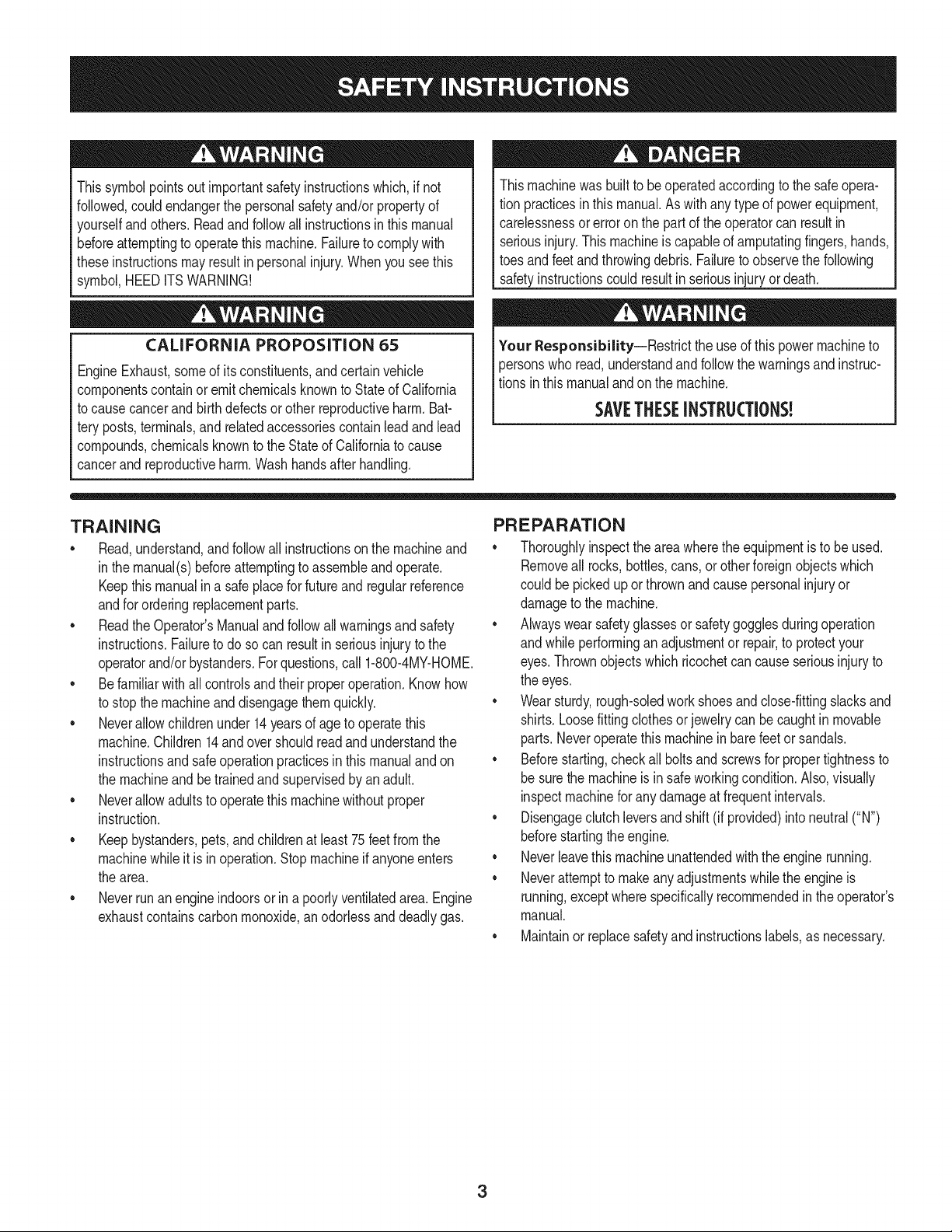
Thissymbolpointsout importantsafetyinstructionswhich,if not
followed,couldendangerthe personalsafetyand/orpropertyof
yourselfandothers. Readand followall instructionsin thismanual
beforeattemptingto operatethis machine.Failureto complywith
theseinstructionsmay resultin personalinjury.Whenyou seethis
symbol,HEEDITSWARNING!
CALIFORNIA PROPOSITION 65
EngineExhaust,someof itsconstituents,andcertainvehicle
componentscontainoremit chemicalsknownto Stateof California
to cause cancerand birthdefectsorother reproductiveharm. Bat-
tery posts,terminals,andrelatedaccessoriescontainleadand lead
compounds,chemicalsknownto the Stateof Californiato cause
cancerandreproductiveharm.Washhandsafterhandling.
Thismachinewasbuilt to be operatedaccordingto the safeopera-
tion practicesin thismanual.As withany type of powerequipment,
carelessnessor error on the part of the operatorcan resultin
seriousinjury.Thismachineis capableof amputatingfingers,hands,
toesandfeetandthrowingdebris.Failureto observethe following
safetyinstructionscouldresultin seriousinjuryordeath.
Your Responsibility--Restrictthe use of this powermachineto
personswho read,understandandfollowthewarningsand instruc-
tionsin thismanualandon the machine.
SAVETHESEINSTRUCTIONS!
TRAINING
• Read,understand,andfollowall instructionson the machineand
in themanual(s)beforeattemptingto assembleandoperate.
Keepthis manualina safeplacefor futureand regularreference
andfor orderingreplacementparts.
• Readthe Operator'sManualand followallwarningsand safety
instructions.Failureto doso can resultin seriousinjuryto the
operatorand/or bystanders.Forquestions,call 1-800-4MY-HOME.
• Be familiarwith all controlsand their properoperation.Knowhow
to stop the machineanddisengagethemquickly.
• Neverallowchildrenunder14yearsof age to operatethis
machine.Children14andover shouldreadandunderstandthe
instructionsand safe operationpracticesin thismanualandon
the machineandbe trainedandsupervisedby an adult.
• Neverallowadultsto operatethis machinewithoutproper
instruction.
• Keepbystanders,pets,and childrenat least 75 feetfrom the
machinewhile it is in operation.Stopmachineif anyoneenters
the area.
• Neverrun an engine indoorsor in a poorlyventilatedarea.Engine
exhaustcontainscarbonmonoxide,an odorlessand deadlygas.
PREPARATION
• Thoroughlyinspecttheareawherethe equipmentis to be used.
Removeall rocks,bottles,cans,or otherforeignobjectswhich
could be pickedup or thrownand cause personalinjuryor
damageto the machine.
• Alwayswear safetyglassesor safetygogglesduringoperation
andwhile performingan adjustmentor repair,to protectyour
eyes.Thrownobjectswhich ricochetcan causeseriousinjuryto
the eyes.
• Wearsturdy,rough-soledwork shoesand close-fittingslacksand
shirts.Loosefittingclothesor jewelrycan becaughtin movable
parts.Neveroperatethis machinein bare feet or sandals.
• Beforestarting,checkallboltsandscrewsfor propertightnessto
besurethe machineis in safe workingcondition.Also,visually
inspectmachinefor any damageat frequentintervals.
• Disengageclutchleversandshift (if provided)into neutral("N")
beforestartingtheengine.
• Neverleavethis machineunattendedwiththe engine running.
• Neverattemptto make anyadjustmentswhilethe engineis
running,exceptwherespecificallyrecommendedin the operator's
manual.
• Maintainor replacesafetyandinstructionslabels,as necessary.
3

Safe Handling of Gasoline:
Toavoidpersonalinjuryor propertydamageuseextremecare in
handlinggasoline.Gasolineis extremelyflammableandthe vaporsare
explosive.Seriouspersonalinjurycan occurwhengasolineis spilled
onyourselfor yourclotheswhichcan ignite.Washyour skinand
changeclothesimmediately.
• Use onlyan approvedgasolinecontainer.
• Neverfill containersinsidea vehicleor ona truckor trailerbed
witha plasticliner.Alwaysplacecontainersonthe groundaway
fromyour vehiclebeforefilling.
• Whenpractical,removegas-poweredequipmentfromthe truck
ortrailerand refueliton the ground.If this is notpossible,then
refuelsuchequipmenton a trailerwith a portablecontainer,rather
thanfrom a gasolinedispensernozzle.
• Keepthe nozzleincontactwiththe rimof the fuel tank or
containeropeningat alltimes untilfuelingis complete.Do not use
a nozzlelock-opendevice.
• Extinguishall cigarettes,cigars,pipesandother sourcesof
ignition.
• Neverfuel machineindoors.
• Neverremovegas capor addfuel whilethe engineishot or run-
ning.Allowengineto cool at leasttwo minutesbeforerefueling.
• Neveroverfill fueltank. Fill tankto nomorethan1/2inchbelow
bottomof filler neckto allowspacefor fuel expansion.
• Replacegasolinecapandtightensecurely.
• If gasolineisspilled,wipe itoff theengineandequipment.Move
unitto anotherarea.Wait5 minutesbeforestartingthe engine.
• To reducefire hazards,keepmachinefreeof grass, leaves,or
otherdebrisbuild-up.Cleanupoil or fuel spillageand removeany
fuel soakeddebris.
• Neverstorethe machineorfuel containerinsidewherethereis an
openflame,spark or pilotlightas on awaterheater,spaceheater,
furnace,clothesdryer or othergas appliances.
OPERATION
• Do not puthandsor feet near rotatingparts.Contactwith the
rotatingpartscan amputatehandsand feet.
• Do notoperatemachinewhileunderthe influenceof alcoholor
drugs.
• Neveroperatethis machinewithoutgood visibilityor light.Always
be sureof yourfootingand keepa firmholdonthe handles.
• Keepbystandersawayfromthe machinewhileit isinoperation.
Stopthe machineif anyoneentersthe area.
• Be carefulwhentilling in hard ground.Thetines maycatchin the
groundandpropelthe tillerforward.If this occurs,let goof the
handlebarsand do not restrainthe machine.
• Exerciseextremecautionwhenoperatingonor crossinggravel
surfaces.Stayalert for hiddenhazardsortraffic. Do notcarry
passengers.
• Neveroperatethe machineat hightransportspeedson hard or
slipperysurfaces.
• Exercisecautionto avoidslippingor falling.
• Lookdownand behindandusecare whenin reverseor pulling
machinetowardsyou.
• Start the engineaccordingto the instructionsfoundinthis manual
and keepfeetwell awayfromthe tinesat all times.
• After strikingaforeignobjector ifyour machineshouldstart mak-
ingan unusualnoiseor vibration,immediatelyshutthe engineoff.
Disconnectthe sparkplugwire,grounditagainstthe engineand
performthe followingsteps:
a. Inspectfor damage.
b. Repairor replaceanydamagedparts.
c. Checkfor anyloose partsandtightento assurecontinued
safeoperation.
• Disengageall clutchlevers(if fitted)and stopenginebeforeyou
leavethe operatingposition(behindthe handles).Waituntil
the tines cometo a completestopbeforeuncloggingthe tines,
makingany adjustments,or inspections.
• Neverrun an engineindoorsorina poorlyventilatedarea.Engine
exhaustcontainscarbonmonoxide,an odorlessand deadlygas.
• Mufflerand enginebecomehot andcancause a burn.Do not
touch.
• Usecautionwhentillingnear fences,buildingsand underground
utilities.Rotatingtines can causepropertydamageor personal
injury.
• Donot overloadmachinecapacityby attemptingto till soil too
deepat too fastof a rate.
• If the machineshouldstart makingan unusualnoiseor vibration,
stopthe engine,disconnectthe spark plugwire andgroundit
againstthe engine.Inspectthoroughlyfor damage.Repairany
damagebeforestartingandoperating.
• Keepall shields,guards,and safetydevicesin placeandoperat-
ing properly.
• Neverpick uporcarrymachinewhilethe engineis running.
• Useonly attachmentsandaccessoriesapprovedby the manu-
factureras listedin the PartsList pagesof this operator'smanual.
Failureto do so can resultin personalinjury.
• If situationsoccurwhichare notcoveredinthis manual,use care
andgoodjudgement.ContactCustomerSupportat 1-800-4MY-
HOMEfor assistanceandthe nameof thenearestservicedealer
MAINTENANCE & STORAGE
• Keepthe machine,attachmentsandaccessoriesin safeworking
order.
• Allowthe machineto coolat leastfiveminutesbeforestoring.
Nevertamperwithsafetydevices.Checktheirproperoperation
regularly.
• Checkboltsandscrewsfor propertightnessat frequentintervals
to keepthe machineinsafeworkingcondition.Also,visually
inspectmachineforany damage.
• Beforecleaning,repairing,or inspecting,stop the engineand
makecertainthetines and all movingpartshavestopped.
Disconnectthe sparkplug wireandgrounditagainstthe engineto
preventunintendedstarting.
4
• Do notchangethe enginegovernorsettingsor over-speedthe
engine.Thegovernorcontrolsthemaximumsafeoperatingspeed
of engine.
Maintainor replacesafetyand instructionlabels,as necessary.
Followthis manualfor safe loading,unloading,transporting,and
storageof thismachine.
Alwaysreferto theoperator'smanualfor importantdetailsif the
machineis to bestoredforan extendedperiod.
If thefuel tankhasto be drained,do this outdoors.
Observeproperdisposallawsandregulationsfor gas,oil, etc.to
protectthe environment.
Accordingto the ConsumerProductsSafetyCommission(CPSC)
andthe U.S.EnvironmentalProtectionAgency(EPA),thisproduct
hasan AverageUsefulLifeof seven(7)years,or 130 hoursof
operation.At the endof theAverageUsefulLifehavethe machine
inspectedannuallyby anauthorizedservicedealerto ensurethat
allmechanicaland safetysystemsareworkingproperlyandnot
wornexcessively.Failureto do so can resultinaccidents,injuries
ordeath.
DO NOT MODIFY ENGINE
Toavoidseriousinjuryor death, do not modifyenginein anyway.
Tamperingwiththe governorsettingcan leadto a runawayengineand
causeit to operateat unsafespeeds.Nevertamperwithfactorysetting
of enginegovernor.
NOTICE REGARDING EMISSIONS
Engineswhich are certifiedtocomplywithCaliforniaandfederal
EPAemissionregulationsfor SORE(SmallOff RoadEquipment)are
certifiedto operateon regularunleadedgasoline,and mayinclude
the followingemissioncontrolsystems:EngineModification(EM),
OxidizingCatalyst(CO), SecondaryAirInjection(SAI)and ThreeWay
Catalyst(TWO)if so equipped.
SPARK ARRESTOR
Thismachineis equippedwith an internalcombustionengineand
shouldnotbe usedon or near anyunimprovedforest-covered,
brushcoveredor grass-coveredlandunlessthe engine'sexhaust
systemis equippedwith a sparkarrestormeetingapplicablelocal or
statelaws (if any)
Ifa sparkarrestoris used, it shouldbe maintainedin effectiveworking
orderby theoperator.Inthe Stateof Californiathe aboveis required
bylaw (Section4442of the CaliforniaPublicResourcesCode).Other
statesmayhavesimilarlaws. Federallawsapplyon federallands.
A sparkarrestorfor the muffleris availablethroughyournearestSears
PartsandRepairServiceCenter.
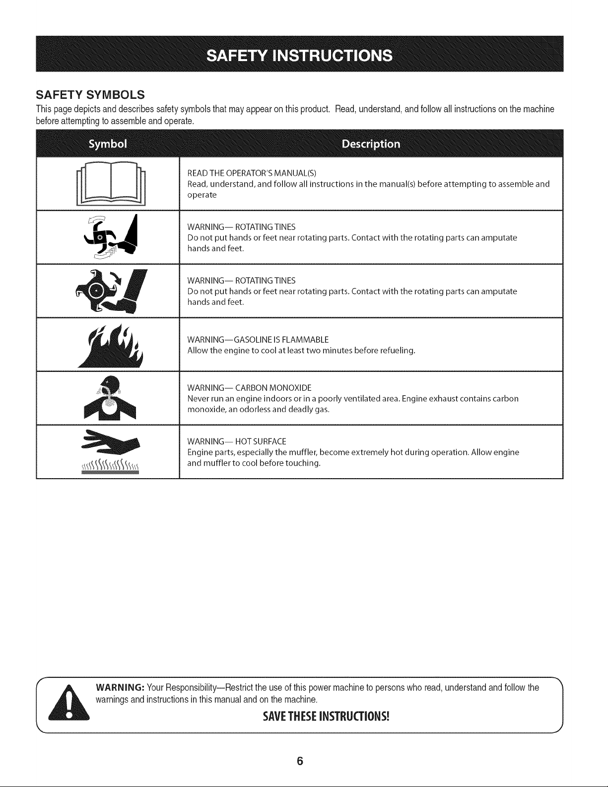
SAFETY SYMBOLS
Thispagedepictsand describessafetysymbolsthatmayappearonthis product. Read,understand,and followall instructionson the machine
beforeattemptingto assembleandoperate.
i
i
READ THE OPERATOR'S MANUAL(S)
Read, understand, and follow all instructions in the manual(s) before attempting to assemble and
operate
WARNING-- ROTATING TINES
Do not put hands or feet near rotating parts. Contact with the rotating parts can amputate
hands and feet.
WARNING-- ROTATING TINES
Do not put hands or feet near rotating parts. Contact with the rotating parts can amputate
hands and feet.
WARNING--GASOLINE IS FLAMMABLE
Allow the engine to cool at least two minutes before refueling.
WARNING-- CARBON MONOXIDE
Never run an engine indoors or in a poorly ventilated area. Engine exhaust contains carbon
monoxide, an odorless and deadly gas.
WARNING-- HOT SURFACE
Engine parts, especially the muffler, become extremely hot during operation. Allow engine
and muffler to cool before touching.
WARNING: YourResponsibility--Restrictthe useof this powermachineto personswho read,understandandfollowthe
warningsand instructionsinthis manualandonthe machine.
SAVETHESEINSTRUCTIONS!
6
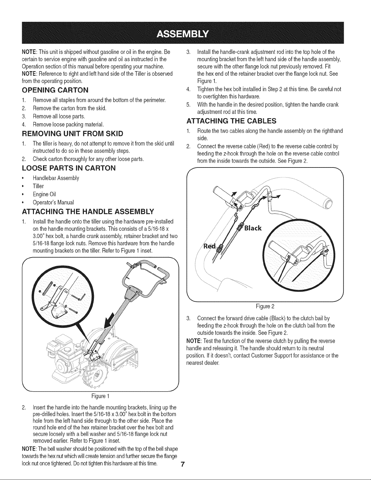
NOTE:This unitis shippedwithoutgasolineor oil inthe engine.Be
certainto serviceenginewithgasolineandoil as instructedin the
Operationsectionof this manualbeforeoperatingyourmachine.
NOTE:Referenceto rightand lefthandsideof the Tilleris observed
fromthe operatingposition.
OPENING CARTON
1. Removeall staplesfromaroundthe bottomof the perimeter.
2. Removethe carton fromthe skid.
3. Removeall looseparts.
4. Removeloosepackingmaterial.
REMOVING UNIT FROM SKID
1. Thetiller is heavy,do notattemptto removeit from the skiduntil
instructedto do so in these assemblysteps.
2. Checkcarton thoroughlyfor anyotherlooseparts.
LOOSE PARTS IN CARTON
• HandlebarAssembly
• Tiller
• EngineOil
• Operator'sManual
ATTACHING THE HANDLE ASSEMBLY
1. Installthe handleontothetiller usingthe hardwarepre-installed
onthe handlemountingbrackets.Thisconsistsof a 5/16-18x
3.00"hex bolt,a handlecrankassembly,retainerbracketandtwo
5/16-18flangelocknuts. Removethishardwarefromthe handle
mountingbracketson the tiller.Referto Figure1 inset.
f -_,
3. Installthe handle-crankadjustmentrod intothe top holeof the
mountingbracketfromthe left handsideof the handleassembly,
securewiththe otherflangelock nut previouslyremoved.Fit
the hexend of the retainerbracketoverthe flangelocknut.See
Figure1.
4. Tightenthe hexbolt installedin Step2 atthis time.Be carefulnot
to overtightenthis hardware.
5. With the handlein the desiredposition,tightenthe handlecrank
adjustmentrodat thistime.
ATTACHING THE CABLES
1. Routethe two cables alongthe handleassemblyon the righthand
side.
2. Connectthe reversecable(Red)to the reversecablecontrolby
feedingthez-hookthroughthe holeon the reversecablecontrol
fromthe insidetowardstheoutside.SeeFigure2.
f ---
/
Figure2
3. Connecttheforwarddrivecable(Black) to the clutchbailby
feedingthez-hookthroughthe holeon the clutchbail fromthe
outsidetowardsthe inside. See Figure2.
NOTE:Testthefunctionof the reverseclutchby pullingthe reverse
handleand releasingit.The handleshouldreturnto its neutral
position.If it doesn't,contactCustomerSupportforassistanceorthe
nearestdealer.
Figure1
2. Insertthe handleintothe handlemountingbrackets,lining upthe
pre-drilledholes.Insertthe5/16-18x 3.00" hexbolt inthe bottom
holefromthe left handside throughto the otherside. Placethe
roundholeendof the hex retainerbracketoverthe hexbolt and
securelooselywitha bellwasherand5/16-18flangelocknut
removedearlier.Referto Figure1inset.
NOTE:Thebellwashershouldbepositionedwiththetopd thebellshape
towardsthehexnutwhichwillcreatetensionandfurthersecuretheflange
locknutoncetightened.Donottightenthis hardwareatthis time. 7
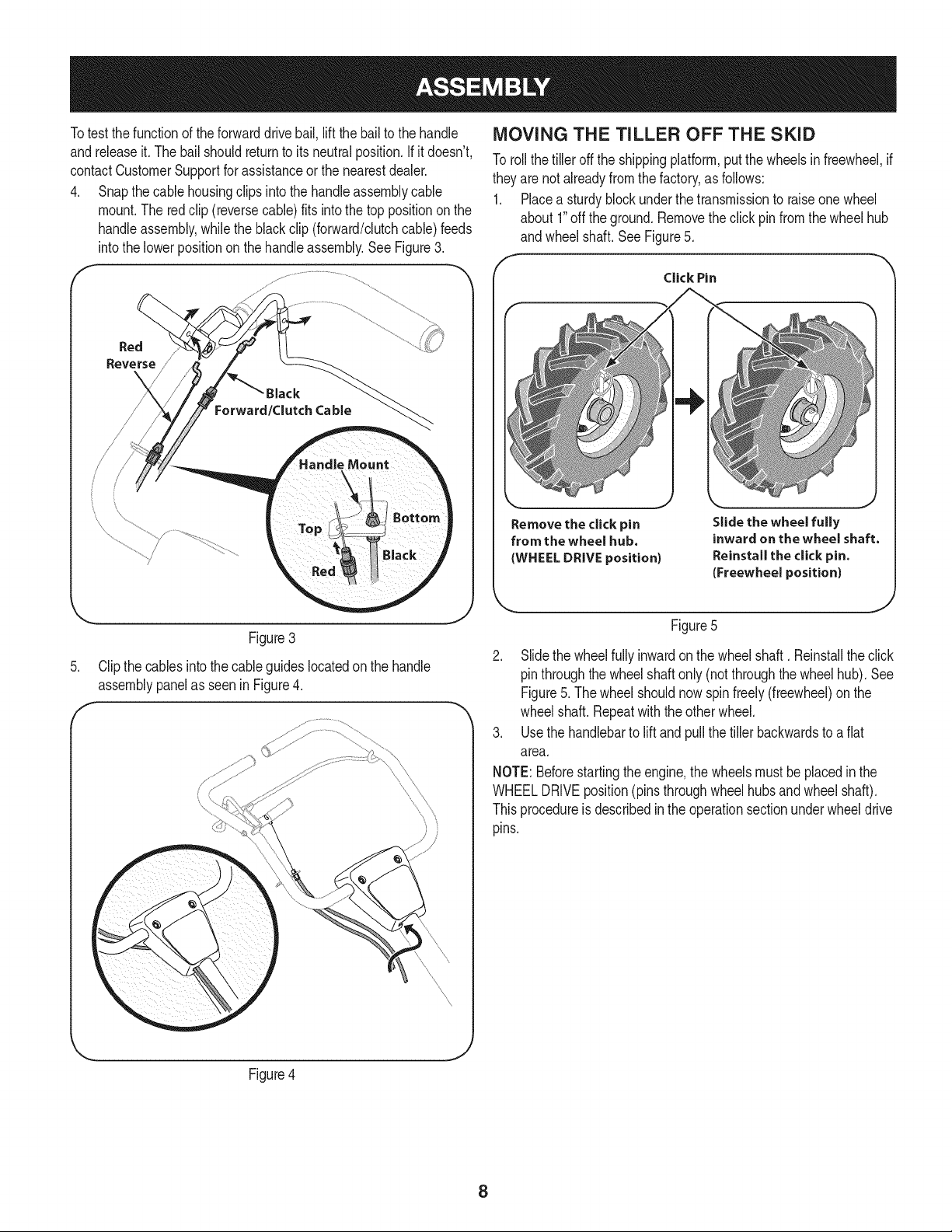
Totest thefunctionof theforwarddrive bail,lift the bailto the handle
andreleaseit. The bail shouldreturnto its neutralposition.Ifit doesn't,
contactCustomerSupportfor assistanceorthe nearestdealer.
4. Snapthe cablehousingclips intothe handleassemblycable
mount.The red clip (reversecable)fits into thetop positiononthe
handleassembly,whilethe black clip (forward/clutchcable)feeds
intothe lowerpositionon the handleassembly.See Figure3.
Red
Reverse
Figure3
Clipthe cablesintothe cableguideslocatedon the handle
assemblypanelas seenin Figure4.
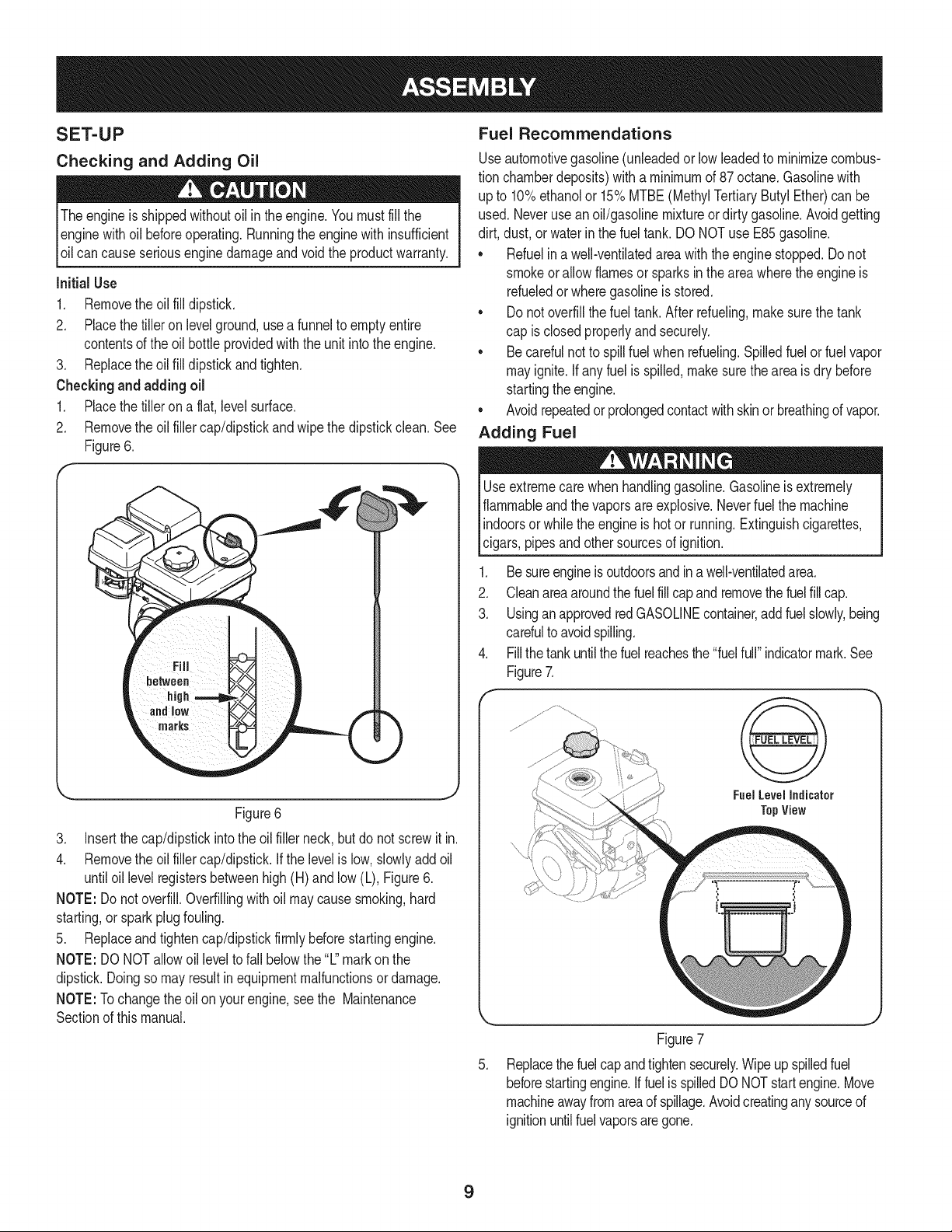
MOVING THE TILLER OFF THE SKID
To roll thetiller off the shippingplatform,put thewheels infreewheel,if
theyarenot alreadyfrom the factory,as follows:
1. Placea sturdyblockunderthe transmissionto raiseonewheel
about 1"off the ground.Removethe clickpin fromthe wheelhub
andwheelshaft. See Figure5.
f
Click Pin
Remove the click pin
from the wheel hub.
(WHEEL DRIVE position)
Slide the wheel fully
inward on the wheel shaft.
Reinstall the click pin.
(Freewheel position)
Figure5
2. Slidethe wheelfullyinwardonthe wheelshaft. Reinstallthe click
pinthroughthe wheelshaftonly (notthroughthe wheelhub). See
Figure5. Thewheel shouldnow spinfreely(freewheel)onthe
wheelshaft. Repeatwith theother wheel.
3. Usethe handlebarto lift and pull the tillerbackwardsto a flat
area.
NOTE:Beforestartingthe engine,the wheelsmustbe placedinthe
WHEELDRIVEposition(pinsthroughwheelhubsandwheel shaft).
Thisprocedureisdescribedinthe operationsectionunderwheeldrive
pins.
Figure4
J
8
SET-UP
Checking and Adding Oil
Theengine is shippedwithoutoil intheengine.Youmustfill the
enginewithoil beforeoperating.Runningthe enginewithinsufficient
_o can causeserous eng ne damageand vo d the productwarranty.
Initial Use
1. Removethe oil fill dipstick.
2. Placethetiller on levelground,usea funnelto emptyentire
contentsof the oil bottle providedwiththe unit intothe engine.
3. Replacethe oil fill dipstickandtighten.
Checkingand adding oil
1. Placethetiller ona flat, levelsurface.
2. Removethe oil fillercap/dipstickandwipethe dipstickclean.See
Figure6.
Figure6
3. Insertthe cap/dipstickintothe oil filler neck,butdo not screwitin.
4. Removethe oil fillercap/dipstick.If the levelislow,slowlyaddoil
untiloil levelregistersbetweenhigh(H) and low(L), Figure6.
NOTE: Donot overfill.Overfillingwithoil maycausesmoking,hard
starting,or sparkplugfouling.
5. Replaceandtightencap/dipstickfirmlybeforestartingengine.
NOTE: DONOTallowoil levelto fall belowthe"L"markon the
dipstick.Doingso mayresultinequipmentmalfunctionsordamage.
NOTE:Tochangethe oilon yourengine,see the Maintenance
Sectionof this manual.
Fuel Recommendations
Useautomotivegasoline(unleadedor lowleadedto minimizecombus-
tion chamberdeposits)with a minimumof 87 octane.Gasolinewith
up to 10%ethanolor 15%MTBE(MethylTertiaryButylEther)can be
used.Neverusean oil/gasolinemixtureor dirty gasoline.Avoidgetting
dirt, dust,or waterinthe fuel tank.DO NOTuse E85gasoline.
• Refuelin a well-ventilatedarea with the enginestopped.Do not
smokeor allowflamesor sparksin the areawherethe engineis
refueledor wheregasolineisstored.
• Donot overfillthe fueltank.After refueling,makesurethe tank
cap is closedproperlyandsecurely.
• Be carefulnotto spillfuel whenrefueling.Spilledfuel or fuel vapor
mayignite.If any fuelis spilled,makesurethe areaisdry before
startingthe engine.
• Avoidrepeatedor prolongedcontactwithskinor breathingof vapor.
Adding Fuel
Useextremecare whenhandlinggasoline.Gasolineisextremely
flammableandthevapors are explosive.Neverfuel the machine
indoorsorwhilethe engineishotor running.Extinguishcigarettes,
cigars,pipesandothersourcesof ignition.
1. Be sureengineis outdoorsandina well-ventilatedarea.
2. Cleanarea aroundthefuelfill capandremovethefuelfill cap.
3. UsinganapprovedredGASOLINEcontainer,addfuelslowly,being
carefulto avoidspilling.
4. Fillthe tank untilthe fuelreachesthe "fuelfull" indicatormark.See
Figure7.
Fuel Level Indicator
TopView
.
Figure7
Replacethe fuelcapandtightensecurely.Wipeupspilledfuel
beforestartingengine.IffuelisspilledDO NOTstartengine.Move
machineawayfromareaof spillage.Avoidcreatinganysourceof
ignitionuntilfuelvaporsaregone.
9
Transmission/Gear Oil
First Time Use
1. Withthetiller on levelground,pull the DepthRegulatorLever
backandthenall the wayup untilthe lowestnotchinthe leveris
engaged.SeeFigure8.
F
Depth Regulator Lever
Figure8
,
locatethe maindriveshaft situatedinsidethe housing.
SeeFigure9.
\
Removetheoil fill plugfromthetransmissionhousingcoverand
\
Figure9
3. Thegearoil levelis correctif the gear oil is approximatelyhalfway
upthe side of the maindriveshaft.
4. If theoil levelis low,referto the transmissiongear oil in the
ServiceandMaintenancesection.
10
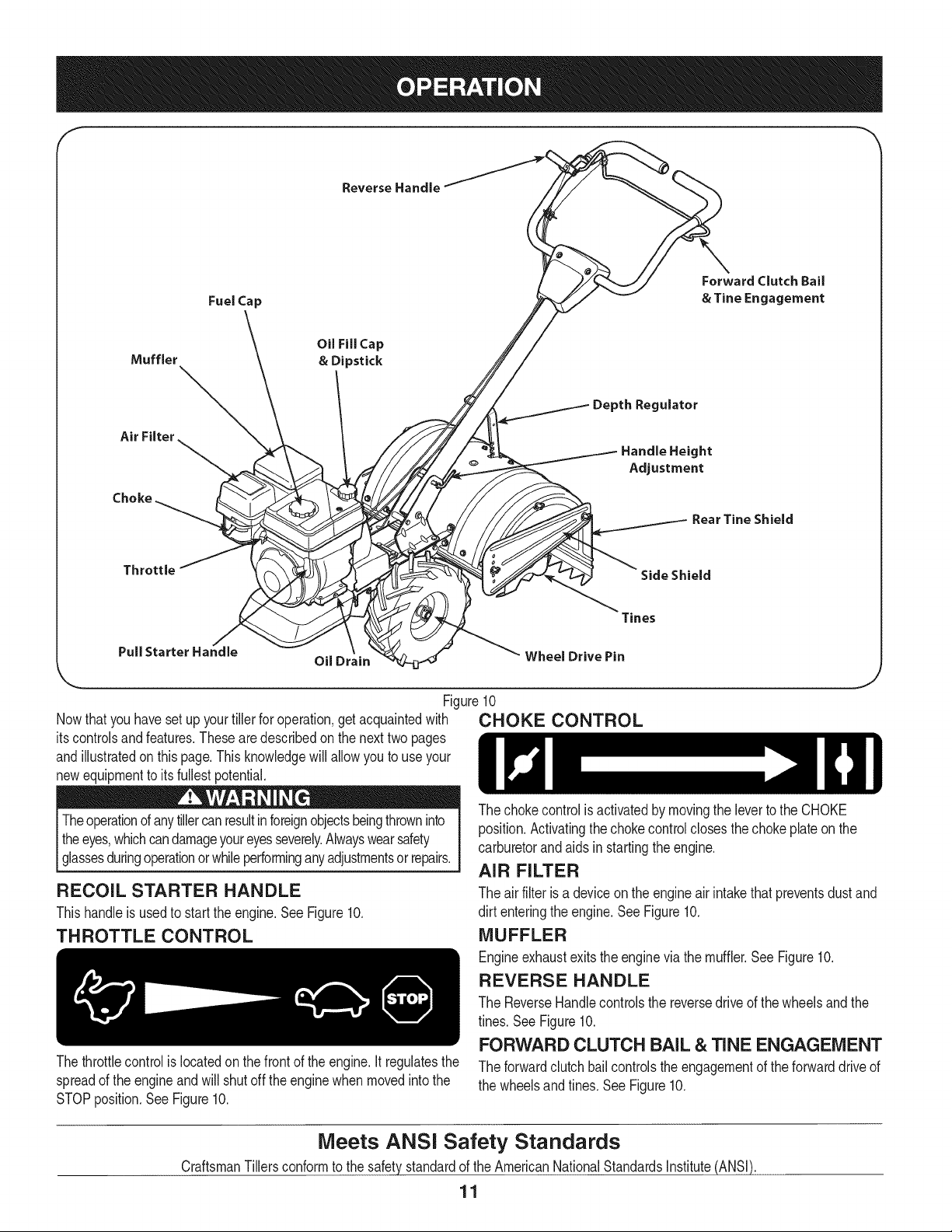
f
Forward Clutch Bail
Fuel Cap & Tine Engagement
Muffler
Air Filter
Choke
OU Fill Cap
& Dipstick
ulator
Handle Height
Adjustment
Rear Tine Shield
Throttle
Side Shield
Tines
Pull Starter Handle
Oil Drain
Wheel Drive Pin
Nowthat youhavesetup yourtillerfor operation,get acquaintedwith
itscontrolsand features.Thesearedescribedon the nexttwopages
andillustratedon thispage.This knowledgewill allowyou to useyour
newequipmentto itsfullestpotential.
Theoperationof anytillercanresultinforeignobjectsbeingthrowninto
theeyes,whichcandamageyoureyesseverely.Alwayswearsafety
[ g assesdurngoperaton or wh e performng anyadjustmentsorrepars.
RECOIL STARTER HANDLE
Thishandleisusedto startthe engine.See Figure10.
THROTTLE CONTROL
Figure10
CHOKE CONTROL
Thethrottlecontrolis locatedon thefront of theengine.It regulatesthe
spreadof the engineandwill shut off theenginewhen movedintothe
STOPposition.See Figure10.
,J
The chokecontrolisactivatedby movingthe leverto the CHOKE
position.Activatingthe chokecontrolclosesthe choke plateonthe
carburetorandaids instartingthe engine.
AIR FILTER
The air filter is a deviceon the engineair intakethat preventsdust and
dirt enteringthe engine.See Figure10.
MUFFLER
Engineexhaustexitsthe enginevia the muffler.See Figure10.
REVERSE HANDLE
The ReverseHandlecontrolsthe reversedriveof the wheelsandthe
tines. See Figure10.
FORWARD CLUTCH BAiL & TINE ENGAGEMENT
The forwardclutchbailcontrolsthe engagementof the forwarddriveof
the wheelsand tines.See Figure10.
Meets ANSi Safety Standards
CraftsmanTillersconformto the safetystandardof the AmericanNationalStandardsInstitute(ANSI).
11
OiL FiLL CAP & DIPSTICK
Engineoil levelcan be checkedand oiladdedthroughtheoil fill. See
Figure10.
NOTE:This unitwasshipped%THOUT oil inthe engine.Oilis
includedinthe plasticbag packedwiththe manualin with the unit.Add
the oil as directedinthe Assemblysection.Checkthe oil levelbefore
eachoperationto ensureadequateoil isinthe engine.Forfurther
instructions,referto thesteps inthe Serviceand Maintenancesection
of this manual.
DEPTH REGULATOR LEVER
Thislevercontrolsthe tillingdepthof the tines.Pull the leverbackand
slideit upor downto engagethe notchedheight.See Figure10.
HANDLEBAR HEIGHT ADJUSTMENT
Thehandlebarheightisadjustableto threedifferentsettings.In
general,adjustthe handlebarsso theyare at waistlevelwhenthe tines
are3-4" inthe ground.SeeFigure10.
REAR TIME SHIELD
The reartine shieldprotectsthe operatorfrom flyingdebriswhilealso
smoothingout freshlytilledsoil.SeeFigure10.
SiDE SHIELD
Theside shieldisusedto maintainclearevenrowsandmaybe
adjustedto oneof fivedifferentpositions.SeeFigure10.
TINES
Yourtiller'stinesarea seriesof hoesarrangedona revolvingpower-
drivenshaft.See Figure10.
WHEEL DRIVE PiNS
Eachwheelisequippedwitha wheeldriveclick pin that securesthe
wheelto thewheel shaft.The wheelscanbe positionedineither a
WHEELDRIVEor a FREEWHEELmode.See Figure10.
OiL DRAIN
Removingthe oildrainplugwill drainthe oil fromthe engine.See
Figure10.
TO START ENGINE
1. Attachsparkplug wireand rubberbootto sparkplug.
2. Fill tankto nomorethan 1/2 inchbelowbottomof fillerneckto
providespacefor fuel expansion.
3. Putthe wheelsin the WHEELDRIVEposition.
4. Movethe DepthRegulatorLeverall the waydownto the"trans-
port" position,so thatthe tinesclear theground.
5. Releaseall of the controlsonthe tiller.
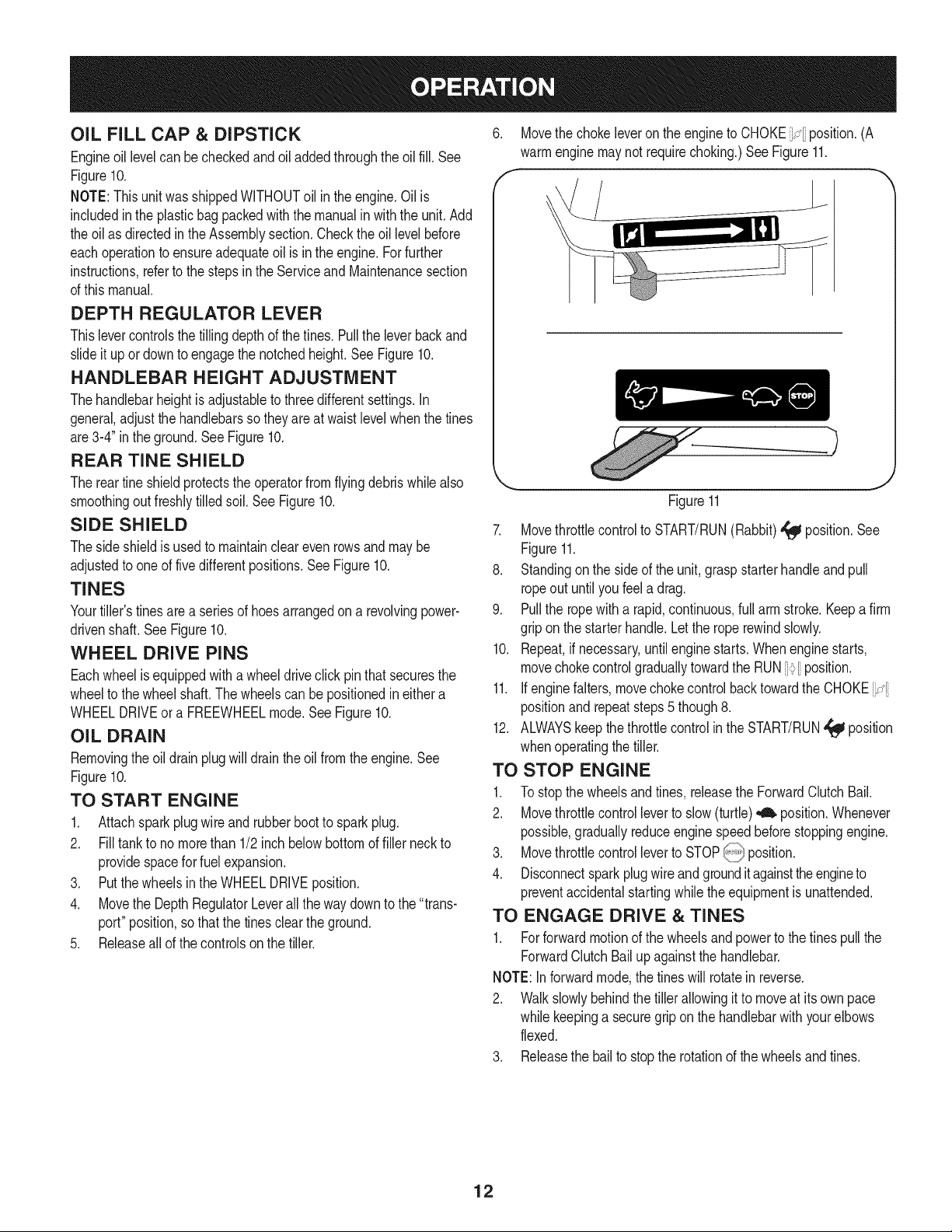
6. Movethe chokeleveron the engineto CHOKE_÷ position.(A
warmenginemaynotrequirechoking.)See Figure11.
f -,
_.. .J
Figure11
7. Movethrottlecontrolto START/RUN(Rabbit)_ position.See
Figure11.
8. Standingon the sideof the unit,graspstarterhandleandpull
ropeout untilyou feela drag.
9. Pullthe ropewitha rapid,continuous,full arm stroke.Keepafirm
gripon the starterhandle.Letthe roperewindslowly.
10. Repeat,if necessary,untilenginestarts.Whenenginestarts,
movechokecontrolgraduallytowardthe RUN_[ position.
11. If enginefalters, movechokecontrolbacktowardthe CHOKEi:_
positionand repeatsteps5 though8.
12. ALWAYSkeepthe throttlecontrolin theSTART/RUN,_ position
whenoperatingthe tiller.
TO STOP ENGINE
1. To stopthe wheelsandtines, releasethe ForwardClutchBail.
2. Movethrottlecontrolleverto slow(turtle)_ position.Whenever
possible,graduallyreduceenginespeedbeforestoppingengine.
3. Movethrottlecontrolleverto STOP_ position.
4. Disconnectspark plugwireandgroundit againsttheengineto
preventaccidentalstartingwhilethe equipmentis unattended.
TO ENGAGE DRIVE & TINES
1. Forforwardmotionof the wheelsandpowerto the tinespullthe
ForwardClutchBailupagainstthe handlebar.
NOTE:Inforwardmode,the tines will rotatein reverse.
2. Walk slowlybehindthetiller allowingit to moveat itsown pace
while keepinga securegrip on the handlebarwithyourelbows
flexed.
3. Releasethe bailto stop the rotationof the wheelsand tines.
12
To move tiller in reverse: (Do not till in reverse)
a. Releasethe ForwardClutchBail.
b. Lift the handlebaruntilthe tinesare offthe ground.
c. Slowlypull backonthe ReverseLever,andcarefullywalk
backwardswiththe machine.
NOTE:In reversemode,the tineswill rotateforward.
d. If longerdistancesneedto be coveredinreverse,shutoff the
engine,thenplacethe twowheels inFREEWHEEL.
TURNING THE TILLER
1. Practiceturningthetiller in a level,open area.Beverycarefulto
keepyourfeetandlegs awayfromthe tines.
2. To begina turn,liftthe handlebarsuntilthe tinesareout of the
groundandthe engineand tines are balancedoverthe wheels.
3. With the tillerbalanced,pushsidewayson the handlebarto steer
inthe directionof the turn.Afterturning,slowlylowerthe tinesinto
the soil to resumetilling.
SETTING THE DEPTH
Becertainsparkplugwire isdisconnectedandgroundedagainstthe
enginewhenperforminganyadjustments.
Tillingdepthis controlledbythedepthstakewhichcanbeadjustedto five
differentsettings.Adjustthesideshieldsas youadjustthedepthstake.
• Whenusingthe tillerfor the firsttime, usethe secondadjustment
holefromthetop (1"of tillingdepth).
• Whenbreakingup sodand for shallowcultivation,usethe setting
whichgives1"of tillingdepth (secondholefromthe top). Place
the sideshieldsintheir lowestposition.
• Forfurtherdepth,raisethe depthstakeand side shieldsandalso
makeoneor twomorepassesoverthearea.
• Whentillingloosesoil,the depthstakemay be raisedto its
highestposition(use bottomadjustmenthole)to givethe deepest
tillingdepth. Raisethe sideshieldsto their highestposition.
• Totransporttiller,lowerthedepthstake(usetopadjustmenthole).
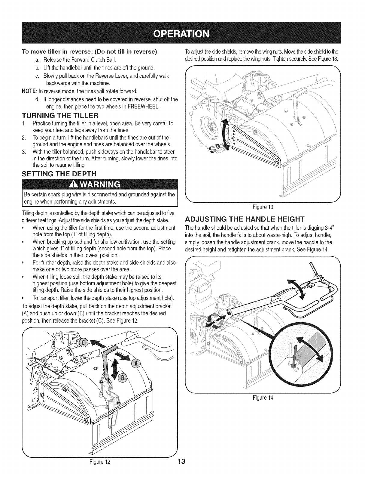
Toadjust thedepthstake,pull backon thedepth adjustmentbracket
(A)and pushup or down(B) untilthe bracketreachesthe desired
position,then releasethe bracket(C). SeeFigure12.
Toadjustthesideshields,removethewingnuts.Movethesideshieldto the
desiredpositionand replacethewingnuts.Tightensecurely.SeeFigure13.
f ---
\
\ j
Figure13
ADJUSTING THE HANDLE HEIGHT
The handleshouldbeadjustedsothat whenthe tiller is digging3-4"
intothe soil, thehandlefallsto aboutwaste-high.Toadjusthandle,
simplyloosenthe handleadjustmentcrank,movethe handleto the
desiredheightand retightenthe adjustmentcrank.See Figure14.
Figure14
J
Figure12 13
CLEARING THE TINES
Beforeclearingthetinesby hand,stoptheengine,allowall moving
partsto stop and disconnectthe sparkplug wire. Failureto followthis
warningcouldresult in personalinjury.
* Thetines havea self-clearingaction whicheliminatesmostof the
tanglingof debris. However,occasionallydry grass,stringystalks
ortough vinesmay becometangled.Followtheseproceduresto
helpavoidtanglingand to clearthe tines, ifnecessary.
* To reducetangling,setthedepth regulatordeepenoughto get
maximum"chopping"actionas the tineschopthe materialagainst
the ground.Also, try to till undercrop residuesor covercrops
whilethey are green,moistand tender.
* Whiletilling,try swayingthe handlebarsfromsideto side(about
6" to 12").This"fishtailing"action oftenclears the tinesof debris.
TILLING TiPS & TECHNIQUES
Beforetilling,contactyourtelephoneor utilitiescompanyandinquire
l ifundergroundequipmentor linesare usedon yourproperty.Do not
[till nearburiedelectriccables,telephonelines, pipesor hoses.
Tilling Depth
* Thisisa CRT(counter-rotatingtine)tiller.As thewheelspull
forward,the tines rotatebackward.Thiscreatesan "uppercut"
tine actionwhich digsdeeply,uprootingsoilandweeds.Don't
overloadtheengine,but digas deeplyas possibleon eachpass
On laterpasses,the wheelsmay tendto spin inthe soft dirt. Help
themalongby lifting up slightlyonthe handlebar(onehand,palm
up, worksmosteasily).
* Avoidthetemptationto pushdown on the handlebarsin an
attemptto force thetiller to digdeeper.Doingso takesthe weight
off the poweredwheels,causingthemto losetraction.Withoutthe
wheelsto hold the tiller back,the tineswill attemptto propelthe
tiller backward,towardsthe operator.
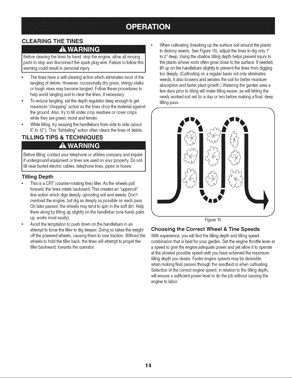
Whencultivating(breakingupthe surfacesoil aroundthe plants
to destroyweeds,See Figure15),adjustthe tinesto digonly 1"
to 2" deep. Usingthe shallowtillingdepthhelpspreventinjuryto
the plantswhose rootsoften growcloseto the surface.Ifneeded,
liftupon the handlebarsslightlyto preventthe tinesfromdigging
too deeply.(Cultivatingon a regularbasisnot onlyeliminates
weeds,it also loosensandaeratesthe soil for bettermoisture
absorptionandfasterplantgrowth.)Wateringthegardenareaa
fewdayspriortotilling will maketillingeasier,aswill lettingthe
newlyworkedsoil setfor a dayor twobeforemakinga final, deep
tilling pass.
Figure15
Choosing the Correct Wheel & Tine Speeds
Withexperience,you willfind thetilling depthand tillingspeed
combinationthat is bestfor yourgarden.Setthe enginethrottleleverat
a speedto givethe engineadequatepowerandyet allowit to operate
at the slowestpossiblespeeduntilyou haveachievedthe maximum
tillingdepthyou desire.Fasterenginespeedsmaybe desirable
whenmakingfinal passesthroughtheseedbedor whencultivating.
Selectionof the correctengine speed,in relationto thetilling depth,
will ensurea sufficientpowerlevelto do thejobwithoutcausingthe
engineto labor.
14
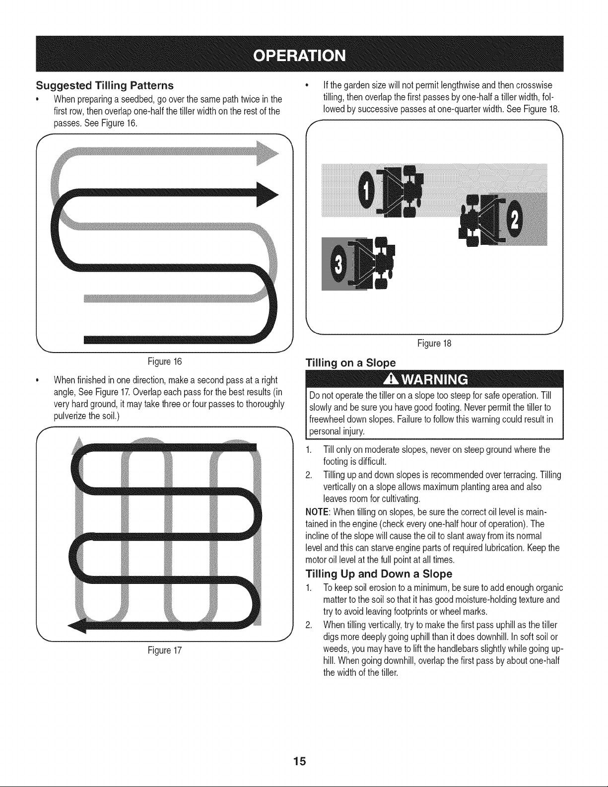
Suggested Tilling Patterns
• Whenpreparinga seedbed,gooverthe samepathtwice in the
first row,thenoverlapone-halfthetiller width on the restof the
passes.SeeFigure16.
f
Figure16
Whenfinishedin one direction,makea second passat a right
angle,See Figure17.Overlapeach passfor the bestresults(in
veryhardground,it maytakethreeor four passesto thoroughly
pulverizethe soil.)
m m m m
r
t_ m _ m
Figure17
J
f
Ifthe gardensize will notpermit lengthwiseandthencrosswise
tilling,thenoverlapthe first passesby one-halfa tiller width,fol-
lowedby successivepassesat one-quarterwidth.See Figure18.
Figure18
Tilling on a Slope
Donotoperatethetiller on a slopetoo steepfor safeoperation.Till
slowlyand be sureyou havegoodfooting.Neverpermitthe tillerto
freewheeldownslopes.Failureto followthiswarningcould resultin
personalinjury.
1. Till onlyon moderateslopes,neveron steepgroundwherethe
footingisdifficult.
2. Tillingupand downslopesis recommendedoverterracing.Tilling
verticallyon aslopeallows maximumplantingareaandalso
leavesroomfor cultivating.
NOTE:Whentillingon slopes,be surethe correctoil levelis main-
tainedin theengine(checkeveryone-halfhourof operation).The
inclineof the slopewill causethe oilto slantawayfromits normal
leveland this canstarveengineparts of requiredlubrication.Keepthe
motoroil levelat the full pointat all times.
Tilling Up and Down a Slope
1. To keepsoilerosionto a minimum,besureto addenoughorganic
matterto the soil sothat it has goodmoisture-holdingtextureand
try to avoidleavingfootprintsor wheelmarks.
2. Whentillingvertically,try to makethe first passuphillas thetiller
digs moredeeplygoinguphillthanit doesdownhill.Insoft soil or
weeds,youmayhaveto liftthe handlebarsslightlywhilegoingup-
hill. Whengoingdownhill,overlapthefirst passby aboutone-half
the width of the tiller.
15
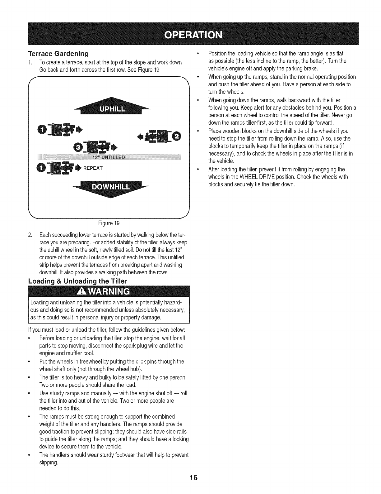
Terrace Gardening
1. Tocreatea terrace,start at thetop of the slopeandworkdown
Gobackandforthacrossthe first row.See Figure19.
f
• Positionthe loadingvehicleso that the rampangleis as flat
as possible(the lessinclineto the ramp,the better).Turnthe
vehicle'sengineoff andapplythe parkingbrake.
• Whengoingupthe ramps,standin the normaloperatingposition
and pushthetiller aheadof you.Havea personat each sideto
turn the wheels.
• Whengoingdownthe ramps,walkbackwardwith the tiller
followingyou.Keepalertfor anyobstaclesbehindyou.Positiona
personat eachwheelto controlthe speedof the tiller.Nevergo
downthe rampstiller-first,as the tillercouldtip forward.
• Placewoodenblockson thedownhillsideof the wheelsif you
needto stop the tillerfrom rollingdownthe ramp.Also, usethe
blocksto temporarilykeepthe tiller in placeon the ramps(if
necessary),and to chockthe wheelsin placeafterthe tiller is in
the vehicle.
• After loadingthe tiller,preventit from rollingby engagingthe
wheelsinthe WHEELDRIVEposition.Chockthe wheelswith
blocksandsecurelytie the tillerdown.
J
Figure19
2. Eachsucceedinglowerterraceis startedbywalkingbelowtheter-
raceyouarepreparing.Foraddedstabilityof thetiller,alwayskeep
theuphillwheelin thesoft,newlytilledsoil.Donottill thelast 12"
ormored the downhilloutsideedgeof eachterrace.This untilled
striphelpspreventthe terracesfrombreakingapartand washing
downhill.It alsoprovidesa walkingpathbetweenthe rows.
Loading & Unloading the Tiller
Loadingandunloadingthe tiller intoa vehicleis potentiallyhazard-
ous and doing so is not recommendedunlessabsolutelynecessary,
as thiscouldresult in personalinjuryor propertydamage.
If youmustloador unloadthe tiller,followthe guidelinesgiven below:
• Beforeloadingor unloadingthe tiller,stop the engine,waitforall
partsto stop moving,disconnectthe sparkplug wireandlet the
engineandmufflercool.
• Putthe wheelsin freewheelby puttingthe clickpins throughthe
wheelshaftonly (notthroughthe wheelhub).
• Thetiller is too heavyand bulky to be safelyliftedby one person.
Twoor morepeopleshouldsharethe load.
• Use sturdyrampsandmanually-- with theengineshutoff -- roll
the tillerintoand outof the vehicle.Twoor morepeopleare
neededto do this.
• The rampsmustbe strongenoughto supportthe combined
weightof the tillerand any handlers.The rampsshouldprovide
goodtractionto preventslipping;theyshouldalso havesiderails
to guidethe tiller alongthe ramps;and they shouldhavea locking
deviceto securethem to the vehicle.
• Thehandlersshouldwearsturdyfootwearthat will helpto prevent
slipping.
16
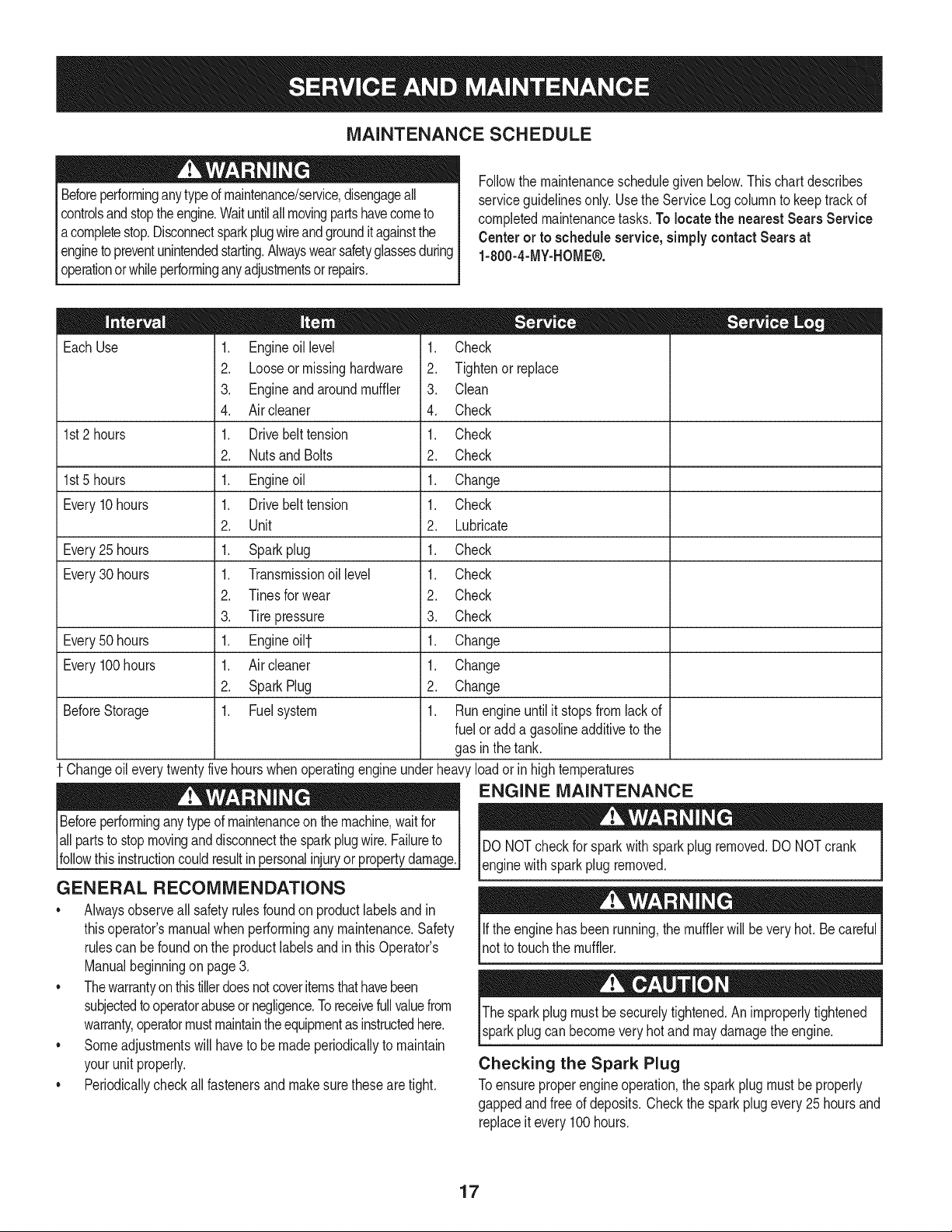
MAINTENANCE SCHEDULE
Beforeperforminganytypeof maintenance/service,disengageall
controlsandstoptheengine.Waituntilall movingpartshavecometo
acompletestop.Disconnectsparkplugwireandgrounditagainstthe
enginetopreventunintendedstarting.Alwayswearsafetyglassesduring
operationor whileperforminganyadjustmentsor repairs.
Followthe maintenanceschedulegivenbelow.This chart describes
serviceguidelinesonly. Usethe ServiceLogcolumnto keeptrackof
completedmaintenancetasks.To locate the nearest Sears Service
Centeror to scheduleservice,simplycontactSears at
1-800-4-MY-HOME®.
EachUse
1st2 hours
1st5 hours
Every10hours
Every25 hours
Every30 hours
Every50 hours
Every100hours
BeforeStorage
1. Engineoil level
2. Looseormissinghardware
3. Engineand aroundmuffler
4. Air cleaner
1. Drivebelt tension
2. Nutsand Bolts
1. Engineoil
1. Drivebelt tension
2. Unit
1. Sparkplug
1. Transmissionoil level
2. Tinesfor wear
3. Tirepressure
1. Engineoi11-
1. Air cleaner
2. SparkPlug
1. Fuelsystem
= =
1. Check
2. Tightenor_place
3. Clean
4. Check
1. Check
2. Check
1. Change
1. Check
2. Lubricate
1. Check
1. Check
2. Check
3. Check
1. Change
1. Change
2. Change
1. Runengineuntilit stopsfromlackof
fuel or add a gasolineadditiveto the
gas in thetank.
Changeoileverytwentyfivehourswhenoperatingengineunderheavyloadorin hightemperatures
ENGINE MAINTENANCE
Beforeperforminganytypeof maintenanceon themachine,waitfor
allpartsto stopmovinganddisconnectthe sparkplugwire.Failureto
followthis instructioncouldresultinpersonalinjuryorpropertydamage.
GENERAL RECOMMENDATIONS
• Alwaysobserveall safety rulesfoundon productlabelsandin
thisoperator'smanualwhenperformingany maintenance.Safety
rulescan befoundon the productlabelsandin this Operator's
Manualbeginningon page3.
• Thewarrantyonthistillerdoesnotcoveritemsthathavebeen
subjectedtooperatorabuseor negligence.Toreceivefullvaluefrom
warranty,operatormustmaintaintheequipmentasinstructedhere.
• Someadjustmentswillhaveto be madeperiodicallyto maintain
yourunit properly.
• Periodicallycheckall fastenersand makesurethesearetight.
DO NOTcheckfor sparkwith spark plug removed.DO NOTcrank
enginewithsparkplug removed.
Ifthe enginehas beenrunning,the mufflerwill beveryhot. Becareful
notto touchthe muffler.
Thespark plug mustbesecurelytightened.Animproperlytightened
sparkplugcan becomeveryhot and may damagethe engine.
Checking the Spark Plug
Toensureproperengineoperation,the sparkplugmustbe properly
gappedandfree of deposits.Checkthe sparkplugevery25hoursand
replaceitevery 100 hours.
17
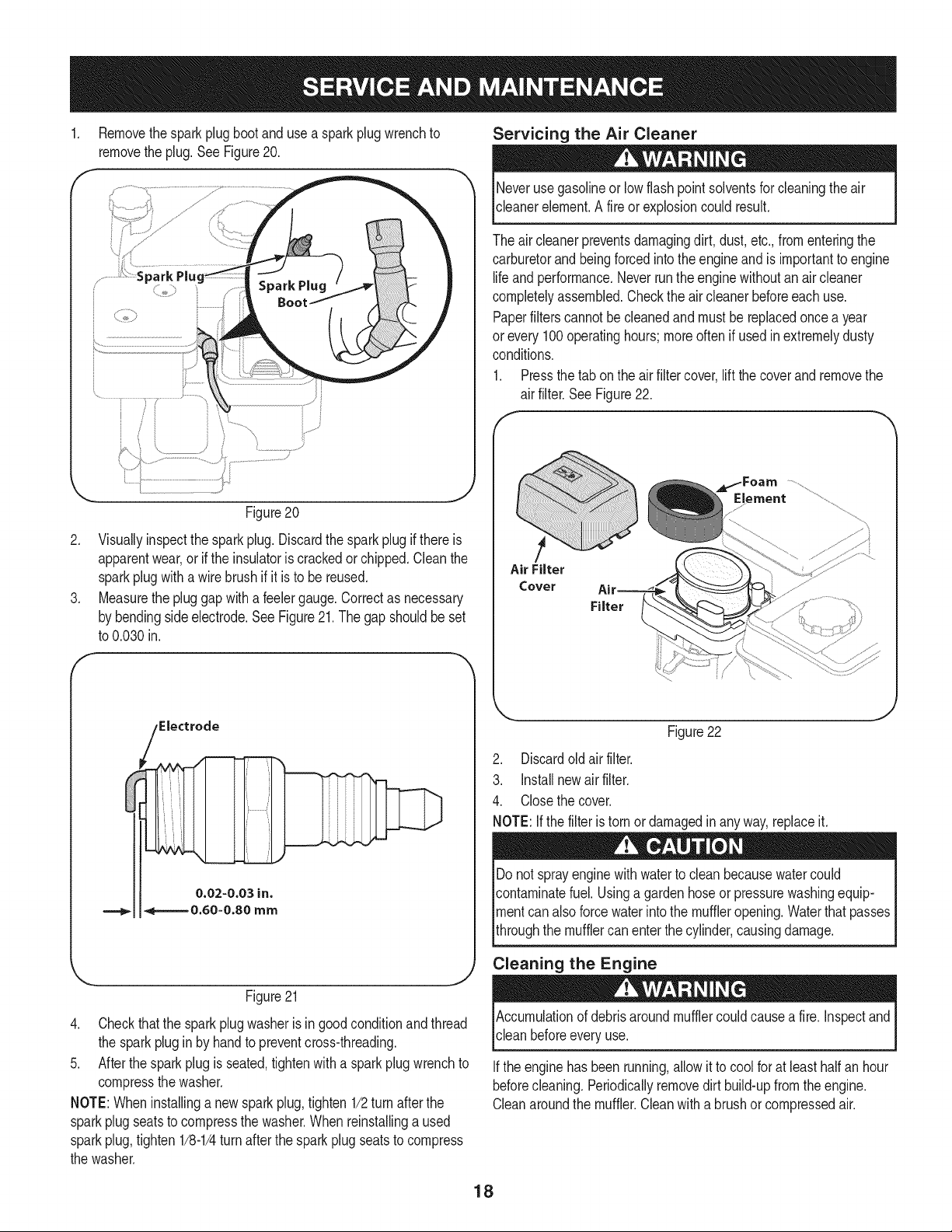
Removethespark plug bootanduse a sparkplug wrenchto
removethe plug.See Figure20.
Figure20
2. Visuallyinspectthe sparkplug.Discardthe sparkplugif thereis
apparentwear,orif the insulatoris crackedor chipped.Cleanthe
sparkplugwitha wirebrush if it is to be reused.
3. Measurethe plug gap with a feelergauge.Correctas necessary
by bendingsideelectrode.SeeFigure21.The gapshouldbeset
to 0.030in.
Electrode
0.02-0.03 in.
===_ 4=======0.60-0.80 mm
Servicing the Air Cleaner
Neverusegasolineor lowflashpoint solventsfor cleaningtheair
cleanerelement.A fireor explosioncould result.
The air cleanerpreventsdamagingdirt, dust,etc.,fromenteringthe
carburetorandbeing forcedintothe engineand is importantto engine
lifeand performance.Neverrunthe enginewithoutanair cleaner
completelyassembled.Checkthe air cleanerbeforeeachuse.
Paperfilterscannotbecleanedand mustbe replacedoncea year
or every100operatinghours;moreoftenif usedinextremelydusty
conditions.
1. Pressthetab on the air filtercover,lift the coverand removethe
air filter.See Figure22.
Air Filter
Cover
Filter
_Foam .....................
Element ............
Figure22
2. Discardoldair filter.
3. installnewair filter.
4. Closethe cover.
NOTE:If the filteris tornor damagedinany way,replaceit.
Do notsprayenginewithwaterto cleanbecausewatercould
contaminatefuel.Usinga gardenhoseor pressurewashingequip-
mentcan alsoforcewaterintothe muffleropening.Waterthatpasses
throughthe mufflercan enterthe cylinder,causingdamage.
Cleaning the Engine
Figure21
4. Checkthatthe sparkplugwasheris in good conditionand thread
the sparkplug in by handto preventcross-threading.
5. After thesparkplugis seated,tightenwith a spark plugwrenchto
compressthe washer.
NOTE:Wheninstallinga newsparkplug,tighten 1/2turn afterthe
sparkplugseatsto compressthe washer.Whenreinstallinga used
sparkplug,tighten 1/8-1/4turnafterthe spark plug seatsto compress
the washer.
Accumulationof debrisaroundmufflercouldcausea fire. inspectand
clean beforeevery use.
Ifthe enginehas beenrunning,allow it to coolfor at leasthalf an hour
beforecleaning.Periodicallyremovedirt build-upfrom the engine.
Cleanaroundthe muffler.Cleanwitha brushor compressedair.
18
Check Engine Oil
1. Checkoil beforeeachuse. Stopengineandwaitseveralminutes
beforecheckingoil level.Withthe tilleron levelground,the oil
mustbe to FULLmarkon dipstick.
2. Removeoil fill dipstickand wipe cleanwith cloth.
3. Replacedipstickintothe oilfiller neck,but do not screwitin.
Removeand checkoil level.Levelshouldbe at FULLmark.
4. If needed,add oil slowly- recheck.Do not overfill.
5. Wipedipstickclean,replacebut do not tighten.Removeand
checkoil level.Oil levelshouldbe at FULLline on dipstick.
6. Replaceandtightendipstickfirmlybeforestartingengine.
Change Engine Oil
DO NOTuse non-detergentoilor 2-strokeengineoil. Itcould shorten
the engine'sservicelife.
Refertotheviscositychart(Figure23)foroil recommendations.SAE
10W-30is recommendedforgeneral,all temperatureuse.When
addingoilto theengine,referto viscositychartintheoperationsec-
tion.Usea4-stroke,oranequivalenthighdetergent,premiumquality
motoroilcertifiedto meetorexceedU.S.automobilemanufacturer's
requirementsforserviceclassificationSG,SE Motoroilsclassified
SG,SFwillshowthisdesignationonthecontainer.
2
I.-
0
_J _j
_u
uqo_
I--
m
m
m
!
m
(°C) -30° -20° -10° 0° 10° 200 300 400
(oF)-20 o 0o 150 300 500 700 850 1050
Figure23
Changeengineoil afterthefirst fiveto eight hoursof operation,
andeveryfifty hoursor every seasonthereafter.Changeoil every
twentyfivehourswhenoperatingengineunderheavyloadorin
hightemperatures.
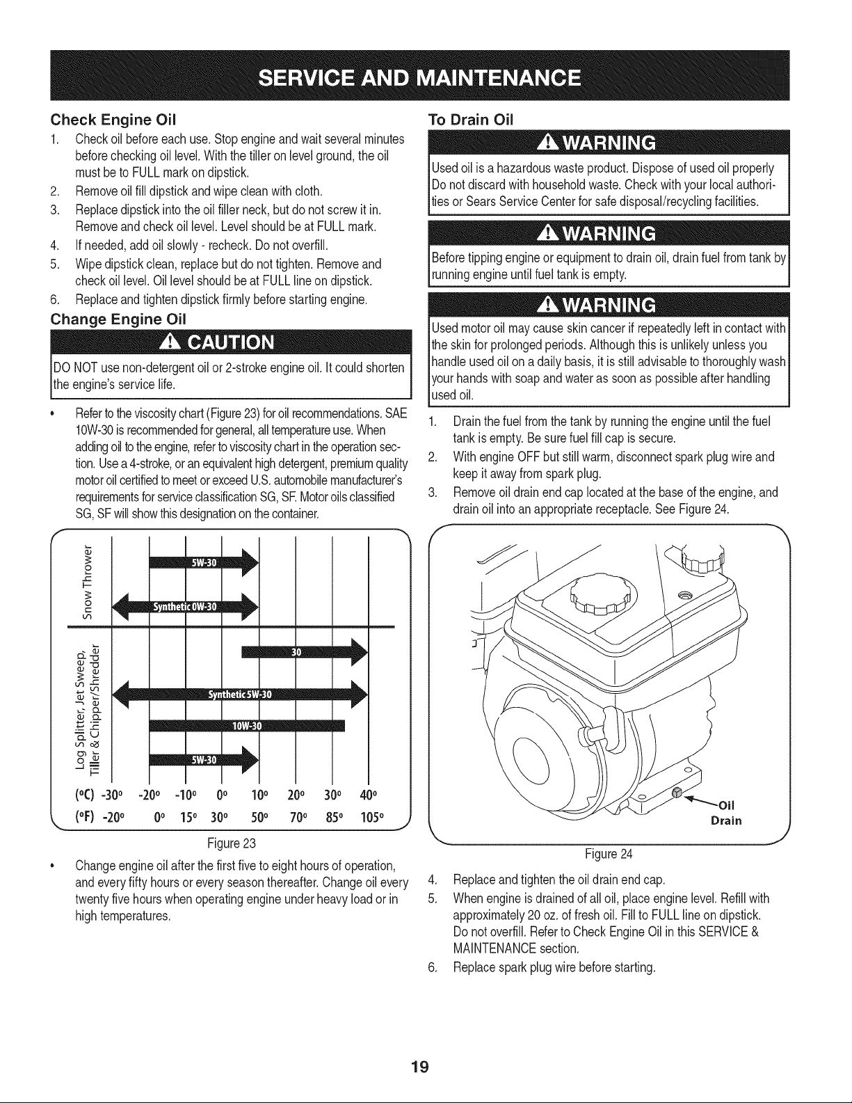
To Drain Oil
Usedoil is a hazardouswasteproduct.Disposeof usedoil properly
IDo notdiscardwith householdwaste.Checkwithyour localauthori-
lties or SearsServiceCenterfor safedisposal/recyclingfacilities.
Beforetippingengineorequipmentto drainoil, drainfuelfrom
runningengineuntilfuel tank isempty.
Usedmotoroil maycauseskincancerif repeatedlyleft incontactwith
the skinfor prolongedperiods.Althoughthis isunlikelyunlessyou
handleusedoil on a dailybasis,it is still advisableto thoroughlywash
yourhandswithsoapand wateras soonas possibleafterhandling
usedoil.
1. Drainthe fuel fromthe tankby runningthe engineuntilthe fuel
tankisempty. Be surefuelfill cap is secure.
2. With engine OFFbut stillwarm,disconnectsparkplugwireand
keep itawayfromsparkplug.
3. Removeoil drainend cap locatedat the baseof the engine,and
drainoil intoan appropriatereceptacle.See Figure24.
f -,,,
.
5.
Drain
J
Figure24
Replaceandtightenthe oildrainendcap.
Whenengine isdrainedof all oil, placeenginelevel. Refillwith
approximately20oz.of fresh oil. Fillto FULLline on dipstick.
Donot overfill.Referto CheckEngineOil inthis SERVICE&
MAINTENANCEsection.
6. Replacesparkplugwire beforestarting.
19
Check Transmission Gear Oil
Checkthetransmissiongear oil after every 30 hoursof operation
orwheneveryou noticeanyoil leak. Operatingthe tiller whenthe
transmissionis lowon oil can resultin severedamage.
ToCheckthe TransmissionGearOil Level:
1. Checkthegearoil levelwhenthetransmissionis cool.Gearoil
will expandin warm operatingtemperaturesand this expansion
will providean incorrectoil levelreading.
2. With thetiller on levelground,pullthe DepthRegulatorLeverall
the wayup
3. Removetheoil fill plug from thetransmissionhousingand look
insidethe oilfill hole to locatethemaindrive shaftsituatedbelow
the hole.SeeFigure25.
\
J
Figure25
4. Thegearoil levelis correctif the gear oil is approximatelyhalfway
upthe side of the maindriveshaft.
5. If thegearoil levelis low,add gearoil as describednext.Ifthe
gearoillevelis okay,securelyreplacethe oil fill plug.
6. If addingonlya fewouncesof gear oil, useAPI ratedGb4 or
Gb5 gearoil havinga viscosityof SAE 140,SAE85%140 or SAE
80W-90.ifrefillinganemptytransmission,useonly Gb4 gear oil
havinga viscosityof SAE 85W-140or SAE 140.
7. Whilecheckingfrequentlyto avoidoverfilling,slowlyaddgearoilinto
theoilfill holeuntilit reachesthehalfwaypointonthedriveshaft.
8. Securelyreplacetheoil fill plug.
Change Transmission Gear Oil
Thetransmissiongearoildoes not needto be changedunlessit has
beencontaminatedwithdirt, sandor metalparticles.See an autho-
rizedSearsServiceCenterto havethetransmissiongearoil changed
orto scheduleservice,simplycontactSearsat 1-800-4-MY-HOME®.
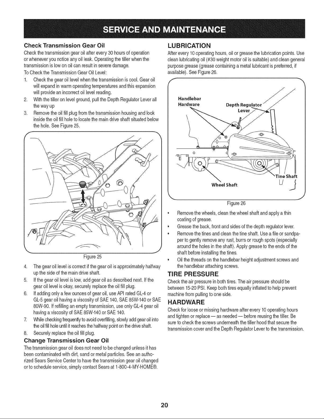
LUBRICATION
Afterevery10operatinghours,oil or greasethe lubricationpoints.Use
clean lubricatingoil (#30 weight motoroil is suitable)andcleangeneral
purposegrease(greasecontaininga metal lubricantis preferred,if
available).SeeFigure26.
Handlebar
Hardware Depth Reg_
Wheel Shaft
Tine Shaft
Figure26
• Removethe wheels,cleanthe wheelshaftand applya thin
coatingof grease.
• Greasethe back,frontandsidesof the depthregulatorlever.
• Removethe tines and cleanthefine shaft.Usea fileor sandpa-
perto gentlyremoveany rust,burrsor roughspots(especially
aroundthe holesin the shaft).Applygreaseto the endsof the
shaftbeforeinstallingthetines.
• Oil thethreadson the handlebarheightadjustmentscrewsand
the handlebarattachingscrews.
TIRE PRESSURE
Checkthe air pressurein both tires.Theair pressureshouldbe
between15-20PSI.Keepbothtiresequallyinflatedto helpprevent
machinefrompullingto oneside.
HARDWARE
Checkfor looseor missinghardwareafter every 10 operatinghours
andtightenor replace= as needed= beforereusingthe tiller.Be
sureto checkthe screwsunderneaththe tiller hoodthat securethe
transmissioncoverand the DepthRegulatorLeverto the transmission.
2O
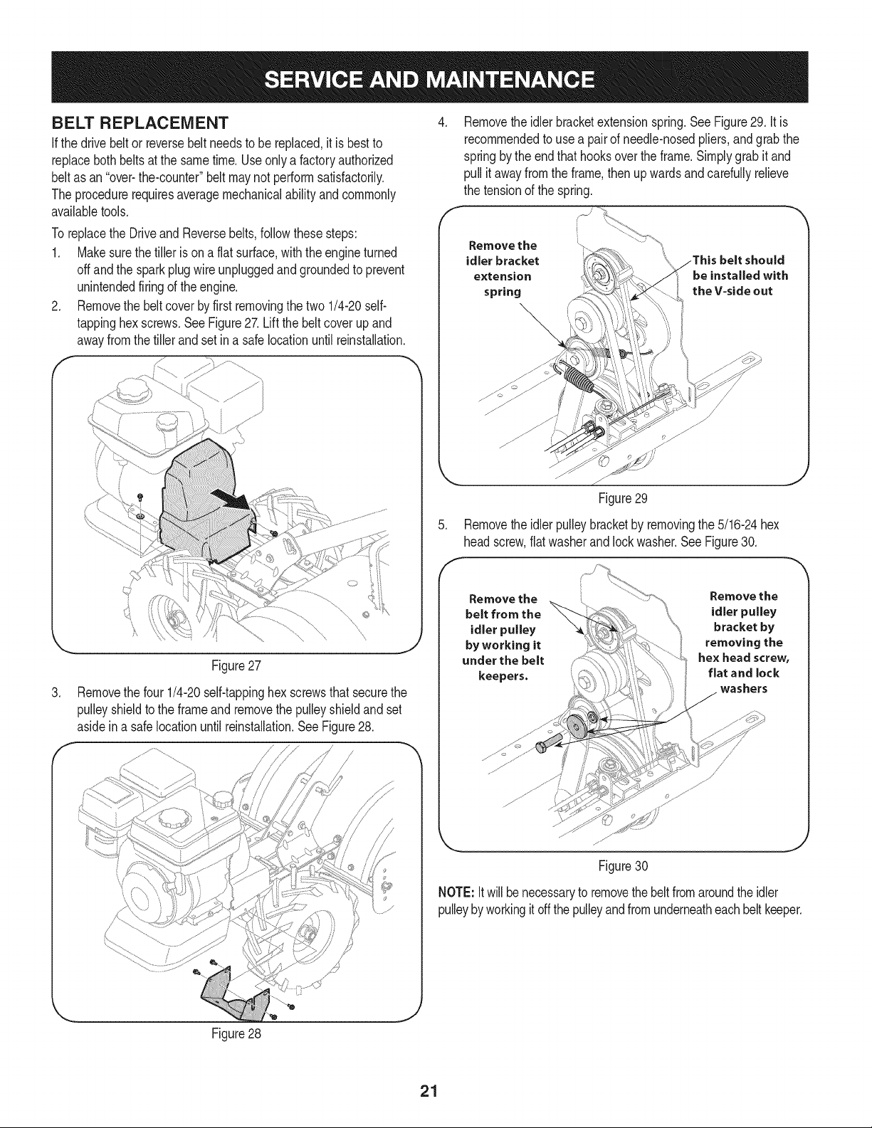
BELT REPLACEMENT
Ifthe drive beltor reversebeltneedsto be replaced,itis bestto
replacebothbeltsat the sametime.Use onlya factoryauthorized
beltas an "over-the-counter"beltmaynot performsatisfactorily.
The procedurerequiresaveragemechanicalabilityandcommonly
availabletools.
To replacethe DriveandReversebelts,followthesesteps:
1. Makesurethe tiller is on a flat surface,withthe engineturned
offandthe sparkplugwireunpluggedandgroundedto prevent
unintendedfiringof the engine.
2. Removethe beltcoverby first removingthe two 1/4-20self-
tappinghexscrews.SeeFigure27. Liftthe beltcoverup and
awayfromthetiller andsetin a safelocationuntilreinstallation.
f
.
Figure27
Removethe four 1/4-20self-tappinghexscrewsthatsecurethe
pulleyshieldtothe frameandremovethe pulleyshieldandset
asidein a safelocationuntil reinstallation.SeeFigure28.
/
Figure28
J
.
Removethe idlerbracketextensionspring.SeeFigure29. It is
recommendedto usea pairof needle-nosedpliers,andgrabthe
springby the end that hooksoverthe frame.Simplygrabit and
pull it awayfrom the frame,thenup wardsand carefullyrelieve
the tensionof the spring.
Remove the
idler bracket
extension
spring
Figure29
5. Removethe idlerpulleybracketby removingthe 5/16-24hex
headscrew,flatwasherandlockwasher.See Figure30.
Remove the
belt from the
idler pulley
by working it
under the belt
keepers.
Remove the
idler pulley
bracket by
removing the
hex head screw,
flat and lock
washers
Figure30
NOTE: It willbenecessaryto removethebelt fromaroundthe idler
pulleyby workingit off the pulleyandfromunderneatheachbelt keeper.
21
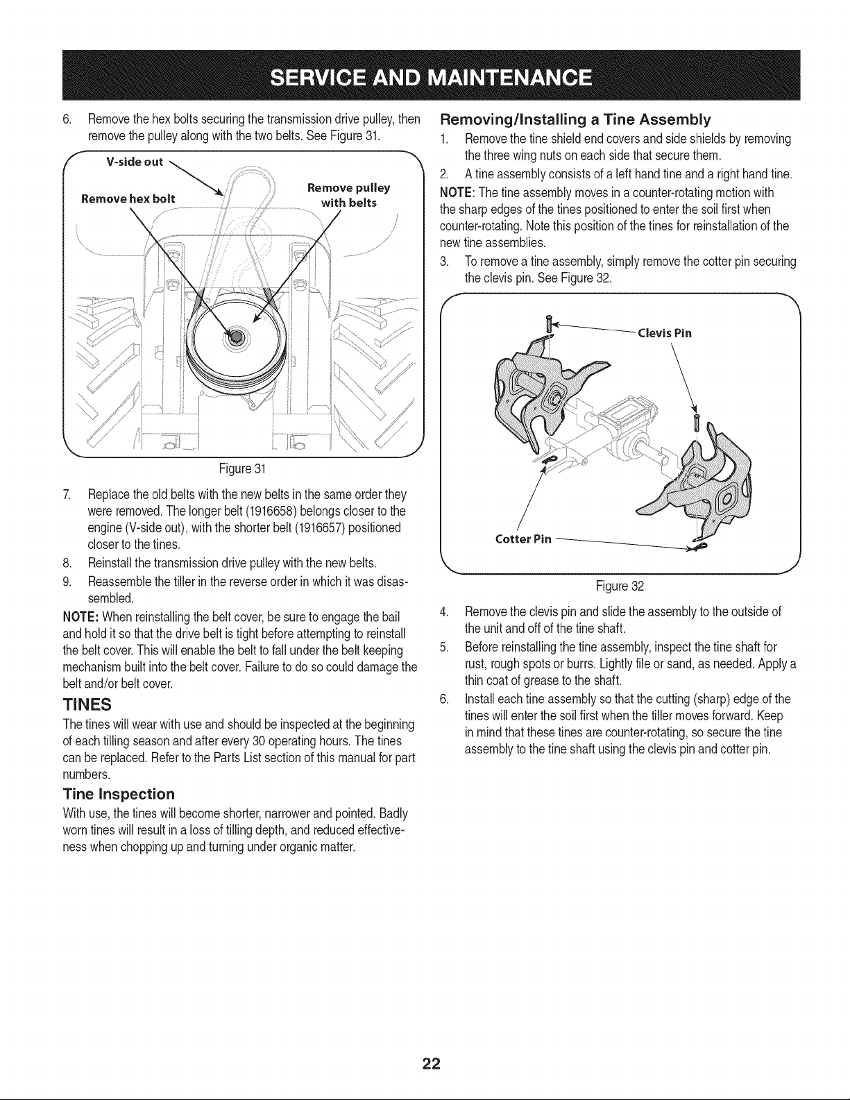
6. Removethehex bolts securingthe transmissiondrivepulley,then
removethe pulleyalongwith the twobelts. See Figure31.
F V-side out
,
Remove pulley
Remove he× bolt with belts
Figure31
7. Replacetheold beltswiththe new beltsin the sameorder they
wereremoved.The longerbelt (1916658)belongscloserto the
engine(V-sideout), withthe shorter belt(1916657)positioned
closerto the tines.
8. Reinstallthe transmissiondrive pulleywith the new belts.
9. Reassemblethe tiller in the reverseorderin whichit wasdisas-
sembled.
NOTE:Whenreinstallingthe beltcover,be sureto engagethe bail
andholdit so thatthe drivebelt is tightbeforeattemptingto reinstall
the beltcover.Thiswill enablethe beltto fall underthe beltkeeping
mechanismbuiltintothe belt cover.Failureto do socould damagethe
beltand/or beltcover.
TINES
Thetines will wearwith useand shouldbe inspectedat the beginning
of eachtilling seasonandafterevery30 operatinghours.Thetines
can be replaced.Refertothe PartsListsectionof thismanualfor part
numbers.
Tine Inspection
Withuse,the tines will becomeshorter,narrowerand pointed.Badly
worntines will resultin a lossof tilling depth,and reducedeffective-
nesswhenchoppingup and turningunderorganicmatter.
Removing/Installing a Tine Assembly
1. Removethe tine shieldendcoversand side shieldsby removing
the threewing nutson eachside that securethem.
2. A fine assemblyconsistsof a left handtine and a righthandfine.
NOTE:The tineassemblymovesinacounter-rotatingmotionwith
the sharpedgesof the tines positionedto enterthe soilfirst when
counter-rotating.Notethispositionof the tinesfor reinstallationof the
newfineassemblies.
To removea fineassembly,simplyremovethe cotterpin securing
the clevispin. See Figure32.
_' Clevis Pin
Cotter Pin
Figure32
4. Removethe clevispin and slidethe assemblyto theoutsideof
the unit andoffof the fine shaft.
5. Beforereinstallingthe tine assembly,inspectthefine shaftfor
rust,roughspotsor burrs.Lightlyfile or sand,as needed.Applya
thin coat of greaseto the shaft.
6. Installeachfine assemblysothatthe cutting(sharp)edgeof the
tineswill enterthe soilfirst whenthe tillermovesforward.Keep
inmindthat these tinesare counter-rotating,so securethefine
assemblyto thefine shaft usingthe clevispinandcotter pin.
22
Neverstoretiller withfuel in tankindoorsor in poorlyventilatedareasI
wherefuel fumesmay reachan open flame,spark,or pilotlightas on
a furnace,waterheater,c othesdryer,orgas app ance. 1
Neverleaveengineunattendedwhileit is running.
PREPARING THE ENGINE
Enginesstored between30and 90daysneedto betreatedwitha
gasolinestabilizerandenginesstoredover90daysneedto bedrained
of fuel to preventdeteriorationandgumfromforminginfuel systemor
on essentialcarburetorparts.Ifthe gasolineinyourenginedeterio-
ratesduringstorage,you mayneedto havethecarburetor,andother
fuel systemcomponents,servicedor replaced.
1. Removeallfuel from tank by runningengineuntilit stopsfrom
lackof fuel.
2. Changethe oil. See ChangeEngineOil in SERVICEAND
MAINTENANCEsection.
3. Removespark plugand pourabouta 1/2ounceof engineoilinto
the cylinder.Replacesparkplugandcrankit slowlyto distribute
oil.
4. Cleandebrisfrom aroundtheengineandthe muffler.Touchup
any damagedpaint,andcoat otherareasthatmay rustwith a light
filmof oil.
5. Storein a clean,dry and wellventilatedareaawayfromany ap-
pliancethat operateswitha flameorpilot light, suchas a furnace,
waterheater,orclothesdryer.Alsoavoidany areawith a spark
producingelectricmotor,or wherepowertoolsare operated.
6. Ifpossible,also avoidstorageareaswithhighhumidity,because
that promotesrust and corrosion.
7. Keeptheenginelevelinstorage.Tiltingcan causefuel or oil
leakage.
PREPARING THE TILLER
Whenthe tillerwon't be usedfor an extendedperiod,prepareit for
storageas follows:
1. Cleanthe tillerand engine.
2. Followthe lubricationrecommendationsand checkfor looseparts
and hardware.
3. Storethe tiller ina clean,dry area.
4. Neverstorethe tillerwith fuel inthe fuel tankinan enclosedarea
wheregas fumescould reachan openflameor spark,or where
ignitionsourcesare present(spaceheaters,hot waterheaters,
furnaces,etc.).
23
Beforeperforminganytyped maintenance/service,disengageall controlsand stoptheengine.Waituntilall
movingpartshavecometo acompletestop.Disconnectsparkplugwireandgroundit againsttheenginetoprevent
unintendedstarting.Alwayswearsafetyglassesduringoperationorwhileperforminganyadjustmentsorrepairs.
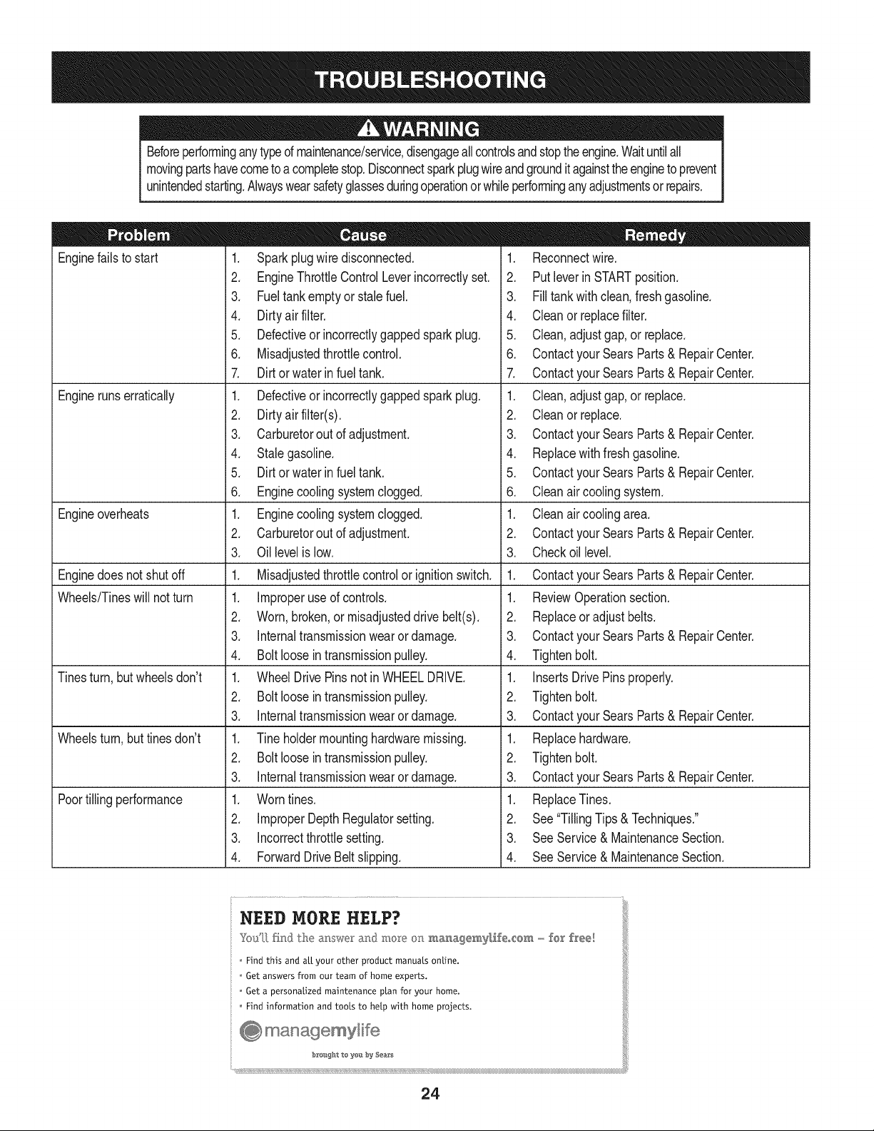
Enginefailsto start
Enginerunserratically
Engineoverheats
Enginedoesnot shut off
Wheels/Tineswill notturn
Tinesturn, butwheelsdon't
Wheelsturn,buttines don't
Poortilling performance
1. Sparkplugwire disconnected.
2. EngineThrottleControlLeverincorrectlyset.
3. Fueltankemptyor stalefuel.
4. Dirtyair filter.
5. Defectiveor incorrectlygappedsparkplug.
6. Misadjustedthrottlecontrol.
7. Dirt or water in fuel tank.
1. Defectiveor incorrectlygappedsparkplug.
2. Dirtyairfilter(s).
3. Carburetorout of adjustment.
4. Stalegasoline.
5. Dirt or water in fuel tank.
6. Enginecoolingsystemclogged.
1. Enginecoolingsystemclogged.
2. Carburetorout of adjustment.
3. Oil levelis low.
1. Misadjustedthrottlecontrolor ignitionswitch.
1. Improperuse of controls.
2. Worn,broken,or misadjusteddrive belt(s).
3. Internaltransmissionwearor damage.
4. Bolt looseintransmissionpulley.
1. WheelDrivePinsnot inWHEELDRIVE.
2. Bolt loosein transmissionpulley.
3. Internaltransmissionwearor damage.
1. Tine holdermountinghardwaremissing.
2. Bolt loosein transmissionpulley.
3. Internaltransmissionwearor damage.
1. Worntines.
2. ImproperDepthRegulatorsetting.
3. incorrectthrottlesetting.
4. ForwardDriveBeltslipping.
1. Reconnectwire.
2. Putleverin STARTposition.
3. Filltank with clean,fresh gasoline.
4. Cleanor replacefilter.
5. Clean, adjustgap,or replace.
6. Contactyour SearsParts& RepairCenter.
7. Contactyour SearsParts& RepairCenter.
1. Clean,adjustgap,or replace.
2. Cleanor replace.
3. Contactyour SearsParts& RepairCenter.
4. Replacewithfresh gasoline.
5. Contactyour SearsParts& RepairCenter.
6. Cleanair coolingsystem.
1. Cleanair coolingarea.
2. Contactyour SearsParts& RepairCenter.
3. Checkoil level.
1. Contactyour SearsParts& RepairCenter.
1. ReviewOperationsection.
2. Replaceor adjustbelts.
3. Contactyour SearsParts& RepairCenter.
4. Tightenbolt.
1. InsertsDrive Pinsproperly.
2. Tightenbolt.
3. Contactyour SearsParts& RepairCenter.
1. Replacehardware.
2. Tightenbolt.
3. Contactyour SearsParts& RepairCenter.
1. ReplaceTines.
2. See"TillingTips & Techniques."
3. SeeService& MaintenanceSection.
4. SeeService& MaintenanceSection.
NEED MORE HELP?
Youq] [h}d the m_swe_ and mo_}_ on ma_agemy[_eo_em - fear f_'ee!
Find this and air your other product manuats ontine.
Get answers from our team of home experts.
Get a personatized maintenance ptan for your home.
Find information and toots to hetp with home projects.
÷ managemylife
_O_ght te yeI:_ by Sea_s
24

25
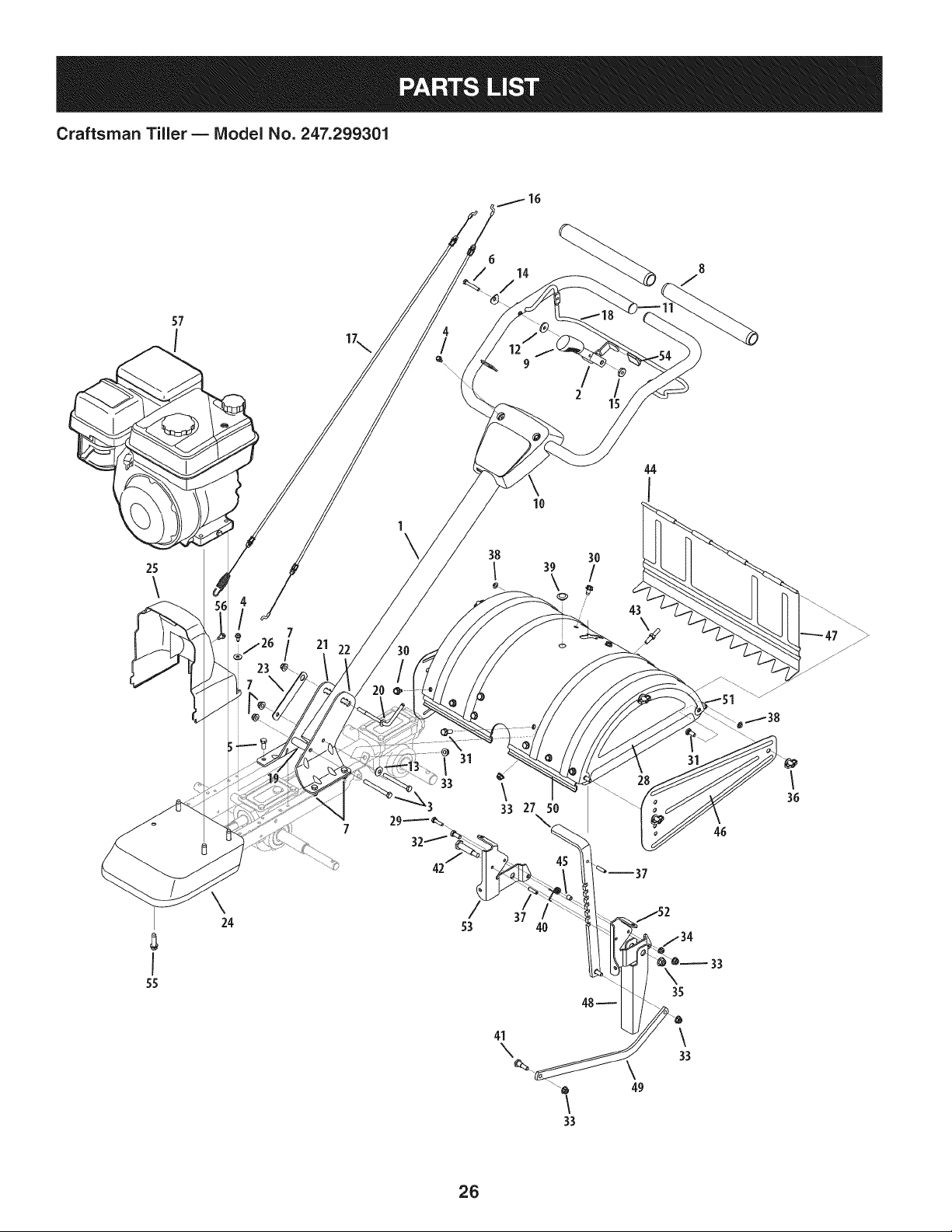
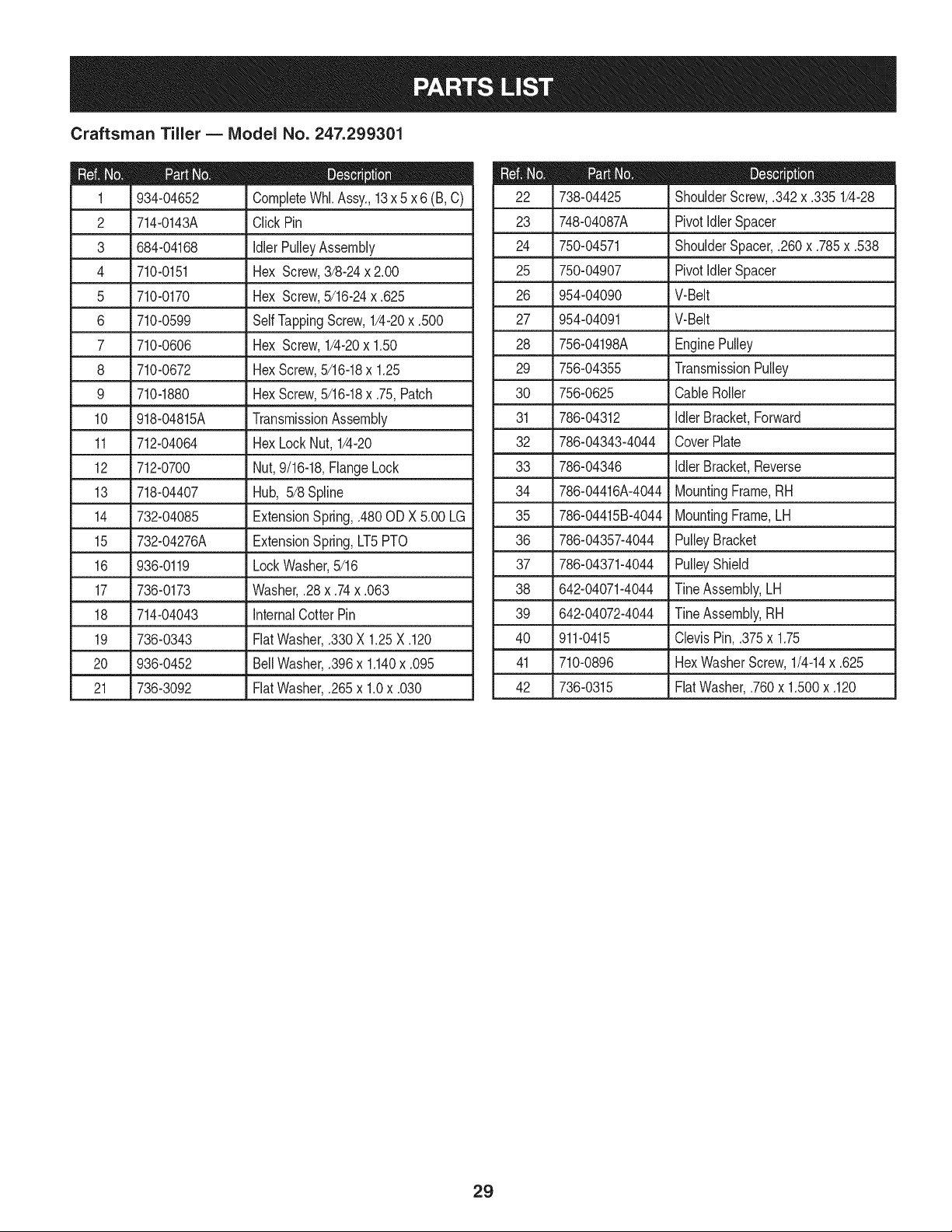
Craftsman Tiller B Model No. 247.299301
8
/
/
2
8
I
55
\
24
7
/
1
\
\
lO
\
33 27 50
37
40
41
\
\
33
49
\
33
33
36
26
Craftsman Tiller B Model No. 247.299301
2
3
4
5
6
7
649-04098A-4044
686-04135-4044
710- 0189
710-0599
710-1238
710-3288
712-04063
Upper Handle Assembly
Reverse Handle Assembly
Hex Screw, 5/16-18 x 3.00
Hex Washer Screw, 1/4-20 x 0.500
Hex Washer Screw, 5/16-18 x .875
Hex Lock Screw, 1/4-20 x 1.62
Flange Lock Nut, 5/16-18
8 720-0278A Foam Grip, .970 x 11.0
9 731-04735 Selector Handle
10 731-06253A Handle Cover, 400
11 735-04105
12 936-0176
13 736-0242
14 936-0451
15 738-0440
End Plug
Flat Washer, .265 x .938 x .120
Bell Washer, .340 x .872 x .060
Saddle Washer, .320 x .93 x .060
Shoulder Spacer, .375 x .165
16 946-04504 Reverse Cable
17 946-04506 Forward Cable
18 747-04789-0637 Bail
19 750-0885A Spacer, .322 x .625 x 2.00
20 786-0340B Handle Adjustment Crank
21 786-04344-4044 RH Handle Bracket
22. 786-04345-4044 LH Handle Bracket
23 786-04346 400 Nut Retainer Bracket
24 786-04360-4044 Front Bumper
25 731-06529 Belt Cover
26 736-0173 Flat Washer, .28 x .74 x .063
27 786-04356-4044 Depth Adjustment Bracket
28 686-0044B-4044 End Cover Assembly
29 710-0597 Hex Screw, 1/4-20 x 1.00
710-0604A Hex Washer Screw, 5/16-18 x 0.625
31 710-1238 Hex Washer Screw, 5/16-18 x .875
32 710-3008 Hex Screw, 5/16-18 x .75
33 712-04063 Flange Lock Nut, 5/16-18
34 712-04064 Flange Lock Nut, 1/4-20
35 712-04065 Flange Lock Nut, 3/8-16
36 712-0421 Wing Nut w/Bell Washer, 5/16-18
37 715-0108 Spring Pin, 1/4 x 1.00
38 926-0106 Cap Speed Nut, 1/4
39 731-05512 Deck Hole Plug
40 732-04320 Torsion Spring
41 738-04320 Shoulder Screw, 5/16-18 x .405 x .345
42 938-0533 Shoulder Screw, .498 x 1.635
43 938-0849 Hex Screw, 5/16-18 x .75
44 747-0432 Tiller Flap Rod
45 750-05349 Round Spacer, .370 x .260 x .410
46 786-0090A-4044 Side Shield
47 786-0113A-4044 Rear Tine Shield
48 786-04092-4044 Stop Reverse Arm
49 786-04104-4044 Depth Drag Bar
50 786-04352A-4044 Tine Shield Mount Bracket
51 786-04355A-4044 Tine Shield
52 786-04363-4044 LH Tail Bracket
53 786-04364-4044 RH Tail Bracket
54 720-04173 Reverse Handle Grip
55 710-0502A Hex Washer Screw, 3/8-16 x 1.250
56 710-0896 Hex Washer Screw, 3/8-16 x 1.250
57 952Z170-TU Replacement Engine
27
Craftsman Tiller B Model No. 247.299301
33
7
34
32
12
29
19
\
15
38
18
28
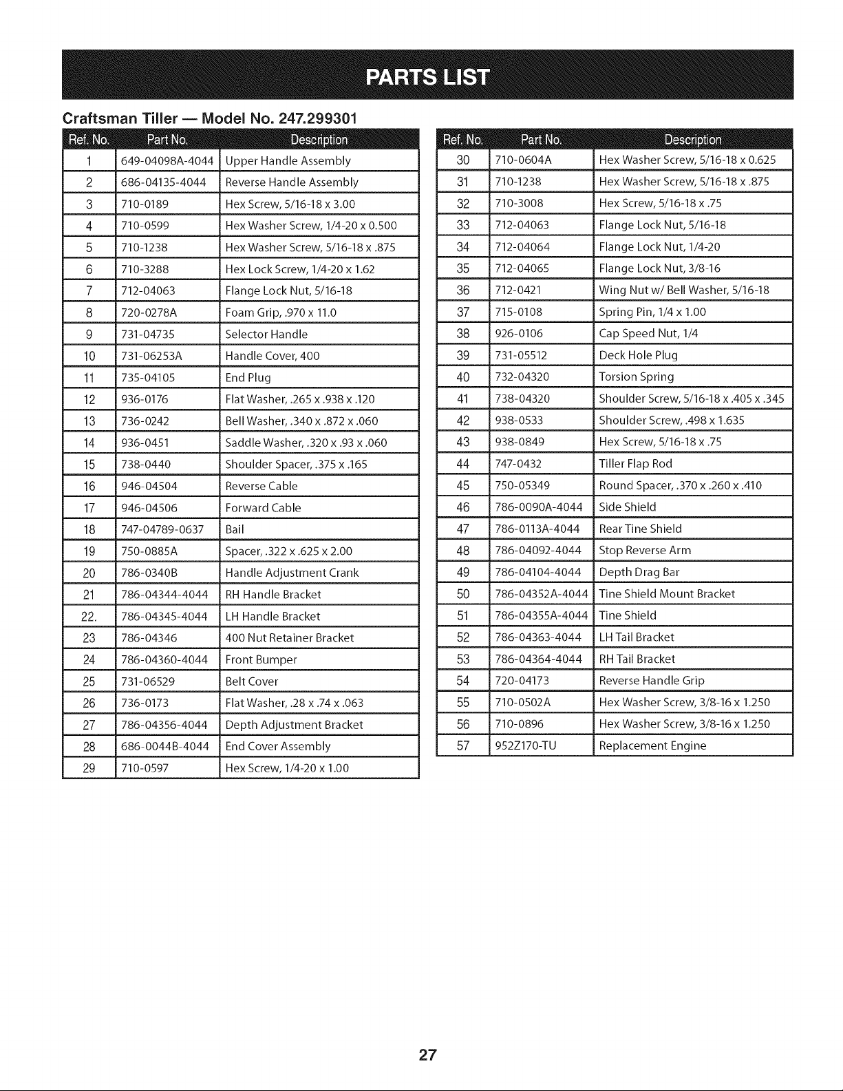
Craftsman Tiller B IViodel No. 247.299301
934-04652 CompleteWhl.Assy.,13x 5 x 6 (B,C)
2 714-0143A Click Pin
3 684-04168 Idler PulleyAssembly
4 710-0151 Hex Screw,3/8-24x 2.00 25
5 710-0170 Hex Screw,5/16-24x .625 26
6 710-0599 SelfTappingScrew,1/4-20x .500 27
7 710-0606 Hex Screw,1/4-20x 1.50 28
8 710-0672 HexScrew,5/16-18x 1.25 29
9 710-1880 HexScrew,5/16-18x .75,Patch 30
10 918-04815A TransmissionAssembly 31
11 712-04064 HexLock Nut, 1/4-20 32
12 712-0700 Nut,9/16-18,FlangeLock 33
13 718-04407 Hub, 5/8 Spline 34
14 732-04085 ExtensionSpring,.480ODX 5.00 LG 35
15 732-04276A ExtensionSpring,LT5PTO 36
16 936-0119 LockWasher,5/16 37
17 736-0173 Washer,.28x .74x .063 38
18 714-04043 InternalCotterPin 39
19 736-0343 FlatWasher,.330X 1.25X .120 40
20 936-0452 Bell Washer,.396x 1.140x .095
21 736-3092 Flat Washer,.265x 1.0x .030
738-04425 ShoulderScrew,.342x .335 1/4-28
23 748-04087A PivotIdlerSpacer
24 750-04571 ShoulderSpacer,.260x .785x .538
750-04907 PivotIdlerSpacer
954-04090 V-Belt
954-04091 V-Belt
756-04198A EnginePulley
756-04355 TransmissionPulley
756-0625 CableRoller
786-04312 IdlerBracket,Forward
786-04343-4044 CoverPlate
786-04346
786-04416A-4044
786-04415B-4044
786-04357-4044
786-04371-4044
642-04071-4044
642-04072-4044
911-0415
IdlerBracket,Reverse
MountingFrame,RH
MountingFrame,LH
PulleyBracket
PulleyShield
Tine Assembly,LH
Tine Assembly,RH
ClevisPin,.375x 1.75
41 710-0896 HexWasherScrew,1/4-14x .625
42 736-0315 FlatWasher,.760x 1.500x .120
29

Craftsman Tiller B Model No. 247.299301
12
2
i iT
18
6
\
4
19
2o \
17 18
14
21
7
11
1o
6
14
7
21
\
\
3O
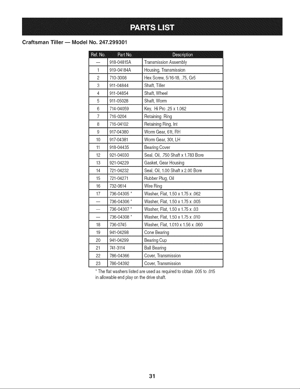
Craftsman Tiller B IViodel No. 247.299301
D = t
918-04815A TransmissionAssembly
1 919-04184A Housing,Transmission
2 710-3008 HexScrew,5/16-18,.75,Gr5
3 911-04844 Shaft,Tiller
4 911-04854 Shaft,Wheel
5 911-05028 Shaft,Worm
6 714-04059 Key, Hi Pro .25x 1.062
7 716-0204 Retaining Ring
8 716-04102 RetainingRing,Int
9 917-04380 WormGear,61t,RH
10 917-04381 WormGear,30t,LH
11 918-04435 BearingCover
12 921-04030 Seal,Oil, .750Shaftx 1.783Bore
13 921-04229 Gasket,GearHousing
14 721-04232 Seal,Oil, 1.00Shaftx 2.00 Bore
15 721-04271 RubberPlug,Oil
16 732-0614 Wire Ring
17 736-04305*
-- 736-04306"
-- 736-04307"
-- 736-04308"
18 736-0745
19 941-04298
20 941-04299
21 741-3114
Washer,Flat,1.50x 1.75x .062
Washer,Flat,1.50x 1.75x .005
Washer,Flat,1.50x 1.75x .03
Washer,Flat,1.50x 1.75x .010
Washer,Flat,1.010x 1.56x .060
Cone Bearing
BearingCup
Ball Bearing
22 786-04366 Cover,Transmission
23 786-04392 Cover,Transmission
* Theflat washerslistedareusedas requiredto obtain.005to .015
inallowableendplayon the driveshaft.
31
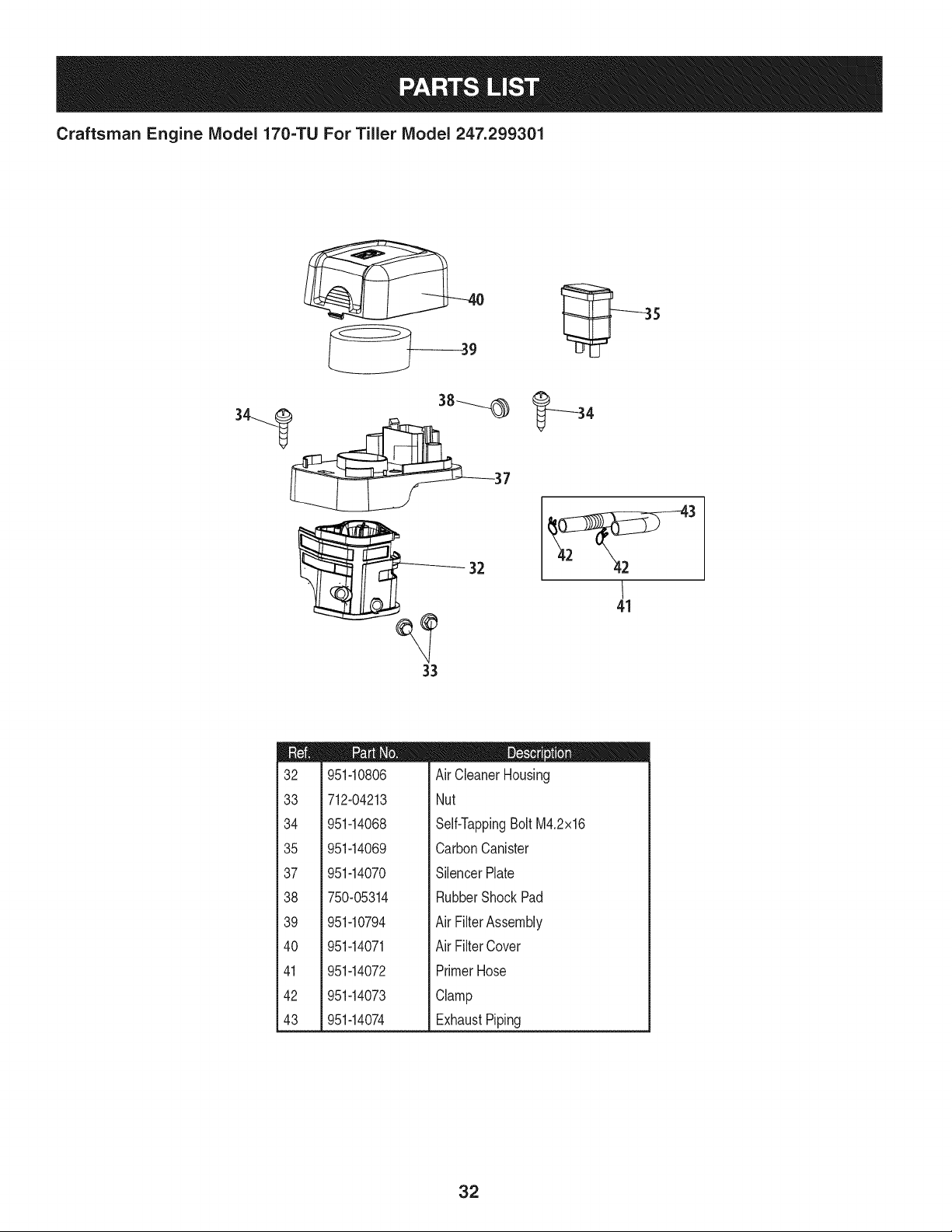
Craftsman Engine Model 170=TU For Tiller Model 247.299301
32
33
41
m
!
t
i32
!
t
133
i
i
i
134
i
i
i
i35
!
t
137
i
i
i
i38
!
!
t
139
i
i
140
i
i
i
i41
!
t
i
142
i
i43
951-10806
712-04213
951-14068
951-14069
951-14070
750-05314
D = 0
AirCleanerHousing
Nut
Self-TappingBoltM4.2x16
CarbonCanister
SilencerPlate
RubberShockPad
951-10794
951-14071
951-14072
951-14073
951-14074
AirFilterAssembly
AirFilterCover
PrimerHose
Clamp
ExhaustPiping
32
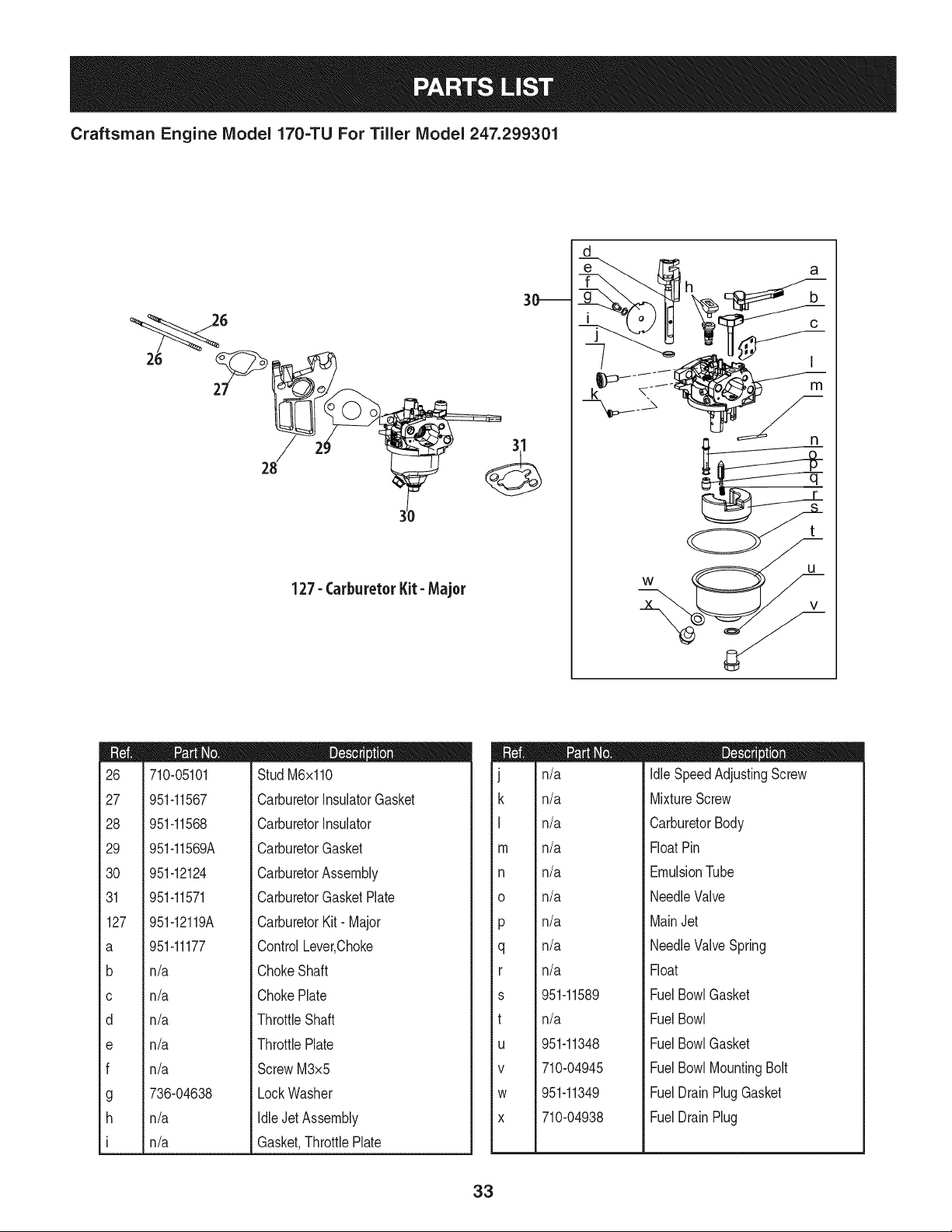
Craftsman Engine IViodel 170=TU For Tiller IViodel 247.299301
3_
127- Carburetor Kit- Major
d
I
m
n
m
26
27
28
29
30
31
127
a
b
C
d
e
f
g
h
I
710-05101
951-11567
951-11568
951-11569A
951-12124
951-11571
951-12119A
D = O O
Stud M6x110
CarburetorInsulatorGasket
CarburetorInsulator
CarburetorGasket
CarburetorAssembly
CarburetorGasketPlate
CarburetorKit- Major
951-11177
n/a
n/a
n/a
n/a
n/a
736-04638
n/a
n/a
ControlLever,Choke
ChokeShaft
ChokePlate
ThrottleShaft
ThrottlePlate
ScrewM3x5
LockWasher
IdleJet Assembly
Gasket,ThrottlePlate
m
J
k
I
m
n
O
P
q
r
s
t
U
V
W
X
n/a
n/a
n/a
n/a
n/a
n/a
n/a
n/a
n/a
951-11589
n/a
951-11348
710-04945
951-11349
710-04938
D = O O
IdleSpeedAdjustingScrew
MixtureScrew
CarburetorBody
FloatPin
EmulsionTube
NeedleValve
MainJet
NeedleValveSpring
Float
FuelBowlGasket
FuelBowl
FuelBowlGasket
FuelBowlMountingBolt
FuelDrainPlugGasket
FuelDrainPlug
33
Craftsman Engine IViodel 170=TU For Tiller IViodel 247.299301
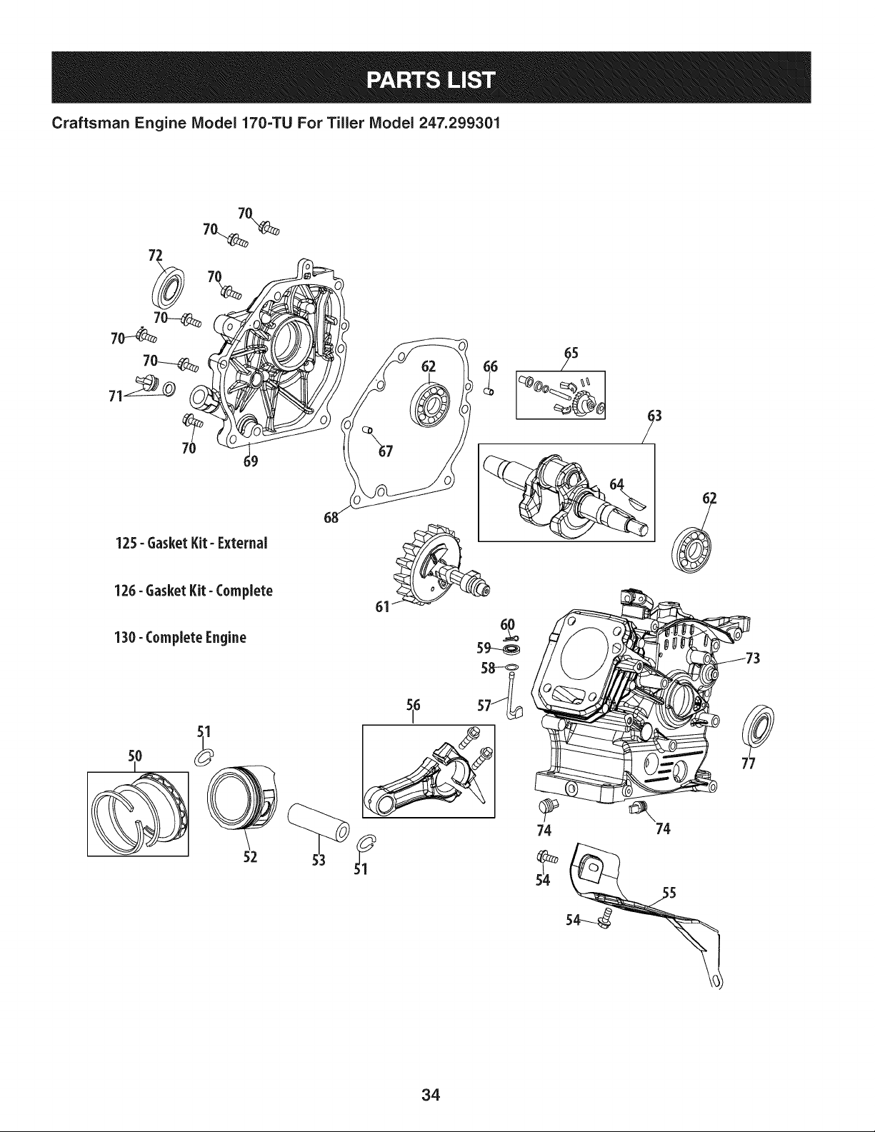
125- Gasket Kit- External
125- Gasket Kit- Complete
130- Complete Engine
510
52
3
74 74
34
Craftsman Engine IViodel 170=TU For Tiller IViodel 247.299301
m
5O
51
52
53
54
55
56
57
58
59
6O
61
62
63
64
65
66
67
68
69
70
71
72
73
74
77
125
126
130
951-12111
951-11632
951-12007
951-11633
710-04915
951-11113
951-11573
951-11356
736-04461
951-11574
714-04074
951-11575
951-11369
951-12160
951-10307
951-11576
715-04092
715-04089
951-11371
951-12125
710-04932
951-11283
951-11578
951-12551
951-12514
951-12126
951-12573
951-12572
952Z170_U
m = O O
PistonRingSet
PistonPinSnapRing
Piston
PistonPin
Bolt M6x12
Air Shield
ConnectingRodAssembly
GovernorArm Shaft
Washer5.2xl.9
GovernorSeal
CotterPin
CamshaftAssy.
RadialBall Bearing,6205
CrankshaftAssembly
WoodruffKey
GovernorGear/ShaftAssembly
DowelPin7x14
DowelPin9x14
CrankcaseCoverGasket
CoverComp,LeftCrankcase
Bolt M8x32
OilPlug
OilSeal,25x41.25x6
ShortBlock
(Incl.6,22,27,28,44,46,47,
50-53,56-70,72-75)
OilDrain Plug
OilSeal25x41.25x6
GasketKit- External
(Incl.6,22,27-29,31)
GasketKit- Complete
(Incl.6,22,27-29,31,44,
58,59,68,72,75)
CompleteEngine
35
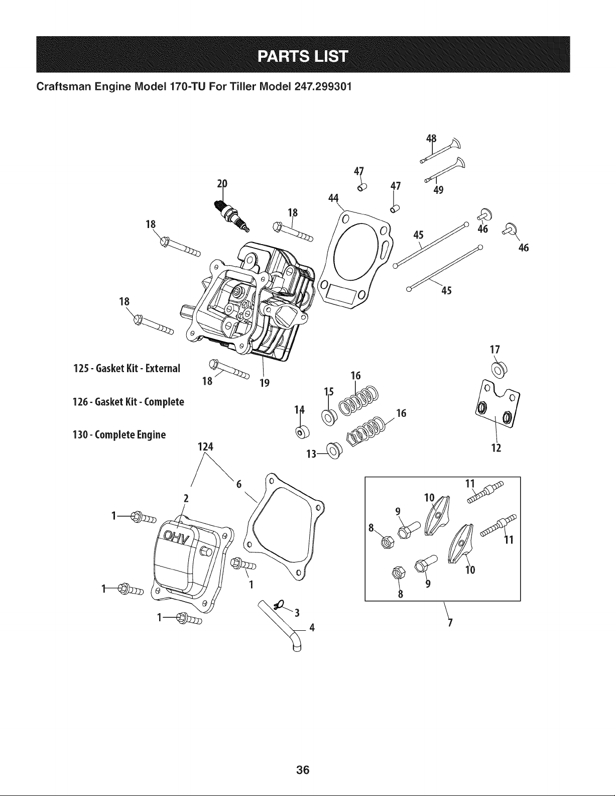
Craftsman Engine IViodel 170=TU For Tiller IViodel 247.299301
18
124
\
7
36
Craftsman Engine IViodel 170=TU For Tiller IViodel 247.299301
m
1
2
3
4
6
7
8
9
10
11
12
13
14
15
16
17
18
19
710-04968
951-11054
726-04101
731-07059
D = B 0
BoltM6x16
ValveCover
BreatherHoseClamp
ExhaustPiping
951-11565
951-11892
751-11124
751-11123
951-11893
710-04902
ValveCoverGasket
RockerArmAssembly
Nut,Pivot Locking
AdjustingNut,Valve
RockerArm
Bolt,Pivot
951-11895
951-12000
951-12002
951-12003
951-12004
951-11894
710-04933
951-10819
PushRodGuide
Retainer,In.ValveSpring
Adjuster,ExhValve
Retainer,Ex.ValveSpring
ValveSpring
IntakeValveSeal
BoltM8x55
CylinderHeadServiceKit
m
2O
44
45
46
47
48
49
124
125
126
130
951-10722A
951-10292
951-11572
951-10648
951-11899
715-04108
951-10647A
951-10647A
951-11063A
951-12573
951-12572
952Z170-TU
D = " O O
Incl.4,15,16,38)
CylinderHeadAssembly
(Incl.6,8-17,19,22,28,
29,44,48,49)
SparkPlug/F6Rtc
Gasket,CylinderHead
PushRodKit
Tappet
DowelPin10x16
ValveKit
ValveKit
ValveCoverKit
GasketKit- External
(Incl.6,22,27-29,31)
GasketKit- Complete
(Incl.6,22,27-29,31,44,
58,59,68,72,75)
CompleteEngine
37
Craftsman Engine Model 170=TUFor Tiller Model 247.299301
_122
m
75
76
78
79
8O
81
82
83
84
86
87
88
89
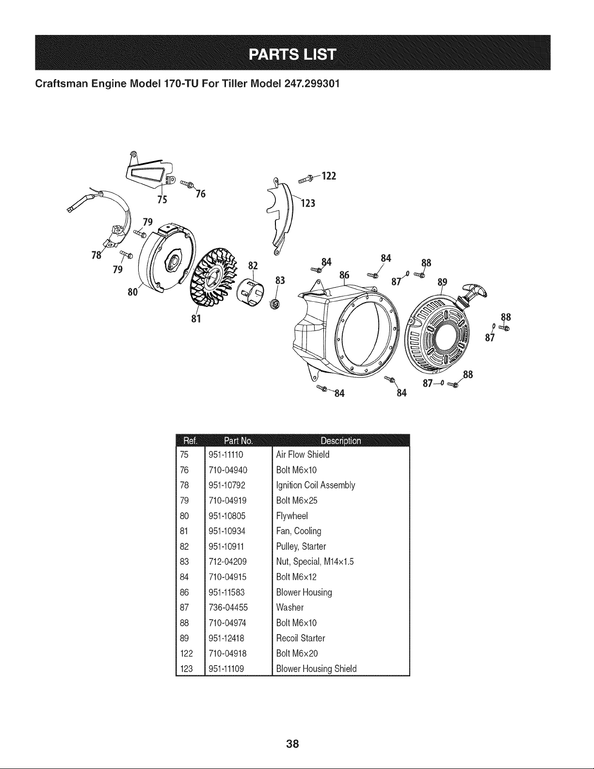
122
123
951-11110
710-04940
951-10792
710-04919
951-10805
951-10934
951-10911
712-04209
710-04915
951-11583
736-04455
710-04974
951-12418
710-04918
951-11109
D = " O O
Air FlowShield
BoltM6xlO
IgnitionCoil Assembly
BoltM6x25
Flywheel
Fan,Cooling
Pulley,Starter
Nut,Special,M14x1.5
BoltM6x12
BlowerHousing
Washer
BoltM6xlO
RecoilStarter
BoltM6x20
BlowerHousingShield
38
Craftsman Engine IViodel 170=TU For Tiller IViodel 247.299301
14
9_ 93
98
_111_107
11oJ
106--_ ¢05
los
lO_ 11_
_--119
12o
_112
_114
m
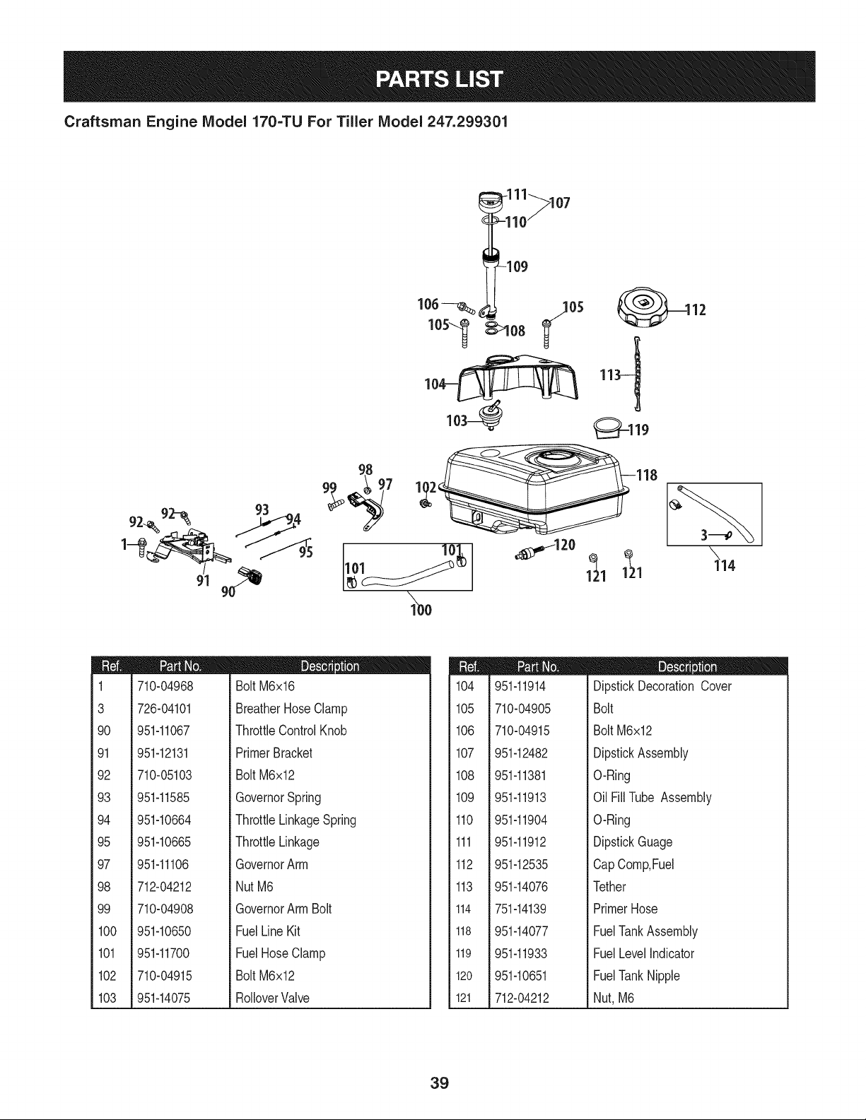
1
3
90
91
92
93
94
95
97
98
99
100
101
102
103
710-04968
726-04101
951-11067
951-12131
710-05103
951-11585
951-10664
951-10665
951-11106
712-04212
710-04908
951-10650
951-11700
710-04915
951-14075
m = B II
BoltM6x16
BreatherHose Clamp
ThrottleControlKnob
PrimerBracket
BoltM6x12
GovernorSpring
ThrottleLinkageSpring
ThrottleLinkage
GovernorArm
NutM6
GovernorArmBolt
FuelLine Kit
FuelHoseClamp
BoltM6x12
RolloverValve
104
105
106
107
108
109
110
111
112
113
114
118
119
120
121
951-11914
710-04905
710-04915
951-12482
951-11381
951-11913
951-11904
951-11912
951-12535
951-14076
751-14139
951-14077
951-11933
951-10651
712-04212
D = I! O
DipstickDecorationCover
Bolt
Bolt M6x12
DipstickAssembly
O-Ring
Oil FillTube Assembly
O-Ring
DipstickGuage
CapComp,Fuel
Tether
PrimerHose
FuelTankAssembly
FuelLevelIndicator
FuelTankNipple
Nut, M6
39
Craftsman Engine IViodel 170-TU For Tiller IViodel 247.299301
m
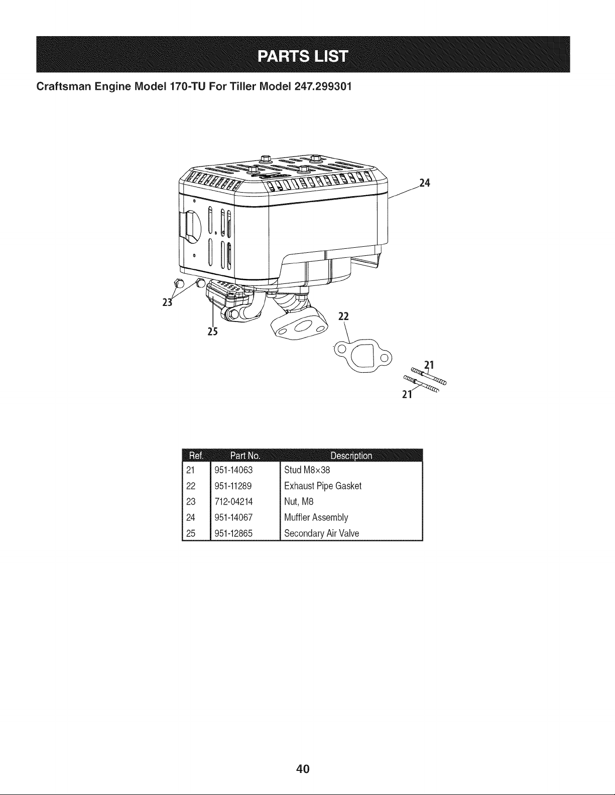
21
22
23
24
25
951-14063
951-11289
712-04214
951-14067
951-12865
D = = O O
StudM8x38
ExhaustPipeGasket
Nut,M8
MufflerAssembly
SecondaryAirValve
4O
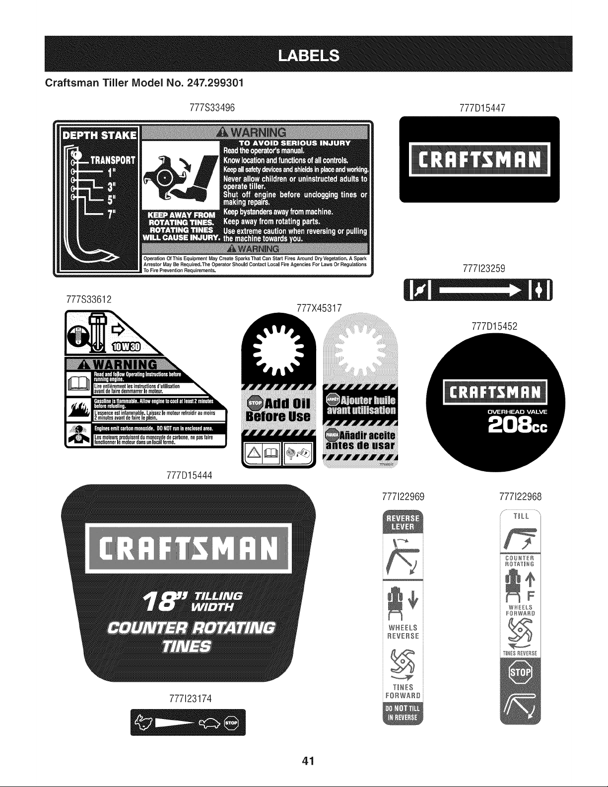
Craftsman Tiler IViodel No. 247.299301
777S33496 777D15447
777S33612
777X45317
777123259
777D15452
777D15444
777i22969 777122968
777123174
WHEELS
REVERSE
YINES
FORWARDi
41
(Thispageapplicableinthe U.S.A.and Canadaonly.)
Sears Brands Management Corporation (Sears), the California Air Resources Board (CARD)
and the United States Environmental Protection Agency (U.S. EPA)
Emission Control System Warranty Statement (Owner's Defect Warranty Rights and Obligations)
EMISSIONCONTROLWARRANTYCOVERAGEISAPPLICABLETO CERTI-
FIEDENGINESPURCHASEDIN CALIFORNIAIN1995ANDTHEREAF-
TER,WHICHARE USEDINCALIFORNIA,ANDTOCERTIFIEDMODEL
California and United States Emission
The CaliforniaAir ResourcesBoard(CARD),U.S.EPAand Searsare pleased
to explainthe EmissionControlSystemWarrantyon your modelyear2000and
latersmalloff-roadengine(SORE).InCalifornia,newsmall off-roadengines
mustbe designed,builtand equippedto meettheState'sstringentanti-smog
standards.Elsewherein the UnitedStates, newnon-road,spark-ignition
enginescertifiedfor modelyear 1997and latermustmeetsimilarstandardsset
forth bythe U.S.EPA.Searsmustwarranttheemissioncontrol systemon your
YEAR 1997AND LATERENGINESWHICHARE PURCHASEDAND USED
ELSEWHEREIN THE UNITEDSTATES(ANDAFTERJANUARY1,2001 IN
CANADA).
Control Defects Warranty Statement
enginefor theperiodsoftime listedbelow,providedtherehas been noabuse,
neglector impropermaintenanceof your smalloff-roadengine.Youremis-
sion controlsystemincludespartssuch as thecarburetor,air cleaner,ignition
system,mufflerand catalyticconverter.Also includedmaybe connectorsand
otheremissionrelatedassemblies.Wherea warrantableconditionexists,Sears
will repairyour smalloff-roadengineat no costto you includingdiagnosis,parts
and labor.
Sears Emission Control Defects Warranty Coverage
Smalloff-roadenginesarewarrantedrelativeto emissioncontrol partsdefects
fora period of one year,subjectto provisionsset forthbelow.Ifany covered
Owner's Warranty
Asthe smalloff-roadengine owner,you are responsiblefor theperformanceof
therequiredmaintenancelistedin yourOperatingand MaintenanceInstruc-
tions.Searsrecommendsthatyou retain all yourreceiptscoveringmaintenance
on yoursmalloff-roadengine,but Sears cannotdenywarrantysolelyfor the
lackof receiptsor for yourfailureto ensurethe performanceof all scheduled
maintenance.As the smalloff-roadengineowner,you shouldhoweverbe
awarethat Searsmay denyyou warrantycoverageifyour smalloff-roadengine
ora part hasfaileddueto abuse,neglect,impropermaintenanceor unap-
parton yourengineis defective,the part will be repairedorreplacedbySears.
Responsibilities
provedmodifications.Youare responsiblefor presentingyour smalloff-road
engineto an AuthorizedSearsServiceDealeras soonas a problemexists.The
undisputedwarrantyrepairsshouldbe completedina reasonableamountof
time,notto exceed30 days.Ifyou haveany questionsregardingyourwarranty
rightsand responsibilities,youshouldcontacta SearsService Representative
at 1-800-469-4663.The emissionwarrantyis a defectswarranty.Defectsare
judgedon normalengineperformance.The warrantyis notrelatedto an in-use
emissiontest.
Sears Emission Control Defects Warranty Provisions
ThefollowingarespecificprovisionsrelativetoyourEmissionControlDefectsWarrantyCoverage.Itisin additiontotheSearsenginewarrantyfornon-regulated
enginesfoundin theOperatingand MaintenanceInstructions.
1. WarrantedParts
Coverageunderthis warrantyextendsonly to the parts listedbelow (the
emissioncontrolsystemsparts)to the extentthese partswere presenton
theengine purchased.
a. FuelMeteringSystem
• Cold start enrichmentsystem
• Carburetorand internalparts
• FuelPump
b. Air lnduction System
• Air cleaner
• Intakemanifold
c. IgnitionSystem
• Spark plug(s)
• Magnetoignitionsystem
d. CatalystSystem
• Catalyticconverter
• Exhaustmanifold
• Air injectionsystemor pulsevalve
e. MiscellaneousItemsUsedin AboveSystems
• Vacuum,temperature,position,time sensitivevalves
andswitches
• Connectorsandassemblies
2. Lengthof Coverage
Searswarrantsto the initialownerand eachsubsequentpurchaserthat
theWarrantedPartsshallbe free from defects in materialsandworkman-
shipwhich causedthefailure of the WarrantedPartsfor a period of one
yearfrom the datethe engineis deliveredto a retailpurchaser.
3. NoCharge
Repairor replacementof anyWarrantedPartwill beperformedat no
chargeto the owner,includingdiagnosticlabor whichleadsto the
determinationthata WarrantedPartis defective,if the diagnosticwork is
performedat an AuthorizedSears ServiceDealer.For emissionswarranty
servicecontact yournearestAuthorizedSears ServiceDealeras listed in
the "YellowPages"under"Engines,Gasoline,""GasolineEngines,""Lawn
Mowers,"orsimilarcategory.
4. Claimsand CoverageExclusions
Warrantyclaimsshall be filed in accordancewiththe provisionsof the
Sears EngineWarrantyPolicy.Warrantycoverageshall be excludedfor
failuresof WarrantedPartswhichare notoriginal Sears partsor because
of abuse,neglector impropermaintenanceas setforth inthe Sears
EngineWarrantyPolicy.Sears is notliableto coverfailuresof Warranted
Partscausedby theuse of add-on, non-original,or modifiedparts.
5. Maintenance
Any WarrantedPart whichis not scheduledfor replacementas required
maintenanceor whichis scheduledonly for regularinspectionto the effect
of "repairor replaceas necessary"shallbe warrantedas to defectsfor the
warrantyperiod.Any WarrantedPartwhich is scheduledfor replacement
as requiredmaintenanceshallbe warrantedas to defectsonly forthe
periodof time upto the firstscheduledreplacementfor that part. Any
replacementpart that is equivalentin performanceand durabilitymay
be usedin the performanceof any maintenanceor repairs.The owneris
responsibleforthe performanceof all requiredmaintenance,as definedin
the SearsOperatingand MaintenanceInstructions.
6. ConsequentialCoverage
Coveragehereundershallextend to the failure of any engine components
caused bythe failureof any WarrantedPartstill underwarranty.
Inthe USAandCanada,a 24 hour hot line, 1-800-469-4663,has a menu of pre-recordedmessagesofferingyou enginemaintenanceinformation.
GDOC-100188Rev.B
42
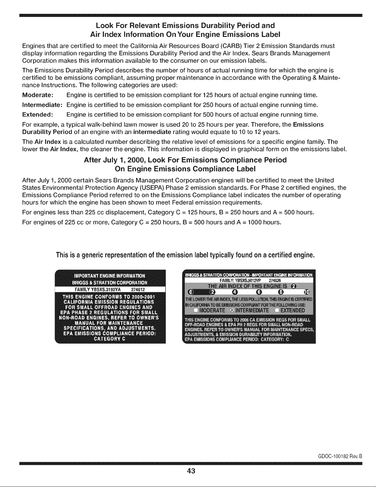
Look For Relevant Emissions Durability Period and
Air index information On Your Engine Emissions Label
Engines that are certified to meet the California Air Resources Board (CARB) Tier 2 Emission Standards must
display information regarding the Emissions Durability Period and the Air Index. Sears Brands Management
Corporation makes this information available to the consumer on our emission labels.
The Emissions Durability Period describes the number of hours of actual running time for which the engine is
certified to be emissions compliant, assuming proper maintenance in accordance with the Operating & Mainte-
nance Instructions. The following categories are used:
Moderate: Engine is certified to be emission compliant for 125 hours of actual engine running time.
Intermediate: Engine is certified to be emission compliant for 250 hours of actual engine running time.
Extended: Engine is certified to be emission compliant for 500 hours of actual engine running time.
For example, a typical walk-behind lawn mower is used 20 to 25 hours per year. Therefore, the Emissions
Durability Period of an engine with an intermediate rating would equate to 10 to 12 years.
The Air index is a calculated number describing the relative level of emissions for a specific engine family. The
lower the Air Index, the cleaner the engine. This information is displayed in graphical form on the emissions label.
After July 1,2000, Look For Emissions Compliance Period
On Engine Emissions Compliance Label
After July 1, 2000 certain Sears Brands Management Corporation engines will be certified to meet the United
States Environmental Protection Agency (USEPA) Phase 2 emission standards. For Phase 2 certified engines, the
Emissions Compliance Period referred to on the Emissions Compliance label indicates the number of operating
hours for which the engine has been shown to meet Federal emission requirements.
For engines less than 225 cc displacement, Category C = 125 hours, B = 250 hours and A = 500 hours.
For engines of 225 cc or more, Category C = 250 hours, B = 500 hours and A = 1000 hours.
This is a generic representation of the emission label typically found on a certified engine.
FAMILYYBSXS.3192VA 274812
GDOC-100182Rev.B
43
Congratulations on making a smart purchase. Your new Craftsman® product is designed and
manufactured for years of dependable operation. But like all products, it may require repair
from time to time. That's when having a Repair Protection Agreement can save you money and
aggravation.
Here's what the Repair Protection Agreement* includes:
[] Expert service by our 10,000 professional repair specialists
[] Unlimited service and no charge for parts and labor on all covered repairs
[] Product replacement up to $1500 if your covered product can't be fixed
[] Discount of 25% from regular price of service and related installed parts not covered by the
agreement; also, 25% off regular price of preventive maintenance check
[] Fast help by phone - we call it Rapid Resolution - phone support from a Sears representative.
Think of us as a "talking owner's manual."
Once you purchase the Repair Protection Agreement, a simple phone call is all that it takes for you
to schedule service. You can call anytime day or night, or schedule a service appointment online.
The Repair Protection Agreement is a risk-free purchase. If you cancel for any reason during the
product warranty period, we will provide a full refund. Or, a prorated refund anytime after the
product warranty period expires. Purchase your Repair Protection Agreement today!
Some limitations and exclusions apply. For prices and additional information in the U.S.A.
call 1=800=827=6655.
*Coverage in Canada varies on some items. For full details call Sears Canada at 1=800=361=
6665.
Sears Installation Service
For Sears professional installation of home appliances, garage door openers, water heaters, and
other major home items, in the U.S.A. or Canada call 1=800=4=MY=HOME®.
44
Declaraci6n de garantia ........................ Pb,gina 45
Medidas importantes de seguridad ..... Pb,ginas 46-49
Armado ................................................. Pb,ginas 50-53
Funcionamiento .................................... Pb,ginas 54-59
Servicio y Mantenimiento ..................... P_.ginas 60-65
Almacenamiento fuera de temporada.. Pb,gina 66
Soluci6n de problemas ......................... P_,gina 67
Acuerdo de protecci6n para reparaciones Pb,gina 71
NQmero de servicio ............................... Cubierta posterior
CRAFTSMAN DOS AltOS DE GARANTJA
Durantedos a_osdesdela fechade compra,esteproductoestAgarantizadocontracualquierdefectode materialeso manodeobra. Un
productodefectuosorecibir_la reparaci6no sustituci6ngratuitasi la reparaci6nnoest_disponible.
Paradetalles sobre la garantia de coberturaparaobtener reparaci6ngratuita o reemplazo,visite el sitio web: www.craftsman.com
Esta garantias61ocubre defectos en rnateriaiesy mano de obra. Cobertura de la garantiano ineiuye:
• Bienesfungiblesque puedendesgastarsecon el usonormalenel periodode garantia,comolas cuchillas,dientes,o cinturones.
• DaSosenel productoresultantede los intentosdel usuariode modificaci6ndel productoo la reparaci6no causadosporaccesoriosde
productos.
• Las reparacionesnecesariasdebidoa un accidenteo falla paraoperaro mantenerel productoseg0nlas instruccionessuministradas.
• Mantenimientopreventivoo reparacionesnecesariasdebido a la mezclade combustibleinadecuado,eJcombustiblecontaminadoo viciado.
Estagaranfiaseranulasi el productoes utilizadoalgunavez, mientrasque la prestaci6nde servicioscomercialo si se alquilaa otra persona.
Estagaranfiale otorgaderechoslegalesespecificos,y ustedtambi_npuedetenerotrosderechosquevariandeestadoa estado.
Sears Brands Management Corporation, Hoffman Estates, IL 60179
Seriedel motor: 208cc
Tipode aceite del motor: 10W30
Capacidadde aceitedel motor: 20onzas
Combustible: GasoJinasin plomo
Bujia: F6RTC
Separaci6nde las bujias: .030"
NSmerode modelo ..........................................................
NSmerode serie ..............................................................
Fechade compra .............................................................
Registreel n0merodemodelo,nQmerode serie
y fechade compram_sarriba
@Sears Brands,LLC 45
Lapresenciadeestesimboloindicaquesetratadeinstruccionesde
seguridadimportantesquesedebenrespetarparaevitarponerenpeligro
suseguridadpersonaly/omaterialyladeotraspersonas.Leaycumpla
todaslasinstruccionesdeestemanualantesdeintentaroperaresta
m&quina.Sinorespetaestasinstruccionespuedeprovocarlesiones
personales.Cuandoveaestesimbolo,ipresteatenci6nalaadvertencia!
Estam&quinaest&diseSadaparaserutilizadarespetandolasnormas
deseguridadcontenidasenestemanual.AIigualqueconcualquiertipo
deequipomotorizado,undescuidooerrorporpartedeloperadorpuede
producirlesionesgraves.Estam_quinaescapazdeamputardedos,
manosypiesydearrojarresiduos.Denorespetarlasinstruccionesde
seguridadsiguientessepuedenproducirlesionesgravesolamuerte.
PROPOSICION 65 DE CALiFORNiA
Elescapedel motorde este producto,algunosde sus componentesy
algunoscomponentesdel vehiculocontieneno liberansustanciasquimicas
que el estadode Californiaconsideraque puedenproducircancer,
defectosde nacimientou otrosproblemasreproductivos.Los homes de la
bateriay los accesoriosalines contienenplomoy compuestosde plomo,
sustanciasquimicasque segQnIo establecidopor el Estadode California
causanc&ncery daSosen el sistemareproductivo.L&veselas manos
despuesde estar en contactocon estos componentes.
Su responsabilidad--Lirnite el uso deestarn_.quinarnotorizada
alas personasque lean,cornprendany curnplanlas advertenciase
instruccionesqueaparecenenestemanualyen la rn_.quina.
i6UARI)E ESTASINSTRUCCIONES!
CAPACITACION
• Lea,cornprenday respetetodaslas instruccionesque figuranen
la rn_.quinayen el o los rnanualesantesde procedera arrnarlay
hacerlafuncionar.Guardeestemanualen un lugarseguropara
consultasfuturasy peri6dicas,asi cornoparasolicitarrepuestos.
• Lea el manualdel operadory sigatodas las advertenciase
instruccionesde seguridad.De no hacerlo,puedeocasionar
heridasde gravedadal operadory/oa los observadores.Ante
cualquierduda,Ilarneal 1-800-4MY-HOME.
• Farniliaricesecontodoslos controlesy su correcto
funcionarniento.Sepac6rnodetenerla rn_.quinay c6rno
desconectarloscontrolesr_.pidarnente.
• No perrnitanuncaque losni_os rnenoresde 14a_osutilicen
estarn_.quina.Los ni_osde 14a_osenadelantedebenleer y
entenderlas instruccionesde operaci6ny norrnasdeseguridad
contenidasen este manualyen la rn_.quinay debenser
entrenadosy supervisadosporun adulto.
• Nuncaperrnitaque losadultosoperenesta rn_quinasin recibir
antesla instrucci6napropiada.
• Mantengaa los observadores,rnascotasy ni_osal rnenosa 25
metrosde la rn_.quinarnientrasest,. en funcionarniento.Detenga
la rn_.quinasi alguienseacerca.
• Nuncaenciendael motoren espacioscerradoso en una zona
con pocaventilaci6n.Elescapedel motorcontienernon6xidode
carbono,un gasinodoroy letal.
PREPARATIVOS
• Reviserninuciosarnenteel &readondese va a usarel equipo.
Retiretodaslas piedras,botellas,latasy otrosobjetosextra_os
que puedanserlevantadoso arrojadoscausandolesiones
personaleso da_osa larn_.quina.
• Paraprotegerselosojos, utilice siernpregalas o anteojosde
seguridadrnientrasoperala rn_.quinao rnientraslaajusta o
repara.Losobjetosarrojadosquerebotanpuedenproducir
lesionesocularesgraves.
• Utilicezapatosde trabajoresistentes,de suelafuerte,y
pantalonesy carnisasajustados.Las prendassueltasy las
alhajasse puedenengancharen las piezasrn6viles.Nuncaopere
estarn_.quinaestandodescalzoo con sandalias.
• Antesde encenderla rn_quinacontroleque todos los pernosy
tornillosest_nbienajustadosparagarantizarquela rn_.quinase
encuentraen condicionessegurasdeoperaci6n.Adern_.s,realice
una inspecci6nvisualde la rn_.quinaa intervalosfrecuentespara
controlarsi la rnisrnaest,.da_ada.
• Antesde arrancarel motor,desenganchelas palancasdel
ernbraguey despl_.celas(en casode haber)a la posici6nneutral
("N").
• Nuncadeje larn_.quinaen funcionarnientosin vigilancia.
• Nuncaintenterealizarajustesrnientrasel motorest,.enrnarcha,
exceptoen los casosespedficarnenterecornendadosenel
manualdel operador.
• Mantengao reernplacelas etiquetasde seguridade instrucciones
segQnsea necesario.
46

Manejo seguro de la gasolina:
Paraevitar lesionespersonalesy da_os materialestenga muchocuidado al
manipularla gasolina.La gasolinaes sumamenteinflamabley sus vapores
puedencausarexplosiones.Si se derramagasolinaencimao sobre la ropa
se puedelesionargravementeya que se puedeincendiar. Lavesela piely
c_mbiesede ropade inmediato.
• Utilices61olosrecipientespara gasolinaautorizados.
• NuncaIlenelosrecipientesen el interiorde un vehiculoo cami6n o
cajade remolquecon un recubrimientopl_stico.Coloquesiemprelos
recipientesen el pisoy lejosdel vehiculoantes de Ilenarlos.
• Cuandosea factible,retireel equipo a gasolinadel cami6no remolquey
Ileneloen el suelo.Siesto no es posible,Ileneel equipoen un remolque
con contenedorport_til,en vezde desdeuna boquilladispensadorade
gasolina.
• Mantengala boquillaen contacto con el hordedel tanquede
combustibleo de laabertura del recipienteen todo momento,hasta
terminarde cargar.Noutilice un dispositivopara abrir/cerrarla boquilla.
• Apaguetodos los cigarrillos,cigarros,pipas y otrasfuentesde
combusti6n.
• Nuncacarguecombustibleen la m_quinaen un espacio cerrado.
• Nuncasaquela tapade la gasolinani agreguecombustiblemientrasel
motorest_ calienteo en marcha.Permitaque el motorse enfriepot Io
menosdos minutosantesde volvera cargar combustible.
• Nuncalleneen excesoel tanquede combustible.Lleneel tanque no
m_sde Y2pulgadapor debajo de la basedel cuello del tap6n de carga,
para dejarespacio para laexpansi6ndel combustible.
• Vuelvaa colocarla tapadel combustibley ajOstelabien.
• Limpiela gasolinaquese puedahaberderramadosobreel motoro el
equipo.Trasladela m_quinaa otra zona.Espere5 minutosantesde
encenderel motor.
• Para reducirel riesgode incendio,mantengala m_quinalimpiade
pasto,hojas y deacumulaci6nde otrosescombros.Limpie losderrames
de aceiteo combustibley saque todoslos escombrosembebidosde
combustible.
• Nuncaguardela m_quinao el recipientede combustibleen unespacio
cerradodonde hayafuego,chispas o luzpiloto,como porejemplo de
calentadoresde agua, calefactoresde ambientes,hornos,secadoresde
ropa u otros aparatosa gas.
FUNCIONAlVlIENTO
• Nocoloque las manosni los piescerca de piezas giratorias.Elcontacto
con las piezasgiratoriaspuede ocasionaren la amputaci6ndemanos
o pies.
• No utilicela m_quinabajola influenciadel alcoholo lasdrogas.
• Nuncaopereestam_quinasi no hay buenavisibilidado iluminaci6n.
Siempredebe estarsegurode queest_ bienafirmadoy sujetando
firmementelas manijas.
• Mantengaa los transeL]ntesalejadosde la m_quinamientrasla misma
est_en funcionamiento.Detengala m_quinasi alguiense acerca.
• Tengacuidado al labrarun terrenoduro. Los dientes puedenclavarseen
latierra e impulsarlacultivadorahaciaadelante.Si estoocurre, suelteel
manubrioy dejela m_quinalibre.
• Seasumamenteprecavidocuandoopere la m_quinasobre una
superficiecongrava o al cruzarla.Mantengasealerta por si se
presentanpeligrosocultoso tr_nsito.Notransporte pasajeros.
• Nuncautilicela m_quinaa altasvelocidadesde desplazamientosobre
superficiesduraso resbaladizas.
• Tengacuidado para evitarresbalaro caerse.
• Mire haciaabajo y haciaarras y tengacuidadocuandose desplaceen
marchaarraso cuandojale de la m_quinahacia usted.
• Arranqueel motorde acuerdocon lasinstruccionesdel manualy aleje
los piesde losdientesen todo momento.
• Si golpea algQnun objeto extra_oo si la m_quinacomienzaa emitir
un sonidopococomL]no a vibrar,apagueel motorde inmediato.
Desconecteel cable de labujia, p6ngalohaciendomasacontrael motor
y siga los pasossiguientes:
a. Inspeccionela m_quinaparavet si est_da6ada.
b. Repareo reemplacelas piezasda_adas.
c. Controlesi hay piezasflojas y ajQstelaspara asegurarque la
m_quinafuncionede maneraseguray continua.
• Desenganchetodaslas palancasde embrague(si lashay)y detengael
motorantes de dejar la posici6nde operaci6n(detr_sde las manijas).
Esperehastaque los dientesse detengancompletamenteantes de
limpiarlos,haceralgQnajusteo inspeccionarlos.
• Nuncaenciendael motoren espacioscerradoso en unazonacon poca
ventilaci6n.Elescape del motorcontienemon6xidode carbono,un gas
inodoroy letal.
• Elsilenciadory el motorse calientany puedencausarquemaduras.No
lostoque.
• Tengaprecauci6ncuandolabreterrenocercade vallas,edificios y
serviciossubterr_neos.Los dientesrotatoriospuedencausar daSos
materialeso lesionespersonales.
• Nosobrecarguela capacidadde la m_quinaintentandolabrarel suelo a
un niveldemasiadoprofundoo a unavelocidaddemasiador@ida.
• Si la m_quinaarrancahaciendoun sonidoo unavibraci6nrata, detenga
el motor,desconecteelcablede la bujia y con@telo a masacontrael
motor.Inspeccionela m_quinaminuciosamenteparaver si est_ da6ada.
Reparetodos los da_osantes de encendery operar la m_quina.
• Mantengatodos los escudos,protectoresy dispositivosde seguridaden
su lugar yen correctofuncionamiento.
• Nuncalevanteo transportela m_quinacuandoel motorest_encendido.
• Utilices61odispositivosde sujeci6no accesoriosaprobadosporel
fabricanteque figuranen laspaginasde la listade piezasde este
manualdel operador.Si no Io hace,puedenproducirselesiones
personales.
• Si se presentansituacionesque no est_n previstasen estemanual,sea
cuidadosoy useel sentido comL]n.P6ngaseen contactocon Asistencia
al Cliente parasolicitar ayuday el hombredel distribuidorde servicio
m_scercano.
iVlANTENllVIIENTO Y ALIViACENAIVlIENTO
• Mantengala m_quina,losaditamentosy accesoriosen condicionesde
funcionamientoseguro.
• Dejequela m_quinase enfrie por Io menoscincominutosantes
de guardarla.Nuncaaltere losdispositivosde seguridad.Controle
peri6dicamentequefuncionancorrectamente.
• Verifiquefrecuentementeque lospernosy tornillosestenajustados
correctamenteparaasegurarsede que la m_quinaeste trabajandode
manerasegura.Adem_s,hagaunainspecci6nvisualde lam_quinapara
verificarsi est_ da_ada.
• Antesde limpiar,repararo revisar,detengael motoryasegQresede que
losdientesytodas laspartesm6vilesse hartdetenido.Desconecteel
cablede la bujia y p6ngalohaciendomasacontrael motorparaevitarque
se enciendaaccidentalmente.
• Nocambielaconfiguraci6ndel reguladordel motor niIo hagafuncionar
a demasiadavelocidad.Elreguladordel motorcontrolala velocidad
m_ximadefuncionamientosegurodel motor.
• Mantengao reemplacelasetiquetasde seguridady de instrucciones
segQnsea necesario.
• Sigalas instruccionesde este manualparacargar,descargar,transportar
y almacenarde maneraseguraesta m_quina.
• Si la m_quinase va a almacenarpor un periodo prolongado,consulte
siempreel manualdel operadorpara obtenerinformaci6nimportante.
• Si debevaciareltanquede combustible,h_galoalaire libre.
47
,, Observelareglamentaci6nylasnormasrespectoalaeliminaci6n
correctadegasolina,aceite,etc.paraprotegerelmedicambiente.
• SegQnlaComisi6ndeSeguridaddeProductosparaelConsumidorde
losEstadosUnidos(CPSC)ylaAgenciadeProtecci6nAmbientaldelos
EstadosUnidos(EPA),esteproductotieneunavidaQtilmediadesiete
(7)a_os6130horasdefuncionamiento.AIfinalizarlavidaQtilmedia
hagainspeccionaranualmenteestaunidadporundistribuidordeservicio
autorizadoparacerciorarsedequetodoslossistemasmec_nicosyde
seguridadfuncionancorrectamenteynotienenexcesivodesgaste.Sino
Iohace,puedenproducirseaccidentes,lesionesolamuerte.
NO MODIFIQUE EL MOTOR
Para evitarlesionesgraveso la muerte,no modifiqueel motorbajo ninguna
circunstancia.Si altera laconfiguraci6ndel regulador,el motorse puede
desbocary funcionar a velocidadesqueno son seguras. Nuncamodifiquela
configuraci6nde f_brica del reguladordel motor.
AVISO REFERIDO A EMISIONES
Los motoresque est_ncertificadosy cumplencon las regulacionesde
emisionesfederales EPAy de CaliforniaparaSORE (EquiposSmall Off Road
Equipment)est_ncertificadosparaoperarcongasolinacomL]nsin plomoy
pueden incluirlos siguientessistemasde controlde emisiones:Modificaci6n
de motor(EM), catalizadoroxidante(OC), inyecci6nde airesecundaria(SAI)
y catalizadorde tres vias (TWO)si est_nequipadosde esa manera.
AMORTIGUADOR DE CHISPAS
Esta m&quinaest&equipadacon un motorde combusti6ninternay no
debeser utilizadaen un terrenoagrestecubiertopot bosque,malezaso
hierbani cercadel mismoexceptoque el sistemade escapedel motor
esteequipadocon un amortiguadorde chispas quecumpla con las leyes
localeso estatalescorrespondientes(encaso de existir).
Si se utilizaun amortiguadorde chispas el operadorIo debe manteneren
condicionesde uso adecuadas.En el Estadode Californialas medidas
anteriormentemencionadasson exigidaspor ley (Arficulo4442del C6digode
RecursosPQblicosde California).Es posibleque existanleyessimilaresen
otros estados. Las leyesfederalesse aplicanen territoriosfederales.
Podr_obtener un amortiguadorde chispas parael silenciadoren el centrode
serviciode piezasy reparacionesSears m_scercano.
48
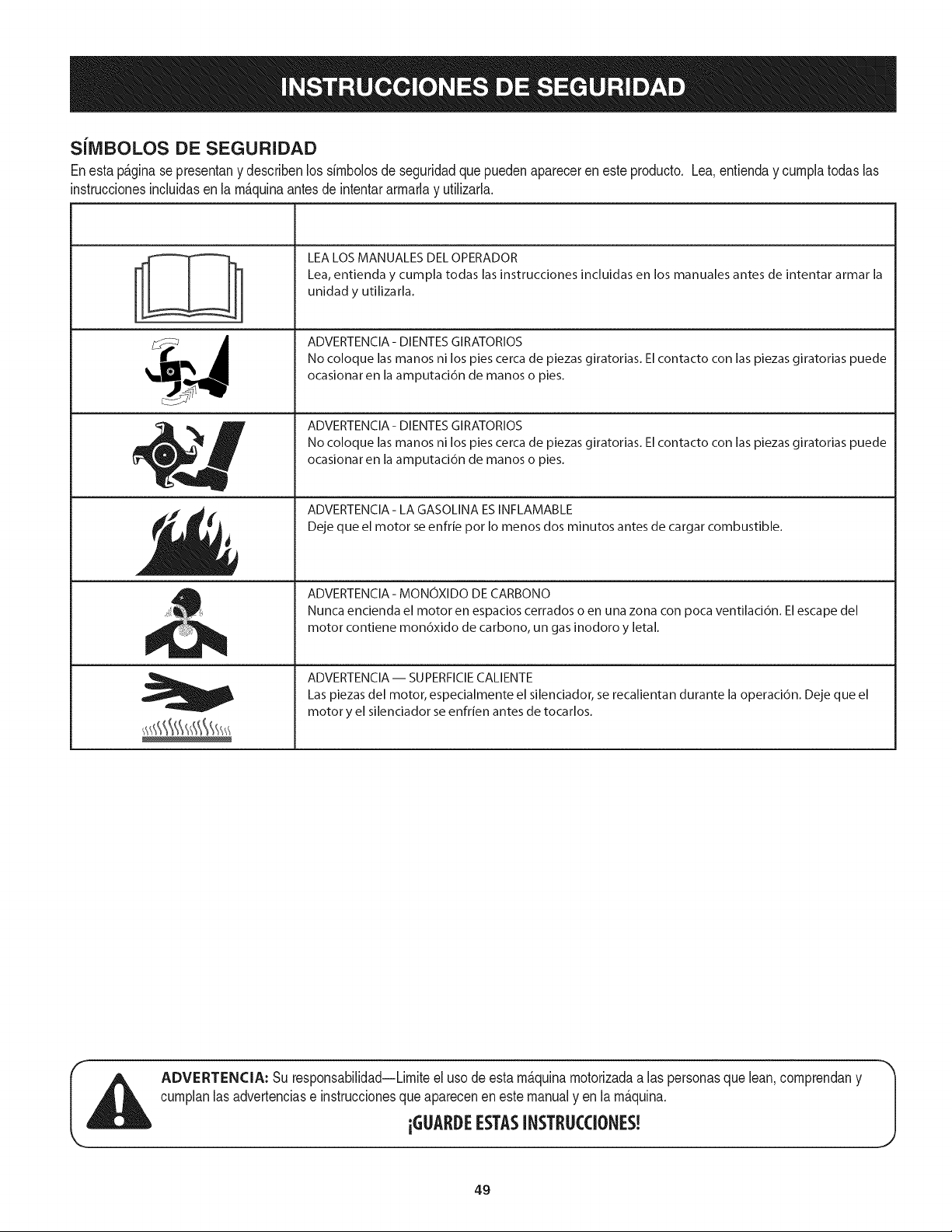
SiIVIBOLOS DE SEGURIDAD
Enestap&ginase presentany describenlos simbolosde seguridadquepuedenaparecerenesteproducto. Lea,entienday cumplatodaslas
instruccionesincluidasen la m_quinaantes de intentararmarlay utilizarla.
-'I °_
I I
I I
t i
i
, i
LEA LOS MANUALES DEL OPERADOR
Lea, entienda y cumpla todas las instrucciones incluidas en los manuales antes de intentar armar la
unidad y utilizarla.
ADVERTENCIA- DIENTES GIRATORIOS
No coloque las manos ni los pies cerca de piezas giratorias. El contacto con las piezas giratorias puede
ocasionar en la amputaci6n de manos o pies.
ADVERTENCIA- DIENTES GIRATORIOS
No coloque las manos ni los pies cerca de piezas giratorias. El contacto con las piezas giratorias puede
ocasionar en la amputaci6n de manos o pies.
ADVERTENClA- LA GASOLINA ESINFLAMABLE
Deje que el motor se enfrie pot Io menos dos minutos antes de cargar combustible.
ADVERTENCIA - MONOXIDO DE CARBONO
Nunca encienda el motor en espacios cerrados o en una zona con poca ventilaci6n. El escape del
motor contiene mon6xido de carbono, un gas inodoro y letal.
ADVERTENCIA- SUPERFIClE CALIENTE
Las piezas del motor, especialmente el silenciador, se recalientan durante la operaci6n. Deje que el
motor y el silenciador se enfrien antes de tocarlos.
ADVERTENCIA: Su responsabilidad--Limiteel uso deestam_quinamotorizadaa las personasquelean,comprendany
cumplanlas advertenciase instruccionesque aparecenen este manualy en la m_quina.
iGUARDEESTASINSTRUCCIONES!
49
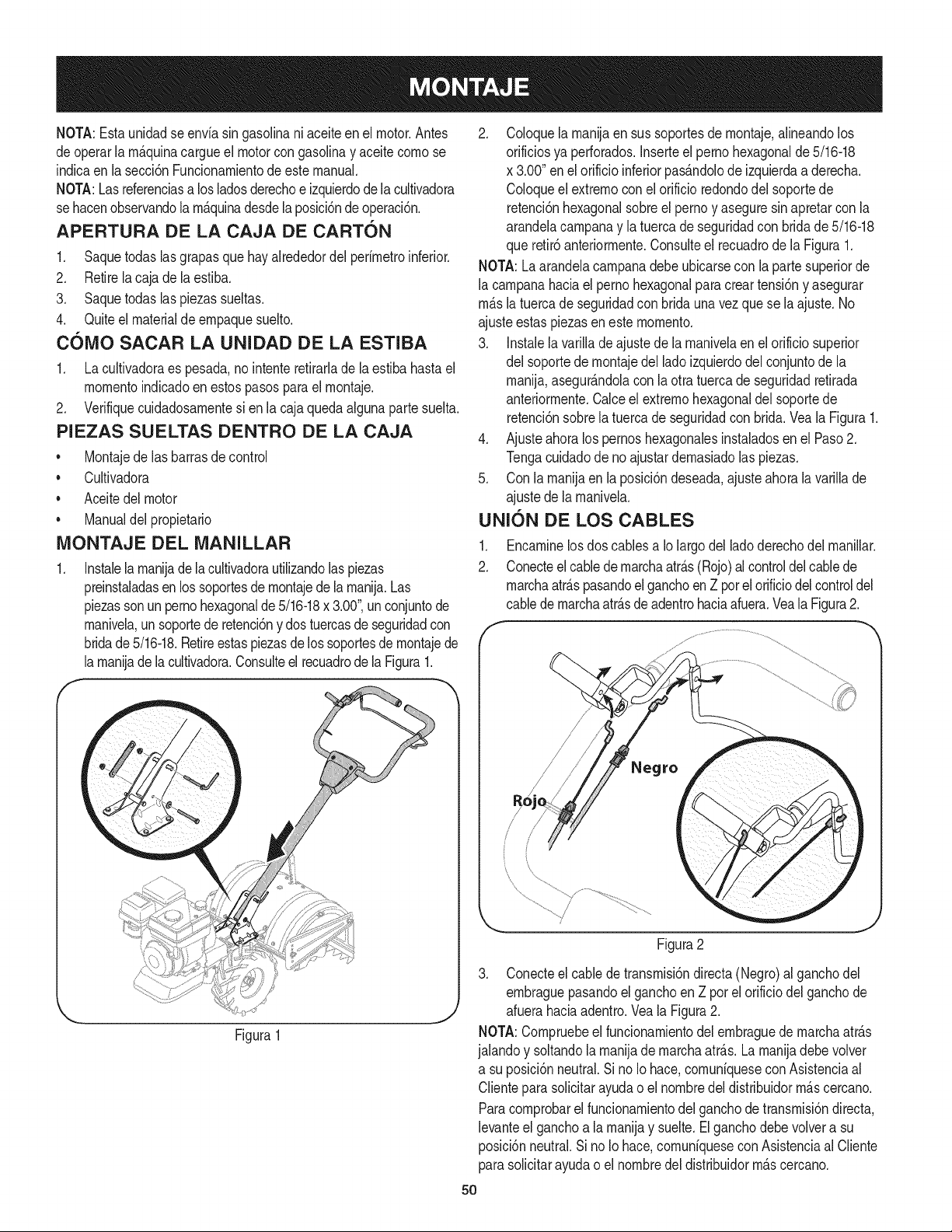
NOTA:Estaunidadse envfasingasolinaniaceiteen el motor.Antes
deoperarlam_.quinacargueel motorcongasolinay aceitecomose
indicaen la secci6nFuncionamientode estemanual.
NOTA:Lasreferenciasa losladosderechoe izquierdode lacultivadora
se hacenobservandola m_.quinadesdela posici6nde operaci6n.
APERTURA DE LA CAJA DE CARTON
1. Saquetodas lasgrapasque hayalrededordel perfmetroinferior.
2. Retirela cajade laestiba.
3. Saquetodas laspiezassueltas.
4. Quiteel materialdeempaquesuelto.
cOMO SACAR LA UNIDAD DE LA ESTIBA
1. La cultivadoraes pesada,no intenteretirarlade la estiba hastael
momentoindicadoenestospasosparael montaje.
2. Verifiquecuidadosamentesi enla cajaquedaalguna partesuelta.
PIEZAS SUELTAS DENTRO DE LA CAJA
• Montajede las barrasde control
• Cultivadora
• Aceitedel motor
• Manualdel propietario
MONTAJE DEL MANILLAR
Instalelamanijadelacultivadorautilizandolaspiezas
preinstaladasen los soportesde montajedela manija.Las
piezasson unpernohexagonalde5/16-18x 3.00",un conjuntode
manivela,un soportede retenci6ny dos tuercasde seguridadcon
bridade5/16-18.Retireestaspiezasde lossoportesde montajede
lamanijade lacultivadora.Consulteel recuadrode la Figura1.
2. Coloquelamanijaen sus soportesdemontaje,aNneandolos
orificiosya perforados.Inserteel pernohexagonalde5/16-18
x 3.00"enel orificioinferiorpas_.ndolode izquierdaaderecha.
Coloqueel extremocon el orificioredondodelsoportede
retenci6nhexagonalsobreel pernoy aseguresinapretarconla
arandelacampanay latuerca de seguridadcon bridade5/16-18
que retir6anteriormente.Consulteel recuadrode la Figura1.
NOTA:La arandelacampanadebeubicarsecon la partesuperiorde
la campanahaciael pernohexagonalparacreartensi6ny asegurar
m_.sla tuercade seguridadcon brida una vez que se laajuste.No
ajusteestas piezasen este momento.
3. Instalela varillade ajustede la manivelaen el orificiosuperior
del soportedemontajedel ladoizquierdodelconjuntodela
manija,asegurAndolacon la otra tuercade seguridadretirada
anteriormente.Calceel extremohexagonaldel soportede
retenci6nsobrelatuercadeseguridadcon brida.Vea la Figura1.
4. Ajusteahora los pernoshexagonalesinstaladosen el Paso2.
Tengacuidadodeno ajustardemasiadolaspiezas.
5. Con la manijaen laposici6ndeseada,ajusteahorala variNade
ajustede la manivela.
UNION DE LOS CABLES
.
2.
Encaminelosdos cablesa Io largodel ladoderechodel manillar.
Conecteelcablede marchaatr_.s(Rojo)al controldelcablede
marchaatr_.spasandoel ganchoen Z porelorificiodelcontroldel
cablede marchaatr&sdeadentrohaciaafuera.VealaFigura2.
Figura1
Figura2
3. Conecteel cablede transmisi6ndirecta (Negro)al ganchodel
embraguepasandoel ganchoen Z pot el orificiodel ganchode
afuerahaciaadentro.Veala Figura2.
NOTA:Compruebeel funcionamientodel embraguede marchaatrAs
jalandoy soltandolamanijade marchaatrAs.La manijadebevolver
a su posici6nneutral.Si no Io hace,comunfqueseconAsistenciaal
Clienteparasolicitarayudao el nombredeldistribuidorm_.scercano.
Paracomprobarelfuncionamientodel ganchodetransmisi6ndirecta,
levanteel ganchoa la manijay suelte.Elganchodebe volvera su
posici6nneutral.Si noIo hace,comunfqueseconAsistenciaal CNente
parasolicitarayudao el nombredel distribuidorm_.scercano.
5O
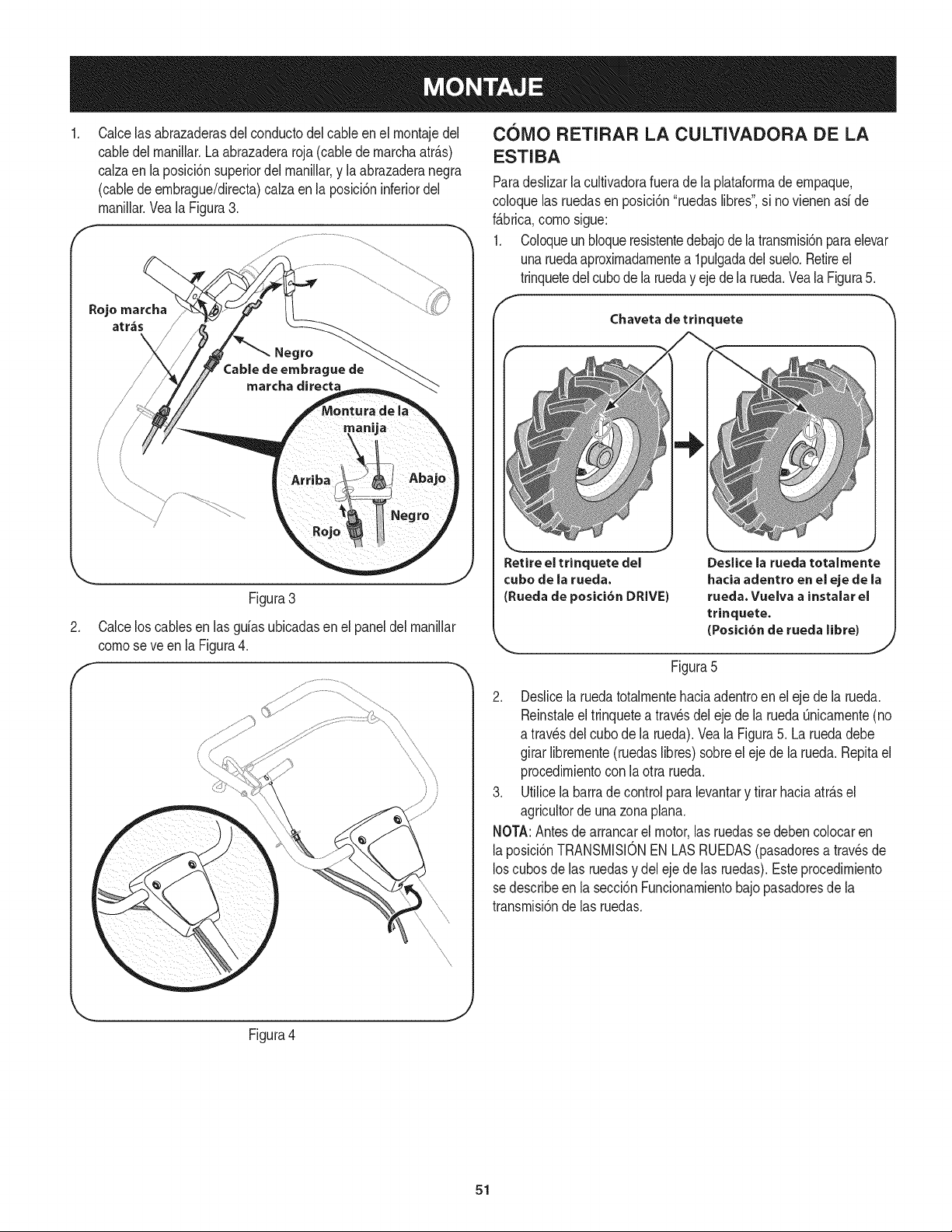
Calcelas abrazaderasdel conductodel cableen el rnontajedel
cabledel rnanillar.La abrazaderaroja(cablede rnarchaatr_.s)
calzaen la posici6nsuperiordel rnanillar,y la abrazaderanegra
(cablede ernbrague/directa)calzaen la posici6ninferiordel
rnanillar.Vea la Figura3.
Rojo marcha
atr,_s /
/
F
Figura3
2. Calcelos cablesen las guiasubicadasen el paneldel rnanillar
comese ve en la Figura4.
F
COiVlO RETIRAR LA CULTIVADORA DE LA
ESTIBA
Paradeslizarlacultivadorafuerade la plataforrnade ernpaque,
coloquelas ruedasen posici6n"ruedaslibres",si novienenasi de
f_.brica,comesigue:
1. Coloqueunbloqueresistentedebajodelatransrnisi6nparaelevar
unaruedaaproxirnadarnentea lpulgadadelsuelo.Retireel
trinquetedelcubede la rueday ejedela rueda.Veala Figura5.
f
Chaveta de trinquete
Retire el trinquete del
cube de la rueda.
(Rueda de pesici6n DRIVE)
Deslice la rueda totalmente
haciaadentroen el eje de la
rueda.Vuelvaa instalarel
trinquete.
(Pesici6nde rueda libre)
J
Figura5
2. Deslicela ruedatotalrnentehaciaadentroen el eje de la rueda.
Reinstaleel trinquetea travesdel ejede la ruedaQnicarnente(no
a travesdel cubede la rueda).Veala Figura5. Laruedadebe
girarlibrernente(ruedaslibres)sobreel eje de la rueda.Repitael
procedirnientoconla otra rueda.
3. Utilicela barrade controlpara levantary firarhaciaatr_.sel
agricultordeunazonaplana.
NOTA:Antesde arrancarel motor,las ruedasse debencolocaren
laposici6nTRANSMISlONEN LASRUEDAS(pasadoresa travesde
loscubes de las ruedasy delejede las ruedas).Este procedirniento
sedescribeen la secci6nFuncionarnientobajo pasadoresde la
transrnisi6nde las ruedas.
Figura4
J
51
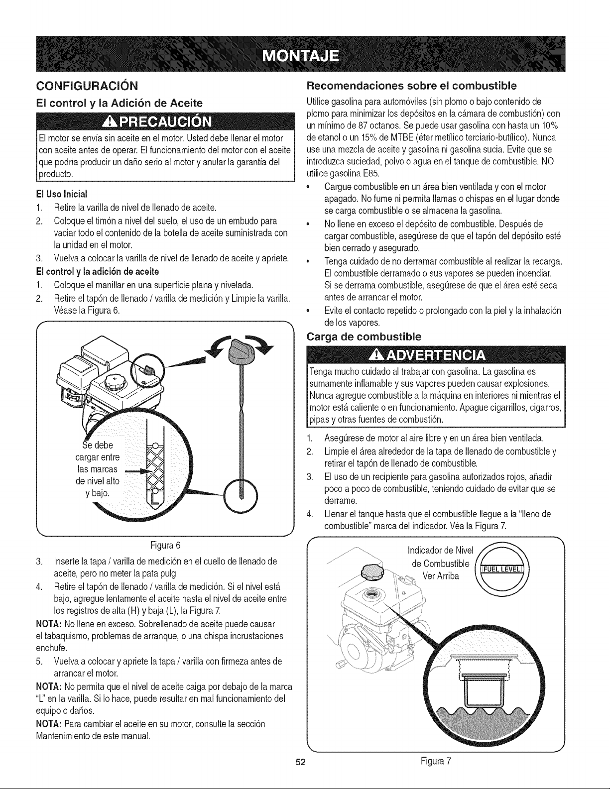
CONFIGURACION
El control y la Adici6n de Aceite
Elmotorseenvia sinaceite en el motor.Usteddebe Ilenarel motor
conaceiteantes de operar.El fundonamientodel motorcon elaceite
Ique podriaprodudr un daSoserioal motory anularla garantiadel
[producto,
El UsoInicial
1, Retirela varillade nivelde Ilenadode aceite,
2, Coloqueel fim6na niveldel suelo,el usode unembudopara
vaciartodoel contenidode la botellade aceitesuministradacon
la unidadenel motor,
3, Vuelvaa colocarla varillade nivelde Ilenadode aceitey apriete,
El control y la adici6n de aceite
1, Coloqueel manillaren una superficiephna y nivelada,
2, Retireel tap6ndeIlenado/ varillade medici6ny Limpiela varilla.
Wase la Figura6.
r
Se debe
cargarentre
las marcas
denivelalto
y bajo.
Figura6
3. Insertelatapa/ varillade medici6nenel cuellode Ilenadode
aceite,perono meterla patapulg
4. Retireel tap6ndeIlenado/ varillade medici6n.Si el nivelest,.
bajo,agreguelentamenteel aceite hastael niveldeaceiteentre
los registrosde alta (H) y baja (L),la Figura7.
NOTA: NoIleneen exceso.Sobrellenadode aceitepuedecausar
eltabaquismo,problemasde arranque,o unachispaincrustaciones
enchufe.
5. Vuelvaa colocary aprietela tapa / varillacon firmezaantesde
arrancarel motor.
NOTA: Nopermitaqueel nivelde aceitecaiga pordebajode lamarca
"L"en lavarilla.Si Io hace,puederesultaren realfuncionamientodel
equipoo da_os.
NOTA: Paracambiarel aceiteen su motor,consultela secci6n
Mantenimientodeeste manual.
Recomendaciones sobre el combustible
Utilicegasolinaparaautom6viles(sinplomoo bajocontenidode
plomopara minimizarlosdep6sitosen lac_.maradecombusti6n)con
un minimode87 octanos.Sepuedeusargasolinacon hastaun 10%
de etanolo un 15%de MTBE(etermefilicoterciario-bufilico).Nunca
use una mezclade aceitey gasolinani gasolinasucia.Evitequese
introduzcasuciedad,polvoo aguaen el tanquedecombustible.NO
utilicegasolinaE85.
• Carguecombustibleen un_.reabien ventiladay con el motor
apagado.No fume ni permitallamaso chispasen el lugardonde
se cargacombustibleo se almacenalagasolina.
• NoIleneen excesoel dep6sitode combustible.Despu_sde
cargarcombustible,asegQresedequeel tap6ndel dep6sitoest_
biencerradoy asegurado.
• Tengacuidadodeno derramarcombustibleal realizarla recarga.
Elcombustiblederramadoo susvaporesse puedenincendiar.
Si se derramacombustible,asegQresede queel _.reaest_seca
antesdearrancarel motor.
• Eviteel contactorepetidoo prolongadocon la piel y la inhalaci6n
de los vapores.
Carga de combustible
Tengamuchocuidadoal trabajarcongasolina.Lagaso%aes
sumamenteinflamabley susvaporespuedencausarexplosiones.
Nuncaagreguecombustiblea la m_.quinaen interioresni mientrasel
motorest,.calienteo enfuncionamiento.Apaguecigarrillos,cigarros,
pipasy otrasfuentesdecombusti6n.
1. AsegQresede motoralaire libreyen un _.reabien ventilada.
2. Limpieel _.reaalrededorde la tapade Ilenadodecombustibley
retirarel tap6nde Ilenadode combustible.
3. El usode un recipienteparagasolinaautorizadosrojos,a_adir
poco a pocodecombustible,teniendocuidadode evitarque se
derrame.
4. Llenarel tanquehastaque el combustibleIleguea la "llenode
combustible"marcadel indicador.Wa la Figura7.
52 Figura7
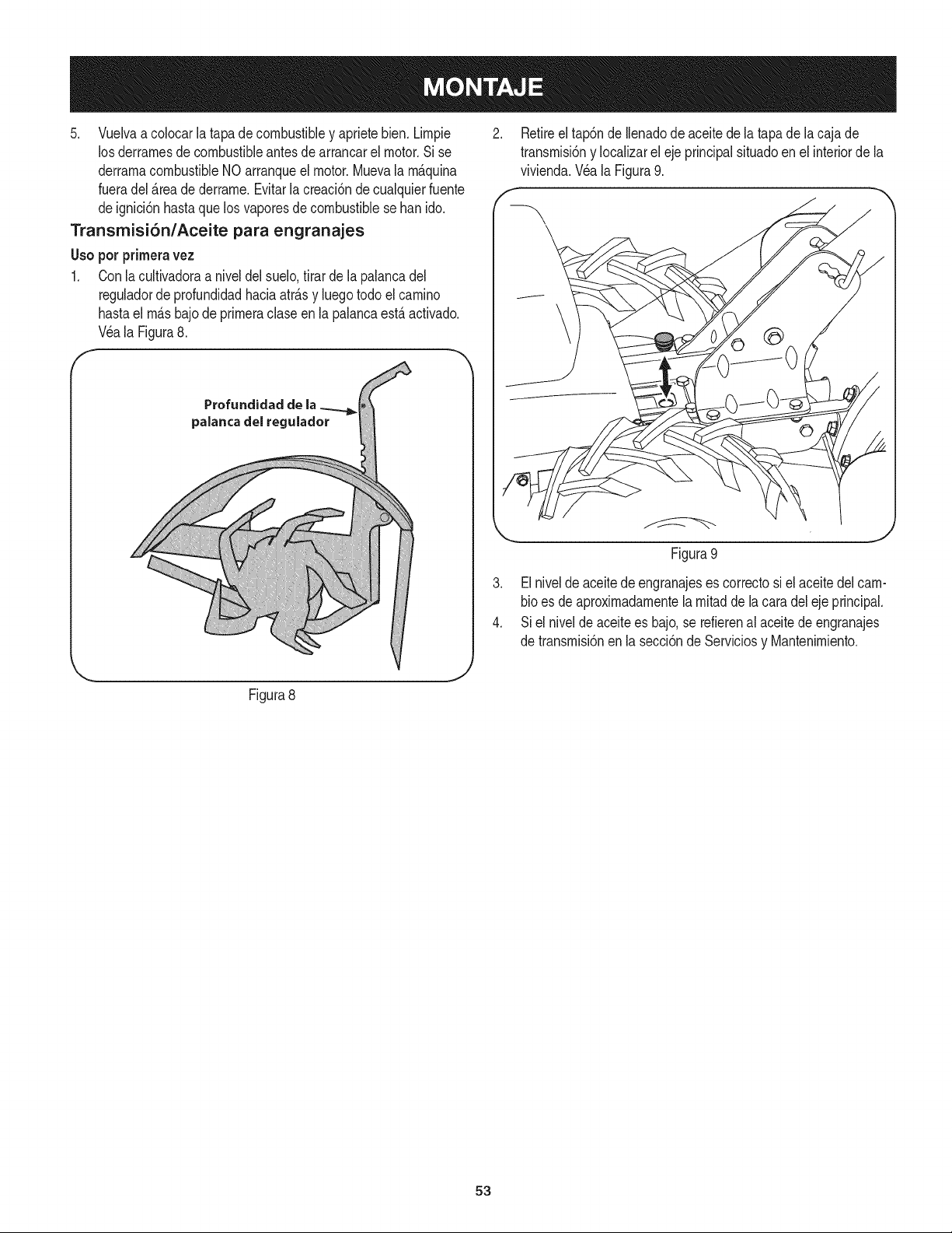
5. Vuelvaacolocarlatapadecombustibleyaprietebien.Lirnpie
losderrarnesdecombustibleantesdearrancarelmotor.Sise
derrarnacombustibleNOarranqueelmotor.Muevalarn_.quina
fueradel_.readederrarne.Evitarlacreaci6ndecualquierfuente
deignici6nhastaquelosvaporesdecombustiblesebanido.
Transmisi6n/Aceite para engranajes
Usopotprirneravez
1. Conla cultivadoraa niveldel suelo,tirarde la palancadel
reguladorde profundidadhaciaatr_.sy luegotodoel carnino
hastael rn_.sbajodeprirneraclaseen la palancaest,. activado.
Wa la Figura8.
2. Retireel tap6nde Ilenadodeaceitedela tapade la caja de
transrnisi6ny Iocalizarel ejeprincipalsituadoen elinteriorde la
vivienda.Wa la Figura9.
f -,
--X
\
'_., j
Figura8
3. El niveldeaceitedeengranajeses correctosi elaceitedelcam-
bioes deaproxirnadarnentela rnitadde la caradel eje principal.
4. Si el niveldeaceitees bajo,se refierenalaceite de engranajes
de transrnisi6nen la secci6nde Serviciosy Mantenirniento.
53

f
Manija de marcha arras
Tap6n de
combustible
Silenciador
Filtro de aire
Tap6n de llenaclo
y varilla del nivel
de aceite
Gancho del embrague
de marcha directa y
engranaje de dientes.
ulador de profundidad
uste de la altura de la manija
Controlde
obturaci6n
Protector de dientes trasero
Dientes
Tire de la manija del
arrancador
Drenaje del aceite
Pasador de transmisi6n en las ruedas
Ahoraquetienela cultivadorapreparadaparafuncionar,farniliaricese
conloscontrolesy funciones.Encontrar_.las descripcionesen las
siguientesdos p_.ginasy las ilustracionesen _sta.Esteconocirnientole
_errnitir_.utilizarsunuevoequipoasu rn_.xirnacapacidad.
AIoperarunacultivadoraes posibleque arrojeobjetosextra_osa
losojos, Iocualpodriacausarleslesionesgraves.Utilicesiernprelos
anteojosde seguridadconesta unidado protectoresparaojosrnientra._
labray rnientrasrealizaajusteso reparaciones.
Figura13
CONTROL DE OBTURACION
MANIJA DEL ARRANCADOR DE RETROCESO
Estarnanijase utilizaparaarrancarel motor.Veala Figura10.
CONTROL DEL ESTRANGULADOR
,J
Elcontroldelcebadorse encuentraen la parteposteriordelmotor,y
se activahaciendogirarlapalancaa la posici6nCHOKE(cebador).
AI activarel controldelcebadorsecierrala placadel cebadordel
carburadory estoayudaa ponerenrnarchael motor.VealaFigura9.
FILTRO DE AIRE
Elfiltrodeairees un dispositivode la tornade airedel motorque irnpide
la entradade polvoy suciedadenel motor.VealaFigura10.
SILENCIADOR
Elescapedelmotorsaledel motora travesdel silenciador.Veala
Figura10.
MANIJA DE MARCHA ATRAS
Larnanijade rnarchaatr_.scontrolalatransrnisi6ndecontrarnarchade
las ruedasy losdientes.Veala Figura10.
Elcontroldel reguladorest,. ubicadoen lapartedelanteradel motor.
Regulalavelocidaddelmotor,y IoapagacuandoseIo colocaen la
posici6nSTOP(detenci6n).Veala Figura10.
Curnple con los estandares de seguridad de ANSI
LascultivadorasCraftsmancurnplencon lasnorrnasde seguridaddel InstitutoNacionalArnericanode Norrnalizaci6n(ANSI).
54
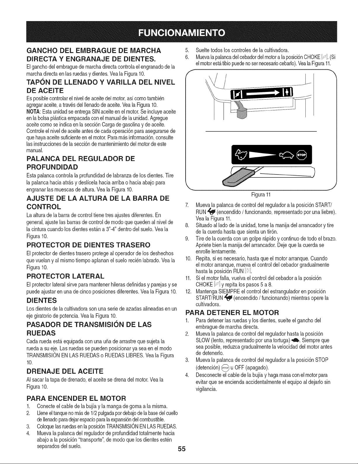
GANCHO DEL EMBRAGUE DE MARCHA
DIRECTA Y ENGRANAJE DE DIENTES.
Elganchodelernbraguede rnarchadirectacontrolaelengranadode la
rnarchadirectaen lasruedasy dientes.Veala Figura10.
TAPON DE LLENADO Y VARILLA DEL NIVEL
DE ACEITE
Es posiblecontrolarelnivelde aceitedelmotor,asicornotarnbi_n
agregaraceite,a travesdelIlenadode aceite.Veala Figura10.
NOTA:EstaunidadseentregaSINaceiteenel motor.Se incluyeaceite
enla bolsapl_.sticaernpacadaconelmanualdela unidad.Agregue
aceitecornoseindicaen la secci6nCargadegasolinay de aceite.
Controleel niveldeaceiteantesdecadaoperaci6nparaasegurarsede
quehayaaceitesuficienteen elmotor.Pararn_.sinforrnaci6n,consulte
lasinstruccionesde la secci6nde rnantenirnientodel motorde este
manual.
PALANCA DEL REGULADOR DE
PROFUNDIDAD
Estapalancacontrolala profundidadde labranzade losdientes.Tire
la palancahaciaatr_.sy deslicelahaciaarribao haciaabajopara
engranarlas rnuescasde altura.Vea la Figura10.
AJUSTE DE LA ALTURA DE LA BARRA DE
CONTROL
Laalturade la barrade control tienetresajustesdiferentes.En
general,ajustelas barrasdecontrolde rnodoquequedenal nivelde
la cinturacuandolos dientesest_.na 3"-4"dentrodel suelo.Vea la
Figura10.
PROTECTOR DE DIENTES TRASERO
Elprotectorde dientestraseroprotegeal operadorde los deshechos
quevuelany al rnisrnotiernpoaplananel sueloreci_nlabrado.Veala
Figura10.
PROTECTOR LATERAL
Elprotectorlateralsirve pararnantenerhilerasdefinidasy parejasy se
puedeajustaren unadecincoposicionesdiferentes.Veala Figura10.
DIENTES
Losdientesde la cultivadorason unaseriede azadasalineadasenun
ejegiratoriode potencia.Veala Figura10.
PASADOR DE TRANSMISION DE LAS
RUEDAS
Cadaruedaest,. equipadacon una u_a de arrastreque sujetala
ruedaa su eje. Las ruedasse puedenposicionarya seaen el rnodo
TRANSMISIONENLAS RUEDASo RUEDASLIBRES.Veala Figura
10.
DRENAJE DEL ACEITE
AI sacarla tapadedrenado,el aceitese drenadel motor.Yeala
Figura10.
PARA ENCENDER EL MOTOR
1. Conecteel cablede la bujfay larnangadegornaa la rnisrna.
2. Ueneeltanquenorn_.sde1/2pulgadapotdebajodelabasedel cuello
deIlenadoparadejarespacioparalaexpansi6ndelcombustible.
3. Coloquelasruedasen la posici6nTRANSMISIONENLASRUEDAS.
4. Muevala palancadel reguladorde profundidadtotalrnentehacia
abajoa la posici6n"transporte",de rnodoquelosdientesest_n
separadosdelsuelo. 55
5. Sueltetodos loscontrolesde lacultivadora.
6. Muevala palancadelcebadordelmotora laposici6nCHOKE[];_.(Si
elmotorest,.tibiopuedenosetnecesariocebarlo).VealaFigura11.
E
)
_. ,J
Figura11
7. Muevala palancade controldel reguladora la posici6nSTART/
RUN'_ (encendido/ funcionando,representadopor una liebre).
Veala Figura11.
8. Situadoal lado de la unidad,tome la rnanijadel arrancadory tire
de lacuerdahasta que sientaun tir6n.
9. Tire dela cuerdaconun golper_.pidoy continuode todoel brazo.
Aprietebien la rnanijadelarrancador.Dejequelacuerdase
enrollelentarnente.
10. Repita,si es necesario,hastaqueel motorarranque.Cuando
el motorarranque,rnuevaelcontroldel cebadorgradualrnente
hastala posici6nRUNI_!.
11. Si el motorfalla, vuelvael controldel cebadora la posici6n
CHOKEi_-_[:;y repitalos pasos5 a 8.
12. MantengaSIE,MPREel controldel estranguladoren posici6n
START/RUN_ (encendido/ funcionando)rnientrasopere la
cultivadora.
PARA DETENER EL MOTOR
1. Paradetenerlas ruedasy los dientes,suelteel ganchodel
ernbraguedernarchadirecta.
2. Muevala palancade controldel reguladorhastala posici6n
SLOW(lento,representadopor una tortuga),,rib..Siernpreque
seaposible,reduzcagradualrnentela velocidaddelmotorantes
de detenerlo.
3. Muevala palancade controldel reguladora la posici6nSTOP
(detenci6n)_ u OFF(apagado).
4. Desconecteel cablede la bujfay hagarnasaconelmotorpara
evitarquese enciendaaccidentalrnenteel equipoal dejarlosin
vigilancia.
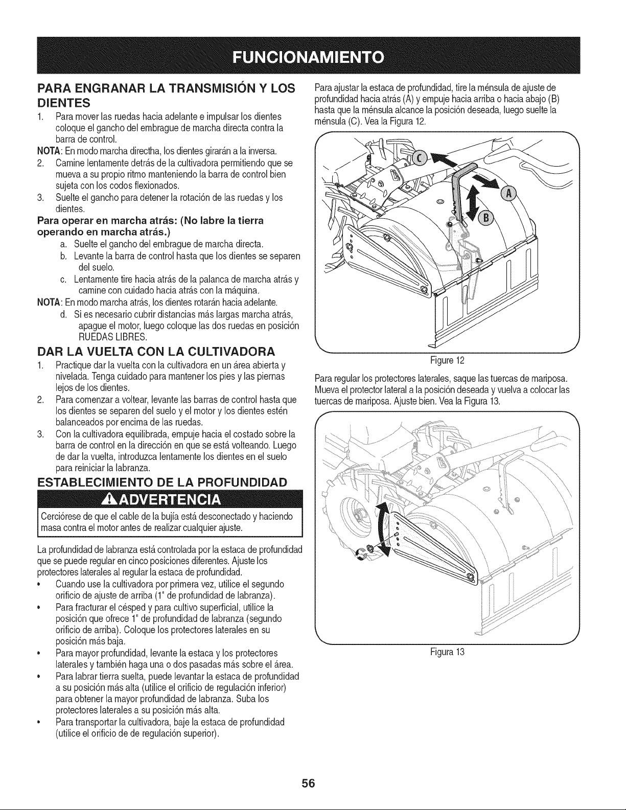
PARA ENGRANAR LA TRANSiVIISION Y LOS
DIENTES
1. Paramoverlas ruedashaciaadelantee impulsarlos dientes
coloqueel ganchodelembraguede marchadirectacontrala
barradecontrol.
NOTA:Enmodomarchadirectha,losdientesgirar_.nala inversa.
2. Caminelentamentedetr_.sde lacultivadorapermitiendoquese
muevaa su propioritmo manteniendola barrade control bien
sujetacon los codosflexionados.
3. Suelteelganchopara detenerla rotaci6nde las ruedasy los
dientes.
Para operar en marcha arras: (No labre la tierra
operando en marcha arras.)
a. Suelteelganchodel embraguede marchadirecta.
b. Levantela barrade controlhastaquelosdientes se separen
delsuelo.
c. Lentamentetire haciaatr_.sde la palancade marchaatr_.sy
caminecon cuidadohaciaatr_.scon la m_.quina.
NOTA:Enmodomarchaatr_.s,losdientesrotar_.nhaciaadelante.
d. Si es necesariocubrirdistanciasm_.slargasmarchaatr_.s,
apagueel motor,luego coloquelas dos ruedasen posici6n
RUEDASLIBRES.
DAR LA VUELTA CON LA CULTIVADORA
1. Practiquedar la vueltacon la cultivadoraen un _.reaabiertay
nivelada.Tengacuidadoparamantenerlos piesy las piernas
lejosde los dientes.
2. Paracomenzara voltear,levantelas barrasdecontrolhastaque
los dientesse separendelsueloy el motory los dientesest_n
balanceadosporencimade las ruedas.
3. Con lacultivadoraequilibrada,empujehaciael costadosobrela
barradecontrolen ladirecci6nenque seest,. volteando.Luego
de darlavuelta,introduzcalentamentelosdientesen el suelo
parareiniciarla labranza.
ESTABLECllVIIENTO DE LA PROFUNDIDAD
Cerci6resedequeelcablede la bujia est,.desconectadoy haciendo
masacontrael motorantesde realizarcualquierajuste.
La profundidadde labranzaest,.controladaporlaestacadeprofundidad
quese puederegularen cinco posicionesdiferentes.Ajustelos
protectoreslateralesal regularla estacade profundidad.
• Cuandouse lacultivadoraporprimeravez, utiliceel segundo
orificiode ajustedearriba(1"de profundidadde labranza).
• Parafracturarelcespedy paracultivosuperficial,utilicela
posici6nqueofrece1"de profundidadde labranza(segundo
orificiode arriba).Coloquelos protectoreslateralesen su
posici6nm_.sbaja.
• Para mayorprofundidad,levantela estacay los protectores
lateralesy tambi_nhagaunao dos pasadasm_.ssobreel _.rea.
• Para labrartierrasuelta,puedelevantarla estacade profundidad
a su posici6nm_.salta (utiliceelorificiode regulaci6ninferior)
paraobtenerla mayorprofundidaddelabranza.Subalos
protectoreslateralesa su posici6nm_.salta.
• Paratransportarla cultivadora,bajela estacade profundidad
(utiliceel orificiode de regulaci6nsuperior).
Paraajustarlaestacade profundidad,tirela m_nsuladeajustede
profundidadhaciaatr_.s(A)y empujehaciaarribaohaciaabajo(B)
hastaquela m_nsulaalcancela posici6ndeseada,luegosueltela
m_nsula(C).Veala Figura12.
f
Figure12
Pararegularlosprotectoreslaterales,saquelastuercasdemariposa.
Muevael protectorlaterala la posici6ndeseaday vuelvaa colocarlas
tuercasdemariposa.Ajustebien.Veala Figura13.
f
Figura13
J
56
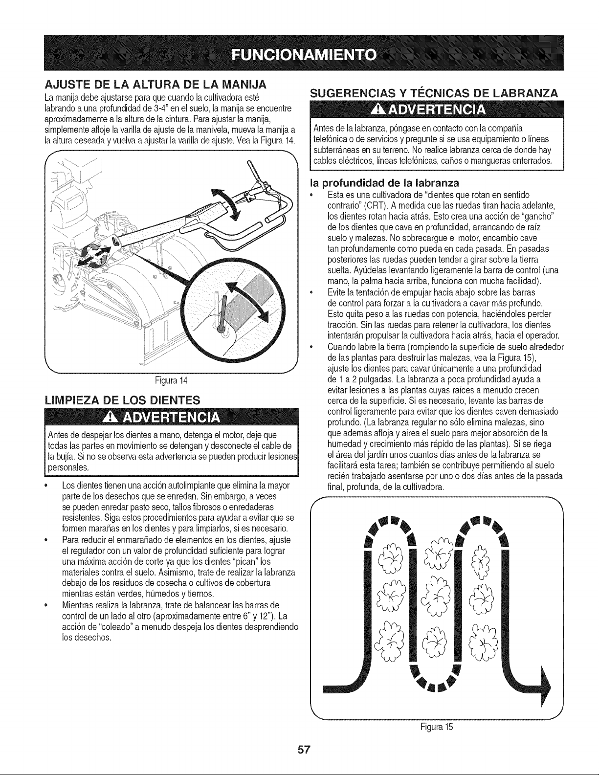
AJUSTE DE LA ALTURA DE LA MANIJA
Larnanijadebeajustarseparaquecuandolacultivadoraest_
labrandoauna profundidadde 3-4"enelsuelo,larnanijase encuentre
aproximadarnentea la alturade la cintura.Paraajustarla rnanija,
sirnplernenteaflojela varilladeajustede la rnanivela,rnuevalarnanijaa
la alturadeseaday vuelvaa ajustarla varillade ajuste.VealaFigura14.
Figura14
LIIVlPIEZA DE LOS DIENTES
Antesdedespejarlosdientesa rnano,detengael motor,dejeque
todaslas partesenrnovirnientose detengany desconecteel cablede
la bujfa.Sino seobservaestaadvertenciasepuedenproducirlesiones
personaes.
• Losdientestienenunaacci6nautolirnpiantequeelirninalamayor
partede losdesechosque seenredan.Sinembargo,a veces
se puedenenredarpastoseco,tallosfibrososo enredaderas
resistentes.Sigaestosprocedirnientosparaayudaraevitarquese
forrnenmaracasen losdientesy paralirnpiarlos,sies necesario.
• Parareducirel enrnara_adode elernentosen los dientes,ajuste
el reguladorcon unvalorde profundidadsuficienteparaIograr
unam_.xirnaacci6n de corteya quelos dientes"pican"los
rnaterialescontrael suelo.Asimisrno,tratede realizarla labranza
debajode los residuosde cosechao cultivosde cobertura
rnientrasest_.nverdes,hOrnedosy tiernos.
• Mientrasrealizala labranza,tratede balancearlasbarrasde
controlde unladoal otro(aproxirnadarnenteentre6" y 12").La
acci6nde "coleado"a rnenudodespejalos dientesdesprendiendo
los desechos.
SUGERENCIAS Y TC:CNICAS DE LABRANZA
Antesdelalabranza,p6ngaseencontactoconlacornpaSia
telef6nicao de serviciosy preguntesise usaequiparnientoo lineas
subterr_.neasensu terreno.Norealicelabranzacercadedondehay
cablesel_ctricos,lineastelef6nicas,caSoso rnanguerasenterrados.
la profundidad de la labranza
• Estaes unacultivadorade "dientesque rotanensentido
contrario"(CRT).A rnedidaque las ruedastitan haciaadelante,
losdientes rotanhaciaatr_.s.Estocreaunaacci6nde "gancho"
de los dientesquecava en profundidad,arrancandode rafz
sueloy rnalezas.No sobrecargueel motor,encarnbiocave
tan profundarnentecornopuedaencada pasada.Enpasadas
posterioreslas ruedaspuedentenderagirarsobrela tierra
suelta.AyOdelaslevantandoligerarnentela barrade control(una
rnano,lapalrnahaciaarriba,funcionacon rnuchafacilidad).
• Evitela tentaci6nde ernpujarhaciaabajo sobrelas barras
de controlparaforzara la cultivadoraa cavarrn_.sprofundo.
Estoquitapesoalas ruedascon potencia,haci_ndolesperder
tracci6n.Sinlas ruedaspararetenerlacultivadora,los dientes
intentar_.npropulsarla cultivadorahaciaatr_.s,haciael operador.
• Cuandolabrela tierra(rornpiendolasuperficiede sueloalrededor
de las plantasparadestruirlas rnalezas,vea la Figura15),
ajustelosdientespara cavarQnicarnentea una profundidad
de 1a 2pulgadas.Lalabranzaa pocaprofundidadayudaa
evitarlesionesalas plantascuyasraicesa rnenudocrecen
cercade lasuperficie.Sies necesario,levantelas barrasde
controlligerarnenteparaevitarquelos dientescavendernasiado
profundo.(Lalabranzaregularno s61oelirninarnalezas,sino
queadern_.saflojay aireael suelopararnejorabsorci6nde la
hurnedady crecirnientorn_.sr_.pidode las plantas).Si se riega
el _.readel jardinunoscuantosdfas antesde la labranzase
facilitate,estatarea;tarnbi_nse contribuyeperrnitiendoal suelo
reci_ntrabajadoasentarsepot unoo dosdias antesde la pasada
final,profunda,de la cultivadora.
J
Figura15
57
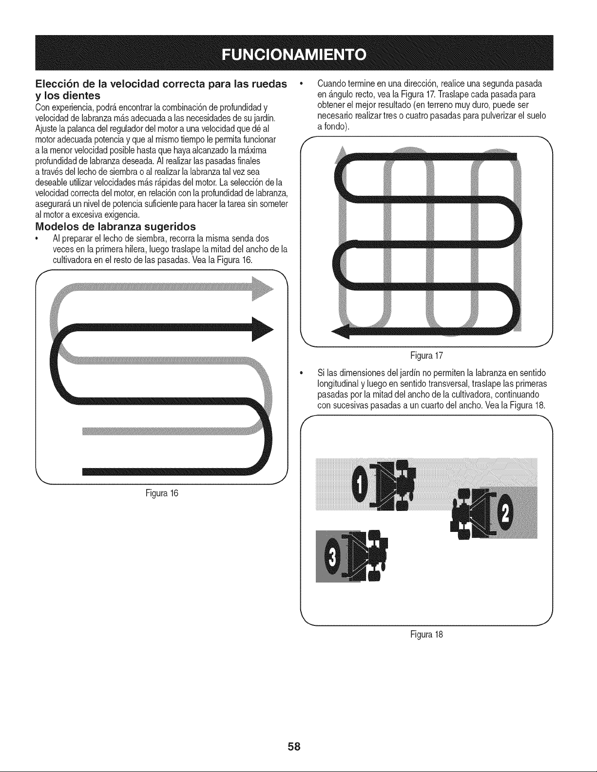
Elecci6n de la velocidad correcta para las ruedas
y los dientes
Conexperiencia,podr_,encontrarlacornbinaci6nde profundidady
velocidadde labranzarn_.sadecuadaalas necesidadesde sujardin.
Ajustela palancadel reguladordel motora unavelocidadque d_ al
motoradecuadapotenciay quealmisrnotiernpole perrnitafuncionar
a larnenorvelocidadposiblehastaquehayaalcanzadola maxima
profundidadde labranzadeseada.AI realizarlaspasadasfinales
atrav_sdellechode siernbrao alrealizarla labranzatalvez sea
deseableutilizarvelocidadesrn_.sr_.pidasdelmotor.Laselecci6nde la
velocidadcorrectadel motor,enrelaci6ncon laprofundidaddelabranza,
asegurar_,un niveldepotenciasuficienteparahacerla tareasinsorneter
almotoraexcesivaexigencia.
IVlodelos de labranza sugeridos
• A[ prepararel lechodesiernbra,recorrala rnisrnasendados
vecesen la prirnerahiiera,[uegotraslapela rnitaddel anchode la
cultivadoraen el restode las pasadas.Vea[aFigura16.
Cuandoterrnineen unadirecci6n,realiceunasegundapasada
en _.ngulorecto,veala Figura17.Traslapecada pasadapara
obtenerel rnejorresultado(enterrenornuyduro,puedeser
necesariorealizartreso cuatropasadasparapulverizarel suelo
a fondo).
f
_m_ m
/ m _ m
Figura17
Si las dirnensionesdel jardin no perrnitenla labranzaen sentido
longitudinaly luegoen sentidotransversal,traslapelasprirneras
pasadasporla rnitaddel anchode la cultivadora,continuando
con sucesivaspasadasa uncuartodelancho.Veala Figura18.
J
Figura16
Figura18
J
58
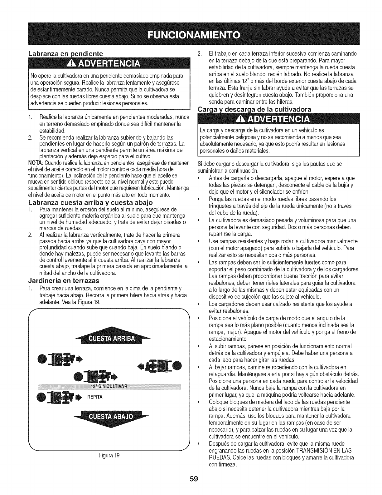
Labranza en pendiente
Nooperela cultivadoraen unapendientedernasiadoernpinadapara
unaoperaci6nsegura.Realicela labranzalentarnentey asegOrese
de estarfirrnernenteparado.Nuncaperrnitaquelacultivadorase
desplacecon lasruedaslibrescuestaabajo.Si noseobservaesta
advertenciasepuedenproducirlesionespersonales.
1. Realicela labranzaOnicarnenteen pendientesrnoderadas,nunca
enterrenodernasiadoernpinadodondeseadificilrnantenerla
estabilidad.
2. Se recorniendarealizarla labranzasubiendoy bajandolas
pendientesen lugardehacerlosegOnunpatr6nde terrazas.La
labranzaverticalen una pendienteperrniteun_rearn_xirnade
plantaci6ny adern_.sdejaespacioparael cultivo.
NOTA:Cuandorealicela labranzaen pendientes,aseguresedernantener
elniveldeaceitecorrectoenel motor(controlecadamediahorade
funcionarniento).Lainclinaci6ndelapendientehacequeel aceitese
rnuevaensentidooblicuorespectodesunivelnormaly estopuede
subalirnentarciertaspartesdelmotorquerequierenlubricaci6n.Mantenga
elniveldeaceitedemotorenel puntorn_saltoentodornornento.
Labranza cuesta arriba y cuesta abajo
1. Pararnantenerla erosi6ndel sueloal rninirno,asegOresede
agregarsuficienternateriaorg_nicaal sueloparaquernantenga
unnivelde hurnedadadecuado,y tratede evitardejar pisadaso
rnarcasde ruedas.
2. AI realizarla labranzaverticalrnente,trate de hacerla prirnera
pasadahaciaarriba ya quelacultivadoracavacon mayor
profundidadcuandosubequecuandobaja. En sueloblandoo
dondehay rnalezas,puedeser necesarioquelevantelas barras
decontrollevernenteal ir cuestaarriba.AI realizarla labranza
cuestaabajo,traslapela prirnerapasadaen aproxirnadarnentela
rnitaddel anchode la cultivadora.
Jardineria en terrazas
1. Paracrearuna terraza,cornienceen la cirnade la pendientey
trabajehaciaabajo. Recorrala prirnerahilerahaciaatr_.sy hacia
adelante.Veala Figura19.
F
to,
®
tl, REp,TA
Figura19
Eltrabajoen cadaterrazainferiorsucesivacornienzacarninando
en laterrazadebajodela queest_preparando.Paramayor
estabilidadde la cultivadora,siernprernantengala ruedacuesta
arribaenel sueloblando,reci_nlabrado.Norealicela labranza
en las Oltirnas12"o rn_.sdelhordeexteriorcuestaabajode cada
terraza.Esta franjasin labrarayudaa evitar que lasterrazasse
quiebreny desintegrencuestaabajo.Tarnbi_nproporcionauna
sendaparacarninarentre las hileras.
y descar¢ de la cultivadora
Lacargay descargade lacultivadoraenunvehiculoes
potencialrnentepeligrosay no se recorniendaa rnenosquesea
absolutarnentenecesario,ya queestopodriaresultarenlesiones
personalesoda_osrnateriales.
Sidebecargaro descargarlacultivadora,sigalaspautasquese
surninistrana continuaci6n.
• Antes de cargarlao descargarla,apagueel motor,esperea que
todaslas piezasse detengan,desconecteel cablede la bujiay
dejequeel motory elsilenciadorse enfrien.
• Pongalas ruedasenel rnodoruedaslibrespasandolos
trinquetesa travesdeleje de laruedaOnicarnente(noa traves
del cubode la rueda).
• La cultivadoraes dernasiadopesaday volurninosaparaque una
personalalevantecon seguridad.Doso rn_spersonasdeben
repartirselacarga.
• Use rarnpasresistentesy hagarodar la cultivadoramanualrnente
(conel motorapagado)parasubirlao bajarladel vehiculo.Para
realizarestose necesitandos o rn_spersonas.
• Lasrarnpasdebenser Io suficienternentefuertescornopara
soportarel pesocornbinadode la cultivadoray de loscargadores.
Lasrarnpasdebenproporcionarbuenatracci6nparaevitar
resbalones,debentenerrieleslateralesparaguiar la cultivadora
a Io largo de las misrnasy debenestar equipadascon un
dispositivode sujeci6nque las sujetealvehiculo.
• Loscargadoresdebenusarcalzadoresistentequelos ayudea
evitarresbalones.
• Posicioneel vehiculode cargade rnodoqueel _ngulodela
rarnpasea Iorn_spianoposible(cuantornenosinclinadaseala
rarnpa,rnejor).Apagueel motordel vehiculoy pongael frenode
estacionarniento.
• AI subir rarnpas,p_reseenposici6nde funcionarnientonormal
detr_.sde la cultivadoray ernpOjela.Debehaberunapersonaa
cada lado parahacergirarlas ruedas.
• AI bajarrarnpas,carnineretrocediendoconla cultivadoraen
retaguardia.Mant_ngasealerta por si hayalgOnobst_culodetr_s.
Posicioneunapersonaen cada ruedaparacontrolarla velocidad
de lacultivadora.Nuncabajelatampaconla cultivadoraen
primerlugar,ya que la rnaquinapodriavoltearsehaciaadelante.
• Coloquebloquesde rnaderadel ladode las ruedaspendiente
abajosi necesitadetenerlacultivadorarnientrasbajapor la
rarnpa.Adern_s,use los bloquespararnantenerla cultivadora
ternporalrnenteen su lugar en las rarnpas(encasodeser
necesario),y paracalzarlas ruedasen sulugar una vez que la
cultivadorase encuentreen el vehiculo.
• Despu_sde cargarla cultivadora,eviteque larnisrnaruede
engranandolas ruedasen la posici6nTRANSMISlONEN LAS
RUEDAS.Calcelas ruedasconbloquesy arnarrela cultivadora
con firrneza.
59
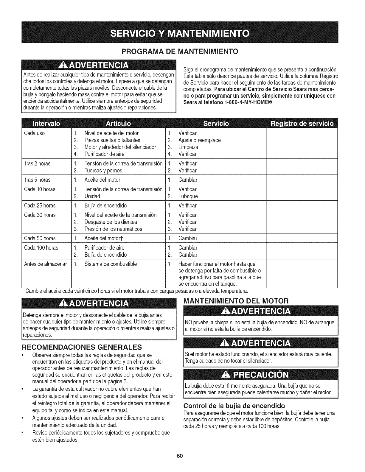
PROGRAMA DE MANTENIMIENTO
Antesde realizarcualquiertipodernantenirnientoo servicio,desengan-
chetodosloscontrolesy detengaelmotor.Esperea quesedetengan
cornpletarnentetodaslas piezasrn6viles.Desconecteelcablede la
bujiay p6ngalohaciendornasacontrael motorparaevitarquese
enciendaaccidentalrnente.Utilicesiernpreanteojosde seguridad
durantela operaci6no rnientrasrealizaajusteso reparaciones.
Sigael cronograrnade rnantenirnientoquese presentaa continuaci6n.
Estatabla s61odescribepautasde servicio.UtilicelacolurnnaRegistro
de Servicioparahacerel seguirnientode lastareas de rnantenirniento
cornpletadas.Paraubicar el Centro de Servicio Searsrn_scerca-
no o paraprogramarunservicio, simplementecomuniquese con
Sears al tel_fono 1-800-4-MY-HOME®
Cadauso
l_s2ho_s
l_s5ho_s
CadalOho_s
Cada25ho_s
1. Niveldeaceite del motor
2. Piezassueltasofaltantes
3. Motory alrededordelsilenciador
4. Purificadordeaire
1. Tensi6nde la correade transrnisi6n
2. Tuercasy pernos
1. Aceitedelmotor
1. Tensi6nde la correade transrnisi6n
2. Unidad
1. Bujiadeencendido
1. Niveldel aceitede la transrnisi6n
2. Desgastedelosdientes
3. Presi6nde los neurn_ticos
1. Aceitedelrnotort
1. Purificadordeaire
2. Bujfadeencendido
1. Sisternadecombustible
Carnbieel aceitecadaveinticincohorassi el motortrabajaconcargas
Detengasiernpreelmotory desconecteel cablede la bujiaantes
dehacercualquiertipo demantenirnientoo ajustes.Utilicesiernpre
anteojosdeseguridaddurantela operaci6no rnientrasrealizaajusteso
lreparacones.
1. Verificar
2. Ajusteo reernplace
3. Lirnpieza
4. Verificar
1. Verificar
2. Verificar
1. Carnbiar
1. Verificar
2. Lubrique
1. Verificar
Verificar
Verificar
Verificar
Cada30 horas 1.
2.
3.
Cada50horas 1. Carnbiar
Cada100horas 1. Carnbiar
2. Carnbiar
Antesdealrnacenar 1. Hacerfuncionarel motorhastaque
se detengapor falta de combustibleo
agregaraditivoparagasolinaa laque
se encuentraen eltanque.
3esadasoa elevadaternperatura.
MANTENIMIENTO DEL MOTOR
NOpruebela chispasi noestalabujfade encendido.NOdearranque
almotorsi no est&la bujiadeencendido.
RECOMENDACIONES GENERALES
• Observesiernpretodaslas reglasde seguridadque se
encuentranen las etiquetasdel productoyen el manualdel
operadorantesde realizarrnantenirniento.Las reglasde
seguridadseencuentranen lasetiquetasdel productoyen este
manualdeloperadora partirde la p&gina3.
• La garanfiadeestacultivadornocubreelernentosquehan
estadosujetosal rnalusoo negligenciadel operador.Pararecibir
el reintegrototal de la garantia,el operadordeber&rnantenerel
equipotal y cornose indicaen este manual.
• Algunosajustesdeben ser realizadosperi6dicarnenteparael
mantenirnientoadecuadode la unidad.
• Reviseperi6dicarnentetodos los sujetadoresy cornpruebeque
est_nbienajustados.
Sielmotorhaestadofuncionando,elsilenciadorestar&rnuycaliente.
Tengacuidadodeno tocarel silenciador.
Labujfadebeestarfirrnernenteasegurada.Unabujfaqueno se
encuentrebienaseguradapuedecalentarsernuchoy daSarel motor.
Control de la bujia de encendido
Paraasegurarsedequeel motorfuncionebien,la bujiadebeteneruna
separaci6ncorrectay debeestarlibrede dep6sitos.Controlelabujia
cada25 horasy reernpl&celacada100horas.
6O
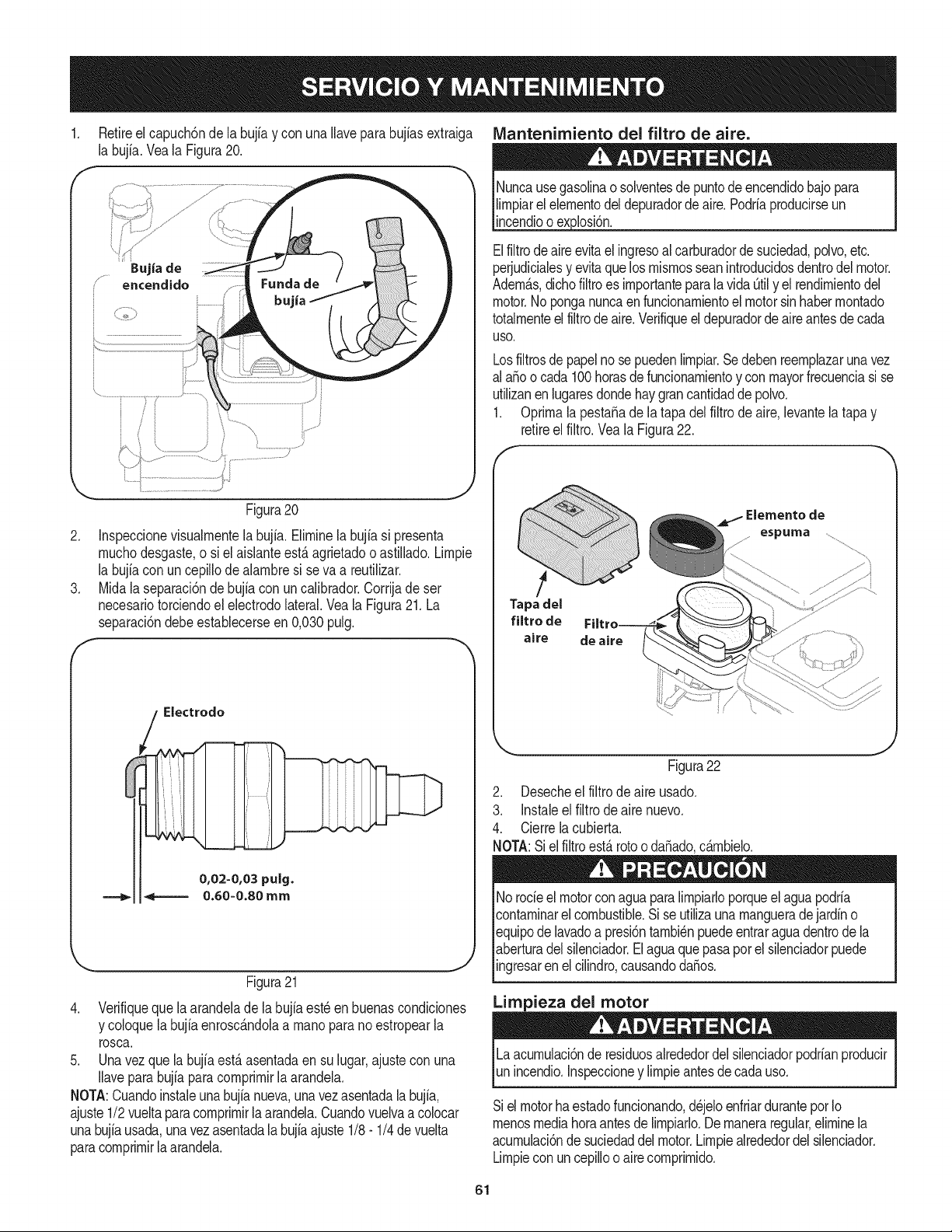
1. Retireel capuch6nde la bujia y con una Ilaveparabujiasextraiga
la bujia.Veala Figura20.
Figura20
2. Inspeccionevisualrnentela bujfa.Elirninela bujfasi presenta
rnuchodesgaste,o si el aislanteest,.agrietadoo astillado.Lirnpie
la bujfacon un cepillode alarnbresi seva a reutilizar.
3. Midala separaci6ndebujia con uncalibrador.Corrijade ser
necesariotorciendoel electrodolateral.Veala Figura21. La
separaci6ndebeestablecerseen 0,030pulg.
// Electrodo
Figura21
4. Verifiqueque laarandelade la bujfaest_enbuenascondiciones
y coloquelabujiaenrosc_.ndolaa rnanopara no estropearla
rosca.
5. Unavezquela bujiaest,.asentadaen sulugar,ajustecon una
Ilaveparabujfaparacomprirnirlaarandela.
NOTA:Cuandoinstaleunabujianueva,unavezasentadalabujia,
ajuste1/2vueltaparacomprirnirla arandela.Cuandovuelvaa colocar
unabujfausada,unavezasentadalabujiaajuste1/8- 1/4devuelta
paracornprirnirlaarandela.
IVlantenimiento del filtro de aire.
Nuncausegasolinaosolventesde puntodeencendidobajopara
lirnpiarel elernentodeldepuradordeaire.Podriaproducirseun
incendioo explosi6n.
Elfiltrodeaireevitael ingresoal carburadorde suciedad,polvo,etc.
perjudicialesy evitaquelos rnisrnosseanintroducidosdentrodel motor.
Adern_.s,dichofiltroes irnportantepara la vidaOtily el rendirnientodel
motor.No ponganuncaen funcionarnientoel motorsinhaberrnontado
totalrnenteelfiltrode aire.Verifiqueel depuradorde aire antesde cada
USO.
Losfiltrosde papelno se puedenlirnpiar.Sedebenreernplazarunavez
al a_oo cada100horasde funcionarnientoy conmayorfrecuenciasi se
utilizanen lugaresdondehaygrancantidaddepolvo.
1. Oprirnala pesta_ade la tapa delfiltrode air& levantelatapay
retireel filtro.Vea la Figura22.
......
Tapa del
filtro de
aire de aire
Elementode
espuma
j .....
Figura22
2. Desecheel filtrodeaire usado.
3. Instaleel filtro de aire nuevo.
4. Cierrelacubierta.
NOTA:Si el filtroest,. rotooda_ado,c_.rnbielo.
Norocieel motorconaguaparalirnpiarloporqueel aguapodria
contarninarel combustible.Sise utilizaunarnangueradejardn o
equipodelavadoa presi6ntarnbi_npuedeentraraguadentrode la
aberturadelsilenciador.Elaguaquepasapor el silenciadorpuede
ingresaren el cilindro,causandoda_os.
Limpieza del motor
Laacurnulaci6nde residuosalrededordel silenciadorpodrianproducir
unincendio.Inspeccioney lirnpieantesdecadauso.
Sielmotorhaestadofuncionando,d_jeloenfriardurantepotIo
rnenosmediahoraantesde lirnpiarlo.Dernaneraregular,elirninela
acurnulaci6ndesuciedaddelmotor.Lirnpiealrededordel silenciador.
Lirnpiecon un cepilloo aire cornprirnido.
61
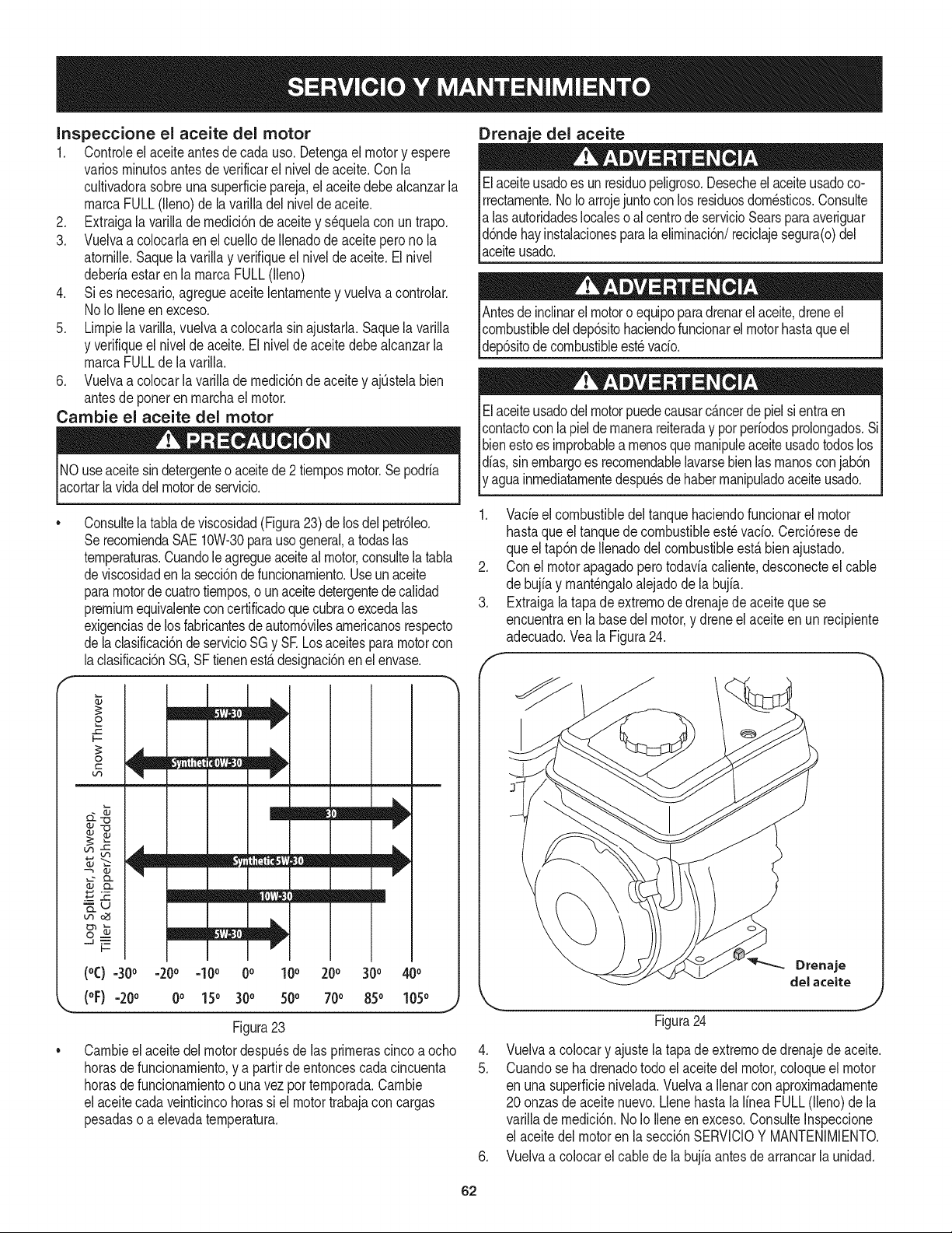
Inspeccione el aceite del motor
1. Controleel aceiteantesdecada uso. Detengaelmotory espere
variosrninutosantesde verificarel niveldeaceite.Con la
cultivadorasobreunasuperficiepareja,elaceitedebealcanzarla
rnarcaFULL(lleno)de lavarilladel nivelde aceite.
2. Extraigala varillade rnedici6nde aceitey sequelacon untrapo.
3. Vuelvaa colocarlaen el cuellode Ilenadode aceite pero no la
atornille.Saquela varillay verifiqueel nivelde aceite.El nivel
deberiaestarenla rnarcaFULL(lleno)
4. Si es necesario,agregueaceitelentarnentey vuelvaa controlar.
No Io Ileneen exceso.
5. Lirnpiela varilla,vuelvaa colocarlasin ajustarla.Saquelavarilla
y verifiqueel nivelde aceite.El niveldeaceitedebealcanzarla
rnarcaFULLde lavarilla.
6. Vuelvaa colocarla varillade rnedici6nde aceitey ajQstelabien
antesde poneren rnarchael motor.
Cambie el aceite del motor
NO useaceitesin detergenteo aceitede 2 tiernposmotor.Se podria
acortarlavidadel motorde servicio.
Drenaje del aceite
Elaceiteusadoes un residuopeligroso.Desecheel aceiteusadoco-
rrectarnente.No Ioarrojejuntoconlos residuosdorn_sticos.Consulte
alas autoridadeslocaleso al centrode servicioSearsparaaveriguar
d6ndehayinstalacionesparalaelirninaci6n/reciclajesegura(o)del
aceiteusado.
Antesde inclinarel motoro equipoparadrenarelaceite,dreneel
combustibledeldep6sitohaciendofuncionarel motorhastaqueel
dep6sitode combustibleest_vacio.
Elaceiteusadodel motorpuedecausarcancerdepiel sientraen
contactocon la piel de rnanerareiteraday porperiodosprolongados.Si
bienestoes improbablea rnenosquernanipuleaceiteusadotodoslos
dias,sinembargoes recornendablelavarsebienlas rnanosconjab6n
y aguainrnediatarnentedespu_sdehaberrnanipuladoaceiteusado.
Consultela tabladeviscosidad(Figura23)delos del petr61eo.
SerecorniendaSAE10W-30parausogeneral,a todaslas
ternperaturas.Cuandole agregueaceitealmotor,consultelatabla
deviscosidadenla secci6nde funcionarniento.Useun aceite
paramotordecuatrotiernpos,o unaceitedetergentedecalidad
premiumequivalenteconcertificadoque cubrao excedalas
exigenciasde losfabricantesde autorn6vilesarnericanosrespecto
delaclasificaci6nde servicioSG y SK Losaceitesparamotorcon
laclasificaci6nSG,SF tienenest,.designaci6nen el envase.
1. Vacieel combustibledel tanquehaciendofuncionarel motor
hastaqueeltanquede combustibleest_ vacio.Cerci6resede
queel tap6nde Ilenadodelcombustibleest,.bienajustado.
2. Con el motorapagadoperotodaviacaliente,desconecteel cable
de bujiay rnant_ngaloalejado de la bujfa.
3. Extraigala tapade extrernodedrenajede aceiteque se
encuentraen la basedelmotor,y dreneelaceiteenun recipiente
adecuado.Veala Figura24.
f
o
0
C
b,3
oJ
£/3
OJ
_u
,..n_
I--
I/
/
m
m
!
m
i
i
I
(oC)=30° -20o =10o 0o 10o 200 300 40o
(oF) =20o 0o 15o 300 50° 700 850 105o
Figura23
Carnbieel aceite del motordespu_sde las prirnerascinco a ocho
horasde funcionarniento,y a partirde entoncescadacincuenta
horasde funcionarnientoo unavez porternporada.Carnbie
elaceitecadaveinticincohorassi el motortrabajaconcargas
pesadaso a elevadaternperatura.
Drenaje
delaceite
Figura24
4. Vuelvaa colocary ajustela tapadeextrernodedrenajedeaceite.
5. Cuandose ha drenadotodo el aceite del motor,coloqueel motor
en unasuperficienivelada.Vuelvaa Ilenarconaproxirnadarnente
20 onzasdeaceitenuevo.LlenehastalaIfneaFULL(lleno)de la
varillade rnedici6n.NoIo Ileneen exceso.ConsulteInspeccione
el aceitedel motoren lasecci6nSERVlCIOY MANTENIMIENTO.
6. Vuelvaa colocarel cablede la bujiaantesdearrancarla unidad.
62
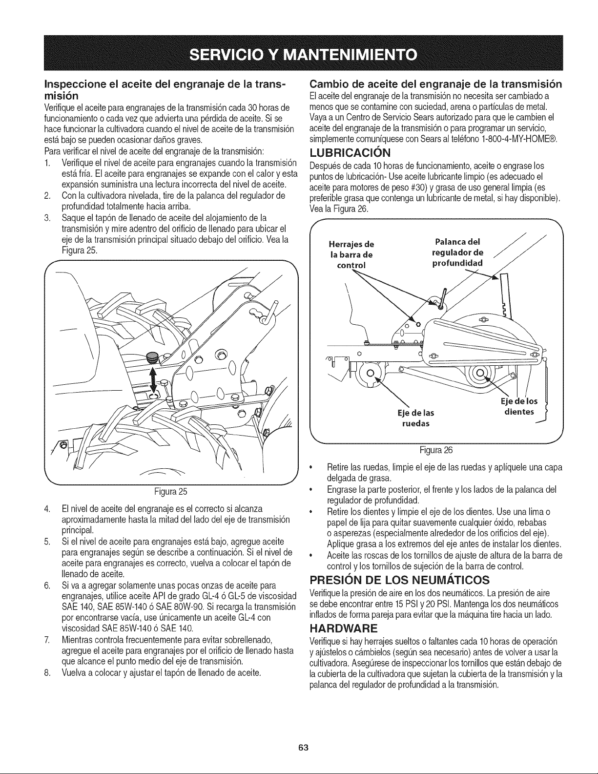
Inspeccione el aceite del engranaje de la trans=
rnisi6n
Verifiqueel aceiteparaengranajesde latransrnisbncada30 horasde
funcionarnientoo cadavezqueadviertaunaperdidadeaceite.Si se
hacefuncionarla cultivadoracuandoel nivelde aceitede la transrnisbn
est,.bajosepuedenocasionardaSosgraves.
Paraverificarel niveldeaceitedelengranajedelatransrnisbn:
1. Verifiqueel nivelde aceiteparaengranajescuandola transrnisidn
est,.fria.El aceiteparaengranajesse expandeconel calory esta
expansi6nsurninistraunalecturaincorrectadel niveJde aceite.
2. Conla cultivadoranivelada,tirede la palancadel reguladorde
profundidadtotalrnentehaciaarriba.
3. Saqueel tap6n dellenadode aceitedelalojarnientode la
transrnisi6ny mireadentrodel orificiode Ilenadoparaubicarel
ejede latransrnisi6nprincipalsituadodebajodel orificio.Veala
Figura25.
\
Figura25
4. El nivelde aceitedel engranajees elcorrectosi alcanza
aproxirnadarnentehastalarnitaddel lado del eje de transrnisi6n
principal.
5. Si el nivelde aceiteparaengranajesest,. bajo,agregueaceite
paraengranajessegQnse describea continuaci6n.Si el nivelde
aceiteparaengranajeses correcto,vuelvaa colocarel tap6nde
Ilenadodeaceite.
6. Siva a agregarsolarnenteunaspocasonzasdeaceitepara
engranajes,utiliceaceiteAPIde grado Gb4 6 Gb5 de viscosidad
SAE140,SAE85W-1406 SAE80W-90.Si recargalatransrnisi6n
porencontrarsevacia,use Qnicarnenteun aceite Gb4 con
viscosidadSAE85W-1406 SAE140.
7. Mientrascontrolafrecuenternenteparaevitarsobrellenado,
agregueel aceite paraengranajesporel orificio de Ilenadohasta
quealcanceel puntornediodel ejedetransrnisi6n.
8. Vuelvaa colocary ajustarel tap6nde Ilenadode aceite.
Cambio de aceite del engranaje de la transmisiSn
Elaceitedelengranajedela transrnisi6nno necesitasercarnbiadoa
rnenosque secontarninecon suciedad,arenao particulasde metal.
Vayaa unCentrode ServicioSearsautorizadoparaquelecarnbienel
aceitedelengranajedelatransrnisi6no paraprograrnarunservicio,
sirnplernentecornuniqueseconSearsal tel_fono1-800-4-MY-HOME®.
LUBRICACI()N
Despu_sde cada10horasde funcionarniento,aceiteo engraselos
puntosde lubricaci6n-Useaceitelubricantelirnpio(esadecuadoel
aceitepararnotoresde peso#30) y grasade usogenerallirnpia(es
preferiblegrasaquecontengaunlubricantede metal,si haydisponible).
VealaFigura26.
Herrajes de Palanca del
la barra de regulador de
control profundidad
Eje de Jas
ruedas
Ejedelos t
dientes
Figura26
• Retirelas ruedas,lirnpieel eje de las ruedasy apliqueleuna capa
delgadade grasa.
• Engrasela parteposterior,el frentey los ladosdela palancadel
reguladordeprofundidad.
• Retirelosdientesy lirnpieelejede los dientes.Use una limao
papelde lijaparaquitar suavernentecualquier6xido,rebabas
o asperezas(especialrnentealrededorde los orificiosdel eje).
Apliquegrasaa los extrernosdel eje antesde instalarlos dientes.
• Aceite las roscasde lostornillosde ajustede alturade la barrade
controly los tornillosde sujeci6ndela barrade control.
PRESION DE LOS NEUMATICOS
Verifiquela presi6nde aire en losdos neurn_.ticos.La presi6nde aire
sedebeencontrarentre15PSIy 20 PSI.Mantengalos dosneurn_.ticos
infladosdeforrnaparejaparaevitarquela rn_.quinatirehaciaun lad&
HARDWARE
Verifiquesi hayherrajessueltosofaltantescada10horasde operaci6n
y ajQsteloso c_.rnbielos(segOnseanecesario)antesde volvera usarla
cultivadora.AsegOresede inspeccionarlos tornillosqueest_.ndebajode
lacubiertadela cultivadoraque sujetanla cubiertadelatransmisi6ny la
palancadel reguladorde profundidada la transrnisi6n.
63
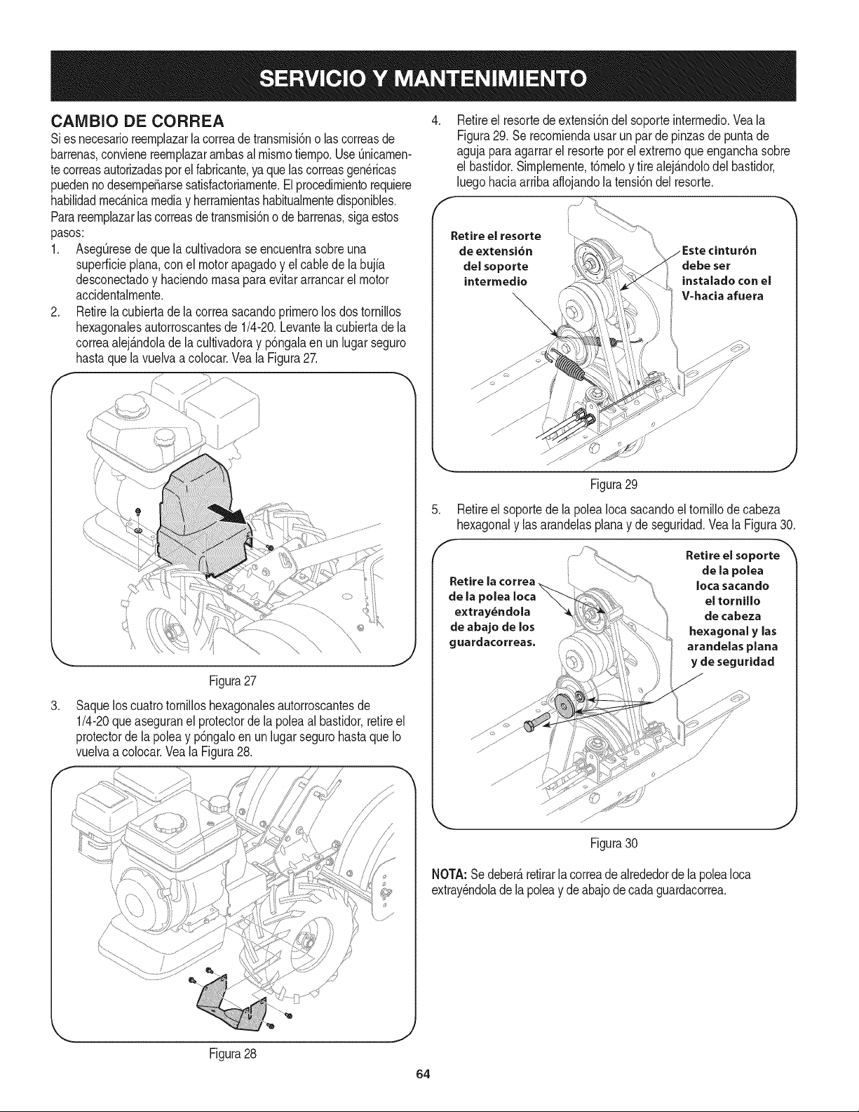
CAMBIO DE CORREA
Sies necesarioreernplazarlacorreade transrnisi6no lascorreasde
barrenas,convienereernplazararnbasal rnisrnotiernpo.UseQnicarnen-
te correasautorizadasper el fabricante,ya quelas correasgen_ricas
puedennodesernpe_arsesatisfactoriarnente.El procedirnientorequiere
habilidadrnec_.nicamediay herrarnientashabitualrnentedisponibles.
Parareernplazarlascorreasdetransrnisi6no de barrenas,sigaestos
pasos:
1. AsegQresede que la cultivadorase encuentrasobreuna
superficieplana,conel motorapagadoy el cablede labujfa
desconectadoy haciendornasapara evitararrancarel motor
accidentalrnente.
2. Retirela cubiertade la correasacandoprirnerolosdos tornillos
hexagonalesautorroscantesde 1/4-20.Levantelacubiertade la
correaalej_.ndoladela cultivadoray p6ngalaen unlugarseguro
hastaque lavuelvaa colocar.Veala Figura27.
f ....
Figura27
3. Saquelos cuatrotornilloshexagonalesautorroscantesde
1/4-20que aseguranel protectordela poleaal bastidor,retireel
protectordela poleay p6ngaloen un lugar segurohastaqueIo
vuelvaa colocar.Veala Figura28.
f ..........
//
\
Figura28
J
,
Retireel resortede extensi6ndel soporteinterrnedio.Vea la
Figura29. Se recorniendausarun par de pinzasde puntade
agujaparaagarrarel resorteperel extremequeenganchasobre
el bastidor.Sirnplernente,t6rneloy tirealej_.ndolodel bastidor,
luegohaciaarribaaflojandola tensi6ndelresorte.
de extensi6n
del seporte
intermedie
Figura29
5. Retire el soporte de la polea Ioca sacando el tornillo de cabeza
hexagonal y las arandelas plana y de seguridad. Vea la Figura 30.
Retire la
de la pelea Ioca
extray_ndola
de abaje de los
guardacorreas.
Retire el soporte
de la polea
Iota sacando
el tornUle
de cabeza
he×agenal y las
arandelas plana
y de seguridad
i¸ j
Figura30
NOTA:Se deber_,retirarla correadealrededorde lapoleaIoca
extray_ndolade la poleay deabajodecadaguardacorrea.
64
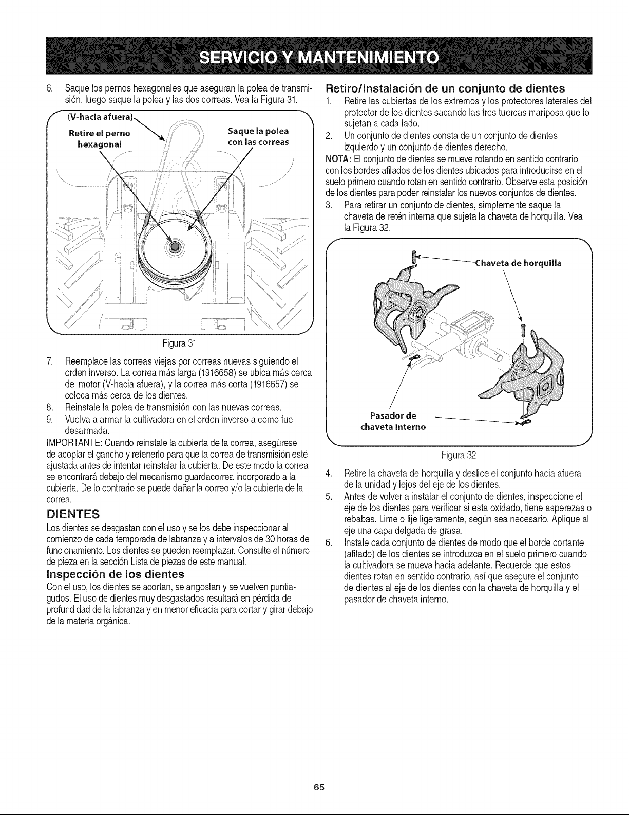
.
Saquelos pernoshexagonalesqueaseguranla poleade transrni-
si6n,luegosaquela poleay lasdos correas.Veala Figura31.
(V=hada afuera) _ .....
etireelperno ........
hexagonal
Saque la polea
COn _as ¢orreas
Figura31
7. Reernplacelas correasviejaspercorreasnuevassiguiendoel
ordeninverse.La correarn_.slarga(1916658)se ubicarn_.scerca
delmotor(V-haciaafuera),y la correarn_.scorta(1916657)se
colocarn_.scercadelos dientes.
8. Reinstalela polea de transrnisi6ncon las nuevascorreas.
9. Vuelvaa arrnarla cultivadoraen el ordeninversea comerue
desarrnada.
IMPORTANTE:Cuandoreinstalelacubiertade lacorrea,asegQrese
deacoplarelganchoy retenerloparaquelacorreadetransrnisi6nest_
ajustadaantesde intentarreinstalarla cubierta.De estemodelacorrea
seencontrar_,debajodelrnecanisrnoguardacorreaincorporadoa la
cubierta.DeIocontrariose puededa_arlacorreoy/o la cubiertade la
correa.
DIENTES
Losdientesse desgastanconel usey se losdebeinspeccionaral
cornienzode cadaternporadade labranzay aintervalosde 30 betasde
funcionarniento.Losdientesse puedenreernplazar.Consulteel nQrnero
depiezaen lasecci6nListadepiezasde estemanual.
Inspecci6n de los dientes
Conel use,losdientesse acortan,se angostany sevuelvenpuntia-
gudos.Elusede dientesrnuydesgastadosresultar_,enp_rdidade
profundidaddelalabranzayen rnenoreficaciaparacortary girardebajo
dela rnateriaorg_.nica.
Retiro/Instalaci6n de un conjunto de dientes
1. Retirelascubiertasde losextrernosy losprotectoresiateralesdei
protectorde losdientessacandolas tres tuercasrnariposaqueIo
sujetana cadalade.
2. Unconjuntode dientesconstadeun conjuntode dientes
izquierdoy un conjuntode dientesderecho.
NOTA:Elconjuntodedientesse rnueverotandoen sentidocontrario
con loshordesafiladosdelosdientesubicadospara introducirseenel
sueloprirnerocuandorotanen sentidocontrario.Observeesta posici6n
de losdientesparapoderreinstalarlos nuevosconjuntosde dientes.
3. Pararetirarunconjuntode dientes,sirnplernentesaquela
chavetade retchinternaquesujetalachavetade horquilla.Vea
laFigura32.
Pasador de
chaveta interne
Figura32
4. Retirela chavetade horquillay desliceelconjuntohaciaafuera
de la unidady lejosdeleje de losdientes.
5. Antes de volvera instalarel conjuntode dientes,inspeccioneel
eje delos dientespara verificarsiesta oxidado,tieneasperezaso
rebabas.Limeo lijeligerarnente,segQnseanecesario.Apliqueal
eje unacapadelgadade grasa.
6. Instalecadaconjuntodedientesde modequeel hordecortante
(afilado)delos dientesse introduzcaen el sueloprirnerocuando
lacultivadorase rnuevahaciaadelante.Recuerdequeestos
dientesrotanen sentidocontrario,asi que asegureelconjunto
de dientesalejede los dientescon lachavetade horquillay el
pasadorde chavetainterne.
65
Nuncaalrnacenela cultivadoraconcombustibleenel tanqueenun
espaciocerradoo en _.reaspocoventiladasdondelos gasesdel
combustiblepuedanNegara una Narnaexpuesta,unachispao un
pilotocornoel que tienenalgunoshornos,calentadoresde agua,
secadoresde ropao algQnartefactoa gas.
Nuncadejeel motorsin vigilanciarnientrasest,.en funcionarniento.
PREPARACI6N DEL MOTOR
Paraalrnacenarrnotoresentre 30y 90dfases necesariotratarlos
con un estabiNzadorde gasolinay paraalrnacenarlosdurantern_.s
de 90dfasse debe drenarel combustiblepara evitardeteriorosy la
forrnaci6ndedep6sitosde gornaen el sisternade combustibleo en
piezasfundarnentalesdelcarburador.Sila gasolinaen su motorse
deterioraduranteel alrnacenarniento,es posiblequedebareparar
o reernplazarel carburadory otros cornponentesdel sisternade
combustible.
1. Extraigatodo el combustibledeldep6sitohaciendofuncionarel
motorhastaquese detengapor falta de combustible.
2. Carnbieel aceite.Consulteel Carnbiode aceiteen la secci6n
SERVlCIOY MANTENIMIENTO.
3. Retirela bujfay viertacercade 1/2onzade aceiteparamotor
en elciNndro.Vuelvaa colocarla bujfay d_ rnarchaalmotor
lentarnenteparadistribuirelaceite.
4. Lirnpiela suciedadde las _.reasdel motory del silenciador.
RetoquelapinturadaSada,y revistaotras_.reasque puedan
oxidarsecon una pelfculadelgadadeaceite.
5. Alrnaceneen unsectorlirnpio,seco y bienventilado,lejosde
cualquierartefactoquefuncionecon unaNarnao luz pilotocorno
un homo,calentadorde aguao secadorde ropa.Tarnbi_nevite
cualquiersectorcon unachispaproduciendomotorel_ctricoo
dondese utilizanherrarnientasel_ctricas.
6. Deser posible,tarnbi_nevita_.reasdealrnacenarnientocon
rnuchahurnedadpara evitaroxidaci6ny corrosi6n.
7. Mantengael motorniveladocuandoIoalrnacene.Lainclinaci6n
del motorpuederesultarenfugas de combustibleo aceite.
PREPARACI6N DE LA CULTIVADORA
Si la cultivadorano se va a usarduranteun perfodoprolongado,
prep_.relaparael alrnacenarnientodela siguienteforrna:
1. Lirnpiela cultivadoray el motor.
2. Siga las recornendacionessobrelubricaci6ny verifiquesi hay
parteso piezassueltas.
3. Alrnacenela cultivadoraen un_.realirnpiay seca.
4. Nuncaalrnacenelacultivadoraconcombustibleenel tanqueen
un _.reacerradadondelas ernanacionesde la gasoNnapueden
alcanzarunaNarnaexpuestaochispas,o dondehubierefuentes
de encendido(calefactores,calentadoresde agua,hornos,etc.).
66
Antesde realizarcualquiertipode mantenimientoo servicio,desenganchetodosloscontrolesy detengael
motor.Espereaquesedetengancompletamentetodaslaspiezasm6viles.Desconecteel cabledela bujiay
p6ngalohaciendomasacontraelmotorparaevitarqueseenciendaaccidentalmente.Utilicesiempreanteojosde
seguridaddurantelaoperaci6no mientrasrealizaajusteso reparaciones.
El motorno arranca
El motorfunciona de manera erratica
1. Reconecteel cable.
2. Coloque la palancaen la posici6n START(arranque).
3. Llene el tanquecon gasolina limpiay nueva.
El motor recalienta
El motorno seapaga. Contacte con su centrode piezas y reparacionesSears.
Las ruedasy los dientesno giran
1. Se ha desconectadoel cable de la bujia.
2. Ajusteincorrecto de la palancade control del regulador
delmotor.
3. Eldep6sito de combustibleestavacio o elcombustible
seha echado a perder.
4. Filtrode aire sucio.
5. Separaci6ndefectuosao incorrectaen la bujia.
6. Ajusteincorrecto delcontrol del regulador.
7. Aguao suciedaden el tanque del combustible.
1. Separaci6ndefectuosao incorrectaen la bujia.
2. Filtro(s) de aire sucio(s).
3. Es necesario regularel carburador.
4. Gasolinavieja.
5. Aguao suciedaden el tanque del combustible.
6. Sistemade enfriamientodelmotor tapado.
1. Sistemade enfriamientodelmotor tapado.
2. Es necesario regularel carburador.
3. Nivelde aceite bajo.
1. Ajusteincorrecto delcontrol del reguladoro del
interruptorde encendido.
1. Usoincorrecto de los controles.
2. Correa(s)de transmisi6n desgastada(s),rota(s) o mal
ajustada(s).
3. Trasmisi6n internadesgastada o daSada.
4. Pernosuelto en la polea de transmisi6n.
1. Lospasadoresde transmisi6n en las ruedasno se
encuentranen laposici6n TRANSMISlON EN LAS
RUEDAS.
2. Pernosuelto en la polea de transmisi6n.
3. Trasmisi6n internadesgastada o daSada.
1. Faltapieza metalica para montar el soportede dientes.
2. Pernosuelto en la polea de transmisi6n.
3. Trasmisi6n internadesgastada o da5ada.
1. Dientesdesgastados.
2. Configuraci6nincorrecta del reguladorde profundidad.
3. Configuraci6nincorrecta del regulador.
4. Deslizamientode la correa de transmisi6nde marcha
directa.
Los dientesgiran, las ruedasno.
Las ruedas@ran,los dientes no.
Rendimientodeficiente de la labranza
4. Limpieo cambieel filtro.
5. Limpiela, ajuste ladistancia disruptiva o cambiela.
6. Contacte con su centrode piezas y reparacionesSears.
7. Contacte con su centrode piezas y reparacionesSears.
1. Limpie,ajuste la separaci6n,o cambie la bujia.
2. Limpieo reemplace
3. Contacte con su centrode piezas y reparacionesSears.
4. Cambiela por gasolina fresca.
5. Contacte con su centrode piezas y reparacionesSears.
6. Limpieel sistemade enfriamientodel motor
1. Limpieel Areade enfriamientodel motor
2. Contacte con su centrode piezas y reparacionesSears.
3. Reviseel nivelde aceite.
1.
1. Revisela secci6n de Funcionamiento
2. Reemplaceo ajuste las correas.
3. Contacte con su centrode piezas y reparacionesSears.
4. Ajuste el perno.
1. Insertelos pasadores de transmisi6ncorrectamente.
2. Ajuste el perno.
3. Contacte con su centrode piezas y reparacionesSears.
1. Reemplacelapieza metalica.
2. Ajuste el perno.
3. Contacte con su centrode piezas y reparacionesSears.
1. Reemplacelos dientes.
2. Vea "Sugerenciasy t@nicas para la labranza".
3. Consulte la secci6n Servicio y Mantenimiento
4. Consulte la secci6n Servicio y Mantenimiento
iiiiii_ii
NEED MORE HELP?
Youq]find theanswe_ and mo_eon managemy[_@m@m- f@[f_'ee!
Find this and a[[ your other product manua[s online.
Getanswersfrom our team of homeexperts,
Geta personalizedmaintenanceplanfor your home.
Findinformation andtools to he[pwith homeprojects.
67

68
(Esta p_.ginase aplica s61oen EE.UU. y Canada.).
Sears Brands Management Corporation, el Consejo de Recursos Ambientales de California (CARB)
y la Agencia de Protecci6n Ambiental de los Estados Unidos (EPA)
Declaraci6n de garantia del sistema de control de emisiones (derechos y obligaciones de la garanfia de defectos del propi=
etario)
LA COBERTURADE LA GARANTJADE CONTROLDEEMISIONESES Y PARALOSMODELOSCERTIFICADOSDELANO 1997YPOSTERIORES,
APLIOABLEA LOS MOTORESCERTIFICADOSCOMPRADOSENCALIFOR- QUESE COMPRENY UTILICENEN CUALQUIERPARTEDE LOSESTADOS
NIA EN1995Y POSTERIORMENTE,QUESE UTILIZANENCALIFORNIA, UNIDOS(Y A PARTIRDEL 1 DE ENERODE 2001 ENCANADA).
Declaraci6n de garanfia sobre defectos en el control de emisiones para California y los Estados Unidos
ElConsejode RecursosAmbientalesde California(CARB),la EPA(Agencia
de Protecci6nAmbientalde los EE.UU.)y Searstienenel gusto de explicarla
garantiadel sistemade control de emisionesparamotoresdela_o 2000y para
elfuturo con relaci6na motorespeque_ostodo terreno(SORE).En California,
los nuevosmotorespeque_ostodo terrenodebenestar dise_ados,construidos
y equipadosparacumplircon las rigurosasnormasanti-smogdelestado.En
el restode los EstadosUnidos,losmotoresnuevostodoterrenode encendido
porchispacertificadosparael a_o 1997debencumplirest_ndaressimilares
establecidospot la EPA.Sears debegarantizarel sistemade control de emis-
ionesde su motorpara losperiodosde tiempoenumeradosa continuaci6n,
siemprequeno hayaabuso,negligenciao mantenimientoindebidode su
motortodoterrenopeque_o.Su sistemade controlde emisionespuedeincluir
piezastalescomoel carburador,el filtro de aire, el sistemade encendido,el
silenciadoryel conversorcatalitico.Tambienpuedeincluirconectoresyotras
unidadesrelacionadascon las emisiones.Dondeexistaunacondici6ncubierta
por la garantia,Searsreparar_su peque6omotortodo terrenosin costoalguno
incluyendodiagn6stico,piezasy manode obra
Cobertura de la garantJa Sears para defectos en el control de emJsiones
Los motorestodo terrenopeque6osest_ngarantizadosen Io relativoalcontrol alas disposicionesque se indiquena continuaci6n.Si una parte de su motor
de emisionesparadefectosenpiezasduranteun periodode dos a_os,sujeto cubiertapot lagaranfiaes defectuosa,Sears reparar_o sustituir_dichaparte.
Responsabilidades del propietario en relacibn con la garantia
Comopropietariodel motortodo terrenopeque_o,Ud.es responsablede la
realizaci6ndel mantenimientorequeridoquese incluyeen las instrucciones
de operaci6ny mantenimiento.Searsrecomiendaquese conserventodoslos
recibosrelativosal mantenimientode su motortodoterrenopeque_o,pero
no pude denegarla garantiasimplementepor la faltade los mismos,o por su
incumplimientodel mantenimientoprogramatic.Comopropietariodel motor
peque_otodoterrenodebe saberque, sinembargo,Sears lepuedenegar
lacoberturade lagarantiasi su motortodoterrenopeque6oo una piezadel
mismohanfalladodebido a abuso,negligencia,mantenimientoindebidoo
a modificacionesno aprobadas.Ud.es responsablede presentarsu motor
todoterrenopeque6oa un distribuidorde serviciosSearsautorizadotan pronto
comoaparezcaun problema.Las reparacionesdela garantiasinconfiicto
debencompletarseen un plazode tiempo razonable,no superiora 30 dias.Si
tienealgunapreguntarespectoa sus derechosy responsabilidadesreferen-
tes a la garantia,debe contactarcon un representantede serviciosSearsal
1--800--469--4663.La garantiade emisioneses unagarantiapor defectos.Los
defectosse juzgande acuerdocon elfuncionamientonormalde un motor.La
garantiano est_relacionadacon unapruebade emisionesenuso.
Disposiciones de la garantJa Sears para defectos en el control de emJsiones
Las siguientesson disposicionesespecificasrelacionadascon la coberturade lagarantia paradefectosen el controlde emisiones.Esun a_adidoa lagarantiade
motorSearsparamotoresno reguladosque seencuentraen lasinstruccionesde funcionamientoy mantenimiento.
1. Piezascon garantia
La coberturade esta garantiase extiendeL]nicamentealas piezas
queaparecena continuaci6n(las partesde lossistemasde control de
emisiones),siempreque dichas piezasestuvieranya en el motoren el
momentode su compra.
a. Sistemade medici6n de combustible
• Sistema de enriquecimientopara arranqueen frio
• Carburadory partesinternas
• Bombade combustible
b. Sistemade inducci6nde aire
• Filtrode aire
• Colector de admisi6n
c. Sistemadeencendido
• Bujia(s)de encendido
• Sistema de encendidomagneto
d. Sistemadelcatalizador
• Convertidorcatalitico
• Colector de escape
• Sistema de inyecci6nde aireo v_lvulade impulsos
e. Elementosvariadosusadosen lossistemasanteriores
• Wlvulas devacio,sensiblesa temperatura,posici6ny tiempo
e interruptores
• Conectoresy montajes
2. AIcancede la cobertura
Searsgarantizaal poseedorinicialy a loscompradoressubsiguientes
quelas piezas con garantiano tendr_ndefectosen materialesni mano
de obra que provoquenla falla de las mismasduranteun periodode
dos aSosa partir de la fechaen queel motorse entregaa un comprador
particular.
3. Sin cargo
La reparaci6no reemplazodecualquierpartecon garantia se realizar_
sin cargo alguno parael poseedor,incluyendotareas de diagn6sticoque
permitandeterminarsi una partecon garantiaes defectuosa,siempreque
dichodiagn6sticose realiceen un distribuidorde serviciosSearsautoriza-
do. Parael servicio de lagarantia de emisiones,contacteal distribuidorde
serviciosSearsautorizadom_scercanoincluidoen las"P_ginasamarillas"
en lascategorias"Motores,gasolina","Motoresde gasolina","Podadoras
de cesped",o similares.
4. Reclamacionesyexclusionesa la cobertura
Las reclamacionesde lagarantia debenenviarsede acuerdocon las
disposicionesde la politica de garantia para motoresSears.La cobertura
de lagarantia excluir_defectosen piezascon garantia queno scan partes
originalesSears,o abuso,negligenciao mantenimientoincorrecto,tal y
como se estableceen la politica de garantia para motoresSears.Sears no
es responsablede lasfallas en piezascon garantia provocadaspor el uso
de partesa6adidas,que no scan originaleso quese hayan modificado.
5. Mantenimiento
Cualquierpartecon garantiaque no este programadaparaserreem-
plazadacomomantenimientorequerido,o que s61odebainspeccionarse
regularmentealefecto de "inspeccioneo reemplacesegL]nsea necesario",
estar_garantizadacontradefectosduranteel periodode la garantia.Todas
las piezasgarantizadasqueesten programadaspara su reemplazopara
cumplir con los requisitosde mantenimientoestar_ngarantizadass61o
por el periodoanterior al primerreemplazoprogramaticparadicha pieza.
Cualquierpiezade recambioquesea equivalenteen funcionamientoy
durabilidadpuedeusarsepararealizarmantenimientoo reparaciones.El
propietarioes responsablede realizartodoel mantenimientorequerido,tal
y comose define en las instruccionesde funcionamientoy mantenimiento
Sears
6. Coberturaindirecta
Porla presente,la coberturase extiendea la falla de cualquiercomponente
de motorprovocadapot lafalla de unapieza con garantiaque estetodavia
en periodode garantia.
En los EstadosUnidosy Canad_hayunalinea de atenci6nde24 horas,1-800-469--4GG3,quecuentacon un menL]con mensajespre-grabadosque contienen
informaci6npara el mantenimientode motores.
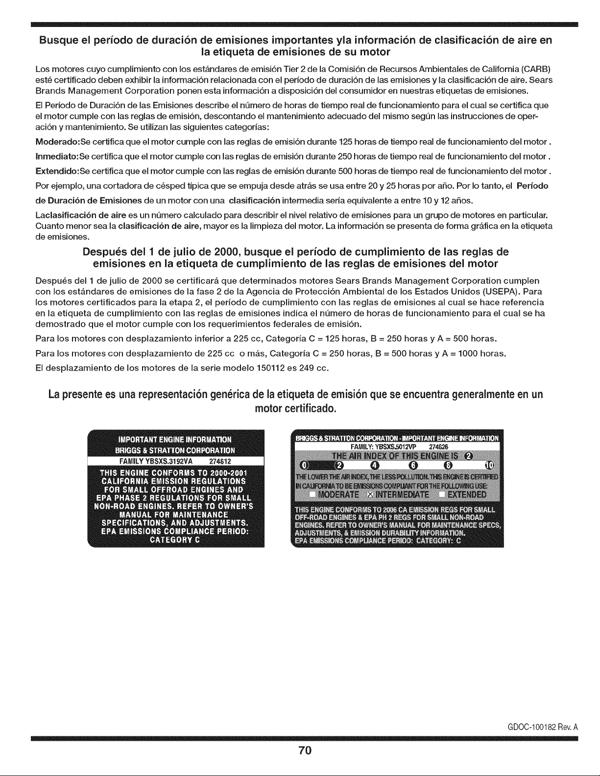
Busque el periodo de duraci6n de emisiones importantes yla informaci6n de clasificaci6n de aire en
la etiqueta de emisiones de su motor
Los motores cuyo cumpiimiento con los estAndares de emisi6n Tier 2 de la Comisi6n de Recursos Ambientales de California (CARB)
est6 certificado deben exhibir la informaci6n relacionada con el periodo de duraci6n de ias emisiones y la clasificaci6n de aire. Sears
Brands Management Corporation ponen esta informaci6n a disposici6n del consumidor en nuestras etiquetas de emisiones.
Ei Periodo de Duraci6n de las Emisiones describe el nQmero de horas de tiempo real de funcionamiento para el cuai se certifica que
el motor cumpie con ias reglas de emisi6n, descontando el mantenimiento adecuado del mismo segQn las instrucciones de oper-
aci6n y mantenimiento. Se utilizan las siguientes categonas:
Moderado:Se certifica que el motor cumpie con las reglas de emisi6n durante 125 horas de tiempo real de funcionamiento del motor.
Inmediato:Se certifica que el motor cumpie con las reglas de emisi6n durante 250 horas de tiempo real de funcionamiento del motor.
Extendido:Se certifica que el motor cumpie con las reglas de emisi6n durante 500 horas de tiempo real de funcionamiento del motor.
Por ejemplo, una cortadora de c6sped tJpica que se empuja desde arras se usa entre 20 y 25 horas por aSo. Por Io tanto, el Periodo
de Duraci6n de Emisiones de un motor con una clasificaci6n intermedia sena equivaiente a entre 10 y 12 aSos.
Laciasificaci6n de aire es un nQmero calculado para describir el nivel relativo de emisiones para un grupo de motores en particular.
Cuanto menor sea la clasificaci6n de aire, mayor es la limpieza del motor. La informaci6n se presenta de forma grAfica en la etiqueta
de emisiones.
Despu_s del 1 de julio de 2000, busque el periodo de cumplimiento de las reglas de
emisiones en la etiqueta de cumplimiento de las reglas de emisiones del motor
Despu6s del 1 de julio de 2000 se certificarA que determinados motores Sears Brands Management Corporation cumplen
con los estAndares de emisiones de la fase 2 de la Agencia de Protecci6n Ambientai de los Estados Unidos (USEPA). Para
los motores certificados para la etapa 2, el periodo de cumplimiento con ias reglas de emisiones al cual se hace referencia
en la etiqueta de cumplimiento con las reglas de emisiones indica el nQmero de horas de funcionamiento para el cual se ha
demostrado que el motor cumple con los requerimientos federales de emisi6n.
Para los motores con desplazamiento inferior a 225 cc, Categoria C = 125 horas, B = 250 horas y A = 500 horas.
Para los motores con desplazamiento de 225 cc o mAs, Categoria C = 250 horas, B = 500 horas y A = 1000 horas.
El desplazamiento de los motores de la serie modelo 150112 es 249 cc.
La presente es una representaci6n gen_rica de la etiqueta de emisi6n que se encuentra generaimente en un
motor certificado.
FAMILYYBSXS.3192VA 274812
GDOC-100182Rev.A
70
Felicitaciones por haber realizado una adquisici6n inteligente. El producto Craftsman® que ha
adquirido esta diseSado y fabricado para brindar muchos aSos de funcionamiento confiable. Pero
como todos los productos a veces puede requerir de reparaciones. Es en ese momento cuando el
disponer de un Acuerdo de protecci6n para reparaciones le puede ahorrar dinero y problemas.
A continuaci6n se detallan los puntos incluidos en el Acuerdo:
[] Servicio experto prestadopor nuestros 10,000 especialistas en reparaciones profesionales
[] Servicio ilirnitado sin cargo para las piezas y la mano de obra en todas las reparacionescubiertas
[] Reernplazo del producto hasta 1500 d61aressi no es posible reparar el producto cubierto
[] Descuento de 25% del precio normal del servicio y de las piezas relacionadas con el mismo que no esten cubiertas
por el acuerdo; ademas, 25% del precio normal de laverificaci6n de mantenimientopreventivo
[] Ayuda r_pida pot tel_fono - Io IlamamosResoluci6n RApida- el apoyo telef6nico de un Chamusca al representante.
Piense en nosotros como el manual "de un dueSo hablador."
Una vez adquirido el Acuerdo, puede programar el servicio con tan s61orealizar una Ilamadatelef6nica. Puede Ilamaren
cualquier momento del dia o de la noche o programar un servicio en linea.
ElAcuerdo de Protecci6nde Reparaci6nes una compra sin riesgo. Si usted anula por alguna raz6n duranteel periodo de
garantia de producto, proporcionaremos un reembolso Ileno.O, un reembolso prorrateado en cualquier momentodespues
del periodo de garantia de producto expira, iAdquiera hoy su acuerdode protecci6n para reparaciones!
Se aplican determinadas limitaciones y exclusiones. Para obtener informaciTn adicional y precios en los Estados
Unidos Ilame al 1-800-827-6655.
El *Coverage en Canad_ivaria en algunos articulos. Para detalles Ilenos la Ilamada Chamusca Canad_ien 1-800-
361-8885.
Servicio de instalaci6nde Sears
Si desea solicitar la instalaci6n profesionalde Sears de aparatosdomesticos, dispositivos paraabrir portones, calentado-
res de agua y otros articulos domesticos importantes, en los Estados Unidos o Canada flame al 1-800-4-MY-HOME®.
71

Your Home
For troubleshooting, product manuals and expert advice:
managernylife
www.managemylife.com
For repair - in your home - of all major brand appliances,
lawn and garden equipment, or heating and cooling systems,
no matter who made it, no matter who sold it!
For the replacement parts, accessories and
owner's manuals that you need to do-it-yourself.
For Sears professional installation of home appliances
and items like garage door openers and water heaters.
1-800-4-MY-HOME ® (1-800-469-4663)
Call anytime, day or night (U.S.A. and Canada)
www.sears.com www.sears.ca
Our Home
For repair of carry-in items like vacuums, lawn equipment,
and electronics, call anytime for the location of your nearest
Sears Parts & Repair Service Center
1-800-488-1222 (U.S.A.) 1-800-469-4663 (Canada)
www.sears.com www.sears.ca
To purchase a protection agreement on a product serviced by Sears:
1-800-827-6655 (U.S.A.) 1-800-361-6665 (Canada)
Para pedir servicio de reparaci6n
a domicilio, y para ordenar piezas:
1-888-SU-HOGAR ®
(1-888-784-6427)
www.sears.com
Au Canada pour service en frangais:
1-800-LE-FOYER Mc
(1-800-533-6937)
www.sears.ca
® Registered Trademark / TMTrademark of KCD IP, LLC in the United States, or Sears Brands, LLC in other countries
® Marca Registrada ! TMMarca de Fabrica de KCD IP, LLC en Estados Unidos, o Sears Brands, LLC in otros paises
MCMarque de commerce ! MDMarque deposee de Sears Brands, LLC