
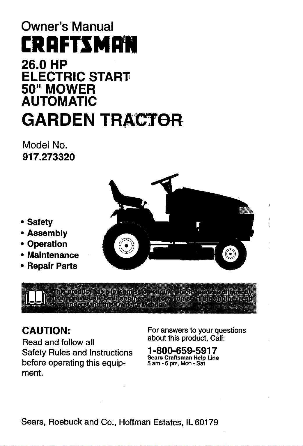
Owner's Manual
CRAFTSMI I!
26.0 HP
ELECTRIC STAR_
50" MOWER
AUTOMATIC
GARDEN TRACTOR
Model No.
917.273320
• Safety
• Assembly
• Operation
• Maintenance
• Repair Parts
CAUTION:
Read and follow all
Safety Rules and Instructions
before operating this equip-
ment.
For answers to your questions
about thisproduct, Call:
1-800-659-5917
Sears Craftsman Help Line
5 am - 5 pm, Mon- Sat
Sears, Roebuck and Co, Hoffman Estates, IL 60179
Warranty ................................................. 2
Safety Rules........................................... 2
Product Specifications ........................... 5
Assembly................................................ 8
Operation.............................................. 12
Maintenance Schedule......................... 19
Maintenance ......................................... 19
Service and Adjustments...................... 23
Storage ................................................. 31
Troubleshooting.................................... 32
Repair Pads ......................................... 36
Parts Ordering ....................... Back Cover
LIMITED TWO YEAR WARRANTY ON CRAFTSMAN RIDING EQUIPMENT
For two (2) years from the date of purchase, ifthis Craftsman Riding Equipment ismain-
tained, lubricated and tuned up accordingto the instructionsin the owner's manual,
Sears will repair or replace, free ofcharge, any parts found to be defective in material or
workmanship.
This Warranty does notcover:.
• Expendable items which become wom during normal use, such as blades, spark
plugs, air cleaners, belts, etc.
• Tire replacement or repair caused by puncturesfrom outside objects, such as nails,
thorns, stumps, or glass.
• Repairs necessary because of operator abuse, negligence, improper storage or acci-
dent or the failure to maintain the equipment accordingto the instructionscontained in
the owner's manual.
• Riding equipment used for commercial or rental purposes.
LIMITED 90 DAY WARRANTY ON BA'I-I'ERY
For ninety (90) days from date of purchase, if any battery included with this riding equip-
ment proves defective in material or workmanship and our testing determines the bat-
tery will not hold a charge, Sears will replace the battery at no charge. In-home warranty
service on your Craftsman riding equipment is available at no charge for 30 days from
the date of purchase. Please contact your nearest service center. After 30 days from the
date of purchase, wan;._nty service is available by taking your Craftsman riding equip-
ment to your nearest Sears Service Center. (In-home warranty service will still be avail-
able after 30 days from the date of purchase but a standard trip charge will apply). This
warranty applies only while this product is in the United States. This Warranty gives you
specific legal rights, and you may also have other rights which may vary from state to
state.
Sears, Roebuck and Co., D/817 WA, Hoffman Estates, IL 60179
GENERAL OPERATION
• Read, understand, and follow all instruc-
tions in the manual and on the machine
before starting.
• Only allow responsible adults, who are
familiar with the instructions, to operate
the machine.
• Clear the area of objects such as rocks,
toys, wire, etc., which could be picked
up and thrown by the blade.
• Be sure the area is clear of other people
before mowing. Stop machine if anyone
enters the area.
• Never carry passengers.
• Do not mow in reverse unless absolute-
ly necessary. Always look down and
behind before and while backing.
• Be aware of the mower discharge direc-
tion and do not point it at anyone. Do
not operate the mower without either
the entire grass catcher or the guard in
place.
• Slow down before turning.
• Never leave a running machine unat-
tended. Always tum off blades, set park-
ing brake, stop engine, and remove
keys before dismounting.
2
• Tum off blades when not mowing.
• Stop engine before removing grass
catcher or unclogging chute.
• Mow only in daylight or good artificial
light.
• Do not operate the machine while under
"the influence of alcohol or drugs.
• Watch for traffic when operating near or
crossing roadways.
• Use extra care when loading or unload-
ing the machine into a trailer or track.
SLOPE OPERATION
Slopes are a major factor related to loss-
of-control and tipover accidents, which
can result in severe injury or death. All
slopes require extra caution. If you cannot
back up the slope or if you feel uneasy on
it, do not mow it.
DO:
• Mow up and down slopes, not across.
• Remove obstacles such as rocks, tree
limbs, etc.
• Watch for holes, ruts, or bumps. Uneven
terrain could overturn the machine. Tall
grass can hide obstacles.
• Use slow speed. Choose a low gear so
that you will not have to stop or shift
while on the slope.
• Follow the manufacturer's recommen-
dations for wheel weights or counter-
weights to improve stability.
• Use extra care with grass catchers or
other attachments. These can change
the stability of the machine.
• Keep all movement on the slopes slow
and gradual. Do not make sudden
changes in speed or direction.
• Avoid stading or stopping on a slope. If
tires lose traction, disengage the blades
and proceed slowly straight down the
slope.
DO NOT:
• Do notturn on slopes unless necessary,
and then, turn slowly and gradually
downhill, if possible.
• Do not mow near drop-otis, ditches, or
embankments. The mower could sud-
denly turn over if a wheel is over the
edge of a cliff or ditch, or if an edge
caves in.
• Do notmow on wet grass. Reduced
traction could cause sliding.
• Do nottry to stabilize the machine by
putting your foot on the ground.
• Do notuse grass catcher on steep
slopes.
CHILDREN
Tragic accidents can occur if the operator
is not alert to the presence of children.
Children are often attracted to the
machine and the mowing activity. Never
assume that children will remain where
you last saw them.
• Keep children out of the mowing area
and under the watchful care of another
responsible adult.
• Be alert and turn machine off if children
enter the area.
• Before and when backing, look behind
and down for small children.
• Never carry children. They may fall off
and be seriously injured or interfere with
safe machine operation.
• Never allow children to operate the
machine.
• Use extra care when approaching blind
comers, shrubs, trees, or other objects
that may obscure vision.
SERVICE
• Use extra care in handling gasoline and
other fuels. They are flammable and
vapors are explosive.
Use only an approved container.
Never remove gas cap or add fuel
with the engine running. Allow en-
gine to cool before refueling. Do not
smoke.
Never refuel the machine indoors.
Never store the machine or fuel
container inside where there is an
open flame, such as a water heater.
• Never run a machine inside a closed
area.
• Keep nuts and bolts, especially blade
attachment bolts, tight and keep equip-
meht in good condition.
• Never tamper with safety devices.
Check their proper operation regularly.
• Keep machine free of grass, leaves, or
other debris build-up. Clean oil or fuel
spillage. Allow machine to cool before
storing.
• Stop and inspect the equipment ifyou
strike an object. Repair, if necessary,
before restading.
3
• Never make adjustments or repairs with
the engine running.
• Grass catcher components are subject
towear, damage, and deterioration,
which could expose moving parts or
allow objects to be thrown. Frequently
check components and replace with
manufacturer's recommended parts,
when necessary.
• Mower blades are sharp and can cut.
Wrap the blade(s) or wear gloves, and
use extra caution when servicing them.
• Check brake operation frequently.
Adjustand service as required.
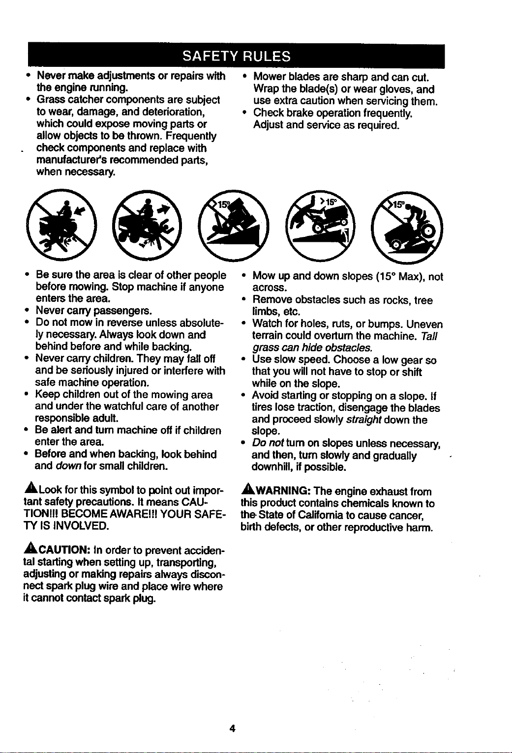
• Be sure the area is clear of other people • Mow up and down slopes (15 ° Max), not
before mowing. Stop machine ifanyone
enters the area.
• Never carry passengers.
• Do not mow in reverse unless absolute-
ly necessary. Always lookdown and
behind before and while backing.
• Never carry children. They may fall off
and be seriously injuredor interfere with
safe machine operation.
• Keep children out of the mowing area
and under the watchful care of another
responsibleadult.
• Be alert and turn machine off ifchildren
enter the area.
• Before and when backing, look behind
and down for small children.
across.
• Remove obstacles such as rocks, tree
limbs, etc.
• Watch for holes, ruts, or bumps. Uneven
terrain could overturn the machine. Tall
grass can hide obstacles.
• Use slow speed. Choose a low gear so
that you will not have to stop or shift
while on the slope.
• Avoid starting or stoppingon a slope. If
tires lose traction,disengage the blades
and proceed slowly straight down the
slope.
• Do nottum on slopes unless necessary,
and then, turn slowlyand gradually
downhill,ifpossible.
,_Look for this symbol to point out impor-
tant safety precautions. It means CAU-
TION!!! BECOME AWARE!!! YOUR SAFE-
TY IS INVOLVED.
,_WARNING: The engine exhaust from
this productcontains chemicals known to
the State of Califomia to cause cancer,
birthdefects, or other reproductive harm.
A.CAUTION: tn order to prevent acciden-
tal startingwhen setting up, transporting,
adjustingor making repairs always discon-
nect spark plug wire and place wire where
itcannot contact spark plug.
4
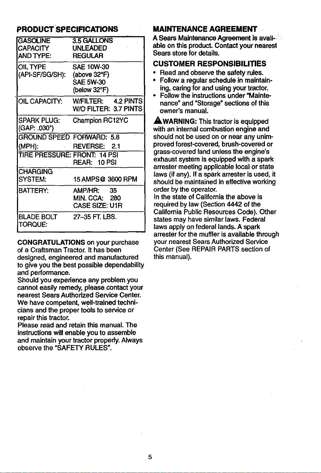
PRODUCT SPECIRCATIONS
GASOLINE 3.5 GALLONS
CAPACITY UNLEADED
AND TYPE: REGULAR
)ILTYPE SAE 10W-30
API-SF/SG/SH): (above 32°F)
SAE 5W-30
(below 32°F)
_ILCAPACITY: W/FILTER: 4.2 PINTS
W/O FILTER: 3.7 PINTS
SPARK PLUG: Champion RC12YC
GAP: .030")
GROUND SPEED FORWARD: 5.8
(MPH): REVERSE: 2.1
TIRE PRESSURE: FRONT: 14 PSI
REAR: 10 PSI
CHARGING
SYSTEM: 15 AMPS @ 3600 RPM
BATTERY: AMP/HR: 35
MIN, CCA: 280
CASE SIZE: U1R
BLADE BOLT 27-35 FT. LBS.
TORQUE:
CONGRATULATIONS on your purchase
of a Craftsman Tractor. It has been
designed, engineered and manufactured
to give you the best possible dependability
and performance.
Should you experience any problem you
cannot easily remedy, please contact your
nearest Sears Authorized Service Center.
We have competent, well-trained techni-
cians and the proper tools to service or
repair this tractor.
Please read and retain this manual. The
instructions will enable you to assemble
and maintain your tractor properly. Always
observe the =SAFETY RULES".
MAINTENANCE AGREEMENT
A Sears Maintenance Agreement isavail-
able on thisproduct.Contact your nearest
Sears storefor details.
CUSTOMER RESPONSIBILITIES
• Read and observe the safety rules.
• Follow a regular schedule in maintain-
ing, caring for and using your tractor.
• Follow the instructions under "Mainte-
nance" and =Storage" sections of this
owner's manual.
,_WARNING: This tractor is equipped
with an internal combustion engine and
should not be used on or near any unim-
proved forest-covered, brush-covered or
grass-covered land unless the engine's
exhaust system is equipped with a spark
arrester meeting applicable local or state
laws (if any). If a spark arrester is used, it
should be maintained in effective working
order by the operator.
In the state of Califomia the above is
required by law (Section 4442 of the
California Public Resources Code). Other
states may have similar laws. Federal
laws apply on federal lands. A spark
arrester for the muffler is available through
your nearest Sears Authorized Service
Center (See REPAIR PARTS section of
this manual).
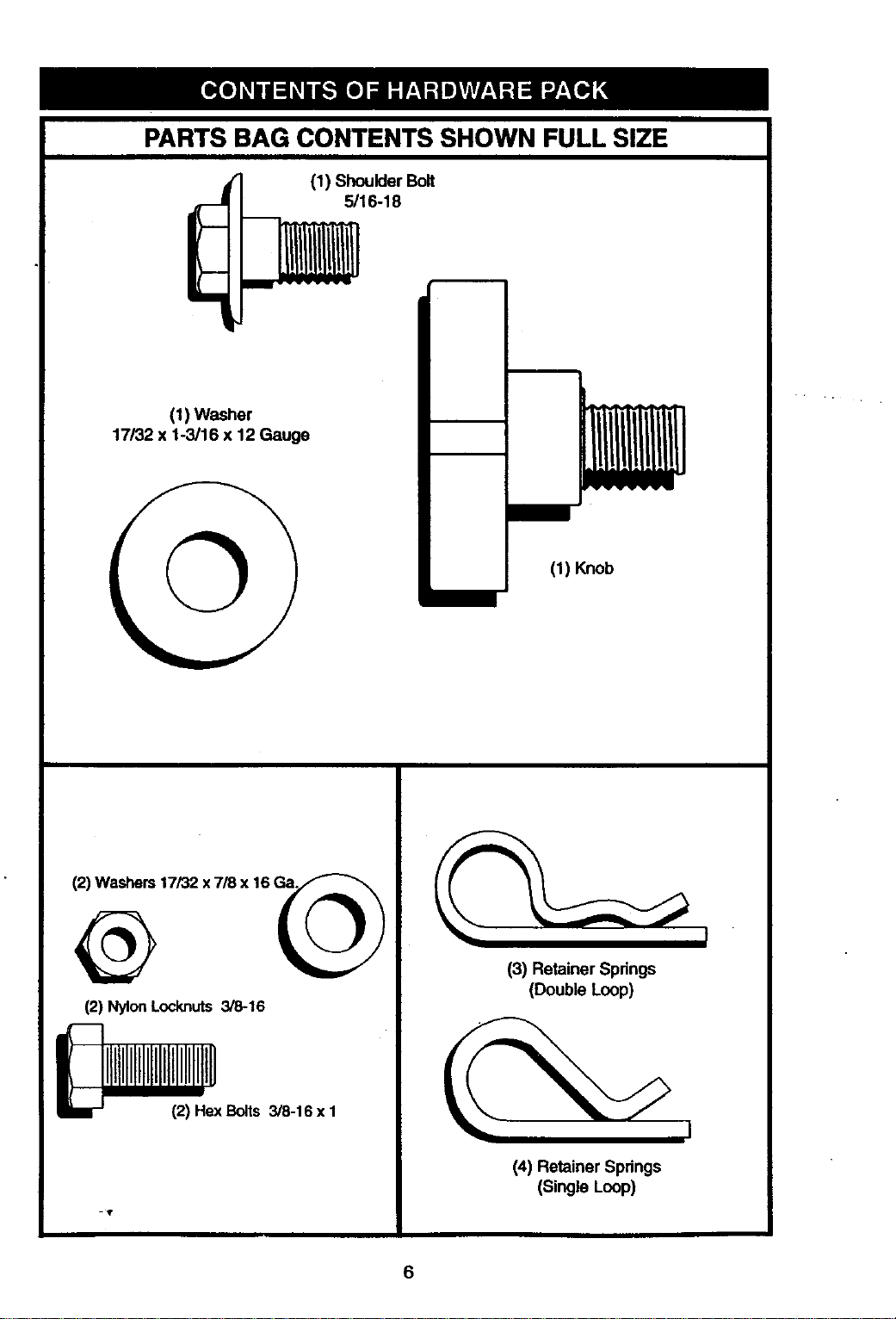
PARTS BAG CONTENTS SHOWN FULL SIZE
(1) Shoulder Bolt
5/16-18
(1) Washer
17/32 x 1-3/16 x 12 Gauge
(1) Knob
(2) Washers17/32 x 7/3 x 16 Ga.
(2) NylonLocknuts 3/8-16
i IIIIIIIIIIIIIH
12)HexBolts 3/8-16 x 1
(3) Retainer Springs
(Double Loop)
(4) Retainer Springs
(Single Loop)
6
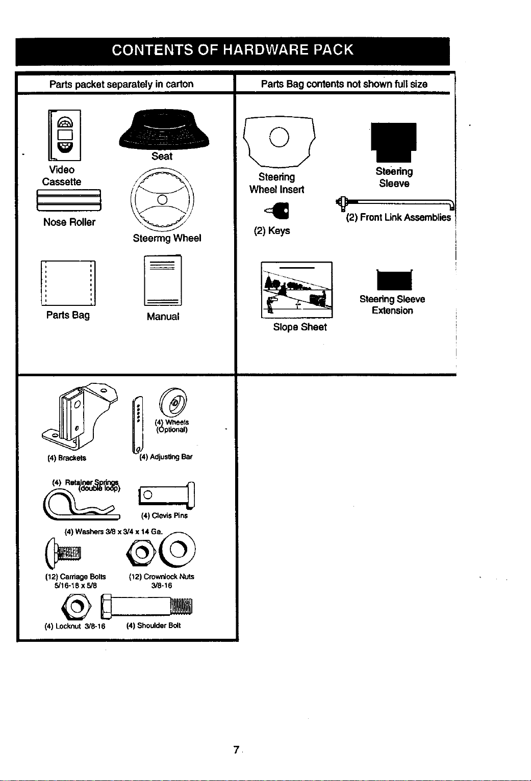
Pads packet separately in carton
Video
Cassette
L
L _
t J
Nose Roller
Seat
Steering Wheel
Parts Bag Manual
C
(4) Brackets _i!) Adjusting Bar
(12) CardageBolts {12) CrownJockNuts
5/16-18 x 3/8 3/8-16
@D w
(4) Lock.nut 3/8-16 (4) Shoulder Bo_t
Parts Bag contentsnot shown fullsize
©
Steering Steering
Sleeve
Wheel Insert
(2) Keys
(2) FrontLinkAssemblie,,
Slope Sheet
SteeringSleeve
Extension
,
Your new tractor has been assembled at the factory with exception of those parts left
unassembled for shipping purposes. To ensure safe and proper operation of your tractor
all parts and hardware y_u assemble must be tightened securely. Use the correct tools
as necessary to insure proper tightness. Review the video cassette before you begin.
TOOLS REQUIRED FOR
ASSEMBLY
-A socket wrench set will make assembly
easier. Standard wrench sizes you need
are listed below,
(I) 9/16" wrench (I) 314"Socket w/
(1)Pliers drive rachet
(1) 1/2" wrench (1) PhillipsScrew-
(1) Utilityknife driver
(1) Tire pressure gauge
When rightor left hand is mentioned in
this manual, it means, from your pointof
view, when you are in the operating posi-
tion (seated behind the steering wheel).
TO REMOVE TRACTOR FROM
CARTON
UNPACK CARTON
• Remove all accessible loose parts and
parts boxes from shipping carton (See
page 6).
• Cut, from top to bottom, along lines on
all four comers of shipping carton, and
lay panels flat.
• Check for any additional loose parts or
boxes and remove.
BEFORE ROLLING TRACTOR OFF
SKID
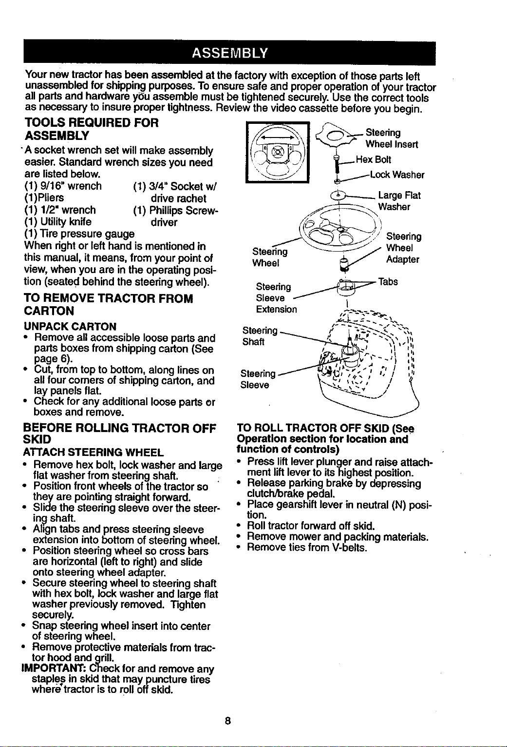
ATTACH STEERING WHEEL
• Remove hex bolt, lock washer and large
flat washer from steering shaft.
• Position front wheels of the tractor so
they are pointing straight forward.
• Slide the steering sleeve over the steer-
in._shaft.
• Ahgn tabs and press steering sleeve
extension into bottom of steering wheel.
• Position steering wheel so cross bars
are horizontal (left to right) and slide
onto steering wheel adapter.
• Secure steering wheel to steering shaft
with hex bolt, lock washer and large flat
washer previously removed. Tighten
securely.
• Snap steering wheel insert into center
of steering wheel.
• Remove protective materials from trac-
tor hood and grill.
IMPORTANT: Check for and remove any
staples in skid that may puncture tires
where tractor is to r011off skid.
I !l en0
Wheel Insert
_... Hex Bolt
_._-Lock Washer
@---..-__ Large Rat
Washer
Steering
Steering Wheel
Wheel Adapter
Steering _......._:::=- Tabs
Sleeve _ /
Extension ,;T.__-__..._.
_._1loll I I \ _/I I
"' '
Steering ] e, ! ,
_leeve __
TO ROLL TRACTOR OFF SKID (See
Operation section for location and
function of controls)
Press lift lever plunger and raise attach-
:ment lift lever to
itshighest
position.
Release parking brake by depressing
clutch/brake pedal.
• Place gearshift lever in neutral (N) posi-
tion.
• Roll tractor forward off skid.
Remove mower and packing materials.
•" Remove ties from V-belts.
8
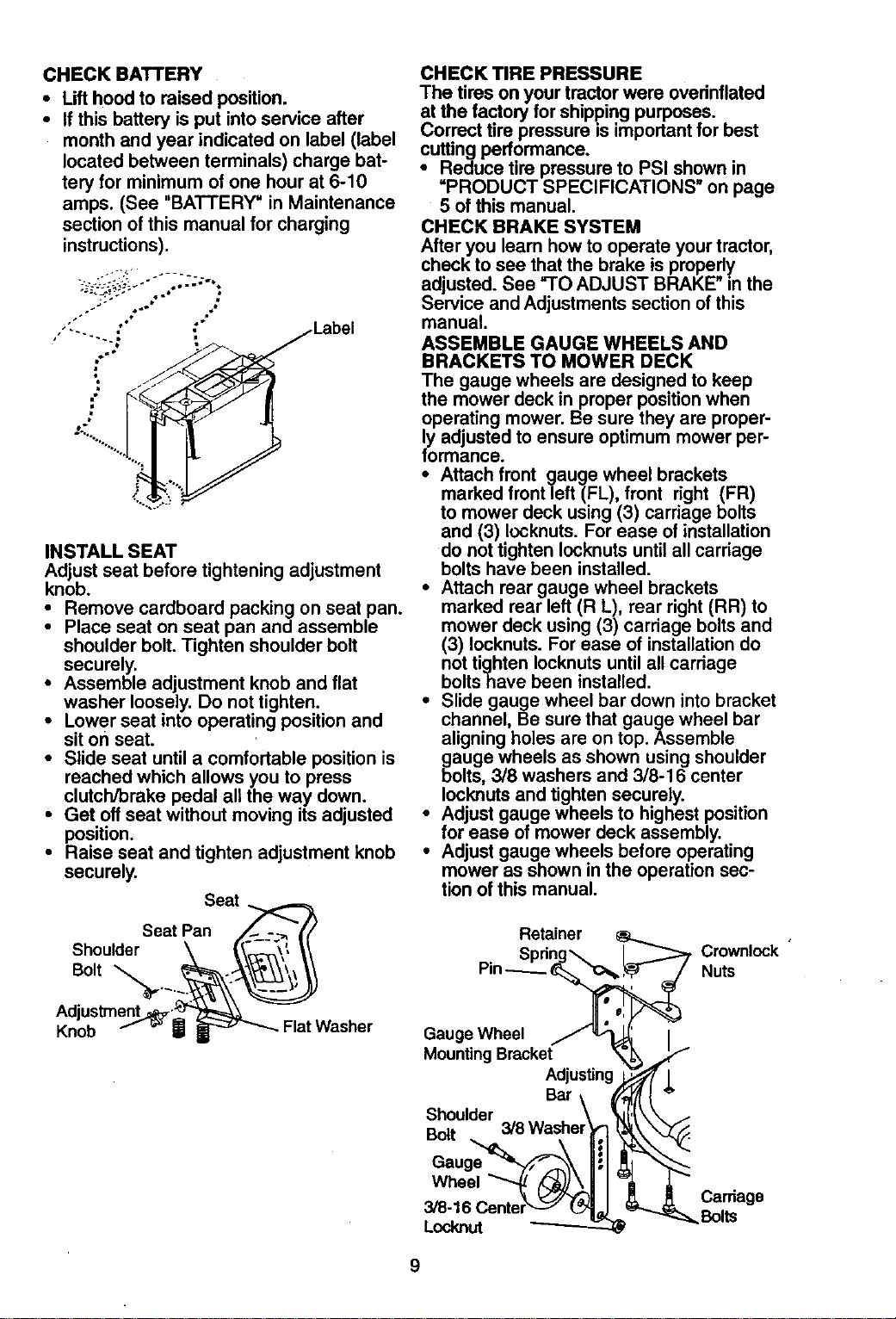
CHECKBATTERY
• Lift hood to raised position.
• If this battery is put into service after
month and year indicated on label (label
located between terminals) charge bat-
tery for minimum of one hour at 6-10
amps. (See "BATTERY" in Maintenance
section of this manual for charging
instructions).
,."-......_ _ /Label
INSTALL SEAT
Adjust seat before tightening adjustment
knob.
• Remove cardboard packing on seat pan.
• Place seat on seat pan and assemble
shoulder bolt. Tighten shoulder bolt
securely.
• Assemble adjustment knob and flat
washer loosely. Do not tighten.
• Lower seat into operating position and
sit on seat.
• Slide seat until a comfortable position is
reached which allows you to press
clutch/brake pedal all the way down.
• Get off seat without moving its adjusted
position.
• Raise seat and tighten adjustment knob
securely.
Seat
Seat Pan _
Shoulder \ tlt_.._'," \\
Bolt "_.___
AdjustmenL_ _
Knob f =" W _ Flat Washer
CHECKTIREPRESSURE
The tires on your tractor were ovednflatod
at the factory for shipping purposes.
Correct tire pressure is important for best
cutting performance.
• Reduce tire pressure to PSI shown in
=PRODUCT SPECIFICATIONS" on page
5 of this manual.
CHECK BRAKE SYSTEM
After you learn how to operate your tractor,
check to see that the brake is propedy
adjusted. See "TO ADJUST BRAKE"in the
Service and Adjustments section of this
manual.
ASSEMBLE GAUGE WHEELS AND
BRACKETS TO MOWER DECK
The gauge wheels are designed to keep
the mower deck in proper position when
operating mower. Be sure they are proper-
ly adjusted to ensure optimum mower per-
formance.
• Attach front gauge wheel brackets
marked front left (FL), front right (FR)
to mower deck using (3) carriage bolts
and (3) Iocknuts. For ease of installation
do not tighten Iocknuts until all carriage
bolts have been installed•
• Attach rear gauge wheel brackets
marked rear left (R L), rear right (RR) to
mower deck using (3) carriage bolts and
(3) Iocknuts. For ease of installation do
not tighten Iocknuts until all carriage
boltshave been installed.
• Slide gauge wheel bar down into bracket
channel, Be sure that gauge wheel bar
aligning holes are on top. Assemble
gbaugewheels as shown using shoulder
olts, 3/8 washers and 3/8-16 center
lock,nuts and tighten securely.
• Adjust gauge wheels to highest position
for ease of mower deck assembly.
• Adjust gauge wheels before operating
mower as shown in the operation sec-
tion of this manual.
Retainer
Crownlock
Nuts
Gauge Wheel
Moun_ng Bracket
Adjus_ng
Bar
Shoulder
BAt .
Gauge_,
Carriage
Bolts
9
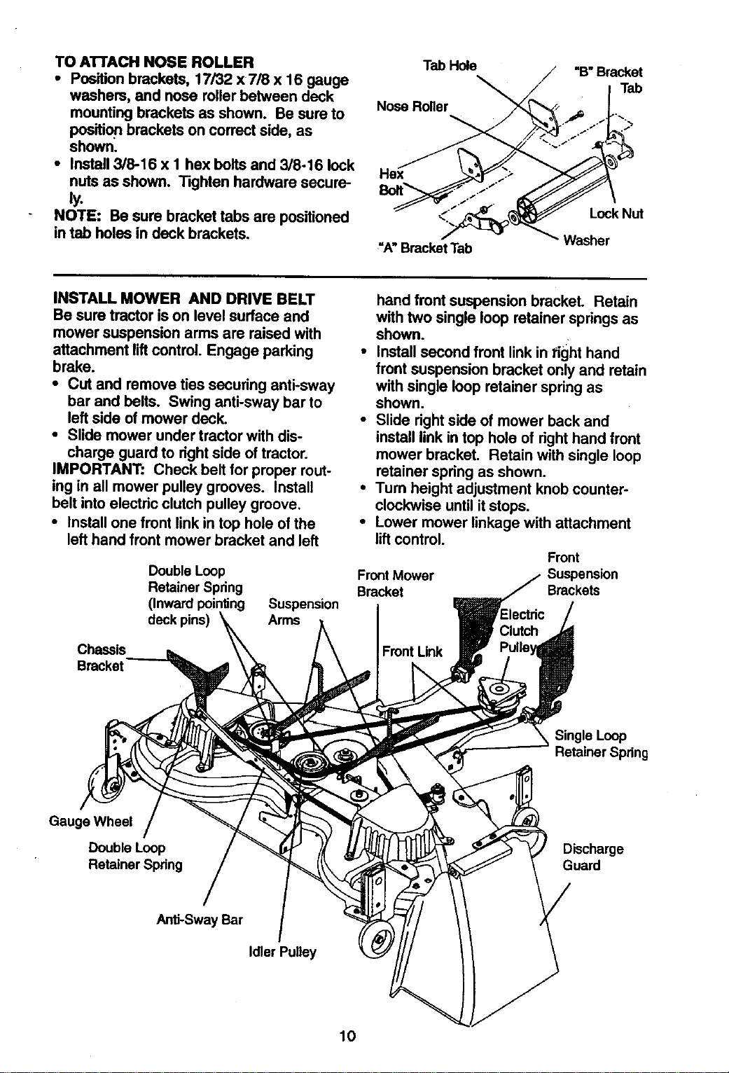
TOA'n'ACHNOSEROLLER
• Positionbrackets,17/32x7/8x 16gauge
washem,andnoserollerbetweendeck
mounting brackets as shown. Be sure to
position brackets on correct side, as
shown.
• Install 3/8-16 x 1 hex bolts and 3/8-16 lock
nuts as shown. Tighten hardware secure-
NOTE: Be sure bracket tabs are positioned
in tab holes in deck brackets.
Tab Hole "B"Bracket
Tab
Nose Roller
"A" BracketTab
Lock Nut
Washer
INSTALL MOWER AND DRIVE BELT
Be sure tractor ison level surface and
mower suspension arms are raised with
attachment liftcontrol. Engage parking
brake.
• Cut and remove ties securing anti*sway
bar and belts. Swing anti-sway bar to
left side of mower deck.
• Slide mower under tractor withdis-
charge guard to rightside of tractor.
IMPORTANT: Check belt for proper rout-
ing in all mower pulley grooves. Install
belt intoelectric clutch pulley groove.
• Installone front linkin top hole of the
left hand front mower bracket and left
Double Loop
Retainer Spring
(Inward pointing Suspension
deck pins) Arms
Chassis
Bracket
FrontMower
Bracket
hand front suspension bracket. Retain
with two single loop retainer springs as
shown.
• Install second front link in right hand
front suspension bracket only and retain
with single loop retainer spring as
shown.
• Slide right side of mower back and
install link in top hole of right hand front
mower bracket. Retain with single loop
retainer spring as shown.
• Tum height adjustment knob counter-
clockwise until it stops.
• Lower mower linkage with attachment
lift control.
Front
Suspension
Brackets
Front Link
Single Loop
Retainer Spring
Gauge Wheel
Double Loop
Retainer Spring
Discharge
Guard
Anti-Sway Bar
Idler Pulley
10
• Place the suspension arms on inward
pointing deck pins. If necessary, reck
and raise front of mower to align deck
pins with the holes in suspension arms.
Retain with double loop retainer springs
with loops down as shown.
• Connect anti-sway bar to chassis brack-
et under left footrest and retain with
double loop retainer spring.
• - Turn height adjustment knob clockwise
to remove slack from mower suspen-
sion.
• Raise deck to highest position.
• Adjust gauge wheels before operating
mower as shown in the Operation sec-
tion of this manual.
CHECK MOWER LEVELNESS
For best cutting results, mower should be
properly leveled. See "TO LEVEL
MOWER HOUSING" in the Service and
Adjustments section of this manual.
CHECK FOR PROPER POSITION OF
ALL BELTS
See the figures that are shown for replac-
ing motion, mower drive, and mower blade
drive belts in the Service and Adjustments
section of this manual. Verify that the
belts are routed correctly.
o/CHECKLIST
Please review the following checklist:
,/ All assembly instructions have been
completed.
,/No remaining loose parts in carton.
•/ Battery is properly prepared and
charged. (Minimum 1 hour at 6 amps).
•/ Seat is adjusted comfortably and tight-
ened securely.
•/ All tires are properly inflated. (For ship
ping purposes, the tires were ovednflat-
ed at the factory).
,/Be sure mower deck is propedy leveled
side-to-side/front-to-rear for best cutting
results. ('l]res must be properly inflated
for leveling).
,/Check mower and drive belts. Be sure
they are routed properly around pulleys
and inside all belt keepers.
•/ Check wiring. See that all connections
are still secure and wires are properly
clamped.
•/ Before driving tractor, be sure freewheel
control is in drive position.
While learning how to use your tractor,
pay extra attention to the following impor-
tant items:
,/Engine oil is at proper level.
,/Fuel tank is filled with fresh, clean, regu-
lar unleaded gasoline.
•/ Become familiar with all controls - their
location and function. Operate them
before you start the engine.
,/Be sure brake system is in safe operat-
ing condition.
•/ It is important to purge the transmission
before operating your tractor for the first
time. Follow proper starting and trans-
mission purging instructions (See "TO
START ENGINE" and "PURGE TRANS-
MISSION" in the Operation section of
this manual).
11
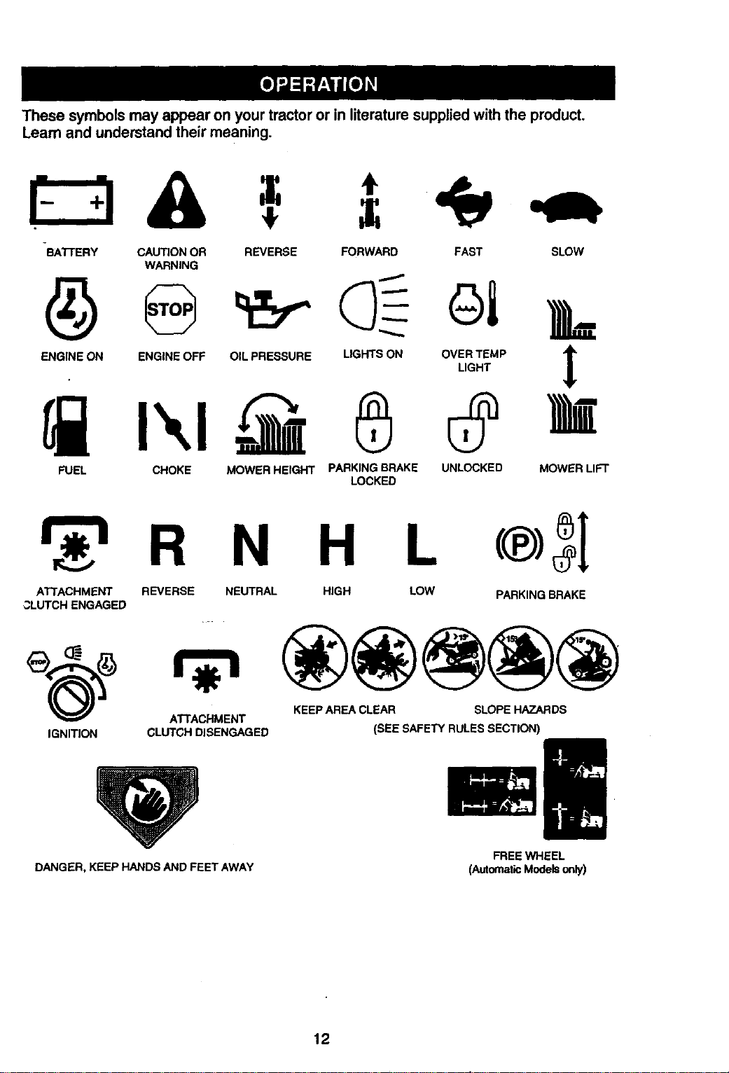
These symbols may appear on your tractor or in literature suppliedwith the product.
Learn and understand their meaning.
BATI'ERY CAUTION OR
WARNING
ENGINE ON ENGINE OFF
REVERSE FORWARD FAST SLOW
OIL PRESSURE
FUEL CHOKE MOWER HEIGHT
PARKING BRAKE UNLOCKED MOWER LIFT
LOCKED
R N H L
ATTACHMENT REVERSE NEUTRAL HIGH LOW PARKING BRAKE
3LUTCH ENGAGED
KEEP AREA CLEAR SLOPE HAZARDS
ATI"ACHMENT
IGNITION CLUTCH DISENGAGED (SEE SAFETY RULES SECTION)
DANGER, KEEP HANDS AND FEET AWAY
FREE WHEEL
(Automatic Models only)
12
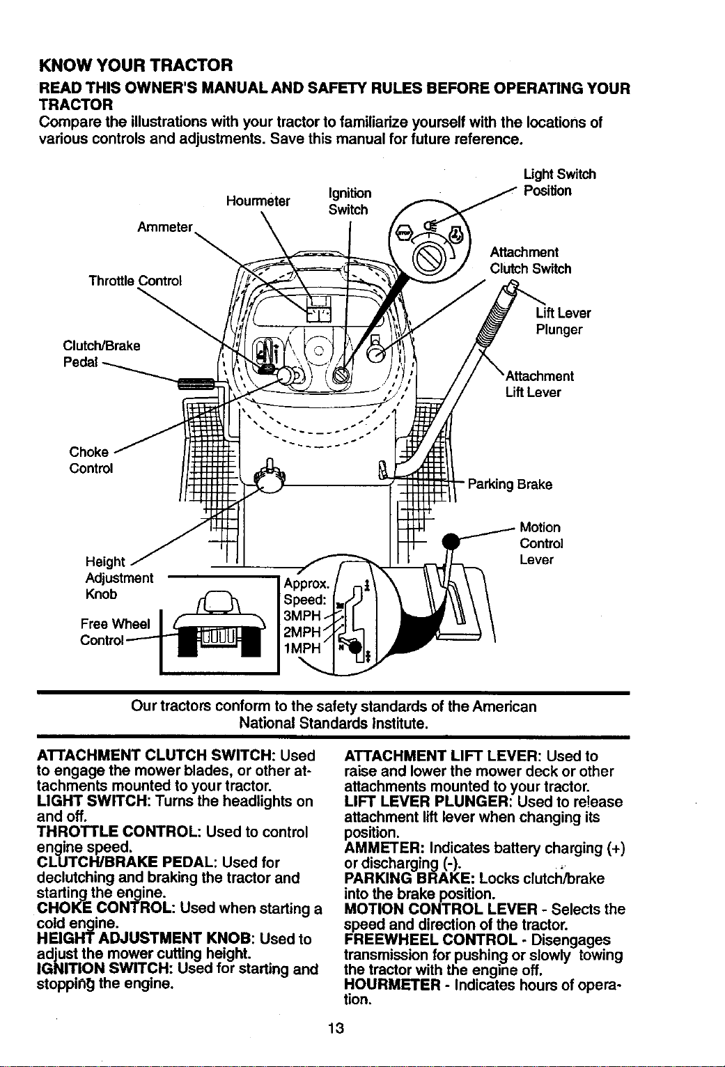
KNOW YOUR TRACTOR
READ THIS OWNER'S MANUAL AND SAFETY RULES BEFORE OPERATING YOUR
TRACTOR
Compare the illustrationswith your tractorto familiarize yourself with the locations of
various controls and adjustments. Save this manualfor future reference.
Hourmeter Ignition
Switch
Ught Switch
Position
Ammeter
Attachment
Clutch Switch
Throttle Control
Clutch/Brake
Lift Lever
Plunger
Lift Lever
Choke
Control
- Parking Brake
Height
Adjustment
Knob
Free Wheel
Motion
Control
Lever
Our tractors conform to the safety standards ofthe American
National Standards Institute.
ATTACHMENT CLUTCH SWITCH: Used
to engage the mower blades, or other at-
tachments mounted to your tractor.
LIGHT SWITCH: Turns the headlights on
and off.
THROTTLE CONTROL: Used to control
engine speed.
CLUTCH/BRAKE PEDAL: Used for
declutching and braking the tractor and
starling the engine.
CHOKE CONTROL: Used when starting a
cold engine.
HEIGHT ADJUSTMENT KNOB: Used to
adjust the mower cutting height.
IGNITION SWITCH: Used for starting and
stoppin_] the engine.
ATTACHMENT LIFT LEVER: Used to
raise and lower the mower deck or other
attachments mounted to your tractor.
LIFT LEVER PLUNGER: Used to re!ease
attachment lift lever when changing its
position.
AMMETER: Indicates battery charging (+)
or discharging (-).
PARKING BRAKE: Locks clutci_brake
into the brake position.
MOTION CONTROL LEVER - Selects the
speed and direction of the tractor.
FREEWHEEL CONTROL - Disengages
transmission for pushing or slowly towing
the tractor with the engine off.
HOURMETER - Indicates hours of opera-
tion.
13
The operation of any tractor can result inforeign objects thrown intothe
eyes, which can resultin severe eye damage. Always wear safety glasses
or eye shields while operating your tractor or performing any adjustments or
repairs. We recommend a wide vision safety mask over spectacles, or stan-
dard safety glasses.
HOW TO USE YOUR TRACTOR
Your tractor is equipped with an operator
presence sensing switch.When engine is
running, any attempt by the operator to
leave the seat without firstsetting the
parking brake will shutoff the engine.
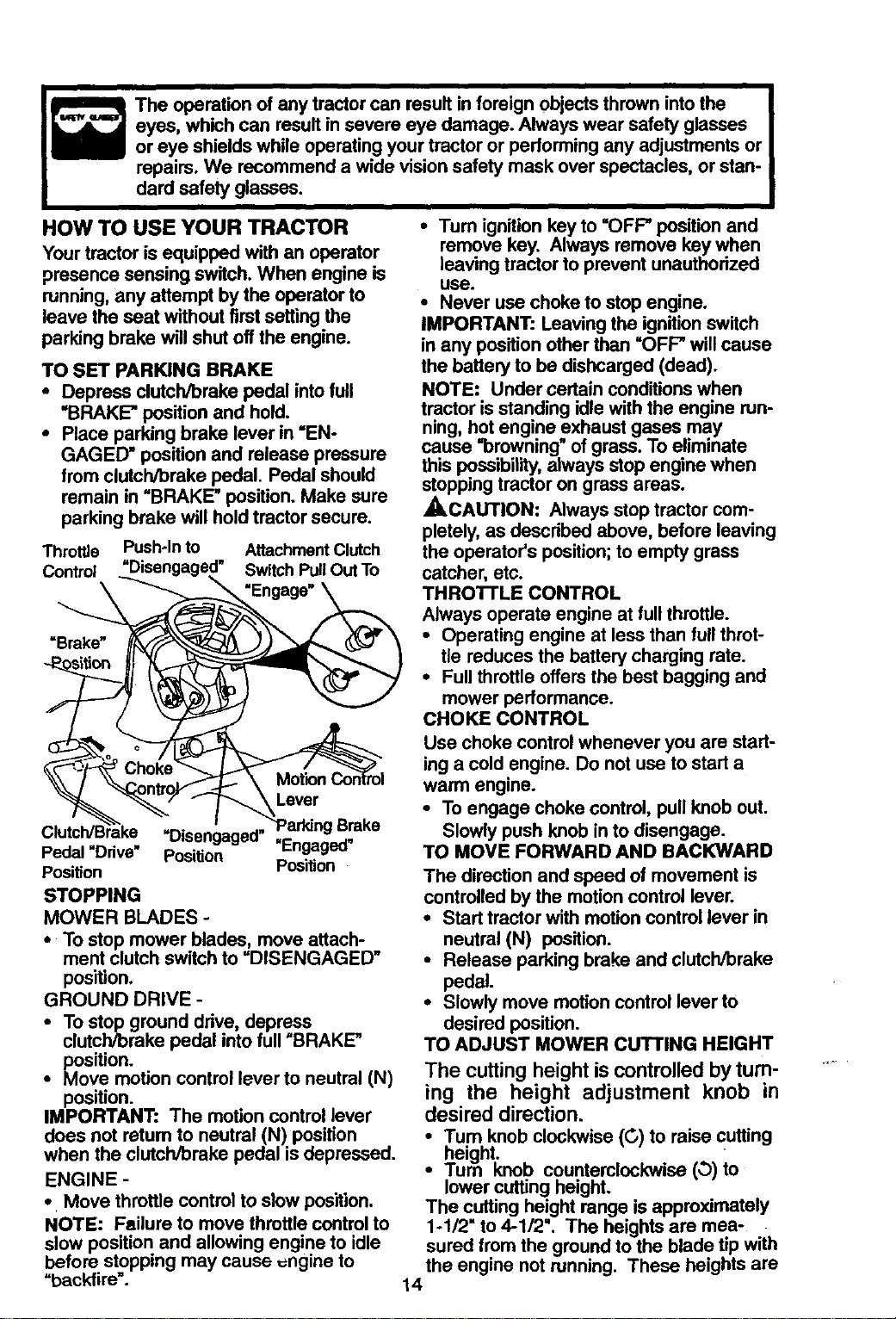
TO SET PARKING BRAKE
• Depress clutch/brake pedal intofull
"BRAKE"position and hold.
• Place parking brake lever in =EN-
GAGED" positionand release pressure
fromclutch/brake pedal, Pedal should
remain in =BRAKE"position. Make sure
parking brake will holdtractor secure.
Throttle Push*In to Attachment Clutch
Control ._'Disengaged" Switch PullOutTo
\_"_ "Engage" \
Pedal Ddve Position Y _
Position Position
STOPPING
MOWER BLADES -
• To stop mower blades, move attach-
ment clutch switch to =DISENGAGED"
position.
GROUND DRIVE -
• To stop ground drive, depress
clutch/brake pedal into full =BRAKE"
position.
• Move motion control lever to neutral (N)
position.
IMPORTANT: The motion control lever
does not retum to neutral (N) position
when the clutch/brake pedal is depressed.
ENGINE -
• Move throttle control to slow pos'_mn.
NOTE: Failure to move throttle control to
slow position and allowing engine to idle
before stopping may cause =ngine to
=backfire'.
• Turn ignition key to =OFF" position and
remove key. Always remove key when
leaving tractor to prevent unauthorized
USa.
• Never use choke to stop engine.
IMPORTANT: Leaving the ignition switch
in any position other than =OFF" will cause
the battery to be dishcarged (dead).
NOTE: Under certain conditions when
tractor is standing idle with the engine run-
ning, hot engine exhaust gases may
cause =browning" of grass. To eliminate
this possibility, always stop engine when
stopping tractor on grass areas.
_CAUTION: Always stop tractor com-
pletely, as described above, before leaving
the operator's position; to empty grass
catcher, etc.
THROTrLE CONTROL
Always operate engine at full throttle.
• Operating engine at less than full thret-
tie reduces the battery charging rate.
• Full throttle offers the best bagging and
mower performance.
CHOKE CONTROL
Use choke control whenever you are start-
ing a cold engine. Do not use to start a
warm engine.
• To engage choke control, pull knob out.
Slowly push knob in to disengage.
TO MOVE FORWARD AND BACKWARD
The direction and speed of movement is
controlled by the motion control lever.
• Start tractor with motion control lever in
neutral (N) position.
• Release parking brake and clutch/brake
pedal.
° Slowly move motion control lever to
desired position.
TO ADJUST MOWER cur'rING HEIGHT
The cutting height is controlled by tum-
ing the height adjustment knob in
desired direction.
• Tum knob clockwise(C,)to raise cutting
height.
• /um knob counterclockwise (O)to
lower cutting height.
The cutting height range is approximately
1-1/2" to 4-1/2". The heightsare mea-
sured fromthe groundto the blade tip with
the engine not running. These heights are
14
approximate and may vary depending
upon soil conditions, height of grass and
types of grass being mowed.
• The average lawn should be cut to
approximately 2-1/2 inches during the
cool season and to over 3 inches during
hot months. For healthier and better
looking lawns, mow often and after
moderate growth.
• . For best cutting performance, grass
over 6 inches in hek3ht should be
mowed twice. Make the first cut rela-
tively high; the second to desired height.
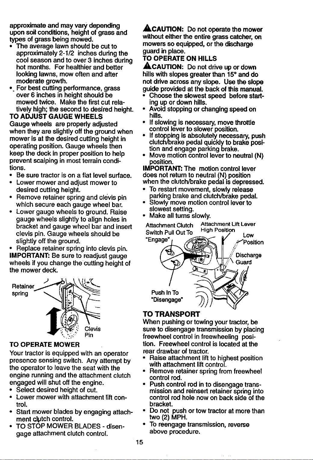
TO ADJUST GAUGE WHEELS
Gauge wheels are properly adjusted
when they are slightly off the ground when
mower is at the desired cutting height in
operating position. Gauge wheels then
keep the deck in proper position to help
prevent scalping in most terrain condi-
tions.
• Be sure tractor is on a flat level surface.
• Lower mower and adjust mower to
desired cutting height.
• Remove retainer spring and clevis pin
which secure each gauge wheel bar.
• Lower gauge wheels to ground. Raise
gauge wheels slightly to align holes in
bracket and gauge wheel bar and insert
clevis pin. Gauge wheels should be
slightly off the ground.
• Replace retainer spring into clevis pin.
IMPORTANT: Be sure to readjust gauge
wheels if you change the Cutting height of
the mower deck.
Retainer
spring
Clevis
,._.: Pin
TO OPERATE MOWER
Your tractor is equipped with an operator
presence sensing switch. Any attempt by
the operator to leave the seat with the
engine running and the attachment clutch
engaged will shut off the engine.
• Select desired height of cut.
• Lower mower with attachment lift con-
trol.
• Start mower blades by engaging attach-
ment clptch control.
• TO STOP MOWER BLADES - disen-
gage attachment clutch control.
_,CAUTION: Do not operate the mower
without either the entire grass catcher, on
mowers so equipped, or the discharge
guard in place.
TO OPERATE ON HILLS
_,CAUTION: Do not drive up or down
hills with slopes greater than 15° and do
not drive across any slope. Use the slope
guide provided at the back of this manual.
• Choose the slowest speed before start-
ing up or down hills.
• Avoid stopping or changing speed on
hills.
• If slowing is necessary, move throttle
control lever to slower position.
i f stopping is absolutely necessary, push
clutch/brake pedal qulcklyto brake posi-
tion and engage parking brake.
Move motion control lever to neutral (N)
position.
IMPORTANT: The motion control lever
does not return to neutral (N) position
when the clutch/brake pedal is depressed.
• To restart movement, slowly release
parking brake and clutch/brake pedal.
• Slowly move motion control lever to
slowest setting.
• Make all tums slowly.
Attachment Clutch Attachment L_ Lever
Switch Pull OutTo High Position
"Engage" _ / LOW
,j-_'Position
Push InTo _, _-._
"Oisengo0 "
TO TRANSPORT
When pushing or towing your tractor, be
sure to disengage transmission by placing
freewheel control in freewheeling posi-
tion. Freewheel control is located at the
rear drawbar of tractor.
• Raise attachment lift to highest position
with attachment lift control,
• Remove retainer spring from freewheel
control rod.
• Push control rod in to disengage.trans-
mission and reinsert retainer spnng into
control rod hole now on back side of the
bracket.
• Do not push or tow tractor at more than
two (2) MPH.
• To reengage transmission, reverse
above procedure.
15
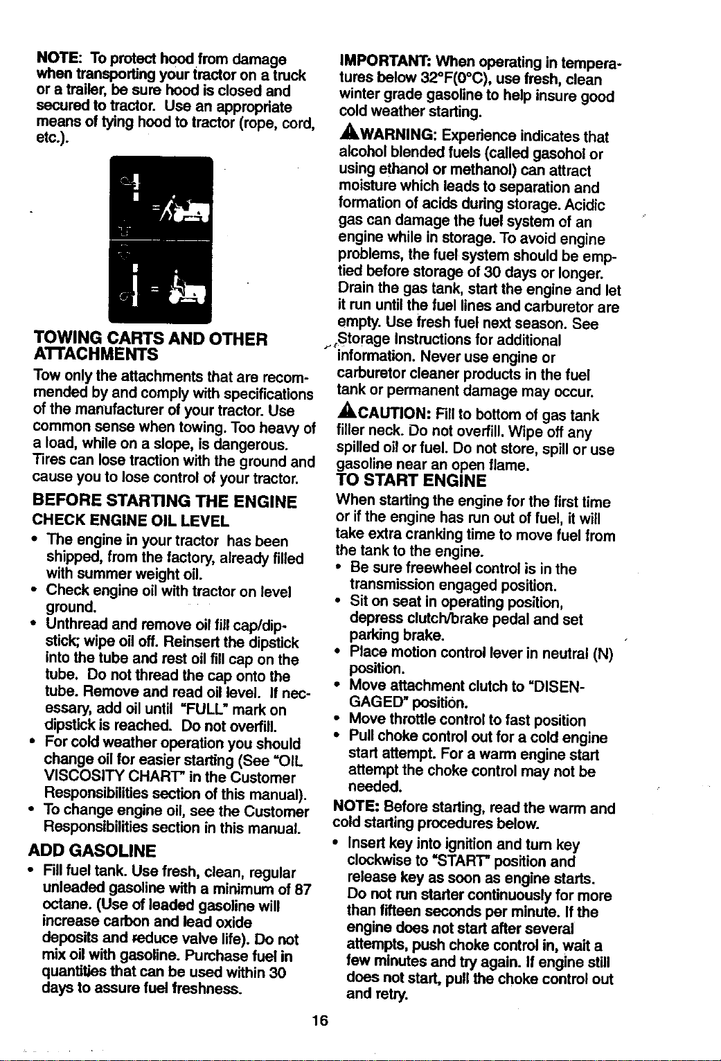
NOTE: Toprotect hood fromdamage
when transportingyour tractor on a truck
or a trailer, be sure hood isclosed and
secured to tractor. Use an appropriate
means of tying hoodto tractor (rope, cord,
etc.).
TOWING CARTS AND OTHER
A'n'ACHMENTS
Tow on!ythe attachments that are recom-
mended by and complywith specifications
of the manufacturer of your tractor. Use
common sense when towing. Too heavy of
a load, while on a slope, is dangerous.
Tires can lose tractionwith the ground and
cause you to lose controlof your tractor.
BEFORE STARTING THE ENGINE
CHECK ENGINE OIL LEVEL
• The engine in your tractor has been
shipped, from the factory, already filled
with summer weight oil.
• Check engine oil with tractor on level
ground.
• Unthread and remove oil fill cap/dip
stick; wipe oil off. Reinsert the dipstick
into the tube and rest oil fill cap on the
tube. Do not thread the cap onto the
tube. Remove and read oil level. If nec-
essary, add oil until "FULL" mark on
dipstick is reached. Do not overfill.
• For cold weather operation you should
change oil for easier starting (See =OIL
VISCOSITY CHARC' in the Customer
Responsibilities section of this manual).
• To change engine oil, see the Customer
Responsibilities section in this manual.
ADD GASOLINE
• Fill fuel tank. Use fresh, clean, regular
unleaded gasoline with a minimum of 87
octane. (Use of leaded gasoline will
increase carbon and lead oxide
deposits and reduce valve life). Do not
mix oil with gasoline. Purchase fuel in
quantities that can be used within 30
days to assure fuel treshness.
16
IMPORTANT: When operating in tempera-
tures below 32°F(0°C), use fresh, clean
winter grade gasoline to help insure good
cold weather starting.
_,WARNING: Expedance indicates that
alcohol blended fuels (called gasohol or
using ethanol or methanol) can attract
moisture which leads to separation and
formation of acids during storage. Acidic
gas can damage the fuel system of an
engine while in storage. To avoid engine
problems, the fuel system should be emp-
tied before storage of 30 days or longer.
Drain the gas tank, start the engine and let
it run until the fuel lines and carburetor are
empty. Use fresh fuel next season. See
,._Storage Instructions for additional
information. Never use engine or
carburetor cleaner products in the fuel
tank or permanent damage may occur.
_,CAUTION: Fill to bottom of gas tank
filler neck. Do not overfill. Wipe off any
spilled oil or fuel. Do not store, spill or use
gasoline near an open flame.
TO START ENGINE
When startingthe engine for the firsttime
or if the engine has run out of fuel, itwill
take extra cranking time to movefuel from
the tank to the engine.
• Be sure freewheel control is in the
transmissionengaged position.
• Sit on seat in operating position,
depress clutch/brake pedal and set
parking brake.
• Race motion controllever in neutral (N)
position.
• Move attachment clutchto "DISEN-
GAGED _posit'_n.
• Move throttlecontrolto fast position
• Pull choke control outfor a cold engine
start attempt. For a warm engine start
attempt the choke control may not be
needed.
NOTE: Before starting,read the warm and
cold startingprocedures below.
• Insert key intoignitionand tum key
clockwiseto "START" positionand
release key as soon as engine starts.
Do not runstarter continuouslyfor more
thanfifteen seconds per minute. Ifthe
engine does notstart after several
attempts, push choke control in, wait a
few minutes and try again. If engine still
does not start, pull the choke control out
and retry.
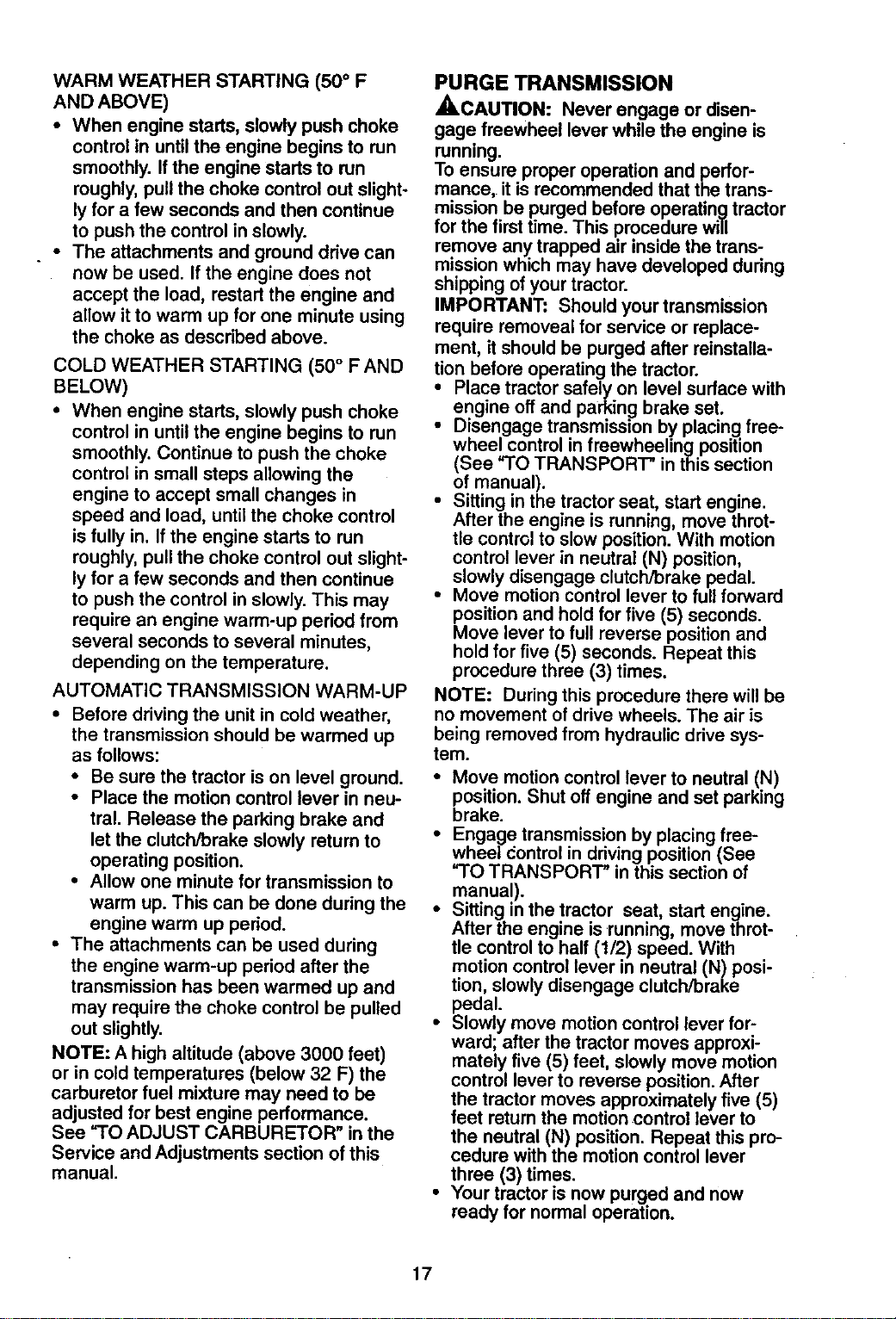
WARM WEATHER STARTING (50 ° F
AND ABOVE)
• When engine starts, slowly push choke
control in until the engine begins to run
smoothly. If the engine starts to run
roughly, pull the choke control out slight-
ly for a few seconds and then continue
to push the control in slowly.
• The attachments and ground drive can
now be used. If the engine does not
accept the load, restart the engine and
allow itto warm up for one minute using
the choke as described above.
COLD WEATHER STARTING (50 ° F AND
BELOW)
• When engine starts, slowly push choke
control in until the engine begins to run
smoothly. Continue to push the choke
control in small steps allowing the
engine to accept small changes in
speed and load, until the choke control
is fully in. If the engine starts to run
roughly, pull the choke control out slight-
ly for a few seconds and then continue
to push the control in slowly. This may
require an engine warm-up period from
several seconds to several minutes,
depending on the temperature.
AUTOMATIC TRANSMISSION WARM-UP
• Before driving the unit in cold weather,
the transmission should be warmed up
as follows:
• Be sure the tractor is on level ground.
• Place the motion control lever in neu-
tral. Release the parking brake and
let the clutch/brake slowly return to
operating position.
• Allow one minute for transmission to
warm up. This can be done during the
engine warm up period.
• The attachments can be used during
the engine warm-up period after the
transmission has been warmed up and
may require the choke control be pulled
out slightly.
NOTE: A high altitude (above 3000 feet)
or in cold temperatures (below 32 F) the
carburetor fuel mixture may need to be
adjusted for best engine performance.
See "TO ADJUST CARBURETOR" in the
Service and Adjustments section of this
manual.
PURGE TRANSMISSION
_,CAUTION: Never engage or disen-
gage freewheel lever while the engine is
running.
To ensure proper operation and perfor-
mance, it is recommended that the trans-
mission be purged before operating tractor
for the first time. This procedure will
remove any trapped air inside the trans-
mission which may have developed during
shipping of your tractor.
IMPORTANT: Should your transmission
require removeal for service or replace-
ment, it should be purged after reinstalla-
tion before operating the tractor.
• Place tractor safely on level surface with
engine off and parking] brake set.
• Disengage transmisszon by placing free-
wheel control in freewheeling position
(See "TO TRANSPORT" in this section
of manual).
• Sitting in the tractor seat, start engine.
After the engine is running, move throt-
tle control to slow position. With motion
control lever in neutral (N) position,
slowly disengage clutch/brake pedal.
• Move motion control lever to full forward
position and hold for five (5) seconds.
Move lever to full reverse position and
hold for five (5) seconds. Repeat this
procedure three (3) times.
NOTE: During this procedure there will be
no movement of drive wheels. The air is
being removed from hydraulic drive sys-
tem.
• Move motion control lever to neutral (N)
position. Shut off engine and set parking
brake.
• Engage transmission by placing free-
wheel _ontrol in driving position (See
"TO TRANSPORT" in this section of
manual).
• Sitting in the tractor seat, start engine.
After the engine is running, move throt-
tle control to half (1/2) speed. With
motion control lever in neutral (N) posi-
tion, slowly disengage clutch/brake
pedal.
• Slowly move motion control lever for-
ward; after the tractor moves approxi-
mately five (5) feet, slowly move motion
control lever to reverse position. After
the tractor moves approximately five (5)
feet return the motion control lever to
the neutral (N) position. Repeat this pro-
cedure with the motion control lever
three (3) times.
• Your tractor is now purged and now
ready for normal operation.
17
MOWINGTIPS
• Tire chains cannot be used when the
mower housing is attached to tractor.
• Mower should be propedy leveled for
best mowing performance. See "TO
LEVEL MOWER HOUSING" in the
Service and Adjustments section of this
manual.
• Use the runner on the dght hand side of
. mower as a guide. The blade cuts
approximately an inch outside the run-
ner.
• The left hand side of mower should be
used for trimming.
• Drive so that clippings are discharged
onto the area that has been cut. Have
the cut area to the dght of the tractor.
This will result in a more even distribu-
tion of clippings and more uniform cut-
ting.
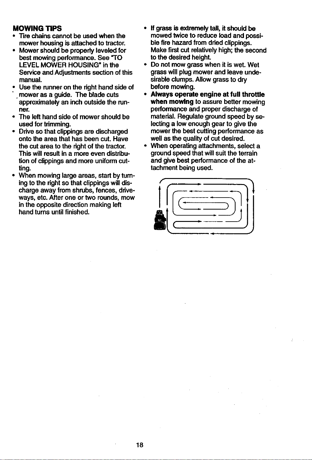
• When mowing large areas, start by tum-
ing to the right so that clippings will dis-
charge away from shrubs, fences, ddve-
ways, etc. After one or two rounds, mow
in the opposite direction making left
hand turns until finished.
• If grass is extremely tall, itshould be
mowed twice to reduce load and possi-
ble fire hazard from dried clippings.
Make first cut relatively high;the second
to the desired height.
• Do not mow grass when itis wet. Wet
grass willplug mower and leave unde-
sirableclumps. Allow grass to dry
before mowing.
• Always operate engine at full throttle
when mowing to assure better mowing
performance and proper discharge of
material. Regulate ground speed by se-
lectinga low enough gear to give the
mower the best cutting performance as
well as the qualityof cut desired.
• When operating attachments, select a
groundspeed that willsuit the terrain
and give best performance of the at-
tachment being used.
18
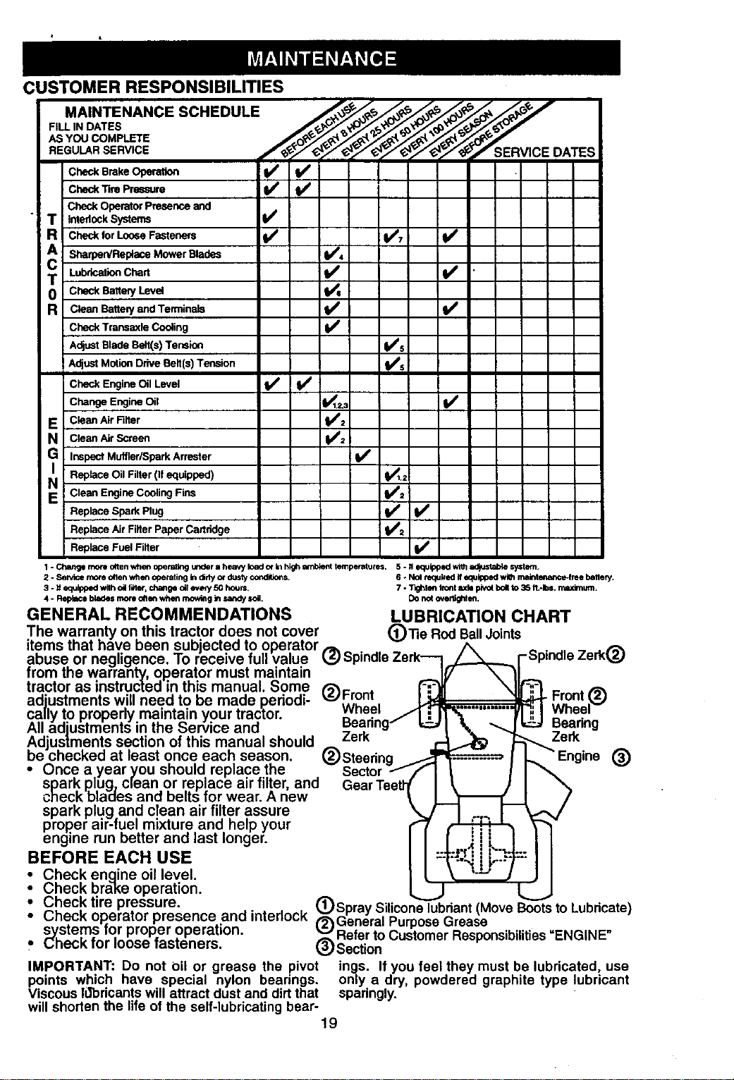
CUSTOMER RESPONSIBILITIES
mml_
C c.BrakeO I/ V'
V' I/
Operator Presence and
T ,ntedock Systems _4
Check for Loose Fasteners 11117 I1e
CA SharperdReptace M°wer Blades i_ 4
LubricationChart V'
R clean Battee/and Terminals II_
Check Transaxle Cooling V'
AdjustBlade Be_t(s)Tension _'s
AdjustMotionDrive Belt(s) Tension _5
Check Engine Oil Level if ! I_
Change Engine Oil _1.=,_ IP1'
E CleanAirniter _:
N Clean Air Screen
v'
Inspect Muffler/Spark Arrester
Replace Oil Filter(If equipped) ql_,2
N Clean Engine Cooling Fins _:
Replace Spark Plug V'
Replace Air Filter Paper CaJtridge
Replace Fuel Filter If
1 - Change more often when operating under a heavy load or kt high amblent temperatures. 5 - N equipped with ad/u_ab_ system.
2 - Servicemore oSenwh_ operatingIndidyordustycor_ditk_$, 6 - Nol wked If equippedwiChmaintm baltee/ .
3 - # equippedw#hoil filter,changeell every 50 hours. 7 - Tlght_ kent rodepivotbollto 35 ft.-Ib=,n_udmum.
4 * Fleplaceblades moti oft_ whenmow_g _ r,andyt,oi. Donotovertighlen.
GENERAL RECOMMENDATIONS LUBRICATION CHART
The warranty on this tractor does not cover (_)13e Rod BallJoints
items that have Deen subjected to operator
abuse or negdgence. Io receive full value 1,5 • -
from the warran_ operator must maintain
tractor as instructeo in this manual. Some ,'__ .
_J I-renT
adiustments will need to be made periodi- . . .
cally to properly maintain your tractor, wnaei
uea_
All adiustments in the Service and _ .
Adjustments section of this manual should /erK
De cnecKea at least once eacn season.
Engine (_)
• Once a year you should replace the
spark plug_ clean or replace air filter, and
check blaoes and belts for wear. A new
spark plug and clean air filter assure
proper air-fuel mixture and help your
engine run Detter and last longer.
BEFORE EACH USE
)Bp'nd'e Zer O
) Front r._. _ Front .(_
Wheel ._1_.__ I Wheel
Beadng / _1 tt_ _[_ Bearing
Zerk _ _... Zerk
®Steedng I-,."En
SGeeCtr°rff I I, I I
: Check engine oil level.
Check brake operation.
-.Check tire pressure. (_)Spray Silicone lubdant (Move Boots to Lubdcate)
Check op.erator presence and interlock ('_2_GeneralPurpose Grease
systems mr proper operation. _ Refer to Customer Responsibilities "ENGINE
Check for loose rasteners. _r_)Section
IMPORTANT: Do not oil or grease the pivot ings. If you feel they must be lubricated, use
points which have special nylon bearings, only a dry, powdered graphite type lubricant
Viscous ldbricants will attract dust and dirtthat sparingly.
will shorten the life of the self-lubricating bear-
19
TRACTOR
Alwaysobservesafetyruleswhenper-
forminganymaintenance.
BRAKEOPERATION
Iftractorrequiresmorethansix(6)feet
stoppingdistanceathighspeedinhighest
gear,thenbrakemustbeadjusted.(See
"TO ADJUST BRAKE" in the Service and
Adjustments section of this manual).
TIRES
• Maintain proper air pressure in all tires
(See =PRODUCT SPECIFICATIONS"
on page 5 of this manual).
• Keep tires free of gasoline, oil, or insect
control chemicals which can harm rub-
ber.
• Avoid stumps, stones, deep ruts, sharp
objects and other hazards that may
cause tire damage.
NOTE: To seal tire punctures and prevent
flat tires due to slow leaks, tire sealant
may be purchased from your local parts
dealer. Tire sealant also prevents tire dry
rot and corrosion.
OPERATOR PRESENCE SYSTEM
Be sure operator presence and interlock
systems are working properly. If your trac-
tor does not function as described below,
repair the problem immediately.
• The engine should not start unless the
clutch/brake pedal is fully depressed
and attachment clutch control is in the
disengaged position.
• When the engine is running, any
attempt by the operator to leave the
seat without first setting the parking
brake should shut off the engine.
• When the engine is running and the
attachment clutch is engaged, any
attempt by the operator to leave the
seat should shut off the engine.
• The attachment clutch should never
operate unless the operator is in the
seat.
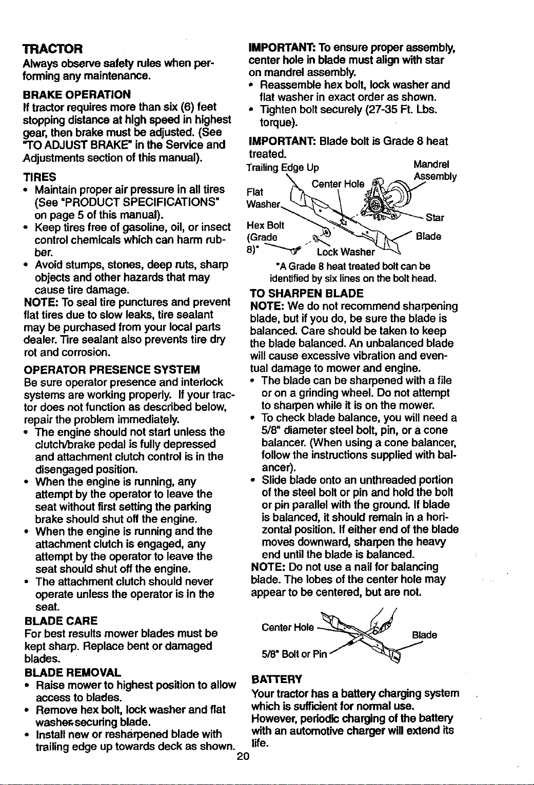
IMPORTANT: To ensure proper assembly,
center hole in blade must align with star
on mandrel assembly.
• Reassemble hex bolt, lock washer and
flat washer in exact order as shown.
• Tighten bolt securely (27-35 Ft. Lbs.
torque).
IMPORTANT: Blade bolt is Grade 8 heat
treated.
TrailingEdge Up Mandrel
Center Hole Assembly
Flat
Star
Hex Bolt
(Grade ._.,_ Blade
*A Grade 8 heat treated boltcan be
identifiedby sixlines on the bolthead.
TO SHARPEN BLADE
NOTE: We do not recommend sharpening
blade, but if you do, be sure the blade is
balanced. Care should be taken to keep
the blade balanced. An unbalanced blade
will cause excessive vibration and even-
tual damage to mower and engine.
° The blade can be sharpened with a file
or on a grinding wheel. Do not attempt
to sharpen while it is on the mower.
° To check blade balance, you will need a
5/8" diameter steel bolt, pin, or a cone
balancer. (When using a cone balancer,
follow the instructions supplied with bal-
ancer).
° Slide blade onto an unthreaded portion
of the steel bolt or pin and hold the bolt
or pin parallel with the ground. If blade
is balanced, it should remain in a hori-
zontal position. If either end of the blade
moves downward, sharpen the heavy
end until the blade is balanced.
NOTE: Do not use a nail for balancing
blade. The lobes of the center hole may
appear to be centered, but are not.
BLADE CARE
For best results mower blades must be
kept sharp. Replace bent or damaged
blades.
BLADE REMOVAL
• Raise mower to highest position to allow
access to blades.
• Remove hex bolt, lock washer and fiat
washer, securing blade.
• Install new or resharpened blade with
Blade
5/8" Boltor Pin
BATTERY
Your tractorhas a battery charging system
which issufficientfor normal use.
However, periodic charging of the battery
with an automotivecharger willextend its
trailingedge uptowards deck as shown, life.
2O
• Keep battery and terminals clean.
• Keep battery bolts tight.
• Keep small vent holes open.
• Recharge at 6-10 amperes for 1 hour.
TO CLEAN BATTERY AND TERMINALS
Corrosion and dirt on the battery and ter-
minals can cause the battery to =leak"
power.
-• Remove terminal guard.
•- Disconnect BLACK battery cable first
then RED battery cable and remove
battery from tractor.
• Rinse the battery with plain water and
dry.
• Clean terminals and battery cable ends
with wire brush until bright.
• Coat terminals with grease or petroleum
jelly.
• Reinstall battery (See "REPLACING
BATTERY" in the SERVICE AND
ADJUSTMENTS section of this manu-
al).
V-BELTS
Check V-belts for deterioration and wear
after 100 hours of operation and replace if
necessary. The belts are not adjustable.
Replace belts if they begin to slip from
wear.
TRANSAXLE COOLING ..
The transmission fan and cooling fins
should be kept clean to assure proper
cooling.
Do not attempt to clean fan or transmis-
sion while engine is running or while the
transmission is hot.
• Inspect cooling fan to be sure fan
blades are intact and clean.
• Inspect cooling fins for dirt, grass clip-
pings and other materials. To prevent
damage to seals, do not use com-
pressed air or high pressure sprayer to
clean cooling fins.
TRANSAXLE PUMP FLUID
The transaxle was sealed at the factory
and fluid maintenance is not required for
the life of the transaxle. Should the
transaxle ever leak or require servicing,
contact your nearest authorized service
center/depertment.
ENGINE
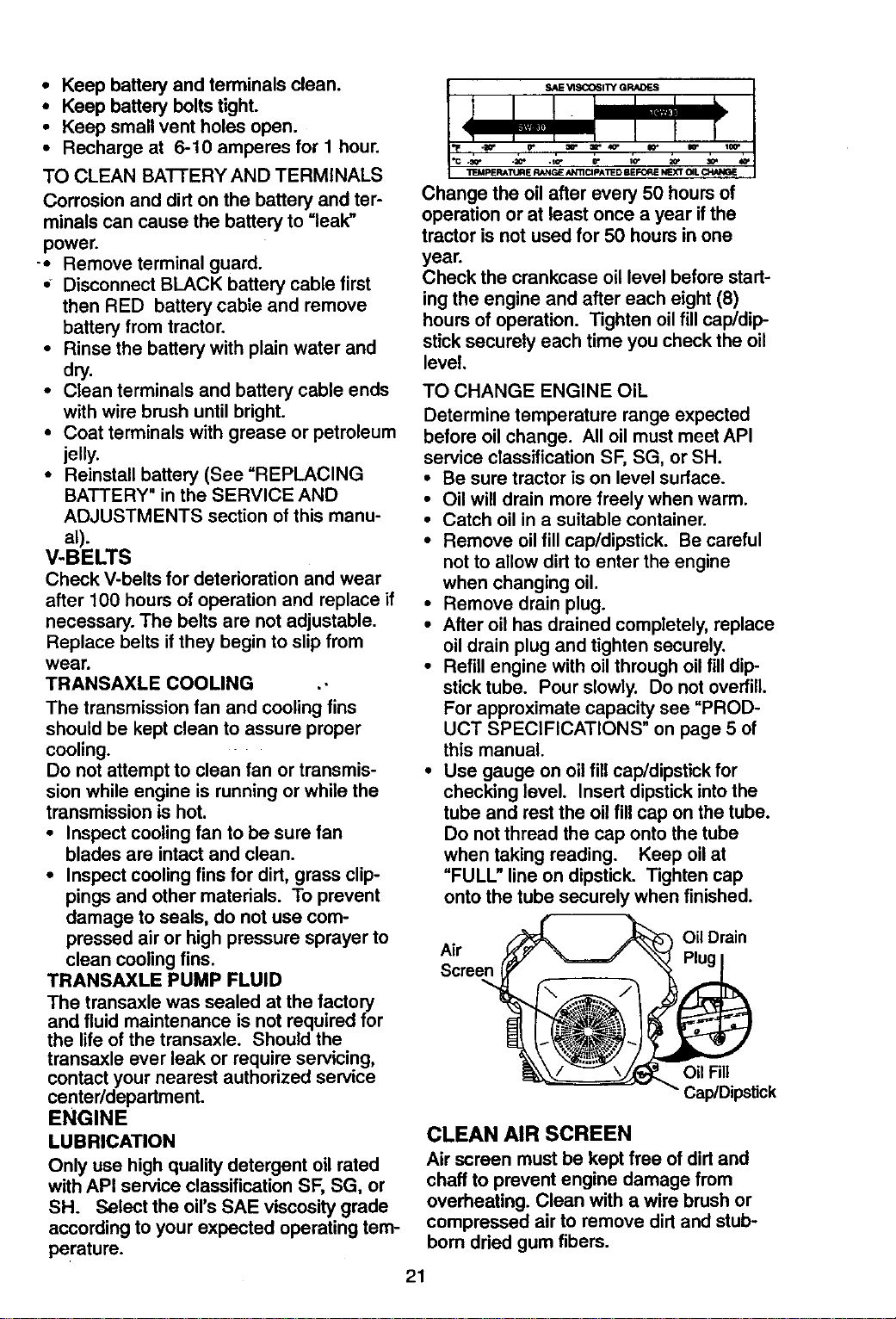
LUBRICATION
Only use high quality detergent oil rated
with API service classification SF, SG, or
SH. Select the oil's SAE viscosity grade
according to your expected operating tem-
perature.
SAE VISCOSITY GRADES
_G .:Q, 40. .IG- r IG"
_J_lP ERATt .iFIE RANGE/_TIC;pATED BEFORE NEXT OiL C_ANGE
Change the oil after every 50 hours of
operation or at least once a year if the
tractor is not used for 50 hours in one
year.
Check the crankcase oil level before start-
ing the engine and after each eight (8)
hours of operation. Tighten oilfill cap/dip
stick securely each time you check the oil
level.
TO CHANGE ENGINE OiL
Determine temperature range expected
before oil change. All oil must meet API
service classification SF, SG, or SH.
• Be sure tractor is on level surface.
• Oil will drain more freely when warm.
• Catch oil in a suitable container.
• Remove oil fill cap/dipstick. Be careful
not to allow dirt to enter the engine
when changing oil.
• Remove drain plug.
• After oil has drained completely, replace
oil drain plug and tighten securely.
• Refill engine with oil through oil fill dip-
stick tube. Pour slowly. Do not overfill.
For approximate capacity see "PROD-
UCT SPECIFICATIONS" on page 5 of
this manual.
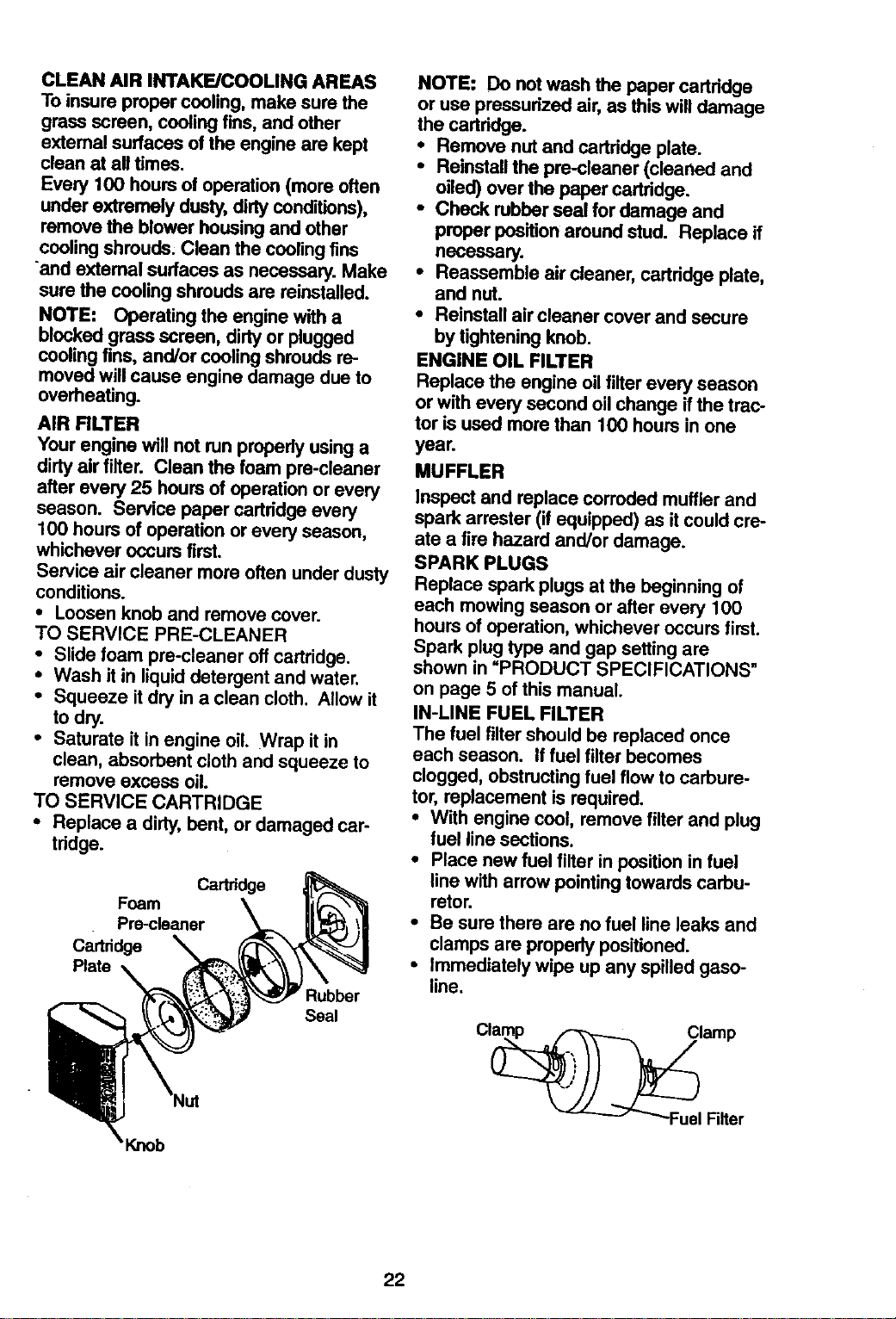
• Use gauge on oil fill cap/dipstick for
checking level. Insert dipstick into the
tube and rest the oil fill cap on the tube.
Do not thread the cap onto the tube
when taking reading. Keep oil at
"FULL" line on dipstick. Tighten cap
onto the tube securely when finished.
Air
Screen
Oil Drain
Oil Fill
Cap/Dipstick
CLEAN AIR SCREEN
Air screen must be kept free of dirt and
chaff to prevent engine damage from
overheating. Clean with a wire brush or
compressed air to remove dirt and stub-
born dried gum fibers.
21
CLEANAIRINTAKFJCOOUNGAREAS
Toinsurepropercooling,makesurethe
grassscreen,coolingfins,andother
externalsurfacesoftheenginearekept
cleanat all times.
Every 100 hours of operation (more often
under extremely dusty, dirty cenditJons),
remove the blower housing and other
cooling shrouds. Clean the cooling fins
and external surfaces as necessary. Make
sure the cooling shrouds are reinstalled.
NOTE: Operating the engine with a
blocked grass screen, dirty or p_ugged
cooling fins, and/or cooling shrouds re-
moved will cause engine damage due to
overheating.
AIR RLTER
Your engine will not run properly using a
dirty air filter. Clean the foam pre-cleaner
after every 25 hours of operation or every
season. Service paper cartddge every
100 hours of operation or every season,
whichever occurs first.
Service air cleaner more often under dusty
conditions.
• Loosen knob and remove cover.
TO SERVICE PRE-CLEANER
• Slide loam pre-cleaner off cartridge.
• Wash it in liquid detergent and water.
• Squeeze it dry in a clean cloth. Allow it
to dry.
• Saturate it in engine oil. Wrap it in
clean, absorbent cloth and squeeze to
remove excess oil.
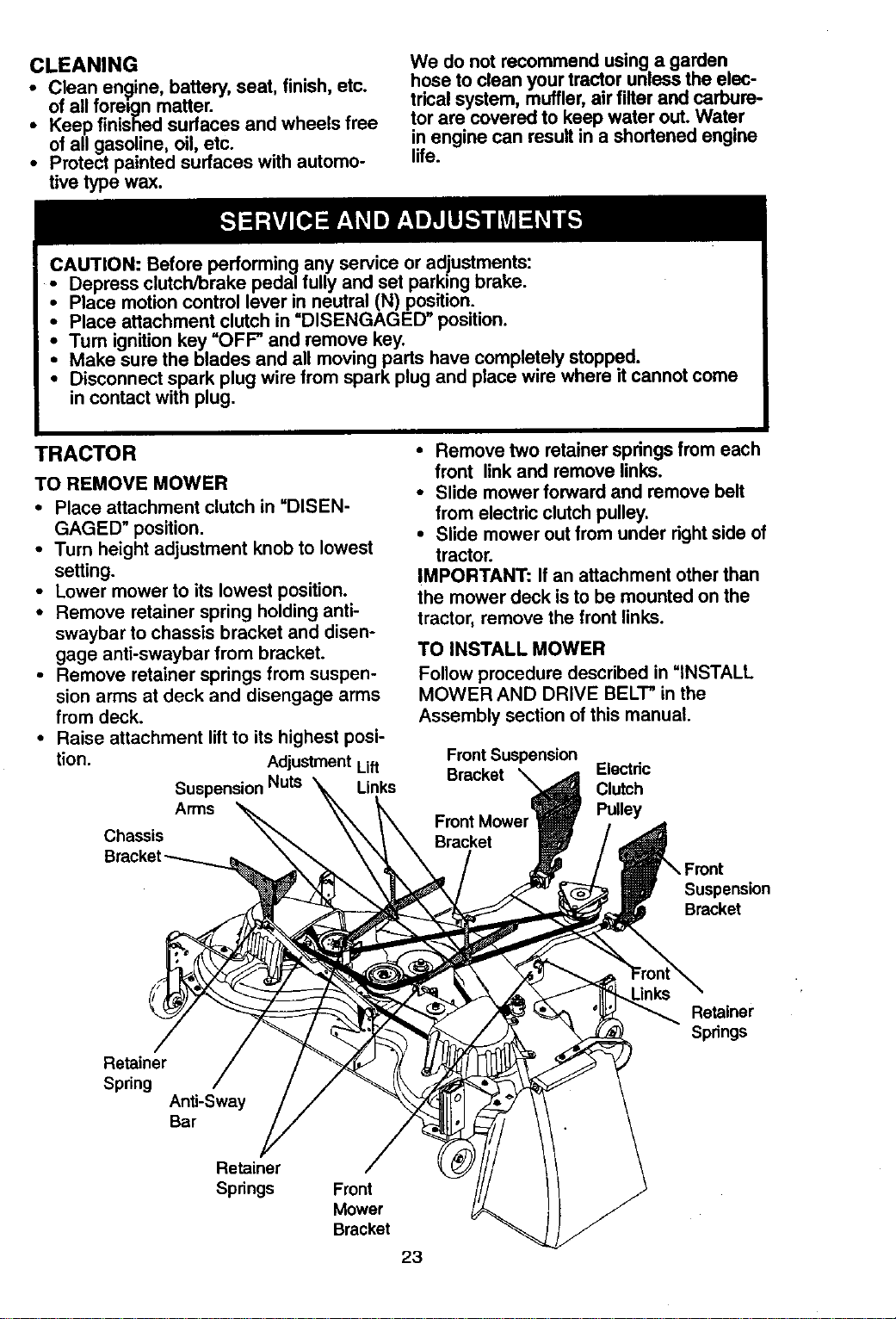
TO SERVICE CARTRIDGE
• Replace a dirty, bent, or damaged car-
tridge.
Cadddge
Foam
Prs-cleaner
Ca_ddge
Plate
Rubber
Seal
NOTE: Do not wash the paper cartridge
or use pressurized air, as this will damage
the cartddge.
• Remove nut and cartridge plate.
• Reinstall the pre-cleaner (cleaned and
oiled) over the paper cartridge.
• Check rubber seal for damage and
proper position around stud. Replace if
necessary.
• Reassemble air cleaner, cartridge plate,
and nut.
• Reinstall air cleaner cover and secure
by tightening knob.
ENGINE OIL FILTER
Replace the engine oil filter every season
or with every second oil change if the trac-
tor is used more than 100 hours in one
yea_
MUFFLER
Inspect and replace corroded muffler and
spark arrester (if equipped) as it could cre-
ate a fire hazard and/or damage.
SPARK PLUGS
Replace spark plugs at the beginning of
each mowing season or after every 100
hours of operation, whichever occurs first.
Spark plug type and gap setting are
shown in "PRODUCT SPECIFICATIONS"
on page 5 of this manual.
IN-LINE FUEL FILTER
The fuel filter should be replaced once
each season. If fuel filter becomes
clogged, obstructing fuel flow to carbure-
tor, replacement is required.
• With engine cool, remove filter and plug
fuel line sections.
• Place new fuel filter in position in fuel
line with arrow pointing towards carbu-
retor.
• Be sure there are no fuel line leaks and
clamps are properly positioned.
• Immediately wipe up any spilled gaso-
line.
22
CLEANING
Clean engine, battery, seat, finish, etc.
_of all matter.
foreign
Keep finished surfaces and wheels free
of all gasoline, oil, etc.
• Protect painted surfaces with automo-
tive type wax.
We do not recommend using a garden
hose to clean your tractor unless the elec-
trical system, muffler, air filter and carbure-
tor are covered to keep water out. Water
in engine can result in a shortened engine
life.
CAUTION: Before performing any service or adjustments:
• Depress clutch/brake pedal fully and set parking brake.
• Place motion control lever in neutral (N) position.
• Place attachment clutch in =DISENGAGED position.
Tum ignition key "OFF" and remove key.
Make sure the blades and all moving parts have completely stopped.
Disconnect spark plug wire from spark plug and place wire where it cannot come
in contact with plug.
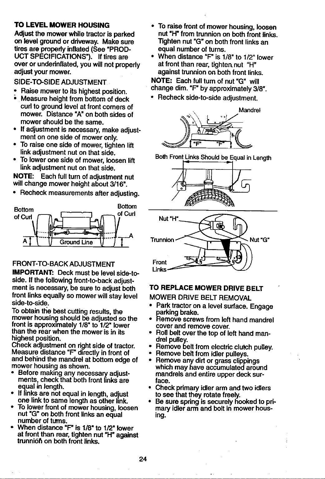
TRACTOR
TO REMOVE MOWER
• Place attachment clutch in =DISEN-
GAGED" position.
• Turn height adjustment knob to lowest
setting.
• Lower mower to its lowest position.
• Remove retainer spring holding anti-
swaybar to chassis bracket and disen-
gage anti-swaybar from bracket.
• Remove retainer springs from suspen-
sion arms at deck and disengage arms
from deck.
• Raise attachment lift to its highest posi-
tion. Adjustment Lift
Suspension Nuts Links
Arms
Chassis
• Remove two retainer springs from each
front link and remove links.
• Slide mower forward and remove belt
from electric clutch pulley.
• Slide mower out from under right side of
tractor.
IMPORTANT: If an attachment other than
the mower deck is to be mounted on the
tractor, remove the front links.
TO INSTALL MOWER
Follow procedure described in "iNSTALL
MOWER AND DRIVE BELT" in the
Assembly section of this manual.
Front Suspension
Bracket Electric
Clutch
Pulley
Suspension
Bracket
Retainer
Spring
Anti-Sway
Bar
Retainer
Springs
Retainer
Spdngs Fm_
Mower
Bracket
23
TO LEVEL MOWER HOUSING
Adjust the mower while tractor is perked
on level ground or driveway. Make sure
tires are propedy inflated (See =PROD-
UCT SPECIFICATIONS"). If tires are
over or undednflated, you will not properly
adjust your mower.
SIDE-TO-SIDE ADJUSTMENT
• Raise mower to its highest position.
;, Measure height from bottom of deck
cud to ground level at front corners of
mower. Distance =A" on both sides of
mower should be the same.
• If adjustment is necessary, make adjust-
ment on one side of mower only.
• To raise one side of mower, tighten lift
link adjustment nut on that side.
• To lower one side of mower, loosen lift
link adjustment nut on that side.
NOTE: Each full turn of adjustment nut
will change mower height about 3/16".
• Recheck measurements after adjusting.
Bottom
Bottom
of Cud\(_-(___'_ f Curl
FRONT-TO-BACK ADJUSTMENT
IMPORTANT: Deck must be level side-to-
side. If the following front-to-back adjust-
ment is necessary, be sure to adjust both
front links equally so mower will stay level
side-to-side.
To obtain the best cutting results, the
mower housinc.:jshould be adjusted so the
front is approximately 1/8" to 1/2" lower
than the rear when the mower is in its
highest position.
Check adjustment on right side of tractor.
Measure distance =P directly in front of
and behind the mandrel at bottom edge of
mower housing as shown.
• Before making any necessary adjust-
ments, check that both front links are
equal in length.
If links are not equal in length, adjust
one link to same length as other link.
To lower front of mower housing, loosen
nut =(3" on both front links an equal
number of turns.
• When distance "P is 1/8" to 1/2" lower
at front than rear, tighten nut "H" against
trunni6_ on both front links.
• To raise front of mower housing, loosen
nut "H" from trunnion on both front links.
Tighten nut "G" on both front links an
equal number of turns.
• When distance "P is 1/8" to 1/2" lower
at front than rear, tighten.nut "H"
against trunnion on both front links.
NOTE: Each full turn of nut =G" will
change dim. =P by approximately 3/8".
• Recheck side-to-side adjustment.
Mandrel
Both F_Length
Nut "H*_
Trunnion/_ Nut "G"
Links_
TO REPLACE MOWER DRIVE BELT
MOWER DRIVE BELT REMOVAL
• Park tractor on a level surface. Engage
parking brake.
• Remove screws from left hand mandrel
cover and remove cover.
• Roll belt over the top of left hand man-
drel pulley.
• Remove belt from electdc clutch pulley.
• Remove belt from idler pulleys.
Remove any dirt or grass clippings
which may have accumulated around
mandrels and entire upper deck sur-
face.
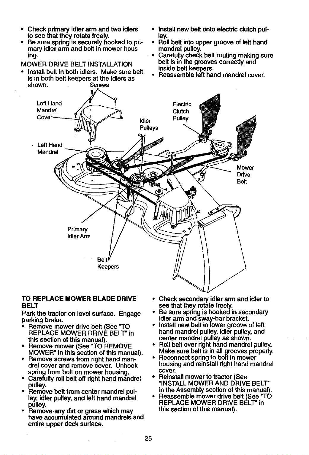
Check primary idler arm and two idlers
to that rotate freely.
see
they
Be sure spring is securely hooked to pri-
mary idler arm and bolt in mower hous-
ing.
24
• Check primary idler arm and two idlers
to see that they rotate freely.
• Be sure spring is securely hooked to pri-
mary idler arm and bolt in mower hous-
ing.
MOWER DRIVE BELT INSTALLATION
• Install belt in both idlers. Make sure belt
is in both belt keepers at the idlers as
shown. Screws
• Install new belt onto electric clutch pul-
ley.
• Roll belt into upper groove of left hand
mandrel pulley.
• Carefully check belt routing making sure
belt is in the grooves correctly and
inside belt keepers.
• Reassemble left hand mandrel cover.
Left Hand
Mandrel
Idler
Pulleys
Eiectdc
Clutch
Pulley
• Left Hand
Mandrel
Mower
Drive
Belt
Primary
Idler Arm
BeltJ
Keepers
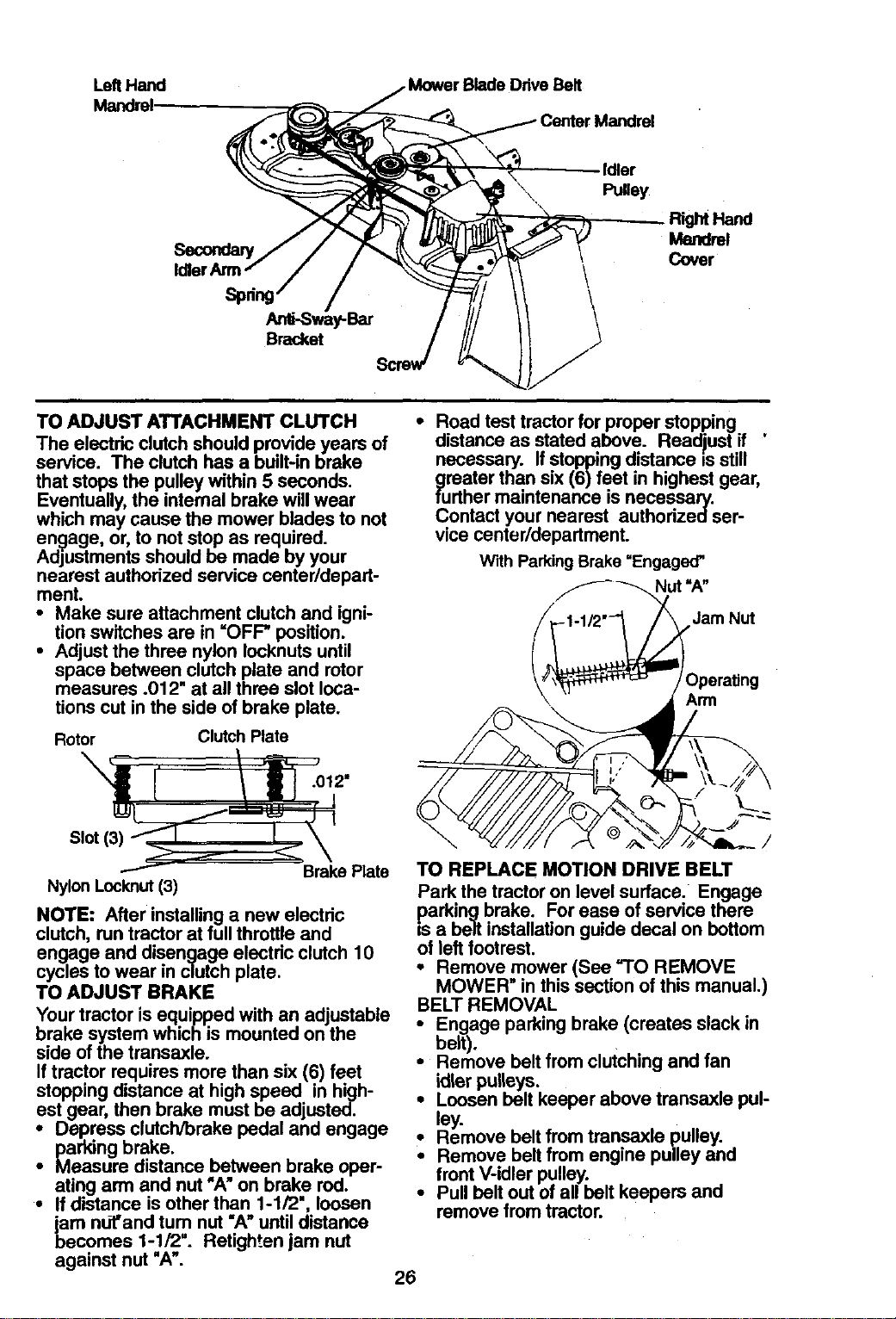
TO REPLACE MOWER BLADE DRIVE
BELT
Park the tractor on level surface. Engage
parking brake.
• Remove mower drive belt (See "TO
REPLACE MOWER DRIVE BELT" in
this section of this manual).
• Remove mower (See =TO REMOVE
MOWER" in this section of this manual).
• Remove screws from right hand man-
drel cover and remove cover. Unhook
spring from bolt on mower housing.
• Carefully roll belt off right hand mandrel
pulley.
i emove belt from center mandrel pul-
ley, idler pulley, and left hand mandrel
pulley.
Remove any dirt or grass which may
have accumulated around mandrels and
entire upper deck surface.
• Check secondary idler arm and idler to
see that they rotate freely.
i e sure spring is hookedin secondary
idler arm and sway-bar bracket.
Install new belt in lower groove of left
hand mandrel pulley, idler pulley, and
center mandrel pulley as shown.
i oll belt over right hand mandrel pulley.
Make sure belt is in all grooves properly.
Reconnect spring to bolt in mower
housing and reinstall right hand mandrel
cover.
• Reinstall mower to tractor (See
=INSTALL MOWER AND DRIVE BELT"
in the Assembly section of this manual).
• Reassemble mower drive belt (See =TO
REPLACE MOWER DRIVE BELT" in
this section of this manual).
25
LeftHand .MowerBlade DriveBelt
Mandrel-
Idle
Idler
Pulley
Mandrel
Cover
Bracket
TO ADJUST ATTACHMENT CLUTCH
The electric clutch should provide years of
service. The clutch has a built-in brake
that stops the pulley within 5 seconds.
Eventually, the internal brake will wear
which may cause the mower blades to not
engage, or, to not stop as required.
Adjustments should be made by your
nearest authorized service center/depart-
ment.
• Make sure attachment clutch and igni-
tion switches are in =OFP position.
• Adjust the three nylon Iocknuts until
space between clutch plate and rotor
measures .012" at all three slot loca-
tions cut in the side of brake plate.
Rotor Clutch Rate
.012"
Slot
Brake Plate
Nylon Locknut (3)
NOTE: After installing a new electric
clutch, run tractor at full throttle and
engage and disengage electdc clutch 10
cycles to wear in clutch plate.
TO ADJUST BRAKE
Your tractor isequipped with an adjustable
brake system which is mounted onthe
side of the transaxle.
Iftractor requires more than six (6) feet
stopping distance at highspeed in high-
est gear, then brake must be adjusted.
• Depress clutch/brake pedal and engage
• parking brake.
Measure distance between brake oper-
ating arm and nut "A"on brake rod.
• If distance isother than 1-1/2", loosen
jam ndf'and tum nut "A"until distance
becomes 1-1/2". Retighten jam nut
against nut "A'.
• Road test tractor for proper stopping ,
distance as stated above. Readiust if
necessary. If stopping distance is still
greatar than six (6) feet in highest gear,
further maintenance is necessary.
Contact your nearest authodzedser-
vice center/department.
With Parking Brake "Engaged"
"A-
Jam Nut
)perating
\ Arm
/
TO REPLACE MOTION DRIVE BELT
Park the tractor on level surface. Engage
parking brake. For ease of service there
is a belt installation guide decal on bottom
of left footrest.
• Remove mower (See "TO REMOVE
MOWER" in this section of this manual.)
BELT REMOVAL
• Engage parking brake (creates slack in
belt).
• Remove belt from clutching and fan
idler pulleys.
• Loosen belt keeper above transaxle pul-
ley.
Remove belt from transaxle pulley.
Remove belt from engine pulley and
front V-idler pulley.
• Pull belt out of all belt keepers and
remove from tractor.
26
= •
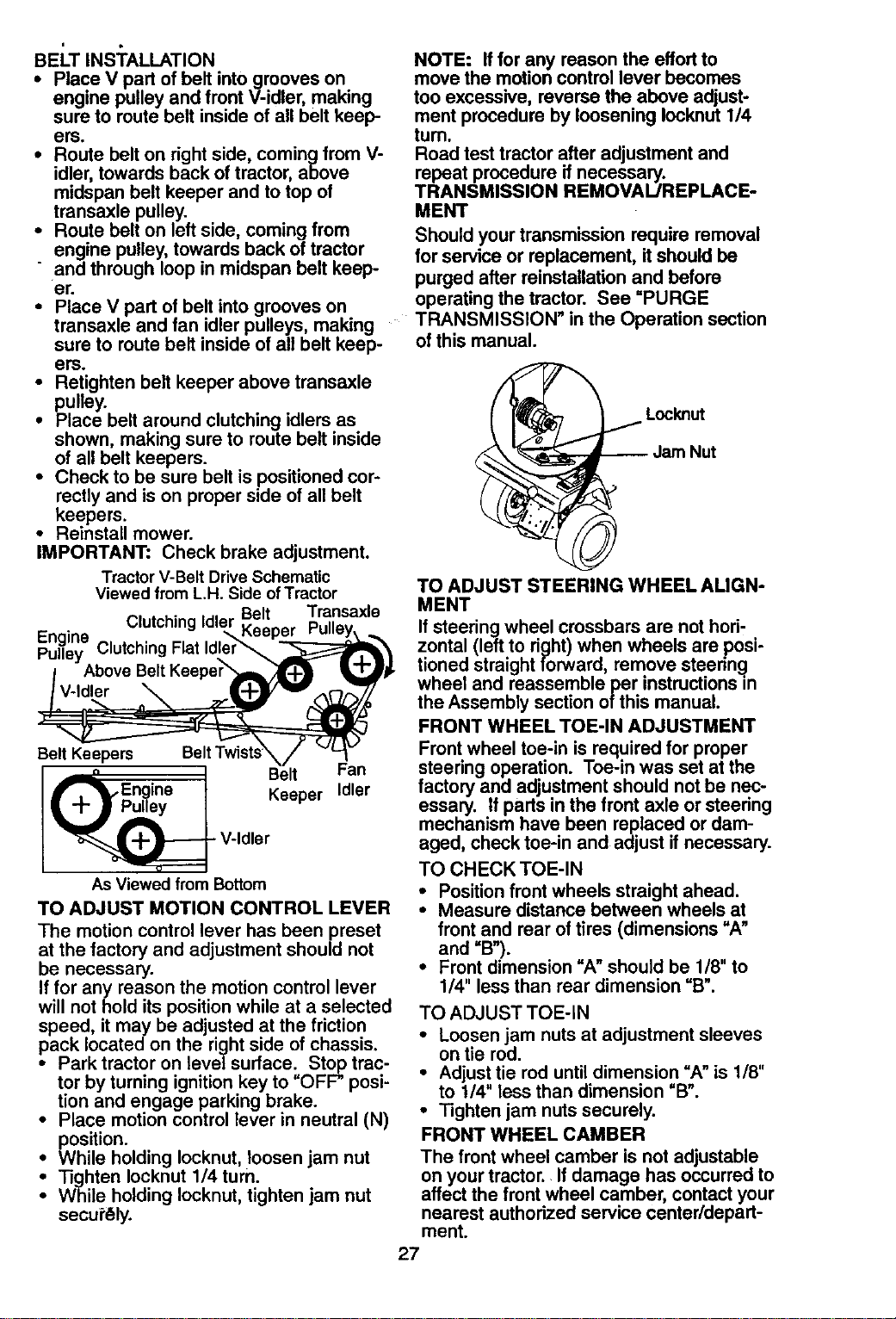
BELT INSTALLATION
• Place V part of belt intogrooves on
engine pulley and front V-idler, making
sure to route belt inside of all belt keep-
ers.
• Route belt on right side, coming from V-
idler, towards back of tractor, above
midspan belt keeper and to top of
transaxle pulley.
• Route belt on left side, coming from
engine pulley, towards back of tractor
" and through loop in midspan belt keep-
er.
• Place V part of belt into grooves on
transaxle and fan idler pulleys, making
sure to route belt inside of all belt keep-
are.
• Retighten belt keeper above transaxle
pulley.
• Place belt around clutching idlers as
shown, making sure to route belt inside
of all belt keepers.
• Check to be sure belt is positioned cor-
rectly and is on proper side of all belt
keepers.
• Reinstall mower.
IMPORTANT: Check brake adjustment.
Tractor V-Belt DriveSchematic
Viewed from L.H. Side ofTractor
Belt Transaxle
Clutching Idler Keeper
Engine Clutching Flat Idler_
Pulley
Above
V-Idler
Belt Keepers
Belt Fan
• Keeper Idler
V-Idler
As Viewed from Bottom
TO ADJUST MOTION CONTROL LEVER
The motion control lever has been preset
at the factory and adjustment should not
be necessary.
If for any reason the motion control lever
will not hold its position while at a selected
speed, it may be adjusted at the friction
pack located on the right side of chassis.
• Park tractor on level surface. Stop trac-
tor by turning ignition key to "OFF" posi-
tion and engage parking brake.
• Place motion control lever in neutral (N)
position.
• While holding Iocknut, loosen jam nut
• Tighten Iocknut 1/4 turn.
While holding Iocknut, tighten jam nut
secu_'_ly.
NOTE: If for any reason the effort to
move the motion control lever becomes
too excessive, reverse the above adjust-
ment procedure by loosening Iocknut 1/4
turn.
Road test tractor after adjustment and
repeat procedure if necessary.
TRANSMISSION REMOVAL/REPLACE-
MENT
Should your transmission require removal
for service or replacement, it should be
purged after reinstallationand before
operatingthe tractor. See "PURGE
TRANSMISSION" in the Operation section
ofthis manual.
Locknut
TO ADJUST STEERING WHEEL AUGN-
MENT
If steering wheel crossbars are not hori,
zontal (left to right) when wheels are posi-
tioned straight forward, remove steering
wheel and reassemble per instructions in
the Assembly section of this manual.
FRONT WHEEL TOE-IN ADJUSTMENT
Frontwheel toe-in is required for proper
steering operation. Toe-in was set at the
factory and adjustment should not be nec-
essary. If parts in the front axle or steering
mechanism have been replaced or dam-
aged, check toe-in and adjust ifnecessary.
TO CHECK TOE-IN
• Positionfront wheels straight ahead.
• Measure distance between wheels at
front and rear oftires (dimensions "A"
and =B").
• Front dimension"A" should be 1/8" to
1/4" less than rear dimension "B".
TO ADJUST TOE-IN
• Loosen jam nuts at adjustment sleeves
on tie rod.
• Adjust tie rod until dimension "A" is 1/8"
to 114" less than dimension "B".
° Tighten jam nuts securely.
FRONT WHEEL CAMBER
The front wheel camber is not adjustable
on your tractor. If damage has occurred to
affect the front wheel camber, contact your
nearest authorized service center/depart-
ment.
27
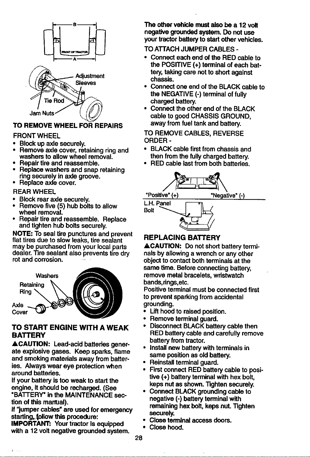
Sleeves
Jam Nuts
TO REMOVE WHEEL FOR REPAIRS
FRONT WHEEL
* Block up axle securely.
Remove axle cover, retaining ring and
washers to allow wheel removal.
• Repair tire and reassemble.
• Replace washers and snap retaining
ring securely in axle groove.
• Replace axle cover.
REAR WHEEL
: Block rear axle securely.
Remove five (5) hub bolts to allow
wheel removal.
• Repair tire and reassemble. Replace
and tighten hub bolts securely.
NOTE: To seal tire punctures and prevent
flat tires due to slow leaks, tire sealant
may be purchased from your local parts
dealer. Tire sealant also prevents tire dry
rot and corrosion.
Washers
Ring
Axle
Cover_
TO START ENGINE WITH A WEAK
BATTERY
&CAUTION: Lead-acid battedes gener-
ate explosive gases. Keep sparks, flame
and smoking materials away from batter-
ies. Always wear eye protection when
around batteries.
Ifyour battery istoo weak to start the
engine, itshould be recharged. (See
=BA'I-I'ERY" in the MAINTENANCE sec-
tion of this marrual).
If=jumper cables" are used for emergency
starting.tollow this procedure:
IMPORTANT: Your tractor Is equipped
with a 12 volt negative grounded system.
The other vehicle must also be a 12 volt
negative grounded system. Do i_ot use
your tractor battery to start other vehicles.
TO ATTACH JUMPER CABLES -
• Connect each end of the RED cable to
the POSITIVE (+) terminal of each bat-
tery, taking care not to short against
chassis.
• Connect one end of the BLACK cable to
the NEGATIVE (-) terminal of fully
charged battery.
• Connect the other end of the BLACK
cable to good CHASSIS GROUND,
away from fuel tank and battery.
TO REMOVE CABLES, REVERSE
ORDER -
• BLACK cable first from chassis and
then from the fully charged battery.
• RED cable last from both batteries.
=Positive"(+) "Negative" (-)
L.H. Panel _t .
Bolt
REPLACING BATTERY
ACAUTION: Do not short battery termi-
nals by allowing a wrench or any other
object to contact both terminals at the
same time. Before connecting battery,
remove metal bracelets, wristwatch
bands,rings,etc.
Positive terminal must be connected first
to prevent sparking from accidental
grounding.
• Lift hood to raised position.
• Remove terminal guard.
• Disconnect BLACK battery cable then
RED battery cable and carefully remove
battery from tractor.
• Instal[ new battew with terminals in
same position as old battery.
• Reinstall terminal guard.
• First connect RED battery cable to posi-
tive (+) battery terminal with hex bolt,
keps nut as shown. "lighten securely.
• Connect BLACK grounding cable to
negative (-) battery terminal with
remaining hex bolt, keps nuL Tighten
securely.
• Close terminal access doors.
• Close hood.
28
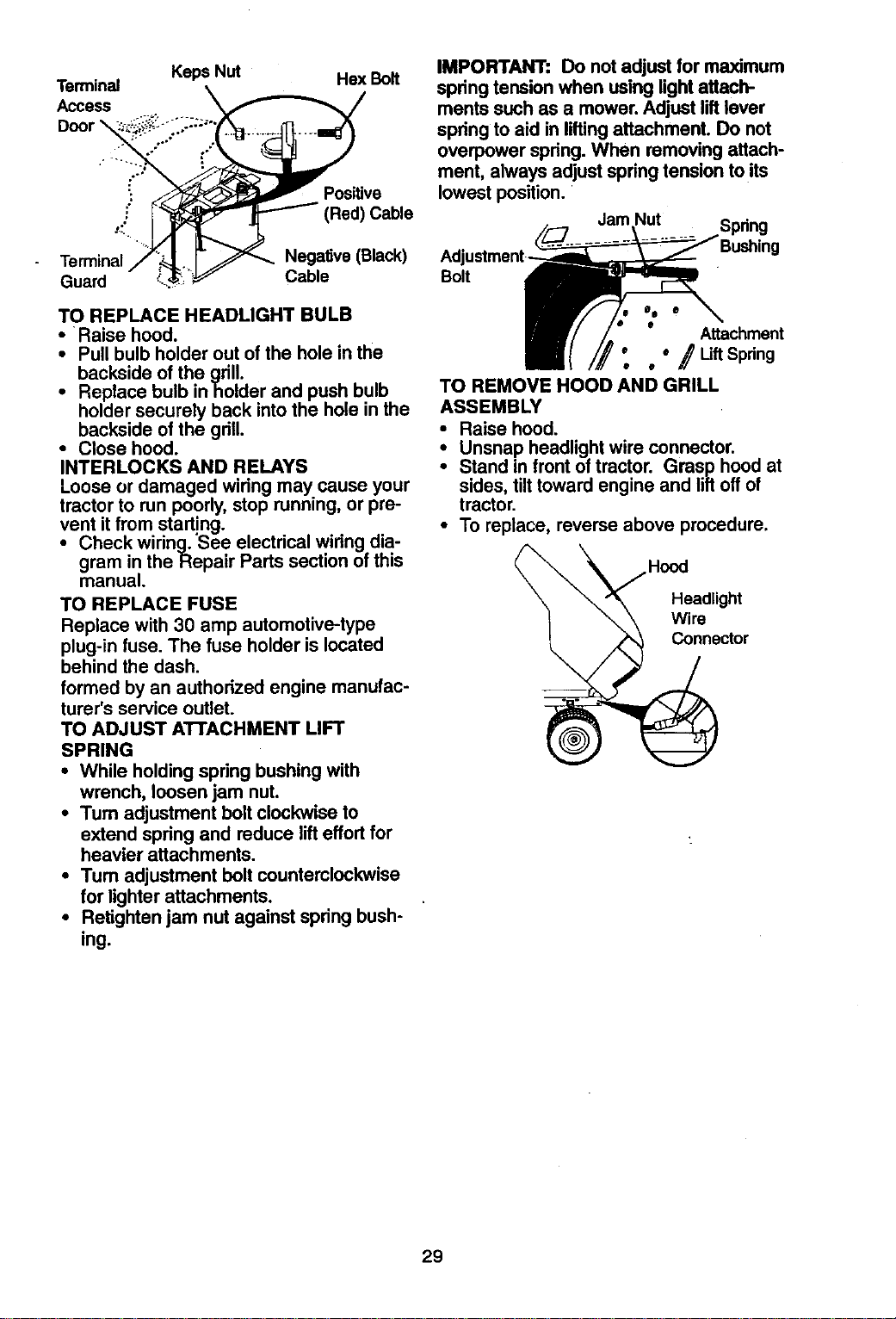
Terminal
Access
Keps Nut Hex Bolt
': Positive
•:" Red) Cable
Terminal Negative (Black)
Guard Cable
TO REPLACE HEADLIGHT BULB
• Raise hood.
• Pull bulb holder out of the hole in the
backside of the grill.
• Replace bulb inholder and push bulb
holder securely back into the hole in the
backside of the grill.
• Close hood.
INTERLOCKS AND RELAYS
Loose or damaged wiring may.cause your
tractor to run poorly, stop running, or pre-
vent it from starting.
• Check wiring. 'See electrical wiring dia-
gram in the Repair Parts section of this
manual.
TO REPLACE FUSE
Replace with 30 amp automotive-type
plug-in fuse. The fuse holder is located
behind the dash.
formed by an authorized engine manufac-
turer's service outlet.
TO ADJUST ATI'ACHMENT LIFT
SPRING
• While holding spring bushing with
wrench, loosen jam nut.
• Turn adjustment bolt clockwise to
extend spring and reduce lift effort for
heavier attachments.
•Tum adjustment bolt counterclockwise
for lighter attachments.
• Retighten jam nut against spring bush-
ing.
IMPORTANT: Do not adjust for maximum
spring tension when using light attach-
ments such as a mower. Adjust lift lever
spring to aid in lifting attachment. Do not
overpower spring. When removing attach-
ment, always adjust spring tension to its
lowest position.
Jam Nut
Bolt
_o •
• e Attachment
' _ •" / LiftSpdng
TO REMOVE HOOD AND GRILL
ASSEMBLY
• Raise hood.
• Unsnap headlight wire connector.
• Stand in front of tractor. Grasp hood at
sides, tilt toward engine and lift off of
tractor.
• To replace, reverse above procedure.
Wire ctor
29
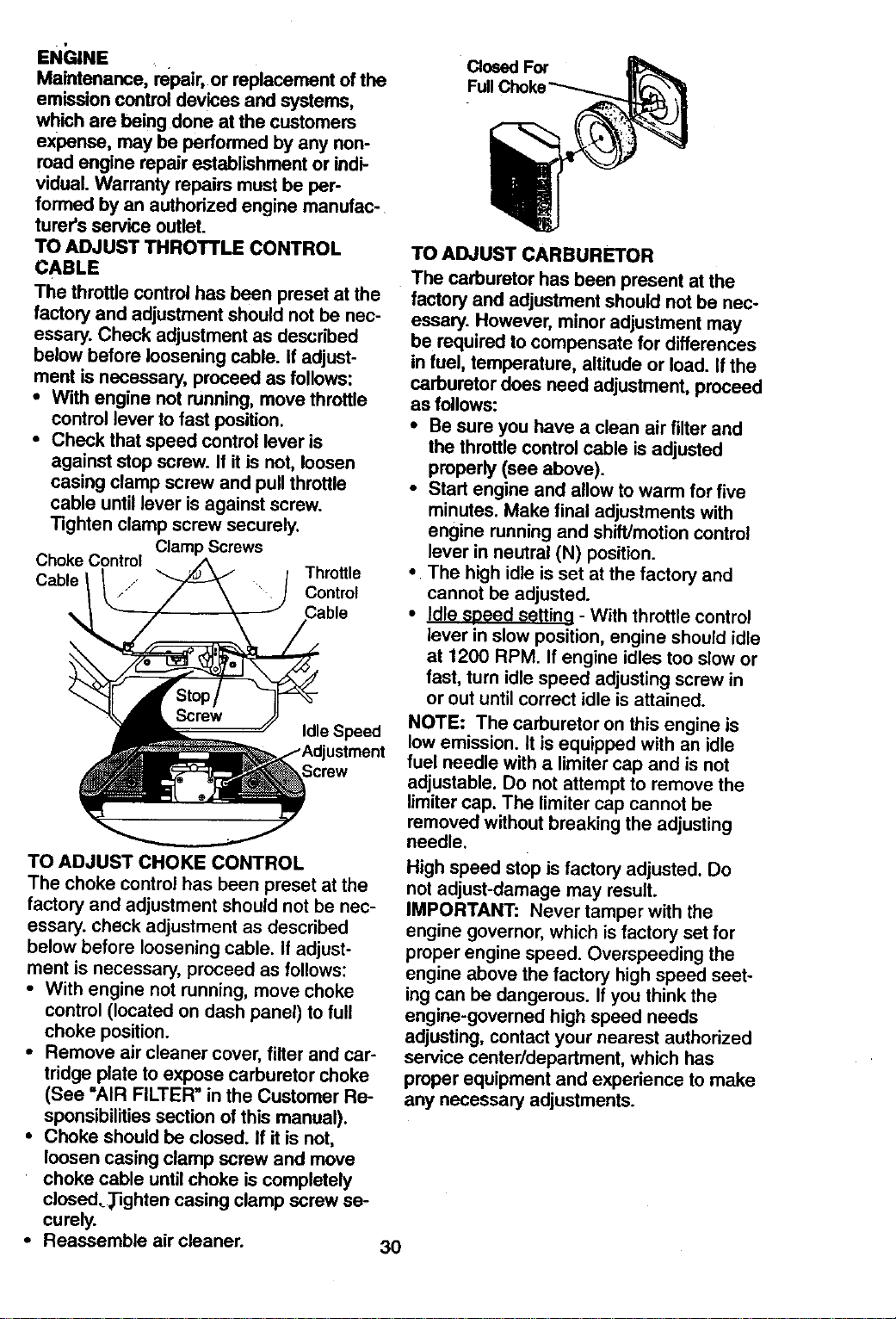
EN_;INE
Maintenance, repair,or replacement of the
emission controldevices and systems,
which are beingdone at the customers
expense, may be performed by any non-
road engine repair establishmentor indi-
vidual. Warranty repairs must be per-
formed by an authorized engine manufac-
turer's service outlet.
TO ADJUST THROTTLE CONTROL
CABLE
The throttle control has been preset at the
factory and adjustment should not be nec-
essary. Check adjustment as described
below before loosening cable. If adjust-
ment is necessary, proceed as follows:
• With engine not running, move throttle
control lever to fast position.
• Check that speed control lever is
against stop screw. If it is not, loosen
casing clamp screw and pull throttle
cable until lever is against screw.
Tighten clamp screw securely.
Clamp Screws
Choke Control
Cable 1 _ Throttle
Control
Idle Speed
TO ADJUST CHOKE CONTROL
The choke control has been preset at the
factory and adjustment should not be nec-
essary, check adjustment as described
below before loosening cable. If adjust-
ment is necessary, proceed as follows:
• With engine not running, move choke
control (located on dash panel) to full
choke position.
• Remove air cleaner cover, filter and car-
tridge plate to expose carburetor choke
(See "AIR FILTER" in the Customer Re-
sponsibilities section of this manual).
• Choke should be closed. If it is not,
loosen casing clamp screw and move
choke cable until choke is completely
closed,_ghten casing clamp screw se-
curely.
• Reassemble air cleaner.
30
Closed For
Full
TO ADJUST CARBURETOR
The carburetor has been present at the
factory and adjustment should not be nec-
essary. However, minor adjustment may
be required to compensate for differences
in fuel, temperature, altitude or load. If the
carburetor does need adjustment, proceed
as follows:
• Be sure you have a clean air filter and
the throttle control cable is adjusted
properly (see above).
• Start engine and allow to warm for five
minutes. Make final adjustments with
engine running and shift/motion control
lever in neutral (N) position.
• The high idle is set at the factory and
cannot be adjusted.
• Idle sDeed setting - With throttle control
lever in slow position, engine should idle
at 1200 RPM. If engine idles too slow or
fast, turn idle speed adjusting screw in
or out until correct idle is attained.
NOTE: The carburetor on this engine is
low emission, it is equipped with an idle
fuel needle with a limiter cap and is not
adjustable. Do not attempt to remove the
limiter cap. The limiter cap cannot be
removed without breaking the adjusting
needle.
High speed stop is factory adjusted. Do
not adjust-damage may result.
IMPORTANT: Never tamper with the
engine governor, which is factory set for
proper engine speed. Overspeeding the
engine above the factory high speed seet-
ing can be dangerous. If you think the
engine-governed high speed needs
adjusting, contact your nearest authorized
service center/department, which has
proper equipment and experience to make
any necessary adjustments.
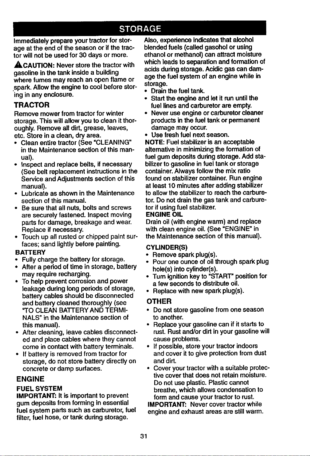
Immediatelyprepareyourtractorforstor-
ageattheendoftheseasonorif thetrac-
torwill notbeusedfor30daysormore.
,_CAUTION: Never store the tractor with
gasoline in the tank inside a building
where fumes may reach an open flame or
.spark. Allow the engine to cool before stor-
ing in any enclosure.
TRACTOR
Remove mower from tractor for winter
storage. This will allow you to clean it thor-
oughly. Remove all dirt, grease, leaves,
etc. Store in a clean, dry area.
• Clean entire tractor (See =CLEANING"
in the Maintenance section of this man-
ual).
• Inspect and replace belts, if necessary
(See belt replacement instructions in the
Service and Adjustments section of this
manual).
• Lubricate as shown in the Maintenance
section of this manual.
• Be sure that all nuts, bolts and screws
are securely fastened. Inspect moving
parts for damage, breakage and wear.
Replace if necessary.
• Touch up all rusted or chipped paint sur-
faces; sand lightly before painting.
BATTERY
• Fully charge the battery for storage.
• After a period of time in storage, battery
may require recharging.
• To help prevent corrosion and power
leakage during long periods of storage,
battery cables should be disconnected
and battery cleaned thoroughly (see
"TO CLEAN BATTERY AND TERMI-
NALS" in the Maintenance section of
this manual).
• After cleaning, leave cables disconnect-
ed and place cables where they cannot
come in contact with battery terminals.
• If battery is removed from tractor for
storage, do not store battery directly on
concrete or damp surfaces.
ENGINE
FUEL SYSTEM
IMPORTANT: It is important to prevent
gum deposits from forming in essential
fuel system parts such as carburetor, fuel
filter, fuel hose, or tank during storage.
Also, experience indicates that alcohol
blended fuels (called gasohol or using
ethanol or methanol) can attract moisture
which leads to separation and formation of
acids during storage. Acidic gas can dam-
age the fuel system of an engine while in
storage.
• Drain the fuel tank.
• Start the engine and let it run until the
fuel lines and carburetor are empty.
• Never use engine or carburetor cleaner
products in the fuel tank or permanent
damage may occur.
• Use fresh fuel next season.
NOTE: Fuel stabilizer is an acceptable
alternative in minimizing the formation of
fuel gum deposits during storage. Add sta-
bilizer to gasoline in fuel tank or storage
container. Always follow the mix ratio
found on stabilizer container. Run engine
at least 10 minutes after adding stabilizer
to allow the stabilizer to reach the carbure-
tor. Do not drain the gas tank and carbure-
tor if using fuel stabilizer.
ENGINE OIL
Drain oil (with engine warm) and replace
with clean engine oil. (See "ENGINE" in
the Maintenance section of this manual).
CYLINDER(S)
• Remove spark plug(s).
• Pour one ounce of oil through spark plug
hole(s) into cylinder(s).
• Turn ignition key to "START" position for
a few seconds to distribute oil.
• Replace with new spark plug(s).
OTHER
• Do not store gasoline from one season
to another.
• Replace your gasoline can if it starts to
rust. Rust and/or dirt in your gasoline will
cause problems.
• if possible, store your tractor indoors
and cover it to give protection from dust
and dirt.
• Cover your tractor with a suitable protec-
tive cover that does not retain moisture.
Do not use plastic. Plastic cannot
breathe, which allows condensation to
form and cause your tractor to rust.
IMPORTANT: Never cover tractor while
engine and exhaust areas are still warm.
31
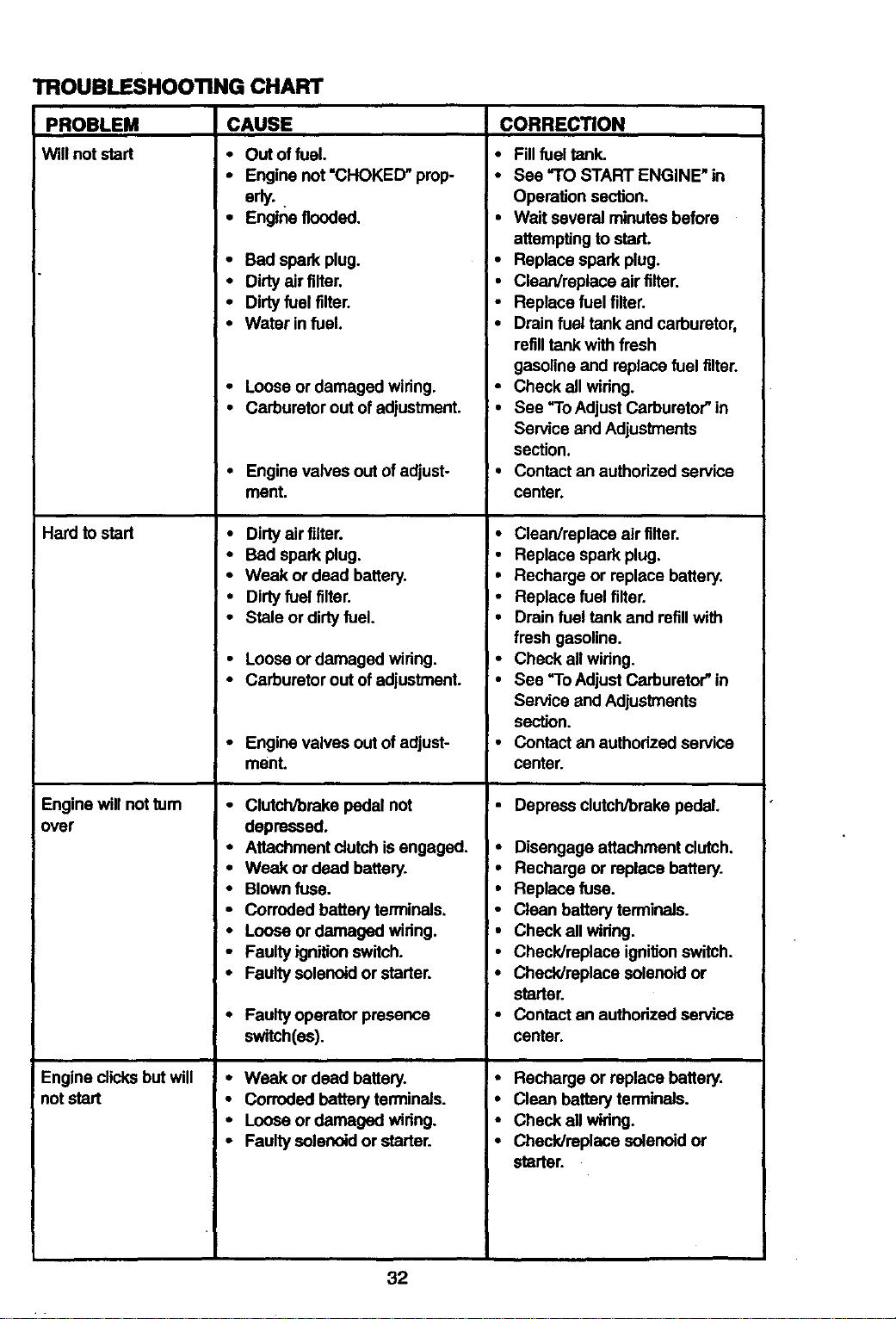
TROUBLESHOOTING CHART
PROBLEM
Will not start
Hard to stad
Engine will not tum
over
Engine dicks but will
not start
CAUSE CORREC_ON
• Out offuel.
• Engine not'CHOKED" prop
eriy.
• Engine flooded.
• Bad spark plug.
• Dirtyair filter.
• Dirtyfuel filter.
• Water infuel.
Loose ordamaged wiring. -
Carburetorout ofadjustment. •
Engine valves out ofadjust- •
ment.
Dirtyair filter. •
Bad spark plug. •
Weak or dead battery. •
Dirtyfuel filter.
Stale or dirtyfuel,
Loose or damaged wiring.
Carburetorout ofadjustment. •
Engine valves outof adjust- •
ment.
Clutch/brake pedal not
depressed.
Attachmentdutch is engaged. •
Weak or dead battery.
Blownfuse.
Corroded battery terminals.
Loose or damaged wiring.
Faultyignitionswitch.
Faultysolenoid or starter. °
Faultyoperator presence
switch(es).
Weak or dead battery. °
Corroded battery terminals. •
Looseor damaged wiring.
Faultysolenoid or starter. •
Fillfuel tank.
See =TOSTART ENGINE" in
Operation section.
Wad several minutesbefore
attempting to start.
Replace spark plug.
Clean/replace air filter.
Replace fuel filter.
Drain fuel tank and carburetor,
refilltankwith fresh
gasoline and replace fuel filter.
Check all wiring.
See =ToAdjust Carburetor"in
Service and Adjustments
section.
Contactan authorized service
center.
Clean/replace air filter.
Replace spark plug.
Recharge or replace battery.
Replace fuel filter.
Drain fuel tank and refillwith
fresh gasoline.
Check all wiring.
See "ToAdjust Carburetor"in
Service and Adjustments
section.
Contactan authorizedservice
center.
Depress clutch/brake pedal.
Disengage attachment clutch,
Recharge or replace battery.
Replace fuse.
Clean battery terminals.
Check all wiring.
Checklreplace ignifionswitch.
Checklreplace solenoid or
starter.
Contact an authorized service
center.
Recharge or replace battery.
Clean battery terminals.
Check all wiring.
Check/replace solenoid or
starter.
32
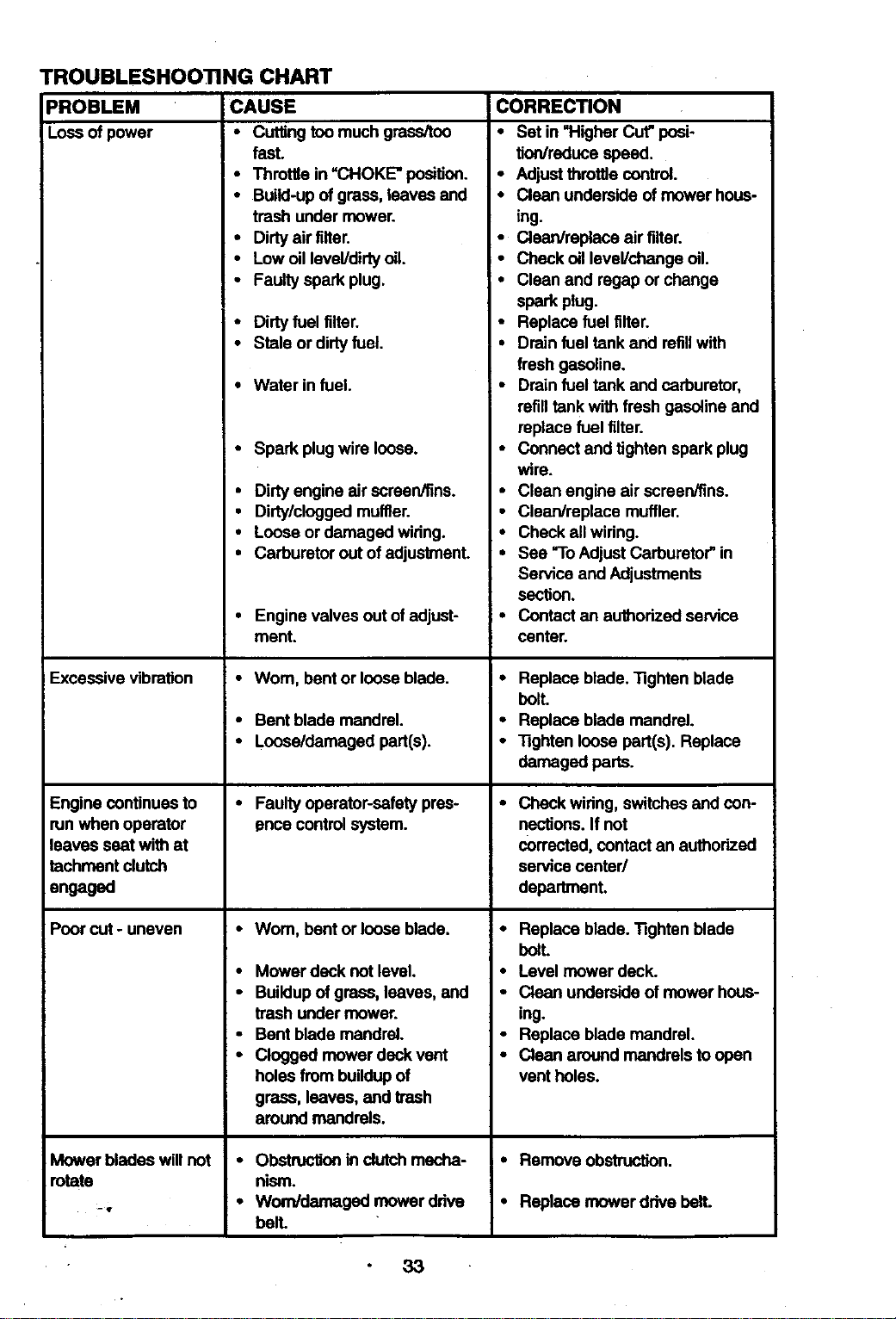
TROUBLESHOOTING CHART
_ROBLEM
Loss of power
CAUSE
• Cuttingtoo much grass/too
fast.
• Throttle in =CHOKE" positioo.
• Build-upof gross, leaves and
trash under mower.
• Dirtyair filter.
• Low oillevel/dirty oil.
• Faultyspark plug.
• Dirtyfuel filter.
• Stele or dirtyfuel.
• Water in fuel.
Excessive vibration
Engine continuesto
runwhen operator
leaves seat with at
techment clutch
engaged
Poor cut - uneven
Mower blades will not
mtete
• Spark plug wire loose.
CORRECTION
• Set in "Higher Cut"posi-
fion/reducespeed.
• Adjustthrottle control.
• Clean underside of mower hous-
ing.
• Clean/replace air tilter.
• Check oil level/change oil.
• Clean and regap or change
spark plug.
• Replace fuel tilter.
• Drain fuel tank and refillwith
fresh gasoline.
• Drain fuel tank and carburetor,
refilltank with fresh gasoline and
replace fuel tilter.
• Connect and tighten spark plug
wire.
Clean engine air screen/tins.
Clean/replece muffler.
Check all wiring.
See "ToAdjust Carburetor"in
Service and Adjustments
section.
• Contact an authodzed service
center.
• Dirty engine air screen/tins. •
• Dirty/cloggedmuffler.
• Loose or damaged wiring.
• Carburetor out of adjustment. •
• Engine valves out of adjust-
ment.
•Wom, bent or loose blade.
• Bent blade mandrel.
• Loose/damaged part(s).
• Faultyoperator-safety pres-
ence controlsystem.
•Wom, bent or loose blade,
• Mower deck not level.
• Buildupof grass, leaves, and
trash under mower.
• Bent blade mandrel.
• Clogged mower deck vent
holes from buildupof
grass, leaves, and trash
around mandrels.
• Obstructionin clutchmecha-
nism.
• Worn/damaged mower drive
bell
• Replace blade. Tighten blade
bolt.
• Replace blade mandrel.
• Tighten loose part(s). Replace
damaged parts.
Check wiring, switches and con-
nections,If not
corrected, contact an authorized
service center/
department,
• Replace blade. Tighten blade
boll
• Level mower deck.
• Clean underside of mower hous-
ing.
• Replace blade mandrel.
• Clean around mandrels toopen
vent holes.
• Remove ob_n.
• Replace mower drive belt.
33
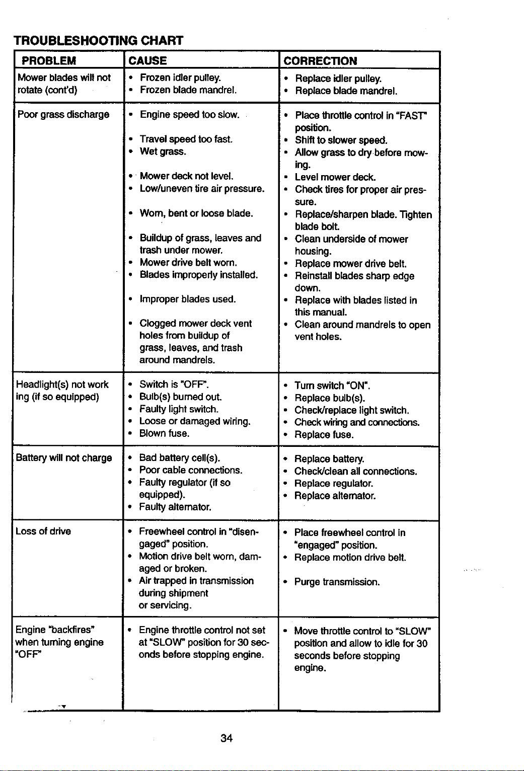
TROUBLESHOOTING CHART
PROBLEM
Mower blades willnot
rotate (coot'd)
Poorgrass discharge
Headlight(s) not work
ing (ifso equipped)
Battery willnot charge
Loss ofddve
Engine=backfires"
when_ming engine
=OFP
CAUSE
• Frozen idler pulley.
• Frozen blade mandrel.
• Engine speed too slow.
• Travel speed too fast.
• Wet grass.
• Mower deck not level.
• Low/uneven tireair pressure.
• Worn, bent or loose blade.
• Buildupof grass,leaves and
trash under mower.
• Mower drivebelt worn.
• Blades improperlyinstalled.
• Improper blades used.
• CIoggedmowerdeck vent
holesfmmbuiidupof
grass, leaves, andtrash
aroundmandrels.
• Switch is "OFF".
• Bulb(s) burnedout.
• Faulty lightswitch.
• Looseor damaged wiring.
• Blownfuse.
• Bad battery cell(s).
• Poorcable connections.
• Faulty regulator(ifso
equipped).
• Faultyalternator.
• Freewheel controlin"disen-
gaged" position.
• Motion drive belt worn, dam-
aged or broken.
• Airtrapped in transmission
during shipment
or servicing.
• Engine throttlecontrolnot set
at "SLOW" positionfor 30 sec-
onds before stoppingengine.
CORRECTION
i• Replace idlerpulley.
• Replace blade mandrel.
• Place throttle controlin=FAST"
position.
:• Shift to slowerspeed.
• Allow grass to dry befora mow-
ing.
• Level mower deck.
• Check tires for properair pres-
sure.
• Replace/sharpen blade. Tighten
blade bolt.
• Clean underside of mower
housing.
• Replace mower drive belt.
• Reinstall blades sharpedge
down.
• Replace with blades listedin
this manual.
• Clean aroundmandrels toopen
vent holes.
• Turn switch=ON'.
• Replace bulb(s).
• Check/replace lightswitch.
• Checkwidng and connections.
• Replace fuse.
• Replace battery.
• Check/clean all connections.
• Replace regulator.
• Replace alternator.
• Place freewheel controlin
"engaged" position.
• Replace motionddve belt.
• Purge transmission.
• Move throttle controlto =SLOW"
positionand allowto idlefor 30
seconds before stopping
engine.
34
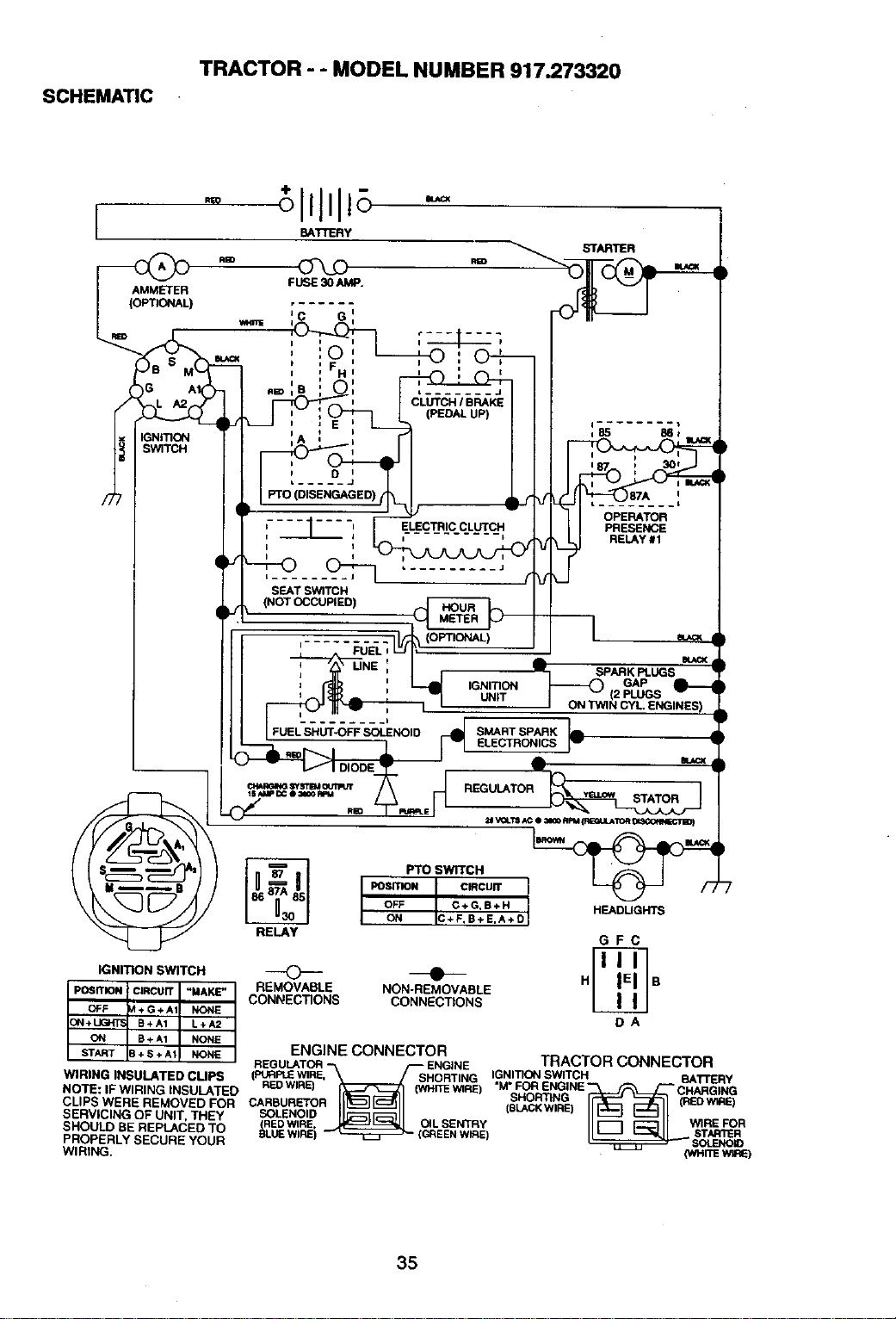
SCHEMATIC
TRACTOR - - MODEL NUMBER 917.273320
RED
l BATTERY
STARTLER
,S5 B61 ._¢X
h t" 87A 'i
....... t
, _ , ELECTRIC CLUTCH PRESENCE
t I
L_.
SEAT SWITCH
{NOT OCCUPIED)
_. _ _ L__ (OPTIONAL) -_ =
FUEL I : i.
, UNE i 'mr SPARK pPLUGS
4L
V
c_mm_ _ts't_ oun._ REGULATOR
Pro SWITCH
I,o=.oNI
OFF C + G,B + H HEADUGHTS
ON IC+F,B+ ErA+Ol
RELAY G F C
IGNITION SWITCH _ _ HII ;El I
B
REMOVABLE NON-REMOVABLE
CONNECTIONS CONNECTIONS
DA
ENGINE CONNECTOR ...............
REGULATOR ENGINE /HAL,/UI-t WI_IP4 C'._/url
Pt,_PLE WIRE,_HORTING IGNITION SWITCH_ BA"/'FERY
WIRING INSULATED CUPS
( RED WIRE) (WHITEWIRE) "M" FOR ENGINE CHARGING
NO'DE: IF WIRING INSULA'('EO I("_--_1 '" SHORTING I¢"JE_ :_]L-_ _ W_qE_
o o.w°.
CLIPS WERE REMOVED FOR _LEwNO/D" WIRE FOR
SERVICING OF UNIT, THEY , ST,_IllE
SHOULD SE REPLACEO TO _LUE WIRE) EENWIRE) SOLENO_
PROPERLY SECURE YOUR tz:_] (WHITEW_E)
WIRING.
35
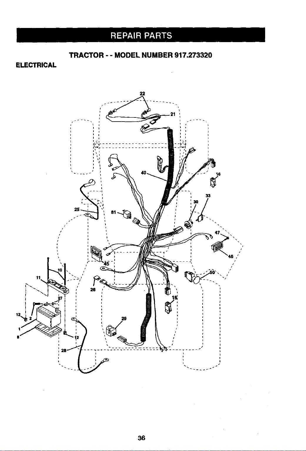
ELECTRICAL
TRACTOR - - MODEL NUMBER 917.273320
22
29
16
33
L
i
I
i
/
46 ,'"
i I
/
r
_j
36
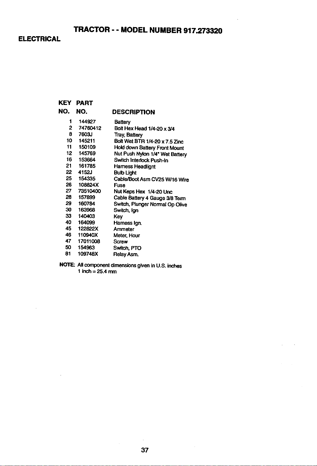
ELECTRICAL
TRACTOR - - MODEL NUMBER 917.273320
KEY
NO.
PART
NO. DESCRIPTION
1 144927 Battery
2 74760412 BoltHex Head 1/4-20 x 3/4
8 7603J Tray,Battery
10 145211 Bolt Wet BTR 114-20x7.5 Zinc
11 150109 HolddownBattery FrontMount
12 145769 Nut PushNylon 1/4°Wet Battery
16 153664 SwitchInterlockPush-In
21 161785 HarnessHeadlignt
22 4152J BulbLight
25 154335 CableJBootAsm CV25 W/16 Wire
26 108824X Fuse
27 73510400 NutKept;Hex 1/4-20 Unc
28 157899 Cable Battery 4 Gauge 3/8 Term
29 160784 Switch,PlungerNormalOp Olive
30 163968 Switch,Ign
33 140403 Key
40 164(}99 HarnessIgn.
45 122822X Ammeter
46 110940X Meter, Hour
47 17011008 Screw
50 154963 Switch,Pro
81 109748X Relay Asm.
NOTE: All componentdimensionsgivenin U.S. inches
1 inch= 25.4 mm
37
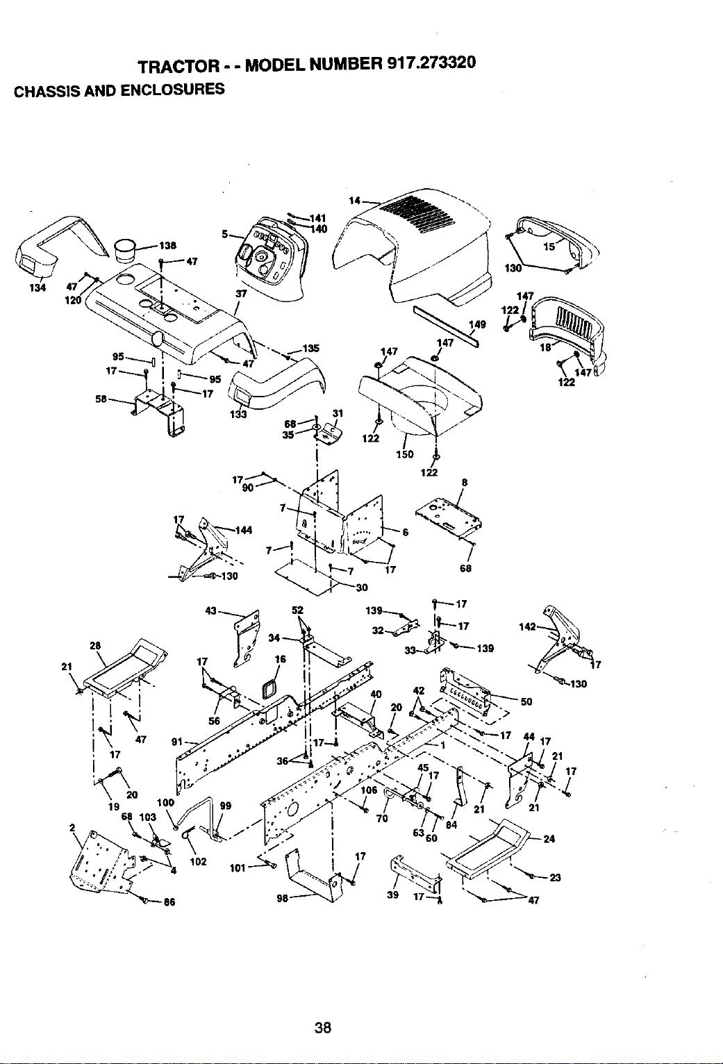
TRACTOR - - MODEL NUMBER 917.273320
CHASSIS AND ENCLOSURES
134
47
28
21
2
I
I 47
17
19
17
56
100
102 101_
86
15o
122
8
/
17 68
42
7O
_17 44 17
17
39
38
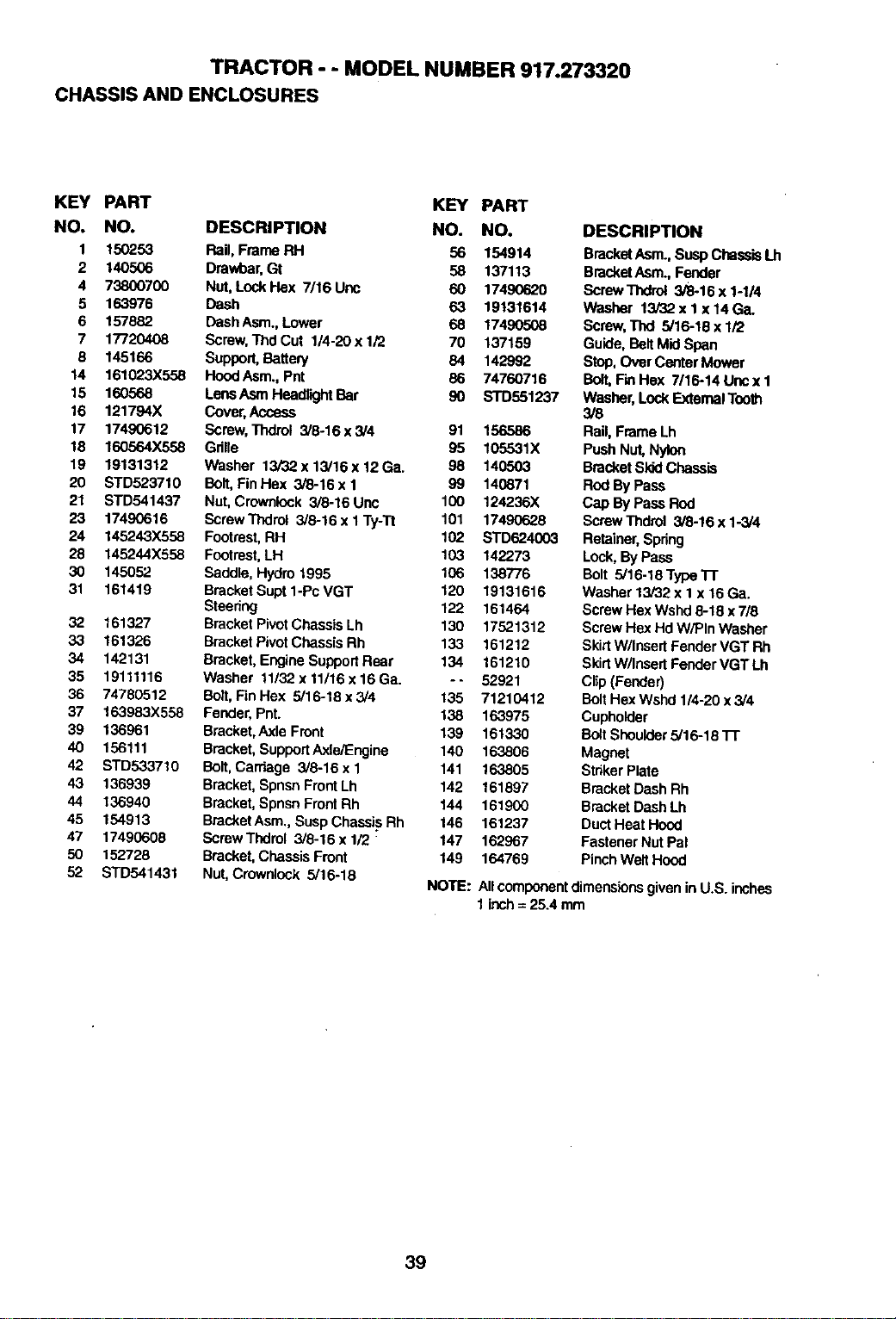
TRACTOR - - MODEL NUMBER 917.273320
CHASSIS AND ENCLOSURES
KEY PART KEY PART
NO. NO. DESCRIPTION NO. NO.
1 150253 Rail, Frame RH 56 154914
2 140506 Drawbar,Gt 58 137113
4 73800700 Nut, LockFlex 7116Unc 60 17490620
5 163976 Dash 63 19131614
6 157882 DashAsm., Lower 68 17490508
7 17720408 Screw,ThdCut 1/4-20 x 1/2 70 137159
8 145166 Support,_tte_ 84 142992
14 161023)(558 HoodAsm., Pnt 86 74760716
15 160568 LensAsm HeadlltjhtBar 90 STD551237
16 121794X Cover,Access
17 17490612 Screw,Thdrol 3/8-16x3/4 91 156586
18 160564X558 Gdlle 95 105531X
19 19131312 Washer 13/32x 13/16x 12Ga. 98 140503
20 STD523710 Bolt,Fin Hax 3/8-16 x I 99 140871
21 STD541437 Nut,Crownlock 3/8-16 Uric 100 124236X
23 17490616 ScrewThdrol 3/8-16 x I Ty-Tt 101 17490628
24 145243)(558 Footrest,RH 102 STD624003
28 145244X558 Footrest,LH 103 142273
30 145052 Saddle, Hydro 1995 106 138776
31 161419 BrackatSuptl-PcVGT 120 19131616
Steering 122 161464
32 161327 Bracket PivotChassisLh 130 17521312
33 161326 BracketPivotChassisRh 133 161212
34 142131 Bracket, EngineSupportRear 134 161210
35 19111116 Washer 11/32x11/16x16Ga. -- 52921
36 74780512 Bo/t, FinHax 5/16-18x3/4 135 71210412
37 163983X558 Fender, Pnt. 138 163975
39 136961 Bracket,Axle Front 139 161330
40 156111 Bracket, SupportAxle/Engine 140 163806
42 STD533710 Bott,Carhage 3/8-16 x 1 141 163805
43 136939 Bracket, SpnsnFront Lh 142 161897
44 136940 Bracket, SpnsnFront Rh 144 161900
45 154913 BracketAsm., SuspChass'L§Rh 146 161237
47 17490608 Screw Tndrol 3/8-16 x 1/2 • 147 162967
50 152728 Bracket,ChassisFront 149 164769
52 STD541431 Nut,Crownlock 3/16-18
DESCRIPTION
BracketAsm.,SuspChass'BLh
BracketAsm.,Fender
Screw'/_drol 3/8-16 x1-1/4
Washer 13/32x 1 x 14Ga.
Screw,Thd 5/16-18 x 1/2
Guide, Bait Mid Span
Stop, OverCenter Mower
Bolt,FinHex 7/16-14 Uricx 1
Washer, Lock ExternalTooth
3/8
Rail, Frame Lh
Push Nut,Nylon
BracketSkidChassis
Rod By Pass
Cap By PassROd
ScrewThdrol 3/6-16 x 1-3/4
Reta'lner,Spring
Lock,ByPass
Bolt 5/16-18 Type1-1"
Washer 13/32 x I x 16Ga.
ScrewHex Wshd8-18 x 7/8
ScrewHex HdW/PIn Washer
SkirtW/Insert FenderVGT Rh
SkirtW/Insert FenderVGT Lh
Clip(Fender)
Bolt Hex Wsnd 1/4-20 x 3/4
Cupholder
Bo_tShoulder5/16-18 "11"
Magnet
Str_kerPrate
Bracket DashRh
Bracket DashLh
DuctHeat Hood
Fastener NutPal
PinchWelt Hood
NOTE: AllcomponentdimensionsgiveninU.S. inches
1inch= 25.4 mm
39
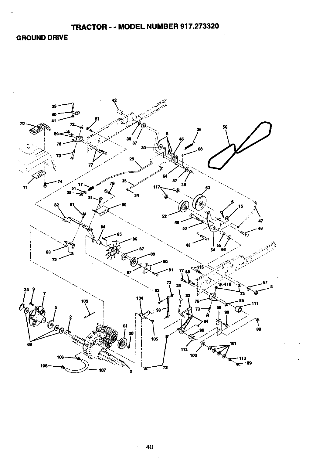
TRACTOR - - MODEL NUMBER 917.273320
GROUND DRIVE
33 9
2
37
38
117_
72
104
112
100
2
4O
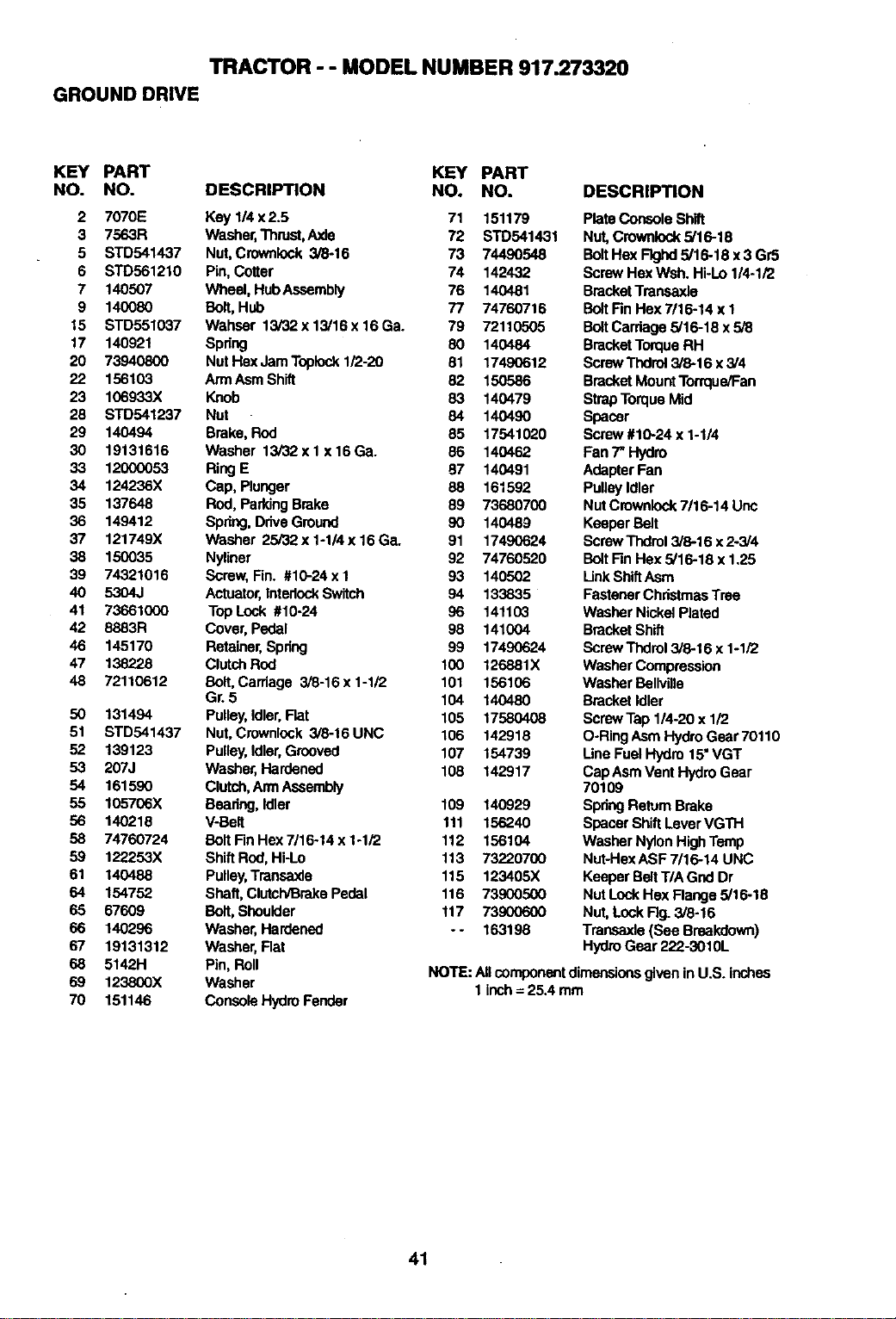
TRACTOR - - MODEL NUMBER 917.273320
GROUND DRIVE
KEY PART KEY PART
NO. NO. DESCRIPTION NO. NO.
2 7070E Key 1/4x2.5 71 151179
3 7563R Washer,Thrust,Axle 72 STD541431
5 STD541437 Nut,Crownleck 3/8-16 73 74490548
6 STD561210 Pin,Cotter 74 142432
7 140507 Wheel, HubAssembly 76 140481
9 140080 Bolt, Hub 77 74760718
15 STD551037 Wahser 13/32x13/16x16Ga. 79 72110505
17 140921 Spdng 80 140484
20 73940800 Nut Hex JamToplock1/2-20 81 17490612
22 156103 ArmAsmShift 82 150586
23 106933X Knob 83 140479
28 STD541237 Nut 84 140490
29 140494 Brake, Rod 85 17541020
30 19131616 Washer 13/32xl x16Ga. 86 140462
33 12000053 RingE 87 140491
34 124236X Cap, Plunger 88 161592
35 137648 Rod, ParkingBrake 89 73680700
36 149412 Spring,Drive Ground 90 140489
37 121749X Washer 25/32 x 1-1/4 x 16 Ga. 91 17490624
38 150035 Nyliner 92 74760520
39 74321016 Screw, Fin. #10-24 xI 93 140502
40 5304J Actuator,InterlockSwitch 94 133835
41 73661000 TopLock #10-24 96 141103
42 8883R Cover, Pedal 98 141004
46 145170 Retainer,Spdng 99 17490624
47 138228 ClutchROd 100 126881X
48 72110612 Bolt,Carriage 3/8-16x 1-1/2 101 156106
Gr. 5 104 140480
50 131494 Pulley,idler,Flat 105 17580408
51 STD541437 Nut,Crownlock 3/8-16 UNC 106 142918
52 139123 Pulley,Idler,Grooved 107 154739
53 207J Washer, Hardened 108 142917
54 161590 Clutch,ArmAssembly
55 105706X Beedng, Idler 109 140929
56 140218 V-Belt 111 156240
58 74760724 Bolt Fin Hex 7/16-14 x 1-1/2 112 156104
59 122253X Shift ROd,Hi-Lo 113 73220700
61 140488 Pulley,Traneaxle 115 123405X
64 154752 Shaft, Clutch_rake Pedal 116 73900500
65 67609 Bolt, Shoulder 117 73900600
66 140296 Washer, Hardened - - 163198
67 19131312 Washer, Flat
68 5142H Pin, Boll
69 123800X Washer
70 151146 Console HydroFender
DESCRIPTION
Plate ConsoleShift
Nut,Crownlock5/16-18
BoltHex Fk3hd5/16-18 x3 Gr5
ScrewHex Wsh. Hi-Lo 1/4-1/2
BracketTransaxle
BoltFinHex 7116-14x 1
BoltCarriage 5/16-18 x 5/8
BracketTorqueRH
ScrewThdrol3/6-16 x5/4
BracketMountTorrque/Fan
StrapTorque Mid
Spacer
Sci'ew#10-24 x 1-1/4
Fan 7" Hydro
AdapterFan
PulleyIdler
Nut Crownlock7/16-14 Unc
Keeper Belt
ScrewThdrol3/8-16 x2-3/4
BoltFinHex 5/16-18 x 1,25
LinkShiftAsm
Fastener ChristmasTree
Washer NickelPlated
BracketShift
Screw Thdrol3/6-16 x 1-1/2
WasherCompression
Washer Bellvilla
BracketIdler
Screw Tap1/4-20 x 112
O-RingAsm HydroGear 70110
LineFuel Hydro 15"VGT
Cap AsmVent HydroGear
70109
SpdngReturnBrake
SpacerShiftLever VGTH
Washer Nylon HighTemp
Nut-HexASF 7/16-14 UNC
Keeper BeltT/A Gnd Dr
Nut LockHe)(Flange5/16-18
Nut,LockFig. 3/8-16
Transaxle (See Breakdown)
HydroGear 222-3010L
NOTE: All componentdimensionsgiven in U.S. inches
1 inch= 25.4 mm
41
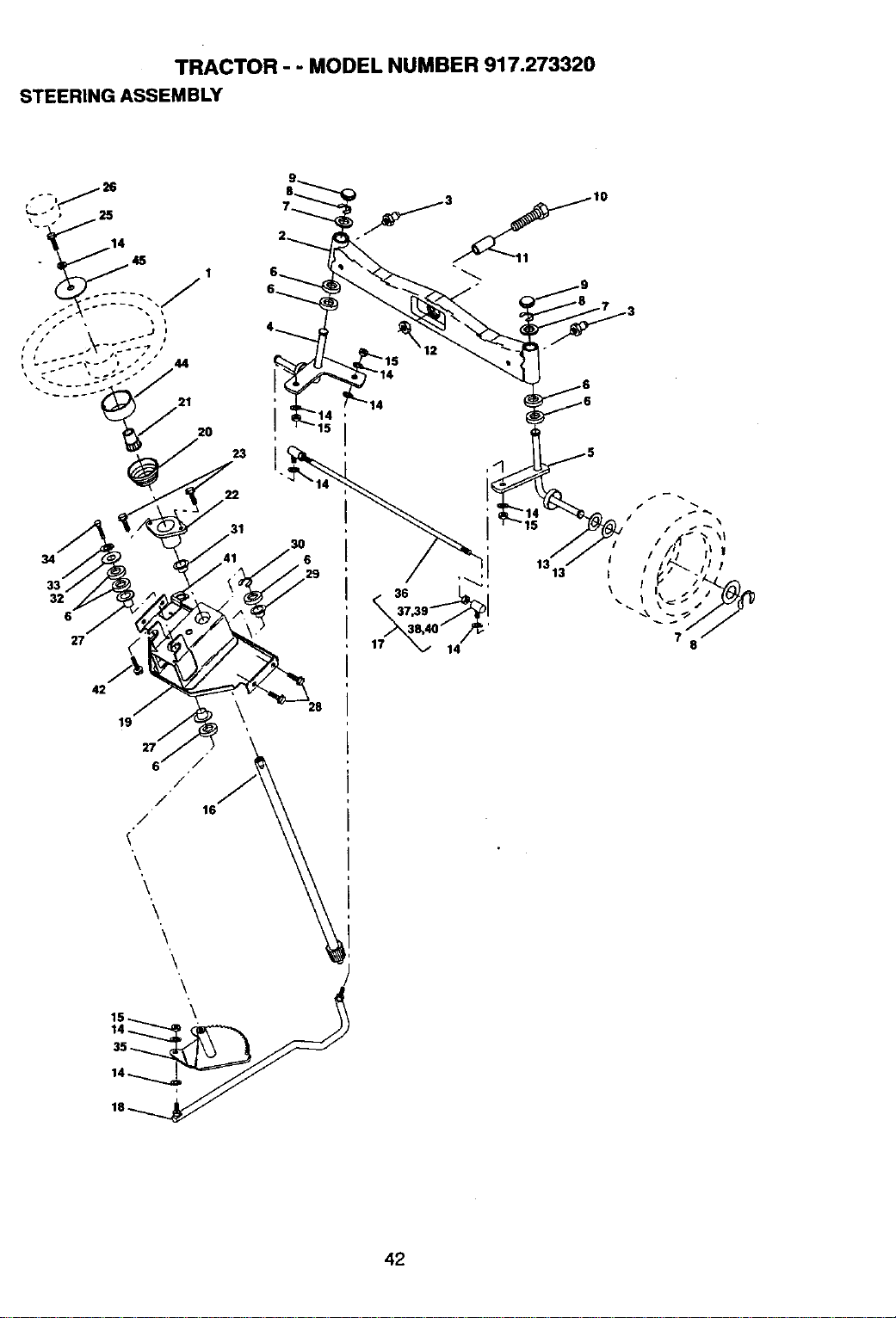
TRACTOR - - MODEL NUMBER 917.273320
STEERING ASSEMBLY
1
23
31
34
32
6
27
<"
42
19 \ 28
g /
/-
/
/ 16
'\
\
\
\
\
\
7
8
42
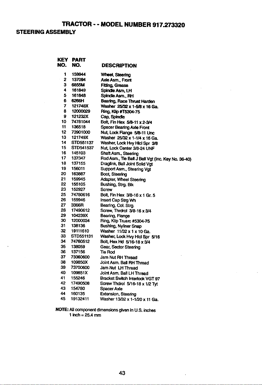
TRACTOR - - MODEL NUMBER 917.273320
STEERINGASSEMBLY
KEY PART
NO. NO. DESCRIPTION
1 158944
2 137O94
3 6855M
4 161849
5 161848
6 6266H
7 121748X
8 12000029
9 121232X
10 74781044
11 136518
12 73901000
13 121749X
14 STD551137
15 STD541537
16 145103
17 137347
18 137155
19 156011
20 163887
21 159945
22 155105
23 152927
25 74780616
26 159945
27 3366R
28 17490612
29 104239X
3O 1200OO34
31 138136
32 19111610
33 STD551131
34 74760512
35 138059
36 137156
37 733_0600
38 109850X
39 73700600
40 109851X
41 155246
42 17490508
43 154780
44 160135
45 19132411
Wheel, Steering
A._deAsm., Front
Fitting,Grease
SpindlaAsm, LH
Splr_e Asm., RH
Baadng, Race ThrustHarden
Washer 23/'3_x 1-3/8 x 16 Ga.
Ring,K]lp#T5304-75
Cap, Spind_
Bolt,F_ Hex 5/8-11 x2-3/4
SpacerBeadngAxle Front
Nut,LockFlange 5/8-11Unc
Washer 25132x 1-1/4 x 16Ga.
Washer,Loci<I-IvyHlclSpr 3/8
Nut, LockCenter 3/8-24 UNF
ShaftAsm.,Steering
RodAsm.,Tie BallJ Ball Vgt (Inc. KeyNo. 36-40)
Draglink,Ball JointSolidVgt
SupportAsm.,SteeringVgt
Boot,Steering
Adapter,Wheel Steering
Bushing,Strg.BIk
Screw
Bolt,FinHex 3/8-16 x 1 Gr.5
InsertCap StrgWh
Baadng, Col.Strg.
Screw,Thrdrol 3/8-16 x3/4
Bearing,Flange
Ring,KlipTruarc#5304-75
Bushing,NylinerSnap
Washer 11/32x I x 10Ga.
Washer,Lock Hvy HlclSpr 5/16
Boit,Hex Hd 5/16-18 x 3/4
Gear, SectorSteering
Tie Rod
Jam Nut RH'Thread
JointAsm. Ball RH Thread
Jam Nut LHThread
JointAsm.BallI_HThread
BracketSwitchInterlockVGT 97
ScrewThdrol 5/16-18 x 1/2 Tyt
SpacerAxle
Extension,Steenng
Washer 13/32 x 1ol/20x 11 Ga.
NOTE: All componentdimensionsgivenin U.S. inches
1 Inch= 25.4 mm
43
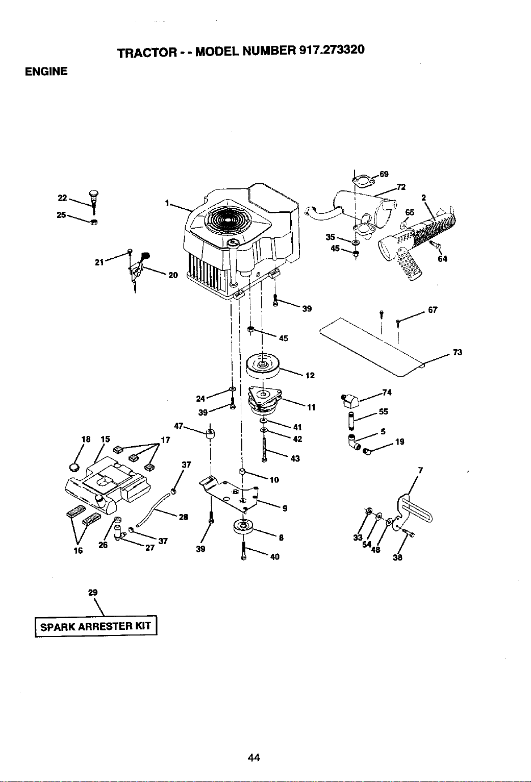
ENGINE
TRACTOR - - MODEL NUMBER 917.273320
18 15
2
i
64
73
_j74
js
7
16 26 27 39
38
29
\
[SPARK ARRESTER KIT I
44
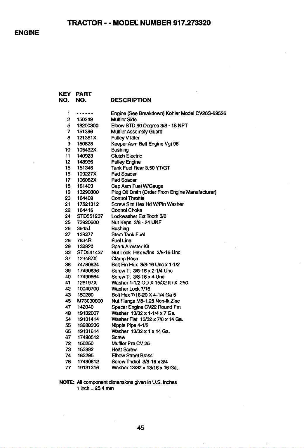
ENGINE
TRACTOR - - MODEL NUMBER 917.273320
KEY PART
NO. NO. DESCRIPTION
1
2 150249
5 13200300
7 151396
8 121361X
9 150828
10 105432)(
11 140923
12 143996
15 151346
16 109227X
17 lO6O82X
18 161493
19 13290300
20 164409
21 17521312
22 164416
24 STD551237
25 73920600
26 3645J
27 139277
28 7834R
29 132920
33 STD541437
37 123487X
38 74780624
39 17490636
40 1749(3664
41 126197X
42 10040700
43 150280
45 M73030800
47 142040
48 19132007
54 19131414
55 13280336
65 19131614
67 17490512
72 150250
73 153992
74 162295
76 17490612
77 19131316
NOTE:
Engine(See Breakdown)KohlerModel CV26S-69526
MufflerSide
ElbowSTD 90 Degree 3/8 - 18 NPT
MufflerAssemblyGuard
PulleyV-Idler
Keeper Asm BeltEngineVgt 86
Bushing
Clutch Electric
PulleyEngine
Tank Fuel Rear 3.50 YT/GT
Pad Spacer
Pad Spacer
Cap AsmFuelW/Gauge
Plug Oil Drain(Order From EngineManufacturer)
ControlThmtlte
ScrewSitd HexHd W/PIn Washer
ControlChoke
LockwssherExtTooth3/8
Nut Keps 3/8 - 24 UNF
Bushing
StemTankFuel
FuelLine
SparkAn'esterWJt
Nut Lock Hex w/Ins 3/8-16 Une
ClampHose
BoltRn Hex 3/8-16 Uricx 1-1/2
ScrewTt 3/8-16 x 2-1/4 Unc
Screw Tt 3/8-16 x4 Unc
Washer 1.1/20D X 15/32 ID X .250
Washer Lock7/16
Bolt Hex 7/16-20 X 4-1/4 Ga 5
Nut FlangeM6-1.25 Non-lkZinc
Spacer EngineCV22 RoundPm
Washer 13/32 x 1-1/4 x 7 Ga,
Washer Flat 13/32 x 7/8 x14 Ga.
NipplePipe4-1/2
Washer 13/32 x I x 14 Ga.
Screw
MufflerPm CV 25
Heat Screw
ElbowStreetBrass
Screw Thdrol 3/8-16 x 3/4
Washer 13/32 x 13/16 x 16 Ga.
All oomponentdimensionsgivenin U.S. inches
1 ineh= 25.4 mm
45
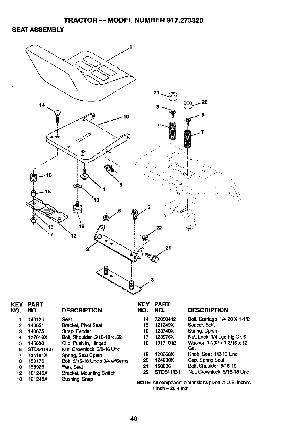
TRACTOR - - MODEL NUMBER 917.273320
SEAT ASSEMBLY
21
KEY PART
NO. NO.
1 140124
2 140551
3 140675
4 127018X
5 145006
6 STD541437
7 124181X
8 150176
10 155925
12 121246X
13 121248X
DESCRIPTION
Seat
Bracket,PivotSeat
Strap,Fender
Bolt,Shoulder 5/16-18 x .62
Clip, PushIn, Hinged
Nut,Crownlock 3/8-16 Unc
Spring,SeatCprsn
Bolt 5/16-18 Uricx 3/4 w/Sems
Pan, Seat
Bracket,MountingSwitch
Bushing,Snap
KEY
NO.
PART
NO. DESCRIPTION
14 72050412 Bolt, Carriage 1/4-20X 1-1/2
15 121249X Spacer,Split
16 123740X Spring,Cprsn
17 123976X Nut,Lock 1/4Lge FigGr. 5
18 19171912 Washer 17/32x 1-3/16x 12
Ga.
19 12(X)68X Knob,Seat 1/2-13 Unc
20 124238X Cap, Spdng Seat
21 153236 Bolt, Shoulder 5/16-18
22 STD541431 Nut, Crownlock 5/16-18 Uric
NOTE: Allcomponentdimensionsgivenin U.S. inches
1inch= 25.4 mm
46
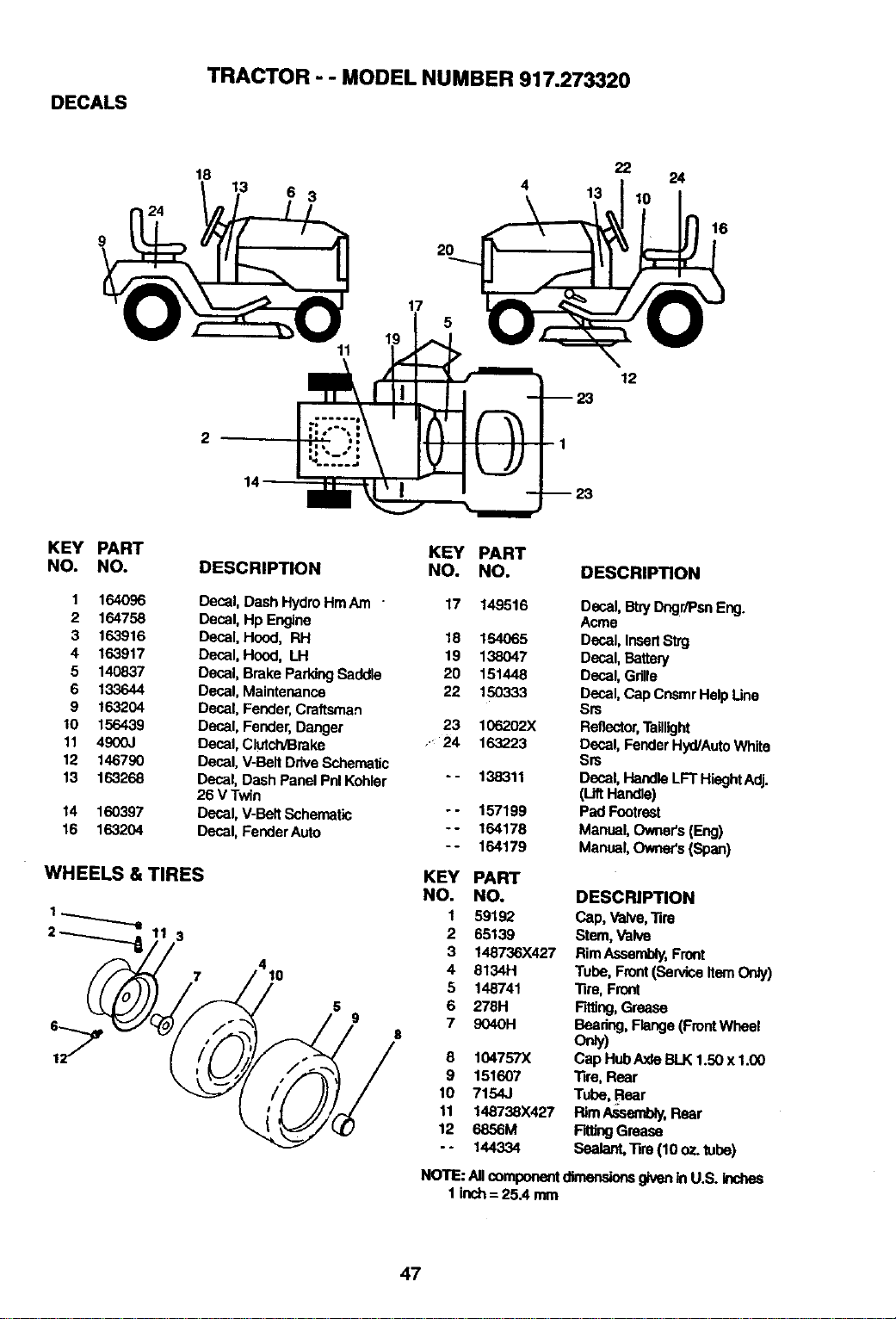
DECALS
TRACTOR - - MODEL NUMBER 917.273320
9
22
4 13
18 13 6 3
2O
24
16
19
11
5
w2O
1
12
KEY PART
NO. NO.
1 164o96
2 164758
3 163916
4 163917
5 140837
6 133644
9 163204
10 156439
11 4900J
12 146790
13 163268
14 160397
16 163204
KEY PART
DESCRIPTION NO. NO.
Decal, Dash Hydro HmAm " 17 149516
Decal, Hp Engine
Decal, Hood, P,H 18 154065
Decal, Hood, LH 19 138047
Decal, Brake ParkingSaddle 20 151448
Decal. Maintenance 22 150333
Decal, Fender,Craftsman
Decal, Fender,Danger 23 106202X
Decal,Clutch/Broke .." 24 163223
Decal,V-Belt DriveSchematic
Decal, Dash Panel PnlKohler - - 138311
26 V Twin
Decal,V-Belt Schematic - - 157199
Decal, FenderAuto -- 164178
-- 164179
WHEELS & TIRES
3
4
10
5
9
DESCRIPTION
Decal. Bby Dngr/PsnEng.
Acme
Decal, InsertStrg
Decal, Battery
Decal, Gdlle
Deca_,C_p CP_mrHelp L_no
Srs
Reflector,Taillight
Decal,FenderHyd/AutoWhite
Srs
Decal,HandleLFT HieghtAdj.
(L_tHanCe)
Pad Footrest
Manual,Owner's(Eng)
Manual,Owner's(Span)
KEY PART
NO. NO. DESCRIPTION
1 59192 Cap, Valve,_re
2 65139 Stem, Valve
3 148736X427 RimAesembly, Front
4 6134H Tube, Front(Serviceitem Ordy)
5 148741 _re, Front
6 278H Fitting,Grease
7 9040H Bearing, Range (FrontWheel
onty)
8 104757X Cap HubAxleBLK1.50 x 1.00
9 151607 _re, Rear
10 7154J Tube, Pear
11 148738X427 RimAssembly,Rear
12 6856M Fitl_ Gemse
-* 144334 Sealant.Tim (10 oz. tube)
NOTE:AncomponentdimensionsgivenInU.S.inchea
1 inch=25.4mm
47
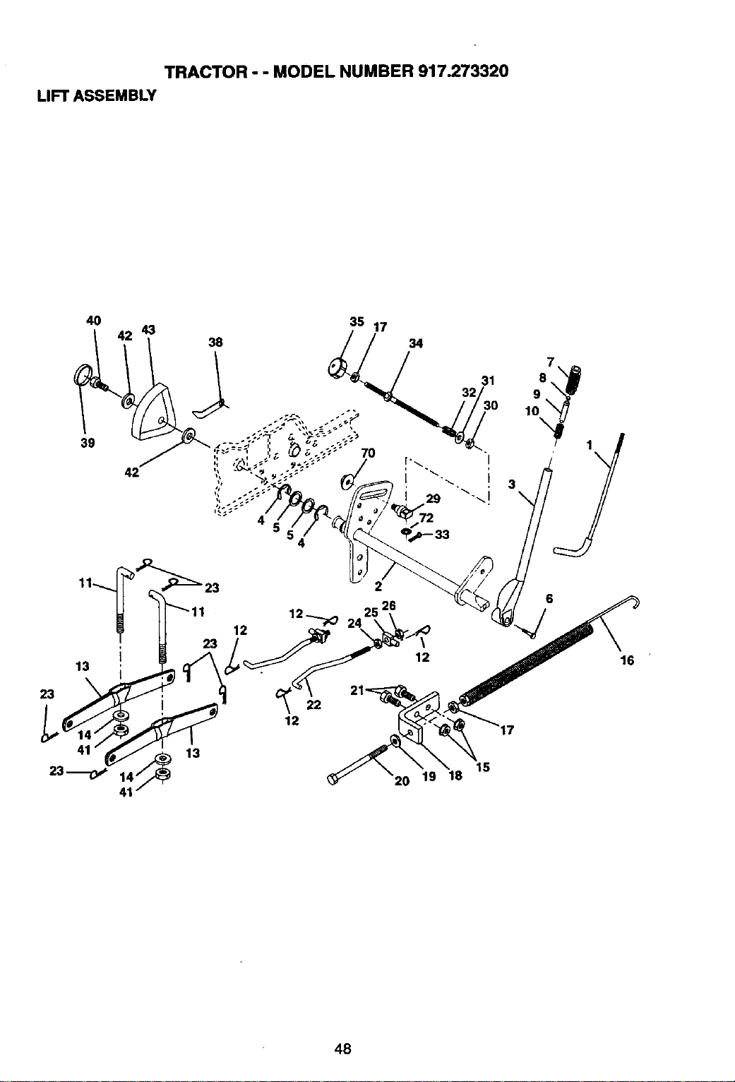
TRACTOR - - MODEL NUMBER 917.273320
LIFT ASSEMBLY
4O
39
43
38
13 I
23
15
6
16
48
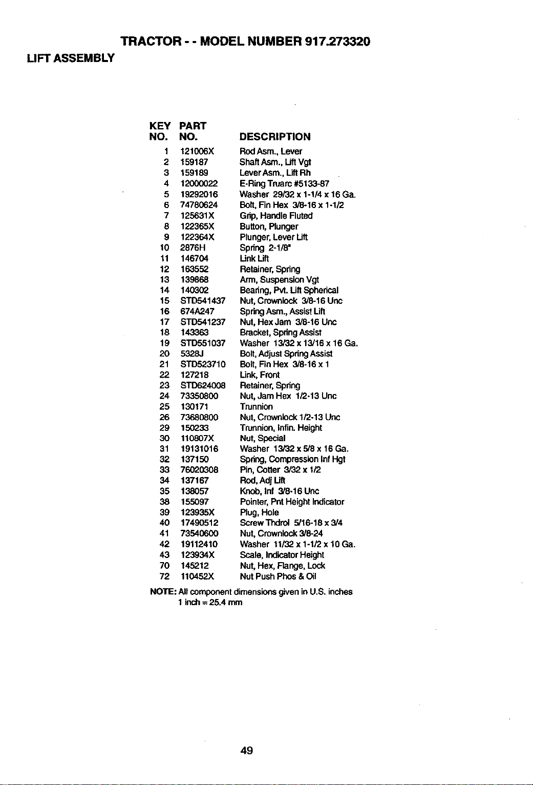
TRACTOR - - MODEL NUMBER 917.273320
LIFT ASSEMBLY
KEY PART
NO. NO. DESCRIPTION
1 121006X RodAsm.,Lever
2 159187 ShaftAsm., LiftVgt
3 159189 LeverAsm., LiftRh
4 12000022 E.Ring Truarc#5133-87
5 19292016 Washer 29/32 x 1-1/4 x 16Ga.
6 74780624 Bolt,Fin Hex 3/8ol6 x 1-1/2
7 125631X Grip,Handle Fluted
8 122365X Button,Plunger
9 122364X Plunger,Lever Lift
10 2876H Spring 2-1/8"
11 146704 LinkLift
12 163552 Retainer,Spring
13 139868 Arm, SuspensionVgt
14 140302 Bearing,Pvt. Uft Spherical
15 STD541437 Nut,Crownlock 3/8-16 Uric
16 674A247 SpringAsm.,AssistLift
17 STD541237 Nut,Hex Jam 3/8-16 Unc
18 143363 Bracket,SpringAssist
19 STD551037 Washer 13/32 x 13/16 x16 Ga.
20 5328J Bolt,AdjustSpringAssist
21 STD523710 Bolt, Fin Hex 3/8-16 x 1
22 127218 Link,Front
23 STD624008 Retainer,Spring
24 73350800 Nut, Jam Hex 1/2-13 Unc
25 130171 Trunnion
26 73680800 Nut, Crownlock1/2o13Unc
29 15C233 Trunnion,Infin.Height
30 110807X Nut,Special
31 19131016 Washer 13/32 x5/8 x 16Ga.
32 137150 Spnng,CompressionInfHgt
33 76020308 Pin,Cotter 3Y32x 1/2
34 137167 Rod,Adj Lift
35 138057 Knob,Inf 3/8-16 Unc
38 155097 Pointer,PntHeightIndicator
39 123935X Plug,Hole
40 17490512 ScrewThdrol 5/16-18x3/4
41 73540600 Nut, Crownlock3/8-24
42 19112410 Washer 11/32x 1-1/2 x 10 Ga.
43 123934X Scala, IndicatorHeight
70 145212 Nut, Hex, Flange, Lock
72 110452X Nut PushPhos&Oil
NOTE: Allcomponentdimensionsgivenin U.S. inches
1 inch=25.4 mm
49
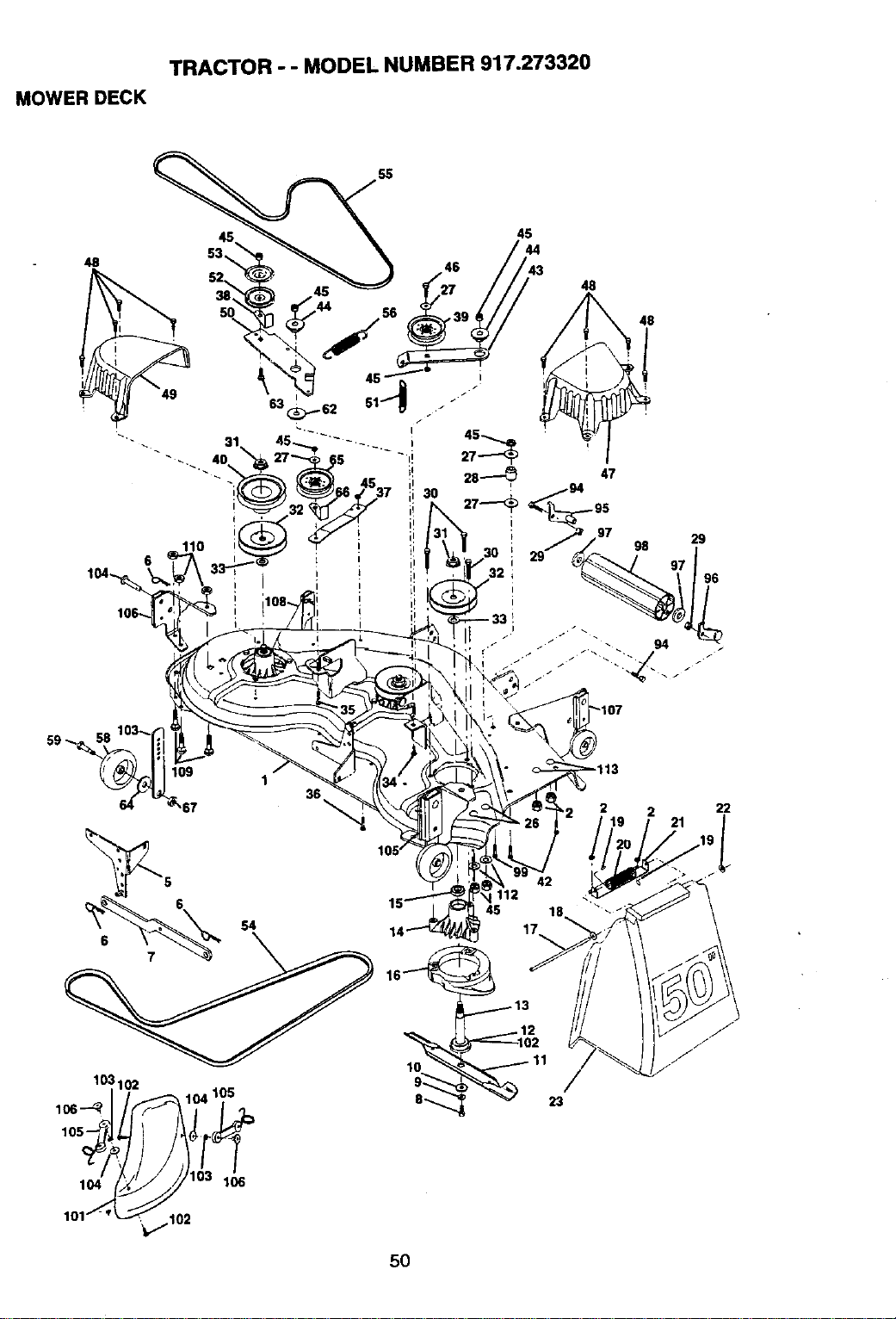
TRACTOR -- MODEL NUMBER 917.273320
MOWER DECK
55
48
6
45
48
47
48
98
29
67
1
36
21
22
S4
103102
104105
10
l_j 103 1"
101_-'_102
5O
112
45
17_,
j13
1123
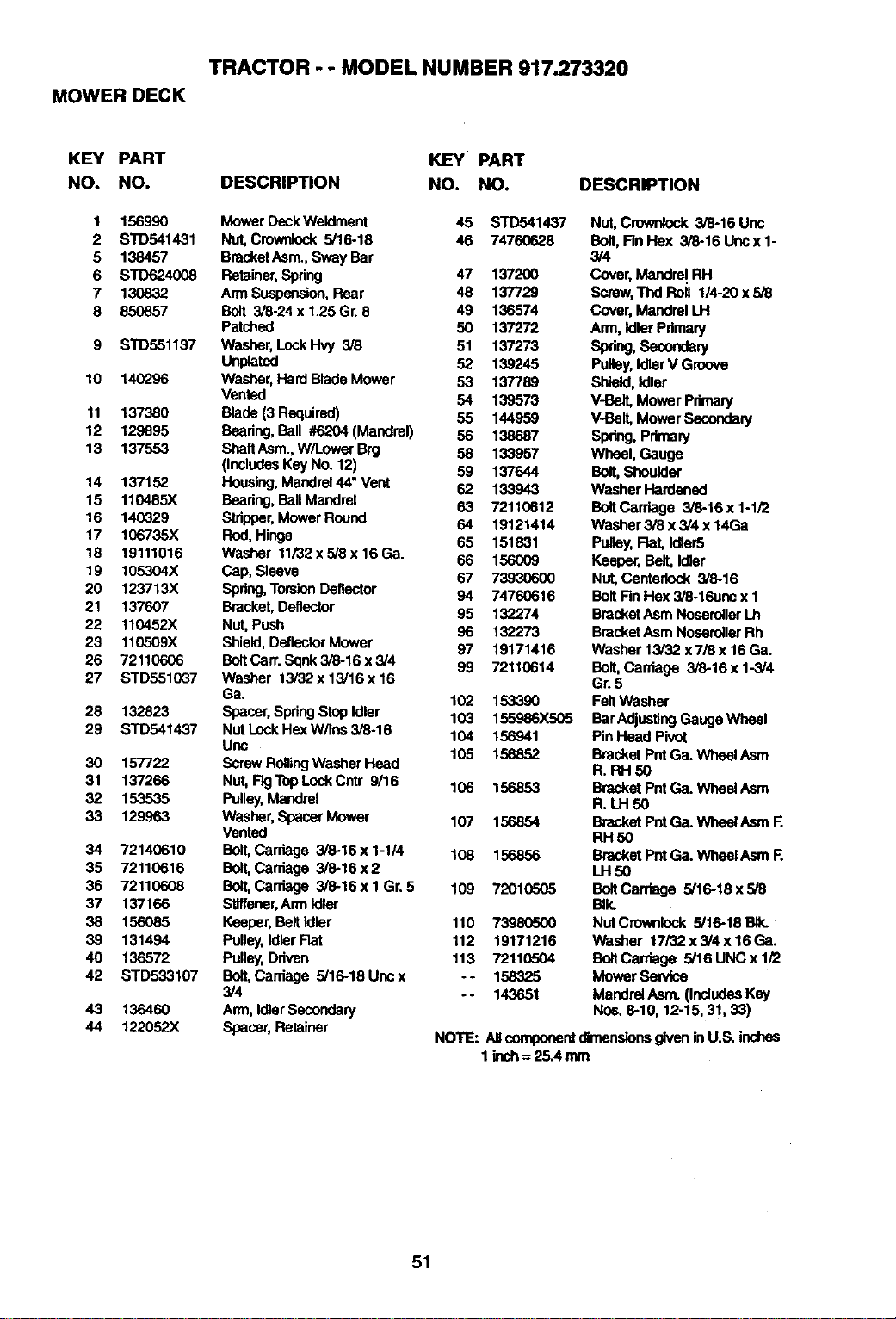
TRACTOR - - MODEL NUMBER 917.273320
MOWER DECK
KEY PART KEY PART
NO. NO. DESCRIPTION NO. NO,
1
2
5
6
7
8
10
11
12
13
14
15
16
17
18
19
20
21
22
23
26
27
28
29
3O
31
32
33
34
35
36
37
38
39
4o
42
43
44
156990 Mower DeckWeldment 45 STD541437
STD541431 Nut,Cmwnlock 5/16-18 46 74760628
138457 BracketAsm.,Sway Bar
STD624008 Retainer,Spring 47 137200
130832 Arm Suspension,Rear 48 137729
850857 Bolt 3/8-24x1.25Gr. 8 49 136574
Patched 50 137272
STD551137 Washer, LockHvy 3/8 51 137273
Unplated 52 139245
140296 Washer, Hard Blade Mower 53 137789
Vented 54 139573
137380 Blade(3 Required) 55 144959
129895 Beedng,Ball #6204 (Maedrel) 56 138687
137553 ShaftAsm.,W/Lower B_I 58 133957
(IncludesKey No. 12) 59 137644
137152 Housing,Mandrel44"Vent 62 133943
110485X Bearing,Ball Mandrel 63 72110612
140329 Stripper,Mower Round 64 19121414
106735X Red, Hinge 65 151831
19111016 Washer 11i32x5/8x16Ga. 66 156009
105304X Cap, Sleeve 67 73930600
123713X Spdng,TorsionDeflector 94 74760616
137607 Bracket,Deflector 95 132274
110452X Nut,Push 96 132273
110509X Shield, DeflectorMower 97 19171416
72110606 BoltCart. Sqnk3/8-16 x 3/4 99 72110614
STD551037 Washer 13/32 x 13/16 x 16
Ga. 102 153390
132823 Spacer,SpdngStopIdler 103 155986X505
STD541437 NutLockHexW/Ins 3/8-16 104 156941
Unc
105 156852
157722 ScrewRollingWasher Head
137266 Nut,FIgTopLockCntr 9/16 106 156853
153535 Pulley,Mandrel
129963 Washer,Spacer Mower 107 156854
Vented
72140610 Bolt,Carriage 3/8-16 x 1-1/4 108 156856
72110616 Bolt,Carriage 3/8-16 x 2
72110608 Bolt,Cardage 3/8-16xl Gr. 5 109 72010505
137166 Stiffener,Arm Idler
156085 Keeper,BeltIdler 110 73980600
131494 Pulley,IdlerHat 112 19171216
136572 Pulley,Ddven 113 72110504
STD533107 Bolt,Cardage 5/16-18 Unc x - o 158325
3/4 -- 143651
136460 Ann, IdlerSecondary
122062X Spacer,Retainer
DESCRIPTION
Nut,Crownlock 3/8-16 Unc
Bolt,Fin Hex 3/8-16 Uricx 1-
3/4
Cover,Mandrel RH
Scraw,Thd Roll 1/4-20 x5/8
Cover, MandrelLH
Arm, Idler Pdmary
Spdng,Secondary
Pulley, IdlerV Groove
Shield, Idler
V-Belt, Mower Pdmary
V-Bait, MowerSecondary
Spring,Pdmary
Wheel, Gauge
Bolt,Shoulder
Washer Hardened
BoltCardage 3/8-16 x 1-1/2
Washer 3/8 x 3/4x 14Ga
Pulley,Hat, Idler5
Keeper, Belt,Idler
Nut,Centerlock 3/8-16
BoltRn Hex 3/8-16unc x 1
BracketAsm NoseroflerLh
BracketAsm NoserollerRh
Washer 13/32 x7/8 x16 Ga.
Bolt,Carriage 3/8-16 x 1-3/4
Gr.5
Felt Washer
Bar AdjustingGauge Wheel
PinHead Pivot
Bracket PntGa. WheelAsm
R. RH 50
Bracket PUtGa. WheelAsrn
R. LH 50
Bracket Pnt Ga. Wheel AsrnR
RH 50
Bracket PntGa. WheetAsm R
LH50
BoltCarriage 5/16-18 x 5/8
B_k.
NUtCmwnkP.._ 5/16-18 _
Washer 17/32 x 3/4 x 16 Ga.
BoltCarriage 5/16 UNC x 1/2
Mower Sendce
Mandrel Asm. (Indudee Key
Nos. 8-10, 12-15, 31, 33)
NOTE: Aflcomponentdlmensionegiven inU.S. inches
1lech=25Amm
51
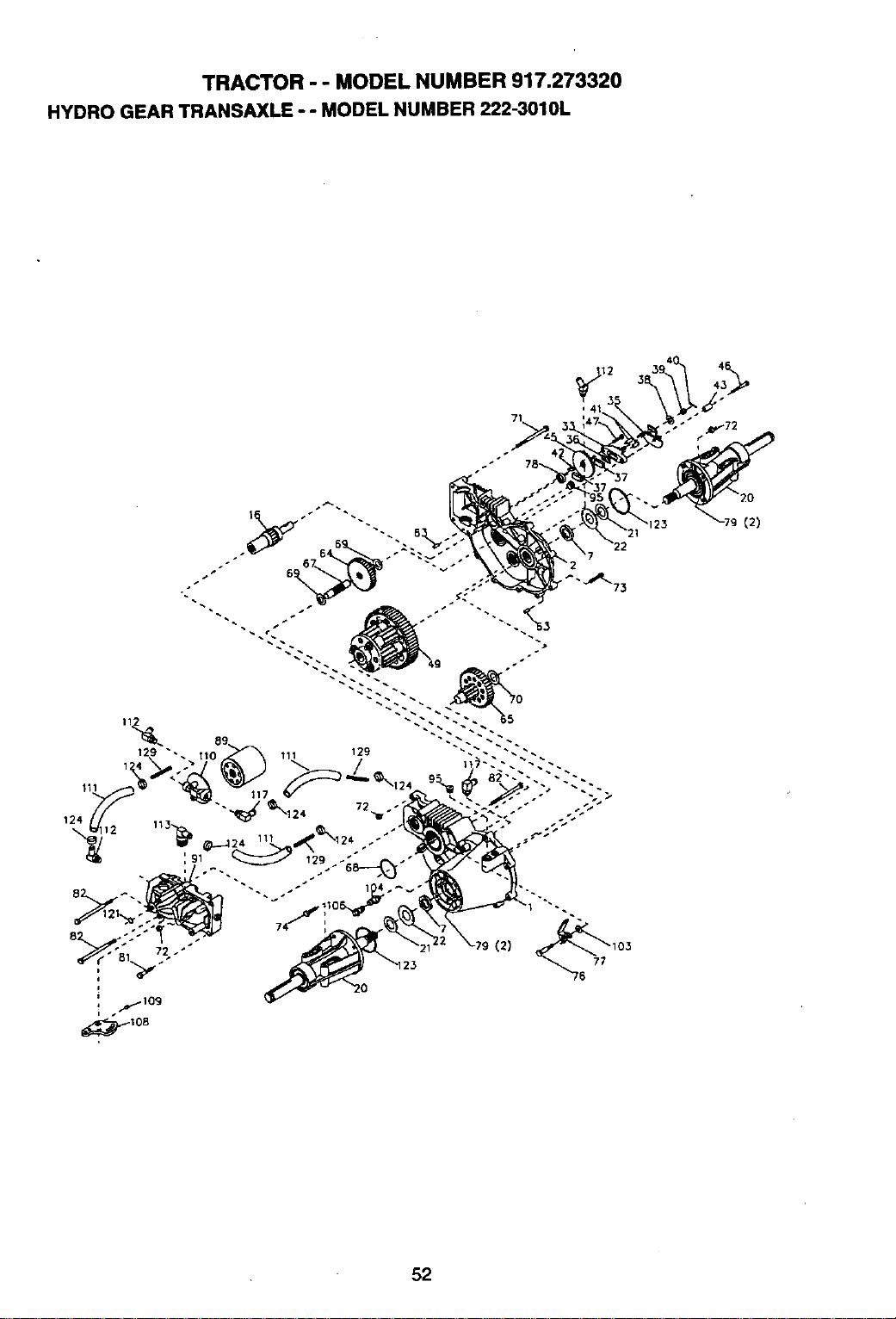
TRACTOR - - MODEL NUMBER 917.273320
HYDRO GEAR TRANSAXLE ° - MODEL NUMBER 222-3010L
52
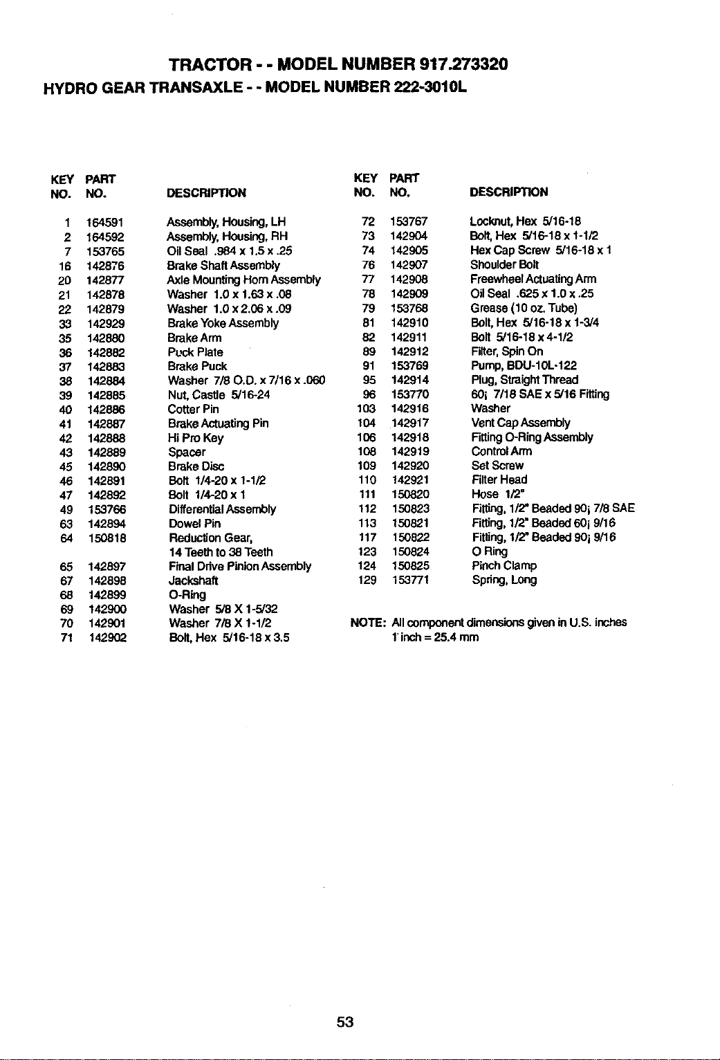
TRACTOR - - MODEL NUMBER 917.273320
HYDRO GEAR TRANSAXLE - - MODEL NUMBER 222-3010L
KEY PART KEY PART
NO. NO. DESCRIPTION NO. NO. DESCRIPTION
1 164591 Assembly,Housing,LH 72 153767
2 164592 Assembly,Housing,RH 73 142904
7 153765 Oil Seal .984 x 1.5 x .25 74 142905
16 142876 Brake ShaftAssembly 76 142907
20 142877 Axle MountingHornAssembly 77 142908
21 142878 Washer 1.0 x 1.63 x .08 78 142909
22 142879 Washer 1.0 x2.06 x .09 79 153768
33 142929 Brake YokeAssembly 81 142910
35 142880 BrakeArm 82 142911
36 142882 Puck Plate 89 142912
37 142883 Brake Puck 91 153769
38 142884 Washer 7/80.D. x 7/16 x .060 95 142914
39 142885 Nut, Castle 5/16-24 96 153770
40 142886 CofterPin 103 142916
41 142887 BrakeActuatingPin 104 142917
42 142888 Hi Pro Key 106 142918
43 142889 Spacer 108 142919
45 142890 Brake Disc 109 142920
46 142891 Bolt 1/4-20 x 1-1Y2 110 142921
47 142892 Bolt 1/4-20xl 111 150820
49 153766 DifferantialAssembly 112 150823
63 142894 Dowel Pin 113 150821
64 150818 ReductionGear, 117 150822
14 Teethto 38 Teeth 123 150824
65 142897 Final DrivePintonAssembly 124 150825
67 142898 Jackshaft 129 153771
68 142899 O-Ring
69 142900 Washer 5/8 X 1-5/32
70 142901 Washer 7/8 X 1-1/2
71 1429(_ Bolt, Hex 5/16-18x3.5
Locknut,Hex 5/16o18
Bolt, Hex 5/16-18 x t-1/2
HexCap Screw 5/16-18 x 1
ShoulderBolt
FreewheelActuatingArm
Otl Seal .625 x 1.0 x.25
Grease (10 oz.Tube)
Bolt, Hex 5/16-18 x 1-3/4
Bolt 5/16-18 x 4-1/2
Filter,Spin On
Pump,BDU-10L-122
Plug,StraightThread
601 7/18 SAE x 5/16 Fitting
Washer
Vent Cap Assembly
FittingO-RingAssembly
ControlArm
Set Screw
FilterHead
Hose 1/2"
Fitting,1/2"Beaded90i 7/8 SAE
Fitting,1/2"Beaded60i 9/16
Fitting,1/2"Beaded90i 9/16
O Ring
PinchClamp
Spdng,Long
NOTE: Allcomponentdimensieasgiven inU.S. inches
1inch= 25.4 mm
53
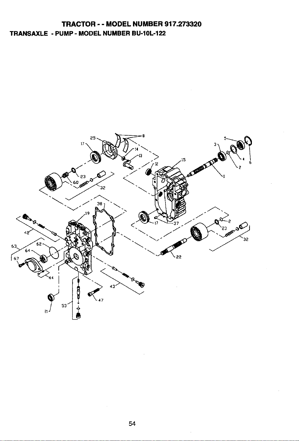
TRACTOR - - MODEL NUMBER 917.273320
TRANSAXLE - PUMP - MODEL NUMBER BU-10L-122
/
54
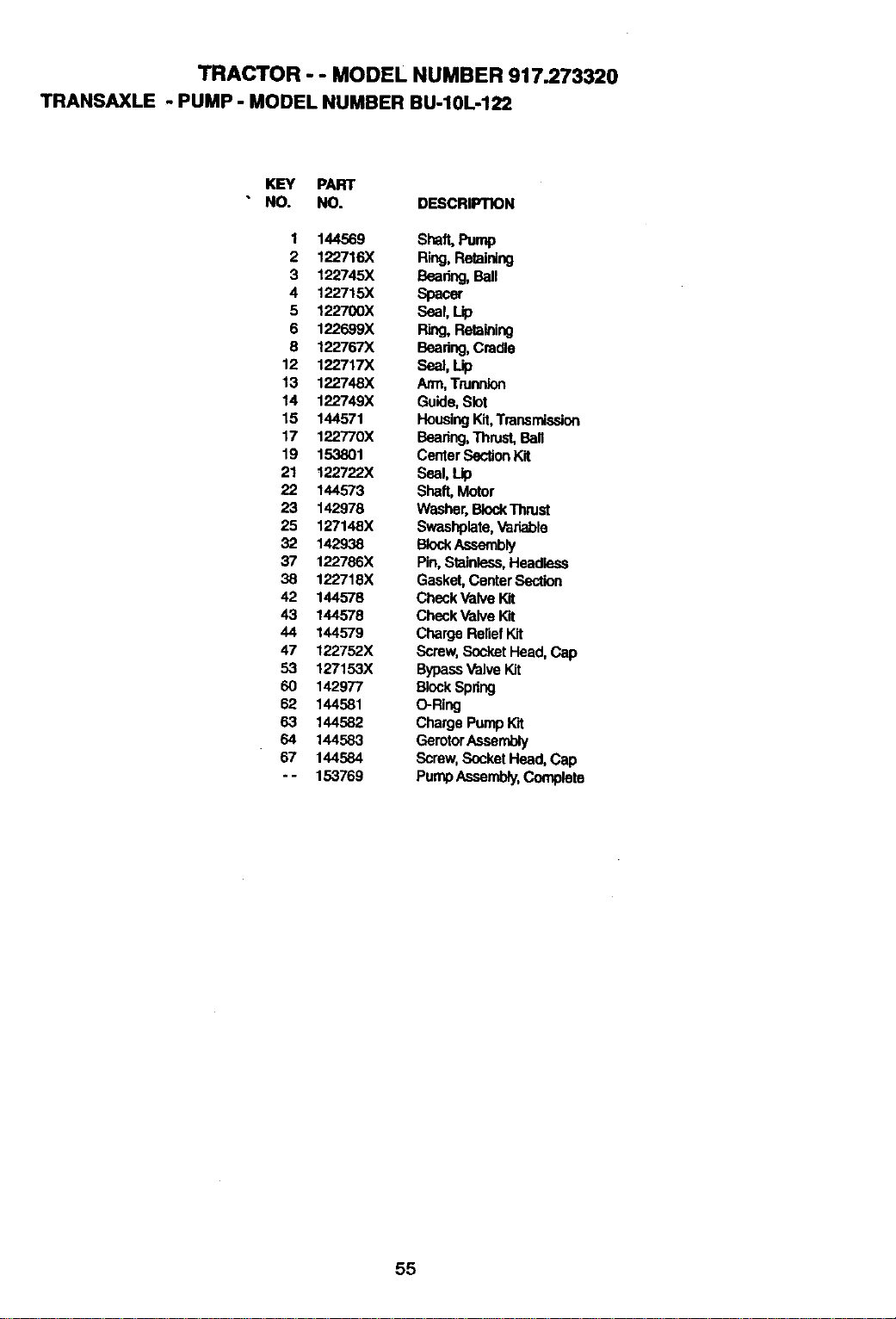
TRACTOR - - MODEL NUMBER 917.273320
TRANSAXLE - PUMP - MODEL NUMBER BU-10L-122
KEY PART
NO. NO. DESCRIPTION
1 144569 Shaft,Pump
2 122716X Ring,Retaining
3 122745X Bearing,Ball
4 122715X Spacer
5 122700X Seal,Lip
6 122699X Ring,Retaining
8 122767X Beadng,Cradle
12 122717X Seal,Lip
13 122748X Arm, Trunnion
14 122749X Guide,Slot
15 144571 HousingKit,Transmission
17 122770X Bearing,Thrust,Ball
19 153801 CenterBaction Kit
21 122722X Seal, Lip
22 144573 Shaft, Motor
23 142978 Washer,BiockThrust
25 127148X Swashplate,Variable
32 142938 BlockAssembly
37 122786X Pin,Stainless,Headless
38 122718X Gasket,CenterSection
42 144578 CheckValve Kit
43 144578 CheckValve Kit
44 144579 Charge ReliefKit
47 122752X Screw,SocketHead, Cap
53 127153X BypassValveKit
60 142977 BlockSpring
62 144581 O-Ring
63 144582 Charge Pump Wit
64 144583 GerotorAssembly
67 144584 Screw, SocketHead, Cap
- - 153769 PumpAssembly,Complete
55
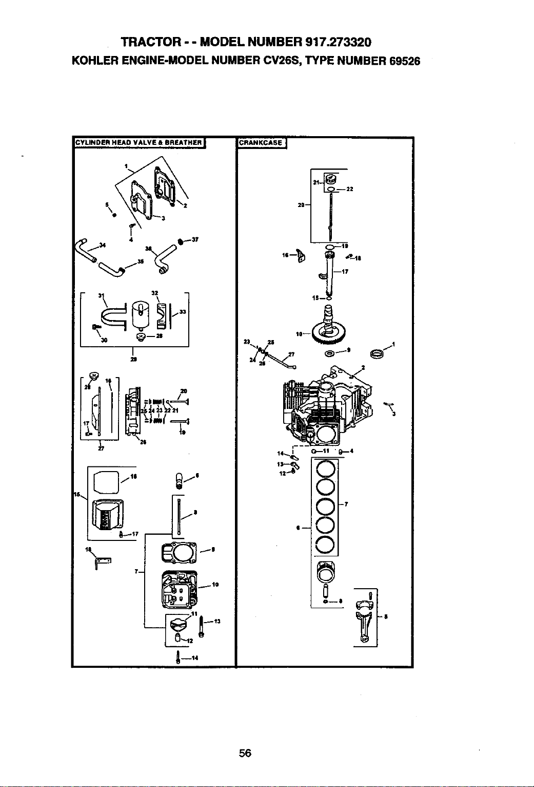
TRACTOR - - MODEL NUMBER 917.273320
KOHLER ENGINE-MODEL NUMBER CV26S, TYPE NUMBER 69526
CYLINDER HEAD VALVE & BREATHER J
I
t/
I
2S
18.,
,\
P
T--
Awl4
A
-7
A
m
a
O--8
56
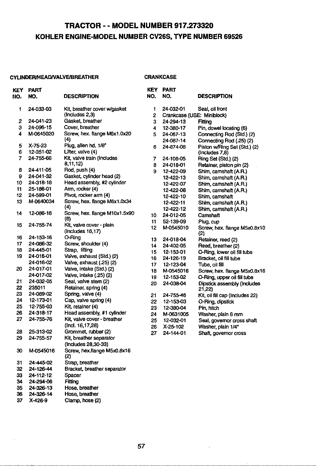
TRACTOR - - MODEL NUMBER 917.273320
KOHLER ENGINE-MODEL NUMBER CV26S, TYPE NUMBER 69526
CYLINDER/HEAD/VALVE/BREATHER
KEY PART
NO. NO.
CRANKCASE
1 24-033-03
2 24-041-23
3 24-096,15
4 M-0645020
5
6
7
8
9
10
11
12
13
14
15
16
17
18
19
20
21
22
23
24
25
26
27
28
29
3O
31
32
33
34
35
36
37
)(-75-23
12-351-02
24-755-66
24-411-05
24-041-32
24-318-18
25-186-01
24-599-01
M-0640034
12-086-16
24-755-74
24-153-16
24-O86-32
24-445-01
24-016-01
24-016-02
24-017-01
24-017-02
24-032-05
235011
24-089-02
12-173-01
12-755-03
24-318-17
24-755-76
25-313-02
24-755-57
M-0545016
24-445-0_
24-126-44
24-112-12
24-294-06
24-326-13
24-326-14
X-426-9
KEY PART
DESCRIPTION NO. NO.
Kit,breathercoverw/gasket
(Includes2,3)
Gasket, breather
Cover, breather
Screw,hex. flangeM6xl.0x20
(4)
Plug,allen hd. 1/8"
L_er, valve (4)
Kit,valvetrain (Includes
8,11,12)
Rod, push(4)
Gasket, cylinderhead(2)
Head aSSembly,#2 cylinder
Arm, rocker(4)
Pivot,rockerarm (4)
Screw, hex. flange M6x1.0x34
(4)
Screw, hex.flange M10x1.5x90
(8)
Kit,valve cover - plain
(Includes 16,17)
O-Ring
Screw, shoulder(4)
Strap, lifting
Valve, exhaust(Std.) (2)
Valve, exhaust (.25) (2)
Valve, intake(Std.) (2)
Valve, intake(.25) (2)
Seal, valvestere (2)
Retainer,spring(4)
Spring,valve (4)
Cap, valve spring(4)
Kit,retainer(4)
Head assembly,#1 cylinder
Kit,valve cover- breather
(Incl.16,17,28)
Grommet,rubber(2)
Kit,breatherseparator
(Includes28,30-33)
Screw,hex.flangeM5x0.Sx16
(2)
Strap,breather
Bracket,breatherseparator
Spacer
Fitting
Hose, breather
Hose, breather
Clamp, hose(2)
DESCRIPTION
1
2
3
4
5
7
8
9
10
11
12
13
14
15
16
17
18
19
20
21
22
23
24
25
26
27
24-O32-01 Seal, oilfront
Crankcase (USE: Miniblock)
24-294-13
12-380-17
24-067-13
24-O57-14
24-874-08
24-10805
24-018-01
12-422-09
12-422-13
12-422-07
12-422-08
12-422-10
12-422-11
12-422-12
24-012-05
52-139-09
M.0545010
24-018-04
24-402-05
12-153-01
24-126-19
12-12304
M-0545016
12-15302
24-038-04
24-755.46
12-153-03
12-380-04
M-06313O5
12-032-01
X-25-1(_
24-144-01
Fitting
Pin,dowellocating(6)
ConnectingROd(Std.)(2)
ConnectingROd(.25) (2)
Pistonw!RingSet (Std.) (2)
(Includes7,8)
RingSet (Std.) (2)
Retainer,piston pin(2)
Shire, camshaft(A.R.)
Shire, camshaft(A.R.)
Shire, camshaft(A.R.)
Shire, camshaft(A.R.)
Shire, camshaft
Shire, camshaft (A.R.)
Shire, camshaft(A.R.)
Camshaft
Plug,cup
Screw, hax. flange M5xO.SxtO
(2)
Retainer,reed (2)
Reed, breather(2)
O-Ring, loweroilfill tube
Bracket,oilfill tube
Tube, oilfill
Screw,hex.flange M5xO.Sx16
O-Ring, upperoil flUtube
Dipstickassembly(Includes
21,22)
Kit,oilfillcap (Includes22)
O-Ring,dipstick
Pin, hitch
Washer, plain6 mm
Seal, govamorcrossshaft
Washer,plain1/4"
Shaft, govemorcross
57
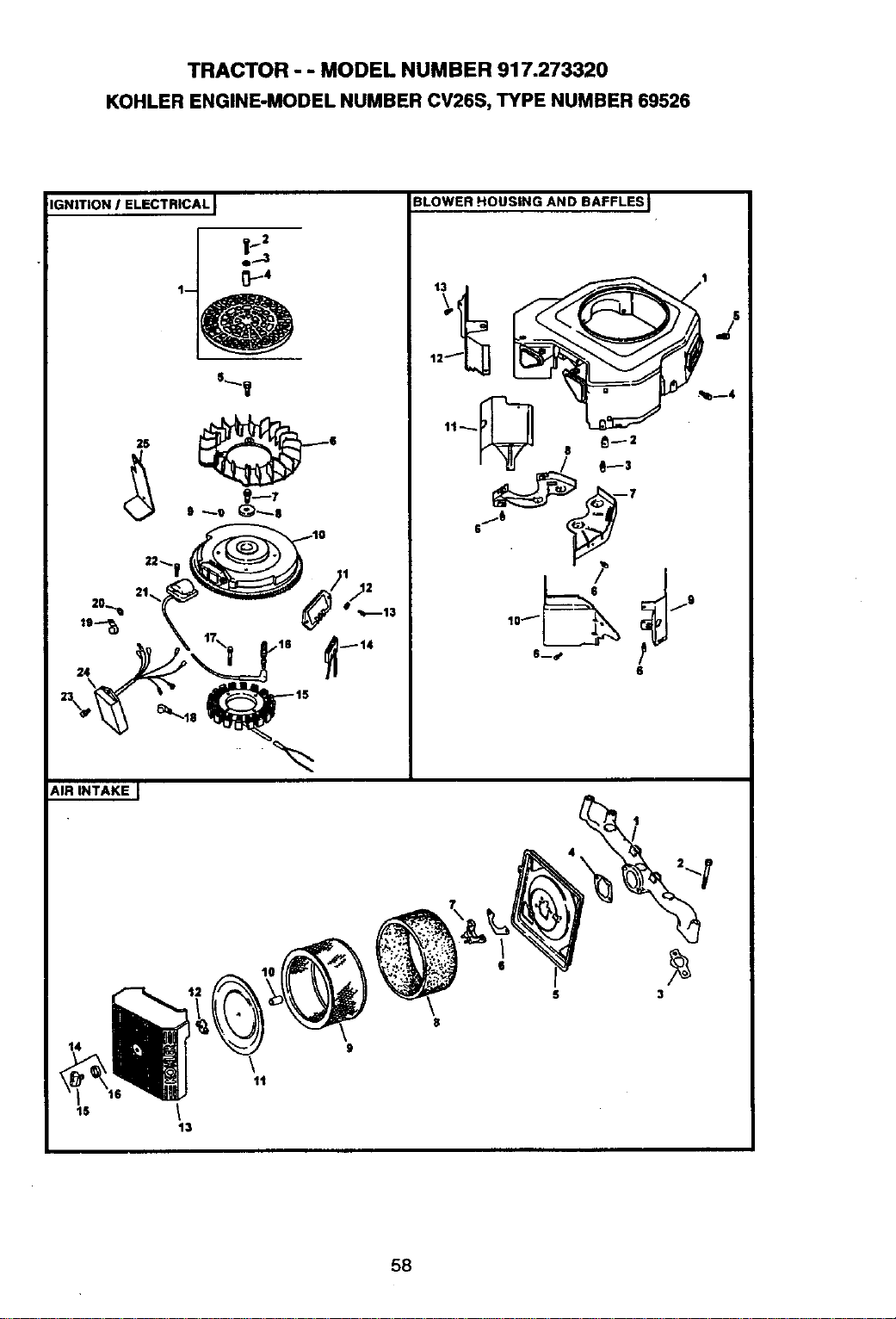
TRACTOR - - MODEL NUMBER 917.273320
KOHLER ENGINE-MODEL NUMBER CV26S, TYPE NUMBER 69526
IIGNITION I ELECTRICALJ
s_y
25
9 _e _8
BLOWER HOUSING AND BAFFLES
6
AIR INTAKE
15
11
13
3
58
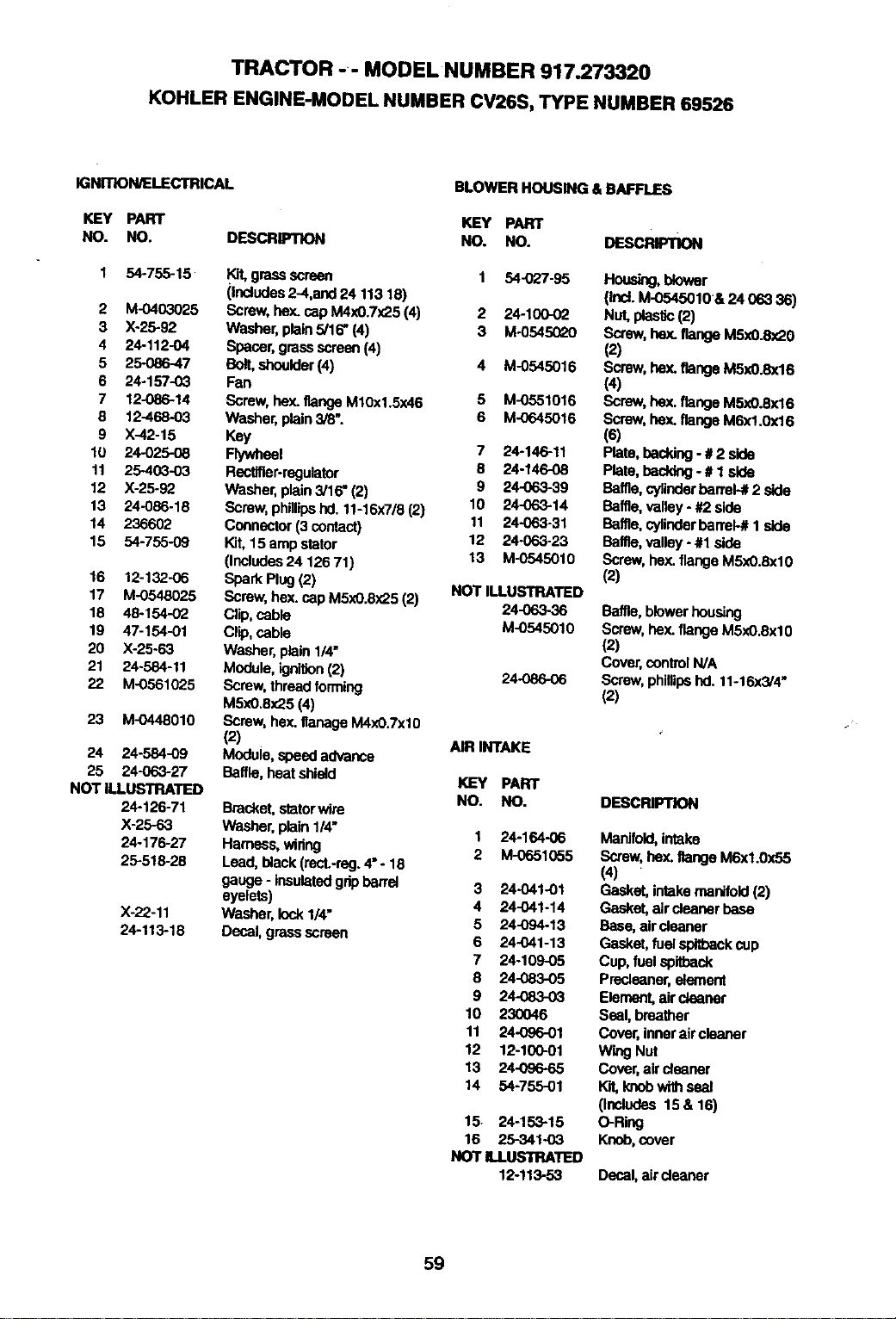
TRACTOR -- MODEL NUMBER 917.273320
KOHLER ENGINE-MODEL NUMBER CV26S, TYPE NUMBER 69526
IGNITION/ELECTRICAL
KEY PART
NO. NO, DESCRIPTION
1 54-755-15
2 M-0403025
3 X-25-92
4 24-112-04
5 25086-47
6 24-157-03
7 12-086-14
8 12-468-03
9 X-42-15
10 24-025-08
11 25-403-03
12 X-25.92
13 24-086-18
14 236602
15 54-755-09
16 12-132-06
17 M-0548025
18 48-154.-,02
19 47-154-01
20 X-25-63
21 24-584-11
22 M-0561025
23 M-0448010
24 24-584-09
25 24-063-27
NOT ILLUSTRATED
24-126-71
X-25-63
24-176-27
25-518-28
X-22-11
24-113-18
_ 9rassscrean
(includes2-4,and 24 113 18)
Screw,hey,.capM4xO.7x25(4)
Washer, pta'm5/16" (4)
Spacer,grassscreen(4)
Bolt,shoulder(4)
Fan
Screw, he)(.flangeM10x1.5x46
Washer,plain3/8".
Key
Flywheel
Rectifier-regulator
Washer, plain3/16" (2)
Screw, phillipshd. 11-16x7/8(2)
Connector(3 contact)
Kit, 15 amp stator
(Includes24 126 7t)
Spark Plug (2)
Screw, hex. capMSxO.8x25(2)
Clip, cable
Clip, cable
Washer, plain1/4"
Module, ignition(2)
Screw, thread forming
MSxO.Sx25(4)
Screw, hex. flanagaM4x0.Txl0
(2)
Module, speed advance
Baffle,heat shield
Bracket,statorwire
Washer, plain 1/4"
Hamess, wiring
Lead, blaok(recL-reg.4" - 18
gauge- insulatedgdpbarrel
eyelets)
Washer, lock 1/4"
Decal, grassscreen
BLOWER HOUSING & BAFFLES
KEY PART
NO. NO. DESCRIPTION
1 54-(_'/-95 Hous_g, tt,ower
(Ind.M-0545010&24063 36)
2 24-100-0_ Nut,pbstlo(2)
3 M-05450L>O Screw,hey,.flange M5x0.Sx20
(2)
4 M-0545016 Screw, hey,.flange M5x0.8x16
(4)
5 M-0551016 Screw,hex. flangeM5x0.Sx16
6 M-0645016 Screw,hex. flange M6xl.0x16
(s)
7 24-146-11 Plate, baddng -# 2 side
8 24-146-08 Plate, backing- # 1 side
9 24-063-39 Betf_, _ barre_# 2 side
10 24-063-14 Baffle, valley- #2 side
11 24-063-31 Baffle,cylinderbarrel-# 1 side
12 24-063-23 Baffle,wiley- #1 side
13 M-0545010 Screw,hex.flangeM5x0.Sxl0
(2)
NOT ILLUSTRATEO
24-06.3-36 Baffle, blowerhousing
M-0545010 Screw,hey..flangeM5x0.8xl 0
(2)
Cover,control N/A
24-086-06 Screw,phillipshd. 11-16x3/4"
(2)
AIR INTAKE
KEY PART
NO. NO. DESCRIPTION
1 24-164-06 Manifold,intake
2 M-0651055 Screw,hex. flangeM6xl.0_5
(4)
3 24-041-01 Gasket,intakemanifold(2)
4 24-041-14 Gasket, aircleaner base
5 24-094-13 Base, aircleaner
6 24-O41-13 Gasket,fuel spltbankcup
7 24-109-05 Cup, fuel spitback
8 24-083-05 Preclcaner,aiement
9 24-083-03 Element, aircleaner
10 230046 Seat,breather
11 24-096-01 Cover,innerair cleaner
12 12-100-01 WingNut
13 24-096-65 Cover,ak"cleaner
14 54-755-01 Kit,knobwithseal
(Includes 15 & 16)
15. 24-153-15 O-Rir_
16 25-341-03 Knob,cover
NOT ILLUSTRATED
12-113-53 Decal, airdeax'_r
59
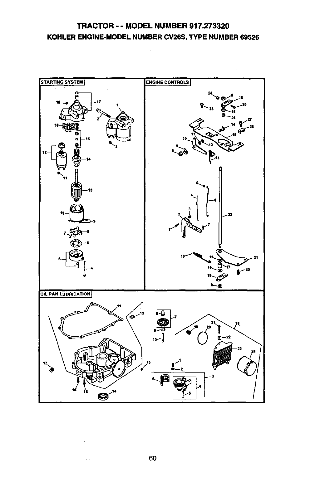
TRACTOR - - MODEL NUMBER 917.273320
KOHLER ENGINE-MODEL NUMBER CV26S, TYPE NUMBER 69526
TARTING SYSTEM J
_-°
°_---4
OtL PAN LUBRICATION I
17,
ENGINE CONTROLS I
24 °
ef jl0
_ _20 _.l_
_14 I_ _20
I.- o
• 60
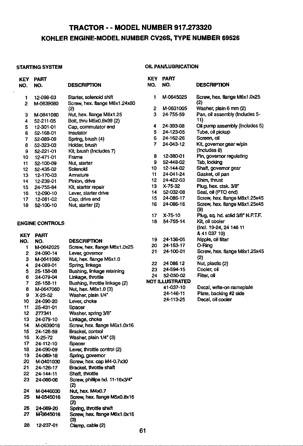
TRACTOR - - MODEL NUMBER 917.273320
KOHLER ENGINE-MODEL NUMBER CV26S, TYPE NUMBER 69526
STARTING SYSTEM
KEY PART
NO. NO.
1 12-096-03
2 M-0839080
3 M-0841080
4 52-211-05
5 12-301-01
6 52-168-01
7 52-089-09
6 52-323-03
9 52-221-01
10 12-471.01
11 52-100-09
12 52-435-02
13 12-170-03
14 12-239-O1
15 24-755-84
16 12-090-10
17 12-081-02
18 52-100-10
ENGINE CONTROLS
KEY PART
NO. NO.
1 M-O642025
2 24-090-14
3 M-0641060
4 24-089-01
5 25-158-08
6 24-079-04
7 25-158-11
8 M-0647060
9 X-26-52
10 24-090-20
11 25-431-01
12 277341
13 24-079-10
14 M-0639016
15 24-126-59
16 X-25-72
17 24-112-10
18 24-090-09
19 _4-089-18
20 M-0401030
21 24-126-17
22 24-144-11
23 24-086-06
24 M-0446030
25 M-0545016
26 24-089-20
27 _064s016
28 12-237-01
DESCRIPTION
Starter,solenoidshift
Screw,hex. flange M8x1.24x80
(2)
Nut, hex. flangeM8xl.25
Bolt,thruMSx0.Sx99(2)
Cap, commutatorend
Insulator
Spring,brush(4)
Holder,brush
Kit,brush(Includes7)
Frame
NUt,starter
Solenoid
Armature
Pinion,drive
Kit,starterrepair
Lever,starterdrive
Cap, driveend
Nut, starter(2)
DESCRIPTION
Screw, hex.flange M6x1.0x25
Lever,governor
Nut,hex. flangeM6xl.0
Spring,linkage
Bushing,linkageretaining
Unkage, throttle
Bushing,throftlalinkage(2)
Nut,hex. M6xl.0 (3)
Washer, plain1/4"
Lever,choke
Spacer
Washer, epdng 3/8"
Linkage,choke
Screw, hex. flar_e M6x1.0x16
Bracket,control
Washer, plain1/4"(3)
Spacer
Lever,throttlecontrol (2)
Spdng, govemor
Screw. hex.cap M4-0.7x30
Bmcket, thmtfteshaft
Shaft, thm_e
Screw, phillipshd. 11-16x3/4"
(2)
Nut,hex. M4x0.7
Screw, hex. flange M5xO.8x16
(2)
Spring,thmt_e shaft
Screw,hey..flangeM6x1.0x16
(3)
Clamp, cable (2)
OIL PAN/LUBRICATION
KEY PART
NO. NO. DESCRIPTION
1 M-0645025
2 M-06310O5
3 24-755-59
4 24-393-08
5 24-123-05
6 24-162-26
7 24-043-12
8 12-380-01
9 52-448-02
10 12-144-o2
11 24-o41-24
12 24-422-03
13 X-75-32
14 52-032-08
15 24-086-17
16 24-086-16
17 Xo76-1O
18 54-755-14
19 24-136-o5
20 24-153-17
21 24-1oo-ol
22 2408612
23 24-594-15
24 52-050-02
NOT ILLUSTRATED
41-037-10
24-146-11
24-113-25
Screw, hex.flange M6x1.Ox25
(2)
Washer,plain6 mm (2)
Pan, oilassembly(Includes5-
11)
Oil pumpassembly(includes5)
Tube, oilpickup
Screen, oil
Kit,governorgearw/pin
(includes6)
Pin,govemor regulating
Tab,locking
Shaft, governorgear
Gasket, oilpan
Shim, thrust
Plug,hex. ctak.3/8"
Seal, oil (PTO end)
Screw, hex.flange M6x1.25x45
Screw, hex. flange M6x1.25x45
(9)
Plug,sq.hd. solid3/8"N.P.T.F.
Kit,oilcooler
(Incl. 19-24, 24 146 11
&41037 10)
Nipple,oil filter
O-Ring
Screw,hax. flangeMSx1.25x45
(2)
Nut,plastic(2)
Cooler,oil
Filter,oil
Decal, write-onnameplate
Plate, backing#2 side
Decal, oilcooler
61
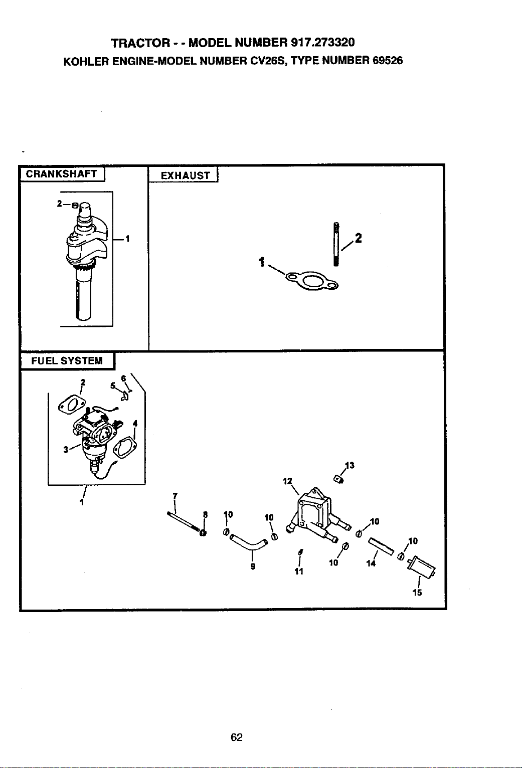
TRACTOR - - MODEL NUMBER 917.273320
KOHLER ENGINE-MODEL NUMBER CV26S, TYPE NUMBER 69526
CRANKSHAFT j
ml
EXHAUST I
FUEL SYSTEM I
!
/
1
12 _3
_ lo ,o ,,,o
I 10 14
9 11
1-
15
62
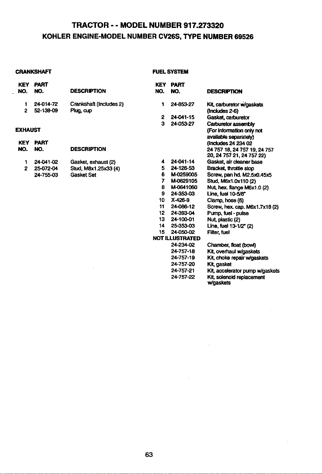
TRACTOR - - MODEL NUMBER 917.273320
KOHLER ENGINE-MODEL NUMBER CV26S, TYPE NUMBER 69526
CRANKSHAFT
KEY PART
NO. NO.
1 24-014.72
2 52-139-09
EXHAUST
KEY PART
NO. NO.
1 24-041-02
2 25-072-04
24-755-03
FUEL SYSTEM
KEY PART
DESCRIPTION NO. NO.
Crankshaft(includes2) 1 24-8.53-27
Plug,cup
2 24-041-15
3 24-053-27
DESCRIPTION
Gasket, exhaust (2)
Stud, MSx1.25x33 (4)
Gasket Set
4 24-041-14
5 24-126-53
6 M-0259005
7 M-0629105
8 M-0641060
9 24-353-03
10 X-426-9
11 24-086-12
12 24-393-04
13 24-100-01
14 25-353-03
15 24-050-02
NOT ILLUSTRATED
24-2_02
24-757-18
24-757-19
24-757-20
24-757-21
24-757-22
DESCRIPTION
Kit,cadxmorW/gaskets
0ndudas 2-6)
Gasket, cad_Jretor
ca_oumtoraasemuy
(For|nfonnationonlynot
availableseparately)
(Incfudes24 234 02
24 757 18, 24 757 19, 24 757
20, 24 757 21, 24 757 22)
Gasket, aircleanerbase
Bracket,throt_estop
Screw,pan hd. M2.5x0.45x5
Stud, MSxl.0x110 (2)
Nut, hex.flangeM6xl.0 (2)
Line,fuel 10-5/8"
C_O, ho_ (6)
Screw,hex. cap. M6xl.Tx18 (2)
Pump,fuel- pulse
Nut, _ (2)
Line,fuel 13-1/2" (2)
Filter,fuel
Chamber,float(bo_)
Kit, overhaulw/gaskets
Kit,choke repairw/gaskets
Kit, gasket
Kit, acceleratorpumpw/gaskets
Kit, solenoidreplacement
w/gaskets
63
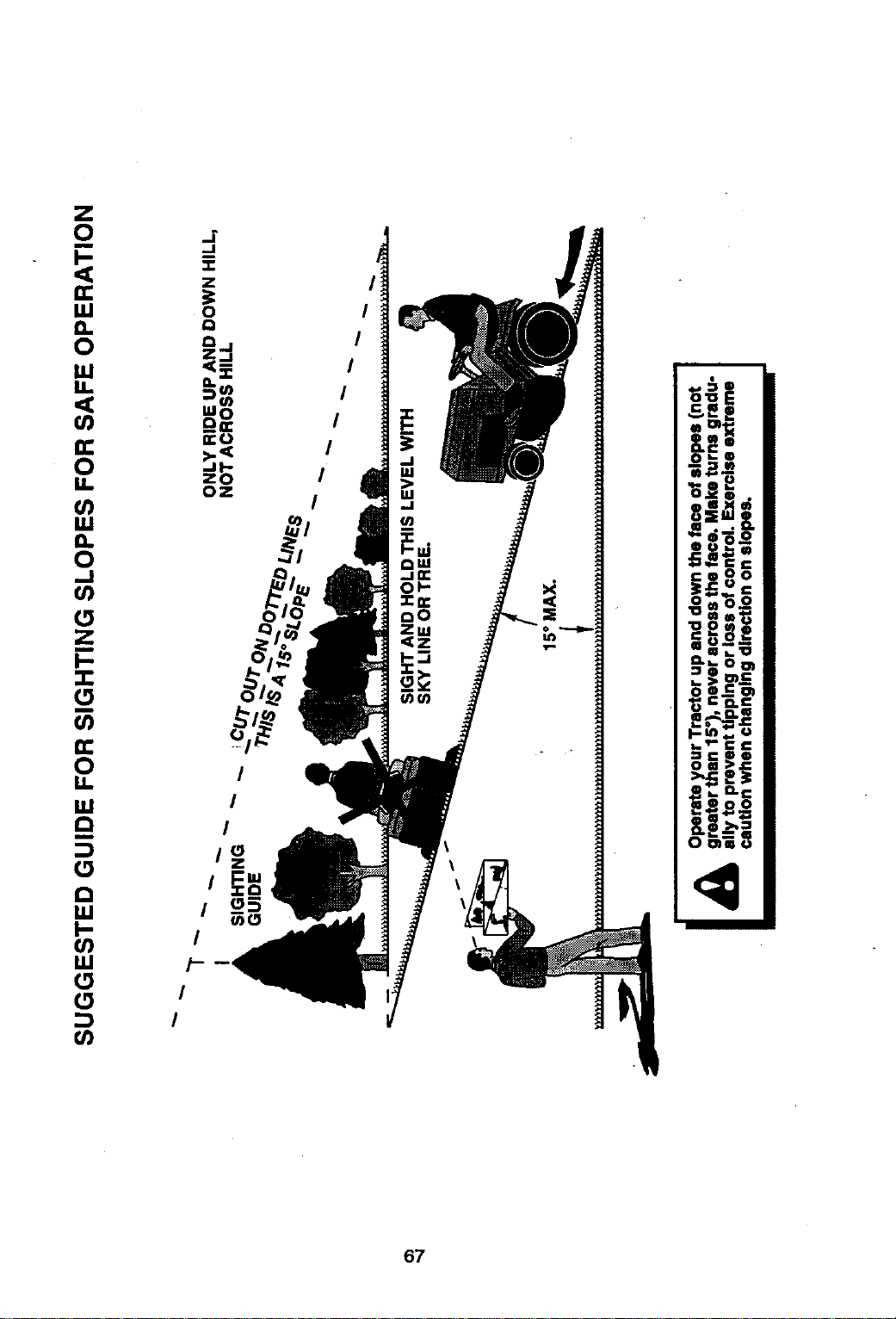
67
For the repair or replacement parts you need
delivered directly to your home
Call 7 am - 7 pm, 7 days a week
1-800-366-PART
(1-800-366-7278)
Para ordenar piezas con entrega a
domicilio - 1-800-659-7084
For in-house major brand repair service
Call 24 hours a day, 7 days a week
1-800-4-REPAIR
(1-800-473-7274)
Para pedir servicio de reparaci6n a
domicilio - 1-800-676-5811
For the location of a Sears Parts and
Repair Center in your area
Call 24 hours a day, 7 days a week
1-800-488-1222
For information on purchasing a Sears
Maintenance Agreement or to inquire
about an existing Agreement
Call 9 am - 5 pm, Monday-Saturday
1-800-827-6655
When requesting service or ordering
pads, always providethe following
information:
• Product Type • Part Number
• Model Number ° Part Description
SEARS
Amenca's Repaor Specialists
164178 Rev. 4 7.20.98 JH/TR/JH/RH Printed in U.S.A.