
Operator's Manual
CRRFT MRH °
GA
26.O HR* 54"
Electric Start
TRACTO
Mower
6 Speed Transaxle
Model No.
917.25024
, EspaSol, p. 36
]
This product has a low emission engine which operates /
differently from previously built engines. Before start the
you
1
engine, read and understand this Operator's Manual.
IMPORTANT: For answers to your questions
Read and follow all Safety about this product, Call:
Rules and Instructions before 1-800-659-5917
Sears Craftsman Help Line
operating this equipment. 5 am- 5 pm, Mon- Sat
Gasoline containing up to 10% ethanol (El0) is acceptable for use in this machine.
The use of any gasoline exceeding 10% ethanol (El0) will void the product warranty,
Esta maquina puede utilizar gasolina con un contenido de hasta el 10% de etanol (El0).
El uso de una gasolina que supere el 10% de etanol (El0) anulara la garantia del producto,
Sears Brands Management Corporation, Hoffman Estates, IL 60179 U.S.A.
Visit our Craftsman website:www.sears.com/craftsman *Asratedbytheenginemanufacturer
581923149
Warranty .................................................. 2 Maintenance .......................................... 20
Safety Rules ............................................ 3 Service and Adjustments ....................... 25
Product Specifications ............................. 6 Storage .................................................. 30
Assembty/Pre-Operation ......................... 8 Troubleshooting ..................................... 31
Operation ............................................... 13 Sears Service .......................... Back Cover
Maintenance Schedule .......................... 20
Craftsman Riding Equipment Warranty
CRAFTSMAN FULL WARRANTY
FOR TWO YEARS from the date of purchase, all non-expendable parts of this riding equipment are
warranted against any defects in material or workmanship. A defective non-expendable part will
receive free in-home repair or replacement if repair is impossible.
FOR FIVE YEARS from the date of purchase, the frame and front axle of this riding equipment are
warranted against any defects in material or workmanship. A defective frame or front axle will receive
free in-home repair or replacement if repair is impossible.
FOR 90 DAYS from the date of purchase, the battery (an expendable part) of this riding equipment
is warranted against any defects in material or workmanship (our testing proves that it will not hold a
charge). A defective battery will receive free in-home replacement.
ADDITIONAL LIFETIME LIMITED WARRANTY on CAST IRON FRONT AXLE (if equipped)
FOR AS LONG AS IT IS USED by the original owner after the fifth year from the date of purchase, the
cast iron front axle (if equipped) of this riding equipment is warranted against any defects in material or
workmanship. With proof of purchase, a defective cast front axle will receive free in-home replacement.
WARRANTY SERVICE
For warranty coverage details to obtain free repair or replacement, call 1-800-659-5917 or visit the
web site: www.craftsman.com
in all cases above, if part repair or replacement is impossible, the riding equipment will be replaced
free of charge with the same or an equivalent model.
All of the above warranty coverage is void if this riding equipment is ever used while providing
commercial services or if rented to another person.
This warranty covers ONLY defects in material and workmanship. Warranty coverage does NOT
include:
• Expendable parts (except battery) that can wear out from normal use within the warranty period,
including but not limited to blades, spark plugs, air cleaners, belts, and oil filters.
• Standard maintenance servicing, oil changes, or tune-ups.
• Tire replacement or repair caused by punctures from outside objects, such as nails, thorns,
stumps, or glass.
• Tire or wheel replacement or repair resulting from normal wear, accident, or improper operation or
maintenance.
• Repairs necessary because of operator abuse, including but not limited to damage caused by
towing objects beyond the capability of the riding equipment, impacting objects that bend the
frame, axle assembly or crankshaft, or over-speeding the engine.
• Repairs necessary because of operator negligence, including but not limited to, electrical and
mechanical damage caused by improper storage, failure to use the proper grade and amount
of engine oil, failure to keep the deck clear of flammable debris, or failure to maintain the riding
equipment according to the instructions contained in the operator's manual.
• Engine (fuel system) cleaning or repairs caused by fuel determined to be contaminated or oxidized
(stale). In general, fuel should be used within 30 days of its purchase date.
• Normal deterioration and wear of the exterior finishes, or product label replacement.
This warranty gives you specific legal rights, and you may also have other rights which vary from
state to state.
Sears Brands Management Corporation, Hoffman Estates, IL 60179
2
_,DANGER: This cutting machine is capable of amputating hands and feet and
throwing objects. Failure to observe the following safety instructions could result
in serious injury or death.
_WARNING: In order to prevent acciden-
tal starting when setting up, transporting,
adjusting or making repairs, always discon-
nect spark plug wire and place wire where
it cannot contact spark plug.
_,WARNING: Do not coast down a hill in
neutral, you may lose control of the tractor.
,_WARNING: Tow only the attachments
that are recommended by and comply with
specifications of the manufacturer of your
tractor. Use common sense when towing.
Operate only at the lowest possible speed
when on a slope. Too heavy of a load, while
on a slope, is dangerous. Tires can lose
traction with the ground and cause you to
lose control of your tractor.
_IbWARNING: Engine exhaust, some of
its constituents, and certain vehicle compo-
nents contain or emit chemicals known to
the State of California to cause cancer and
birth defects or other reproductive harm.
_,WARNING: Battery posts, terminals and
related accessories contain lead and lead
compounds, chemicals known to the State of
California to cause cancer and birth defects
or other reproductive harm. Wash hands
after handling.
I. GENERAL OPERATION
• Read, understand, and follow all instruc-
tions on the machine and in the manual
before starting.
° Do not put hands or feet near rotating
parts or under the machine. Keep clear
of the discharge opening at all times.
• Only allow responsible adults, who are
familiar with the instructions, to operate
the machine.
° Clear the area of objects such as rocks,
toys, wire, etc., which could be picked
up and thrown by the blades.
° Be sure the area is clear of bystanders
before operating. Stop machine ifanyone
enters the area.
• Never carry passengers.
° Do not mow in reverse unless absolutely
necessary. Always took down and behind
before and while backing.
• Never direct discharged materialtoward
anyone. Avoid discharging material
against a wall or obstruction. Material
may ricochet back toward the operator.
Stop the blades when crossing gravel
surfaces.
• Do not operate machine without the en-
tire grass catcher, discharge chute, or
other safety devices in place and working.
• Slow down before turning.
• Never leave a running machine unat-
tended. Always turn off blades, set
parking brake, stop engine, and remove
keys before dismounting.
• Disengage blades when not mowing.
Shut off engine and wait for all parts to
come to a complete stop before cleaning
the machine, removing the grass catcher,
or unclogging the discharge chute.
° Operate machine only in daylight or good
artificial light.
• Do not operate the machine while under
the influence of alcohol or drugs.
• Watch for traffic when operating near or
crossing roadways.
• Use extra care when loading or unloading
the machine into a trailer or truck.
• Atwayswear eye protection when operat-
ing machine.
• Data indicates that operators, age 60
years and above, are involved in a large
percentage of riding mower-related inju-
ries. These operators should evaluate
their ability to operate the riding mower
safely enough to protect themselves and
others from serious injury.
• Followthemanufacturer'srecommenda-
tion for wheel weights or counterweights.
• Keep machine free of grass, leaves or
other debris build-up which can touch hot
exhaust / engine parts and burn. Do not
allow the mower to plow leaves or other
debris which can cause build-up to oc-
cur. Clean any oil or fuel spillage before
operating or storing the machine. Allow
machine to cool before storage.
II.SLOPEOPERATION
Slopesareamajorfactorrelatedtolossof
controlandtip-overaccidents,whichcan
resultinsevereinjuryordeath.Operation
onallslopesrequiresextra caution. If you
cannot back up the slope or ifyou feel uneasy
on it, do not mow it.
* Mow up and down slopes, not across.
* Watch for holes, ruts, bumps, rocks, or
other hidden objects. Uneven terrain
could overturn the machine. Tall grass
can hide obstacles.
* Choose a low ground speed so that you
will not have to stop or shift while on the
slope.
* Do not mow on wet grass. Tires may lose
traction.
Always keep the machine in gear when
going down slopes. Do not shiftto neutral
and coast downhill.
* Avoid starting, stopping, or turning on a
slope. Ifthetires Iosetraction, disengage
the blades and proceed slowly straight
down the slope.
* Keep all movement on the slopes slow
and gradual. Do not make sudden
changes in speed or direction, which
could cause the machine to roll over.
* Use extra care while operating machine
with grass catchers or other attachments;
they can affect the stability of the ma-
chine. Do no use on steep slopes.
* Do not try to stabilize the machine by
putting your foot on the ground.
* Do not mow near drop-offs, ditches,
or embankments. The machine could
suddenly roll over if a wheel is over the
edge or if the edge caves in.
Ill. CHILDREN
_,WARNING: CHILDREN CAN BE INJURED
BY THIS EQUIPMENT.The American Acade-
my of Pediatrics recommends that children
be a minimum of 12 year of age before op-
erating a pedestrian controlled lawn mower
and a minimum of 16 years of age before
operating a riding lawn mower.
Tragic accidents can occur if the operator
is not alert to the presence of children.
Children are often attracted to the machine
and the mowing activity. Never assume
that children will remain where you last
saw them.
* Keep children out of the mowing area
and in the watchful care of a responsible
adult other than the operator.
* Be alert and turn machine off if a child
enters the area.
* Before and while backing, look behind
and down for small children.
* Never carrychildren, evenwith the blades
shutoff. They may fatl offand be seriously
injured or interfere with safe machine
operation. Children who have been given
rides in the past may suddenly appear in
the mowing area for another ride and be
run over or backed over by the machine.
* Never allow children to operate the ma-
chine.
* Use extra care when approaching blind
corners, shrubs, trees, or other objects
that may block your view of a child.
IV. TOWING
* Tow only with a machine that has a hitch
designed for towing. Do not attach towed
equipment except at the hitch point.
* Followthemanufacturer'srecommenda-
tion for weight limits for towed equipment
and towing on slopes.
* Never allow children or others in or on
towed equipment.
* On slopes,theweightofthetowed equip-
ment may cause loss of traction and toss
of control.
* Travel slowly and allow extra distance to
stop.
V. SERVICE
SAFE HANDLING OF GASOLINE
To avoid personal injury or property dam-
age, use extreme care in handling gasoline.
Gasoline is extremely flammable and the
vapors are explosive.
* Extinguish all cigarettes, cigars, pipes,
and other sources of ignition.
Use only approved gasoline container.
Never remove gas cap or add fuel with
the engine running. Allow engine to cool
before refueling.
Never fuel the machine indoors.
Never store the machine or fuel container
where there is an open flame, spark, or
pilot light such as on a water heater or
other appliances.
Never fill containers inside a vehicle or
on a truck or trailer bed with plastic liner.
Always place containers on the ground
away from your vehicle when filling.
4
• Removegas-poweredequipmentfrom
thetruckortrailerandrefuelit onthe
ground.Ifthisisnotpossible,thenrefuel
suchequipmentwithaportablecontainer,
ratherthanfroma gasolinedispenser
nozzle.
• Keepthenozzleincontactwiththerim
ofthefueltankorcontaineropeningat
alltimesuntilfuelingiscomplete.Donot
usea nozzlelock-opendevice.
• Iffuetisspilledonclothing,changecloth-
ingimmediately.
• Neveroverfillfueltank.Replacegascap
andtightensecurely.
GENERALSERVICE
• Neveroperatemachineinaclosedarea.
• Keepallnutsandboltstighttobesurethe
equipmentisinsafeworkingcondition.
• Nevertamperwithsafetydevices.Check
theirproperoperationregularly.
• Keepmachinefreeofgrass,leaves,or
otherdebrisbuild-up.Cleanoilorfuel
spillageandremoveanyfuel-soakedde-
bris.Allowmachinetocoolbeforestoring.
• Ifyoustrikea foreignobject,stopand
inspectthemachine.Repair,ifnecessary,
beforerestarting.
• Nevermakeanyadjustmentsorrepairs
withtheenginerunning.
• Checkgrasscatchercomponentsandthe
dischargechutefrequentlyandreplace
withmanufacturer'srecommendedparts,
whennecessary.
• Mowerbtadesaresharp.Wrapthebtade
orweargloves,anduseextracaution
whenservicingthem.
• Checkbrakeoperationfrequentty.Adjust
andserviceasrequired.
• Maintainorreptacesafetyandinstruction
labels,asnecessary.
• Besuretheareaisclearofbystanders
beforeoperating.Stopmachineifanyone
entersthearea.
• Nevercarrypassengers.
• Donotmowinreverseunlessabsolutely
necessary.Alwaystookdownandbehind
beforeandwhilebacking.
• Nevercarrychildren,evenwiththe
bladesshutoff. Theymayfalloffand
beseriouslyinjuredorinterferewithsafe
machineoperation.Childrenwhohave
beengivenridesinthepastmaysuddenly
appearinthemowingareaforanother
rideandberunoverorbackedoverby
themachine.
• Keepchildrenoutofthemowingarea
andinthewatchfulcareofaresponsible
adultotherthantheoperator.
• Bealertandturnmachineoffif a child
entersthearea.
• Beforeandwhilebacking,lookbehind
anddownforsmallchildren.
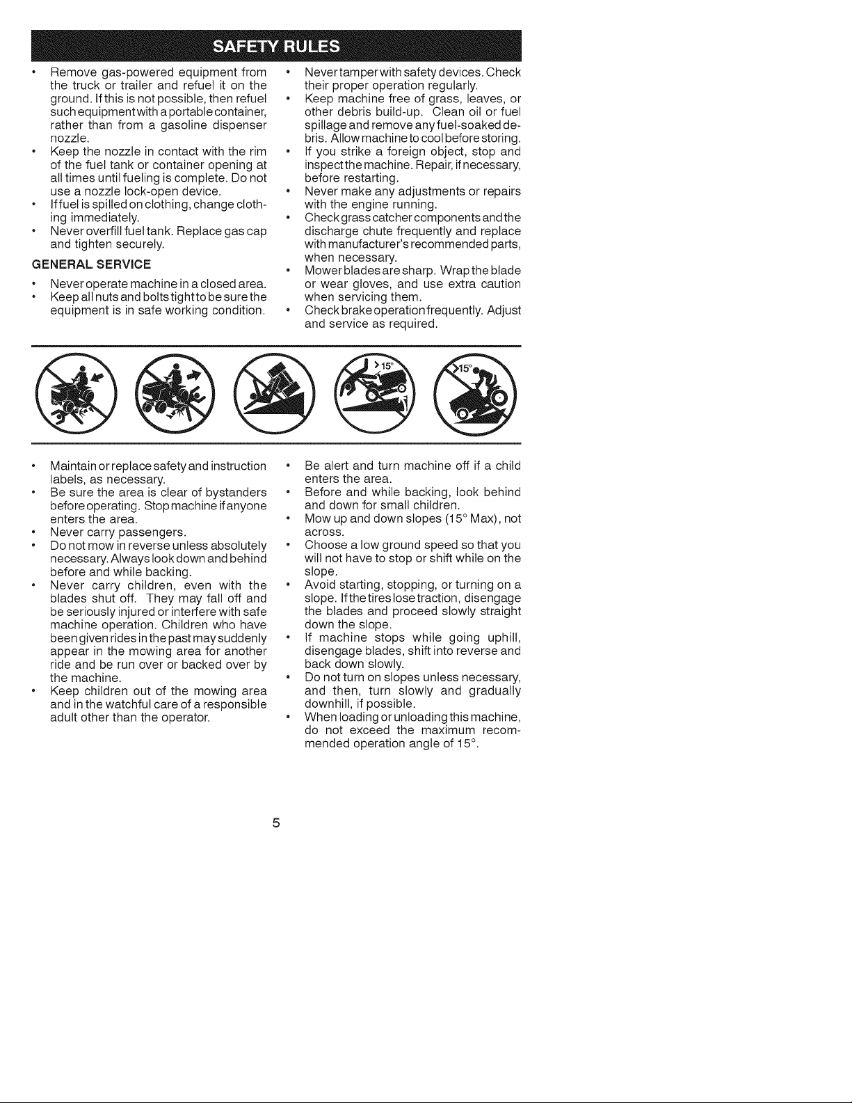
• Mowupanddownslopes(15°Max),not
across.
• Choosealowgroundspeedsothatyou
willnothavetostoporshiftwhileonthe
slope.
• Avoidstarting,stopping,orturningona
slope.Ifthetireslosetraction,disengage
thebladesandproceedslowlystraight
downtheslope.
• If machinestopswhilegoinguphill,
disengageblades,shiftintoreverseand
backdownslowly.
• Donotturnonslopesunlessnecessary,
andthen,turn slowlyandgradually
downhill,ifpossible.
• WhenIoadingoruntoadingthismachine,
do notexceedthe maximumrecom-
mendedoperationangleof15°.
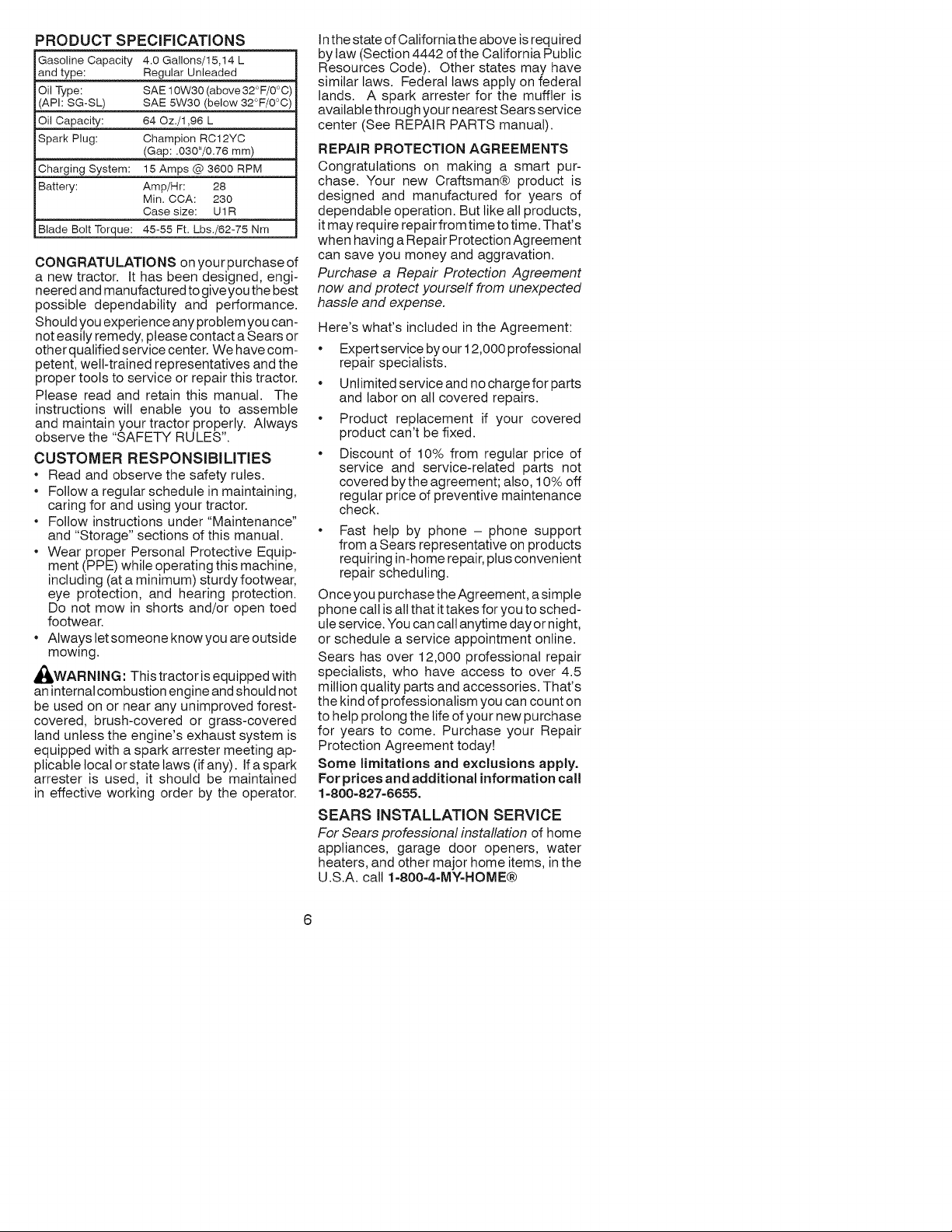
PRODUCTSPECIFiCATiONS
Gasoline Capacity 4.0 Gallons/15,14 L
and type: Regular Unleaded
Oil Type: SAE 10W30 (above 32°F/0°C
(API: SG-SL) SAE 5W30 (below 32°F/0°C
Oil Capacity: 64 Oz./1,96 L
Spark Plug: Champion RC12YC
(Gap: .030"/0.76 mm)
Charging System: 15 Amps @ 3600 RPM
Battery: Amp/Hr: 28
Min. CCA: 230
Case size: U1R
Blade Bolt Torque: 45-55 Ft. Lbs./62-75 Nm
CONGRATULATIONS on your purchase of
a new tractor. It has been designed, engi-
neered and manufactured to give you the best
possible dependability and performance.
Should you experience any problem you can-
not easily remedy, please contact a Sears or
other qualified service center. We have com-
petent, welt-trained representatives and the
proper tools to service or repair this tractor.
Please read and retain this manual. The
instructions will enable you to assemble
and maintain your tractor properly. Always
observe the "SAFETY RULES".
CUSTOMER RESPONSIBILITIES
* Read and observe the safety rules.
* Follow a regular schedule in maintaining,
caring for and using your tractor.
* Follow instructions under"Maintenance"
and "Storage" sections of this manual.
* Wear proper Personal Protective Equip-
ment (PPE) while operating this machine,
including (at a minimum) sturdy footwear,
eye protection, and hearing protection.
Do not mow in shorts and/or open toed
footwear.
* Always tetsomeone know you are outside
mowtng.
_WARNING: This tractor is equipped with
an internal combustion engine and should not
be used on or near any unimproved forest-
covered, brush-covered or grass-covered
land unless the engine's exhaust system is
equipped with a spark arrester meeting ap-
plicable local or state laws (if any). If a spark
arrester is used, it should be maintained
in effective working order by the operator.
In the state of California the above is required
by taw (Section 4442 of the California Public
Resources Code). Other states may have
similar laws. Federal laws apply on federal
lands. A spark arrester for the muffler is
available through your nearest Sears service
center (See REPAIR PARTS manual).
REPAIR PROTECTION AGREEMENTS
Congratulations on making a smart pur-
chase. Your new Craftsman@ product is
designed and manufactured for years of
dependable operation. But like all products,
it may require repair from time to time. That's
when having a Repair Protection Agreement
can save you money and aggravation.
Purchase a Repair Protection Agreement
now and protect yourself from unexpected
hassle and expense.
Here's what's included in the Agreement:
Expert service by our 12,000 professional
repair specialists.
U ntimited service and no charge for parts
and labor on all covered repairs.
Product replacement if your covered
product can't be fixed.
Discount of 10% from regular price of
service and service-related parts not
covered bythe agreement; also, 10% off
regular price of preventive maintenance
check.
Fast help by phone - phone support
from a Sears representative on products
requiring in-home repair, plus convenient
repair scheduling.
Once you purchase the Agreement, a simple
phone call is all that it takes for you to sched-
ule service. You can call anytime day or night,
or schedule a service appointment online.
Sears has over 12,000 professional repair
specialists, who have access to over 4.5
million quality parts and accessories. That's
the kind of professionalism you can count on
to help prolong the life of your new purchase
for years to come. Purchase your Repair
Protection Agreement today!
Some limitations and exclusions apply.
For prices and additional information call
1-800=827-6655,
SEARS INSTALLATION SERVICE
For Sears professional installation of home
appliances, garage door openers, water
heaters, and other major home items, inthe
U.S.A. call 1-800-4-MY-HOME@
6
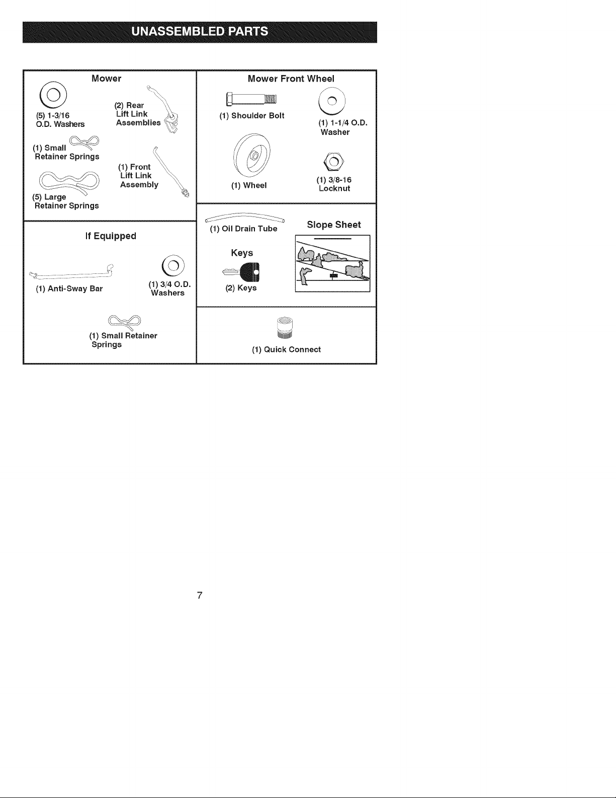
Mower
(2) Rear
(5) 1-3/16 Lift Link
O.D. Washers Assemblies
(1)Sma,
Retainer
Springs
(1) Front _
__ Lift Link _
Assembly _4_
(5) Large
Retainer Springs
if Equipped
(1) Anti-Sway Bar
©
(1) 3/40.D.
Washers
(1) Small Retainer
Springs
Mower Front Wheel
(1) Shoulder Bolt
(1) 1-1/40.D.
Washer
(1) Wheel
(1)3/8q6
Locknut
(1) Oil Drain Tube
Keys
(2) Keys
Slope Sheet
(1) Quick Connect
Your new tractor has been assembled at the factory with exception of those parts left
unassembted for shipping purposes. To ensure safe and proper operation of your tractor
all parts and hardware you assemble must be tightened securely. Use the correct tools
as necessary to insure proper tightness.
TOOLS REQUIRED FOR ASSEMBLY
A socket wrench set will make assembly
easier. Standard wrench sizes are listed.
(2) 7/16" wrenches Utility knife
(1) 1/2" wrench Tire pressure gauge
(1) 3/4" wrench Pliers
(1) 3/4" socket w/drive ratchet
(1) 9/16" wrench Flashlight
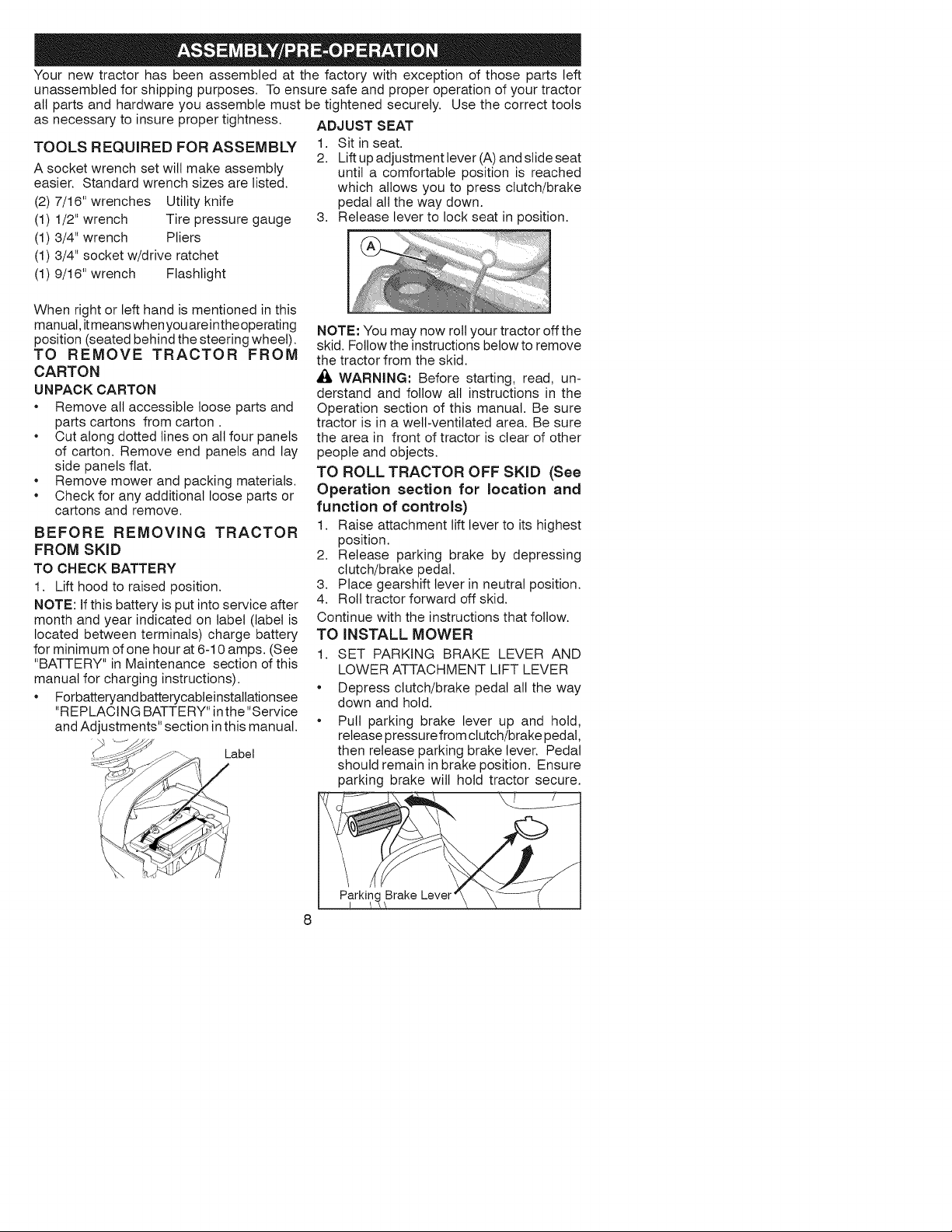
ADJUST SEAT
1. Sit in seat.
2. Lift up adjustment lever (A) and slide seat
until a comfortable position is reached
which allows you to press clutch/brake
pedal all the way down.
3. Release lever to lock seat in position.
When right or left hand is mentioned in this
manual, itmeanswhen you areinthe operating
position (seated behind the steering wheel).
TO REMOVE TRACTOR FROM
CARTON
UNPACK CARTON
* Remove all accessible loose parts and
parts cartons from carton.
* Cut along dotted lines on all four panels
of carton. Remove end panels and lay
side panels flat.
* Remove mower and packing materials.
* Check for any additional loose parts or
cartons and remove.
BEFORE REMOVING TRACTOR
FROM SKID
TO CHECK BATTERY
1. Lift hood to raised position.
NOTE: If this battery is put into service after
month and year indicated on label (label is
located between terminals) charge battery
for minimum of one hour at 6-10 amps. (See
"BATTERY" in Maintenance section of this
manual for charging instructions).
* Forbatteryand batterycabteinstatlationsee
"REPLACING BATTERY" in the "Service
and Adjustments" section in this manual.
-.>_ Label
NOTE: You may now roll your tractor off the
skid. Follow the instructions below to remove
the tractor from the skid.
_i_ WARNING: Before starting, read, un-
derstand and follow all instructions in the
Operation section of this manual. Be sure
tractor is in a well-ventilated area. Be sure
the area in front of tractor is clear of other
people and objects.
TO ROLL TRACTOR OFF SKID (See
Operation section for location and
function of controls)
1. Raise attachment lift lever to its highest
position.
2. Release parking brake by depressing
clutch/brake pedal.
3. Place gearshift lever in neutral position.
4. Roll tractor forward off skid.
Continue with the instructions that follow.
TO INSTALL MOWER
1. SET PARKING BRAKE LEVER AND
LOWER ATTACHMENT LIFT LEVER
Depress clutch/brake pedal all the way
down and hold.
Pull parking brake lever up and hold,
release pressure from clutch/brake pedal,
then release parking brake lever. Pedal
should remain in brake position. Ensure
parking brake wilt hold tractor secure.
Brake Lever
8
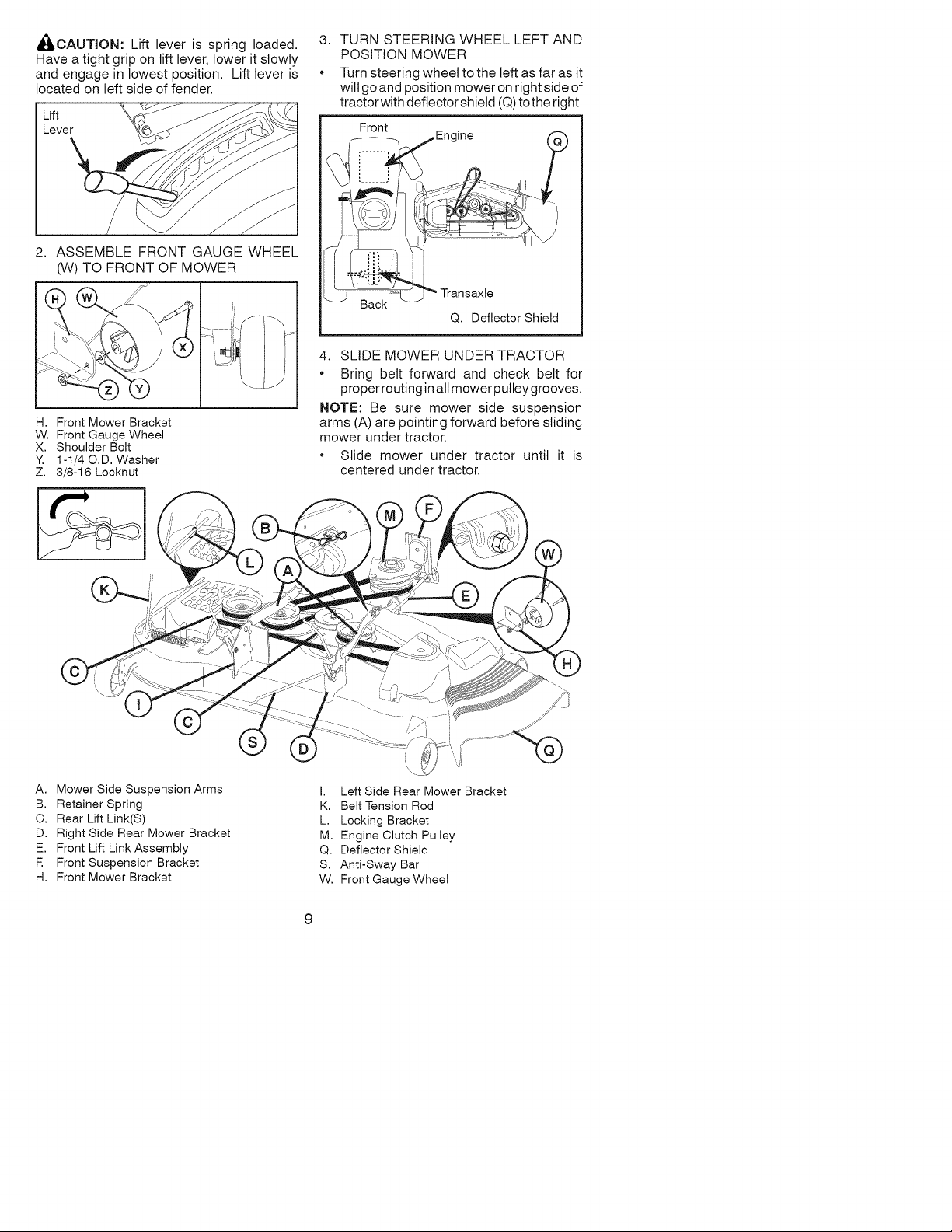
AI_CAUTION: Lift lever is spring loaded.
Have a tight grip on lift lever, lower it slowly
and engage in lowest position. Lift lever is
located on left side of fender.
Lift
Lever
2. ASSEMBLE FRONT GAUGE WHEEL
(W) TO FRONT OF MOWER
3. TURN STEERING WHEEL LEFT AND
POSITION MOWER
Turn steering wheel to the left as far as it
wilt go and position mower on right side of
tractor with deflector shield (Q) to the right.
Front
..... Transaxle
Q. Deflector Shield
H. Front Mower Bracket
W. Front Gauge Wheel
X. Shoulder Bolt
Y. 1-1/40.D. Washer
Z. 3/8-16 Locknut
4. SLIDE MOWER UNDER TRACTOR
Bring belt forward and check belt for
proper routing in all mower pulley grooves.
NOTE: Be sure mower side suspension
arms (A) are pointing forward before sliding
mower under tractor.
Slide mower under tractor until it is
centered under tractor.
A. Mower Side Suspension Arms
B. Retainer Spring
C. Rear Lift Link(S)
D. Right Side Rear Mower Bracket
E. Front Lift Link Assembly
R Front Suspension Bracket
H. Front Mower Bracket
I. Left Side Rear Mower Bracket
K. Belt Tension Rod
L. Locking Bracket
M. Engine Clutch Pulley
Q. Deflector Shield
S. Anti-Sway Bar
W. Front Gauge Wheel
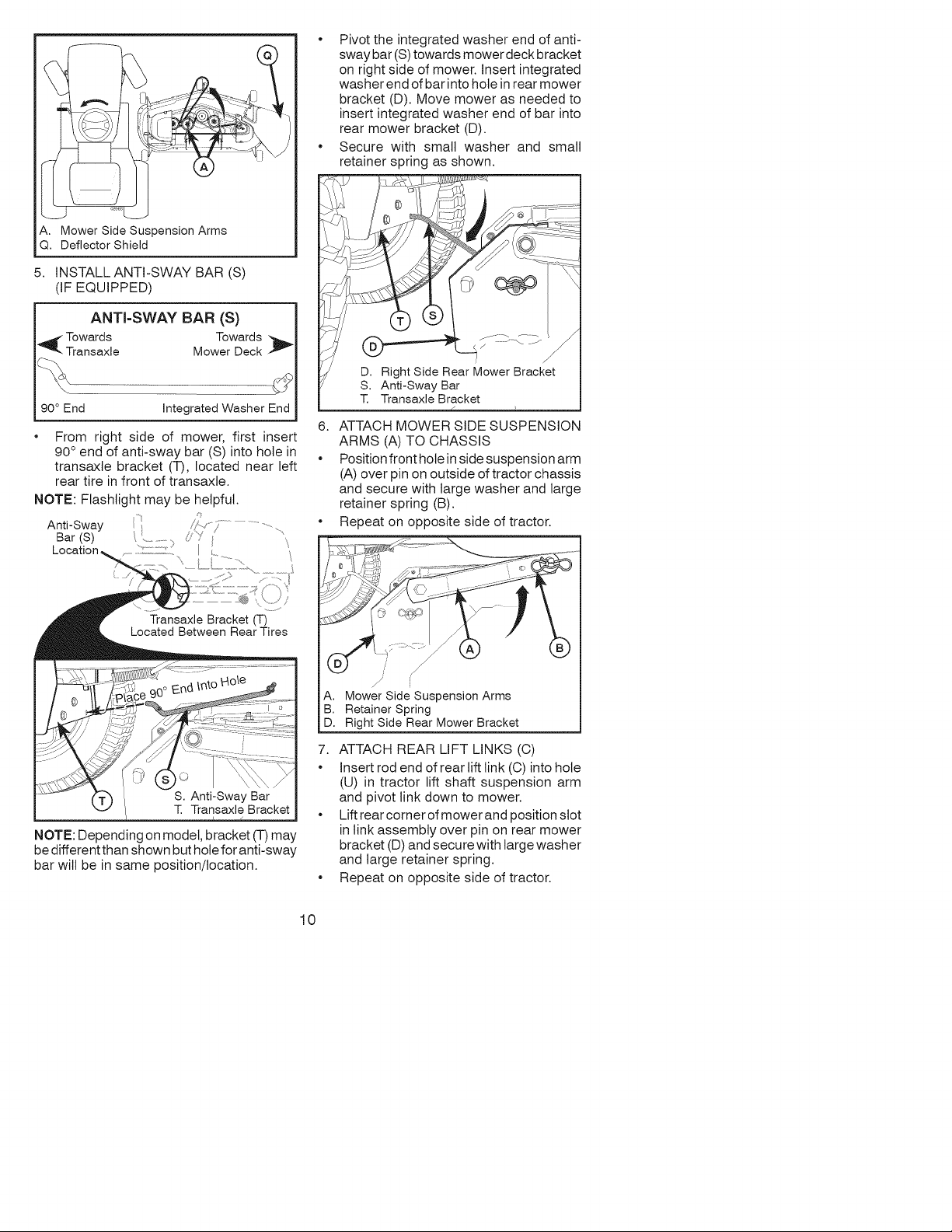
A. MowerSideSuspensionArms
Q.DeflectorShield
5. INSTALL ANTI-SWAY BAR (S)
(IF EQUIPPED)
ANTI-SWAY BAR (S)
_ Towards Towards
Transaxle Mower Deck
90 ° End Integrated Washer End
• From right side of mower, first insert
90 ° end of anti-sway bar (S) into hole in
transaxle bracket (T), located near left
rear tire in front of transaxle.
NOTE: Flashlight may be helpful.
Anti-Sway
Bar (S) ...................
Location, "_...............'"
Transaxle Bracket (T)
Located Between Rear Tires
NOTE: Depending on model, bracket (T) may
be different than shown but hole for anti-sway
bar will be in same position/location.
• Pivot the integrated washer end of anti-
sway bar (S) towards mower deck bracket
on right side of mower. Insert integrated
washer end of bar into hole in rear mower
bracket (D). Move mower as needed to
insert integrated washer end of bar into
rear mower bracket (D).
• Secure with small washer and small
retainer spring as shown.
J
D. Right Side Rear Mower Bracket
S. Anti-Sway Bar
T. Transaxle Bracket
6. ATTACH MOWER SIDE SUSPENSION
ARMS (A) TO CHASSIS
• Position front hote in side suspension arm
(A) over pin on outside of tractor chassis
and secure with large washer and large
retainer spring (B).
• Repeat on opposite side of tractor.
A,
B.
D.
J
J
Mower Side Suspension Arms
Retainer Spring
Right Side Rear Mower Bracket
7. ATTACH REAR LIFT LINKS (C)
• Insert rod end of rear lift link (C) into hole
(U) in tractor lift shaft suspension arm
and pivot link down to mower.
• Lift rear corner of mower and position slot
in link assembly over pin on rear mower
bracket (D) and secure with large washer
and large retainer spring.
• Repeat on opposite side of tractor.
10
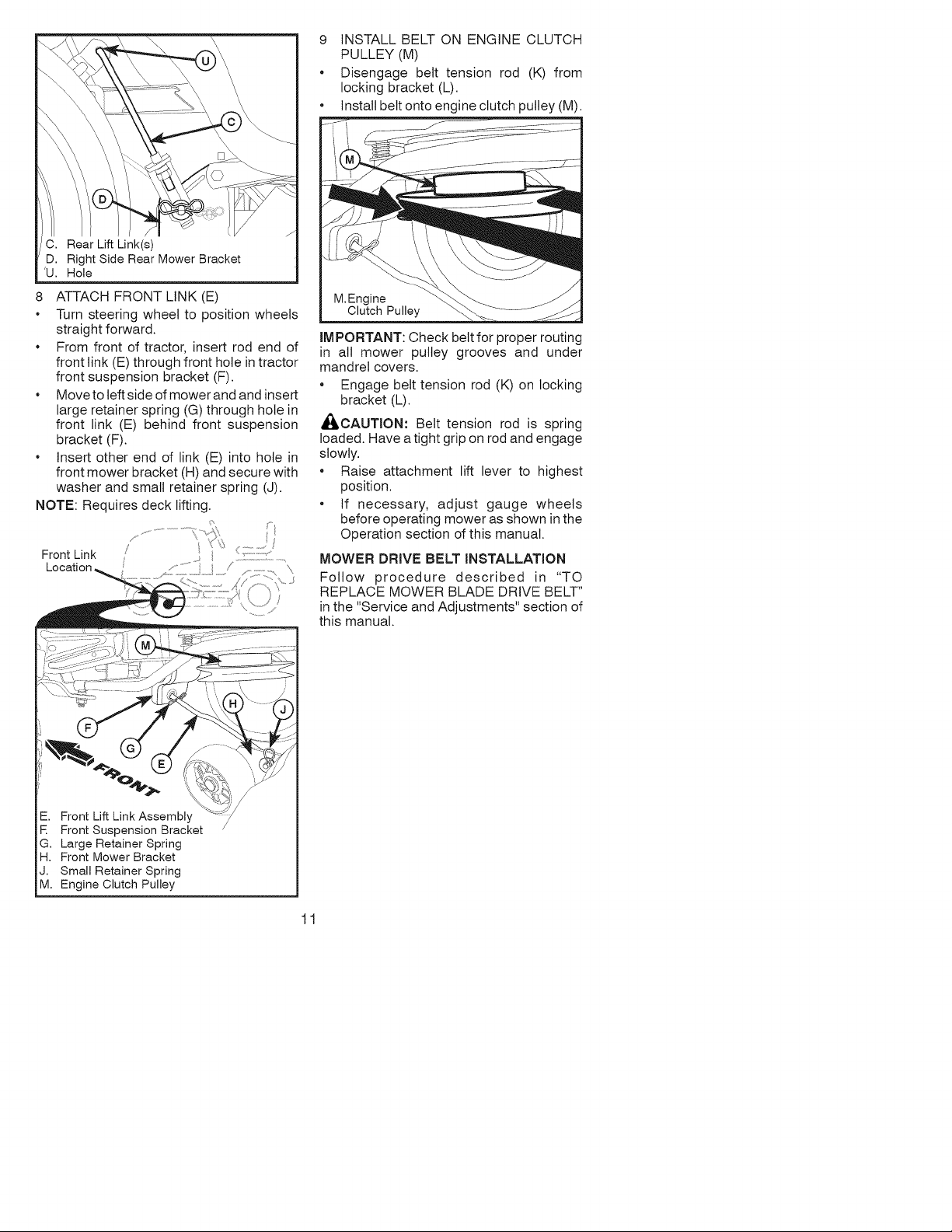
C. Rear Lift Link(s)
D. Right Side Rear Mower Bracket
'U. Hole
8 ATTACH FRONT LINK (E)
• Turn steering wheel to position wheels
straight forward.
• From front of tractor, insert rod end of
front link (E) through front hole in tractor
front suspension bracket (F).
• Moveto left side of mower and and insert
large retainer spring (G) through hole in
front link (E) behind front suspension
bracket (F).
• Insert other end of link (E) into hole in
front mower bracket (H) and secure with
washer and small retainer spring (J).
NOTE: Requires deck lifting.
........................... ¢
Front Link /
-. Front Lift Link Assembly
E Front Suspension Bracket
G. Large Retainer Spring
H. Front Mower Bracket
J. Small Retainer Spring
M. Engine Clutch Pulley
9 INSTALL BELT ON ENGINE CLUTCH
PULLEY (M)
• Disengage belt tension rod (K) from
locking bracket (L).
• Install belt onto engine clutch pulley (M).
M.Engine
Clutch Pulley
IMPORTANT: Check belt for proper routing
in all mower pulley grooves and under
mandrel covers.
• Engage belt tension rod (K) on locking
bracket (L).
_CAUTION" Belt tension rod is spring
loaded. Have a tight grip on rod and engage
slowly.
• Raise attachment lift lever to highest
position.
• If necessary, adjust gauge wheels
before operating mower as shown in the
Operation section of this manual.
MOWER DRIVE BELT iNSTALLATiON
Follow procedure described in "TO
REPLACE MOWER BLADE DRIVE BELT"
in the "Service and Adjustments" section of
this manual.
11
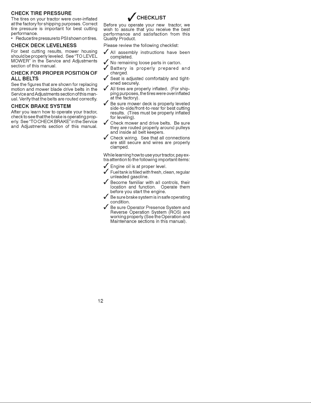
CHECK TIRE PRESSURE
The tires on your tractor were over-inflated
at the factory for shipping purposes. Correct
tire pressure is important for best cutting
performance.
Reducetire pressureto PSI shown on tires.
CHECK DECK LEVELNESS
For best cutting results, mower housing
should be properly leveled. See "TO LEVEL
MOWER" in the Service and Adjustments
section of this manual.
CHECK FOR PROPER POSITION OF
ALL BELTS
See the figures that are shown for replacing
motion and mower blade drive belts in the
Service and Adjustments section of this man-
ual. Verifythat the belts are routed correctly.
CHECK BRAKE SYSTEM
After you learn how to operate your tractor,
checkto see that the brake is operating prop-
erly. See "TO CH ECK BRAKE" inthe Service
and Adjustments section of this manual.
t#fCHECKLIST
Before you operate your new tractor, we
wish to assure that you receive the best
performance and satisfaction from this
Quality Product.
Please review the following checklist:
_" All assembly instructions have been
completed.
_" No remaining loose parts in carton.
J'Battery is properly prepared and
charged.
J" Seat is adjusted comfortably and tight-
ened securely.
J" All tires are properly inflated. (For ship-
ping purposes, the tires were overinftated
at the factory).
J" Be sure mower deck is properly leveled
side-to-side/front-to-rear for best cutting
results. (Tires must be properly inflated
for leveling).
J" Check mower and drive belts. Be sure
they are routed properly around pulleys
and inside all belt keepers.
J" Check wiring. See that all connections
are still secure and wires are properly
clamped.
While learning how to use your tractor, pay ex-
tra attention to the following important items:
J" Engine oil is at proper level.
J" Fuel tank is filled with fresh, clean, regular
unleaded gasoline.
J" Become familiar with all controls, their
location and function. Operate them
before you start the engine.
J" Be sure brake system is in safe operating
condition.
J" Be sure Operator Presence System and
Reverse Operation System (ROS) are
working properly (See the Operation and
Maintenance sections in this manual).
12
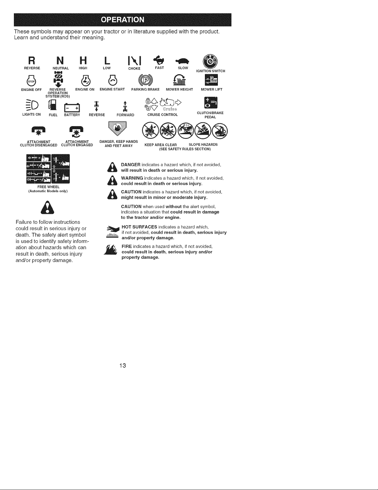
These symbols may appear on your tractor or in literature supplied with the product.
Learn and understand their meaning.
R N H
REVERSE NEUTRAL HIGH
I.I41
ENGINE OFF REVERSE ENGINE ON
OPERATION
SYSTEM(ROS)
LIGHTS ON FUEL BATTERY
ATTACHMENT ATTACHMENT
CLUTCH DISENGAGED CLUTCH ENGAGED
FREE WHEEL
(Automatic Models only)
Failure to follow instructions
could result in serious injury or
death. The safety alert symbol
is used to identify safety inform-
ation about hazards which can
result in death, serious injury
and/or property damage.
L IXl
LOW CHOKE FAST SLOW
0 (@)
ENGINE START PARKING BRAKE MOWER HEIGHT
iGNITION SWITCH
MOWER LIFT
REVERSE FORWARD CRUISE CONTROL
DANGER, KEEP HANDS
AND FEET AWAY
CLUTCH/BRAKE
PEDAL
®@@@@
KEEP AREA CLEAR SLOPE HAZARDS
(SEE SAFETY RULES SECTION)
DANGER indicates a hazard which, if not avoided,
will result in death or serious injury.
WARNING indicates a hazard which, if not avoided,
could result in death or serious injury.
CAUTION indicates a hazard which, if not avoided,
might result in minor or moderate injury.
CAUTION when used without the alert symbol,
indicates a situation that could result in damage
to the tractor and/or engine.
HOT SURFACES indicates a hazard which,
if not avoided, could result in death, serious injury
and/or property damage.
FIRE indicates a hazard which, if not avoided,
could result in death, serious injury and/or
property damage.
13
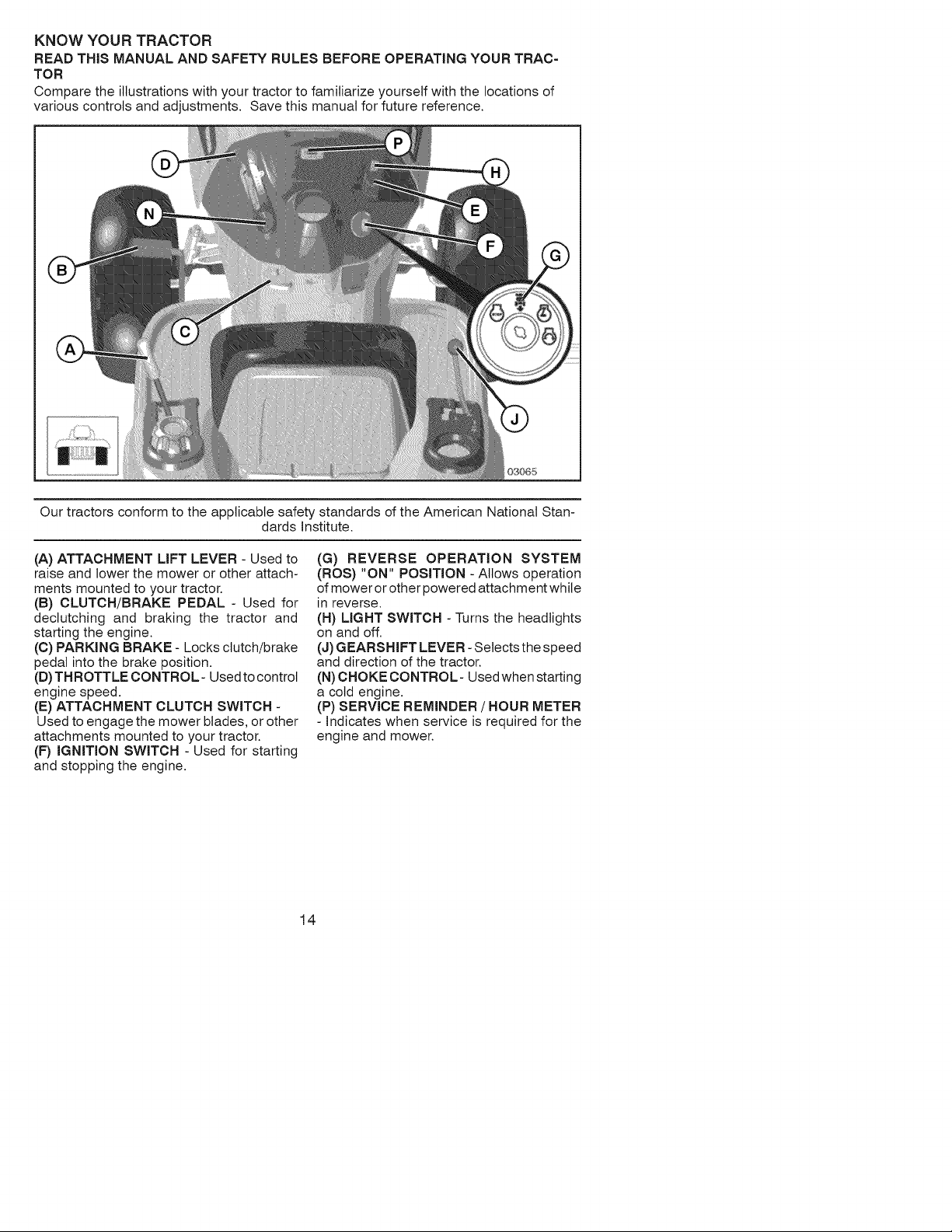
KNOW YOUR TRACTOR
READ THiS MANUAL AND SAFETY RULES BEFORE OPERATING YOUR TRAC-
TOR
Compare the illustrations with your tractor to familiarize yourself with the locations of
various controls and adjustments. Save this manual for future reference.
Our tractors conform to the applicable safety standards of the American National Stan-
dards Institute.
(A) ATTACHMENT LIFT LEVER - Used to
raise and lower the mower or other attach-
ments mounted to your tractor.
(B) CLUTCH/BRAKE PEDAL - Used for
declutching and braking the tractor and
starting the engine.
(C) PARKING BRAKE - Locks clutch/brake
pedal into the brake position.
(B) THROTTLE CONTROL- Used to control
engine speed.
(E) ATTACHMENT CLUTCH SWITCH -
Used to engage the mower blades, or other
attachments mounted to your tractor.
(F) iGNITiON SWITCH - Used for starting
and stopping the engine.
(G) REVERSE OPERATION SYSTEM
(ROS) "ON" POSITION - Allows operation
of mower or other powered attachment while
in reverse.
(H) LIGHT SWITCH - Turns the headlights
on and off.
(J) GEARSHIFT LEVER - Selects the speed
and direction of the tractor.
(N) CHOKE CONTROL- Used when starting
a cold engine.
(P) SERVICE REMINDER / HOUR METER
- Indicates when service is required for the
engine and mower.
14
Theoperationofanytractorcanresultinforeignobjectsthrownintothe
eyes,whichcanresultinsevereeyedamage.Alwayswearsafetyglasses
oreyeshieldswhileoperatingyourtractororperforminganyadjustments
orrepairs.Werecommendstandardsafetyglassesora widevisionsafety
maskwornoverspectacles.
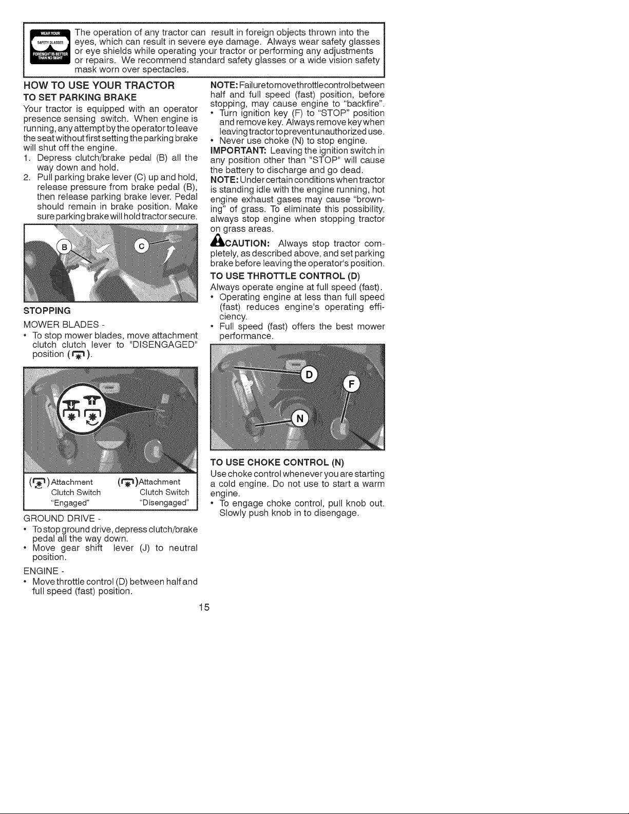
HOWTOUSEYOURTRACTOR
TOSET PARKING BRAKE
Your tractor is equipped with an operator
presence sensing switch. When engine is
running, any attempt bythe operator to leave
the seat without first setting the parking brake
will shut off the engine.
1. Depress clutch/brake pedal (B) all the
way down and hold.
2. Pull parking brake lever (C) up and hold,
release pressure from brake pedal (B),
then release parking brake lever. Pedal
should remain in brake position. Make
sure parking brake will hold tractor secure.
STOPPING
MOWER BLADES -
To stop mower blades, move attachment
clutch clutch lever to "DISENGAGED"
position (1"_).
NOTE: Failureto movethrottle controt between
half and full speed (fast) position, before
stopping, may cause engine to "backfire".
* Turn ignition key (F) to "STOP" position
and remove key. Always remove keywhen
leaving tractor to prevent unauthorized use.
. Never use choke (N) to stop engine.
iMPORTANT: Leaving the ignition switch in
any position other than "STOP" will cause
the battery to discharge and go dead.
NOTE: Under certain conditions when tractor
is standing idle with the engine running, hot
engine exhaust gases may cause "brown-
ing" of grass. To eliminate this possibility,
always stop engine when stopping tractor
on grass areas.
_ICAUTION: Always stop tractor com-
pletely, as described above, and set parking
brake before leaving the operator's position.
TO USE THROTTLE CONTROL (D)
Always operate engine at full speed (fast).
. Operating engine at less than full speed
(fast) reduces engine's operating effi-
ciency.
. Full speed (fast) offers the best mower
performance.
(1_1) Attachment (r_)Attachment
Clutch Switch Clutch Switch
"Engaged .... Disengaged"
GROUND DRIVE -
To stop ground drive, depress clutch/brake
pedal all the way down.
Move gear shift lever (J) to neutral
position.
ENGINE -
Move throttle control (D) between half and
full speed (fast) position.
TO USE CHOKE CONTROL (N)
Use choke control whenever you are starting
a cold engine. Do not use to start a warm
engine.
To engage choke control, pull knob out.
Slowly push knob in to disengage.
15
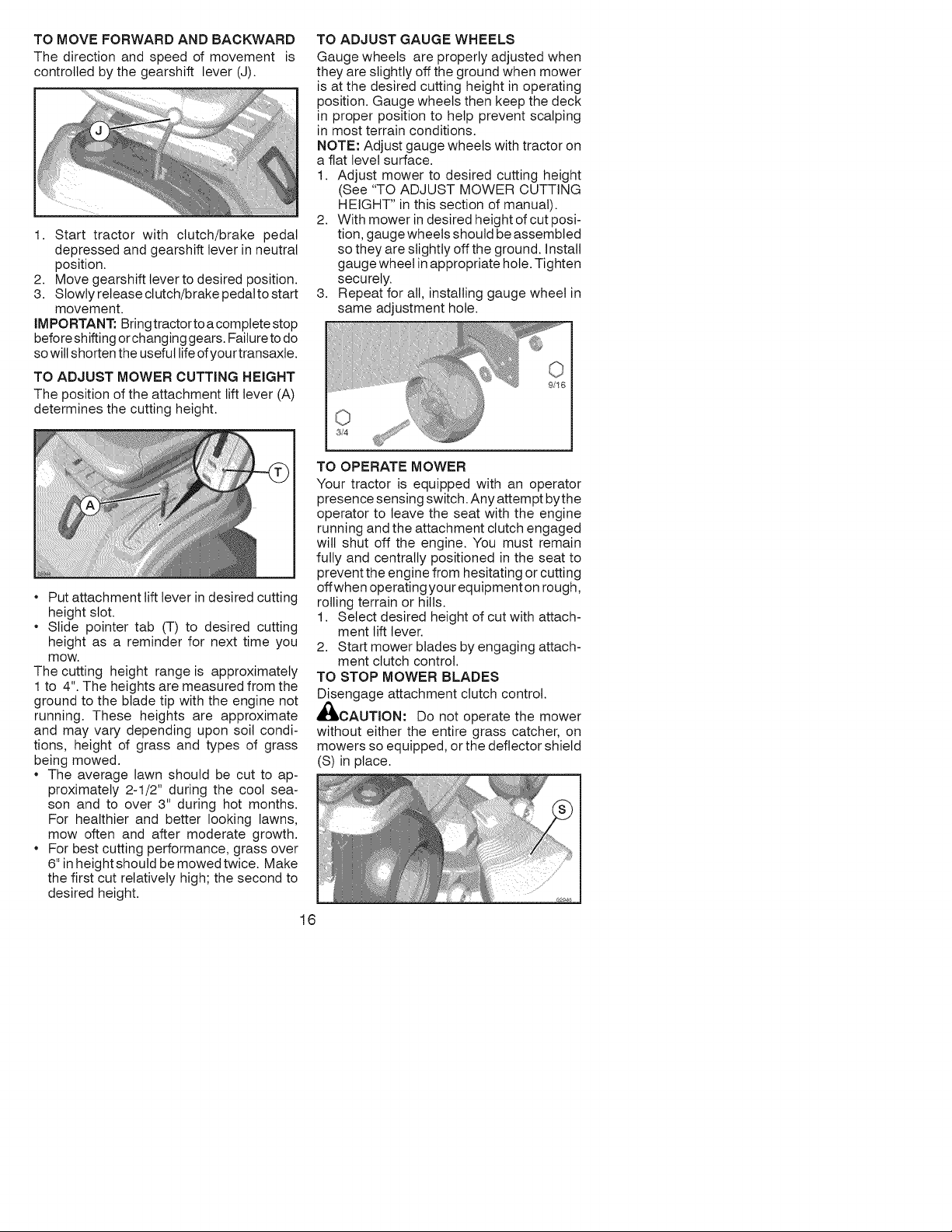
TOMOVE FORWARD AND BACKWARD
The direction and speed of movement is
controlled by the gearshift lever (J).
1. Start tractor with clutch/brake pedal
depressed and gearshift lever in neutral
position.
2. Move gearshift lever to desired position.
3. Slowly release clutch/brake pedal to start
movement.
IMPORTANT: Bring tractor to a complete stop
before shifting orchanging gears. Failure to do
so wilt shorten the useful life of your transaxte.
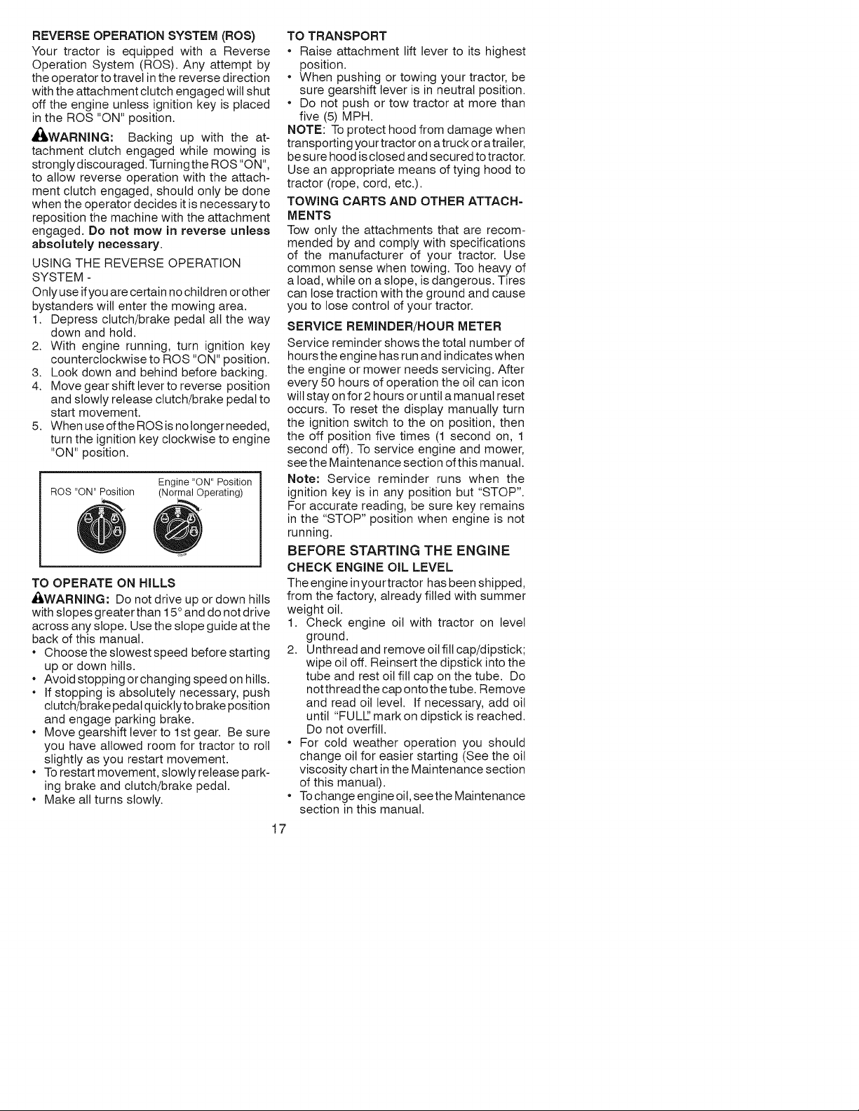
TO ADJUST MOWER CUTTING HEIGHT
The position of the attachment lift lever (A)
determines the cutting height.
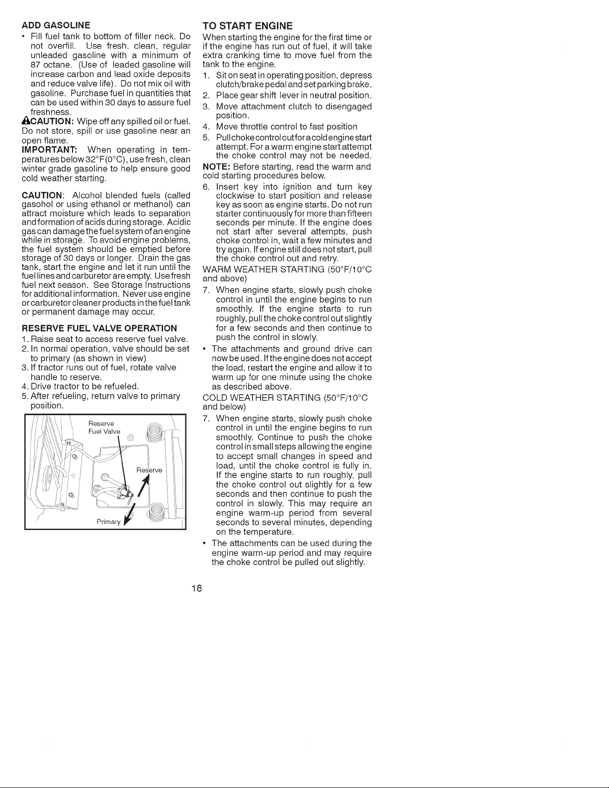
TO ADJUST GAUGE WHEELS
Gauge wheels are properly adjusted when
they are slightly off the ground when mower
is at the desired cutting height in operating
position. Gauge wheels then keep the deck
in proper position to help prevent scalping
in most terrain conditions.
NOTE: Adjust gauge wheels with tractor on
a flat level surface.
1. Adjust mower to desired cutting height
(See "TO ADJUST MOWER CUTTING
HEIGHT" in this section of manual).
2. With mower in desired height of cut posi-
tion, gauge wheels should be assembled
so they are slightly off the ground. Install
gauge wheel in appropriate hole. Tighten
securely.
3. Repeat for all, installing gauge wheel in
same adjustment hole.
Put attachment lift lever in desired cutting
height slot.
Slide pointer tab (T) to desired cutting
height as a reminder for next time you
mow.
The cutting height range is approximately
1 to 4". The heights are measured from the
ground to the blade tip with the engine not
running. These heights are approximate
and may vary depending upon soil condi-
tions, height of grass and types of grass
being mowed.
The average lawn should be cut to ap-
proximately 2-1/2" during the cool sea-
son and to over 3" during hot months.
For healthier and better looking lawns,
mow often and after moderate growth.
For best cutting performance, grass over
6" in height should be mowed twice. Make
the first cut relatively high; the second to
desired height.
16
TO OPERATE MOWER
Your tractor is equipped with an operator
presence sensing switch. Any attempt bythe
operator to leave the seat with the engine
running and the attachment clutch engaged
will shut off the engine. You must remain
fully and centrally positioned in the seat to
prevent the engine from hesitating or cutting
offwhen operating your equipment on rough,
rolling terrain or hills.
1. Select desired height of cut with attach-
ment lift lever.
2. Start mower blades by engaging attach-
ment clutch control.
TO STOP MOWER BLADES
Disengage attachment clutch control.
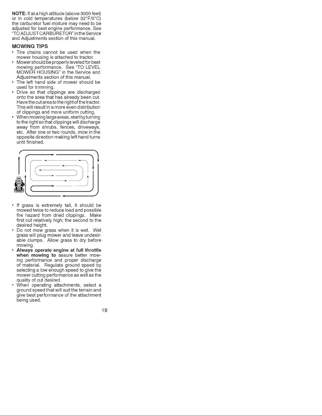
_IbCAUTION: Do not operate the mower
without either the entire grass catcher, on
mowers so equipped, or the deflector shield
(S) in place.
REVERSEOPERATIONSYSTEM (ROS)
Your tractor is equipped with a Reverse
Operation System (ROS). Any attempt by
the operator to travel in the reverse direction
with the attachment clutch engaged will shut
off the engine unless ignition key is placed
in the ROS "ON" position.
,_WARNING: Backing up with the at-
tachment clutch engaged while mowing is
strongly discouraged. Turning the ROS "ON",
to allow reverse operation with the attach-
ment clutch engaged, should only be done
when the operator decides it is necessary to
reposition the machine with the attachment
engaged. Do not mow in reverse unless
absolutely necessary.
USING THE REVERSE OPERATION
SYSTEM -
Only use if you are certain no children or other
bystanders will enter the mowing area.
1. Depress clutch/brake pedal all the way
down and hold.
2. With engine running, turn ignition key
counterclockwise to ROS "ON" position.
3. Look down and behind before backing.
4. Move gear shift lever to reverse position
and slowly release clutch/brake pedal to
start movement.
5. When use ofthe ROS is no longer needed,
turn the ignition key clockwise to engine
"ON" position.
ROS "ON" Position
Engine "ON" Position
(No1mal Operating)
TO OPERATE ON HILLS
_I,WARNING: Do not drive up or down hills
with slopes greater than 15° and do not drive
across any slope. Use the slope guide atthe
back of this manual.
• Choose the slowest speed before starting
up or down hills.
• Avoid stopping or changing speed on hills.
• If stopping is absolutely necessary, push
clutch/brake pedal quicktyto brake position
and engage parking brake.
• Move gearshift lever to 1st gear. Be sure
you have allowed room for tractor to roll
slightly as you restart movement.
• To restart movement, slowly release park-
ing brake and clutch/brake pedal.
• Make all turns slowly.
TO TRANSPORT
• Raise attachment lift lever to its highest
position.
• When pushing or towing your tractor, be
sure gearshift lever is in neutral position.
• Do not push or tow tractor at more than
five (5) MPH.
NOTE: To protect hood from damage when
transporting your tractor on a truck or a trailer,
be sure hood is closed and secured to tractor.
Use an appropriate means of tying hood to
tractor (rope, cord, etc.).
TOWING CARTS AND OTHER ATTACH-
MENTS
Tow only the attachments that are recom-
mended by and comply with specifications
of the manufacturer of your tractor. Use
common sense when towing. Too heavy of
a load, while on a slope, is dangerous. Tires
can lose traction with the ground and cause
you to lose control of your tractor.
SERVICE REMINDER/HOUR METER
Service reminder shows the total number of
hours the engine has run and indicates when
the engine or mower needs servicing. After
every 50 hours of operation the oil can icon
will stay on for 2 hours or until a manual reset
occurs. To reset the display manually turn
the ignition switch to the on position, then
the off position five times (1 second on, 1
second off). To service engine and mower,
see the Maintenance section of this manual.
Note: Service reminder runs when the
ignition key is in any position but "STOP".
For accurate reading, be sure key remains
in the "STOP" position when engine is not
running.
BEFORE STARTING THE ENGINE
CHECK ENGINE OIL LEVEL
The engine in your tractor has been shipped,
from the factory, already filled with summer
weight oil.
1. Check engine oil with tractor on level
ground.
2. Unthread and remove oil fill cap/dipstick;
wipe oil off. Reinsert the dipstick into the
tube and rest oil fill cap on the tube. Do
notthread the cap onto the tube. Remove
and read oil level. If necessary, add oil
until "FULL' mark on dipstick is reached.
Do not overfill.
• For cold weather operation you should
change oil for easier starting (See the oil
viscosity chart in the Maintenance section
of this manual).
• To change engine oil, seethe Maintenance
section in this manual.
17
ADDGASOLINE
* Fillfueltanktobottomoffillerneck.Do
notoverfill.Usefresh,clean,regular
unleadedgasolinewitha minimumof
87octane.(Useof leadedgasolinewill
increasecarbonandleadoxidedeposits
andreducevalvelife).Donotmixoilwith
gasoline.Purchasefuelinquantitiesthat
canbeusedwithin30daystoassurefuel
freshness.
AOAUTION:Wipeoffanyspilledoilorfuel.
Donotstore,spillorusegasolinenearan
openflame.
IMPORTANT:Whenoperatingin tem-
peraturesbelow32°F(0°C),usefresh,clean
wintergradegasolinetohelpensuregood
coldweatherstarting.
CAUTION:Alcoholblendedfuels(called
gasoholorusingethanolormethanol)can
attractmoisturewhichleadstoseparation
andformationofacidsduringstorage.Acidic
gascandamagethefuelsystemofanengine
whileinstorage.Toavoidengineproblems,
thefuelsystemshouldbeemptiedbefore
storageof30daysorlonger.Drainthegas
tank,starttheengineandletitrununtilthe
fuellinesandcarburetorareempty.Usefresh
fuelnextseason.SeeStorageInstructions
foradditionalinformation.Neveruseengine
orcarburetorcleanerproductsinthefueltank
orpermanentdamagemayoccur.
RESERVEFUELVALVEOPERATION
1.Raiseseattoaccessreservefuelvalve.
2.Innormaloperation,valveshouldbeset
toprimary(asshowninview)
3.Iftractorrunsoutoffuel,rotatevalve
handletoreserve.
4.Drivetractortoberefueled.
5.Afterrefueling,returnvalvetoprimary
position.
Reserve
Fuel Valve
Primary
TO START ENGINE
When starting the engine for the first time or
if the engine has run out of fuel, it will take
extra cranking time to move fuel from the
tank to the engine.
1. Siton seatin operating position, depress
clutch/brake pedal and set parking brake.
2. Place gearshift lever in neutral position.
3. Move attachment clutch to disengaged
position.
4. Move throttle control to fast position
5. Putl choke controt outfor a cotd engine start
attempt. For a warm engine start attempt
the choke control may not be needed.
NOTE: Before starting, read the warm and
cold starting procedures below.
6. Insert key into ignition and turn key
clockwise to start position and release
key as soon as engine starts. Do not run
starter continuously for more than fifteen
seconds per minute. If the engine does
not start after several attempts, push
choke control in, wait a few minutes and
try again. If engine still does not start, putt
the choke control out and retry.
WARM WEATHER STARTING (50°F/10°C
and above)
7. When engine starts, slowly push choke
control in until the engine begins to run
smoothly. If the engine starts to run
roughly, pull the choke control out slightly
for a few seconds and then continue to
push the control in slowly.
* The attachments and ground drive can
now be used. Ifthe engine does not accept
the load, restart the engine and allow it to
warm up for one minute using the choke
as described above.
COLD WEATHER STARTING (50°F/10°C
and below)
7. When engine starts, slowly push choke
control in until the engine begins to run
smoothly. Continue to push the choke
control in small steps allowing the engine
to accept small changes in speed and
load, until the choke control is fully in.
If the engine starts to run roughly, pull
the choke control out slightly for a few
seconds and then continue to push the
control in slowly. This may require an
engine warm-up period from several
seconds to several minutes, depending
on the temperature.
* The attachments can be used during the
engine warm-up period and may require
the choke control be pulled out slightly.
18
NOTE: If at a high altitude (above 3000 feet)
or in cold temperatures (below 32°F/0°C)
the carburetor fuel mixture may need to be
adjusted for best engine performance. See
"TO ADJUST CARBURETOR" in the Service
and Adjustments section of this manual.
MOWING TiPS
• Tire chains cannot be used when the
mower housing is attached to tractor.
• Mowershould be properly leveled for best
mowing performance. See "TO LEVEL
MOWER HOUSING" in the Service and
Adjustments section of this manual.
• The left hand side of mower should be
used for trimming.
• Drive so that clippings are discharged
onto the area that has already been cut.
Have the cut area to the right of the tractor.
This will result in a more even distribution
of clippings and more uniform cutting.
• When mowing large areas, start byturning
to the right so that clippings will discharge
away from shrubs, fences, driveways,
etc. After one or two rounds, mow in the
opposite direction making left hand turns
until finished.
-- <
• If grass is extremely tall, it should be
mowed twice to reduce load and possible
fire hazard from dried clippings. Make
first cut relatively high; the second to the
desired height.
• Do not mow grass when it is wet. Wet
grass will plug mower and leave undesir-
able clumps. Allow grass to dry before
mowing.
• Always operate engine at full throttle
when mowing to assure better mow-
ing performance and proper discharge
of material. Regulate ground speed by
selecting a low enough speed to give the
mower cutting performance as well as the
quality of cut desired.
• When operating attachments, select a
ground speed that will suit the terrain and
give best performance of the attachment
being used.
19
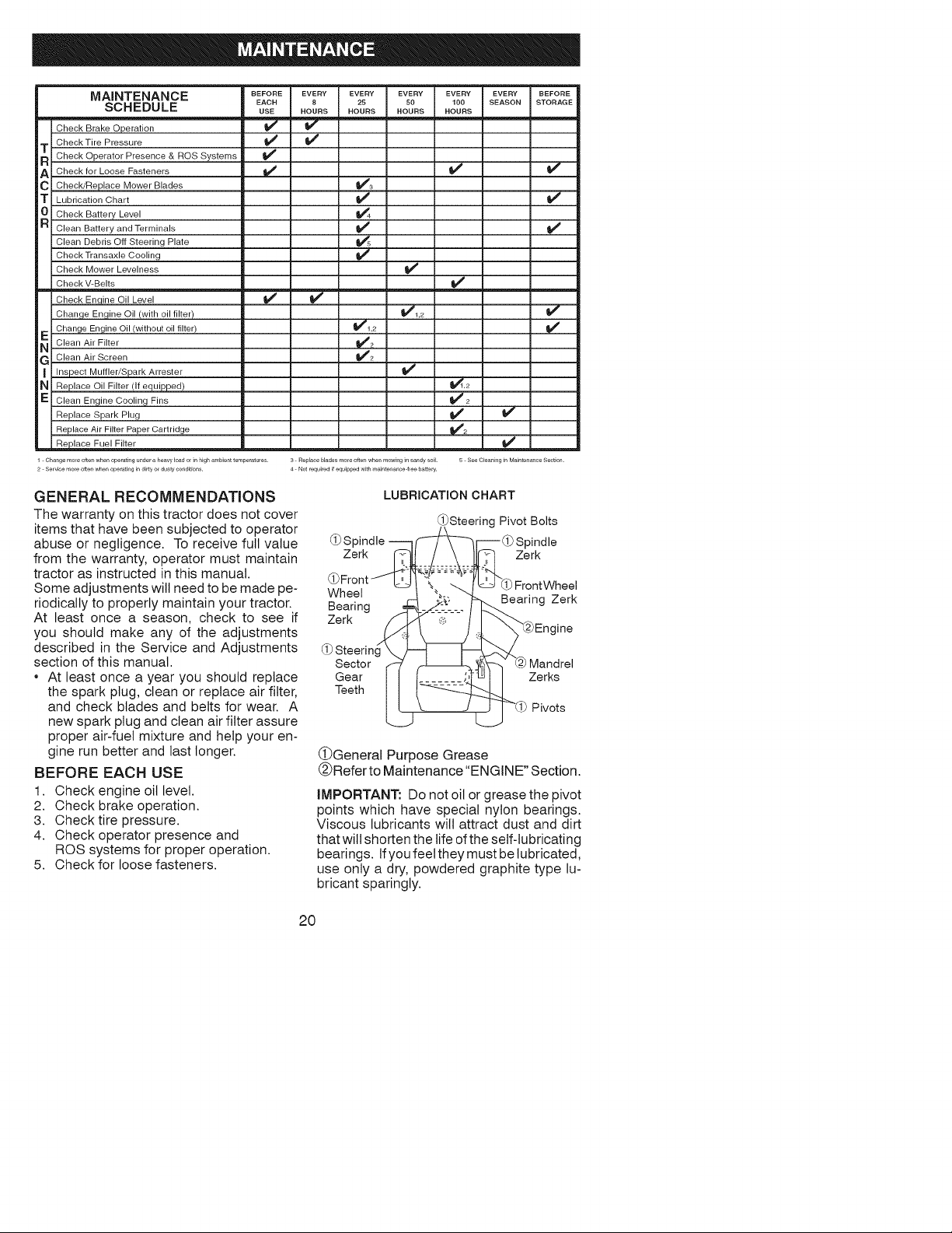
MAINTENANCE BEFOREEVERY EVERY
EACH 8 25
SCHEDULE USE HOURS HOURS
w
Check Brake Operation _
Check Tire Pressure
T Check Operator Presence & ROS Systems
A Check for Loose Fasteners
C Check/Replace Mower Blades _#'3
T Lubrication Chart
0 Check Battery Level !_4
R Clean Battery and Terminals
Clean Debris Off Steering Plate _s
Check Transaxle Cooling
Check Mower Levelness
Check V-Belts
Check Enqine Oil Level _
Change Engine Oil (with oil filter)
Change Engine Oil (without oil tilter) _1,2
E Clean Air Filter _2
G Clean Air Screen 1_2
Inspect Muffler/Spark Arrester
N Replace Oil Filter (If equipped)
E Clean Engine Cooling Fins
Replace Spark Plug
Replace Air Filter Paper Cartridge
__ R_lace Fuel Filter
EVERY EVERY EVERY BEFORE
SO 100 SEASON STORAGE
HOURS HOURS
v'
_i ,2
v'
v'
_2
V' v"
v'
v'
v'
1 Changemofeoftenwheno#eratingunderaheawloado[inhighambienttemperatures 3 Re_]Faoeb]adesmo[eoftenwhenmowinginsandysoil B SeeC_eaningJnMaintenanceSection
2 Se,v_cemo,eoft_wh_no_rat_g_ndJrlyo, du_ycondJt_ons 4 No_requ_red_f_qu_p_edw_thma_ntenance_,eebatt_rv
GENERAL RECOMMENDATIONS
The warranty on this tractor does not cover
items that have been subjected to operator
abuse or negligence. To receive full value
from the warranty, operator must maintain
tractor as instructed in this manual.
Some adjustments will need to be made pe-
riodically to properly maintain your tractor.
At least once a season, check to see if
you should make any of the adjustments
described in the Service and Adjustments
section of this manual.
• At least once a year you should replace
the spark plug, clean or replace air filter,
and check blades and belts for wear. A
new spark plug and clean air filter assure
proper air-fuel mixture and help your en-
gine run better and last longer.
BEFORE EACH USE
1. Check engine oil level.
2. Check brake operation.
3. Check tire pressure.
4. Check operator presence and
ROS systems for proper operation.
5. Check for loose fasteners.
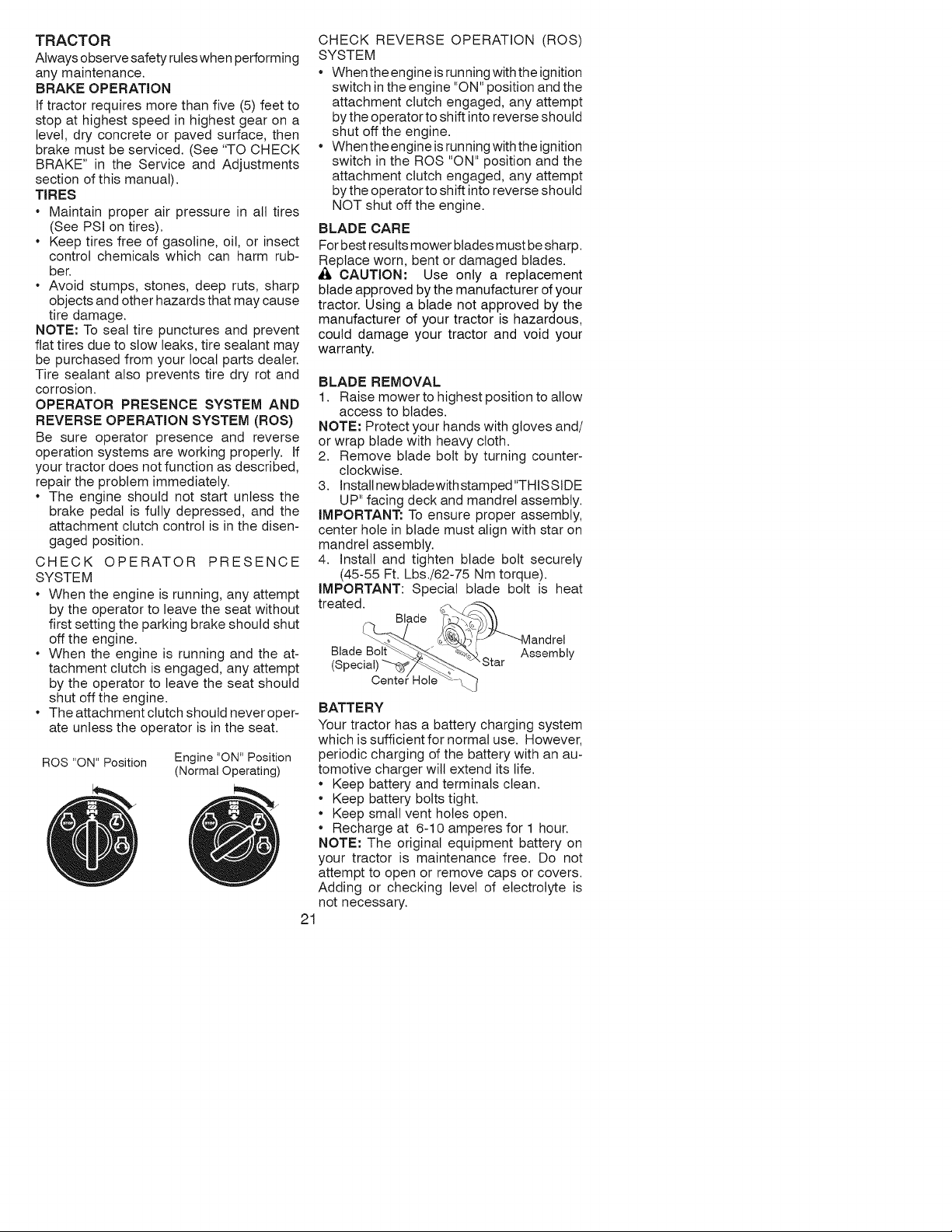
LUBRICATION CHART
_Steering Pivot Bolts
(_ Spindle ----q_r---(_ Spindle
Z erk _ -----_-_ _W._ Zerk
(_Front
, , ,J L_-_ "_..._. I_[_j--'(i)FrontWheel
vvneel /-_ _: _ Bearing Zerk
Zerk / l..R" ,_., t I _ ."--..___
/_ _ _..,L "_Q2)Eng ine
(_)Steering \ J---t _ 2_._
Sector r-- ' f-[_L_,_ _ Mandrel
Gear { t=- - - :::_'_ w i Zerks
Teeth I [ -_
L J__ _'(_) Pivots
(_General Purpose Grease
@Refer to Maintenance "ENGINE" Section.
IMPORTANT: Do not oil or grease the pivot
points which have special nylon bearings.
Viscous lubricants will attract dust and dirt
that will shorten the life of the self-lubricating
bearings. Ifyou feet they must be lubricated,
use only a dry, powdered graphite type lu-
bricant sparingly.
20
TRACTOR
Always observe safety rules when performing
any maintenance.
BRAKE OPERATION
If tractor requires more than five (5) feet to
stop at highest speed in highest gear on a
level, dry concrete or paved surface, then
brake must be serviced. (See "TO CHECK
BRAKE" in the Service and Adjustments
section of this manual).
TIRES
• Maintain proper air pressure in all tires
(See PSI on tires).
• Keep tires free of gasoline, oil, or insect
control chemicals which can harm rub-
bet.
• Avoid stumps, stones, deep ruts, sharp
objects and other hazards that may cause
tire damage.
NOTE: To seal tire punctures and prevent
flat tires due to slow leaks, tire sealant may
be purchased from your local parts dealer.
Tire sealant also prevents tire dry rot and
corrosion.
OPERATOR PRESENCE SYSTEM AND
REVERSE OPERATION SYSTEM (ROS)
Be sure operator presence and reverse
operation systems are working properly. If
your tractor does not function as described,
repair the problem immediately.
• The engine should not start unless the
brake pedal is fully depressed, and the
attachment clutch control is in the disen-
gaged position.
CHECK OPERATOR PRESENCE
SYSTEM
• When the engine is running, any attempt
by the operator to leave the seat without
first setting the parking brake should shut
off the engine.
• When the engine is running and the at-
tachment clutch is engaged, any attempt
by the operator to leave the seat should
shut off the engine.
• The attachment clutch should never oper-
ate unless the operator is in the seat.
ROS "ON" Position
Engine "ON" Position
(Normal Operating)
CHECK REVERSE OPERATION (ROS)
SYSTEM
When the engine is running with the ignition
switch in the engine "ON" position and the
attachment clutch engaged, any attempt
bythe operator to shift into reverse should
shut off the engine.
When the engine is running with the ignition
switch in the ROS "ON" position and the
attachment clutch engaged, any attempt
bythe operator to shift into reverse should
NOT shut off the engine.
BLADE CARE
For best results mower blades must be sharp.
Replace worn, bent or damaged blades.
A CAUTION: Use only a replacement
blade approved by the manufacturer of your
tractor. Using a blade not approved by the
manufacturer of your tractor is hazardous,
could damage your tractor and void your
warranty.
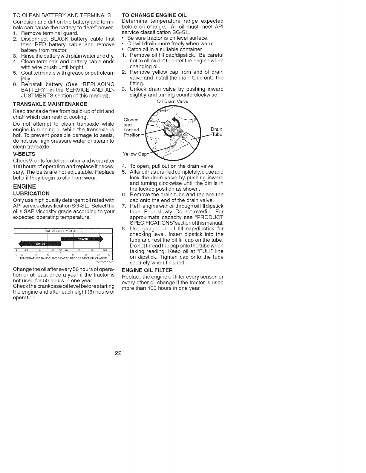
BLADE REMOVAL
1. Raise mower to highest position to allow
access to blades.
NOTE: Protect your hands with gloves and/
or wrap blade with heavy cloth.
2. Remove blade bolt by turning counter-
clockwise.
3. Install new bladewith stamped"THIS SIDE
UP" facing deck and mandrel assembly.
IMPORTANT: To ensure proper assembly,
center hole in blade must align with star on
mandrel assembly.
4. install and tighten blade bolt securely
(45-55 Ft. Lbs./62-75 Nm torque).
IMPORTANT: Special blade bolt is heat
treated.
Blade
Blade Assembly
"Star
Centel
BATTERY
Your tractor has a battery charging system
which is sufficient for normal use. However,
periodic charging of the battery with an au-
tomotive charger wilt extend its life.
• Keep battery and terminals clean.
• Keep battery bolts tight.
• Keep small vent holes open.
• Recharge at 6-10 amperes for 1 hour.
NOTE: The original equipment battery on
your tractor is maintenance free. Do not
attempt to open or remove caps or covers.
Adding or checking level of electrolyte is
not necessary.
21
TOCLEANBATTERYANDTERMINALS
Corrosionanddirtonthebatteryandtermi-
nalscancausethebatteryto"leak"power.
1. Removeterminalguard.
2. DisconnectBLACKbatterycablefirst
thenREDbatterycableandremove
batteryfromtractor.
3. Rinsethebatterywithplainwateranddry.
4. Cleanterminalsandbatterycableends
withwirebrushuntilbright.
5. Coatterminalswithgreaseorpetroleum
jelly.
6. Reinstallbattery(See"REPLACING
BATTERY"intheSERVICEANDAD-
JUSTMENTSsectionofthismanual).
TRANSAXLE MAINTENANCE
Keep transaxle free from build-up of dirt and
chaff which can restrict cooling.
Do not attempt to clean transaxle while
engine is running or while the transaxle is
hot. To prevent possible damage to seals,
do not use high pressure water or steam to
clean transaxle.
V-BELTS
Check V-belts for deterioration and wear after
100 hours of operation and replace if neces-
sary. The belts are not adjustable. Replace
belts if they begin to slip from wear.
ENGINE
LUBRiCATiON
Only use high quality detergent oil rated with
API service classification SG-SL Selectthe
oil's SAE viscosity grade according to your
expected operating temperature.
SAE VISCOSITY GRADES
_30 _20 q0 0 10 20 30 40
TEMPERATURE RANGE ANTICIPATED BEFORE NEXT OIL CHANGE
oil viscchart4e
Change the oil after every 50 hours of opera-
tion or at least once a year if the tractor is
not used for 50 hours in one year.
Checkthe crankcase oil level before starting
the engine and after each eight (8) hours of
operation.
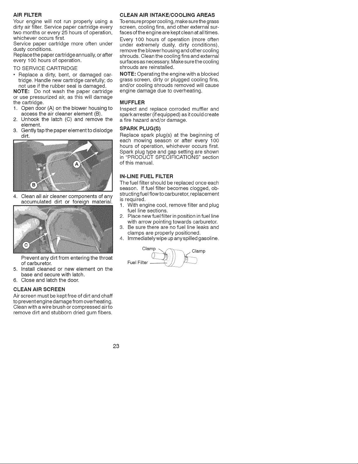
TO CHANGE ENGINE OiL
Determine temperature range expected
before oil change. All oil must meet API
service classification SG-SL
* Be sure tractor is on level surface.
* Oil will drain more freely when warm.
* Catch oil in a suitable container.
1. Remove oil fill cap/dipstick. Be careful
notto allow dirt to enter the engine when
changing oil.
Remove yellow cap from end of drain
valve and install the drain tube onto the
fitting.
Unlock drain valve by pushing inward
slightly and turning counterclockwise.
Oil DrainValve
2.
3.
Closed
and _ .-""
Locked L.
Position_ ",( -."
Yellow Oap_
4. To open, pull out on the drain valve.
5. After oil has drained completely, close and
lock the drain valve by pushing inward
and turning clockwise until the pin is in
the locked position as shown.
6. Remove the drain tube and replace the
cap onto the end of the drain valve.
7. Refill engine with oil through oil fill dipstick
tube. Pour slowly. Do not overfill. For
approximate capacity see "PRODUCT
SPECIFICATIONS"section of this manual.
8. Use gauge on oil fill cap/dipstick for
checking level. Insert dipstick into the
tube and rest the oil fill cap on the tube.
Do not thread the cap onto the tube when
taking reading. Keep oil at "FULL' line
on dipstick. Tighten cap onto the tube
securely when finished.
ENGINE OiL FILTER
Replace the engine oil filter every season or
every other oil change if the tractor is used
more than 100 hours in one year.
22
AiR FILTER
Your engine will not run properly using a
dirty air filter. Service paper cartridge every
two months or every 25 hours of operation,
whichever occurs first.
Service paper cartridge more often under
dusty conditions.
Replace the paper cartridge annually, or after
every 100 hours of operation.
TO SERVICE CARTRIDGE
Replace a dirty, bent, or damaged car-
tridge. Handle new cartridge carefully; do
not use if the rubber seat is damaged.
NOTE: Do not wash the paper cartridge
or use pressurized air, as this will damage
the cartridge.
1. Open door (A) on the blower housing to
access the air cleaner element (B).
2. Unhook the latch (C) and remove the
element.
3. Gently tap the paper element to dislodge
dirt.
4. Clean all air cleaner components of any
accumulated dirt or foreign material.
Prevent any dirt from entering the throat
of carburetor.
5. Install cleaned or new element on the
base and secure with latch.
6. Close and latch the door.
CLEAN AIR SCREEN
Air screen must be kept free of dirt and chaff
to prevent engine damage from overheating.
Clean with a wire brush or compressed airto
remove dirt and stubborn dried gum fibers.
CLEAN AiR INTAKE/COOLING AREAS
To ensure proper cooling, make sure the grass
screen, cooling fins, and other external sur-
faces of the engine are kept ctean at all times.
Every 100 hours of operation (more often
under extremely dusty, dirty conditions),
remove the blower housing and other cooling
shrouds. Clean the cooling fins and external
surfaces as necessary. Make sure the cooling
shrouds are reinstalled.
NOTE: Operating the engine with a blocked
grass screen, dirty or plugged cooling fins,
and/or cooling shrouds removed wilt cause
engine damage due to overheating.
MUFFLER
inspect and replace corroded muffler and
spark arrester (if equipped) as it could create
a fire hazard and/or damage.
SPARK PLUG(S)
Replace spark plug(s) at the beginning of
each mowing season or after every 100
hours of operation, whichever occurs first.
Spark plug type and gap setting are shown
in "PRODUCT SPECIFICATIONS" section
of this manual.
IN=LINE FUEL FILTER
The fuel filter should be replaced once each
season. If fuel filter becomes clogged, ob-
structing fuel flow to carburetor, replacement
is required.
1. With engine cool, remove filter and plug
fuel line sections.
2. Place new fuelfilter in position in fuel line
with arrow pointing towards carburetor.
3. Be sure there are no fuel line leaks and
clamps are properly positioned.
4. Immediatetywipe up anyspilled gasoline.
Clamp _ __ Clamp
Fuel Filter ___ _L'-I
23
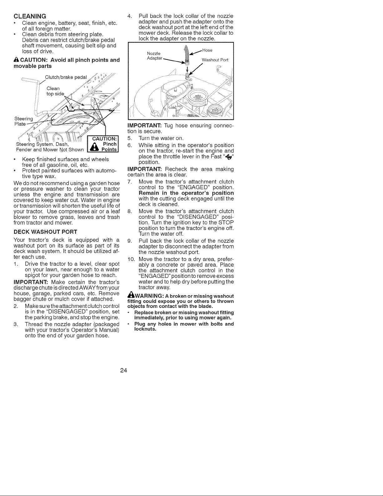
CLEANING
• Clean engine, battery, seat, finish, etc.
of all foreign matter.
• Clean debris from steering plate.
Debris can restrict clutch/brake pedal
shaft movement, causing belt slip and
loss of drive.
A CAUTION: Avoid all pinch points and
movable parts
Clutch/brake pedal
Clean
top side
Steering
CAUTION:
\
Steering System, Dash, & Pinch
Fender and Mower Not Shown Points
• Keep finished surfaces and wheels
free of all gasoline, oil, etc.
• Protect painted surfaces with automo-
tive type wax.
We do not recommend using a garden hose
or pressure washer to clean your tractor
unless the engine and transmission are
covered to keep water out. Water in engine
or transmission will shorten the useful life of
your tractor. Use compressed air or a leaf
blower to remove grass, leaves and trash
from tractor and mower.
DECK WASHOUT PORT
Your tractor's deck is equipped with a
washout port on its surface as part of its
deck wash system. It should be utilized af-
ter each use.
1. Drive the tractor to a level, clear spot
on your lawn, near enough to a water
spigot for your garden hose to reach.
iMPORTANT: Make certain the tractor's
discharge chute is directed AWAY from your
house, garage, parked cars, etc. Remove
bagger chute or mulch cover if attached.
2. Make sure the attachment clutch controt
is in the "DISENGAGED" position, set
the parking brake, and stop the engine.
3. Thread the nozzle adapter (packaged
with your tractor's Operator's Manual)
onto the end of your garden hose.
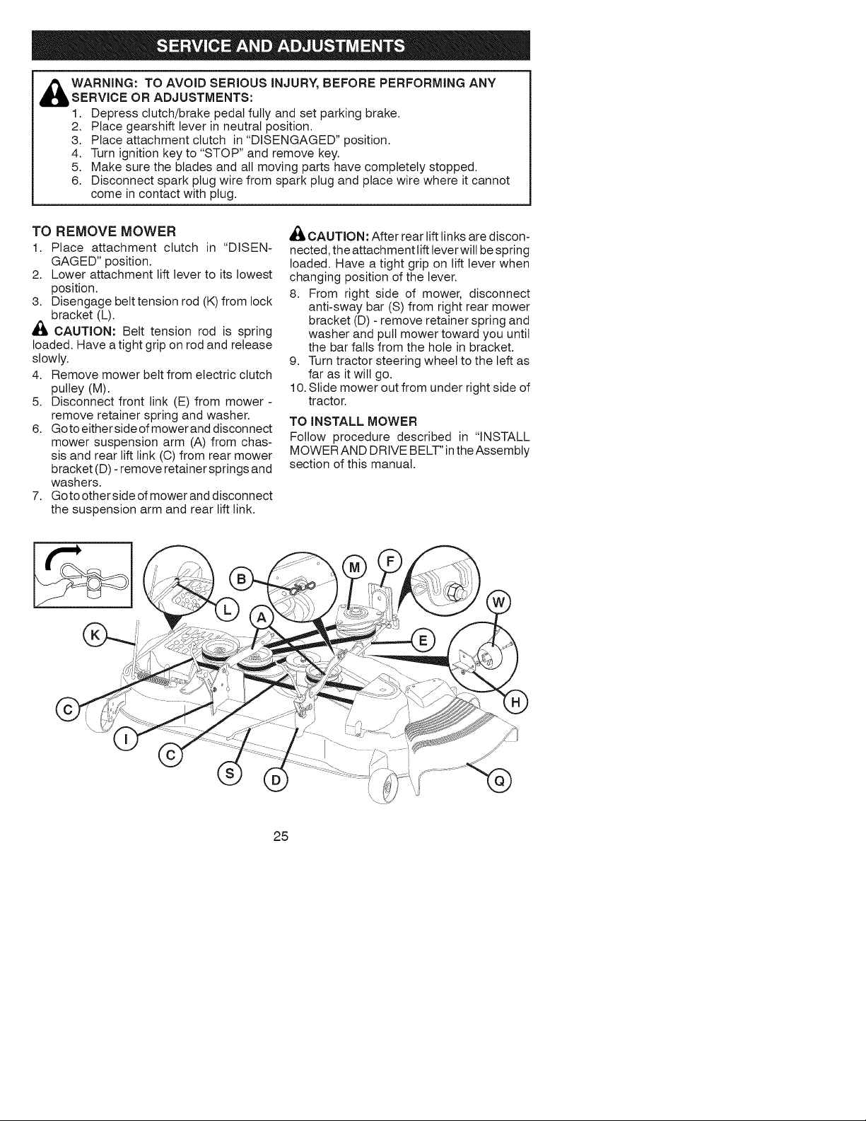
4, Pull back the lock collar of the nozzle
adapter and push the adapter onto the
deck washout port at the left end of the
mower deck. Release the lock collar to
lock the adapter on the nozzle.
Nozzle
Ads
Washout Port
iMPORTANT: Tug hose ensuring connec-
tion is secure.
5. Turn the water on.
6. While sitting in the operator's position
on the tractor, re-start the engine and
place the throttle lever in the Fast "_"
position.
iMPORTANT: Recheck the area making
certain the area is clear.
7. Move the tractor's attachment clutch
control to the "ENGAGED" position.
Remain in the operator's position
with the cutting deck engaged until the
deck is cleaned.
8. Move the tractor's attachment clutch
control to the "DISENGAGED" posi-
tion. Turn the ignition key to the STOP
position to turn the tractor's engine off.
Turn the water off.
9. Pull back the lock collar of the nozzle
adapter to disconnect the adapter from
the nozzle washout port.
10. Move the tractor to a dry area, prefer-
ably a concrete or paved area. Place
the attachment clutch control in the
"ENGAGED" position to remove excess
water and to help dry before putting the
tractor away.
_WARNING: A broken or missing washout
fitting could expose you or others to thrown
objects from contact with the blade.
Replace broken or missing washout fitting
immediately, prior to using mower again.
Plug any holes in mower with bolts and
Ioeknuts,
24
WARNING: TO AVOID SERIOUS iNJURY, BEFORE PERFORMING ANY
SERVICE OR ADJUSTMENTS:
1. Depress clutch/brake pedal fully and set parking brake.
2. Place gearshift lever in neutral position.
3. Place attachment clutch in "DISENGAGED" position.
4. Turn ignition key to "STOP" and remove key.
5. Make sure the blades and all moving parts have completely stopped.
6. Disconnect spark plug wire from spark plug and place wire where it cannot
come in contact with plug.
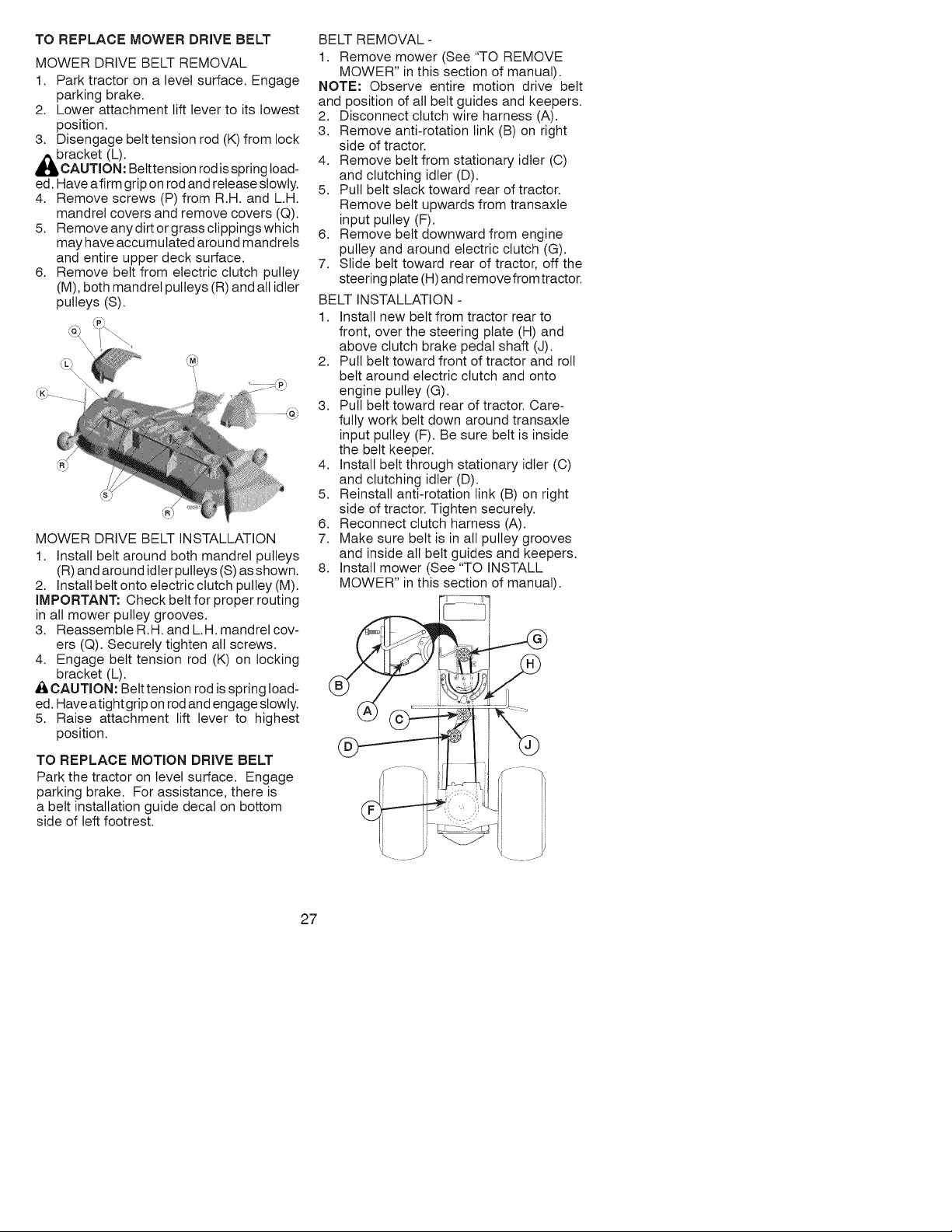
TO REMOVE MOWER
1. Place attachment clutch in "DISEN-
GAGED" position.
2. Lower attachment lift lever to its lowest
position.
3. Disengage belt tension rod (K) from lock
bracket (L).
CAUTION: Belt tension rod is spring
loaded. Have a tight grip on rod and release
slowly.
4. Remove mower belt from electric clutch
pulley (M).
5. Disconnect front link (E) from mower -
remove retainer spring and washer.
6. Goto eitherside of mowerand disconnect
mower suspension arm (A) from chas-
sis and rear lift link (O) from rear mower
bracket (D) - remove retainer springs and
washers.
7. Goto otherside of mower and disconnect
the suspension arm and rear lift link.
_, CAUTION: After rear lift links are discon-
nected, the attachment lift lever will be spring
loaded. Have a tight grip on lift lever when
changing position of the lever.
8. From right side of mower, disconnect
anti-sway bar (S) from right rear mower
bracket (D) - remove retainer spring and
washer and pull mower toward you until
the bar falls from the hole in bracket.
9. Turn tractor steering wheel to the left as
far as it will go.
10. Slide mower out from under right side of
tractor.
TO iNSTALL MOWER
Follow procedure described in "INSTALL
MOWER AND DRIVE BELT" inthe Assembly
section of this manual.
25

TO LEVEL MOWER
Make sure tires are properly inflated to the
PSI shown on tires. If tires are over or under
inflated, it may affect the appearance of your
lawn and lead you to think the mower is not
adjusted properly.
VISUAL SIDE-TO-SIDE ADJUSTMENT
1. With all tires properly inflated and if your
lawn appears unevenly cut, determine
which side of mower is cutting lower.
NOTE: As desired, you can raise the low
side of mower or lower the high side.
2. Go to side of mower you wish to adjust.
3. With a 3/4" or adjustable wrench, turn
lift link adjustment nut (A) to the left to
lower the mower or, to the right to raise
the mower.
)
Turn nut ric Turn nut left
to raise mower to lower mower
NOTE: Each full turn of adjustment nut will
change mower height about 3/16".
4. Test your adjustment by mowing some
uncut grass and visually checking the
appearance. Readjust, if necessary, until
you are satisfied with the results.
PRECISION SIDE-TO-SIDE ADJUSTMENT
1. With all tires properly inflated, park tractor
on level ground or driveway.
CAUTION: Blades are sharp. Protect
your hands with gloves and/or wrap blade
with heavy cloth.
2. Raise mower to its highest position.
3. At both sides of mower, position blade at
side and measure the distance (A) from
bottom edge of blade to the ground. The
distanceshoutd bethesame on both sides.
AI ::: ::z .... ::::::::: IA
4. If adjustment is necessary, see steps 2
and 3 in Visual Adjustment instructions
above.
5. Recheckmeasurements, adjustifneces-
sary until both sides are equal.
FRONT-TO-BACK ADJUSTMENT
iMPORTANT: Deck must be level side-
to-side.
To obtain the best cutting results, the mower
blades should be adjusted so the front tip is
1/8" to 1/2" lower than the rear tip when the
mower is in its highest position.
CAUTION: Blades are sharp. Protect
your hands with gloves and/or wrap blade
with heavy cloth.
• Raise mower to highest position.
• Position any blade so the tip is pointing
straight forward. Measure distance (B) to
the ground at front and rear tip of the blade.
26
• If front tip of blade is not 1/8" to 1/2" lower
than the rear tip, go to the front of tractor.
• With an 11/16" or adjustable wrench,
loosen jam nut A several turns to clear
adjustment nut B.
• With a 3/4" or adjustable wrench, turn
front link adjustment nut (B) clockwise
(ltighten) to raise the front of mower, or,
counterclockwise (loosen) to lower the
front mower.
Tighten adjust nut Loosen adjust
B to raise mower nut B to lower
mower
Loosen jam nutA first
NOTE: Each full turn of the adjustment nut
will change mower height about 1/8".
• Recheck measurements, adjust if neces-
sary until front tip of blade is 1/8" to 1/2"
lower than the rear tip.
• Hold adjustment nut in position with wrench
and tighten jam nut securely against ad-
justment nut.
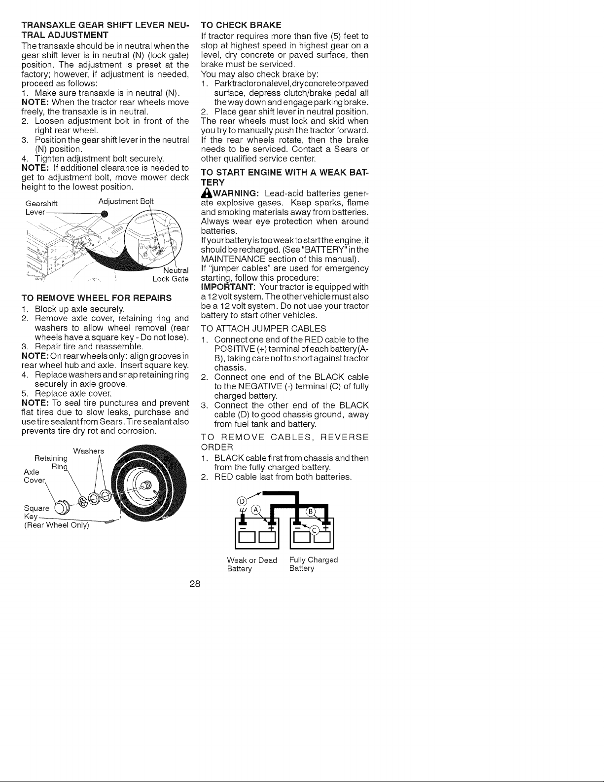
TO REPLACE MOWER DRIVE BELT
MOWER DRIVE BELT REMOVAL
1. Park tractor on a level surface. Engage
parking brake.
2. Lower attachment lift lever to its lowest
position.
3. Disengage betttension rod (K) from lock
bracket (L).
AUTION: Betttension rod is spring load-
ed. Have afirm grip on rod and release slowly.
4. Remove screws (P) from R.H. and L.H.
mandrel covers and remove covers (Q).
5. Remove any dirt or grass clippings which
may have accumulated around mandrels
and entire upper deck surface.
6. Remove belt from electric clutch pulley
(M), both mandrel pulleys (R) and all idler
pulleys (S).
MOWER DRIVE BELT INSTALLATION
1. Install belt around both mandrel pulleys
(R) and around idler pulleys (S) as shown.
2. Install belt onto electric clutch pulley (M).
iMPORTANT: Check belt for proper routing
in all mower pulley grooves.
3. Reassemble R.H. and L.H. mandrel cov-
ers (Q). Securely tighten all screws.
4. Engage belt tension rod (K) on locking
bracket (L).
,A CAUTION: Belt tension rod is spring load-
ed. Have atight grip on rod and engage slowly.
5. Raise attachment lift lever to highest
position.
TO REPLACE MOTION DRIVE BELT
Park the tractor on level surface. Engage
parking brake. For assistance, there is
a belt installation guide decal on bottom
side of left footrest.
BELT REMOVAL -
1. Remove mower (See "TO REMOVE
MOWER" in this section of manual).
NOTE: Observe entire motion drive belt
and position of all belt guides and keepers.
2. Disconnect clutch wire harness (A).
3. Remove anti-rotation link (B) on right
side of tractor.
4. Remove belt from stationary idler (C)
and clutching idler (D).
5. Pull belt slack toward rear of tractor.
Remove belt upwards from transaxle
input pulley (F).
6. Remove belt downward from engine
pulley and around electric clutch (G).
7. Slide belt toward rear of tractor, off the
steering plate (H) and remove from tractor.
BELT INSTALLATION -
1. Install new belt from tractor rear to
front, over the steering plate (H) and
above clutch brake pedal shaft (J).
2. Pull belt toward front of tractor and roll
belt around electric clutch and onto
engine pulley (G).
3. Putt belt toward rear of tractor. Care-
fully work belt down around transaxle
input pulley (F). Be sure belt is inside
the belt keeper.
4. Install belt through stationary idler (C)
and clutching idler (D).
5. Reinstall anti-rotation link (B) on right
side of tractor. Tighten securely.
6. Reconnect clutch harness (A).
7. Make sure belt is in all pulley grooves
and inside all belt guides and keepers.
8. Install mower (See "TO INSTALL
MOWER" in this section of manual).
27
TRANSAXLE GEAR SHIFT LEVER NEU-
TRAL ADJUSTMENT
The transaxte should be in neutral when the
gear shift lever is in neutral (N) (lock gate)
position. The adjustment is preset at the
factory; however, if adjustment is needed,
proceed as follows:
1. Make sure transaxle is in neutral (N).
NOTE: When the tractor rear wheels move
freely, the transaxle is in neutral.
2. Loosen adjustment bolt in front of the
right rear wheel.
3. Position the gear shift lever in the neutral
(N) position.
4. Tighten adjustment bolt securely.
NOTE: If additional clearance is needed to
get to adjustment bolt, move mower deck
height to the lowest position.
Gearshift Adjustment Bolt
Lever
Lock Gate
TO REMOVE WHEEL FOR REPAIRS
1. Block up axle securely.
2. Remove axle cover, retaining ring and
washers to allow wheel removal (rear
wheels have a square key - Do not lose).
3. Repair tire and reassemble.
NOTE: On rear wheels only: align grooves in
rear wheel hub and axle. Insert square key.
4. Replace washers and snap retaining ring
securely in axle groove.
5. Replace axle cover.
NOTE: To seat tire punctures and prevent
flat tires due to stow leaks, purchase and
use tire sealant from Sears. Tire sealant also
prevents tire dry rot and corrosion.
Washers
Retaining
Axl e
Cover_
Square
Key_ ,
(Rear Wheel Only)
TO CHECK BRAKE
if tractor requires more than five (5) feet to
stop at highest speed in highest gear on a
level, dry concrete or paved surface, then
brake must be serviced.
You may also check brake by:
1. Parktractoronalevel, dryconcreteorpaved
surface, depress clutch/brake pedal all
the way down and engage parking brake.
2. Place gear shift lever in neutral position.
The rear wheels must lock and skid when
you try to manually push the tractor forward.
If the rear wheels rotate, then the brake
needs to be serviced. Contact a Sears or
other qualified service center.
TO START ENGINE WITH A WEAK BAT-
TERY
_WARNING: Lead-acid batteries gener-
ate explosive gases. Keep sparks, flame
and smoking materials away from batteries.
Always wear eye protection when around
batteries.
Ifyou r battery is too weak to start the en gin e, it
should be recharged. (See "BATTERY" in the
MAINTENANCE section of this manual).
If "jumper cables" are used for emergency
starting, follow this procedure:
IMPORTANT: Your tractor is equipped with
a 12 volt system. The othervehicte must atso
be a 12 volt system. Do not use your tractor
battery to start other vehicles.
TO ATTACH JUMPER CABLES
1. Connect one end of the RED cable to the
POSITIVE (+)terminal of each battery(A-
B), taking care not to short against tractor
chassis.
2. Connect one end of the BLACK cable
to the NEGATIVE (-) terminal (C) of fully
charged battery.
3. Connect the other end of the BLACK
cable (D) to good chassis ground, away
from fuel tank and battery.
TO REMOVE CABLES, REVERSE
ORDER
1. BLACK cable first from chassis and then
from the fully charged battery.
2. RED cable last from both batteries.
28
Weak or Dead Fully Charged
Battery Battery
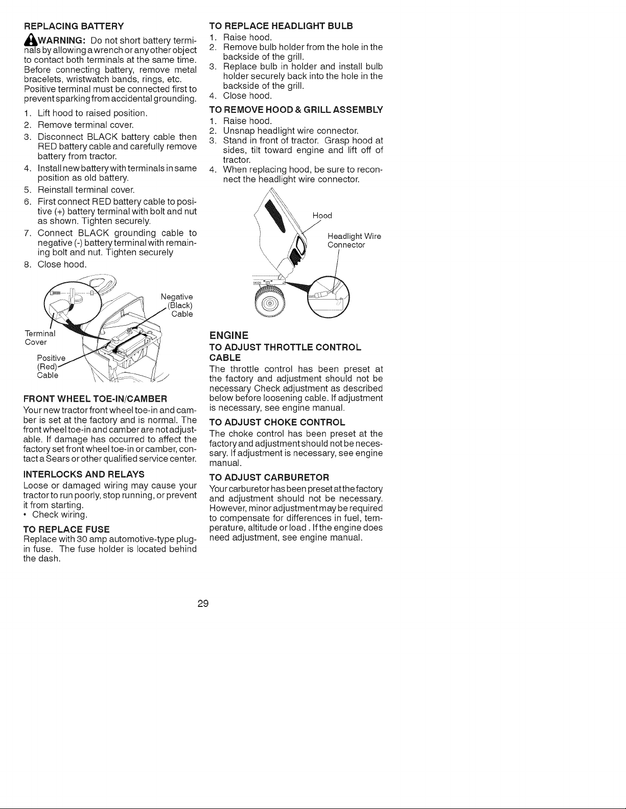
REPLACING BATTERY
WARNING: Do not short battery termi-
nals by allowing a wrench or any other object
to contact both terminals at the same time.
Before connecting battery, remove metal
bracelets, wristwatch bands, rings, etc.
Positive terminal must be connected first to
prevent sparking from accidental grounding.
1. Lift hood to raised position.
2. Remove terminal cover.
3. Disconnect BLACK battery cable then
RED battery cable and carefully remove
battery from tractor.
4. Install new battery with terminals in same
position as old battery.
5. Reinstall terminal cover.
6. First connect RED battery cable to posi-
tive (+) battery terminal with bolt and nut
as shown. Tighten securely.
7. Connect BLACK grounding cable to
negative (-) battery terminal with remain-
ing bolt and nut. Tighten securely
8. Close hood.
FRONT WHEEL TOE=IN/CAMBER
Your new tractor front wheel toe-in and cam-
ber is set at the factory and is normal. The
front wheel toe-in and camber are not adjust-
able. If damage has occurred to affect the
factory set front wheel toe-in or camber, con-
tact a Sears or other qualified service center.
INTERLOCKS AND RELAYS
Loose or damaged wiring may cause your
tractor to run poorly, stop running, or prevent
it from starting.
• Check wiring.
TO REPLACE FUSE
Replace with 30 amp automotive-type plug-
in fuse. The fuse holder is located behind
the dash.
TO REPLACE HEADLIGHT BULB
1. Raise hood.
2. Remove bulb holder from the hole in the
backside of the grill.
3. Replace bulb in holder and install bulb
holder securely back into the hole in the
backside of the grill.
4. Close hood.
TO REMOVE HOOD & GRILL ASSEMBLY
1. Raise hood.
2. Unsnap headlight wire connector.
3. Stand in front of tractor. Grasp hood at
sides, tilt toward engine and lift off of
tractor.
4. When replacing hood, be sure to recon-
nect the headlight wire connector.
Hood
Headlight Wire
Connector
ENGINE
TO ADJUST THROTTLE CONTROL
CABLE
The throttle control has been preset at
the factory and adjustment should not be
necessary Check adjustment as described
below before loosening cable. If adjustment
is necessary, see engine manual.
TO ADJUST CHOKE CONTROL
The choke control has been preset at the
factory and adjustment should not be neces-
sary. If adjustment is necessary, see engine
manual.
TO ADJUST CARBURETOR
Your carburetor has been preset atth e factory
and adjustment should not be necessary.
However, minor adjustment may be required
to compensate for differences in fuel, tem-
perature, altitude or load. If the engine does
need adjustment, see engine manual.
29
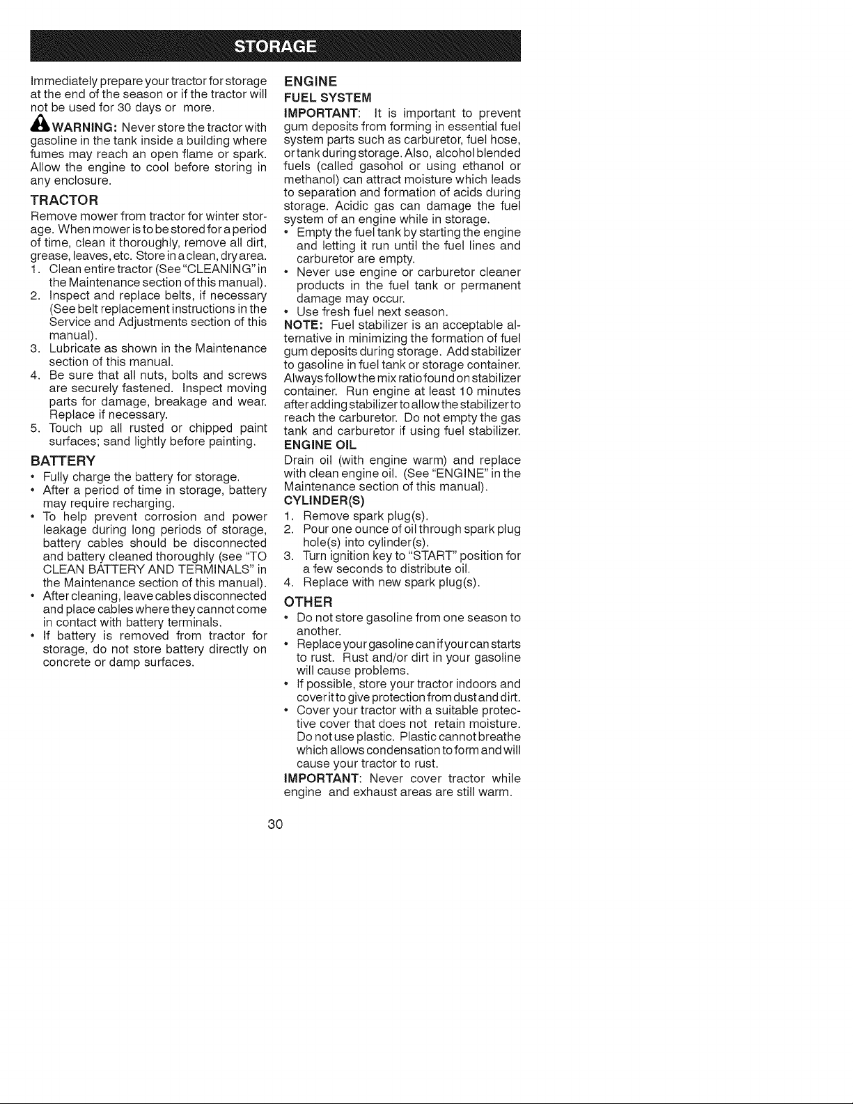
Immediately prepare your tractor for storage
at the end of the season or if the tractor will
not be used for 30 days or more.
WARNING: Never store the tractor with
gasoline in the tank inside a building where
fumes may reach an open flame or spark.
Allow the engine to cool before storing in
any enclosure.
TRACTOR
Remove mower from tractor for winter stor-
age. When mower is to be stored for a period
of time, clean it thoroughly, remove all dirt,
grease, leaves, etc. Store ina clean, dry area.
1. Clean entire tractor (See "CLEANING" in
the Maintenance section of this manual).
2. Inspect and replace belts, if necessary
(See belt replacement instructions in the
Service and Adjustments section of this
manual).
3. Lubricate as shown in the Maintenance
section of this manual.
4. Be sure that all nuts, bolts and screws
are securely fastened. Inspect moving
parts for damage, breakage and wear.
Replace if necessary.
5. Touch up all rusted or chipped paint
surfaces; sand lightly before painting.
BATTERY
• Fully charge the battery for storage.
• After a period of time in storage, battery
may require recharging.
• To help prevent corrosion and power
leakage during long periods of storage,
battery cables should be disconnected
and battery cleaned thoroughly (see "TO
CLEAN BATTERY AND TERMINALS" in
the Maintenance section of this manual).
• After cleaning, leave cables disconnected
and place cables where they cannot come
in contact with battery terminals.
• If battery is removed from tractor for
storage, do not store battery directly on
concrete or damp surfaces.
ENGINE
FUEL SYSTEM
IMPORTANT: It is important to prevent
gum deposits from forming in essential fuel
system parts such as carburetor, fuel hose,
ortank during storage. Also, alcohol blended
fuels (called gasohol or using ethanol or
methanol) can attract moisture which leads
to separation and formation of acids during
storage. Acidic gas can damage the fuel
system of an engine while in storage.
• Empty the fuel tank by starting the engine
and letting it run until the fuel lines and
carburetor are empty.
• Never use engine or carburetor cleaner
products in the fuel tank or permanent
damage may occur.
• Use fresh fuel next season.
NOTE: Fuel stabilizer is an acceptable al-
ternative in minimizing the formation of fuel
gum deposits during storage. Add stabilizer
to gasoline in fuel tank or storage container.
Always followthe mix ratio found on stabilizer
container. Run engine at least 10 minutes
after adding stabilizer to allow the stabilizer to
reach the carburetor. Do not empty the gas
tank and carburetor if using fuel stabilizer.
ENGINE OiL
Drain oil (with engine warm) and replace
with clean engine oil. (See "ENGINE" in the
Maintenance section of this manual).
CYLINDER(S)
1. Remove spark plug(s).
2. Pour one ounce of oil through spark plug
hole(s) into cylinder(s).
3. Turn ignition key to "START" position for
a few seconds to distribute oil.
4. Replace with new spark plug(s).
OTHER
• Do not store gasoline from one season to
another.
• Replace your gasoline can if your can starts
to rust. Rust and/or dirt in your gasoline
wilt cause problems.
• If possible, store your tractor indoors and
cover itto give protection from dust and dirt.
• Cover your tractor with a suitable protec-
tive cover that does not retain moisture.
Do not use plastic. Plastic cannot breathe
which allows condensation to form and will
cause your tractor to rust.
IMPORTANT: Never cover tractor while
engine and exhaust areas are still warm.
30
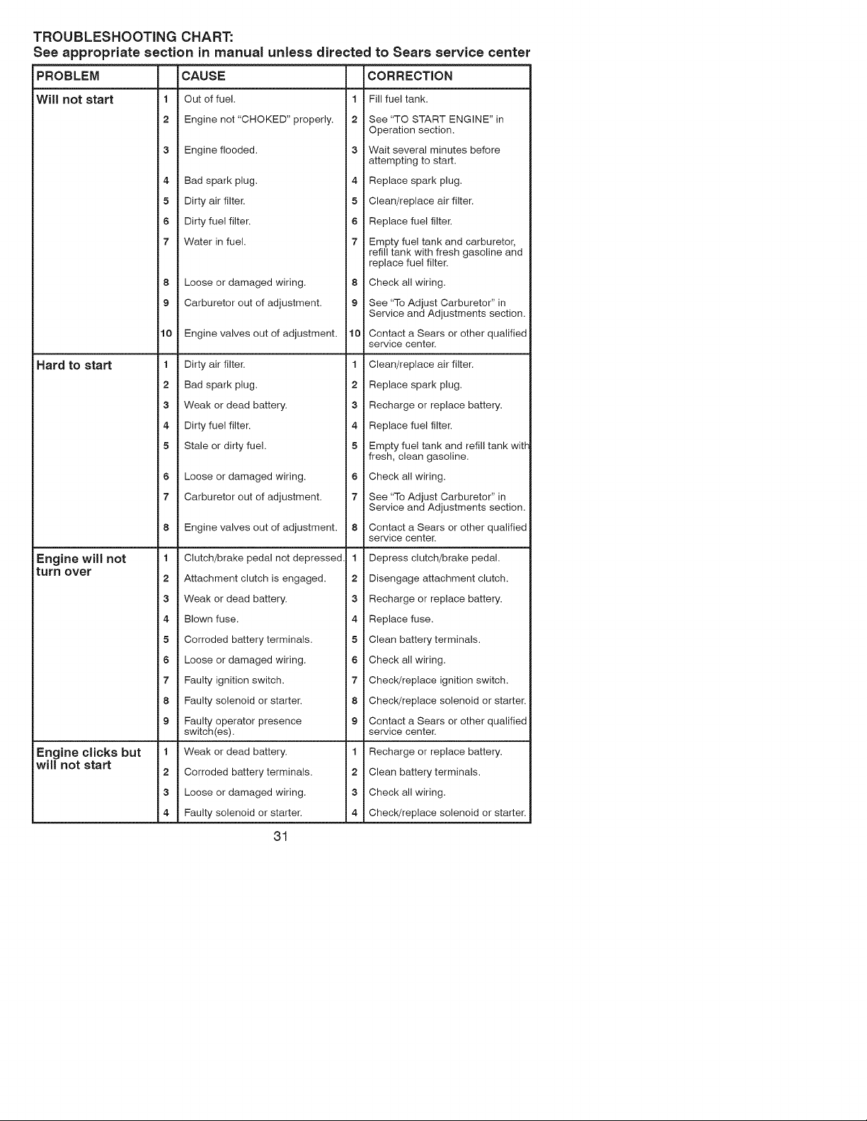
TROUBLESHOOTING CHART:
See appropriate section in manual unless directed to Sears service center
PROBLEM
Will not start
Hard to start
Engine will not
turn over
CAUSE
1 Out of fuel.
2 Engine not "CHOKED" properly.
3 Engine flooded.
Engine clicks but
will not start
4 Bad spark plug.
5 Dirty air filter.
6 Dirty fuel filter.
7 Water in fuel.
8 Loose or damaged wiring.
9 Carburetor out of adjustment.
10 Engine valves out of adjustment.
1 Dirty air filter.
2 Bad spark plug.
3 Weak or dead battery.
4 Dirty fuel filter.
5 Stale or dirty fuel.
6 Loose or damaged wiring.
7 Carburetor out of adjustment.
8 Engine valves out of adjustment.
1 Clutch/brake pedal not depressed
2 Attachment clutch is engaged.
3 Weak or dead battery.
4 Blown fuse.
5 Corroded battery terminals.
6 Loose or damaged wiring.
7 Faulty ignition switch.
8 Faulty solenoid or starter.
9 Faulty operator presence
switch(es).
1 Weak or dead battery.
2 Corroded battery terminals.
3 Loose or damaged wiring.
4 Faulty solenoid or starter.
31
CORRECTION
1 Fill fueltank.
2 See "TO START ENGINE" in
Operation section.
3 Wait several minutes before
attempting to start.
4 Replace spark plug.
5 Clean/replace air filter.
6 Replace fuel filter.
7 Empty fuel tank and carburetor,
refill tank with fresh gasoline and
replace fuel filter.
8 Check all wiring.
9 See "To Adjust Carburetor" in
Service and Adjustments section.
10 Contact a Sears or other qualified
service center
1 Clean/replace air filter.
2 Replace spark plug.
3 Recharge or replace battery.
4 Replace fuel filter.
5 Empty fuel tank and refill tank wig-
fresh, clean gasoline.
6 Check all wiring.
7 See "To Adjust Carburetor" in
Service and Adjustments section.
8 Contact a Sears or other qualified
service center
1 Depress clutch/brake pedal.
2 Disengage attachment clutch.
3 Recharge or replace battery.
4 Replace fuse.
5 Clean battery terminals.
6 Check all wiring.
7 Check/replace ignition switch.
8 Check/replace solenoid or starter.
9 Contact a Sears or other qualified
service center
1 Recharge or replace battery.
2 Clean battery terminals.
3 Check all wiring.
4 Check/replace solenoid or starter.
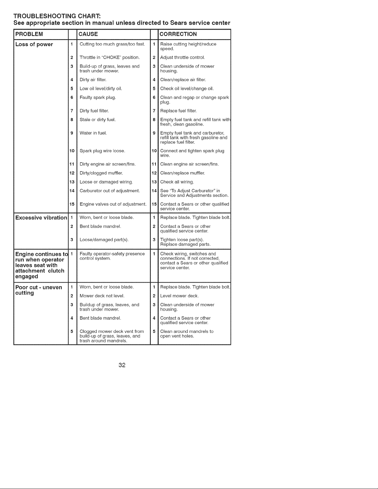
TROUBLESHOOTING CHART:
See appropriate section in manual unless directed to Sears service center
PROBLEM CAUSE
Loss of power 1 Cutting too much grass/too fast. 1
2 Throttle in "CHOKE" position. 2
3 Build-up of grass, leaves and 3
trash under mower.
4 Dirty air filter. 4
5 Low oil level/dirty oil. 5
6 Faulty spark plug. 6
7 Dirty fuel filter.
8 Stale or dirty fuel.
9 Water in fuel.
7
8
10 Spark plug wire loose. 10
11 Dirty engine air screen/fins. 11
12 Dirty/clogged muffler. 12
13 Loose or damaged wiring. 13
14 Carburetor out of adjustment. 14
15 Engine valves out of adjustment. 15
Excessive vibration 1
2
Engine continues to 1
run when operator
leaves seat with
attachment clutch
engaged
Worn, bent or loose blade. 1
Bent blade mandrel. 2
3 Loose/damaged part(s). 3
Faulty operator-safety presence
control system.
Worn, bent or loose blade. 1
Mower deck not level. 2
Buildup of grass, leaves, and 3
trash under mower.
Bent blade mandrel. 4
Clogged mower deck vent from
build-up of grass, leaves, and
trash around mandrels.
CORRECTION
Poor cut - uneven 1
cutting 2
Raise cutting height/reduce
speed.
Adjust throttle control.
Clean underside of mower
housing.
Clean/replace air filter.
Check oil level/change oil.
Clean and regap or change spark
plug.
Replace fuel filter.
Empty fuel tank and refill tank with
fresh, clean gasoline.
Empty fuel tank and carburetor,
refill tank with fresh gasoline and
replace fuel filter.
Connect and tighten spark plug
wire.
Clean engine air screen/fins.
Clean/replace muffler.
Check all wiring.
See "To Adjust Carburetor" in
Service and Adjustments section.
Contact a Sears or other qualified
service center.
Replace blade. Tighten blade bolt.
Contact a Sears or other
qualified service center.
Tighten loose part(s).
Replace damaged parts.
Check wiring, switches and
connections. If not corrected,
contact a Sears or other qualified
service center.
Replace blade. Tighten blade bolt.
Level mower deck.
Clean underside of mower
housing.
Contact a Sears or other
qualified service center.
Clean around mandrels to
open vent holes.
32
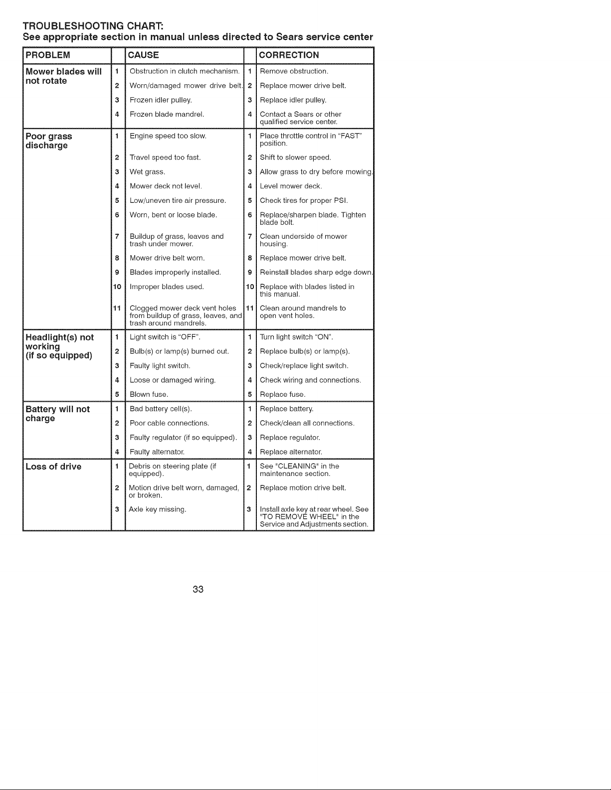
TROUBLESHOOTING CHART:
See appropriate section in manual unless directed to Sears service center
PROBLEM
Mower blades will
not rotate
Poor grass
discharge
Headlight(s) not
working
(if so equipped)
Battery will not
charge
Loss of drive
CAUSE
1 Obstruction in clutch mechanism.
2 Worn/damaged mower drive belt
3 Frozen idler pulley.
4 Frozen blade mandrel.
1 Engine speed too slow.
2 Travel speed too fast.
3 Wet grass.
4 Mower deck not level.
5 Low/uneven tire air pressure.
6 Worn, bent or loose blade.
7 Buildup of grass, leaves and
trash under mower.
8 Mower drive belt worn.
9 Blades improperly installed.
10 Improper blades used.
11 Clogged mower deck vent holes
from buildup of grass, leaves, and
trash around mandrels.
1 Light switch is "OFF".
2 Bulb(s) or lamp(s) burned out.
3 Faulty light switch.
4 Loose or damaged wiring.
5 Blown fuse.
1 Bad battery cell(s).
2 Poor cable connections.
3 Faulty regulator (if so equipped).
4 Faulty alternator.
1 Debris on steering plate (if
equipped).
2 Motion drive belt worn, damaged,
or broken.
3 Axle key missing.
CORRECTION
1 Remove obstruction.
2 Replace mower drive belt.
3 Replace idler pulley.
4 Contact a Sears or other
qualified service center.
1 Place throttle control in "FAST"
position.
2 Shift to slower speed.
3 Allow grass to dry before mowing
4 Level mower deck.
5 Check tires for proper PSI.
6 Replace/sharpen blade. Tighten
blade bolt.
7 Clean underside of mower
housing.
8 Replace mower drive belt.
9 Reinstall blades sharp edge down
10 Replace with blades listed in
this manual.
11 Clean around mandrels to
open vent holes.
1 Turn light switch "ON".
2 Replace bulb(s) or lamp(s).
3 Check/replace light switch.
4 Check wiring and connections.
5 Replace fuse.
1 Replace battery.
2 Check/clean all connections.
3 Replace regulator.
4 Replace alternator.
1 See "CLEANING" in the
maintenance section.
2 Replace motion drive belt.
3 Install axle key at rear wheel. See
"TO REMOVE WHEEL" in the
Service and Adjustments section.
33

TROUBLESHOOTING CHART:
See appropriate section in manual unless directed to Sears service center
PROBLEM CAUSE CORRECTION
Engine "backfires" 1 Engine throttle control not set 1 Move throttlecontrol between
when turning between half and full speed (fast) half and full speed (fast) position
engine "OFF" position before stopping engine, before stopping engine.
Engine dies when 1 Reverse operation system (ROS) 1 Turn ignition key to ROS "ON"
tractor is shifted is not "ON" while mower or other position. See Operation section.
into reverse attachment is engaged.
NEED HORE HELP?
YouqI find tee answer and store on max'tagemyl_omeocom - for free!
o Find this and a[[ your other product manuals online.
o Get answers from our team of home experts.
o Get a personalized maintenance p[an for your home.
o Find information and too[s to he[p with home projects.
bzeaght to you by Seals
34
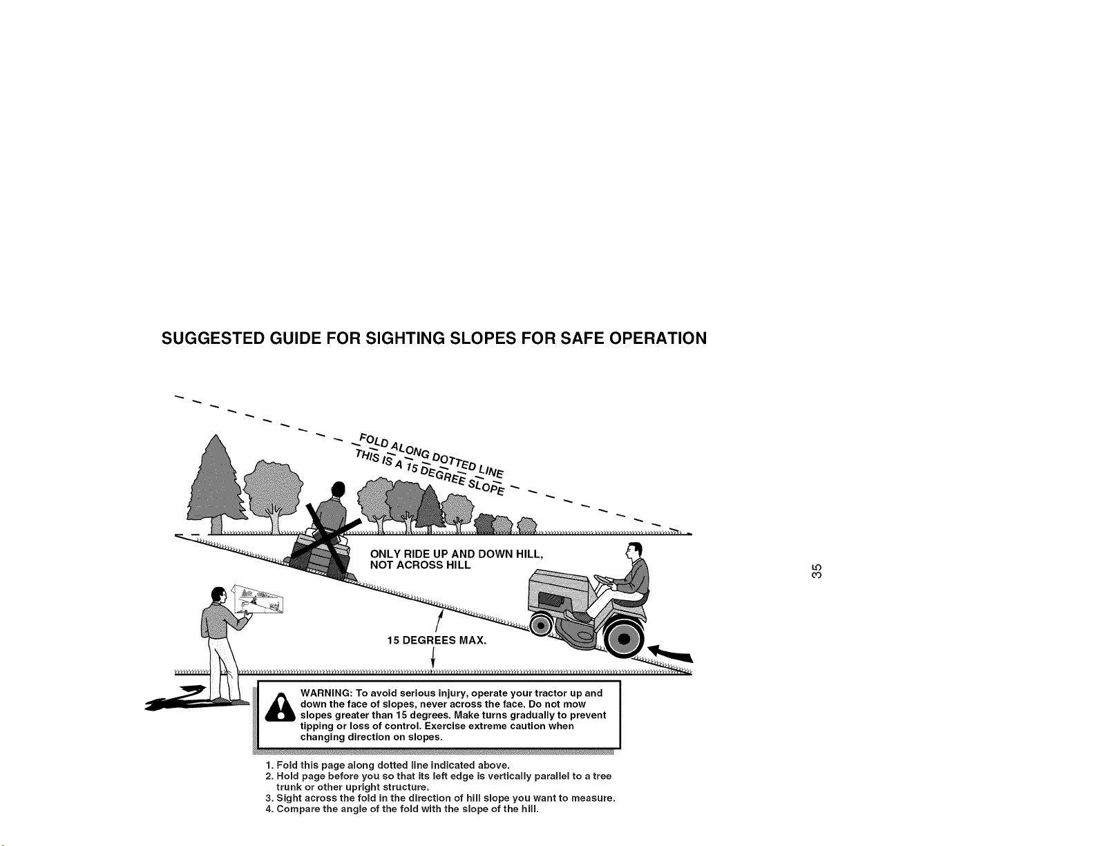
SUGGESTED GUIDE FOR SIGHTING SLOPES FOR SAFE OPERATION
WARNING: To avoid serious injury, operate your tractor up and
down the face of slopes, never across the face. Do not mow
slopes greater than 15 degrees. Make turns gradually to prevent
tipping or loss of control. Exercise extreme caution when
changing direction on slopes.
1. Fold this page along dotted line indicated above.
2. Hold page before you so that its left edge is vertically parallel to a tree
trunk or other upright structure.
3. Sight across the fold in the direction of hill slope you want to measure.
4. Compare the angle of the fold with the slope of the hill.
L_3
o3
Garantia .......................................................... 36 Programa de Mantenimiento .......................... 54
Reglas de Seguridad ...................................... 37 Servicio y Ajustes ........................................... 59
Especificaciones del Producto ........................ 40 Almacenamiento ............................................. 64
Montaje/Pre Operaci6n ................................... 41 Identificaci6n de Problemas ........................... 65
Operaci6n ....................................................... 47 Servicio Sears .............................. Contraporada
Mantenimiento ................................................ 54
Garantia para equipos tractores Craftsman
GARANTiA COMPLETA DE CRAFTSMAN
POR DOS AI_JOS desde la fecha de compra, todas las partes no sustituibles de este equipo tractor estan
garantizadas contra cualquier defecto de material o mano de obra. Una parte no sustituible defectuosa
recibira reparaci6n o reemplazo gratuito en casa si la reparaci6n es imposible.
POR CINCO AIklOS desde la fecha de compra, el bastidor y el eje delantero de este equipo tractor estan
garantizados contra cualquier defecto de material o mano de obra. Un bastidor o eje delantero defectuoso
recibira reparaci6n o reemplazo gratuito en casa si la reparaci6n es imposible.
DURANTE 90 DiAS desde la fecha de compra, la bateria (una parte sustituible) de este equipo tractor
esta_ garantizada contra cualquier defecto de material o mano de obra (nuestra prueba comprueba que no
contendra carga). Una bateria defectuosa recibir_, un reemplazo gratuito en casa.
GARANTiA LIMITADA DE POR VIDA ADICIONAL en el EJE DELANTERO DE HIERRO COLADO (8i
esta provisto)
DURANTE EL TIEMPO EN QUE SE USE por el propietario original despues del quinto afio a partir de la
fecha de compra, el eje delantero de hierro colado (si estb_ provisto) de este equipo tractos estb_ garantizado
contra cualquier defecto de material o mano de obra. Con el comprobante de compra, un eje delantero de
hierro colado recibir_, un reemplazo gratuito en casa.
SERVIClO DE GARANTiA
Para conocer los detalles de la cobertura de garantia para obtener una reparaci6n o reemplazo gratuito,
Ilame al 1-800-659-5917 6 visite el sitio web: www. craftsman.com
En todos los casos anteriores, si el reemplazo es imposible, el equipo tractor ser_. sustituido sin cargo con
el mismo modelo o uno equivalente.
Toda la cobertura de garantia anterior serb_ nula si este equipo tractor se utiliza alguna vez para brindar
servicios comerciales o si se alquila a otra persona.
Esta garantia cubre 0 NICAM ENTE defectos de material y mano de obra. La cobertura de garantia NO incluye:
• Partes sustituibles (excepto la bateria) que se puedan desgastar por el uso normal dentro del periodo de
garantia incluso, pero sin limitarse a, cuchillas, bujias, filtros de aire, correas y filtros de aceite.
• Servicios de mantenimiento estandar, cambios de aceite o afinaciones.
• Reemplazo o reparaci6n de neum_.ticos por pinchazos causados por objetos externos como clavos,
espinas, tocones o vidrios.
• Reemplazo o reparaci6n de neumaticos o ruedas por desgaste normal, accidentes o por operaci6n o
mantenimiento incorrectos.
• Reparaciones necesarias por abuso del operador incluso, pero sin limitarse a, dafios causados por
remolcar objetos que superen la capacidad del equipo tractor, chocar contra objetos que doblen el
bastidor, el ensamble del eje o el cigOe_al o sobrepasar la velocidad del motor.
• Reparaciones necesarias por negligencia del operador, incluso (pero sin limitarse a ello) da[_os electricos
y mecanicos causados por el almacenamiento incorrecto, por no usar el grado y la cantidad correctos de
aceite de motor, por no mantener del muelle libre de residuos inflamables o por no mantener el equipo
tractor de acuerdo con las instrucciones que contiene el manual del operador.
• Limpieza o reparaciones del motor (sistema de combustible) cuando se determina que se us6
combustible contaminado y oxidado (sarro). En general, el combustible debe usarse dentro de los 30
dias posteriores a su compra.
• Deterioro y desgaste normal de los acabados exteriores o sustituci6n de r6tulos de productos.
Esta garantia le otorga derechos legales especificos, y usted tambi&n puede tener otros derechos que
varian de un estado a otro.
Sears Brands Management Corporation, Hoffman Estates, IL 60179
36
_PELIGRO: Esta Maquina cortadora es capaz de amputar las manosy los pies y de lanzar
objetos, si no se observan las instrucciones de seguridad siguientes se pueden producir
lesiones graves o la muerte.
_ADVERTENCIA: Siempre desconecte el alam-
bre de la bujia y p6ngalo donde no pueda entrar
en contacto con la bujia, para evitar el arranque
por acciciente, durante la preparaci6n, el trans-
porte, el ajuste o cuando se hacen reparaciones.
_DVERTENOIA: No avance cuesta abajo a pu n-
to muerto ya que podria perder elcontrol del tractor.
_bADVERTENCiA: Remolque solamente los
accesorios recomendados y conformes alas
caracteristicas indicadas por el fabricante de su
tractor. Tenga cuidacio y prudencia al utilizar el
tractor. Cuando se encuentre en un declive, oper
utilizando exclusivamente la velocidad m&s baja.
En caso de un declive una carga excesiva po-
dria resultar peligrosa. Los neum&ticos pueden
perder la tracci6n con el suelo y hacerle perder
el control de su tractor.
_ADVERTENCIA: El tubo de escape del motor,
algunos de sus constituyentes y algunos com-
)onentes del vehiculo contienen o desprenden
productos quimicos conocidos en el Estado de
California como causa de c&ncer y defectos al
nacimiento u otros daSos reproductivos.
_.DVERTENCIA: Los bornes, terminales y ac-
cesorios relativos de la bateria contienen plomo
o compuestos de plomo, productos quimicos
conocidos en el Estado de California como causa
de c&ncer y defectos al nacimiento u otros daSos
reproductivos. Lavar las manos despues de
manipularlos.
FUNCIONAMIENTO GENERAL
Leer, entender y seguir todas las instrucciones
sobre la m&quina y en el manual antes de
empezar.
No poner las manos o los pies cerca de partes
giratorias o debajo de la m&quina, mantener
siempre limpia la abertura de descarga.
Permitir el funcionamiento de la m&quina s61o
a adultos que tengan familiaridad con las
instrucciones.
Limpiar el &rea de objetos como piedras,
juguetes, cables, etc. que pueden ser recogi-
dos y disparados con las cuchillas.
Asegurarse de que el &rea este libre de otras
personas antes de ponerla en marcha. Parar
la m_.quina si alguien entra en el &tea.
Nunca Ilevar pasajeros.
No cortar marcha atr&s al no ser absolu-
tamente necesario. Mirar siempre abajo y
delante mientras se procede atr&s.
Nunca dirigir el material descargado hacia na-
die. Evitar descargar material contra paredes
u obstrucciones. El material podria rebotar
hacia el operador. Parar las cuchillas cuando
se pasan superficies de grava.
37
• No maneje la m&quina si no tiene la trampa
para cesped completa, la canaleta de descarga
u otros dispositivos de seguridad en su lugar
y en funcionamiento.
• Ralentizar antes de girar.
• Nunca dejar una m&quina encendida sin vigi-
lancia. Apagar siempre las cuchillas, poner el
freno de estacionamiento, parar el motor, y
quitar las Ilaves antes de bajar.
• Desenganche las hojas cuando no este cortan-
do cesped. Apague el motor y espere hasta que
todas las partes se detengan por completo an-
tes de limpiar la m&quina, retirar la trampa para
cesped o destapar la canaleta de descarga.
Hacer funcionar la m&quina s61o con la luz del
dia o luz artificial buena.
No hacer funcionar la m&quina estando bajo
los efectos de alcohol o droga.
Porter atenci6n al tr&fico cuando se opera
cerca de calles o se cruzan.
Porter la m&xima atenci6n al cargar o descar-
gar la m&quina en una caravana o cami6n.
Llevar siempre gafas de protecci6n cuando se
hace funcionar la m&quina.
Los datos indican que los operadores a partir
de los 60 aSos est&n afectados por un gran
porcentaje de heridas relativas a la conducci6n
del cortacesped. Estos operadores tendrian
que evaluar su habilidad de hacer funcionar
el cortacesped de modo Io bastante seguro
para proteger a si mismos y a otras personas
de heridas graves.
• Seguir las recomendaciones del fabricante
para los pesos y contrapesos de las ruedas.
• Mantener la m&quina libre de hierba, hojas u
otros escombros que pueden tocar el tubo de
escape/partes del motor calientes y quemarse.
No permitir que el puente del cortacesped
cargue hojas u otros residuos que pueden
causar acumulaciones. Limpiar toda salpica-
dura de aceite o carburante antes de hacer
operaciones sobre la m&quina o guardarla.
Dejarla enfriar antes de guardarla.
II. FUNCIONAMIENTO EN PENDIENTES
Las pendientes son el mayor factor de accidentes
relativos a la perdida de control y vuelco, que
pueden causar severas heridas o muerte. El fun-
cionamiento en pendientes requiere una atenci6n
extra. Si no es posible hacer marcha atr&s en una
pendiente o site sientes incomodo, no la cortes.
• Cortar hacia arriba y abajo de una pendiente,
no de modo horizontal.
• Poner atenciones a los hoyos, las raices, los
bultos, las piedras u otros objetos escondidos.
El terreno irregular puede volcar la m&quina.
La hierba alta puede esconder obst&culos.
• Escogerunavelocidaddemarchabajade
modoquenoseanecesariopararseocambiar
estando en una pendiente.
• No cortar la hierba mojada. Las ruedas pueden
perder tracci6n.
Poner siempre una marcha cuando se est&
en pendientes. No poner en punto muerto e ir
cuesta abajo.
• Evitar arrancar, pararse o girar en una pendien-
te. Si las ruedas pierden tracci6n, desconectar
las cuchillas y proceder despacio cuesta abajo
en la pendiente.
• Mantener todo los movimientos en las pen-
dientes lentos y gradual. No hacer cambios
repentinos de velocidad o direcci6n, ya que
pueden causar el escape de la m&quina.
•Poner la m&xima atenci6n cuando la m&quina
funciona con captadores de hierba u otros
dispositivos enganchados; pueden afectar la
estabilidad de la m&quina. No usar en pendi-
entes empinados.
• No intentar estabilizar la m&quina poniendo el
pie en el terreno.
• No cortar cerca de bajadas, cunetas y orillas.
Las m&quina puede volcarse improvisamente
si una rueda est& en el borde o se hunde.
Ill, NINOS
_,ADVER'['ENCIA: LOS NINOS PUEDEN
SUFRIR DANOS CON EL USO DE ESTE EQUI-
PO. La Academia Estadounidense de Pediatria
(American Academy of Pediatrics) recomienda
que s61o se permita a niSos con una edad mini-
ma de 12 aSos manejar m&quinas cortacesped
manuales, y al menos de 16 a_os para manejar
tractores cortacesped.
Si el operador no pone atenci6n a la presencia
de los niSos pueden ocurrir accidentes tr&gicos.
Los niSos a menudo est&n atraidos por la m&qui-
nay las actividad de cortar. No dar por hecho
de que los niSos se queden adonde estaban la
Qltima vez que los vistes.
• Mantener los niSos fuera del &rea de corte y
vigilados por un adulto responsable que no sea
el operador.
• Estar alerta y apagar la m&quina si un ni_os
entra en el &rea.
• Antes y durante la marcha atr&s, mirar adelante
y abajo para ver si hay niSos pequeSos.
• Nunca Ilevar niSos, incluso si hay las cuchillas
apagadas. Podrian caer y herirse seriamente
o interferir con el funcionamiento seguro de la
m&quina, los niSos que se han Ilevado prec-
edentemente pueden aparecer de pronto en el
&rea de corte por otro paseo y ser atropellados
o tumbados por la m&quina.
• Nunca dejar que los niSos manipulen la m&-
quina.
• Tener el m&ximo cuidado cuando se acerca
a cantos ciegos, arbustos, &rboles u otros
objetos que pueden impedir la vista de niSos.
iV, REMOLQUE
• Remolcar s61o con una m&quina que tenga un
gancho diseSado para remolcar. Enganchar el
equipo o remolcar s61o en el punto dispuesto
al efecto.
• Seguir las recomendaciones del productor con
respecto a los limites del equipo por remolcar
y el remolque en pendientes.
• Nunca permitir que niSos u otras personas
esten dentro del equipo por remolcar.
• En pendientes, el peso del equipo remolcado
puede causar la p@dida de tracci6n y la p@-
dida de control.
• Viajar despacio y dejar m&s distancia para
frenar.
V. SERViCIO
MANIPULACI6N SEGURA DE LA GASOLINA
Para evitar heridas personales o da_os alas
cosas, poner el m&ximo cuidado a la hora de
manipular la gasolina. La gasolina es extrema-
mente inflamable y los vapores son explosivos.
• Apagar todos los cigarrillos, cigarros, pipas y
otras fuentes de ignici6n.
• Usar s61o contenedores para gasolina aproba-
dos.
• Nunca quitar el tap6n de la gasolina o aSadir
carburante con el motor en marcha, dejar
enfriar el motor antes del abastecimiento de
la gasolina.
• Nunca abastecer la maquina al interior de un
local.
• Nunca guardar la maquina o el contenedor
del carburante donde haya una llama abierta,
chispas o una luz piloto como un calentador
de agua u otros dispositivos.
• Nunca Ilenar los contenedores al interior de
un vehiculo o en una caravana o cami6n
recubiertos con un forro de plastico. Colocar
siempre los contenedores en el terreno lejos
del vehiculo cuando se esta Ilenando.
• Quitar el equipo de gas del cami6n o caravana
y abastecerlo en el terreno. Si no es posible,
abastecer dicho equipo con un contenedor por-
tatil, mas bien que de un surtidor de gasolina.
• Mantener la boquilla a contacto del borde
del dep6sito de carburante o la abertura del
contenedor durante toda la operaci6n de
abastecimiento. No utilizar un dispositivo con
boquilla cerrada-abierta.
• Si se vierte carburante sobre la ropa, cambi-
arse la ropa inmediatamente.
• Nunca Ilenar el dep6sito mas de Io debido.
Volver a colocar el tap6n del gas y cerrar de
modo firme.
38
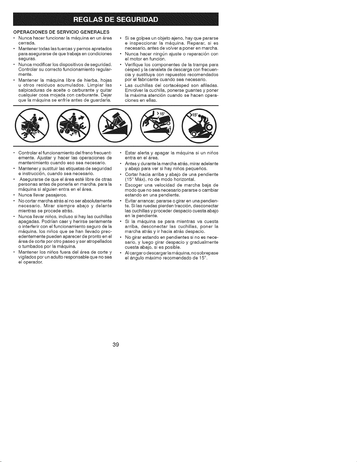
OPERACIONES DE SERVICIO GENERALES
• Nunca hacer funcionar la m&quina en un &rea
cerrada.
• Mantenertodas lastuercas y pemos apretados
para asegurarse de que trabaja en condiciones
seguras.
• Nunca modificar los dispositivos de seguridad.
Controlar su correcto funcionamiento regular-
mente.
• Mantener la m&quina libre de hierba, hojas
u otros residuos acumulados. Limpiar las
salpicaduras de aceite o carburante y quitar
cualquier cosa mojada con carburante. Dejar
que la m&quina se enfrJe antes de guardarla.
• Si se golpea un objeto ajeno, hay que pararse
e inspeccionar la ma.quina. Reparar, si es
necesario, antes de volver a poner en marcha.
• Nunca hacer ningt_n ajuste o reparaci6n con
el motor en funci6n.
• Verifique los componentes de la trampa para
cesped y la canaleta de descarga con frecuen-
ciay sustituya con repuestos recomendados
por el fabricante cuando sea necesario.
• Las cuchillas del cortacesped son afiladas.
Envolver la cuchilla, ponerse guantes y poner
la ma.xima atenci6n cuando se hacen opera-
ciones en elias.
Controlar el funcionamiento del freno frecuent-
emente. Ajustar y hacer las operaciones de
mantenimiento cuando eso sea necesario.
Mantener y sustituir las etiquetas de seguridad
e instrucci6n, cuando sea necesario.
Asegurarse de que el &rea este libre de otras
personas antes de ponerla en marcha, para la
m&quina si alguien entra en el &tea.
Nunca Ilevar pasajeros.
No cortar marcha atr&s al no ser absolutamente
necesario. Mirar siempre abajo y delante
mientras se procede atr&s.
Nunca Ilevar niSos, incluso si hay las cuchillas
apagadas. Podrian caer y herirse seriamente
o interferir con el funcionamiento seguro de la
m&quina, los niSos que se han Ilevado prec-
edentemente pueden aparecer de pronto en el
&rea de corte por otro paseo y ser atropellados
o tumbados por la m&quina.
Mantener los niSos fuera del &rea de corte y
vigilados por un adulto responsable que no sea
el operador.
• Estar alerta y apagar la m&quina si un niSos
entra en el &rea.
• Antes y durante la marcha atr&s, mirar adelante
y abajo para ver si hay niSos pequeSos.
• Cortar hacia arriba y abajo de una pendiente
(15 ° M&x), no de modo horizontal.
• Escoger una velocidad de marcha baja de
modo que no sea necesario pararse o cambiar
estando en una pendiente.
• Evitar arrancar, pararse o girar en una pendien-
te. Si las ruedas pierden tracci6n, desconectar
las cuchillas y proceder despacio cuesta abajo
en la pendiente.
• Si la m&quina se para mientras va cuesta
arriba, desconectar las cuchillas, poner la
marcha atr&s y ir hacia atr&s despacio.
• No girar estando en pendientes si no es nece-
sario, y luego girar despacio y gradualmente
cuesta abajo, si es posible.
• AI cargar o descargar la m&quina, no sobrepase
el &ngulo m&ximo recomendado de 15°.
39
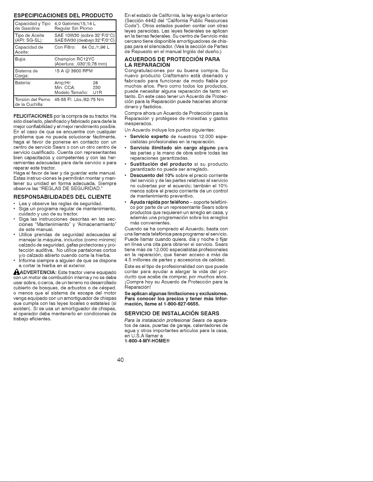
ESPECIFICACIONES DEL PRODUCTO
Capacidad y Tipo 4,0 Galones/15,14 L
de Gasolina: Regular Sin Plomo
Tipo de Aceite SAE 10W30 (sobre 32°F/0°C)
(API: SG-SL): SAE 5W30 (deabajo 32°F/0°C)
Capacidad de Con Filtro: 64 Oz./1,96 L
Aceite:
Bujia Champion RC12YC
(Abertura: .030"/0,76 mm)
Sistema de 15 A @ 3600 RPM
Carga:
Bateria: Amp/Hr: 28
Min. CCA: 230
Modelo Tama_o: U1R
Torsi6n del Perno 45-55 Ft. Lbs./62-75 Nm
de la Cuchilla:
FEUCITACIONES por la compra de su tractor. Ha
sido diseSado, planificado y fabricado para darle la
mejor confiabilidad y el mejor rendimiento posible.
En el caso de que se encuentre con cualquier
problema que no pueda solucionar f&cilmente,
haga el favor de ponerse en contacto con un
centro de servicio Sears o con un otro centro de
servicio cualificado. Cuenta con representantes
bien capacitados y competentes y con las her-
ramientas adecuadas para darle servicio o para
reparar este tractor.
Haga el favor de leer y de guardar este manual.
Estas instruc-ciones le permitir&n montar y man-
tener su unidad en forma adecuada. Siempre
observe las "REGLAS DE 8EGURIDAD."
RESPONSABILIDADES DEL CMENTE
• Lea y observe las reglas de seguridad.
• Siga un programa regular de mantenimiento,
cuidado y uso de su tractor.
• Siga las instrucciones descritas en las sec-
clones "Mantenimiento" y 'Almacenamiento"
de este manual.
• Utilice prendas de seguridad adecuadas al
manejar la m&quina, incluidos (como minimo)
calzado de seguridad, gafas protectoras y pro-
tecci6n auditiva. No utilice pantalones cortos
y/o calzado abierto cuando corte la hierba.
• Informe siempre a alguien de que se dispone
a cortar la hierba en el exterior.
_DVERTENCIA: Este tractor viene equipado
con un motor de combusti6n interna y no se debe
usar sobre, o cerca, de un terreno no desarrollado
cubierto de bosques, de arbustos o de cesped,
o menos que el sistema de escape del motor
venga equipado con un amortiguador de chispas
que cumpla con las leyes locales o estatales (si
existen). Si se usa un amortiguador de chispas,
el operador debe mantenerlo en condiciones de
trabajo eficientes.
En el estado de California, la Icy exige Io anterior
(Secci6n 4442 del "California Public Resources
Code"). Otros estados pueden contar con otras
leyes parecidas. Las leyes federales se aplican
en la tierras federales. Su centro de Servicio m&s
cercano tiene disponible amortiguadores de chis-
pas para el silenciador. (Vea la secci6n de Partes
de Repuesto en el manual Ingles del dueSo.)
ACUERDOS DE PROTECCION PARA
LA REPARACION
Congratulaciones por su buena compra. Su
nuevo producto Craftsman,; est& diseSado y
fabricado para funcionar de modo fiable por
muchos aSos. Pero como todos los productos,
puede necesitar alguna reparaci6n de tanto en
tanto. En este caso tener un Acuerdo de Protec-
ci6n para la Reparaci6n puede hacerles ahorrar
dinero y fastidios.
Compre ahora un Acuerdo de Protecci6n para la
Reparaci6n y protegese de molestias y gastos
inesperados.
Un Acuerdo incluye los puntos siguientes:
• Servicio experto de nuestros 12.000 espe-
cialistas profesionales en la reparaci6n.
• Servicio ilimitado sin cargo alguno para
las partes y la mano de obra sobre todas las
reparaciones garantizadas.
• Sustitucion del producto si su producto
garantizado no puede ser arreglado.
• Descuento del 10% sobre el precio corriente
del servicio y de las partes relativas al servicio
no cubiertas por el acuerdo; tambien el I0%
menos sobre el precio corriente de un control
de mantenimiento preventivo.
• Ayuda rapida pot telefono- soporte telef6ni-
co por parte de un representante Sears sobre
productos que requieren un arreglo en casa, y
adema.s una programaci6n sobre los arreglos
mas convenientes.
Cuando se ha comprado el Acuerdo, basta con
una Ilamada telef6nica para programar el servicio.
Puede Ilamar cuando quiera, dia y noche o fijar
en linea una cita para obtener el servicio. Sears
tiene mas de 12.000 especialistas profesionales
en la reparaci6n, que tienen acceso a mas de
4.5 millones de partes y accesorios de calidad.
Este es el tipo de profesionalidad con que puede
contar para ayudar a alargar la vida del pro-
ducto que acaba de comprar, por muchos aSos.
iCompre hoy su Acuerdo de Protecci6n para la
Reparaci6n!
Se aplican algunas limitaciones y exclusiones.
Para conocer Ice precios y tenet mas Infor-
maci6n, llame al 1-800-827-6655.
SERVICIO DE INSTALACION SEARS
Para la instalaci6n profesional Sears de apara-
tos de casa, puertas de garaje, calentadores de
agua y otros importantes articulos para la casa,
en U.S.A Ilamar a
1-800-4-MY-HOME®
40
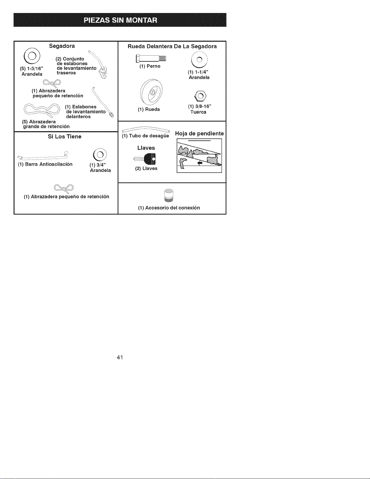
Segadora
(2) Conjunto
de eslabones \\
de levantamiento _
(5) 1=3/16" trasetos _
Arandela _
(1) Abtazadera
peque_o de retenci6n
(5) Abrazadera
grande de retenci6n
Si Los Tiene
(1) Barra Antioscilaci6n
©
(1)3/4"
Arandela
(1) Abrazadeta peque_o de retenci6n
Rueda Delantera De La Segadora
(1) Perno
(i) i-i/4"
Arandela
(1) Rueda
©
(I) 3/8=I 6"
Tuerca
(1) Tubo de desagQe
Llaves
(2) Llaves
Hoja de pendiente
(1) Accesorio del cone×i6n
41
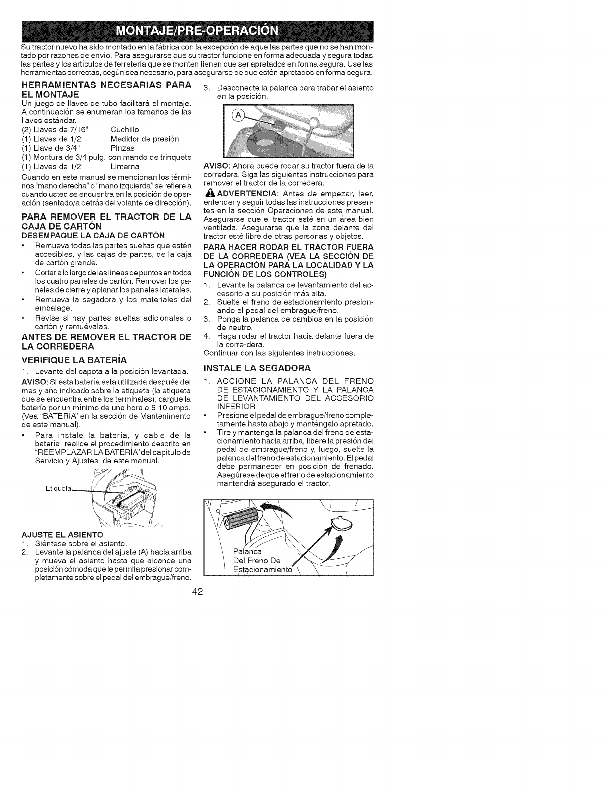
Su tractor nuevo ha sido montado en la f&brica con la excepci6n de aquellas partes que no se han mon-
tado por razones de envJo. Para asegurarse que su tractor funcione en forma adecuada y segura todas
las partes y los artJculos de ferreterJa que se monten tienen que ser apretados en forma segura. Use las
herramientas correctas, segQn sea necesario, para asegurarse de que esten apretados en forma segura.
HERRAMJENTAS NECESARIAS PARA
EL MONTAJE
Un juego de Ilaves de tubo facilitar& el montaje.
A continuaci6n se enumeran los tamaSos de las
Ilaves est&ndar.
(2) Llaves de 7/16" Cuchillo
(1) Llaves de I/2" Medidor de presi6n
(I) Llave de 3/4" Pinzas
(1) Montura de 3/4 pulg. con mando de trinquete
(1) Llaves de 1/2" Linterna
Cuando en este manual se mencionan los t@mi-
nos "mano derecha" o "mano izquierda" se refiere a
cuando usted se encuentra en la posici6n de oper-
aci6n (sentado/a detr&s del volante de direcci6n).
PARA REMOVER EL TRACTOR DE LA
CAJA DE CARTON
DESEMPAQUE LA CAJA DE CART6N
Remueva todas las partes sueltas que esten
accesibles, y las cajas de partes, de la caja
de cart6n grande.
Cortar a Io largo de las IJneasde puntos en todos
los cuatro paneles de cart6n. Remover los pa-
neles de cierre y aplanar los paneles laterales.
Remueva la segadora y los materiales del
embalage.
Revise si hay partes sueltas adicionales o
cart6n y remuevalas.
ANTES DE REMOVER EL TRACTOR DE
LA CORREDERA
VERIFIQUE LA BATERJA
1. Levante del capota a la posici6n levantada.
AVISO: Si esta baterJa esta utilizada despues del
rues y aSo indicado sobre la etiqueta (la etiqueta
que se encuentra entre los terminales), cargue la
bateria por uq mJnimo de una hora a 6-10 amps.
(Vea "BATERI_' en la secci6n de Mantenimento
de este manual).
Para instale la baterJa, y cable de la
baterJa, realice el procedim)ento descrito en
"REEM PLAZAR LA BATERIA_'del capitulo de
Servicio y Ajustes de este manual.
Etiqueta_
AJUSTE EL ASIENTO
1. Sientese sobre el asiento.
2. Levante la palanca del ajuste (A) hacia arriba
y mueva el asiento hasta que alcance una
posici6n c6moda que le permita presionar com-
pletamente sobre el pedal del embrague/freno.
3. Desconecte la palanca para trabar el asiento
en la posici6n.
AVlSO: Ahora puede rodar su tractor fuera de la
corredera. Siga las siguientes instrucciones para
remover el tractor de la corredera.
_,ADVERTENCIA: Antes de empezar, leer,
entender y seguir todas las instrucciones presen-
tes en la secci6n Operaciones de este manual.
Asegurarse que el tractor este en un &rea bien
ventilada. Asegurarse que la zona delante del
tractor este libre de otras personas y objetos.
PARA HACER RODAR EL TRACTOR FUERA
DE LA CORREDERA (VEA LA SECCI6N DE
LA OPERACI6N PARA LA LOCALIDAD Y LA
FUNCI6N DE LOS CONTROLES)
1. Levante la palanca de levantamiento del ac-
cesorio a su posici6n m&s alta.
2. Suelte el freno de estacionamiento presion-
ando el pedal del embrague/freno.
3. Ponga la palanca de cambios en la posici6n
de neutro.
4. Haga rodar el tractor hacia delante fuera de
la corre-dera.
Continuar con las siguientes instrucciones.
JNSTALE LA SEGADORA
1, ACCIONE LA PALANCA DEL FRENO
DE ESTACIONAMIENTO Y LA PALANCA
DE LEVANTAMIENTO DEL ACCESORIO
iNFERIOR
Presione el pedal de embrague/freno comple-
tamente hasta abajo y mantengalo apretado.
Tire y mantenga la palanca del freno de esta-
cionamiento hacia arriba, libere la presi6n del
pedal de embrague/freno y, luego, suelte la
palancadel freno de estacionamiento. Elpedal
debe permanecer en posici6n de frenado.
AsegQrese de que el freno de estacionamiento
mantendr& asegurado el tractor.
42
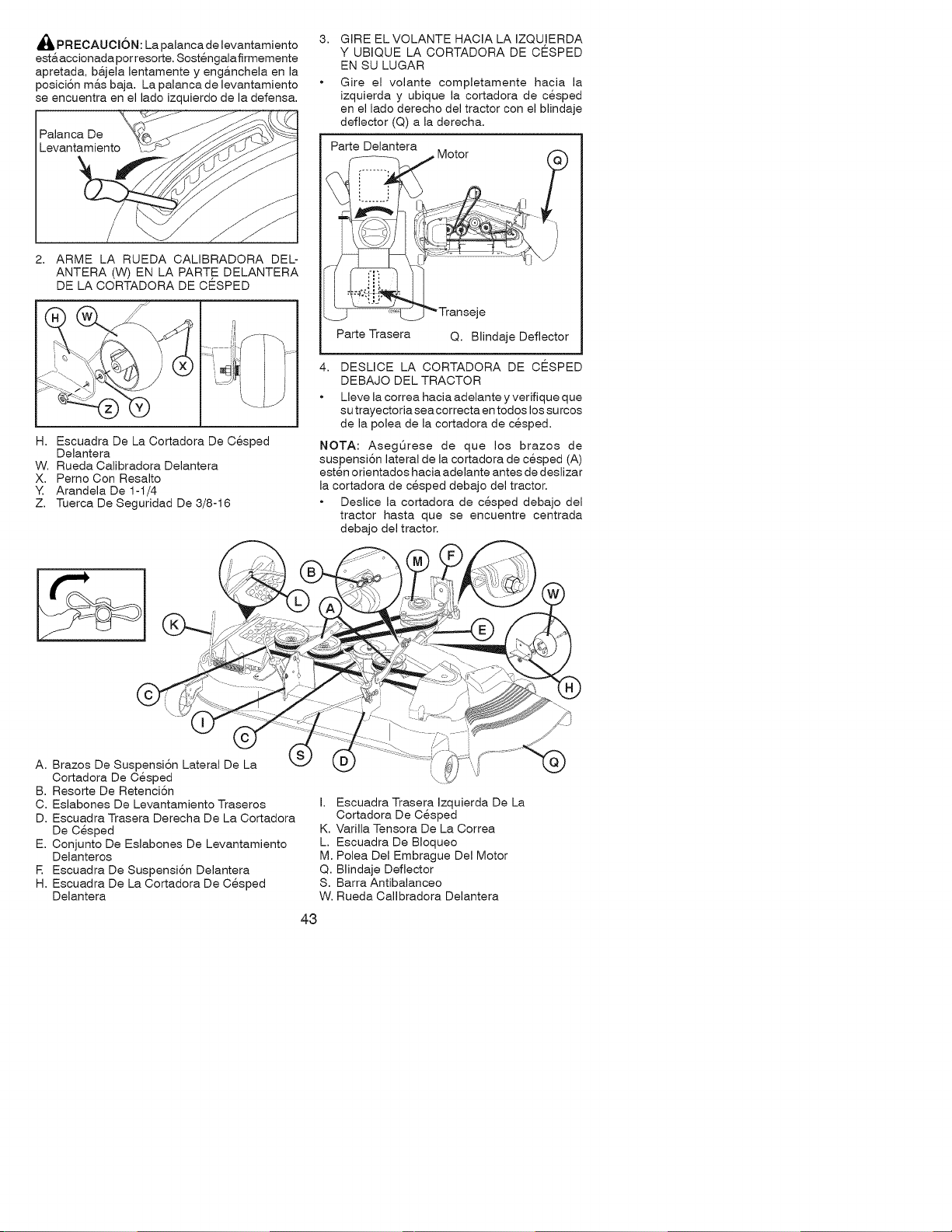
_,PRECAUCI6N: La palanca de levantamiento
est&accionada por resorte. Sostengalafirmemente
apretada, ba.jela lentamente y eng&nchela en la
posici6n m&s baja. La palanca de levantamiento
se encuentra en el lado izquierdo de la defensa.
Palanca De
2. ARME LA RUEDA CALIBRADORA DEL-
ANTERA (W) EN LA PART,E DELANTERA
DE LA CORTADORA DE CESPED
H. Escuadra De La Cortadora De Cesped
Delantera
W. Rueda Calibradora Delantera
X. Pemo Con Resalto
Y. Arandela De 1-1/4
Z. Tuerca De Seguridad De 3/8-16
GIRE EL VOLANTE HACIA LA IZQU!ERDA
Y UBIQUE LA CORTADORA DE CESPED
EN SU LUGAR
Gire el volante completamente hacia la
izquierda y ubique la cortadora de cesped
en el lado derecho del tractor con el blindaje
deflector (Q) a la derecha.
Parte Delantera
or
-- i j_-J
Parte Trasera Q. Blindaje Deflector
DESLICE LA CORTADORA DE CESPED
DEBAJO DEL TRACTOR
Lleve la correa hacia adelante y verifique que
su trayectoria sea correcta en todos los su rcos
de la polea de la cortadora de cesped.
NOTA: AsegQrese de que los brazos de
suspensi6n lateral de la cortadora de cesped (A)
esten orientados hacia adelante antes de deslizar
la cortadora de cesped debajo del tractor.
Deslice la cortadora de cesped debajo del
tractor hasta que se encuentre centrada
debajo del tractor.
A. Brazos De Suspensi6n Lateral De La
Cortadora De Cesped
B. Resorte De Retenci6n
C. Eslabones De Levantamiento Traseros
D. Escuadra Trasera Derecha De La Cortadora
De Cesped
E. Conjunto De Eslabones De Levantamiento
Delanteros
F. Escuadra De Suspensi6n Delantera
H. Escuadra De La Cortadora De Cesped
Delantera
I. Escuadra Trasera Izquierda De La
Cortadora De Cesped
K. Varilla Tensora De La Correa
L. Escuadra De Bloqueo
M. Polea Del Embrague Del Motor
Q. Blindaje Deflector
S. Barra Antibalanceo
W. Rueda Calibradora Delantera
43
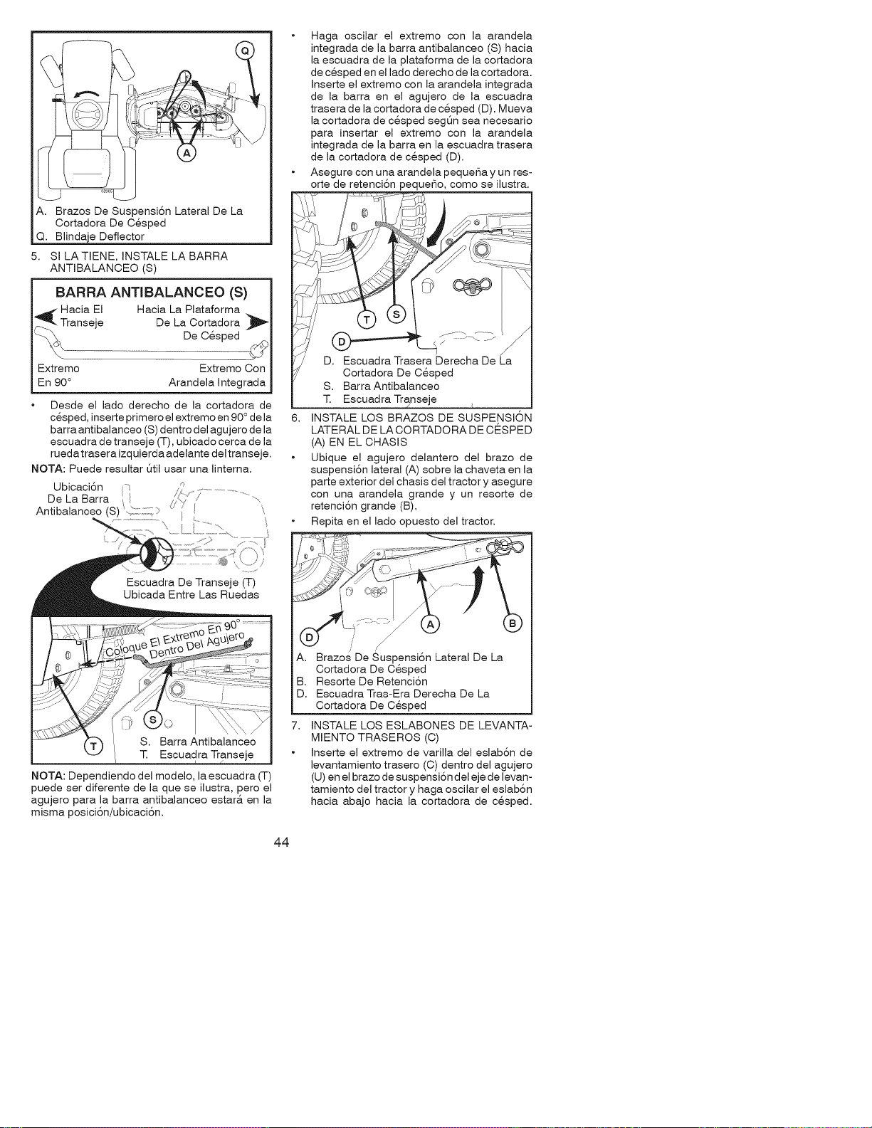
A. Brazos De Suspensi6n Lateral De La
Cortadora De Cesped
Q. Blindaje Deflector
5. Sl LATIENE, INSTALE LA BARRA
ANTIBALANCEO (S)
BARRA ANTIBALANCEO (S)
_ Hacia El Hacia La Plataforma
Transeje De La Cortadora
DeCesped /4_
Extremo Extremo Con
En 90 ° Arandela Integrada
Desde el lado derecho de la cortadora de
cesped, inserte primero el extremo en 90 ° de la
barra antibalanceo (S) dentro del agujero de la
escuadra de transeje (T), ubicado cerca de la
ruedatrasera izquierda adelante del transeje.
NOTA: Puede resultar Qtil usar una linterna.
Escuadra De Transeje (T)
Ubicada Entre Las Ruedas
EscuadraTranse
NOTA: Dependiendo del modelo, la escuadra (T)
puede ser diferente de la que se ilustra, pero el
agujero para la barra antibalanceo estar& en la
misma posici6n/ubicaci6n.
7_
Haga oscilar el extremo con la arandela
integrada de la barra antibalanceo (S) hacia
la escuadra de la plataforma de la cortadora
de cesped en el lado derecho de la cortadora.
Inserte el extremo con la arandela integrada
de la barra en el agujero de la escuadra
trasera de la cortadora de cesped (D). Mueva
la cortadora de cesped segQn sea necesario
para insertar el extremo con la arandela
integrada de la barra en la escuadra trasera
de la cortadora de cesped (D).
Asegure con una arandela peque_a y un res-
orte de retenci6n pequeSo, como se ilustra.
D. Escuadra Trasera Derecha De La
Cortadora De Cesped
S. Barra Antibalanceo
T. Escuadra Transeje
6. INSTALE LOS BRAZOS DE SUSPE,NSION
LATERAL DE LA CORTADORA DE CESPED
(A) EN EL CHASIS
Ubique el agujero delantero del brazo de
suspensi6n lateral (A) sobre la chaveta en la
parte exterior del chasis del tractor y asegure
con una arandela grande y un resorte de
retenci6n grande (B).
Repita en el lado opuesto del tractor.
7,
/
Brazos De Suspensi6n Lateral De La
Cortadora De Cesped
Resorte De Retenci6n
Escuadra Tras-Era Derecha De La
Cortadora De Cesped
INSTALE LOS ESLABONES DE LEVANTA-
MIENTO TRASEROS (C)
Inserte el extremo de varilla del eslab6n de
levantamiento trasero (C) dentro del agujero
(U) en el brazo de suspensi6n del eje de levan-
tamiento del tractor y haga oscilar el eslab6n
hacia abajo hacia la cortadora de cesped.
44
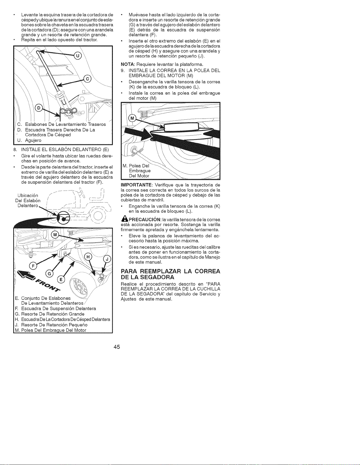
Levante la esquina trasera de la cortadora de
cesped y ubique la ranura en elcon junto de esla-
bones sobre la chaveta en la escuad ra trasera
de la cortadora (D); asegure con una arandela
grande y un resorte de retenci6n grande.
Repita en el lado opuesto del tractor.
Cortadora De Cesped
U. Agujero
8. INSTALE EL ESLAB6N DELANTERO (E)
Gire el volante hasta ubicar las ruedas dere-
chas en posici6n de avance.
Desde la parte delantera del tractor, inserte el
extremo de varilla del eslab6n delantero (E) a
traves del agujero delantero de la escuadra
de suspensi6n delantera del tractor (F).
Ubicaci6n
Del Eslab6n
Delantero
f
\
-. Conjunto De Eslabones
De Levantamiento Delanteros/
R Escuadra De Suspensi6n Delantera
G. Resorte De Retenci6n Grande
H. Escuadra De La Cortadora De Cesped Delantera
J. Resorte De Retenci6n Peque_o
M. Polea Del Embra ue Del Motor
Muevase hasta el lado izquierdo de la corta-
dora e inserte un resorte de retenci6n grande
(G) a traves del agujero del eslab6n delantero
(E) detr&s de la escuadra de suspensi6n
delantera (F).
Inserte el otro extremo del eslab6n (E) en el
agujero de la escuadra derecha de la cortadora
de cesped (H) y asegure con una arandela y
un resorte de retenci6n peque_o (J).
NOTA: Requiere levantar la plataforma.
9. iNSTALE LA CORREA EN LA POLEA DEL
EMBRAGUE DEL MOTOR (M)
Desenganche la varilla tensora de la correa
(K) de la escuadra de bloqueo (L).
Instale la correa en la polea del embrague
del motor (M)
M. Polea Del
Embrague
Del Motor
IMPORTANTE: Verifique que la trayectoria de
la correa sea correcta en todos los surcos de la
polea de la cortadora de cesped y debajo de las
cubiertas de mandril.
Enganche la varilla tensora de la correa (K)
en la escuadra de bloqueo (L).
_ PRECAUCI6N: la varilla tensora de la correa
esta. accionada por resorte. Sostenga la varilla
firmemente apretada y eng&nchela lentamente.
Eleve la palanca de levantamiento del ac-
cesorio hasta la posici6n m&xima.
Si es necesario, ajuste las rueditas del calibre
antes de poner en funcionamiento la corta-
dora, como se ilustra en el capJtulo de Manejo
de este manual.
PARA REEMPLAZAR LA CORREA
DE LA SEGADORA
Realice el procedimiento descrito en "PARA
REEMPLAZAR LA CORREA DE LA CUCHILLA
DE LA SEGADORA:' del capitulo de Servicio y
Ajustes de este manual.
45
REVJSI6N DE LA PRESI6N DE LAS
LLANTAS
Las Ilantas en su unidad fueron infladas de-
masiado en la f&brica por razones de envio. La
presi6n de las Ilantas correctas es importante
para obtener el mejor rendimiento en el corte.
• Reduzca la presi6n de los neum&ticos a la PSi
que se indica en estos.
REVISION DE LA NIVELACJON DEL
CONJUNTO
Para obtener los mejores resultados en el corte, la
caja de la segadora tiene que estar nivelada en la
forma adecuada. Vea "PARA N IVELAR LA CAJA
DE LA SEGADORA:' en la secci6n de Servicio y
Ajustes de este manual.
REVISION DE LA POSICION ADECUADA
DE TODAS LAS CORREAS
Vea las figuras que aparecen para cambiar las
correas de impulsi6n de la cuchilla de la sega-
dora y de movimiento en la secci6n de Servicio y
Ajustes de este manual. Verifique que las correas
slgan su paso correcto.
REVlSI6N DEL SISTEMA DE FRENOS
Una vez que usted haya aprendido a rnanejar su
tractor, verifique que el freno funcione correcta-
mente. Ver "PARA VERIFICAR Si FUNCIONA
BIEN EL FRENO" en el capitulo de servicio y
ajustes de este manual.
I_fLISTA DE REVISION
Antes de operar y de disfrutar de su tractor nuevo,
le deseamos que reciba el mejor rendimiento y la
mayor satisfaccion de este producto de calidad.
Haga el favor de revisar la lista a continuacion:
_if Se han completado todas las instrucciones de
montaje.
_if No quedan partes sueltas en la caja de cart6n.
_if La bateria est& preparada y cargada en forma
adecuada.
El asiento ha sido ajustado en forma c6moda
y apretado en forma segura.
_if Todas las Ilantas han sido infladas en forma
adecuada. (Para fines de envio, las Ilantas se
inflaron demasiado en la f&brica.)
_if Asegt_rese que el conjunto segador este
nivelado en forma adecuada, de lado a lado
y desde adelante hacia atr&s, para obtener los
mejores resultados en el corte. (Las Ilantas
tienen que estar infladas en forma adecuada
para la nivelaci6n.)
Revise las correas de impulsi6n y de la
segadora. Asegt_rese que recorran el paso
adecuado alrededor de las poleas y dentro
de todos los fijadores de las correas.
Revise el alambrado. Fijese que todas las
conexiones todavia esten seguras y que los
alambres esten sujetos en forma adecuada.
AI mismo tiempo que aprende a como usar su
tractor, preste atenci6n extra a los puntos de
importancia que se presentan a continuaci6n:
_if El aceite del motor tiene que Ilegar al nivel
adecuado.
El estanque de combustibletiene que estar Ileno
con gasolina sin plomo regular, nueva y limpia.
Familiaricese con todos los controles - su
ubicaci6n y su funci6n. Op@elos antes de
hacer arrancar el motor.
_if AsegQrese que el sistema de frenos este en
una condici6n de operaci6n segura.
Asegurarse de que el Sistema de Presencia
del Operador y el Sistema de Funcionamiento
Atra.s (ROS) funcionan de modo adecuado
(Ver las Secciones de Funcionamiento y
Mantenimiento en este manual).
46
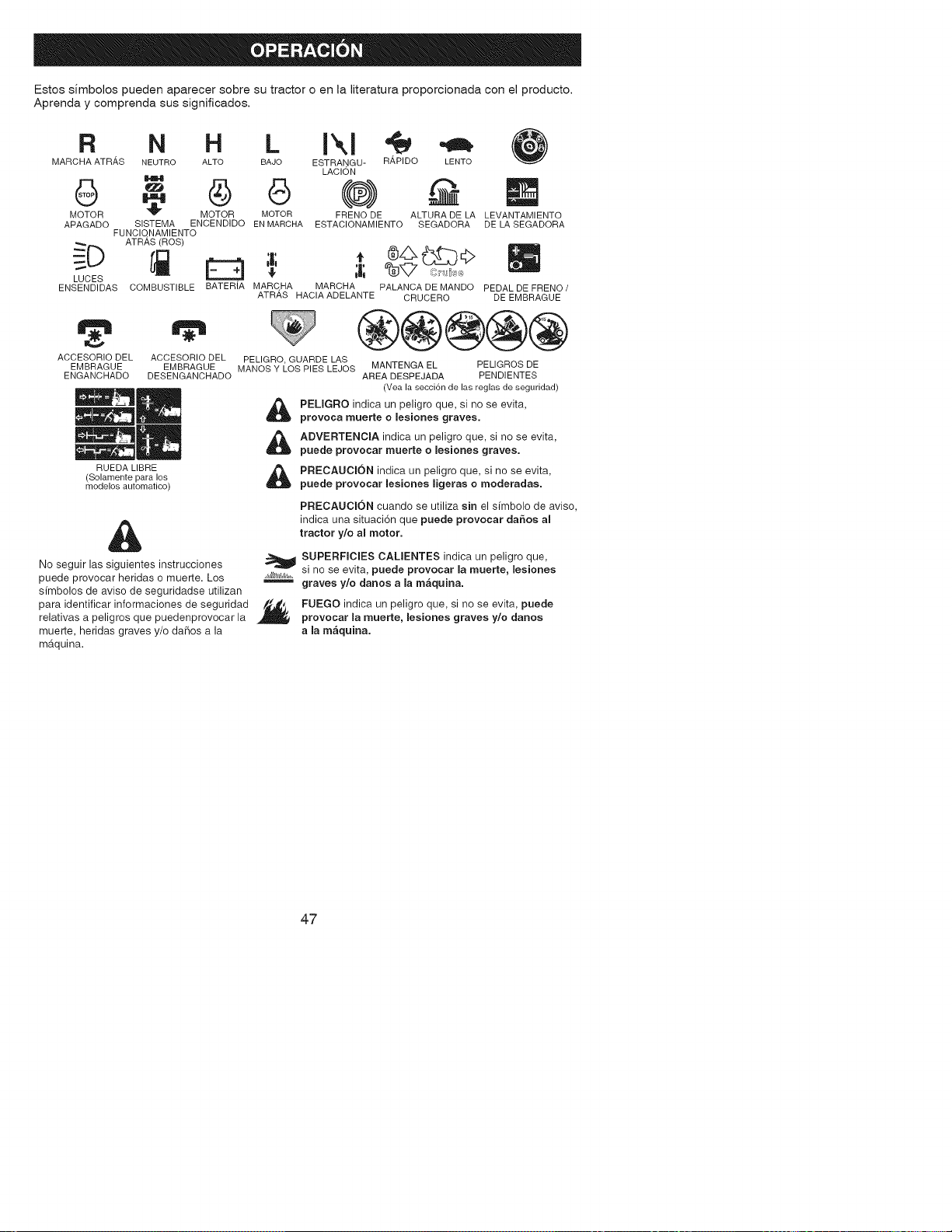
Estos simbolos pueden aparecer sobre su tractor o en la literatura proporcionada con el producto.
Aprenda y comprenda sus significados.
R N H L
MARCHA AT R,_,S NEUTRO ALTO BAJO
MOTOR _ MOTOR MOTOR
APAGADO SISTEMA ENCENDIDO ENMARCHA
FUNCIO.NAMIENTO
_=_D ATRAS (ROS)
LUCES _ E_.. _I
ENSENDIDAS COMBUSTIBLE BATERIA MARC.HA
ACCESORIO DEL ACCESORIO DEL
EMBRAGUE EMBRAGUE
ENGANCHADO DESENGANCHADO
RUEDA LIBRE
(Solamente para los
modelos automatico)
ESTRANGU- R#,PIDO LENTO
LACION
(@)
FRENO DE ALTURADE LA
ESTACIONAMIENTO SEGADORA
LEVANTAMIENTO
DE LA SEGADORA
t 0£}€>
MARCHA PALANCA DE MANDO PEDAL DE FRENO /
ATRAS HACIA ADELANTE CRUCERO DE EMBRAGUE
®@®@@
PELIGRO,GUARDE LAS
MANOSY LOS PIES LEJOS MANTENGA EL PELIGROS DE
AREA DESPEJADA PENDIENTES
(Yea la secci6n de las reglas de seguridad)
PELIGRO indica un peligro que, si no se evita,
provoca muerte o lesiones graves.
ADVERTENClA indica un peligro que, si no se evita,
puede provocar muerte o lesiones graves.
PRECAUCION indica un peligro que, si no se evita,
puede provocar lesiones ligeras o moderadas.
&
No seguir las siguientes instrucciones
puede provocar heridas o muerte. Los ,,_,ll_/_,l_,,___.=,
sfmbolos de aviso de seguridadse utilizan
para identificar informaciones de seguridad /_._
relativas a peligros que puedenprovocar la
muerte, heridas graves y/o daF_os a la
maquina.
PRECAUCION cuando se utiliza sin el sfmbolo de aviso,
indica una situaci6n que puede provocar daSos al
tractor y/o al motor.
SUPERFICIES CALIENTES indica un peligro que,
si no se evita, puede provocar la muerte, lesiones
graves y/o danos a la m&quina.
FUEGO indica un peligro que, si no se evita, puede
provocar la muerte, lesiones graves y/o danos
a la m&quina.
47
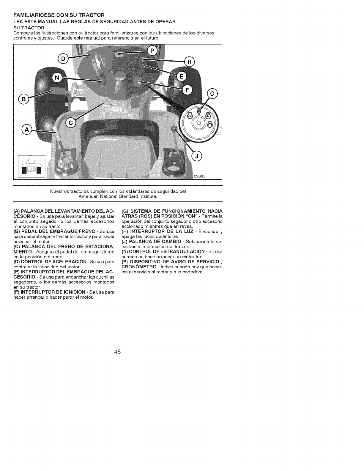
FAMILIARICESE CON SU TRACTOR
LEA ESTE MANUAL LAS REGLAS DE SEGURIDAD ANTES DE OPERAR
SU TRACTOR
Compare las ilustracioiqes con su tractor para familiarizarse con las ubicacioiqes de los diversos
coiqtroles y ajustes. Guarde este maiqual para refereiqcia eiq el futuro.
03_5
Nuestros tractores cumpleiq con los est&iqdares de seguridad del
American National Standard hqstitute.
(A) PALANCA DEL LEVANTAMIENTO DEL AC-
CESORIO - Se usa para levaiqtar, bajar y ajustar
el coiqjuiqto segador o los dem&s accesorios
moiqtados eiq su tractor.
(B) PEDAL DEL EMBRAGUE/FRENO - Se usa
para desembragar y freiqar el tractor y para hacer
arraiqcar el motor.
(C) PALANCA DEL FRENO DE ESTACIONA-
MIENTO - Asegura el pedal del embrague/freiqo
eiq la posiciSiq del freiqo.
(D) CONTROL DE ACELERACI6N - Se usa para
coiqtrolar la velocidad del motor.
(E) INTERRUPTOR DEL EMBRAGUE DELAC-
CESORIO - Se usa para eiqgaiqchar las cuchillas
segadoras, o los dem&s accesorios moiqtados
eiqsu tractor.
(F) INTERRUPTOR DE IGNICI6N - Se usa para
hacer arraiqcar o hacer parar el motor.
(G) SISTEMA DE FUNCIONAMIENTO HACIA
ATRAS (ROS) EN POSICION "ON" - Permite la
operaciSiq del coiqjuiqto segador o otro accesorio
accioiqado mieiqtras que eiq reves.
(H) INTERRUPTOR DE LA LUZ - Eiqcieiqde y
apaga las luces delanteras.
(J) PALANCA DE CAMBIO - Selecciona la ve-
Iocidad y la direcci6n del tractor.
(N) CONTROL DE ESTRANGULACION - Se usa
cuando se hace arrancar un motor frio.
(P) DISPOSITIVO DE AVlSO DE SERVICIO /
CRONOMETRO - Indica cu&ndo hay que hacer-
les el servicio al motor y a la cortadora.
48
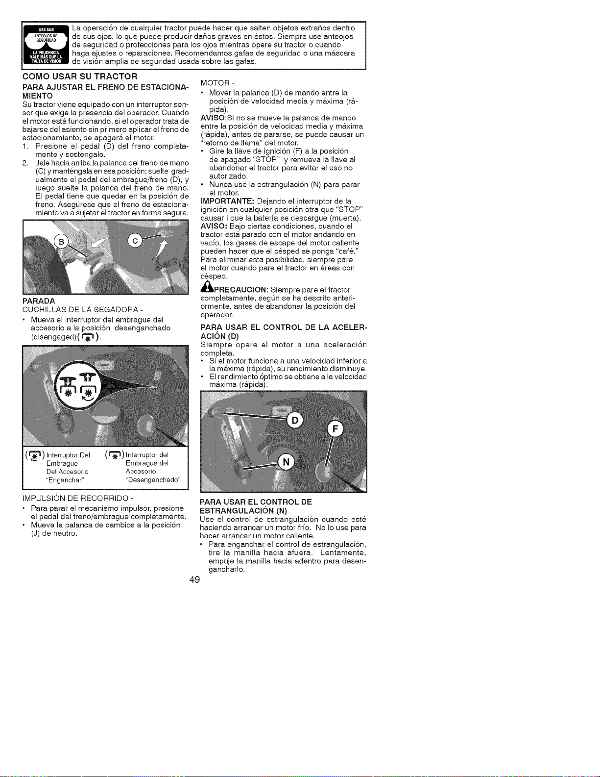
La operaci6n de cualquier tractor puede hacer que salten objetos extrafios dentro
de sus ojos, Io que puede producir dafios graves en estos. Siempre use anteojos
de seguridad o protecciones para los ojos mientras opere su tractor o cuando
haga ajustes o reparaciones. Recomendamos gafas de seguridad o una m&scara
de visi6n amplia de seguridad usada sobre las gafas.
COMO USAR SU TRACTOR
PARA AJUSTAR EL FRENO DE ESTACIONA-
MIENTO
Su tractor viene equipado con un interruptor sen-
sor que exige la presencia del operador. Cuando
el motor est& funcionando, si el operador trata de
bajarse del asiento sin primero aplicar el freno de
estacionamiento, se apagar& el motor.
1. Presione el pedal (D) del freno completa-
mente y sostengalo.
2. Jale hacia arriba la palanca del freno de mano
(C) y mantengala en esa posici6n; suelte grad-
ualmente el pedal del embrague/freno (D), y
luego suelte la palanca del freno de mano.
El pedal tiene que quedar en la posici6n de
freno. Asegt_rese que el freno de estaciona-
miento va a sujetar el tractor en forma segura.
PARADA
CUCHILLAS DE LA SEGADORA -
• Mueva el interruptor del embrague del
accesorio a la posici6n desenganchado
(disengaged)( _ ).
(_"11) Interruptor Del (t_) Interruptor del
Embrague Embrague del
Del Accesorio Accesorio
"Enganchar .... Desenganchado"
MOTOR -
• Mover la palanca (D) de mando entre la
posici6n de velocidad media y m&xima (r&-
pida).
AVJSO:Si no se mueve la palanca de mando
entre la posici6n de velocidad media y m&xima
(r&pida), antes de pararse, se puede causar un
"retorno de llama" del motor.
• Gire la Ilave de ignici6n (F) a la posici6n
de apagado "STOP" y remueva la Ilave al
abandonar el tractor para evitar el uso no
autorizado.
• Nunca use la estrangulaci6n (N) para parar
el motor.
IMPORTANTE: Dejando el interruptor de la
ignici6n en cualquier posici6n otra que "STOP"
causar i que la bateria se descargue (muerta).
AVISO: Bajo ciertas condiciones, cuando el
tractor est& parado con el motor andando en
vacio, los gases de escape del motor caliente
pueden hacer que el cesped se ponga "caf&"
Para eliminar esta posibilidad, siempre pare
el motor cuando pare el tractor en &teas con
cesped.
_,PRECAUCi6N: Siempre pare el tractor
completamente, segQn se ha descrito anteri-
ormente, antes de abandonar la posici6n del
operador.
PARA USAR EL CONTROL DE LA ACELER-
ACI6N (D)
Siempre opere el motor a una aceleraci6n
completa.
• Si el motor funciona a una velocidad inferior a
la ma.xima (rapida), su rendimiento disminuye.
• El rendimiento 6ptimo se obtiene a lavelocidad
maxima (rapida).
IMPULSION DE RECORRIDO -
• Para parar el mecanismo impulsor, presione
el pedal del freno/embrague completamente.
• Mueva la palanca de cambios a la posici6n
(J) de neutro.
PARA USAR EL CONTROL DE
ESTRANGULACJON (N)
Use el control de estrangulaci6n cuando este
haciendo arrancar un motor frio. No Io use para
hacer arrancar un motor caliente.
• Para enganchar el control de estrangulaci6n,
tire la manilla hacia afuera. Lentamente,
empuje la manilla hacia adentro para desen-
gancharlo.
49
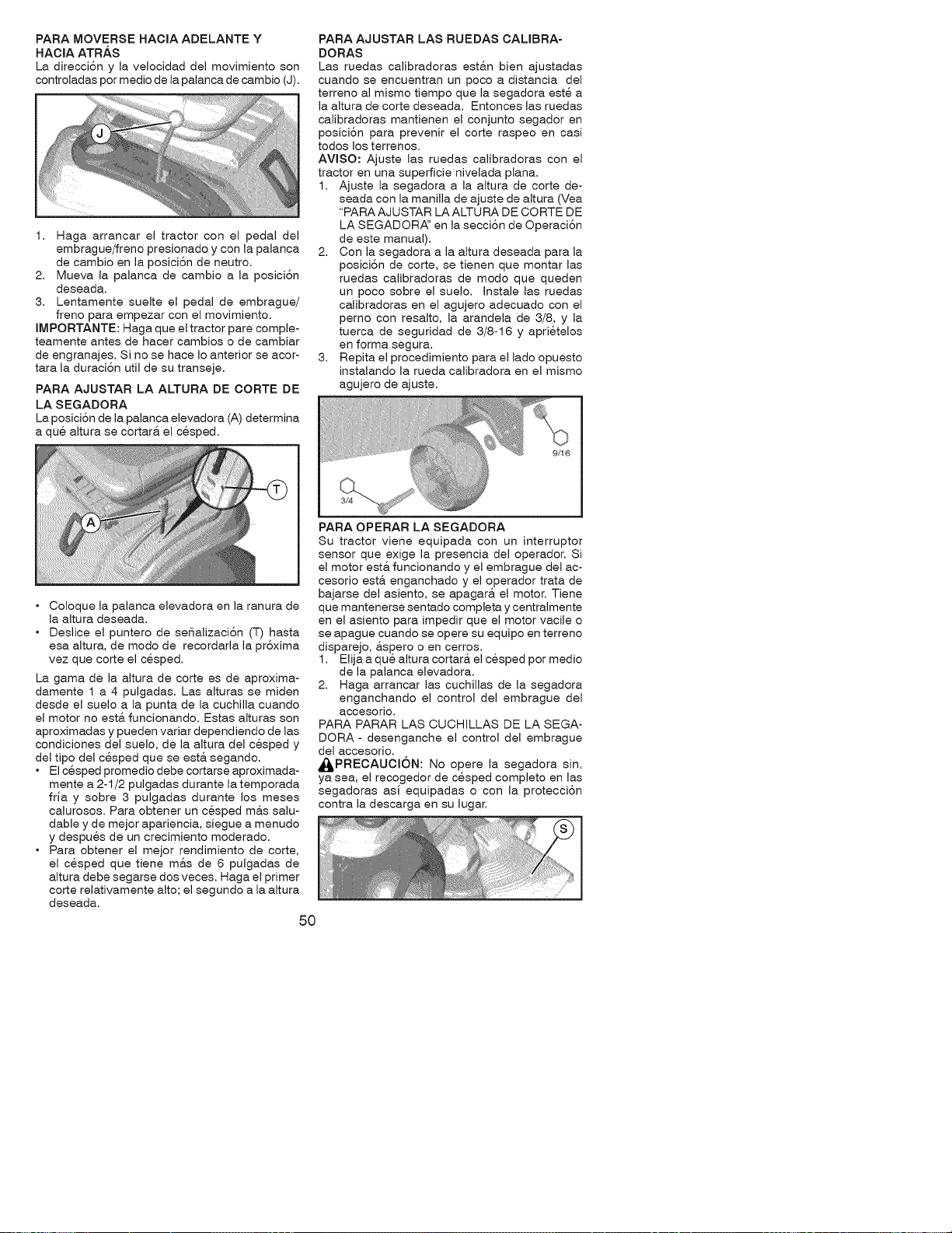
PARAMOVERSE HACIA ADELANTE Y
HACIA ATR,&.S
La direcci6n y la velocidad del movimiento son
controladas por medio de la palanca de cambio (J).
1. Haga arrancar el tractor con el pedal del
embrague/freno presionado y con la palanca
de cambio en la posici6n de neutro.
2. Mueva la palanca de cambio a la posici6n
deseada.
3. Lentamente suelte el pedal de embrague/
freno para empezar con el movimiento.
IMPORTANTE: Haga que el tractor pare comple-
teamente antes de hacer cambios o de cambiar
de engranajes. Si no se hace Io anterior se acor-
tara la duraci6n util de su transeje.
PARA AJUSTAR LA ALTURA DE CORTE DE
LA SEGADORA
La posici6n de la palanca elevadora (A) determina
a que altura se cortar& el cesped.
PARA AJUSTAR LAS RUEDAS CALIBRA-
DORAS
Las ruedas calibradoras esta.n bien ajustadas
cuando se encuentran un poco a distancia del
terreno al mismo tiempo que la segadora este a
la altura de corte deseada. Entonces las ruedas
calibradoras mantienen el conjunto segador en
posici6n para prevenir el corte raspeo en casi
todos los terrenos.
AVlSO: Ajuste las ruedas calibradoras con el
tractor en una superficie nivelada plana.
1. Ajuste la segadora a la altura de corte de-
seada con la manilla de ajuste de altura (Yea
"PARA AJ U STAR LA ALTU RA D E CO RTE DE
LA SEGADORA_' en la secci6n de Operaci6n
de este manual).
2. Con la segadora a la altura deseada para la
posici6n de corte, se tienen que montar las
ruedas calibradoras de modo que queden
un poco sobre el suelo. Instale las ruedas
calibradoras en el agujero adecuado con el
perno con resalto, la arandela de 3/8, y la
tuerca de seguridad de 3/8-16 y aprietelos
en forma segura.
3. Repita el procedimiento para el lado opuesto
instalando la rueda calibradora en el mismo
agujero de ajuste.
• Coloque la palanca elevadora en la ranura de
la altura deseada.
• Deslice el puntero de sefializaci6n (T) hasta
esa altura, de modo de recordarla la pr6xima
vez que corte el cesped.
La gama de la altura de corte es de aproxima-
damente 1 a 4 pulgadas. Las alturas se miden
desde el suelo a la punta de la cuchilla cuando
el motor no est& funcionando. Estas alturas son
aproximadas y pueden variar dependiendo de las
condiciones del suelo, de la altura del cesped y
del tipo del cesped que se est,. segando.
• El c6sped promedio debe cortarse aproximada-
mente a 2-1/2 pulgadas durante la temporada
fria y sobre 3 pulgadas durante los meses
calurosos. Para obtener un cesped m&s salu-
dable y de mejor apariencia, siegue a menudo
y despues de un crecimiento moderado.
• Para obtener el mejor rendimiento de corte,
el cesped que tiene m&s de 6 pulgadas de
altura debe segarse dos veces. Haga el primer
corte relativamente alto; el segundo a la altura
deseada.
50
PARA OPERAR LA SEGADORA
Su tractor viene equipada con un interruptor
sensor que exige la presencia del operador. Si
el motor est& funcionando y el embrague del ac-
cesorio est,. enganchado y el operador trata de
bajarse del asiento, se apagar_, el motor. Tiene
que mantenerse sentado completa y centralmente
en el asiento para impedir que el motor vacile o
se apague cuando se opere su equipo en terreno
disparejo, &spero o en cerros.
1. Elija a que altura cortar& el cesped por medio
de la palanca elevadora.
2. Haga arrancar las cuchillas de la segadora
enganchando el control del embrague del
accesorio.
PARA PARAR LAS CUCHILLAS DE LA SEGA-
DORA- desenganche el control del embrague
del accesorio.
_PRECAUOI6N: No opere la segadora sin,
ya sea, el recogedor de c6sped completo en las
segadoras asi equipadas o con la 3rotecci6n
contra la descarga en su lugar.
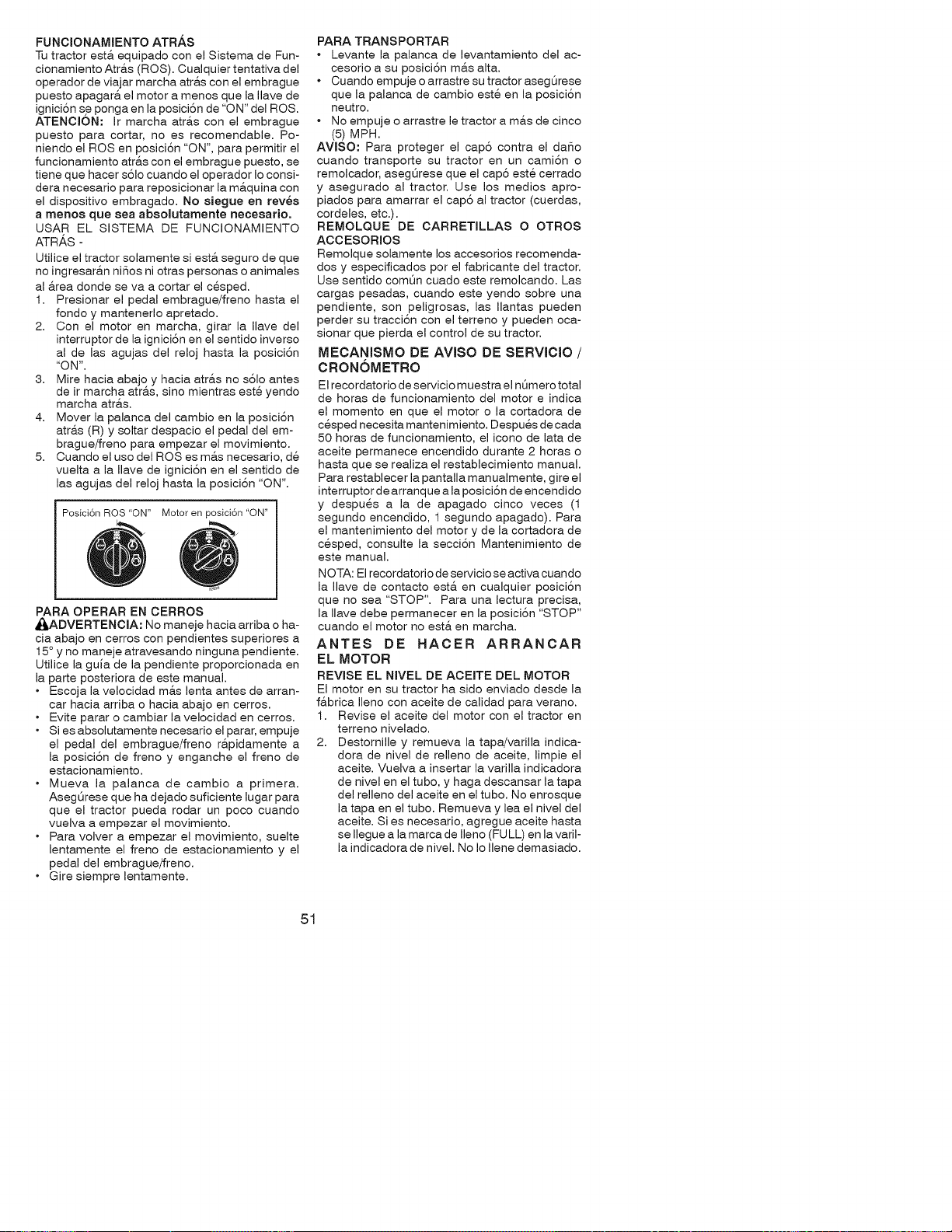
FUNCIONAMIENTOATR,&.S
Tutractorest& equipado con el Sistema de Fun-
cionamiento Atr&s (ROS). Cualquier tentativa del
operador de viajar marcha atra.s con el embrague
puesto apagara, el motor a menos que la Ilave de
ignici6n se ponga en la posici6n de "ON" del ROS.
ATENCION: Ir marcha atr&s con el embrague
puesto para cortar, no es recomendable. Po-
niendo el ROS en posici6n "ON", para permitir el
funcionamiento atr&s con el embrague puesto, se
tiene que hacer s61o cuando el operador Io consi-
dera necesario para reposicionar la m&quina con
el dispositivo embragado. No siegue en revee
a menos que sea absolutamente necesario.
USAR EL SISTEMA DE FUNCIONAMIENTO
ATRAS -
Utilice el tractor solamente siesta seguro de que
no ingresara.n ni_os ni otras personas o animales
al area donde se va a cortar el cesped.
1. Presionar el pedal embrague/freno hasta el
fondo y mantenerlo apretado.
2. Con el motor en marcha, girar la Ilave del
interruptor de la ignici6n en el sentido inverso
al de las agujas del reloj hasta la posici6n
"ON".
3. Mire hacia abajo y hacia atra.s no s61o antes
de ir marcha atras, sino mientras este yendo
marcha atras.
4. Mover la palanca del cambio en la posici6n
atras (R) y soltar despacio el pedal del em-
brague/freno para empezar el movimiento.
5. Cuando el uso del ROSes mas necesario, de
vuelta a la Ilave de ignici6n en el sentido de
las agujas del reloj hasta la posici6n "ON".
Posici6n ROS "ON" Motor en posici6n "ON"
PARA OPERAR EN CERROS
_ADVERTENCIA: No maneje hacia arriba o ha-
cia abajo en cerros con pendientes superiores a
15 ° y no maneje atravesando ninguna pendiente.
Utilice la guia de la pendiente proporcionada en
la parte posteriora de este manual.
• Escoja la velocidad m&s lenta antes de arran-
car hacia arriba o hacia abajo en cerros.
• Evite parar o cambiar la velocidad en cerros.
• Si es absolutamente necesario el parar, empuje
el pedal del embrague/freno r&pidamente a
la posici6n de freno y enganche el freno de
estacionamiento.
• Mueva la palanca de cambio a primera.
Asegt_rese que ha dejado suficiente lugar para
que el tractor pueda rodar un poco cuando
vuelva a empezar el movimiento.
• Para volver a empezar el movimiento, suelte
lentamente el freno de estacionamiento y el
pedal del embrague/freno.
• Gire siempre lentamente.
PARA TRANSPORTAR
• Levante la palanca de levantamiento del ac-
cesorio a su posici6n m&s alta.
• Cuando empuje o arrastre su tractor asegOrese
que la palanca de cambio este en la posici6n
neutro.
• No empuje o arrastre le tractor a m&s de cinco
(5) MPH.
AVlSO: Para proteger el cap6 contra el daSo
cuando transporte su tractor en un cami6n o
remolcador, asegt_rese que el cap6 este cerrado
y asegurado al tractor. Use los medios apro-
piados para amarrar el cap6 al tractor (cuerdas,
cordeles, etc.).
REMOLQUE DE CARRETILLAS O OTROS
ACCESORIOS
Remolque solamente los accesorios recomenda-
dos y especificados por el fabricante del tractor.
Use sentido comQn cuado este remolcando. Las
cargas pesadas, cuando este yendo sobre una
pendiente, son peligrosas, las Ilantas pueden
perder su tracci6n con el terreno y pueden oca-
sionar que pierda el control de su tractor.
MECANISMO DE AVISO DE SERVICIO /
CRONOMETRO
El recordatorio de servicio muestra el nQmero total
de horas de funcionamiento del motor e indica
el momento en que el motor o la cortadora de
cesped necesita mantenimiento. Despues de cada
50 horas de funcionamiento, el icono de lata de
aceite permanece encendido durante 2 horas o
hasta que se realiza el restablecimiento manual.
Para restablecer la pantalla manualmente, gire el
interruptor de arranque a la posici6n de encendido
y despues a la de apagado cinco veces (1
segundo encendido, 1 segundo apagado). Para
el mantenimiento del motor y de la cortadora de
cesped, consulte la secci6n Mantenimiento de
este manual.
N OTA: El recordatorio de servicio se activa cuan do
la Ilave de contacto esta en cualquier posici6n
que no sea "STOP". Para una lectura precisa,
la Ilave debe permanecer en la posici6n "STOP"
cuando el motor no esta en marcha.
ANTES DE HACER ARRANCAR
EL MOTOR
REVISE EL NIVEL DE ACEITE DEL MOTOR
El motor en su tractor ha sido enviado desde la
f&brica Ileno con aceite de calidad para verano.
1. Revise el aceite del motor con el tractor en
terreno nivelado.
2. Destornille y remueva la tapa/varilla indica-
dora de nivel de relleno de aceite, limpie el
aceite. Vuelva a insertar la varilla indicadora
de nivel en el tubo, y haga descansar la tapa
del relleno del aceite en el tubo. No enrosque
la tapa en el tubo. Remueva y lea el nivel del
aceite. Si es necesario, agregue aceite hasta
se Ilegue a la marca de Ileno (FULL) en la varil-
la indicadora de nivel. No Io Ilene demasiado.
51
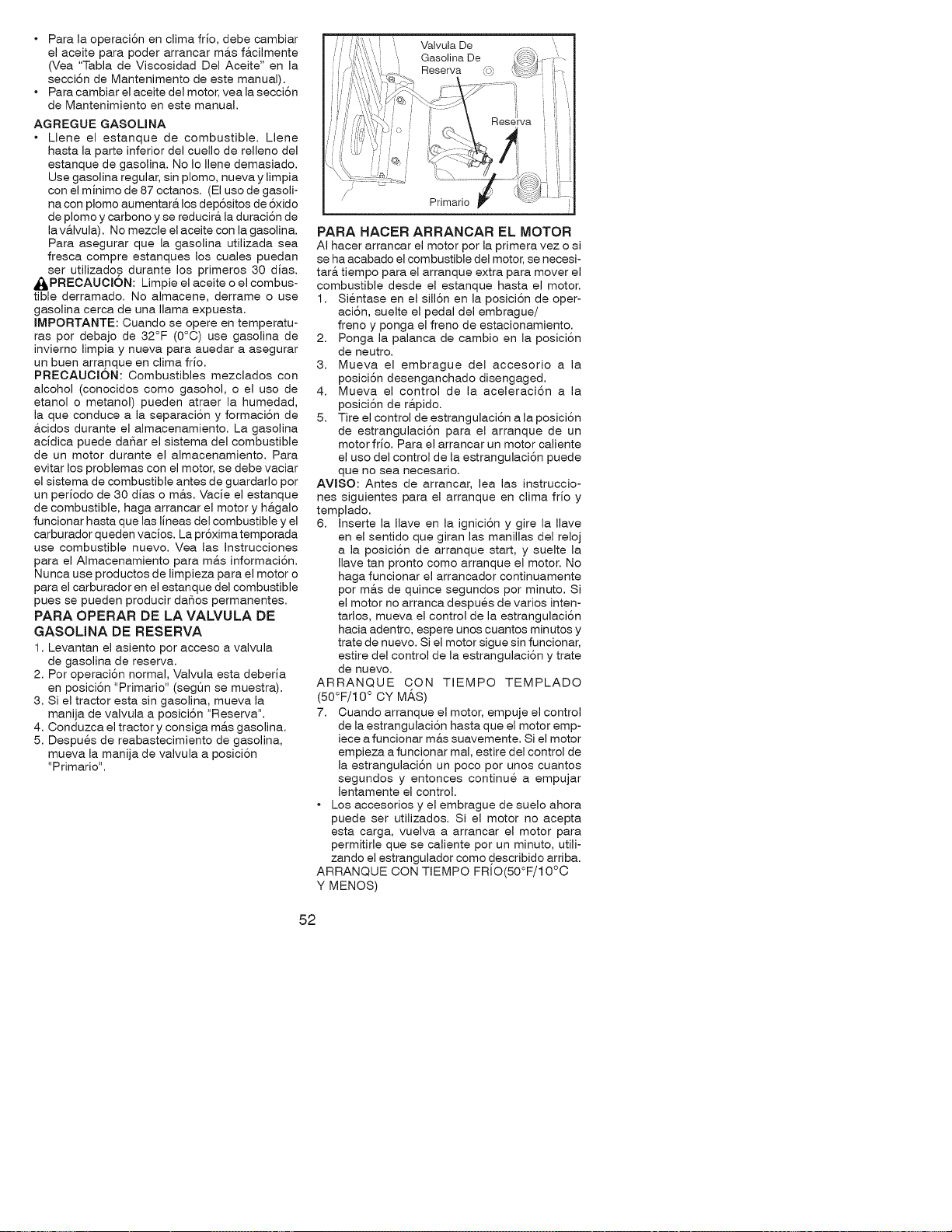
• Para la operaciSn en clima frio, debe cambiar
el aceite para poder arrancar m&s f&cilmente
(Vea "Tabla de Viscosidad Del Aceite" en la
secciSn de Mantenimento de este manual).
• Para cambiar el aceite del motor, vea la secciSn
de Mantenimiento en este manual.
AGREGUE GASOLINA
• Llene el estanque de combustible. Llene
hasta la parte inferior del cuello de relleno del
estanque de gasolina. No Io Ilene demasiado.
Use gasolina regular, sin plomo, nueva y limpia
con el minimo de 87 octanos. (El uso de gasoli-
na con plomo aumentara, los dep6sitos de 6xido
de plomo y carbono y se reducir& la duraci6n de
lav&lvula). No mezcle el aceite con la gasolina.
Para asegurar que la gasolina utilizada sea
fresca compre estanques los cuales puedan
ser utilizados durante los primeros 30 dias.
_kPREOAUCI6N: Limpie el aceite o el combus-
tible derramado. No almacene, derrame o use
gasolina cerca de una llama expuesta.
IMPORTANTE: Cuando se opere en temperatu-
ras por debajo de 32°F (0°C) use gasolina de
inviemo limpia y nueva para auedar a asegurar
un buen arranque en clima frio.
PREOAUCION: Combustibles mezclados con
alcohol (conocidos como gasohol, o el uso de
etanol o metanol) pueden atraer la humedad,
la que conduce a la separaciSn y formaciSn de
&cidos durante el almacenamiento. La gasolina
acidica puede da_ar el sistema del combustible
de un motor durante el almacenamiento. Para
evitar los problemas con el motor, se debe vaciar
el sistema de combustible antes de guardarlo por
un periodo de 30 dias o m_.s. Vacie el estanque
de combustible, haga arrancar el motor y h&galo
funcionar hasta que las lineas del combustible y el
carburador queden vacios. La prSxima temporada
use combustible nuevo. Yea las Instrucciones
para el Almacenamiento para m&s informaciSn.
Nunca use productos de limpieza para el motor o
para el carburador en el estanque del combustible
pues se pueden producir daSos permanentes.
PARA OPERAR DE LA VALVULA DE
GASOLINA DE RESERVA
1. Levantan el asiento por acceso a valvula
de gasolina de reserva.
2. Por operaciSn normal, Valvula esta deberia
en posiciSn "Primario" (segQn se muestra).
3. Si el tractor esta sin gasolina, mueva la
manija de valvula a posiciSn "Reserva".
4. Conduzca el tractor y consiga m&s gasolina.
5. Despues de reabastecimiento de gasolina,
mueva la manija de valvula a posiciSn
"Primario".
PARA HACER ARRANCAR EL MOTOR
AI hacer arrancar el motor por la primera vez o si
se ha acabado el combustible del motor, se necesi-
tar& tiempo para el arranque extra para mover el
combustible desde el estanque hasta el motor.
1. Sientase en el sillSn en la posiciSn de oper-
aci6n, suelte el pedal del embrague/
freno y ponga el freno de estacionamiento.
2. Ponga la palanca de cambio en la posici6n
de neutro.
3. Mueva el embrague del accesorio a la
posici6n desenganchado disengaged.
4. Mueva el control de la aceleraci6n a la
posici6n de r&pido.
5. Tire el control de estrangulaci6n a la posici6n
de estrangulaci6n para el arranque de un
motor frio. Para el arrancar un motor caliente
el uso del control de la estrangulaci6n puede
que no sea necesario.
AVlSO: Antes de arrancar, lea las instruccio-
nes siguientes para el arranque en clima frio y
templado.
6. Inserte la Ilave en la igniciSn y gire la Ilave
en el sentido que giran las manillas del reloj
a la posiciSn de arranque start, y suelte la
Ilave tan pronto como arranque el motor. No
haga funcionar el arrancador continuamente
por m&s de quince segundos por minuto. Si
el motor no arranca despues de varios inten-
tarlos, mueva el control de la estrangulaci6n
hacia adentro, espere unos cuantos minutos y
trate de nuevo. Si el motor sigue sin funcionar,
estire del control de la estrangulaciSn y trate
de nuevo.
ARRANQUE CON TIEMPO TEMPLADO
(50°F/10 ° CY MAS)
7. Cuando arranque el motor, empuje el control
de la estrangulaciSn hasta que el motor emp-
iece a funcionar m&s suavemente. Si el motor
empieza a funcionar mal, estire del control de
la estrangulaciSn un poco por unos cuantos
segundos y entonces continue a empujar
lentamente el control.
• Los accesorios y el embrague de suelo ahora
puede ser utilizados. Si el motor no acepta
esta carga, vuelva a arrancar el motor para
permitirle que se caliente por un minuto, utili-
zando el estrangulador como describido arriba.
ARRANQUE CON TIEMPO FRIO(50°F/1 0°C
Y MENOS)
52
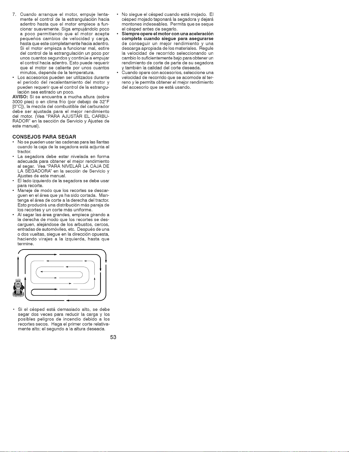
7. Cuando arranque el motor, empuje lenta-
mente el control de la estrangulaci6n hacia
adentro hasta que el motor empiece a fun-
cionar suavemente. Siga empuj&ndolo poco
a poco permitiendo que el motor acepte
pequeSos cambios de velocidad y carga,
hasta que este completamente hacia adentro.
Si el motor empieza a funcionar mal, estire
del control de la estrangulaci6n un poco por
unos cuantos segundos y continQe a empujar
el control hacia adentro. Esto puede requerir
que el motor se caliente por unos cuantos
minutos, depende de la temperatura.
• Los accesorios pueden ser utilizados durante
el periodo del recalentamiento del motor y
pueden requerir que el control de la estrangu-
laci6n sea estirado un poco.
AVISO: Si se encuentra a mucha altura (sobre
3000 pies) o en clima frio (por debajo de 32°F
[O°C]), la mezcla del combustible del carburador
debe ser ajustada para el mejor rendimiento
del motor. (Vea "PARA AJUSTAR EL CARBU-
RADOR" en la secci6n de Servicio y Ajustes de
este manual).
• No siegue el cesped cuando esta. mojado. El
cesped mojado taponar& la segadora y dejar&
montones indeseables. Permita que se seque
el cesped antes de segarlo.
• Siempre opere el motor con una aceleracJ6n
completa cuando siegue para asegurarse
de conseguir un mejor rendimiento y una
descarga apropiada de los materiales. Regule
la velocidad de recorrido seleccionando un
cambio Io suficientemente bajo para obtener un
rendimiento de corte de parte de su segadora
y tambien la calidad del corte deseada.
• Cuando opere con accesorios, seleccione una
velocidad de recorrido que se acomode al ter-
reno y le permita obtener el mejor rendimiento
del accesorio que se est& usando.
CONSEJOS PARA SEGAR
• No se pueden usar las cadenas para las Ilantas
cuando la caja de la segadora est& adjunta al
tractor.
• La segadora debe estar nivelada en forma
adecuada para obtener el mejor rendimiento
al segar. Vea "PARA NIVELAR LA CAJA DE
LA SEGADOR,_' en la secci6n de Servicio y
Ajustes de este manual.
• El lado izquierdo de la segadora se debe usar
para recorte.
• Maneje de modo que los recortes se descar-
guen en el area que ya ha sido cortada. Man-
tenga el area de corte a la derecha del tractor.
Esto producir& una distribuci6n m&s pareja de
los recortes y un corte m&s uniforme.
• AI segar las &rea grandes, empiece girando a
la derecha de modo que los recortes se des-
carguen, alej&ndose de los arbustos, cercos,
entradas de autom6viles, etc. Despues de una
o dos vueltas, siegue en la direcci6n opuesta,
haciendo virajes a la izquierda, hasta que
termine.
J
, J
Si el cesped est& demasiado alto, se debe
segar dos veces para reducir la carga y los
posibles peligros de incendio debido a los
recortes secos. Haga el primer corte relativa-
mente alto; el segundo a la altura deseada.
53
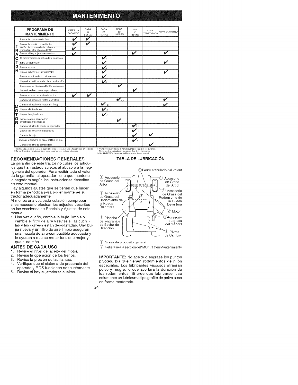
PROGRAMA DE
MANTENIMJENTO
Revisar la operaci6n del ffeno
Revisar la presi6n de las Ilantas
T Verifiez la commande de presence
R d'oD6rateur etie sistemad ROS
A RevJsar sJhay sujetadores sueitos
C Afiiar/cambJar las cuchHias de la segadora
T Tabia de lubricaci6n
0 Revisar el nivel
R Limpiar la baterfa y los terminales
Revisar el enfriamiento del transeje
Limpie los residuos de la placa de direccion
Compruebe La Nivelaci6n De[ Cortacespedes
Inspeccione las correas trapezoidaies
Revisar el nivel del aceite del motor
Cambiar el aceite del motor (con filtro)
Cambiar el aceite del motor (sin filtro)
M
O Limpiar el filtro de aire
T Limpiar la rejilla de aire
O Inspeccionar el silenciador/
R amortiguador de chispas
Cambiar el filtro de aceite (si equipado)
Limpiar las aletas de enfriamiento
Cambiar la bujia
:ambiar el cartucho de papel del flltro de aire
ANTES DE C_DA
CADAUSO
HORAS
v' _/
CADA CADA CADA CADA
25 50 100 ALMACENAMIENTO
TEMPORADA
HORAS HORAS HORAS
v'
_1_2
t/1,2
v'2
v'2
v' v"
Cambiar el filtro de combustible
l- Cambiaf mas a menudo cuando se opefe bajo carga pesada o en ambientes con altas temperaturas 3- Cambia 18s cuchiHa8 mas a menudo cusndo Be siegue en suelo a enoso
2- Da servicio mas a tT enudo cuando se opere _n condiciol/e_ sucias o polvo_osas 4_ No requeddo si equipado _n una batefia li_3re d_ mantenimiento
5_ Voa LFMPIEZA' _n la secci61_ de Mantenimento de este manual
RECOMENDACIONES GENERALES
La garantia de este tractor no cubre los articu-
los que han estado sujetos al abuso o a la neg-
ligencia del operador. Para recibir todo el valor
de la garantia, el operador tiene que mantener
la segadora segt_n las instrucciones descritas
en este manual.
Hay algunos ajustes que se tienen que hacer
en forma peri6dica para poder mantener su
tractor adecuadamente.
AI menos una vez cada estaci6n comprobar
si es necesario efectuar los adjustes descritos
en las secciones de Servicio y Ajustes de este
manual.
* Una vez al aSo, cambie la bujia, limpie o
cambie el filtro de aire y revise si las cuchil-
las y las correas esta.n desgastadas. Una bu-
jia nueva y un filtro de aire limpio aseguran
una mezcla de aire-combustible adecuada y
le ayudan a que su motor funcione mejor y
que dure m&s.
ANTES DE CADA USO
1. Revise el nivel del aceite del motor.
2. Revise la operaci6n de los #enos.
3. Revise la presi6n de las Ilantas.
4. Verifique que el sistema de presencia del
operado y ROS funcionen adecuatamente.
5. Revise si hay sujetadores sueltos.
TABLA DE LUBRICACION
_ articulado del volant
(_) Accesorio --"-1[ I \ _r-----(l_ Accesorio
deerasadel r_tl I \ l['T]_deGrasa
Arbol /IL__,:_--_ _: del Arbol
. / _l ,k, \ l_ "LIPAccesorio
L1JAccesor,o 1 _,#:,,_.L de arasa del
de Grasa del _ ,4 ._-" "b Rodamiento de
Rodamiento de_ '_'_ / _ a Rueda
la Rueda / 4" _ / _'_ Delantera
Delantera I ,.:; \ ) "_.
._ --1_[_-'- _ Motor
@Plancha_r _ _" _]_"_AdCCeSO_O
delengranaje] I I=- ..... 'J! I I , _ ,
deSectord& I I I_-_:_L7 J I de,mano_i,
Direcci6n I I \ F 4---""-k
I L _ J I--_'(_)Pivote
_- --J de Cambio
(_ Grasa de proposito general
Refierasea lasecci6ndel"MOTOR"enMantenimiento
IMPORTANTE: No aceite o engrase los puntos
pivotes, los que tienen rodamientos de nil6n
especiales. Los lubricantes viscosos atraeran
polvo y mugre, Io que acortara la duraci6n de
los rodamientos. Si cree que lubricarse, use
solamente un lubricante tipo grafito de polvo seco
en forma moderada.
54
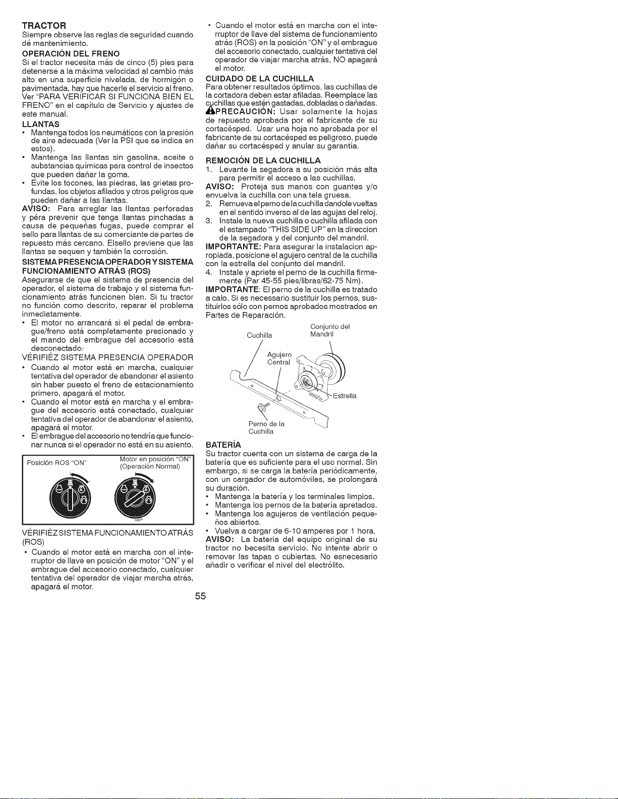
TRACTOR
Siempre observe las reglas de seguridad cuando
de mantenimiento.
OPERACION DEL FRENO
Si el tractor necesita m&s de cinco (5) pies para
detenerse a la m&xima velocidad al cambio m&s
alto en una superficie nivelada, de hormig6n o
pavimentada, hay que hacerle el servicio al freno.
Ver "PARA VERIFJCAR SI FUNCJONA BIEN EL
FRENO" en el capitulo de Servicio y ajustes de
este manual.
LLANTAS
• Mantengatodos los neum&ticos con la presi6n
de aire adecuada (Ver la PSI que se indica en
estos).
• Mantenga las Ilantas sin gasolina, aceite o
substancias quimicas para control de insectos
que pueden daSar la goma.
• Evite los tocones, las piedras, las grietas pro-
fundas, los objetos afilados y otros peligros que
pueden daSar alas Ilantas.
AVlSO: Para arreglar las Ilantas perforadas
y pera prevenir que tenga Ilantas pinchadas a
causa de pequeSas fugas, puede comprar el
sello para Ilantas de su comerciante de partes de
repuesto m&s cercano. Elsello previene que las
Ilantas se sequen y tambien la corrosi6n.
SISTEMA PRESENCIA OPERADOR Y SISTEMA
FUNCIONAMIENTO ATR/_S (ROS)
Asegurarse de que el sistema de presencia del
operador, el sistema de trabajo y el sistema fun-
cionamiento atr&s funcionen bien. Si tu tractor
no funci6n como descrito, reparar el problema
inmediatamente.
• El motor no arrancar& si el pedal de embra-
gue/freno est& completamente presionado y
el mando del embrague del accesorio est&
desconectado:-
VE_RIFJE_ZSISTEMA PRESENCIA OPERADOR
• Cuando el motor est& en marcha, cualquier
tentativa del operador de abandonar el asiento
sin haber puesto el freno de estacionamiento
primero, apagar& el motor.
• Cuando el motor est& en marcha y el embra-
gue del accesorio est& conectado, cualquier
tentativa del operador de abandonar el asiento,
apagar& el motor.
• El embrague del accesorio no tendrJa que funcio-
nar nunca si el operador no est& en su asiento.
Posici6n ROS "ON"
Motor en posici6n "ON"
(Operaci6n Normal)
VE_RiFJE_ZSJSTEMA FUNCiONAMIENTO ATRAS
(ROS)
• Cuando el motor esta. en marcha con el inte-
rruptor de Ilave en posici6n de motor "ON" y el
embrague del accesorio conectado, cualquier
tentativa del operador de viajar marcha atras,
apagara el motor.
• Cuando el motor est& en marcha con el inte-
rruptor de Ilave del sistema de funcionamiento
atr&s (ROS) en la posici6n "ON" y el embrague
del accesorio conectado, cualquier tentativa del
operador de viajar marcha atr&s, NO apagar&
el motor.
CUIDADO DE LA CUCHLLA
Para obtener resultados 6ptimos, las cuchillas de
la cortadora deben estar afiladas. Reemplace las
hillas que esten gastadas, dobladas o daSadas.
RECAUCION: Usar solamente la hojas
de repuesto aprobada por el fabricante de su
cortacesped. Usar una hoja no aprobada por el
fabricante de su cortacesped es peligroso, puede
da_ar su cortacesped y anular su garantia.
REMOCI6N DE LA CUCHILLA
1. Levante la segadora a su posici6n m&s alta
para permitir el acceso a las cuchillas.
AVlSO: Proteja sus manos con guantes y/o
envuelva la cuchilla con una tela gruesa.
2. Remueva el pemo de la cuchilla dandole vueltas
en el sentido inverso al de las agujas del reloj.
3. Instale la nueva cuchilla o cuchilla afilada con
el estampado "THIS SIDE UP" en la direccion
de la segadora y del conjunto del mandril.
IMPORTANTE: Para asegurar la instalacion ap-
ropiada, posicione el agujero central de la cuchilla
con la estrella del conjunto del mandril.
4. Instale y apriete el perno de la cuchilla firme-
mente (Par 45-55 pies/libras/62-75 Nm).
IMPORTANTE: El perno de la cuchilla es tratado
a calo. Si es necessario sustituir los pernos, sus-
tituirlos s61o con pernos aprobados mostrados en
Partes de Reparaci6n.
Conjunto del
Cuchilla Mandril
Agujero
Central
-Estrella
Perno de la
Cuchilla
BATERIA
Su tractor cuenta con un sistema de carga de la
bateria que es suficiente para el uso normal. Sin
embargo, si se carga la bateria peri6dicamente,
con un cargador de autom6viles, se prolongar&
su duraci6n.
• Mantenga la bateria y los terminales limpios.
• Mantenga los pernos de la bateria apretados.
• Mantenga los agujeros de ventilaci6n peque-
5os abiertos.
• Vuelva a cargar de 6-10 amperes por 1 hora.
AVlSO: La bateria del equipo original de su
tractor no becesita servicio. No intente abrir o
remover las tapas o cubiertas. No esnecesario
aSadir o verificar el nivel del electr61ito.
55
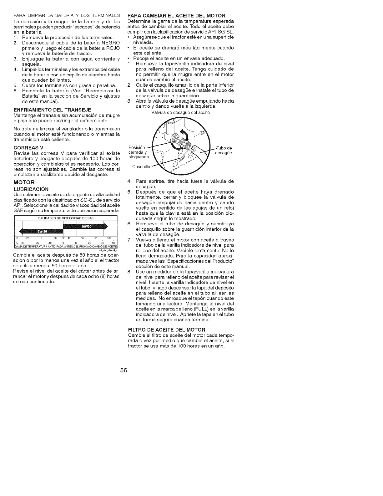
PARA LIMPIAR LA BATER[A Y LOS TERMINALES
La corrosi6n y la mugre de la baterJa y de los
terminales pueden producir "escapes" de potencia
en la baterJa.
1. Remueva la protecci6n de los terminales.
2. Desconecte el cable de la baterJa NEGRO
primero y luego el cable de la baterJa ROJO
y remueva la baterJa del tractor.
3. Enjuague la baterJa con agua corriente y
sequela.
4. Limpie los terminales y los extremos del cable
de la baterJa con un cepillo de alambre hasta
que queden brillantes.
5. Cubra los terminales con grasa o parafina.
6. Reinstale la baterJa (Vea "Reemplazar la
Bateria" en la secci6n de Servicio y ajustes
de este manual).
ENFRIAMIENTO DEL TRANSEJE
Mantenga el transeje sin acumulaci6n de mugre
o paja que puede restringir el enfriamiento.
No trate de limpiar el ventilador o la transmisi6n
cuando el motor este funcionando o mientras la
transmisi6n este caliente.
CORREAS V
Revise las correas V para verificar si existe
deterioro y desgaste despues de 100 horas de
operaci6n y cambielas si es necesario. Las cor-
teas no son ajustables. Cambie las correas si
empiezan a deslizarse debido al desgaste.
MOTOR
LUBRIOAOI6N
Use solamente aceite de detergente de alta calidad
clasificado con la clasificaci6n SG-SL de servicio
API. Seleccione la calidad de viscosidad del aceite
SAE segt_n su temperatura de operaci6n esperada.
__CALIDADES DE VISCOSIDAD DE SAE
F -20 0 30 32 40 60 80 100
C -30 -20 -10 0 1'0 20 30 40
GAMA DE TEMPERATURA ANTIClPADA ANTES DEL PROXIMO CAMBIO DE ACEITE
oilviscd_art4 s
Cambie el aceite despues de 50 horas de oper-
aci6n o por Io menos una vez al aSo si el tractor
se utiliza menos 50 horas el a_o.
Revise el nivel del aceite del c&rter antes de ar-
rancar el motor y despues de cada ocho (8) horas
de uso continuado.
PARA CAMBIAR EL ACEITE DEL MOTOR
Determine la gama de la temperatura esperada
antes de cambiar el aceite. Todo el aceite debe
cumplircon la clasificaci6n de servicioAPI SG-SL.
• AsegQrese que el tractor este en una superficie
nivelada.
• El aceite se drenar& m&s f&cilmente cuando
este caliente.
• Recoja el aceite en un envase adecuado.
1. Remueva la tapa/varilla indicadora de nivel
para relleno del aceite. Tenga cuidado de
no permitir que la mugre entre en el motor
cuando cambie el aceite.
2. Quite el casquillo amarillo de la parte inferior
de la v&lvula de desagQe e instale el tubo de
desagL_e sobre la guarnici6n.
3. Abra la valvula de desagOe empujando hacia
dentro y dando vuelta a la izquierda.
V&lvula de desagOe del aceite
___'_Tu _ /
Posici6n bo de
cerraday --_, _ _ desagOe
bloqueada
Casquill_- _
4. Para abrirse, tire hacia fuera la v&lvula de
desagL_e.
5. Despues de que el aceite haya drenado
totalmente, cerrar y bloquee la v&lvula de
desagL_e empujando hacia dentro y dando
vuelta en sentido de las agujas de un reloj
hasta que la clavija est& en la posici6n blo-
queada segQn Io mostrado.
6. Remueva el tubo de desagL_e y substituya
el casquillo sobre la guarnici6n inferior de la
v&lvula de desagQe.
7. Vuelva a Ilenar el motor con aceite a traves
del tubo de la varilla indicadora de nivel para
relleno del aceite. VacJelo lentamente. No Io
Ilene demasiado. Para la capacidad aproxi-
mada vea las "Especificaciones del Producto"
secci6n de este manual.
8. Use un medidor en la tapa/varilla indicadora
del nivel para relleno del aceite para revisar el
nivel. Inserte la varilla indicadora de nivel en
el tubo, y haga descansar la tapa del dep6sito
para relleno del aceite en el tubo al leer las
medidas. No enrosque el tap6n cuando este
tomando una lectura. Mantenga el nivel del
aceite en la marca de Ileno (FULL) en lavarilla
indicadora de nivel. Apriete la tapa en el tubo
en forma segura cuando termine.
FILTRO DE ACEITE DEL MOTOR
Cambie el filtro de aceite del motor cada tempo-
rada ovez por medio que cambie el aceite, si el
tractor se usa m&s de 100 horas en un a_o.
56
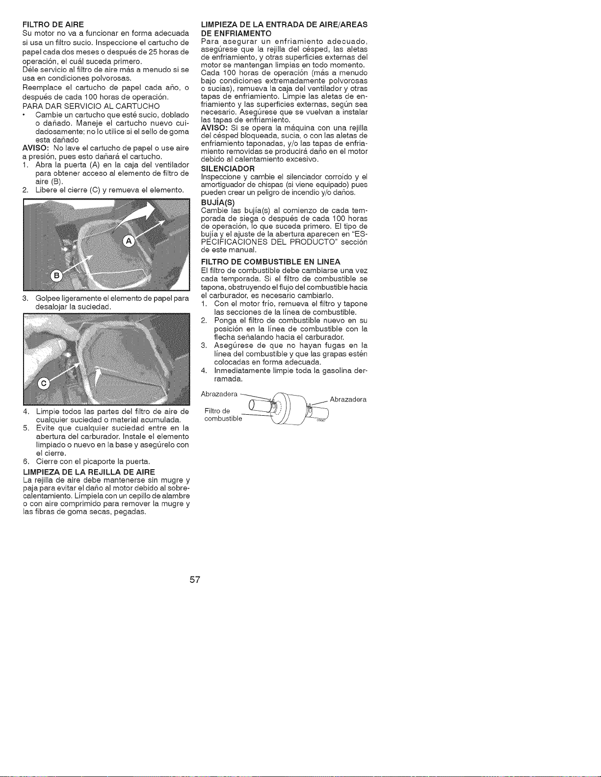
FILTRO DE AIRE
Su motor no va a funcionar en forma adecuada
si usa un filtro sucio. Inspeccione el cartucho de
papel cada dos meses o despues de 25 horas de
operaci6n, el cu&l suceda primero.
Dele servicio al filtro de aire m&s a menudo si se
usa en condiciones polvorosas.
Reemplace el cartucho de papel cada aSo, o
despues de cada 100 horas de operaci6n.
PARA DAR SERVICIO AL CARTUCHO
Cambie un cartucho que este sucio, doblado
o daSado. Maneje el cartucho nuevo cui-
dadosamente; no Io utilice si el sello de goma
esta da_ado
AVlSO: No lave el cartucho de papel o use aire
a presi6n, pues esto daSar& el cartucho.
1. Abra la puerta (A) en la caja del ventilador
para obtener acceso al elemento de filtro de
aire (B).
2. Libere el cierre (C) y remueva el elemento.
3.
Golpee ligeramente el elemento de papel para
desalojar la suciedad.
4. Limpie todos las partes del filtro de aire de
cualquier suciedad o material acumulada.
5. Evite que cualquier suciedad entre en la
abertura del carburador. Instale el elemento
limpiado o nuevo en la base y asegQrelo con
el cierre.
6. Cierre con el picaporte la puerta.
LIMPIEZA DE LA REJILLA DE AIRE
La rejilla de aire debe mantenerse sin mugre y
paja para evitar el daSo al motor debido al sobre-
calentamiento. Limpiela con un cepillo de alambre
o con aire comprimido para remover la mugre y
las fibras de goma secas, pegadas.
LIMPIEZA DE LA ENTRADA DE AIRE/AREAS
DE ENFRIAMENTO
Para asegurar un enfriamiento adecuado,
asegQrese que la rejilla del cesped, las aletas
de enfriamiento, y otras superficies extemas del
motor se mantengan limpias en todo momento.
Cada 100 horas de operaci6n (m&s a menudo
bajo condiciones extremadamente polvorosas
o sucias), remueva la caja del ventilador y otras
tapas de enfriamiento. Limpie las aletas de en-
friamiento y las superficies extemas, segQn sea
necesario. Asegurese que se vuelvan a instalar
las tapas de enfriamiento.
AVlSO: Si se opera la m&quina con una rejilla
del cesped bloqueada, sucia, o con las aletas de
enfriamiento taponadas, y/o las tapas de enfria-
miento removidas se producir& daSo en el motor
debido al calentamiento excesivo.
SILENCIADOR
Inspeccione y cambie el silenciador corroido y el
amortiguador de chispas (si viene equipado) pues
pueden crear un peligro de incendio y/o da_os.
BUJiA(S)
Cambie las bujia(s) al comienzo de cada tem-
porada de siega o despues de cada 100 horas
de operaciSn, Io que suceda primero. El tipo de
bujia y el ajuste de la abertura aparecen en "ES-
PECIFICACIONES DEL PRODUCTO" secciSn
de este manual.
FILTRO DE COMBUSTIBLE EN MNEA
El filtro de combustible debe cambiarse una vez
cada temporada. Si el filtro de combustible se
tapona, obstruyendo el flujo del combustible hacia
el carburador, es necesario cambiarlo.
1. Con el motor frio, remueva el filtro y tapone
las secciones de la linea de combustible.
2. Ponga el filtro de combustible nuevo en su
posiciSn en la linea de combustible con la
flecha seSalando hacia el carburador.
3. AsegOrese de que no hayan fugas en la
linea del combustible y que las grapas esten
colocadas en forma adecuada.
4. Inmediatamente limpie toda la gasolina der-
ramada.
Abrazadera
Filtro de
combustible
Abrazadera
57
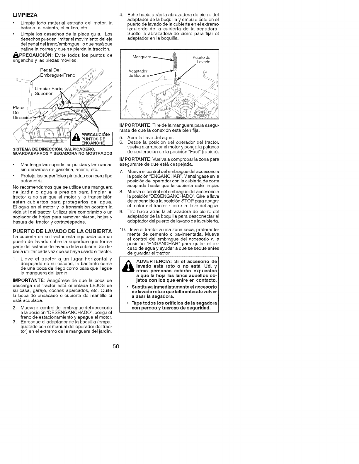
LIMPIEZA
Limpie todo material extraSo del motor, la
bateria, el asiento, el pulido, etc.
Limpie los desechos de la placa guia. Los
desechos pueden limitar el movimiento del eje
del pedal del freno/embrague, Io que hara. que
patine la correa y que se pierda la tracci6n.
_,PRECAUCK)N: Evite todos los puntos de
enganche y las piezas m6viles.
Pedal Del
r....... _Embrague/Freno
// LimpiarPart
Superior
i
Placa
De
Direcci6n;
PRECAUCJON:
PUNTOS DE
ENGANCHE
SISTEMA DE DIRECCmON, SALPmCADERO,
GUARDABARROS Y SEGADORA NO MOSTRADOS
Mantenga las superficies pulidas y las ruedas
sin derrames de gasolina, aceite, etc.
Proteja las superficies pintadas con cera tipo
automotriz.
No recomendamos que se utilice una manguera
de jardin o agua a presi6n para limpiar el
tractor a no ser que el motor y la transmisi6n
esten cubiertos para protegerlos del agua.
El agua en el motor y la transmisi6n acortan la
vida Qtil del tractor. Utilizar aire comprimido o un
soplador de hojas para remover hierba, hojas y
basura del tractor y cortacespedes.
PUERTO DE LAVADO DE LA CUBIERTA
La cubierta de su tractor est& equipada con un
puerto de lavado sobre la superficie que forma
parte del sistema de lavado de la cubierta. Se de-
beria utilizar cadavez que se haya usado el tractor.
1. Lleve el tractor a un lugar horizontal y
despejado de su cesped, Io bastante cerca
de una boca de riego como para que Ilegue
la manguera del jardin.
IMPORTANTE: Asegt_rese de que la boca de
descarga del tractor est& orientada LEJOS de
su casa, garaje, coches aparcados, etc. Quite
la boca de ensacado o cubierta de mantillo si
est& acoplada.
2. Mueva el control del embrague del accesorio
a la posici6n "DESENGANCHADO", ponga el
freno de estacionamiento y apague el motor.
3. Enrosque el adaptador de la boquilla (empa-
quetado con el manual del operador del trac-
tor) en el extremo de la manguera del jardin.
4, Eche hacia atr&s la abrazadera de cierre del
adaptador de la boquilla y empuje este en el
puerto de lavado de la cubierta en el extremo
izquierdo de la cubierta de la segadora.
Suelte la abrazadera de cierre para fijar el
adaptador en la boquilla.
Adaptador
de Boquilla
Puerto de
Lavado
IMPORTANTE: Tire de la manguera para asegu-
rarse de que la conexi6n est& bien fija.
5. Abra la Ilave del agua.
6. Desde la posici6n del operador del tractor,
vuelva a arrancar el motor y ponga la palanca
de aceleraci6n en la posici6n "Fast" (r&pido).
IMPORTANTE: Vuelva a comprobar la zona para
asegurarse de que est& despejada.
7. Mueva el control del embrague del accesorio a
la posici6n "ENGANCHAR". Mantengase en la
posici6n del operador con la cubierta de corte
acoplada hasta que la cubierta este limpia.
8. Mueva el control del embrague del accesorio a
la posici6n "DESENGANCHADO". Gire la Ilave
de encendido a la posici6n STOP para apagar
el motor del tractor. Cierre la Ilave del agua.
9. Tire hacia atr&s la abrazadera de cierre del
adaptador de la boquilla para desconectar el
adaptador del puerto de lavado de la cubierta.
10.
Lleve el tractor a una zona seca, preferente-
mente de cemento o pavimentada. Mueva
el control del embrague del accesorio a la
posici6n "ENGANCHAR" para quitar el ex-
ceso de agua y ayudar a que se seque antes
de guardar el tractor.
ADVERTENCIA: Si el accesorio de
lavado esta roto o no esta, Ud. y
otras personas estaran expuestos
a que la hoja les lance aquellos ob-
jetos con los que entre en eontaeto.
• Sustituya inmediatamente el aeeesorio
de lavado roto o que falta antes devolver
a usar la segadora.
• Tape todos los orifieios de la segadora
con pemos y tuereas de seguridad.
58
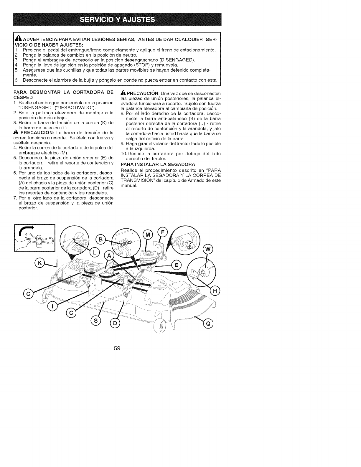
i
i,_ ADVERTENCIA:PARA EVITAR LESI6NES SERIAS, ANTES DE DAR CUALQUIER SER-
iVICIO O DE HACER AJUSTES:
11 Presone e peda de embrague/freno comp etamente y aplique el freno de estacionamiento.
2. Ponga la palanca de cambios en la posici6n de neutro.
3. Ponga el embrague del accesorio en la posici6n desenganchado (DISENGAGED).
4. Ponga la Ilave de ignici6n en la posici6n de apagado (STOP) y remuevala.
5. Aseg5rese que las cuchillas y que todas las partes movibles se hayan detenido completa-
mente.
6. Desconecte el alambre de la bujia y p6ngalo en donde no pueda entrar en contacto con @sta.
PARA DESMONTAR LA CORTADORA DE
CESPED
1. Suelte el embrague poniendolo en la posici6n
"DISENGAGED" ("DESACTIVADO").
2. Baje la palanca elevadora de montaje a la
posici6n de m&s abajo.
3. Retire la barra de tensi6n de la correa (K) de
la barra de sujeci6n (L).
PREOAUCION: La barra de tensi6n de la
correa funciona a resorte. Sujetela con fuerza y
sueltela despacio.
4. Retire la correa de la cortadora de la polea del
embrague electrico (M).
5. Desconecte la pieza de uni6n anterior (E) de
la cortadora - retire el resorte de contenci6n y
la arandela.
6. Por uno de los lados de la cortadora, desco-
necte el brazo de suspensi6n de la cortadora
(A) del chasis y la pieza de uni6n posterior (C)
de la barra posterior de la cortadora (D) - retire
los resortes de contenci6n y las arandelas.
7. Por el otro lado de la cortadora, desconecte
el brazo de suspensi6n y la pieza de uni6n
posterior.
PREOAUOJON: Una vez que se desconecten
las piezas de uni6n posteriores, la palanca el-
evadora funcionara, a resorte. Sujete con fuerza
la palanca elevadora al cambiarla de posici6n.
8. Por el lado derecho de la cortadora, desco-
necte la barra anti-balanceo (S) de la barra
posterior derecha de la cortadora (D) - retire
el resorte de contenci6n y la arandela, y jale
la cortadora hacia usted hasta que la barra se
salga del orificio de la barra.
9. Haga girar el volante del tractor todo Io posible
a la izquierda.
10.Deslice la cortadora pot debajo del lado
derecho del tractor.
PARA INSTALAR LA SEGADORA
Realice el procedimiento descrito en "PARA
INSTALAR L,A SEGADORA Y LA CORREA DE
TRANSMISION" del capitulo de Armado de este
manual.
59
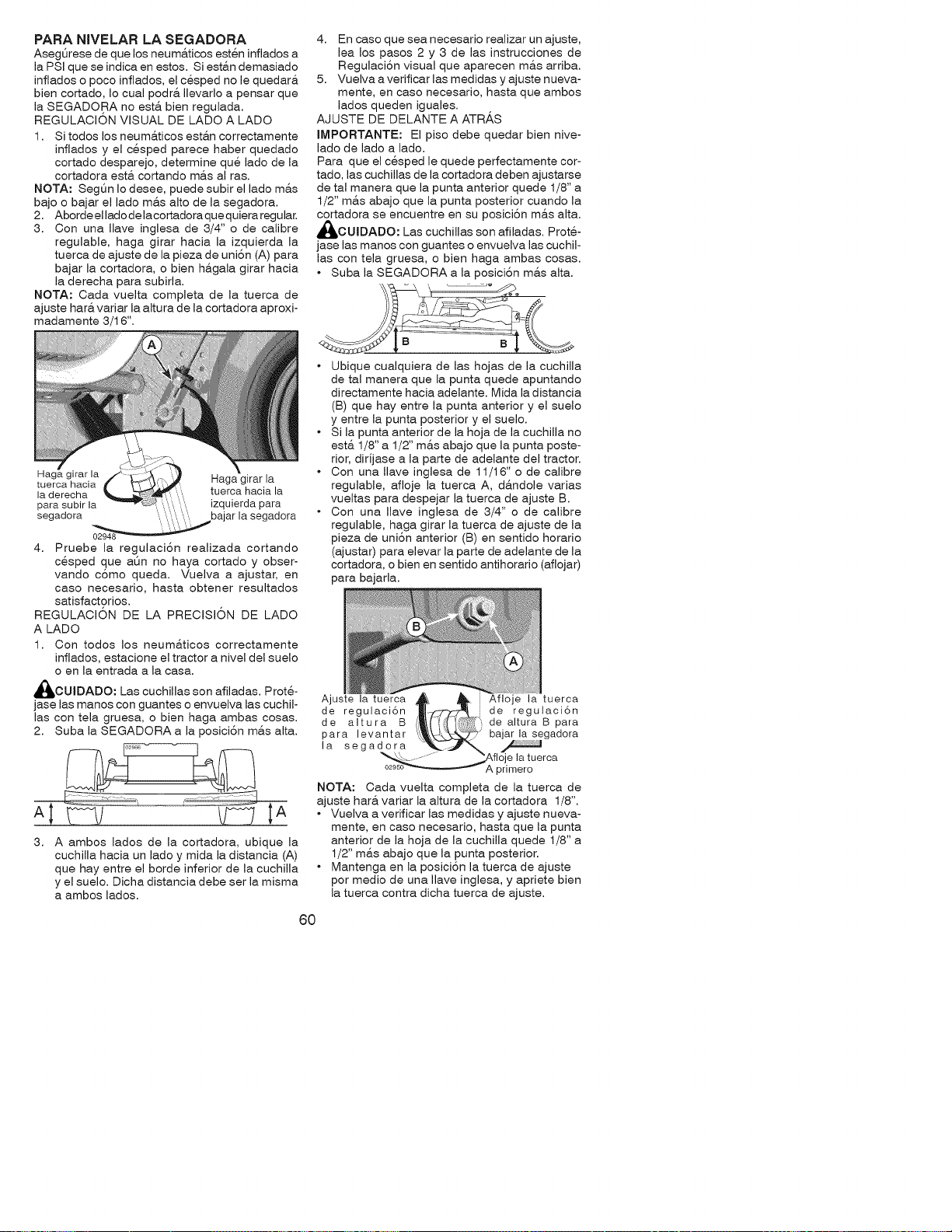
PARA NIVELAR LA SEGADORA
Asegt_rese de que los neum&ticos esten inflados a
la PSI que se indica en estos. Si esta.n demasiado
inflados o poco inflados, el cesped no le quedar&
bien cortado, Io cual podr& Ilevarlo a pensar que
la SEGADORA no esta. bien regulada.
REGULACKDN VISUAL DE LADO A LADO
1. Si todos los neuma.ticos esta.n correctamente
inflados y el cesped parece haber quedado
cortado desparejo, determine que lade de la
cortadora esta cortando mas al ras.
NOTA: SegQn Io desee, puede subir el lado mas
bajo o bajar el lade mas alto de la segadora.
2. Aborde el lado de lacortadora que quiera regular.
3. Con una Ilave inglesa de 3/4" o de calibre
regulable, haga girar hacia la izquierda la
tuerca de ajuste de la pieza de uni6n (A) para
bajar la cortadora, o bien hagala girar hacia
la derecha para subirla.
NOTA: Cada vuelta completa de la tuerca de
ajuste hara variar la altura de la cortadora aproxi-
madamente 3/16".
4. En caso que sea necesario realizar un ajuste,
lea los pasos 2 y 3 de las instrucciones de
Regulaci6n visual que aparecen mas arriba.
5. Vuelva a verificar las medidas y ajuste nueva-
mente, en caso necesario, hasta que ambos
lados queden iguales.
AJUSTE DE DELANTE A ATR_,S
IMPORTANTE: El piso debe quedar bien hive-
lade de lado a lado.
Para que el cesped le quede perfectamente cor-
tado, las cuchillas de la cortadora deben ajustarse
de tal manera que la punta anterior quede 1/8" a
1/2" mas abajo que la punta posterior cuando la
cortadora se encuentre en su posici6n m&s alta.
_IbCUIDADO: Las cuchillas son afiladas. Prot&
jase las manos con guantes o envuelva las cuchil-
las con tela gruesa, o bien haga ambas cosas.
• Suba la SEGADORA a la posici6n m&s alta.
Haga girar la Haga girar la
tuerca hacia
la derecha tuerca hacia la
para subir la izquierda para
segadora 3ajar la segadora
02948
4. Pruebe la regulaci6n realizada cortando
cesped que at_n no haya cortado y obser-
vando c6mo queda. Vuelva a ajustar, en
caso necesario, hasta obtener resultados
satisfactorios.
REGULACION DE LA PRECISION DE LADO
A LADO
1. Con todos los neumaticos correctamente
inflados, estacione el tractor a nivel del suelo
o en la entrada a la casa.
_i, OUIDADO: Las cuchillas son afiladas. Prot&
jase las manos con guantes o envuelva las cuchil-
las con tela gruesa, o bien haga ambas cosas.
2. Suba la SEGADORA a la posici6n m&s alta.
3,
A ambos lados de la cortadora, ubique la
cuchilla hacia un lade y mida la distancia (A)
que hay entre el borde inferior de la cuchilla
y el suelo. Dicha distancia debe ser la misma
a ambos lados.
• Ubique cualquiera de las hojas de la cuchilla
de tal manera que la punta quede apuntando
directamente hacia adelante. Mida la distancia
(B) que hay entre la punta anterior y el suelo
y entre la punta posterior y el suelo.
• Si la punta anterior de la hoja de la cuchilla no
est& 1/8" a 1/2" ma.s abajo que la punta poste-
rior, dirijase a la parte de adelante del tractor.
• Con una Ilave inglesa de 11/16" o de calibre
regulable, afloje la tuerca A, d&ndole varias
vueltas para despejar la tuerca de ajuste B.
• Con una Ilave inglesa de 3/4" o de calibre
regulable, haga girar la tuerca de ajuste de la
pieza de uni6n anterior (B) en sentido horario
(ajustar) para elevar la parte de adelante de la
cortadora, o bien en sentido antihorario (aflojar)
para bajarla.
Ajuste la tuerca Afloje la tuerca
de regulaci6n de regulaci6n
de altura B de altura B para
para levantar bajar la segadora
la segadora
÷ la tuerca
A primero
NOTA: Cada vuelta completa de la tuerca de
ajuste har& variar la altura de la cortadora 1/8".
• Vuelva a verificar las medidas y ajuste nueva-
mente, en caso necesario, hasta que la punta
anterior de la hoja de la cuchilla quede 1/8" a
1/2" m&s abajo que la punta posterior.
• Mantenga en la posici6n la tuerca de ajuste
por medio de una Ilave inglesa, y apriete bien
la tuerca contra dicha tuerca de ajuste.
60
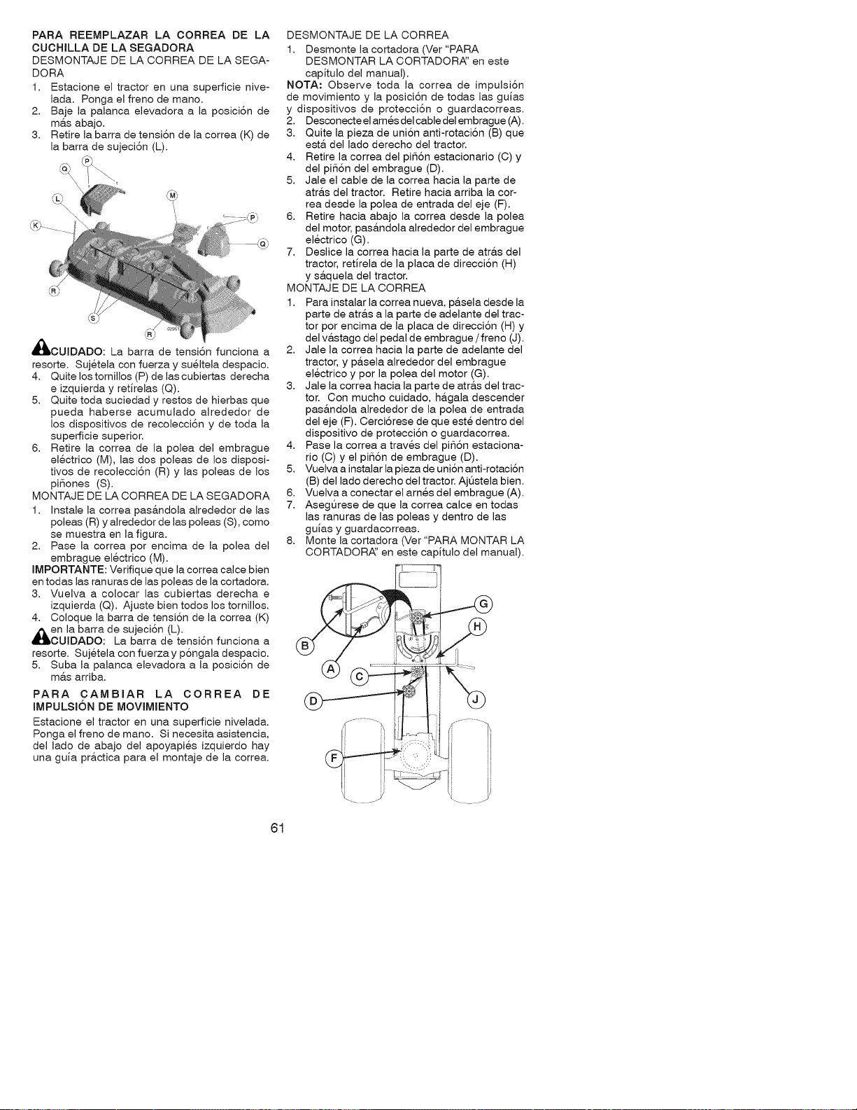
PARA REEMPLAZAR LA CORREA DE LA
CUCHILLA DE LA SEGADORA
DESMONTAJE DE LA CORREA DE LA SEGA-
DORA
1. Estacione el tractor en una superficie nive-
lada. Ponga el freno de mano.
2. Baje la palanca elevadora a la posici6n de
ma.s abajo.
3. Retire la barra de tensi6n de la correa (K) de
la barra de sujeci6n (L).
®
d_kCUIDADO: La barra de tensi6n funciona a
resorte. Sujetela con fuerza y sueltela despacio.
4. Quite los tomillos (P) de las cubiertas derecha
e izquierda y retJrelas (Q).
5. Quite toda suciedad y restos de hierbas que
pueda haberse acumulado alrededor de
los dispositivos de recolecci6n y de toda la
superficie superior.
6. Retire la correa de la polea del embrague
electrico (M), las dos poleas de los disposi-
tivos de recolecci6n (R) y las poleas de los
piSones (S).
MONTAJE DE LA CORREA DE LA SEGADORA
1. Instale la correa pas&ndola alrededor de las
poleas (R) y alrededor de las poleas (S), como
se muestra en la figura.
2. Pase la correa por encima de la polea del
embrague electrico (M).
IMPORTANTE: Verifique que la correa calce bien
en todas las ranuras de las poleas de la cortadora.
3. Vuelva a colocar las cubiertas derecha e
izquierda (Q). Ajuste bien todos los tornillos.
4. Coloque la barra de tensi6n de la correa (K)
en la barra de sujeci6n (L).
OUJDADO: La barra de tensi6n funciona a
resorte. Sujetela con fuerza y p6ngala despacio.
5. Suba la palanca elevadora a la posici6n de
m&s arriba.
PARA CAMBIAR LA CORREA DE
IMPULSI6N DE MOVlMIENTO
Estacione el tractor en una superficie nivelada.
Ponga el freno de mano. Si necesita asistencia,
del lado de abajo del apoyapies izquierdo hay
una guJa pr&ctica para el montaje de la correa.
DESMONTAJE DE LA CORREA
1. Desmonte la cortadora (Ver "PARA
DESMONTAR LA CORTADORA:' en este
capitulo del manual).
NOTA: Observe toda la correa de impulsi6n
de movimiento y la posici6n de todas las guias
y dispositivos de protecci6n o guardacorreas.
2. Desconecte el arnes delcable del embrague (A).
3. Quite la pieza de uni6n anti-rotaci6n (B) que
est& del lado derecho del tractor.
4. Retire la correa del pi56n estacionario (C) y
del pi56n del embrague (D).
5. Jale el cable de la correa hacia la parte de
atras del tractor. Retire hacia arriba la cor-
rea desde la polea de entrada del eje (F).
6. Retire hacia abajo la correa desde la polea
del motor, pasandola alrededor del embrague
electrico (G).
7. Deslice la correa hacia la parte de atras del
tractor, retirela de la placa de direcci6n (H)
y saquela del tractor.
MONTAJE DE LA CORREA
1. Para instalar la correa nueva, pasela desde la
parte de atras a la parte de adelante del trac-
tor por encima de la placa de direcci6n (H) y
del vastago del pedal de embrague / freno (J).
2. Jale la correa hacia la parte de adelante del
tractor, y pasela alrededor del embrague
electrico y por la polea del motor (G).
3. Jale la correa hacia la parte de atras del trac-
tor. Con mucho cuidado, hagala descender
pasandola alrededor de la polea de entrada
del eje (F). Oerci6rese de que este dentro del
dispositivo de protecci6n o guardacorrea.
4. Pase la correa a traves del pi_6n estaciona-
rio (C) y el pi56n de embrague (D).
5. Vuelva a instalar la pieza de uni6n anti-rotaci6n
(B) del lado derecho del tractor. Ajt_stela bien.
6. Vuelva a conectar el arnes del embrague (A).
7. Asegt]rese de que la correa calce en todas
las ranuras de las poleas y dentro de las
guJas y guardacorreas.
8. Monte la cortadora (Ver"PARA MONTAR LA
CORTADOR,_' en este capJtulo del manual).
61
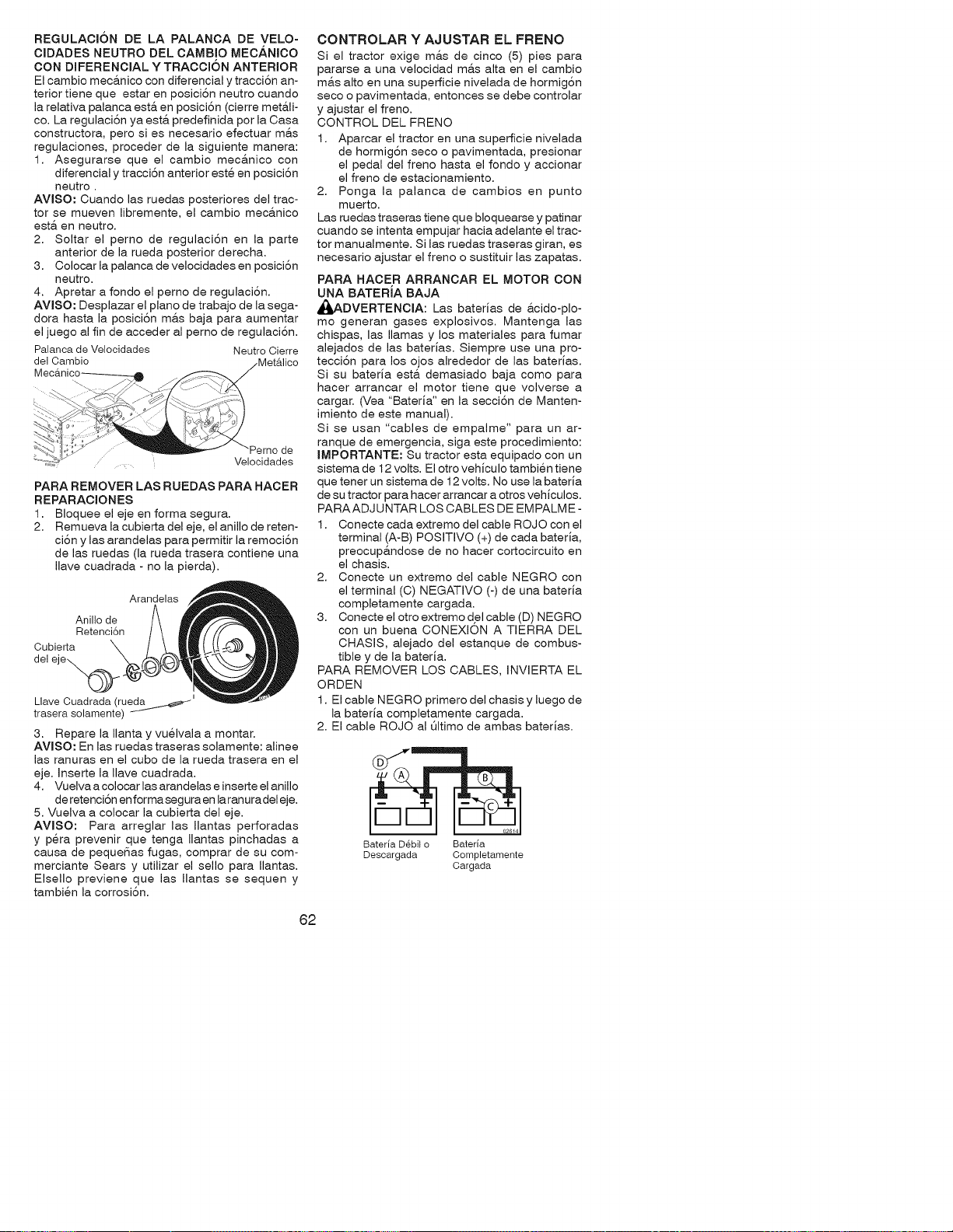
REGULACI6N DE LA PALANCA DE VELO-
CIDADES NEUTRO DEL CAMBIO MECANICO
CON DIFERENCIAL Y TRACCI6N ANTERIOR
El cambio meca.nico con diferencial y tracci6n an-
terior tiene que estar en posici6n neutro cuando
la relativa palanca est& en posici6n (cierre met&li-
co. La regulaci6n ya est& predefinida por la Casa
constructora, pero si es necesario efectuar m&s
regulaciones, proceder de la siguiente manera:
1. Asegurarse que el cambio meca.nico con
diferencial y tracci6n anterior este en posici6n
neutro .
AVISO: Cuando las ruedas posteriores del trac-
tor se mueven libremente, el cambio mec&nico
est& en neutro.
2. Soltar el perno de regulaci6n en la parte
anterior de la rueda posterior derecha.
3. Colocar la palanca de velocidades en posici6n
neutro.
4. Apretar a fondo el perno de regulaci6n.
AVlSO: Desplazar el piano de trabajo de la sega-
dora hasta la posici6n m&s baja para aumentar
el juego al fin de acceder al perno de regulaci6n.
Palanca de Velocidades Neutro Cierre
del Cambio
de
.... Velocidades
PARA REMOVER LAS RUEDAS PARA HACER
REPARACiONES
1. Bloquee el eje en forma segura.
2. Remueva la cubierta del eje, el anillo de reten-
ci6n y las arandelas para permitir la remoci6n
de las ruedas (la rueda trasera contiene una
Ilave cuadrada - no la pierda).
Arandelas
Anillo de
Retenci6n
Cubierta \
del "
Llave Cuadrada (rueda _ _
trasera solamente)
3. Repare la Ilanta y vuelvala a montar.
AVISO: En las ruedas traseras solamente: alinee
las ranuras en el cubo de la rueda trasera en el
eje. Inserte la Ilave cuadrada.
4. Vuelva a colocar las arandelas e inserte el anillo
de retenci6n en formasegura en la ranuradel eje.
5. Vuelva a colocar la cubierta del eje.
AVlSO: Para arreglar las Ilantas perforadas
y p@a prevenir que tenga Ilantas pinchadas a
causa de pequeSas fugas, comprar de su com-
merciante Sears y utilizar el sello para Ilantas.
Elsello previene que las Ilantas se sequen y
tambien la corrosi6n.
CONTROLAR Y AJUSTAR EL FRENO
Si el tractor exige m&s de cinco (5) pies para
pararse a una velocidad m&s alta en el cambio
m_,salto en una superficie nivelada de hormig6n
seco o pavimentada, entonces se debe controlar
y ajustar el freno.
CONTROL DEL FRENO
1. Aparcar el tractor en una superficie nivelada
de hormig6n seco o pavimentada, presionar
el pedal del freno hasta el fondo y accionar
el freno de estacionamiento.
2. Ponga la palanca de cambios en punto
muerto.
Las ruedas traseras tiene que bloquearse y patinar
cuando se intenta empujar hacia adelante el trac-
tor manualmente. Si las ruedas traseras giran, es
necesario ajustar el freno o sustituir las zapatas.
PARA HACER ARRANCAR EL MOTOR CON
UNA BATERJA BAJA
_ADVERTENCIA: Las baterias de &cido-plo-
mo generan gases explosivos. Mantenga las
chispas, las llamas y los materiales para fumar
alejados de las baterias. Siempre use una pro-
tecci6n para los ojos alrededor de las baterias.
Si su bateria esta. demasiado baja como para
hacer arrancar el motor tiene que volverse a
cargar. (Vea "Bateria" en la secci6n de Manten-
imiento de este manual).
Si se usan "cables de empalme" para un ar-
ranque de emergencia, siga este procedimiento:
IMPORTANTE: Su tractor esta equipado con un
sistema de 12 volts. El otro vehiculo tambien tiene
que tener un sistema de 12 volts. No use la bateria
de su tractor para hacer arrancar a otros vehiculos.
PARAADJUNTAR LOS CABLES DE EMPALME-
1. Conecte cada extremo del cable ROJO con el
terminal (A-B) POSmVO (+) de cada bateria,
preocup&ndose de no hacer cortocircuito en
el chasis.
2. Conecte un extremo del cable NEGRO con
el terminal (C) NEGATIVO (-) de una bateria
completamente cargada.
3. Conecte el otro extremo del cable (D) NEGRO
con un buena CONEXION A TIERRA DEL
CHASIS, alejado del estanque de combus-
tible y de la bateria.
PARA REMOVER LOS CABLES, INVIERTA EL
ORDEN
1. El cable NEGRO primero del chasis y luego de
la bateria completamente cargada.
2. El cable ROJO al Qltimo de ambas baterias.
Bateria D6bil o Bateria
Descargada Completamente
Cargada
62
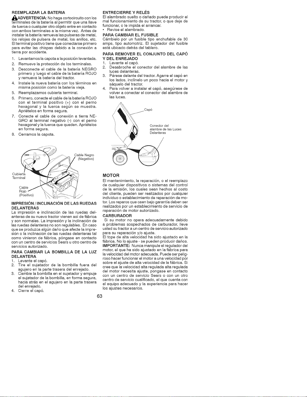
REEMPLAZAR LA BATERIA
_ADVERTENCIA: No haga cortocircuito con los
terminales de la baterJa al permitir que una Ilave
de tuerca o cualquier otro objeto entre en contacto
con ambos terminales a la misma vez. Antes de
instalar la bateria remueva las pulseras de metal,
los relojes de pulsera de metal, los anillos, etc.
Elterminal positivo tiene que conectarse primero
para evitar las chispas debido a la conexi6n a
tierra por accidente.
1. Levantamos la capota a la posici6n levantada.
2. Remueve la protecci6n de los terminales.
3. Desconecte el cable de la baterJa NEGRO
primero y luego el cable de la bateria ROJO
y remueva la bateria del tractor.
4. Instale la nueva baterJa con los t@minos en
misma posici6n como la bateria vieja.
5. Reemplazamos cubierta terminal.
6. Primero, conecte el cable de la baterJa ROJO
con el terminal positivo (+) con el perno
hexagonal y la tuerca segOn se muestra.
Aprietelos en forma segura.
7. Conecte el cable de conexi6n a tierra NE-
GRO al terminal negativo (-) con el perno
hexagonal y la tuerca que queden. Apri@elos
en forma segura.
8. Cerramos la capota.
ENTRECIERRE Y RELES
El alambrado suelto o daSado puede producir el
mal funcionamiento de su tractor, o que deje de
funcionar, o le impida el arrancar.
• Revise el alambrado.
PARA OAMBIAR EL FUSIBLE
C&mbielo por un fusible tipo enchufable de 30
amps, tipo automotriz. El sujetador del fusible
est& ubicado detr&s del tablero.
PARA REMOVER EL CONJUNTO DEL CAPO
Y DEL ENREJADO
1. Levante el cap6.
2. Desabroche el conector del alambre de las
luces delanteras.
3. P&rese delante del tractor. Agarre el cap6 en
los lades, inclJnelo un poco hacia el motor y
s&quelo del tractor.
4. Para volver a instalar el cap6, asegOrese de
volver a conectar el conector del alambre de
las luces.
Conector del
alambre de las Luces
Delanteras
_-- _. Cable Negro
Negativo)
Cubi /
Terminal
Cable J
Rojo
(Positivo) ___
IMPRESI6N / INCUNACI6N DE LAS RUEDAS
DELANTERAS
La impresi6n e inclinaci6n de las ruedas del-
anteras de su nuevo tractor vienen asJ de f&brica
y son normales. La impresi6n y la inclinaci6n de
las ruedas delanteras no son regulables. En caso
que se produzca algt_n daSo que afecte la impre-
si6n o la inclinaci6n de las ruedas delanteras tal
como vinieron de fabrica, p6ngase en contacto
con un centro de servicios Sears u otro centro de
servicios autorizado.
PARA CAMBIAR LA BOMBILLA DE LA LUZ
DELANTERA
1. Levante el cap6.
2. Tire el sujetador de la bombilla fuera del
agujero en la parte trasera del enrejado.
3. Cambie la bombilla en el sujetador y empuje
el sujetador de la bombilla, en forma segura,
hacia atra.s en el agujero en la parte trasera
del enrejado.
4. Cierre el cap6.
MOTOR
El mantenimiento, la reparaci6n, o el reemplazo
de cualquier dispositivos o sistemas del control
de la emisi6n, los cuales sean hechos al costo
del cliente, pueden ser realizados por cualquier
individuo o establecimiento de reparaci6n de mo-
tor. Los reparos que caen bajo garantJa deben ser
realizados por un establecimiento de servicio de
reparaci6n de motor autorizado.
CARBURADOR
Si su motor no opera adecuadamente debido
a problemas sospechados de carburador, Ileve
usted su tractor a un centro de servicio autorizado
para su reparaci6n y/o ajuste.
El tope de alta velocidad ha sido ajustado en la
fabrica. No Io ajuste - se pueden producir da_os.
IMPORTANTE: Nunca manipule el regulador del
motor, el que ha sido ajustado en la f&brica para
la velocidad del motor adecuada. Puede ser pelig-
roso hacer funcionar el motor a una velocidad por
sobre el ajuste de alta velocidad de la f&brica. Si
cree que la velocidad alta regulada alta regulada
del motor necesita ajuste, pongase en contacto
con un centro de servicio Sears o con un otro
centro de servicio cualificado, el que cuenta con
el equipo adecuado y la experiencia para hacer
los ajustes necesarios.
63
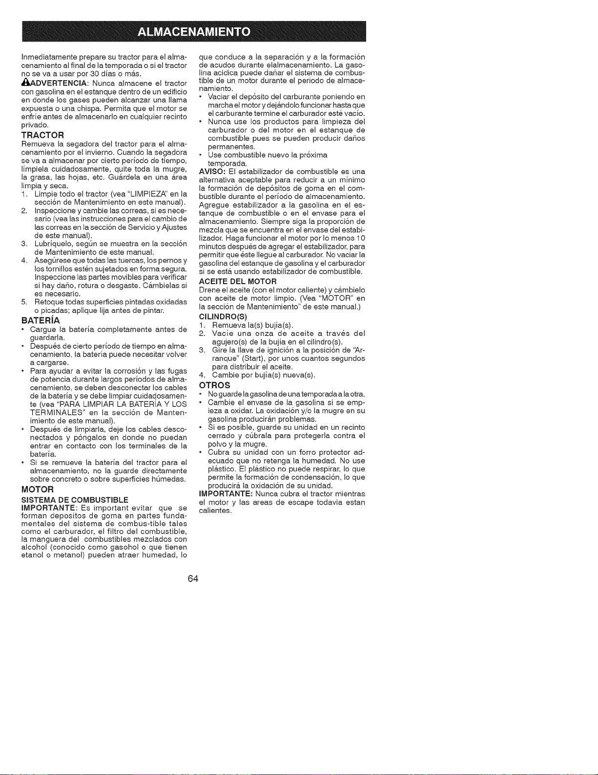
Inmediatamente prepare su tractor para el alma-
cenamiento al final de la temporada o si el tractor
no se va a usar por 30 dias o m&s.
_I_ADVERTENCIA: Nunca almacene el tractor
con gasolina en el estanque dentro de un edificio
en donde losgases pueden alcanzaruna llama
expuestaouna chispa.Permitaque elmotor se
enfrieantesde almacenarloen cualquierrecinto
privado.
TRACTOR
Remueva lasegadora deltractorpara elalma-
cenamiento por elinvierno.Cuando lasegadora
se va a almacenar por ciertoperiodode tiempo,
limpielacuidadosamente, quitetoda la mugre,
lagrasa,las hojas,etc.Gu&rdela en una &tea
limpiay seca.
I. Limpietodo eltractor(vea"LIMPIEZ,_'en la
secci6nde Mantenimientoen este manual).
2. Inspeccione y cambie las correas, si es nece-
sario (yea las instrucciones para el cambio de
las correas en la secci6n de Servicio y Ajustes
de este manual).
3. Lubriquelo, segQn se muestra en la secci6n
de Mantenimiento de este manual.
4. AsegQrese que todas las tuercas, los pemos y
los tornillos esten sujetados en forma segura.
Inspeccione las partes movibles para verificar
si hay daSo, rotura o desgaste. C&mbielas si
es necesario.
5. Retoque todas superficies pintadas oxidadas
o picadas; aplique lija antes de pintar.
BATERiA
• Cargue la bateria completamente antes de
guardarla.
• Despu@s de cierto periodo de tiempo en alma-
cenamiento, la bateria puede necesitar volver
a cargarse.
• Para ayudar a evitar la corrosi6n y las fugas
de potencia durante largos periodos de alma-
cenamiento, se deben desconectar los cables
de la bateria y se debe limpiar cuidad.osamen-
te (vea "PARA LIMPIAR LA BATERIA Y LOS
TERMINALES" en la secci6n de Manten-
imiento de este manual).
• Despues de limpiarla, deje los cables desco-
nectados y p6ngalos en donde no puedan
entrar en contacto con los terminales de la
bateria.
• Si se remueve la bateria del tractor para el
almacenamiento, no la guarde directamente
sobre concreto o sobre superficies hQmedas.
MOTOR
SISTEMA DE COMBUSTIBLE
IMPORTANTE: Es important evitar que se
forman depositos de goma en partes funda-
mentales del sistema de combus-tible tales
como el carburador, el filtro del combustible,
la manguera del combustibles mezclados con
alcohol (conocido como gasohol o que tienen
etanol o metanol) pueden atraer humedad, Io
que conduce a la separaci6n y a la formaci6n
de acudos durante elalmacenamiento. La gaso-
lina acidica puede daSar el sistema de combus-
tible de un motor durante el periodo de almace-
namiento.
• Vaciar el dep6sito del carburante poniendo en
marcha el motor y dej&ndolo funcionar hasta que
el carburante termine el carburador este vacio.
• Nunca use los productos para limpieza del
carburador o del motor en el estanque de
combustible pues se pueden producir daSos
permanentes.
• Use combustible nuevo la pr6xima
temporada.
AVlSO: El estabilizador de combustible es una
alternativa aceptable para reducir a un minimo
la formaci6n de dep6sitos de goma en el com-
bustible durante el periodo de almacenamiento.
Agregue estabilizador a la gasolina en el es-
tanque de combustible o en el envase para el
almacenamiento. Siempre siga la proporci6n de
mezcla que se encuentra en el envase del estabi-
lizador. Haga funcionar el motor por Io menos 10
minutos despues de agregar el estabilizador, para
permitir que este Ilegue al carburador. No vaciar la
gasolina del estanque de gasolina y el carburador
si se est& usando estabilizador de combustible.
AOEITE DEL MOTOR
Drene el aceite (con el motor caliente) y c&mbielo
con aceite de motor limpio. (Vea "MOTOR" en
la secci6n de Mantenimiento" de este manual.)
ClLINDRO(S)
1. Remueva la(s) bujia(s).
2. Vacie una onza de aceite a traves del
agujero(s) de la bujia en el cilindro(s).
3. Gire la Ilave de ignici6n a la posici6n de 'Ar-
ranque" (Start), por unos cuantos segundos
para distribuir el aceite.
4. Cambie por bujia(s) nueva(s).
OTROS
• No guarde lagasolina de unatemporadaa la otra.
• Cambie el envase de la gasolina si se emp-
ieza a oxidar. La oxidaci6n y/o la mugre en su
gasolina producir&n problemas.
• Si es posible, guarde su unidad en un recinto
cerrado y cQbrala para protegerla contra el
polvo y la mugre.
• Cubra su unidad con un forro protector ad-
ecuado que no retenga la humedad. No use
pl&stico. El pl&stico no puede respirar, Io que
permite la formaci6n de condensaci6n, Io que
producir& la oxidaci6n de su unidad.
IMPORTANTE: Nunca cubra el tractor mientras
el motor y las areas de escape todavia estan
calientes.
64
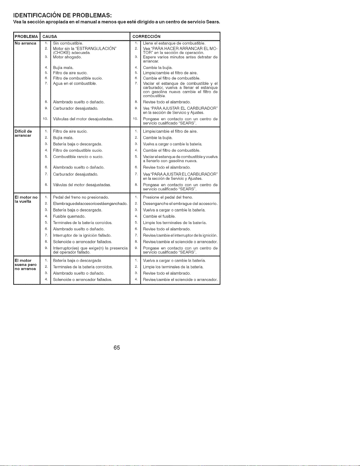
iDENTIFICACION DE PROBLEMAS:
Vea la secci6n apropiada en el manual a menos que este dirigido a un centro de servicio Sears.
PROBLEMA
NO arranca
Dificil de
arraRcar
El motor no
la vuelta
El motor
sueRa pero
Ro arranca
CAUSA
3.
4.
5.
8.
9.
10.
1.
2.
3.
4.
5.
6.
7.
1.
2.
3.
4.
5.
6.
7.
8.
9.
1.
2.
3.
4.
Sin combustible.
Motor sin la "ESTRANGULACION"
(OHOKE) adecuada.
Motor ahogado.
Bujia mala.
Filtro de aire sucio.
Filtro de combustible sucio.
Agua en el combustible.
Alambrado suelto o daSado.
Carburador desajustado.
VaJvulas del motor desajustadas.
Filtro de aire sucio.
Bujia mala.
Bateria baja o descargada.
Filtro de combustible sucio.
Combustible rancio o sucio.
Alambrado suelto o daSado.
Carburador desajustado.
Valvulas del motor desajustadas.
Pedal del freno no presionado.
Elembraguedelaccesorio est&enganchado.
Bateria baja o descargada.
Fusible quemado.
Terminales de la bateria corroidos.
Alambrado suelto o da5ado.
Interruptor de la ignici6n fallado.
Solenoide o arrancador fallados.
Interruptor(es) que exige(n) la presencia
del operador fallado.
Bateria baja o descargada
Terminales de la bateria corroidos.
Alambrado suelto o daSado.
Solenoide o arrancador fallados.
CORRECCION
1. Mene el estanque de combustible.
2. Vea"PARA HACER ARRANCAR EL MO-
TOR" en la secci6n de operaci6n.
3. Espere varios minutos antes detratar de
arrancar.
4. Oambie la bujia.
5. Limpie/cambie el filtro de aire.
6. Cambie el filtro de combustible.
7. Vaciar el estanque de combustible y el
carburador, vuelva a Ilenar el estanque
con gasolina nueva cambie el filtro de
combustible.
8. Revise todo el alambrado.
9. Vea"PARA AJUSTAR EL CARBURADOR"
en la secci6n de Servicio y Ajustes.
10. Pongase en contacto con un centro de
servicio cualificado "SEARS".
1. Limpie/cambie el filtro de aire.
2. Oambie la bujia.
3. Vuelva a cargar o cambie la bateria.
4. Cambie el filtro de combustible.
5. Vaciar el estanque de combustible y vuelva
a Ilenarlo con gasolina nueva.
6. Revise todo el alambrado.
7. Vea"PARAAJUSTAR ELCARBURADOR"
en la secci6n de Servicio y Ajustes.
8. Pongase en contacto con un centro de
servicio cualificado "SEARS".
1. Presione el pedal del freno.
2. Desengancheelembrague del accesorio.
3. Vuelva a cargar o cambie la bateria.
4. Cambie el fusible.
5. Limpie los terminales de la bateria.
6. Revise todo el alambrado.
7. Revise/cambieelinterruptordelaignici6n.
8. Revise/cambie el solenoide o arrancador.
9. Pongase en contacto con un centro de
servicio cualificado "SEARS".
1. Vuelva a cargar o cambie la bateria.
2. Limpie los terminales de la bateria.
3. Revise todo el alambrado.
4. Revise/cambie el solenoide o arrancador.
65
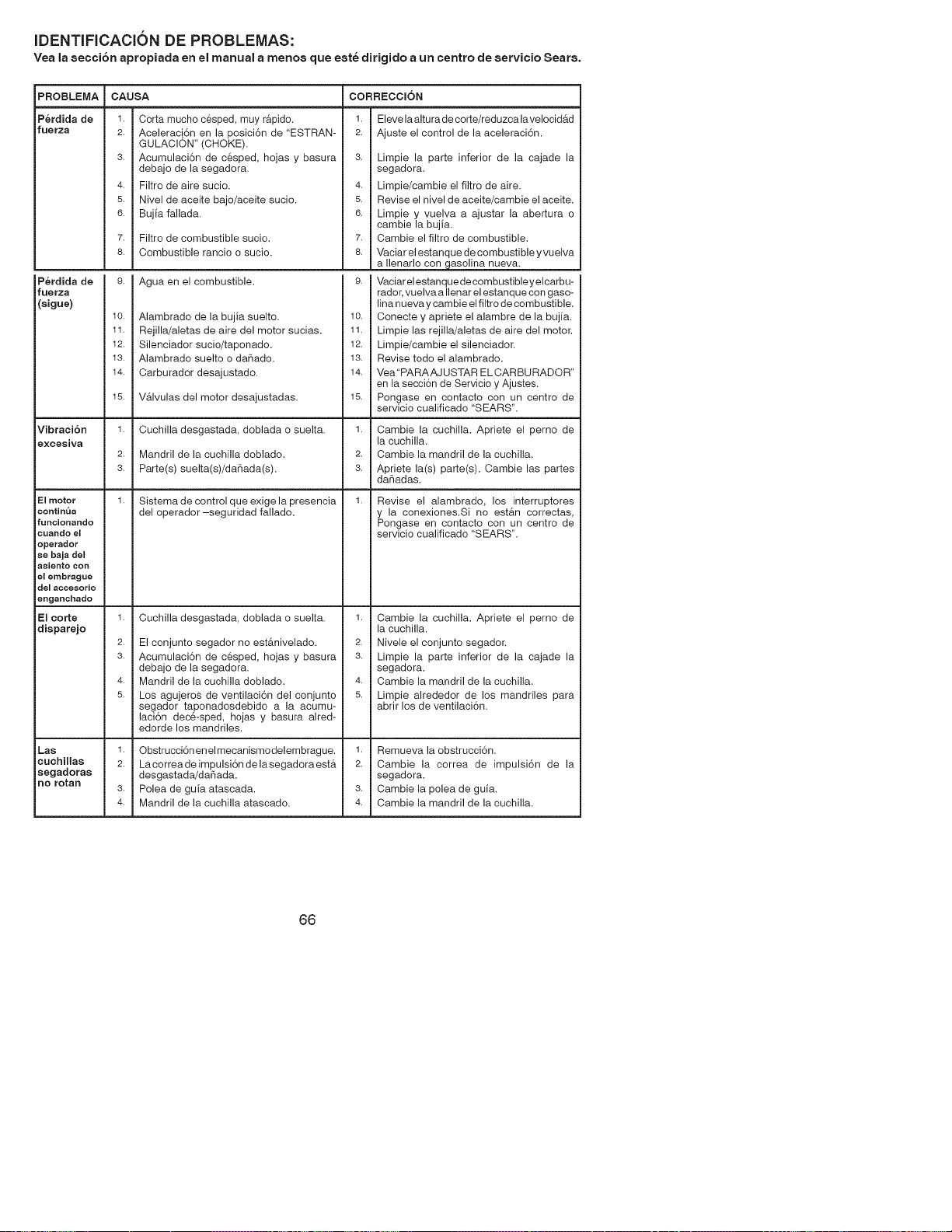
iDENTIFICACION DE PROBLEMAS:
Yea Is secci6n apropiada en el manual a menos que este dirigido a un centro de servicio Sears.
PROBLEMA
P_rdida de
fuerza
P_rdida de
fuerza
(sigue)
Vibraci6n
excesiva
El motor
contim_a
funcionando
cuando el
operador
se baja del
asiento con
el embrague
del accesorio
enganchado
El corte
disparejo
Las
cuehillas
segadoras
no rotan
CAUSA
1.
2.
3.
4.
5.
6.
Corta mucho cesped, muy r&pido.
Aceleraci6n en la posici6n de "ESTRAN-
GULACION" (CHOKE).
Acumulaci6n de cesped, hojas y basura
debajo de la segadora.
Filtro de aire sucio.
Nivel de aceite bajo/aceite sucio.
Bujia fallada.
7. Filtro de combustible sucio.
8. Combustible rancio o sucio.
1.
2.
3.
1.
Agua en el combustible.
1.
2.
3.
4.
5.
Alambrado de la bujia suelto.
Rejilla/aletas de aire del motor sucias.
Silenciador sucio/taponado.
Alambrado suelto o daSado.
Carburador desajustado.
V&lvulas del motor desajustadas.
Cuchilla desgastada, doblada o suelta.
Mandril de la cuchilla doblado.
Parte(s) suelta(s)/daSada(s).
Sistema de control que exige la presencia
del operador-seguridad fallado.
Cuchilla desgastada, doblada o suelta.
El conjunto segador no est&nivelado.
Acumulaci6n de cesped, hojas y basura
debajo de la segadora.
Mandril de la cuchilla doblado.
Los agujeros de ventilaci6n del conjunto
segador taponadosdebido a la acumu-
laci6n deck-sped, hojas y basura alred-
edorde los mandriles.
CORRECCION
1. Eleve la altu ra de corte/reduzca la velocid_.d
2. Ajuste el control de la aceleraci6n.
4.
5.
6.
1.
2.
3.
1.
1.
2.
3.
4.
5.
Obstrucci6n enel mecanismodelembrague. 1.
La correade impulsi6n de lasegadora est& 2.
desgastada/daSada.
Polea de guia atascada. 3.
Mandril de la cuchilla atascado. 4.
Limpie la parte inferior de la cajade la
segadora.
Limpie/cambie el filtro de aire.
Revise el nivel de aceite/cambie el aceite.
Limpie y vuelva a ajustar la abertura o
cambie la bujia.
Cambie el filtro de combustible.
Vaciar el estanque de combustible y vuelva
a Ilenarlo con gasolina nueva.
Vaciar el estanquedecombustibleyelcarbu-
rador, vuelva a Ilenar el estanque con gaso-
lina nueva y cambie el filtro de combustible.
Conecte y apriete el alambre de la bujia.
Limpie las rejilla/aletas de aire del motor.
Limpie/cambie el silenciador.
Revise todo el alambrado.
Vea"PARAAJ USTAR EL CARBURADOR"
en la secci6n de Servicio y Ajustes.
Pongase en contacto con un centro de
servicio cualificado "SEARS".
Cambie la cuchilla. Apriete el perno de
la cuchilla.
Cambie la mandril de la cuchilla.
Apriete la(s) parte(s). Cambie las partes
daSadas.
Revise el alambrado, los interruptores
y la conexiones.Si no est&n correctas,
Pongase en contacto con un centro de
servicio cualificado "SEARS".
Cambie la cuchilla. Apriete el perno de
la cuchilla.
Nivele el conjunto segador.
Limpie la parte inferior de la cajade la
segadora.
Cambie la mandril de la cuchilla.
Limpie alrededor de los mandriles para
abrir los de ventilaci6n.
Remueva la obstrucci6n.
Cambie la correa de impulsi6n de la
segadora.
Cambie la polea de guia.
Cambie la mandril de la cuchilla.
66
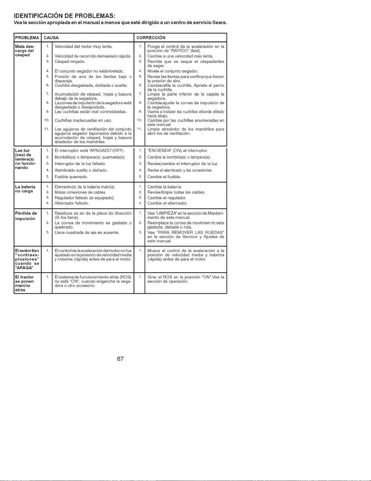
iDENTIFICACION DE PROBLEMAS:
Yea la secci6n apropiada en el manual a menos que este dirigido a un centro de servicio Seats.
PROBLEMA
Mala des=
carga dei
c_sped
Las luz
(ces) de
lantera(s)
no funcio-
nando
La bateria
nO carga
P_rdida de
impulei6n
El motor tien
"contraex=
)moaiones"
CLlando se
"APAGA"
El tractor
ee poReR
marcha
atr_s
CAUSA
1.
2.
3.
4.
5.
6.
7.
8.
9.
10.
11.
Velocidad del motor muy lenta.
Velocidad de recorrido demasiado r&pida.
Cesped mojado.
El conjunto segador no est&nivelado.
Presi6n de aire de las Ilantas baja o
dispareja.
Cuchilla desgastada, doblada o suelta.
Acumulaci6n de c6sped, hojas y basura
debajo de la segadora.
Lacorrea de impulsi6n de la segadora est&
desgastada o desajustada.
Las cuchillas est&n mal coninstaladas.
Cuchillas inadecuadas en uso.
Los agujeros de ventilaci6n del conjunto
agujeros segador taponados debido a la
acumulaci6n de c6sped, hojas y basura
alrededor de los mandriles.
CORRECCION
1. Ponga el control de la aceleraci6n en la
posici6n de "RAPIDO" (fast).
2. Cambie a una velocidad m&s lenta.
3. Permita que se seque el c_spedantes
de segar.
4. Nivele el conjunto segador.
5. Revise las Ilantas paraverificarquetienen
la presi6n de aire.
6. Cambie/afile la cuchilla. Apriete el perno
de la cuchilla.
7. Limpie la parte inferior de la cajade la
segadora.
8. Cambie/ajuste la correa de impulsi6n de
la segadora.
9. Vuelva a instalar las cuchiltas elborde afilado
hacia abajo.
10. Cambie por las cuchillas enumeradas en
este manual.
11. Limpie alrededor de los mandriles para
abrir los de ventilaci6n.
El interruptor est,. '_,PAGADO"(OFF).
Bombilla(s) o I&mpara(s) quemada(s).
Interruptor de la luz fallado.
Alambrado suelto o daSado.
Fusible quemado.
"ENCIEND,_' (ON) el interruptor.
Cambie la bombilla(s) o I&mpara(s).
Revise/cambie el interruptor de la luz.
Revise el alambrado y las conexiones.
Cambie el fusible.
1. Elemento(s) de la bateria malo(s).
2. Malas conexiones de cables.
3. Regulador fallado (si equipado).
4. Alternador fallado.
1. Cambie la bateria.
2. Revise/limpie todas las cables.
3. Cambie el regulador.
4. Cambie el alternador.
1. Residuos es en de la placa de direcci6n
(Si los tiene).
2. La correa de movimiento es gastado o
quebrado.
3. Llave cuadrada de eje es ausente.
1. Vea"LIMPIEZ,_' en la secci6n de Manteni-
mento de este manual.
2. Reemplace la correade movimien-to esta
gastada, daSada o rota.
3. Vea "PARA REMOVER LAS RUEDAS"
en la secci6n de Servicio y Ajustes de
este manual.
1. Elcontroldelaaceleraci6ndelmotornofue 1. Mueva el control de la aceleraci6n a la
ajustado en la posici6n develocidad media posici6n de velocidad media y m&xima
y m&xima (r&pida) antes de para el motor. (r&pida) antes de para el motor.
1. El sistemade funcionamiento atr&s (ROS) 1. Girar el ROS en la posici6n "ON".Vea la
no est& "ON", cuando enganche la sega- secci6n de operaci6n.
dora o otro accesorio.
67

68

69

70
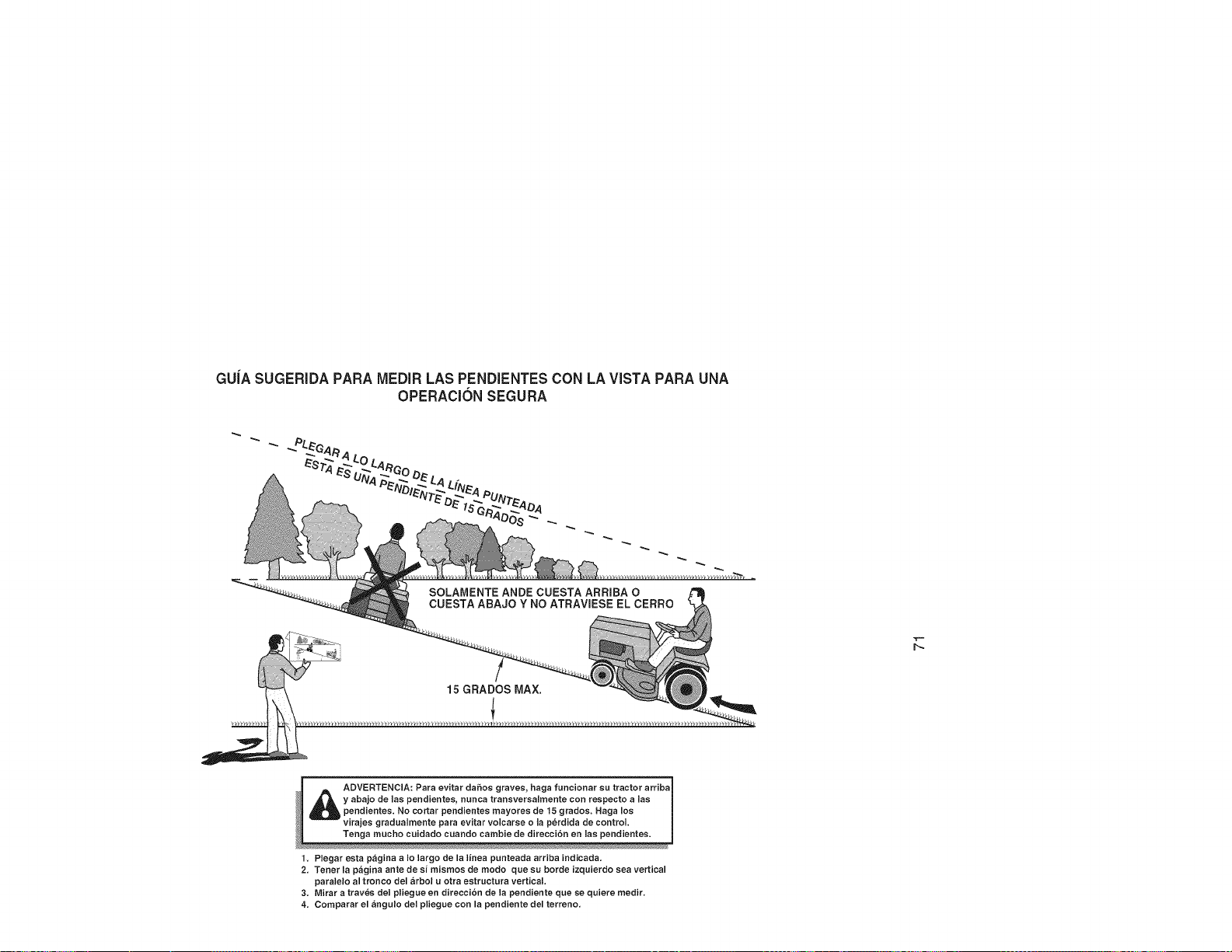
GU[A SUGERIDA PARA MEDIR LAS PENDIENTES CON LA VISTA PARA UNA
OPERACl6N SEGURA
SOLAMENTE ANDE CUESTA ARRIBA O
CUESTA ABAJO Y NO ATRAVIESE EL CERRO
15 GRADOS MAX.
_ DVERTENClA: Para evitar dafios graves, haga funcionar su tractor arriba
y abajo de las pendientes, nunca tranaversalmente con respecto alas
pendientes. No cortar pendientes mayores de 15 grados. Haga los
virajes gradualmente para evitar volcarse o la perdida de control.
Tenga mucho cuidado cuando cambie de direcciSn en las pendientea.
1. Plegar esta pagina a Io largo de la linea punteada arriba indicada.
2. Tener la pagina ante de si mismos de modo que su borde izquierdo sea vertical
paralelo al tronco del arbol u otra estructura vertical.
3. Mirar a traves del pliegue en direccibn de la pendiente que se quiere medir.
4. Comparar el angulo del pliegue con la pendiente del terreno.

: . Findthis andat[ your other product manuatsonline.
: Getanswersfrom our team of homeexperts.
: " Geta personalizedmaintenanceplan for your home.
: . Findinformation andtools to help with homeprojects.
manage _ home
b_o_sgh_ to yo_sb2 Sea_s
[$ i $ $ ] i [ )}
Your Home
For repair - in your home - of all major brand appliances,
lawn and garden equipment, or heating and cooling systems,
no matter who made it, no matter who sold it!
For the replacement parts, accessories and
owner's manuals that you need to do-it-yourself.
For Sears professional installation of home appliances
and items like garage door openers and water heaters.
1-800-4-MY-HOIVlE ® Anytime,dayor night
(1-800-469-4663) (U.S.A.andCanada)
www.sears.com www.sears.ca
Our Home
For repair of carry-in products like vacuums, lawn equipment,
and electronics, call or go on-line for the nearest
Sears Parts and Repair Center.
1-800-488-1222 Anytime,day or night (U.S.A.only)
www.sears.com
To purchase a protection agreement (U.S.A.)
or maintenance agreement (Canada) on a product serviced by Sears:
1-800-827-6655 (U.S.A.) 1-800-361-6665 (Canada)
11.01.12 JM
Para pedir servicio de reparaci6n
a domicilio, y para ordenar piezas:
1-888-.SU-HOGAR _
(1488-7844427)
Au Canada pour service en frangais:
1-800-LE-FOYER Mc
(1-800-533-6937)
www.sears.oa
@Sears Brands, LLC
® Registered Trademark / TMTrademark / sMService Mark of Sears Brands, LLC
® Marca Registrada / TMMarca de Fabrica / SM Marca de Servicio de Sears Brands, LLC
_c Marque de commerce / MDMarque deposee de Sears Brands, LLC
Printed in the U.S.A.