
Operator's Manual
(RRFTSMRN°
26.0 HR
Electric
T
Mower
Automatic Transmission
Model No.
917.28746
• Espahot, p. 35
This product has a low emission engine which operates
[]_j] differentmy from previousmy built engines. Before start the
you
engine, read and understand this Owner's Manual
Read and follow all Safety
Rules and instructions before
operating this equipment.
For answers to your questions
about this product, Call:
1-800-659-5917
Sears Craftsman Hemp Line
5 am =5 pm, Men = Sat
SEARS, ROEBUCK AND CO., HOFFMAN ESTATES, IL 60179 U.S.A.
Visit our Craftsman website:www.sears.com/craftsman

Warranty ................................................ 2
Safety Rules .......................................... 3
Product Specifications ........................... 6
Assembly/Pre=Operation ....................... 8
Operation ............................................. 12
Maintenance Schedule ........................ 20
Maintenance ........................................ 20
Service and Adjustments ..................... 24
Storage ................................................ 31
Troubleshooting ................................... 32
Sears Service ........................ Back Cover
LIMITED WARRANTY ON CRAFTSMAN TRACTOR AND BATTERY
2_YEAR ON TRACTOR
VVhen used and maintained according to the operator's manual instructions, if this tractor
fails due to a defect in material or workmanship within two years from the date of pur-
chase, call 1-800-4-MY-HOME® to arrange for free repair.
During the first 30 days of purchase, there will be no charge to service the product in
your home. For your convenience, in-home warranty service will still be available after
the first 30 days of purchase, but a trip charge will apply. This charge will be waived if
you transport the product to an authorized Craftsman drop-off location. For the nearest
authorized location, catt 1-800-4-MY=HOME®.
Tractor warranty coverage does not include:
Expendable items which become worn during normal use, including but not limited to
blades, spark plugs, air cleaners, belts, and oil filters.
Standard maintenance servicing, oil changes, or tune-ups.
Tire replacement or repair caused by punctures from outside objects, such as nails,
thorns, stumps, or glass.
Repairs necessary because of operator abuse, including but not limited to damage
caused by towing objects beyond the capability of the tractor, impacting objects that
bend the frame or crankshaft, or over-speeding the engine.
Repairs necessary because of operator negligence, including but not limited to electri-
cal and mechanical damage caused by improper storage, failure to use the proper
grade and amount of engine oil, faiture to keep the deck clear of flammaMe debris,
or failure to maintain the equipment according to the instructions contained in the
operator's manual
Engine (fuel system) cleaning or repairs necessary because of fuel determined to be
contaminated or oxidized (stale). In general fuel should be used within 30 days of its
purchase date.
Normal deterioration and wear of the exterior finishes, or product label replacement.
The tractor battery, which is covered for only 90 days as stated below.
90-DAYS ON BATTERY
For ninety (90) days from the date of purchase, if the battery included with this tractor is
defective in material or workmanship (our testing proves it will not hold a charge), it will
be replaced free of charge.
During the first 30 days of purchase, there will be no charges to replace the battery in
your home. For your convenience, in-home warranty service wilt still be available after
the first 30 days of purchase, but a trip charge will apply. This charge will be waived if
you transport the battery to an authorized Craftsman drop-off location. For the nearest
authorized location, call 1-800-4-MY=HOME®.
AH tractor and battery warranty coverage is void if this product is used for commercial or
rental purposes.
This warranty appUies only while this product is within the United States.
This warranty gives you specific legal rights, and you may atso have other rights, which
vary, from state to state.
Sears, Roebuck and Co., Hoffman Estates, IL 60179
2
_DANGER: This cutting machine is capable of amputating hands and feet and
throwing objects. Failure to observe the following safety instructions could result
in serious injury or death.
_WARNING: In order to prevent ac=
cidentat starting when setting up, trans-
porting, adjusting or making repairs,
always disconnect spark plug wire and
place wire where it cannot contact spark
plug.
_I_WARNING: Do not coast down a hitl in
neutral, you may lose control of the tractor.
,_WARNJNG: Tow only the attachments
that are recommended by and comply with
specifications of the manufacturer of your
tractor. Use common sense when towing.
Operate only at the lowest possible speed
when on a slope. Too heavy of a load,
while on a slope, is dangerous. Tires can
lose traction with the ground and cause
you to lose control of your tractor.
_WARNING: Engine exhaust, some of
its constituents, and certain vehicle com-
ponents contain or emit chemicals known
to the State of California to cause cancer
and birth defects or other reproductive
harm.
_WARNING: Battery posts, terminals
and related accessories contain lead and
lead compounds, chemicals known to the
State of California to cause cancer and
birth defects or other reproductive harm.
Wash hands after handling.
L GENERAL OPERATION
, Read, understand, and follow ati instruc-
tions on the machine and in the manual
before starting.
Do not put hands or feet near rotating
parts or under the machine. Keep clear
of the discharge opening at all times.
Only allow responsible adults, who are
familiar with the instructions, to operate
the machine.
Clear the area of objects such as rocks,
toys, wire, etc., which could be picked
up and thrown by the blades.
Be sure the area is clear of bystand-
ers before operating. Stop machine if
anyone enters the area.
Never carry passengers.
Do not mow in reverse unless abso-
lutely necessary. Always look down and
behind before and while backing.
Never direct discharged material toward
anyone. Avoid discharging material
against a wall or obstruction. Material
may ricochet back toward the operator.
Stop the blades when crossing gravel
surfaces.
Do not operate machine without the
entire grass catcher, discharge guard, or
other safety devices in place and work-
ing.
Slow down before turning.
Never leave a running machine unat-
tended. Always turn off blades, set
parking brake, stop engine, and remove
keys before dismounting.
Disengage blades when not mowing.
Shut off engine and wait for all parts to
come to a complete stop before clean-
ing the machine, removing the grass
catcher, or unclogging the discharge
guard.
Operate machine only in daylight or
good artificial light.
Do not operate the machine while under
the influence of alcohol or drugs.
Watch for traffic when operating near or
crossing roadways.
Use extra care when loading or unload-
ing the machine into a trailer or truck.
A_ways wear eye protection when oper-
ating machine.
Data indicates that operators, age 60
years and above, are involved in a large
percentage of riding mower-related in=
juries. These operators should evaluate
their ability to operate the riding mower
safely enough to protect themselves and
others from serious injury.
Follow the manufacturer's recommen-
dation for wheel weights or counter-
weights.
Keep machine free of grass, leaves or
other debris build=up which can touch
hot exhaust / engine parts and burn. Do
not allow the mower to plow leaves or
other debris which can cause build=up
to occur. Clean any oil or fuel spillage
before operating or storing the machine.
Allow machine to cool before
storage.
3
[L SLOPE OPERATION
Slopes are a major factor related to loss of
control and tip-over accidents, which can
result in severe injury or death. Opera-
tion on aH slopes requires extra caution. If
you cannot back up the slope or if you feel
uneasy on it, do not mow it.
Mow up and down slopes, not across.
o Watch for holes, ruts, bumps, rocks, or
other hidden objects. Uneven terrain
could overturn the machine. Tall grass
can hide obstacles.
Choose a low ground speed so that you
will not have to stop or shift while on the
slope.
Do not mow on wet grass. Tires may
lose traction.
Always keep the machine in gear when
going down slopes. Do not shift to neu-
tral and coast downhill.
Avoid starting, stopping, or turning on a
slope. If the tires lose traction, disen-
gage the blades and proceed slowly
straight down the slope.
Keep all movement on the slopes slow
and gradual. Do not make sudden
changes in speed or direction, which
could cause the machine to roll over.
Use extra care while operating machine
with grass catchers or other attach-
ments; they can affect the stability of the
machine. Do no use on steep slopes.
Do not try to stabilize the machine by
putting your foot on the ground.
Do not mow near drop-offs, ditches,
or embankments. The machine could
suddenly roll over if a wheel is over the
edge or if the edge caves in.
HL CHILDREN
Tragic accidents can occur if the operator
is not alert to the presence of children.
Children are often attracted to the machine
and the mowing activity. Never assume
that children will remain where you last
saw them.
Keep children out of the mowing area
and in the watchful care of a responsible
adult other than the operator.
Be alert and turn machine off if a child
enters the area.
Before and while backing, look behind
and down for small children.
Never carry children, even with the
blades shut off. They may fall off and
be seriously injured or interfere with
safe machine operation. Children who
have been given rides in the past may
suddenly appear in the mowing area for
another ride and be run over or backed
over by the machine.
Never allow children to operate the
machine.
Use extra care when approaching blind
corners, shrubs, trees, or other objects
that may block your view of a child.
[Vo TOWING
Tow only with a machine that has a
hitch designed for towing. Do not attach
towed equipment except at the hitch
point.
Follow the manufacturer's recommenda-
tion for weight limits for towed equip-
ment and towing on slopes.
Never allow children or others in or on
towed equipment.
On slopes, the weight of the towed
equipment may cause loss of traction
and loss of control.
Travel slowly and allow extra distance to
stop.
Vo SERVICE
SAFE HANDLING OF GASOLINE
To avoid personal injury or property
damage, use extreme care in handling
gasoline. Gasoline is extremely flammable
and the vapors are explosive.
Extinguish all cigarettes, cigars, pipes,
and other sources of ignition.
Use only approved gasoline container.
Never remove gas cap or add fuel with
the engine running. Allow engine to cool
before refueling.
Never fuel the machine indoors.
Never store the machine or fuel con-
tainer where there is an open flame,
spark, or pilot light such as on a water
heater or other appliances.
Never ill[ containers inside a vehicle or
on a truck or trailer bed with plastic liner.
Always place containers on the ground
away from your vehicle when filling.
Removegas-powered equipmentfrom
the truck or trailer and refuel it on the
ground. If this is not possible, then
refuel such equipmentwith a portable
container,rather than from a gasoline
dispenser nozzle.
Keep the nozzlein contactwith the rim
of the fuel tank or container opening at
all times until fueling is complete.Do not
use a nozzle lock-open device.
If fuel is spilled on clothing, change
clothing immediately.
Never overfillfuel tank. Replacegas cap
and tighten securely.
GENERAL SERVICE
Never operatemachine in a closedarea.
Keep all nuts and bolts tight to be sure
the equipment is in safe working condi-
tion.
Never tamper with safety devices.
Check their proper operation regularly.
Keep machinefree of grass, leaves, or
other debris build-up. Clean oil orfuel
spillage and remove any fuel-soaked
debris. Allow machine to cool before
storing.
If you strike a foreign object, stop and
inspect the machine. Repair,if neces-
sary, before restarting.
Never make any adjustmentsor repairs
with the engine running.
Check grass catcher componentsand
the dischargeguard frequently and re-
place with manufacturer's recommended
parts, when necessary.
Mower blades are sharp. Wrap the
blade or wear gloves, and use extra cau-
tion when servicing them.
Check brake operationfrequently. Adjust
and service as required.
Maintain or replace safety and instruc-
tion labels, as necessary.
Be sure the area is clear of bystand-
ers before operating. Stop machine if
anyone enters the area.
Never carry passengers.
Do not mow in reverse unlessabso-
lutely necessary.Always look down and
behind before and while backing.
Never carry children, even with the
blades shut off. They may fall off and
be seriously injured or interferewith
safe machine operation. Childrenwho
have been given rides in the past may
suddenly appear in the mowing area for
anotherride and be run over or backed
over by the machine.
Keep children out of the mowing area
and in the watchful care of a responsible
adult other than the operator.
Be alert and turn machine off if a child
enters the area.
Before and while backing, look behind
and downfor smalJchildren.
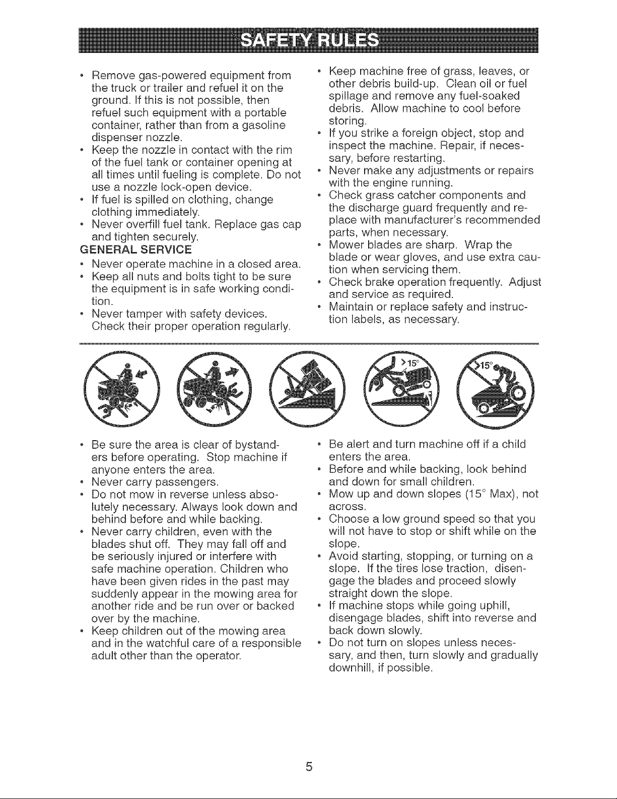
Mow up and down slopes (15° Max), not
across.
, Choose a low ground speed so that you
will not have to stop or shift while on the
slope.
, Avoid starting, stopping, or turning on a
slope. If the tires lose traction, disen-
gage the blades and proceed slowly
straight down the slope.
, if machine stops while going uphill,
disengage blades, shift into reverse and
back down slowly.
, Do not turn on slopes unless neces-
sary, and then, turn slowly and gradually
downhill, if possible.
5
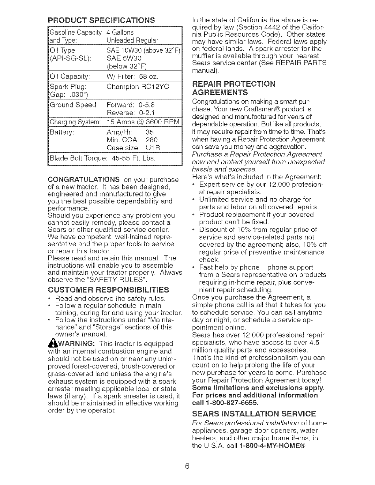
PRODUCT SPECIFmCATIONS
Gasoline Capacity 4 Gallons
and Type: Unleaded Regular
Oil Type SAE 10W30 (above 32°F
API-SG-SL): SAE 5W30
(below 32°F)
Oil Capacity: W/FHter: 58 oz.
Spark Plug: Champion RC12YC
Gap: .030")
Ground Speed Forward: 0-5.8
Reverse: 0-2.1
Charging System: 15 Amps @ 3600 RPM
Battery: Amp/Hr: 35
Min. CCA: 280
Case size: U1R
Blade Bolt Torque: 45-55 Ft. Lbs.
CONGRATULATIONS on your purchase
of a new tractor. It has been designed,
engineered and manufactured to give
you the best possible dependability and
performance.
Should you experience any problem you
cannot easily remedy, please contact a
Sears or other qualified service center.
We have competent, well-trained repre-
sentative and the proper tools to service
or repair this tractor.
Please read and retain this manual. The
instructions will enable you to assemble
and maintain your tractor properly. Always
observe the "SAFETY RULES".
CUSTOMER RESPONSIBmUTIES
, Read and observe the safety rules.
Follow a regular schedule in main-
taining, caring for and using your tractor.
Follow the instructions under "Mainte-
nance" and "Storage" sections of this
owner's manuat.
,_WARNING: This tractor is equipped
with an internal combustion engine and
should not be used on or near any unim-
proved forest-covered, brush-covered or
grass-covered land unless the engine's
exhaust system is equipped with a spark
arrester meeting applicable local or state
laws (if any). If a spark arrester is used, it
should be maintained in effective working
order by the operator.
In the state of California the above is re-
quired by law (Section 4442 of the Califor-
nia Public Resources Code). Other states
may have similar laws. Federat laws apply
on federal lands. A spark arrester for the
muffler is available through your nearest
Sears service center (See REPAIR PARTS
manual).
REPAIR PROTECTmON
Congratulations on making a smart pur-
chase. Your new Craftsman® product is
designed and manufactured for years of
dependable operation. But like aH products,
it may require repair from time to time. That's
when having a Repair Protection Agreement
can save you money and aggravation.
Purchase a Repair Protection Agreement
now and protect yourself from unexpected
hassle and expense.
Here's what's included in the Agreement:
Expert service by our 12,000 profesion-
al repair specialists.
, Unlimited service and no charge for
parts and labor on all covered repairs.
, Product replacement if your covered
product can't be fixed.
, Discount of 10% from regular price of
service and service-related parts not
covered by the agreement; also, 10% off
regular price of preventive maintenance
check.
, Fast help by phone - phone support
from a Sears representative on products
requiring in-home repair, plus conve-
nient repair scheduling.
Once you purchase the Agreement, a
simple phone catl is all that it takes for you
to schedule service. You can call anytime
day or night, or schedule a service ap-
pointment online.
Sears has over 12,000 professional repair
specialists, who have access to over 4.5
million quality parts and accessories.
That's the kind of professionalism you can
count on to help prolong the life of your
new purchase for years to come. Purchase
your Repair Protection Agreement today!
Some limitations and exclusions apply.
For prices and additional information
call 1-800-827-6655.
SEARS INSTALLATmON SERVICE
For Sears professional installation of home
appliances, garage door openers, water
heaters, and other major home items, in
the U.S.A. calt 1-800-4-MY-HOME®
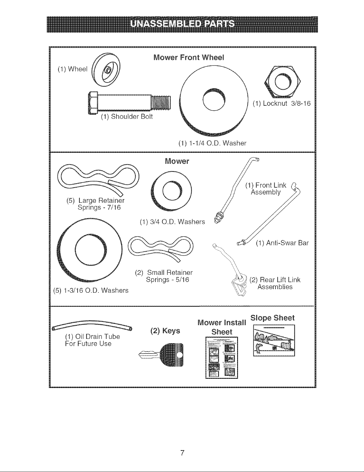
(1) Wheel
Mower Front Wheem
(1) Shoulder Bolt
(1) Locknut 3/8-16
(1) 1-1/40.D. Washer
(5) Large Retainer
Springs - 7/16
Mower
(1) 3/40.D. Washers
(l)AsFront Link
sembly
(2) Small Retainer
Springs - 5/16
(5) 1-3/16 O.D. Washers
(1) Anti-Swar Bar
(2) Rear Lift Link
Assemblies
(1) Oil Drain Tube
For Future Use
(2} Keys
Mower Install Smope Sheet
Sheet
Your new tractor has been assembled at the factory with the exception of those parts left
unassembled for shipping purposes.
TOOLS REQUmRED FOR ASSEMBLY ....
A socket wrench set will make assembly
easier. Standard wrench sizes you need
are listed below.
(1) 3/4" wrench (1) Pliers
(1) 9/16" wrench (1) Utility knife
(1) Tire pressure gauge
When right or left hand is mentioned in
this manual, it means, from your point of
view, when you are in the operating posi-
tion (seated behind the steering wheel).
TO REMOVE TRACTOR FROM
CARTON
UNPACK CARTON
1. Remove all accessible loose parts and
parts cartons from carton.
2. Cut along dashed lines on all four pan-
els of carton. Remove end panels and
lay side panels flat.
3. Remove mower and packing materials.
4. Check for any additional loose aprts or
cartons and remove.
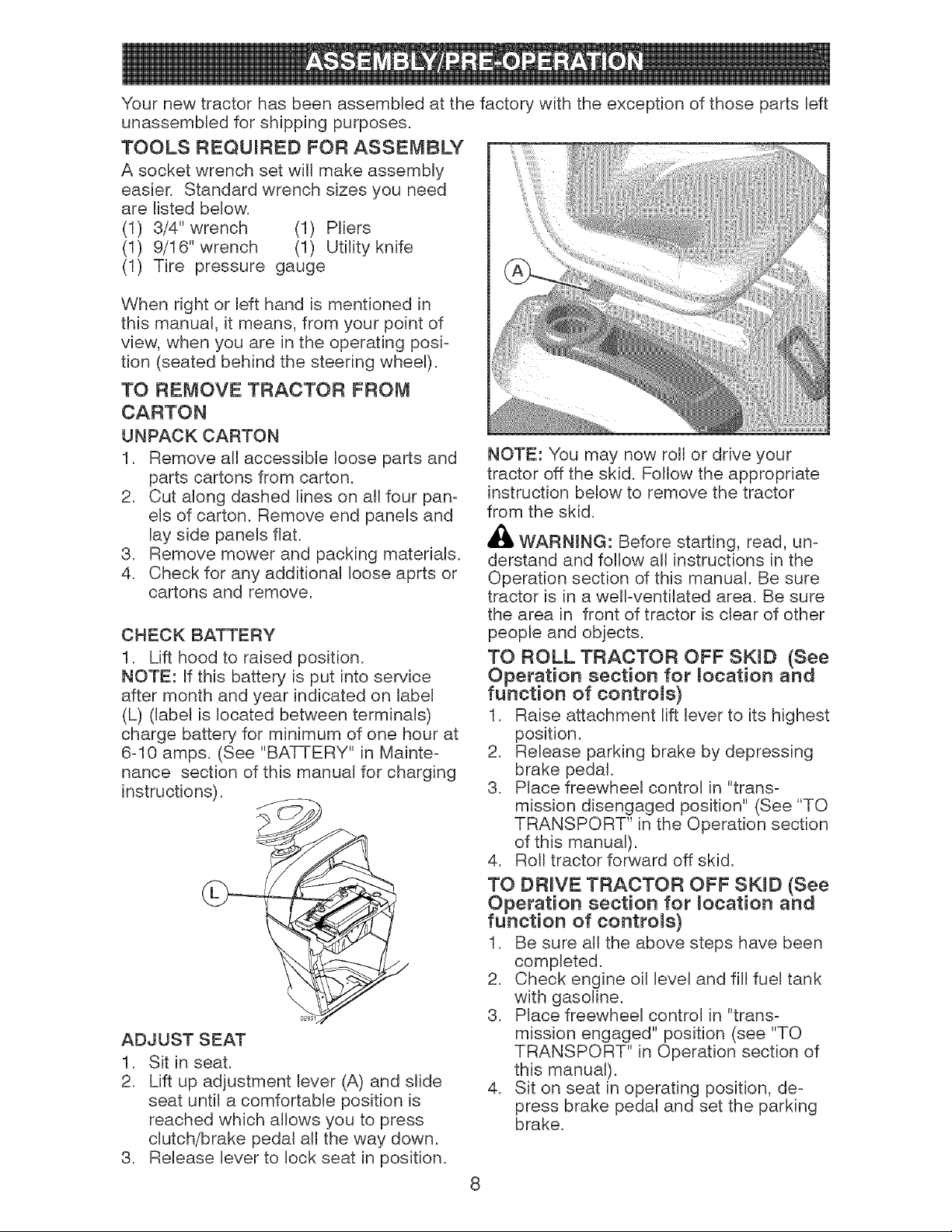
CHECK BATTERY
1. Lift hood to raised position.
NOTE: If this battery is put into service
after month and year indicated on label
(L) (label is located between terminals)
charge battery for minimum of one hour at
6-10 amps. (See "BATTERY" in Mainte-
nance section of this manual for charging
instructions).
ADJUST SEAT
1. Sit in seat.
2. Lift up adjustment lever (A) and slide
seat until a comfortable position is
reached which allows you to press
clutch/brake pedal all the way down.
3. Release lever to lock seat in position.
NOTE: You may now roll or drive your
tractor off the skid. Follow the appropriate
instruction below to remove the tractor
from the skid.
WARNING: Before starting, read, un-
derstand and follow all instructions in the
Operation section of this manual. Be sure
tractor is in a well-ventilated area. Be sure
the area in front of tractor is clear of other
people and objects.
TO ROLL TRACTOR OFF SKmD (See
Operation section for mocation and
function of controms)
1. Raise attachment lift lever to its highest
position.
2. Release parking brake by depressing
brake pedal.
3. Place freewheel control in "trans-
mission disengaged position" (See "TO
TRANSPORT" in the Operation section
of this manual).
4. Roll tractor forward off skid.
TO DRIVE TRACTOR OFF SKmD (See
Operation section for mocation and
function of controms)
1. Be sure all the above steps have been
completed.
2. Check engine oil level and fiH fuel tank
with gasoline.
3. Place freewheel control in "trans-
mission engaged" position (see "TO
TRANSPORT" in Operation section of
this manual).
4. Sit on seat in operating position, de-
press brake pedal and set the parking
brake.
5. Raiseattachment lift lever to its highest
position.
6. Removekey from bag and start the
engine (see "TO START ENGINE" in
the Operationsection of this manual).
After engine has started, move throttle
control to idle position.
7. Release parking brake.
8. Slowly depressforward drive pedal and
drive tractor off skid.
9. Apply brake to stop tractor and set
parking brake.
10.Turnignition key to "STOP" position.
Continue with the instructionsthat follow.
ASSEMBLE FRONT WHEEL TO
MOWER
1. Usingshoulder bolt, washer and
Iocknutfrom parts bag, assemble front
wheel to mower as shown. Tighten
securely.
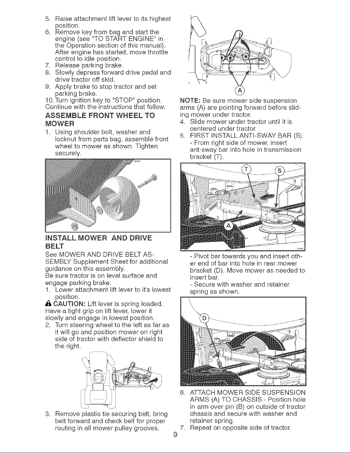
NOTE: Be sure mower side suspension
arms (A) are pointingforward before slid-
ing mower undertractor.
4. Stide mower undertractor until it is
centered undertractor.
5. FIRST INSTALLANTI-SWAYBAR (S).
- From right side of mower,insert
ant-sway bar into hole in transmission
bracket (T).
mNSTALL MOWER AND DRIVE
See MOWER AND DRIVE BELT AS-
SEMBLY Supplement Sheet for additional
guidance on this assembly.
Be sure tractor is on level surface and
engage parking brake.
1. Lower attachment lift lever to it's lowest
position.
Ai, CAUTION: Lift lever is spring loaded.
Have a tight grip on lift lever, lower it
slowly and engage in lowest position.
2. Turn steering wheel to the left as far as
it will go and position mower on right
side of tractor with deflector shield to
the right.
- Pivot bar towards you and insert oth-
er end of bar into hole in rear mower
bracket (D). Move mower as needed to
insert bar.
- Secure with washer and retainer
spring as shown.
,
Remove plastic tie securing belt, bring
belt forward and check belt for proper
routing in all mower pulley grooves.
,
,
9
ATTACH MOWER SIDE SUSPENSION
ARMS (A) TO CHASSIS - Position hole
in arm over pin (B) on outside of tractor
chassis and secure with washer and
retainer spring.
Repeat on opposite side of tractor.
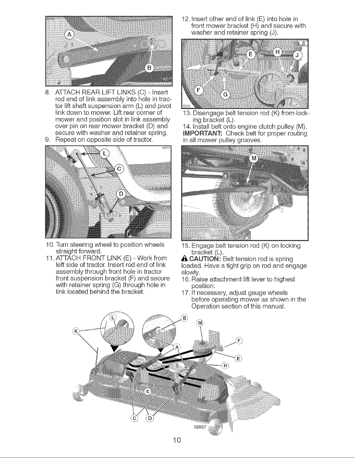
12.Insertotherend of link (E)into holein
front mowerbracket(H)andsecurewith
washerand retainerspring(J).
8. ATTACHREARLIFT LINKS(C)- Insert
rodend of linkassemblyintohole in trac-
tor liftshaft suspensionarm (L)and pivot
linkdownto mower.Liftrear cornerof
mowerand positionslotin linkassemMy
over pin on rearmowerbracket(D)and
securewith washer and retainerspring.
9. Repeaton oppositesideof tractor°
02933
13. Disengage belt tension rod (K) from lock-
ing bracket (L).
14. Install belt onto engine clutch pulley (M).
mMPORTANT: Check belt for proper routing
in all mower pulley grooves.
10. Turn steering wheel to position wheels
straight forward.
11. ATTACH FRONT LINK (E) - VVork from
left side of tractor. Insert rod end of link
assembly through front hole in tractor
front suspension bracket (F) and secure
with retainer spring (G) through hole in
link located behind the bracket.
15. Engage belt tension rod (K) on locking
bracket (L).
CAUTION: Belt tension rod is spring
loaded. Have a tight grip on rod and engage
slowly.
16. Raise attachment lift lever to highest
position.
17. If necessary, adjust gauge wheels
before operating mower as shown in the
Operation section of this manual.
02937
10
CHECK TIRE PRESSURE
The tires on your tractor were overinfiated
at the factory for shipping purposes. Cor-
rect tire pressure is important for best
cutting performance.
Reduce tire pressure to PSi shown on
tires.
CHECK DECK LEVELNESS
For best cutting results, mower hous-
ing should be properly leveled. See "TO
LEVEL MOWER" in the Service and
Adjustments section of this manual.
CHECK FOR PROPER POSITmON
OF ALL BELTS
See the figures that are shown for replac-
ing motion and mower blade drive berets
in the Service and Adjustments section
of this manual. Verify that the belts are
routed correctly.
CHECK BRAKE SYSTEM
After you learn how to operate your trac-
tor, check to see that the brake is operat-
ing properly. See "TO CHECK BRAKE"
in the Service and Adjustments section of
this manual.
Before you operate your new tractor, we
wish to assure that you receive the best
performance and satisfaction from this
Quality Product.
Please review the following checklist:
,/All assembly instructions have been
completed.
V' No remaining loose parts in carton.
V' Battery is properly prepared and
charged.
,/Seat is adjusted comfortably and tight-
ened securely.
V' All tires are properly inflated. (For ship-
ping purposes, the tires were overin-
flated at the factory).
,/Be sure mower deck is properly leveled
side-to-side/front-to-rear for best cutting
results. (Tires must be properly inflated
for leveling).
,/Check mower and drive belts. Be sure
they are routed properly around pulleys
and inside all belt keepers.
,/Check wiring. See that all connections
are still secure and wires are properly
clamped.
V' Before driving tractor, be sure freewheel
control is in "transmission engaged"
position (see "TO TRANSPORT" in the
Operation section of this manual).
While learning how to use your tractor,
pay extra attention to the following impor-
tant items:
V' Engine oil is at proper level.
V' Fuel tank is filled with fresh, clean,
regular unleaded gasoline.
,/Become familiar with all controls, their
location and function. Operate them
before you start the engine.
,/Be sure brake system is in safe operat-
ing condition.
V' Be sure Operator Presence System
and Reverse Operation System (ROS)
are working properly (See the Opera-
tion and Maintenance sections in this
manual).
,/It is important to purge the transmission
before operating your tractor for the first
time. Follow proper starting and transmis-
sion purging instructions (See "TO START
ENGINE" and "PURGE TRANSMISSION"
in the Operation section of this manual).
11
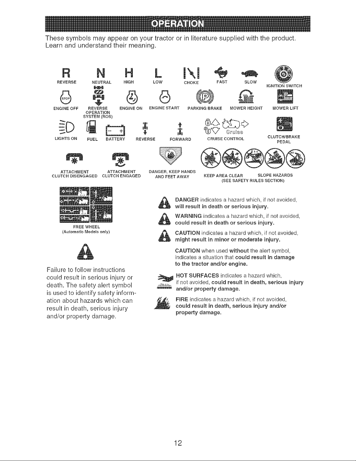
These symbols may appear on your tractor or in literature supplied with the product.
Learn and understand their meaning.
R N L IXl
REVERSE NEUTRAL H_GH LOW CHOKE FAST SLOW
ENGINE OFF REVERSE ENGINE ON ENGINE START PARKING BRAKE MOWER HEIGHT
OPERATION
SYSTEM (ROS) @__O
CRUISE CONTROL
_GNmON SW_TCH
MOWER LiFT
CLUTCH/BRAKE
LIGHTS ON FUEL BATTERY REVERSE FORWARD PEDAL
ATTACHMENT ATTACHMENT
CLUTCH D_SENGAGED CLUTCH ENGAGED
DANGER, KEEP HANDS
AND FEET AWAY KEEP AREA CLEAR SLOPE HAZARDS
(SEE SAFETY RULES SECTION)
FREE WHEEL
(Automatic Models only)
Failure to follow instructions
could result in senous injury or
death. The safety alert symbol
is used to identify safety inform-
ation about hazards whbh can
result in death, senous injury
and/or property damage.
DANGER indicates a hazard which, if not avoided,
will result in death or serious injury.
WARNING indicates a hazard which, if Rotavoided,
could result in death or serious injury.
CAUTION indicates a hazard which, if Rotavoided,
might result in minor or moderate injury.
CAUTION when used without the alert symbol,
indicates a situation that could result in damage
to the tractor and/or engine,
HOT SURFACES indicates a hazard which,
if not avoided, could result in death, serious injury
and/or property damage.
FIRE indicates a hazard which, if not avoided,
could result in death, serious injury and/or
property damage,
12
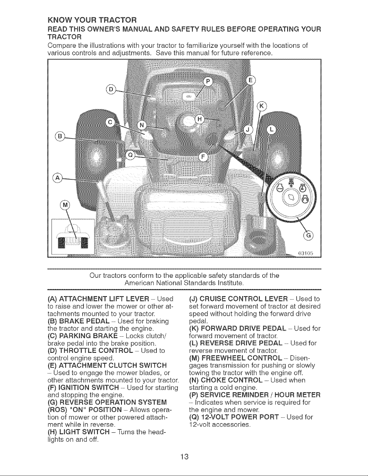
KNOW YOUR TRACTOR
READ THIS OWNER'S MANUAL AND SAFETY RULES BEFORE OPERATING YOUR
TRACTOR
Compare the itDstrations with your tractor to familiarize yourself with the locations of
various controls and adjustments. Save this manual for future reference.
08105
Our tractors conform to the applicable safety standards of the
American Nationaa Standards Institute,
(A) ATTACHMENT LIFT LEVER - Used
to raise and lower the mower or other at-
tachments mounted to your tractor.
(B) BRAKE PEDAL - Used for braking
the tractor and starting the engine.
(C) PARKING BRAKE - Locks clutch/
brake pedal into the brake position.
(D) THROTTLE CONTROL - Used to
contro_ engine speed.
(E) ATTACHMENT CLUTCH SWITCH
- Used to engage the mower blades, or
other attachments mounted to your tractor.
(F) IGNITION SWITCH - Used for starting
and stopping the engine.
(G) REVERSE OPERATION SYSTEM
(ROS) "ON" POSITION - Allows opera-
tion of mower or other powered attach-
ment white in reverse.
(H) UGHT SWITCH - Turns the head-
lights on and off.
(J) CRUISE CONTROL LEVER - Used to
set forward movement of tractor at desired
speed without holding the forward drive
pedal.
(K) FORWARD DRIVE PEDAL - Used for
forward movement of tractor.
(L} REVERSE DRWE PEDAL - Used for
reverse movement of tractor.
(M) FREEWHEEL CONTROL - Disen-
gages transmission for pushing or slowly
towing the tractor with the engine off.
(N) CHOKE CONTROL - Used when
starting a cold engine.
(P) SERVICE REMINDER / HOUR METER
- indicates when service is required for
the engine and mower.
(Q) 12oVOLT POWER PORT - Used for
12-volt accessories.
13
The operation of any tractor can result in foreign objects thrown into the
eyes, which can result in severe eye damage. Always wear safety glasses
or eye shields while operating your tractor or performing any adjustments
or repairs. We recommend standard safety glasses or a wide vision safety
mask worn over spectacles.
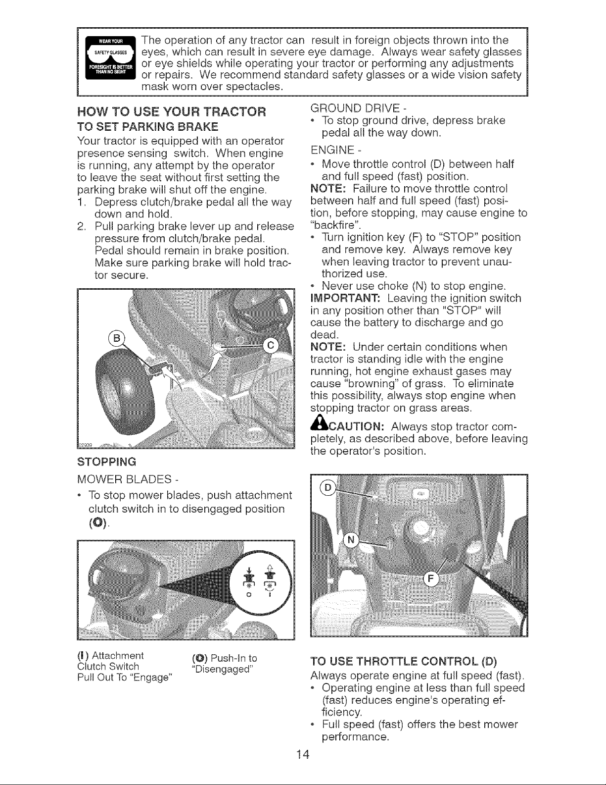
HOW TO USE YOUR TRACTOR
TO SET PARKING BRAKE
Your tractor is equipped with an operator
presence sensing switch. When engine
is running, any attempt by the operator
to leave the seat without first setting the
parking brake will shut off the engine.
1. Depress clutch/brake pedal all the way
down and hold.
2. Pull parking brake lever up and release
pressure from clutch/brake pedal.
Pedal should remain in brake position.
Make sure parking brake will hold trac-
tor secure.
GROUND DRIVE -
To stop ground drive, depress brake
pedal all the way down.
ENGINE -
* Move throttle control (D) between half
and full speed (fast) position.
NOTE: Failure to move throttle control
between half and full speed (fast) posi-
tion, before stopping, may cause engine to
"backfire".
Turn ignition key (F) to "STOP" position
and remove key. Always remove key
when leaving tractor to prevent unau-
thorized use.
Never use choke (N) to stop engine.
ff_PORTANT: Leaving the ignition switch
in any position other than "STOP" will
cause the battery to discharge and go
dead.
NOTE: Under certain conditions when
tractor is standing idle with the engine
running, hot engine exhaust gases may
cause "browning" of grass. To eliminate
this possibility, always stop engine when
stopping tractor on grass areas.
CAUTION: Always stop tractor com-
pletely, as described above, before leaving
the operator's position.
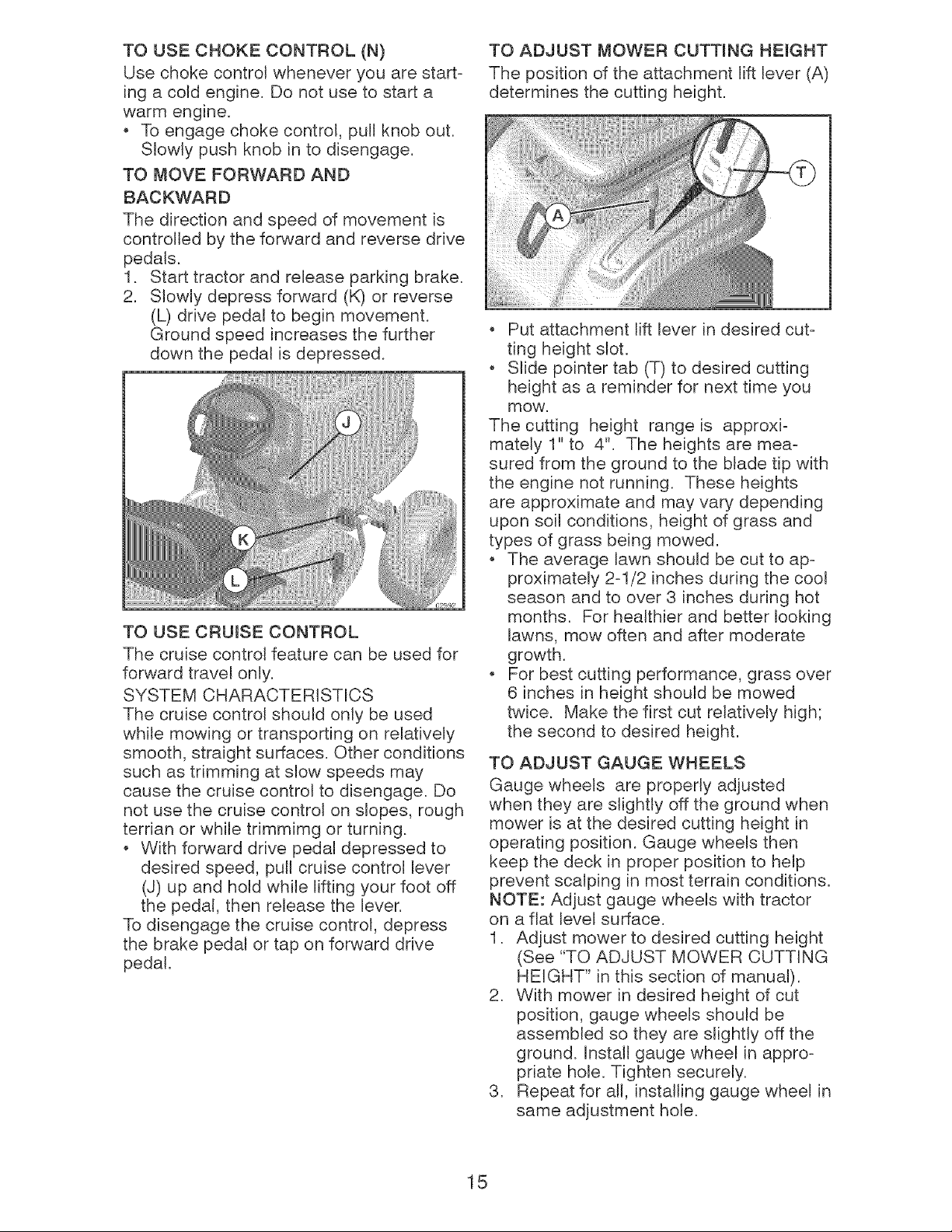
MOWER BLADES -
To stop mower blades, push attachment
clutch switch in to disengaged position
(o).
(l) Attachment
Clutch Switch
Pull Out To "Engage"
(@) Push-In to
"Disengaged"
TO USE THROTTLE CONTROL (D)
Always operate engine at full speed (fast).
Operating engine at less than full speed
(fast) reduces engine's operating ef-
ficiency.
Full speed (fast) offers the best mower
performance.
14
TO USE CHOKE CONTROL (N)
Use choke control whenever you are start-
ing a cold engine. Do not use to start a
warm engine.
To engage choke control, pull knob out.
Slowly push knob in to disengage.
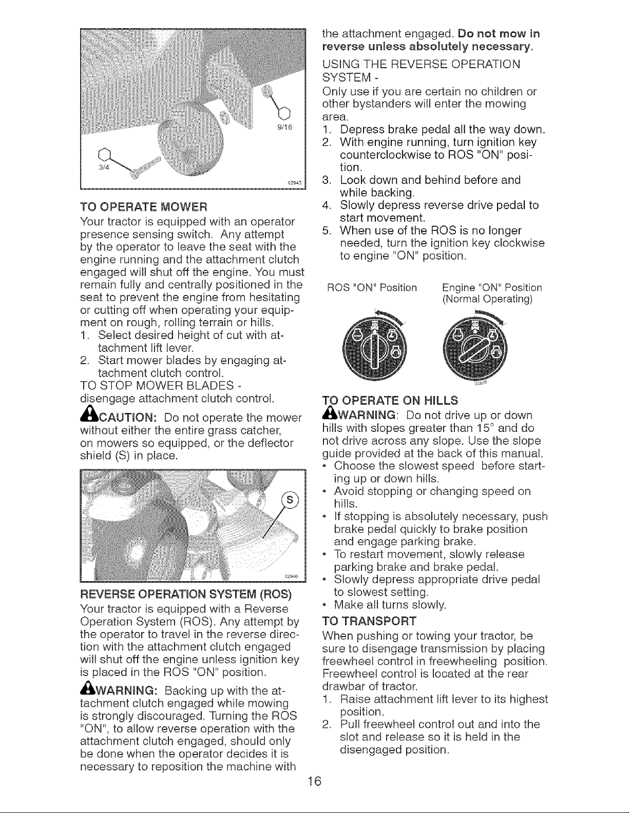
TO MOVE FORWARD AND
BACKWARD
The direction and speed of movement is
controlled by the forward and reverse drive
pedals.
1. Start tractor and release parking brake,
2. Slowly depress forward (K) or reverse
(L) drive pedal to begin movement.
Ground speed increases the further
down the pedal is depressed.
TO USE CRUISE CONTROL
The cruise control feature can be used for
forward travel only.
SYSTEM CHARACTERISTICS
The cruise control should only be used
while mowing or transporting on relatively
smooth, straight surfaces. Other conditions
such as trimming at slow speeds may
cause the cruise control to disengage. Do
not use the cruise control on slopes, rough
terrian or while trimmimg or turning.
o With forward drive pedal depressed to
desired speed, pull cruise control lever
(J) up and hold while lifting your foot off
the pedal, then release the lever.
To disengage the cruise control, depress
the brake pedal or tap on forward drive
pedal.
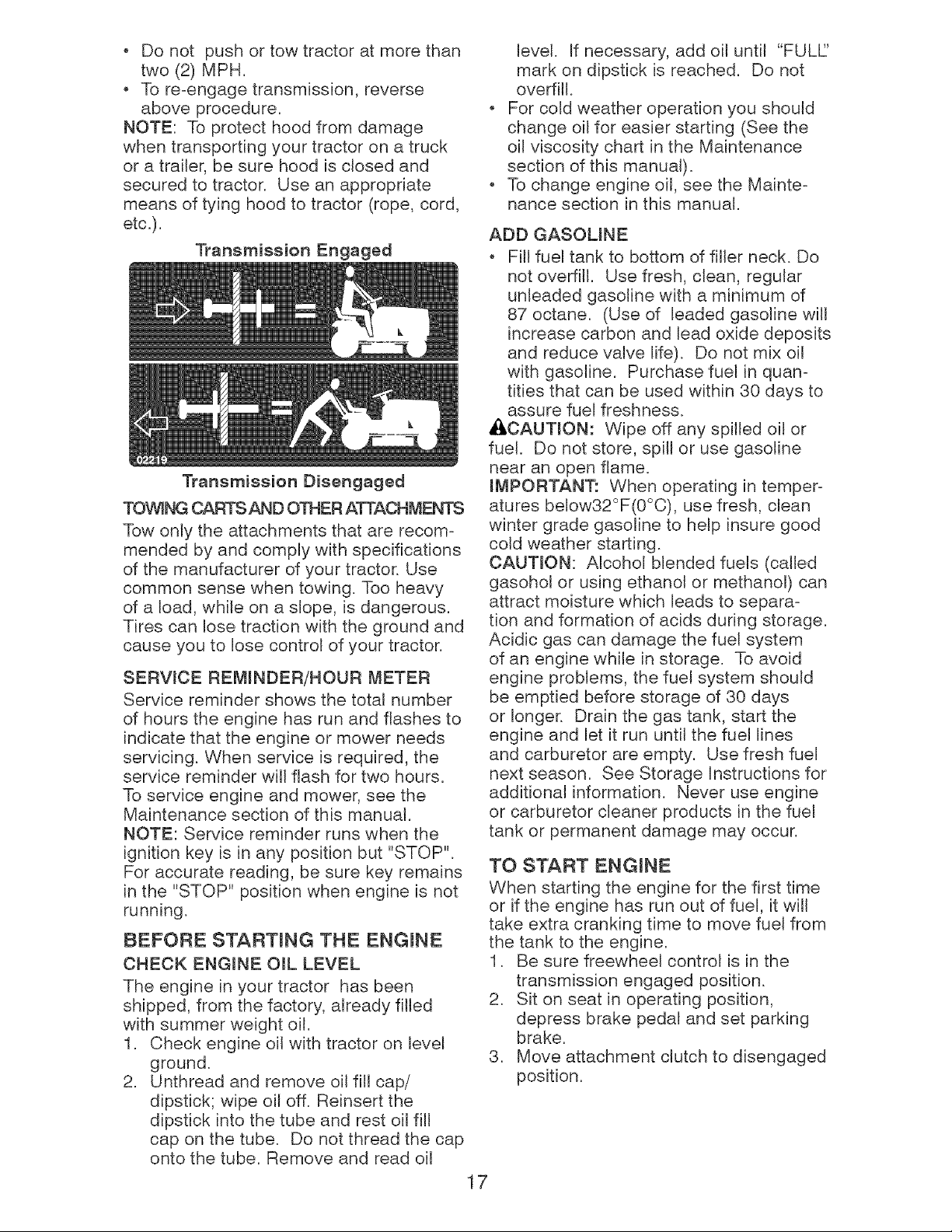
TO ADJUST MOWER CUTTING HEIGHT
The position of the attachment lift lever (A)
determines the cutting height.
Put attachment lift lever in desired cut-
ting height s_ot.
Slide pointer tab (T) to desired cutting
height as a reminder for next time you
mow.
The cutting height range is approxi-
mately 1" to 4". The heights are mea-
sured from the ground to the blade tip with
the engine not running. These heights
are approximate and may vary depending
upon soil conditions, height of grass and
types of grass being mowed.
The average lawn should be cut to ap-
proximately 2-1/2 inches during the cool
season and to over 3 inches during hot
months. For healthier and better looking
lawns, mow often and after moderate
growth.
For best cutting performance, grass over
6 inches in height should be mowed
twice. Make the first cut relatively high;
the second to desired height.
TO ADJUST GAUGE WHEELS
Gauge wheels are properly adjusted
when they are slightly off the ground when
mower is at the desired cutting height in
operating position. Gauge wheels then
keep the deck in proper position to help
prevent scalping in most terrain conditions.
NOTE: Adjust gauge wheels with tractor
on a flat level surface.
1. Adjust mower to desired cutting height
(See "TO ADJUST MOWER CUTTING
HEIGHT" in this section of manual).
2. With mower in desired height of cut
position, gauge wheels should be
assembled so they are slightly off the
ground. Install gauge wheel in appro-
priate hole. Tighten securely.
3. Repeat for all, installing gauge wheel in
same adjustment hole.
15
9/16
02943
TO OPERATE MOWER
Your tractor is equipped with an operator
presence sensing switch. Any attempt
by the operator to leave the seat with the
engine running and the attachment clutch
engaged will shut off the engine. You must
remain fully and centrally positioned in the
seat to prevent the engine from hesitating
or cutting off when operating your equip-
ment on rough, rolling terrain or hWls.
1. Select desired height of cut with at-
tachment lift lever.
2. Start mower blades by engaging at-
tachment clutch control.
TO STOP MOWER BLADES -
disengage attachment clutch control.
i_I, CAUTION: Do not operate the mower
without either the entire grass catcher,
on mowers so equipped, or the deflector
shield (S)in place.
REVERSE OPERATION SYSTEM (ROS)
Your tractor is equipped with a Reverse
Operation System (ROS). Any attempt by
the operator to travel in the reverse direc-
tion with the attachment clutch engaged
will shut off the engine unless ignition key
is placed in the ROS "ON" position.
Ai_WARNING: Backing up with the at-
tachment clutch engaged while mowing
is strongly discouraged. Turning the ROS
"ON", to allow reverse operation with the
attachment clutch engaged, should only
be done when the operator decides it is
necessary to reposition the machine with
the attachment engaged. Do not mow in
reverse unless absolutely necessary.
USING THE REVERSE OPERATION
SYSTEM -
Only use if you are certain no children or
other bystanders will enter the mowing
area.
1. Depress brake pedal all the way down.
2. With engine running, turn ignition key
counterclockwise to ROS "ON" posi-
tion.
3. Look down and behind before and
while backing.
4. Slowly depress reverse drive pedal to
start movement.
5. When use of the ROS is no longer
needed, turn the ignition key clockwise
to engine "ON" position.
ROS "ON" Position
Engine "ON" Position
(Normal Operating)
TO OPERATE ON HILLS
,_WARNJNG: Do not drive up or down
hills with slopes greater than 15 ° and do
not drive across any slope. Use the slope
guide provided at the back of this manual.
Choose the slowest speed before start-
ing up or down hiWs.
Avoid stopping or changing speed on
hills.
If stopping is absolutely necessary, push
brake pedal quickly to brake position
and engage parking brake.
To restart movement, slowly release
parking brake and brake pedal.
Slowly depress appropriate drive pedal
to slowest setting.
Make all turns slowly.
TO TRANSPORT
When pushing or towing your tractor, be
sure to disengage transmission by placing
freewheel controJ in freewheeling position.
Freewheel control is located at the rear
drawbar of tractor.
1. Raise attachment lift lever to its highest
position.
2. Pull freewheel control out and into the
slot and release so it is held in the
disengaged position.
16
Do not push or tow tractor at more than
two (2) MPH.
To re-engage transmission, reverse
above procedure.
NOTE: To protect hood from damage
when transporting your tractor on a truck
or a trailer, be sure hood is closed and
secured to tractor. Use an appropriate
means of tying hood to tractor (rope, cord,
etc.).
Transmission Engaged
Transmission Disengaged
TOWING CARTS AND OTHER ATTACHMENTS
Tow only the attachments that are recom-
mended by and comply with specifications
of the manufacturer of your tractor. Use
common sense when towing. Too heavy
of a load, while on a slope, is dangerous.
Tires can lose traction with the ground and
cause you to lose control of your tractor.
SERVICE REMINDER/HOUR METER
Service reminder shows the total number
of hours the engine has run and flashes to
indicate that the engine or mower needs
servicing. When service is required, the
service reminder will flash for two hours.
To service engine and mower, see the
Maintenance section of this manual.
NOTE: Service reminder runs when the
ignition key is in any position but "STOP".
For accurate reading, be sure key remains
in the "STOP" position when engine is not
running.
BEFORE STARTING THE ENGmNE
CHECK ENGINE OiL LEVEL
The engine in your tractor has been
shipped, from the factory, already filted
with summer weight oil.
1. Check engine oil with tractor on level
ground.
2. Unthread and remove oil fiIt cap/
dipstick; wipe oil off. Reinsert the
dipstick into the tube and rest oil fill
cap on the tube. Do not thread the cap
onto the tube. Remove and read oil
level. If necessary, add oil until "FULL'
mark on dipstick is reached. Do not
overfitl.
For cold weather operation you shoWd
change oil for easier starting (See the
oil viscosity chart in the Maintenance
section of this manual).
To change engine oil, see the Mainte-
nance section in this manual.
ADD GASOLINE
Fill fuel tank to bottom of filler neck. Do
not overfill. Use fresh, clean, regular
unleaded gasoJine with a minimum of
87 octane. (Use of leaded gasoline will
increase carbon and lead oxide deposits
and reduce valve life). Do not mix oil
with gasoline. Purchase fuel in quan-
tities that can be used within 30 days to
assure fuel freshness.
ACAUTION: Wipe off any spilled oil or
fuel. Do not store, spill or use gasoline
near an open flame.
iMPORTANT: When operating in temper-
atures below32°F(0°C), use fresh, clean
winter grade gasoline to help insure good
cold weather starting.
CAUTION: Alcohol blended fuels (called
gasohol or using ethanol or methanol) can
attract moisture which leads to separa-
tion and formation of acids during storage.
Acidic gas can damage the fuel system
of an engine while in storage. To avoid
engine problems, the fuel system should
be emptied before storage of 30 days
or longer. Drain the gas tank, start the
engine and let it run until the fuel lines
and carburetor are empty. Use fresh fuel
next season. See Storage Instructions for
additional information. Never use engine
or carburetor cleaner products in the fuel
tank or permanent damage may occur.
TO START ENGmNE
When starting the engine for the first time
or if the engine has run out of fuel, it will
take extra cranking time to move fuel from
the tank to the engine,
1. Be sure freewheel control is in the
transmission engaged position.
2. Sit on seat in operating position,
depress brake pedal and set parking
brake.
3. Move attachment clutch to disengaged
position.
17
4, Move throttle control to fast position
5, Pull choke control out for a cold engine
start attempt, For a warm engine start
attempt the choke control may not be
needed.
NOTE: Before starting, read the warm
and cold starting procedures below.
6, Insert key into ignition and turn key
clockwise to start position and release
key as soon as engine starts. Do
not run starter continuously for more
than fifteen seconds per minute. If the
engine does not start after several
attempts, push choke control in, wait
a few minutes and try again. If engine
still does not start, pull the choke con-
trol out and retry,
VVARM WEATHER STARTING (50 ° F and
above)
7, When engine starts, slowly push
choke control in until the engine
begins to run smoothly, If the engine
starts to run roughly, pull the choke
control out slightly for a few seconds
and then continue to push the control
in slowly.
The attachments and ground drive can
now be used. If the engine does not
accept the load, restart the engine and
allow it to warm up for one minute using
the choke as described above,
COLD WEATHER STARTING (50 ° F and
below)
7, When engine starts, slowly push
choke control in until the engine
begins to run smoothly. Continue to
push the choke control in small steps
allowing the engine to accept small
changes in speed and load, until the
choke control is fully in, If the engine
starts to run roughly, pull the choke
control out slightly for a few seconds
and then continue to push the control
in slowly. This may require an engine
warm-up period from several seconds
to several minutes, depending on the
temperature,
AUTOMATIC TRANSMISSION WARM UP
Before driving the unit in cold weather,
the transmission should be warmed up as
follows:
1. Be sure the tractor is on level ground.
2, Release the parking brake and let the
brake slowly return to operating posi-
tion,
3, Allow one minute for transmission to
warm up. This can be done during the
engine warm up period.
The attachments can be used during
the engine warm-up period after the
transmission has been warmed up and
may require the choke control be pulled
out slightly,
NOTE: If at a high altitude (above 3000
feet) or in cold temperatures (below 32 F)
the carburetor fuel mixture may need to
be adjusted for best engine performance
(see "TO ADJUST CARBURETOR" in the
Service and Adjustments section of this
manual),
GE TRANSMISSION
CAUTION: Never engage or dis-
engage freewheel lever while the engine
is running.
To ensure proper operation and per-
formance, it is recommended that the
transmission be purged before operating
tractor for the first time, This procedure will
remove any trapped air inside the trans-
mission which may have developed during
shipping of your tractor,
IMPORTANT: Should your transmission
require removal for service or replace-
ment, it should be purged after reinstall-
ation before operating the tractor.
1, Place tractor safely on a level surface
- that is clear of objects and open - with
engine off and parking brake set,
2, Disengage transmission by placing
freewheel control in disengaged posi-
tion (See "TO TRANSPORT" in this
section of manual).
3, Sitting in the tractor seat, start engine,
After the engine is running, move
throttle control to slow position, Disen-
_igage parking brake.
AUTION: At any time, during step
4, there may be movement of the drive
wheels.
4, Depress forward drive pedal to full
forward position and hold for five (5)
seconds and release pedal, Depress
reverse drive pedal to full reverse posi-
tion and hold for five (5) seconds and
release pedal, Repeat this procedure
three (3) times,
5. Shutoff engine and set parking brake,
6, Engage transmission by placing free-
wheel control in engaged position (See
"TO TRANSPORT" in this section of
manual),
18
)
7, Sitting in the tractor seat, start engine,
After the engine is running, move
throttle control to half (1/2) speed,
Disengage parking brake,
8, Drive tractor forward for approximately
five feet then backwards for five feet,
Repeat this driving procedure three
times.
Your transmission is now purged and now
ready for norma_ operation,
MOWING TraPS
. Tire chains cannot be used when the
mower housing is attached to tractor.
Mower should be properly leveled for
best mowing performance. See "TO
LEVEL MOWER HOUSING" in the
Service and Adjustments section of this
manual.
The left hand side of mower should be
used for trimming.
Drive so that clippings are discharged
onto the area that has already been
cut. Have the cut area to the right of
the tractor. This will result in a more
even distribution of clippings and more
uniform cutting,
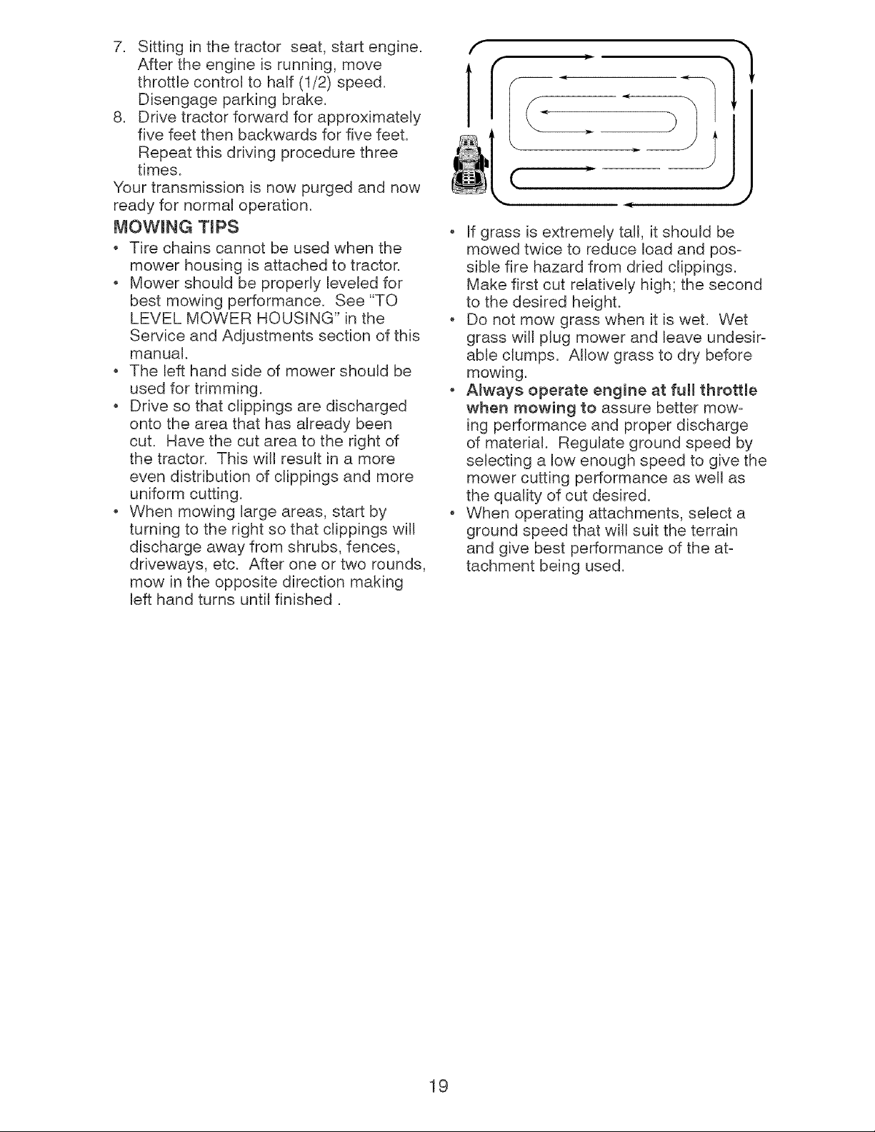
When mowing large areas, start by
turning to the right so that clippings will
discharge away from shrubs, fences,
driveways, etc. After one or two rounds,
mow in the opposite direction making
left hand turns until finished,
(
J
If grass is extremely tall, it should be
mowed twice to reduce load and pos-
sible fire hazard from dried clippings,
Make first cut relatively high; the second
to the desired height.
Do not mow grass when it is wet, Wet
grass will plug mower and leave undesir-
able clumps, Allow grass to dry before
mowing,
Always operate engine at full throttle
when mowing to assure better mow-
ing performance and proper discharge
of material. Regulate ground speed by
selecting a low enough speed to give the
mower cutting performance as well as
the quality of cut desired.
. When operating attachments, select a
ground speed that will suit the terrain
and give best performance of the at-
tachment being used.
19
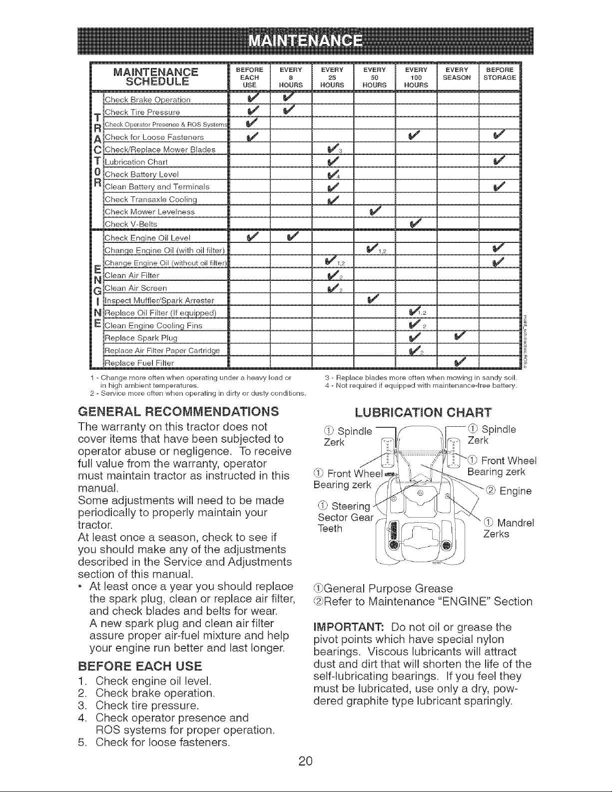
MAINTENANCE
SCHEDULE
Sheck Brake Operation
Sheck Tire Pressure
T
R Check Operator Presence & ROS System_
A Sheck for Loose Fasteners
C ShecWBeplace Mower Blades
T Lubrication Chart
0 Sheck Battery Level
.Clean Battery and Terminals
.Check Transaxle Cooling
,Check Mower Levelness
.Check V-Belts
,Check Enqine Oil Level
,Chan_e Engine Oil (with oil filter}
Change Engine Oil /without oil filtel
_ `clean Air Filter
G ,Clean Air Screen
nspect Muffler/Spark Arrester
H qeplace Oil Filter (If equipped)
E ,Clean Engine Cooling Fins
qeplace Spark Plug
:_eplace Air Filter Paper Cartridge
qeplace Fue! Filter
BEFORE
EACH
USE
EVERY
8
HOURS
J
1 - Change more often when operating under a heavy load or
in high ambient temperatures,
2 - Service more often when operating in dirty or dusty conditions.
EVERY
25
HOURS
_1,2
EVERY
50
HOURS
_1,2
J
EVERY
100
HOURS
J
J
i
_,2
EVERY BEFORE
SEASON STORAGE
3 - Replace blades more often when mowing in sandy soil.
4 - Not required if equipped with maintenance-tree battery.
GENERAL RECOMMENDATmONS
The warranty on this tractor does not
cover items that have been subjected to
operator abuse or negligence. To receive
full value from the warranty, operator
must maintain tractor as instructed in this
manual.
Some adjustments writ need to be made
periodically to properly maintain your
tractor.
At least once a season, check to see if
you should make any of the adjustments
described in the Service and Adjustments
section of this manual.
At least once a year you should replace
the spark plug, clean or replace air filter,
and check blades and belts for wear.
A new spark plug and clean air filter
assure proper air-fuel mixture and help
your engine run better and last longer.
BEFORE EACH USE
1. Check engine oil level.
2. Check brake operation.
3. Check tire pressure.
4. Check operator presence and
ROS systems for proper operation.
5. Check for loose fasteners.
LUBRICATmON CHART
_!_ Spindle -- Spindle
Zerk Zerk
_!_ Front Wheel
Bearing zerk
Front Wheel
Bearing zerk
@ Engine
_!-_Steerinc
Sector Gear _!_ Mandrel
Teeth Zerks
_!-_General Purpose Grease
@Refer to Maintenance "ENGINE" Section
IMPORTANT: Do not oil or grease the
pivot points which have special nylon
bearings. Viscous lubricants will attract
dust and dirt that will shorten the life of the
self-lubricating bearings. If you feel they
must be lubricated, use only a dry, pow-
dered graphite type lubricant sparingly.
20
TRACTOR
Always observe safety rules when per-
forming any maintenance.
BRAKE OPERATION
if tractor requires more than five (5) feet to
stop at highest speed in highest gear on a
level, dry concrete or paved surface, then
brake must be serviced. (See "TO CHECK
BRAKE" in the Service and Adjustments
section of this manual).
TIRES
* Maintain proper air pressure in all tires
(See PSI on tires).
, Keep tires free of gasoline, oil, or insect
control chemicals which can harm rub-
ber.
, Avoid stumps, stones, deep ruts, sharp
objects and other hazards that may
cause tire damage.
NOTE: To seal tire punctures and prevent
flat tires due to slow leaks, tire sealant
may be purchased from your local parts
dealer. Tire sealant also prevents tire dry
rot and corrosion.
OPERATOR PRESENCE SYSTEM AND
REVERSE OPERATION SYSTEM (ROS)
Be sure operator presence and reverse
operation systems are working properly. If
your tractor does not function as de-
scribed, repair the problem immediately.
o The engine should not start unless the
brake pedal is fully depressed, and the
attachment clutch control is in the disen-
gaged position.
CHECK OPERATOR PRESENCE
SYSTEM
When the engine is running, any at-
tempt by the operator to leave the seat
without first setting the parking brake
should shut off the engine.
When the engine is running and the
attachment clutch is engaged, any at-
tempt by the operator to leave the seat
should shut off the engine.
The attachment clutch should never op-
erate unless the operator is in the seat.
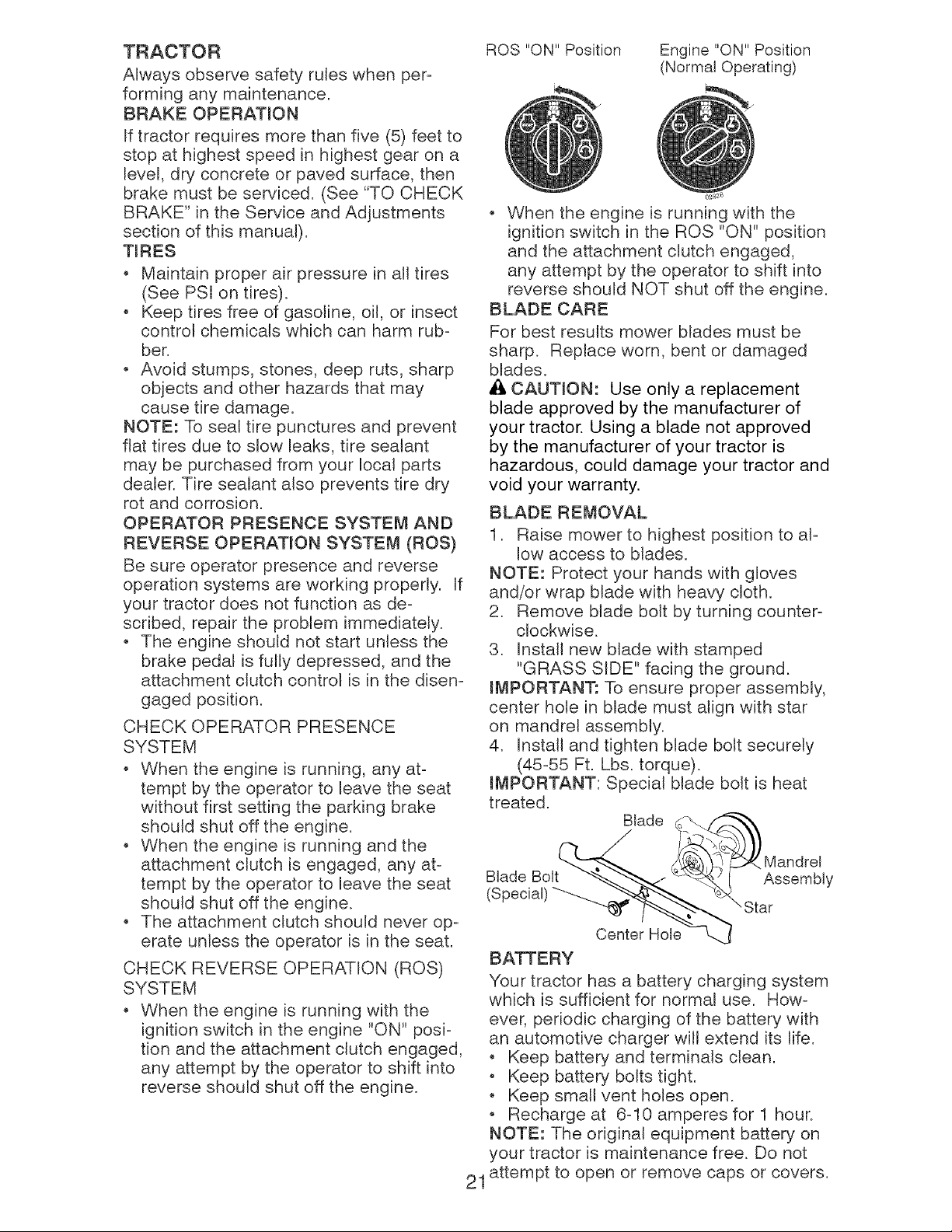
CHECK REVERSE OPERATION (ROS)
SYSTEM
When the engine is running with the
ignition switch in the engine "ON" posi-
tion and the attachment clutch engaged,
any attempt by the operator to shift into
reverse should shut off the engine.
ROS "ON" Position
Engine "ON" Position
(Normal Operating)
When the engine is running with the
ignition switch in the ROS "ON" position
and the attachment clutch engaged,
any attempt by the operator to shift into
reverse should NOT shut off the engine.
BLADE CARE
For best results mower Nades must be
sharp. Replace worn, bent or damaged
blades.
A CAUTION: Use only a replacement
blade approved by the manufacturer of
your tractor. Using a blade not approved
by the manufacturer of your tractor is
hazardous, could damage your tractor and
void your warranty.
BLADE REMOVAL
1. Raise mower to highest position to al-
low access to blades.
NOTE: Protect your hands with gloves
and/or wrap Made with heavy cloth.
2. Remove blade bolt by turning counter-
clockwise.
3. Install new blade with stamped
"GRASS S_DE" facing the ground.
IMPORTANT: To ensure proper assembly,
center hole in blade must align with star
on mandrel assemMy.
4. Install and tighten blade bolt securely
(45-55 Ft. Lbs. torque).
mMPORTANT: Special blade bolt is heat
treated.
Blade
Blade Bolt Assembly
(Special)
"" Star
21
Center Hole
BATTERY
Your tractor has a battery charging system
which is sufficient for normal use. How-
ever, periodic charging of the battery with
an automotive charger will extend its life.
Keep battery and terminals clean.
o Keep battery bolts tight.
Keep small vent hoUes open.
o Recharge at 6-10 amperes for 1 hour.
NOTE: The original equipment battery on
your tractor is maintenance free. Do not
attempt to open or remove caps or covers.
Adding or checking level of electrolyte is
not necessary.
TO CLEAN BATTERY AND TERMINALS
Corrosion and dirt on the battery and
terminals can cause the battery to "leak"
power.
1. Disconnect BLACK battery cable first
then RED battery cable and remove
battery from tractor.
2. Rinse the battery with plain water and
dry.
3. Clean terminals and battery cable ends
with wire brush until bright.
4. Coat terminals with grease or petro-
leum jelly.
5. Reinstall battery (See"REPLACING
BATTERY" in the SERVICE AND AD-
JUSTMENTS section of this manual).
TRANSAXLE COOLING
The transmission fan and cooling fins
should be kept clean to assure proper
cooling.
Do not attempt to clean fan or transmis-
sion while engine is running or while the
transmission is hot. To prevent possible
damage to seals, do not use high pressure
water or steam to clean transaxle.
Inspect cooling fan to be sure fan blades
are intact and clean.
Inspect cooling fins for dirt, grass clip-
pings and other materials. To prevent
damage to seals, do not use com-
pressed air or high pressure sprayer to
clean cooling fins.
TRANSAXLE PUMP FLUID
The transaxle was sealed at the factory
and fluid maintenance is not required for
the life of the transaxle. Should the trans-
axle ever leak or require servicing, contact
your nearest Sears or other qualified
service center.
V-BELTS
Check V-belts for deterioration and wear
after 100 hours of operation and replace
if necessary. The belts are not adjustable.
Replace belts if they begin to slip from
wear.
LUBRICATION
Only use high quality detergent oit rated
with API service classification SG-SL.
Select the oil's SAE viscosity grade
according to your expected operating
temperature.
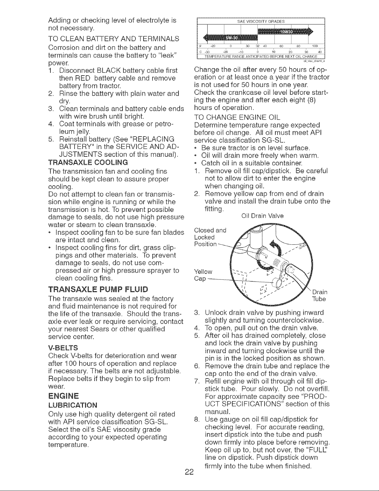
_; SAE VISCOSITY GRADES
-20 0 30 32 40 60 80 100
-._o -2o -1; o 1'o _o ._o 4;
TEMPERATURE RANGE ANTICIPATED BEFORE NEXT OIL CHANGE
oil v_,_ chad4 e
Change the oil after every 50 hours of op-
eration or at least once a year if the tractor
is not used for 50 hours in one year.
Check the crankcase oit level before start-
ing the engine and after each eight (8)
hours of operation.
TO CHANGE ENGINE OIL
Determine temperature range expected
before oil change. AH oil must meet API
service classification SG-SL
, Be sure tractor is on level surface.
, Oi} will drain more freely when warm.
, Catch oil in a suitable container.
1. Remove oit fill cap/dipstick. Be careful
not to allow dirt to enter the engine
when changing oil.
2. Remove yellow cap from end of drain
valve and install the drain tube onto the
fitting.
Oil Drain Valve
Closed and
Locked
Yellow
Cap
22
Drain
Tube
3. Unlock drain valve by pushing inward
slightly and turning counterclockwise.
4. To open, pull out on the drain valve.
5. After oit has drained completely, close
and lock the drain valve by pushing
inward and turning clockwise until the
pin is in the locked position as shown.
6. Remove the drain tube and replace the
cap onto the end of the drain valve.
7. Refill engine with oil through oil fill dip-
stick tube. Pour slowly. Do not overfill.
For approximate capacity see "PROD-
UCT SPECIFICATIONS" section of this
manual.
8. Use gauge on oil fill cap/dipstick for
checking level. For accurate reading,
insert dipstick into the tube and push
down firmly into place before removing.
Keep oil up to, but not over, the "FULl"
line on dipstick. Push dipstick down
firmly into the tube when finished.

AIR FILTER
Your engine will not run properly using
a dirty air filter. Service papercartridge
every two months or every 25 hours of
operation, whichever occursfirst.
Service paper cartridge more often under
dusty conditions.
Replacethe papercartridge annually,or
after every 100 hours of operation.
TO SERVICE CARTRIDGE
+ Replace a dirty, bent, or damagedcar-
tridge. Handlenew cartridge carefully;
do not use if the rubberseal is dam-
aged.
NOTE: Do not wash the paper cartridge
or use pressurizedair,as this will damage
the cartridge.
1. Open door (A) on the blower housing
to access the air cleaner element (B).
2. Unhookthe latch (C)and remove the
element.
3. Gently tap the paper elementto dis-
lodge dirt.
4. Clean all air cleaner componentsof
any accumulated dirt or foreign mate-
rial. Prevent any dirt from entering the
throat of carburetor.
5. Install cleaned or new element on the
base and secure with latch.
6. Close and latch the door.
CLEAN AIR SCREEN
Air screen must be keptfree of dirt and
chaff to prevent engine damage from
overheating. Clean with a wire brush or
compressed air to remove dirt and stub-
born dried gum fibers.
CLEAN AIR INTAKE!COOUNG AREAS
To insure proper cooling, make sure the
grass screen, cooling fins, and other exter-
nal surfaces of the engine are kept clean
at all times.
Every 100 hours of operation (more often
underextremely dusty, dirty conditions),
removethe blower housing and other cool-
ing shrouds. Clean the cooling fins and
external surfaces as necessary.Make sure
the cooling shrouds are reinstalled.
NOTE: Operatingthe engine with a
blocked grass screen, dirty or plugged
cooling fins, and/or cooling shrouds
removedwill cause engine damage due to
overheating.
MUFFLER
Inspectand replace corroded mufflerand
spark arrester (if equipped) as it could cre-
ate a fire hazard and/or damage.
SPARK PLUG(S)
Replacespark plug(s) at the beginning
of each mowing season or after every
100 hours of operation,whichever occurs
first. Sparkplug type and gap setting are
shown in "PRODUCTSPECIFICATIONS"
section of this manual.
mN-UNEFUEL FILTER
The fuel filter should be replaced once
each season. Iffuel filter becomes
clogged, obstructingfuel flow to carbu-
retor,replacementis required.
1. With engine cool, removefilter and
plug fuel line sections.
2. PUacenewfuel filter in position in fuel
line with arrow pointingtowards carbu-
retor.
3. Be sure there are no fuel line leaks and
clamps are properly positioned.
4. Immediatelywipe up any spilled gaso-
line. Clamp--....
Fuel
23
Clean engine, battery, seat, finish, etc.
of all foreign matter.
Keep finished surfaces and wheels free
of all gasoline, oil, etc.
o Protect painted surfaces with auto-
motive type wax.
We do not recommend using a garden
hose or pressure washer to clean your
tractor unless the engine and transmis-
sion are covered to keep water out. Water
in engine or transmission will shorten the
useful life of your tractor. Use compressed
air or a leaf blower to remove grass,
leaves and trash from tractor and mower.
WARNING: TO AVOID SERIOUS INJURY, BEFORE PERFORMING ANY SER-VICE OR ADJUSTMENTS:
1. Depress brake pedal fully and set parking brake.
2. Place attachment clutch in "DISENGAGED" position.
3. Turn ignition key to "STOP" and remove key.
4. Make sure the blades and all moving parts have completely stopped.
5. Disconnect spark plug wire from spark plug and place wire where it cannot
come in contact with plug.
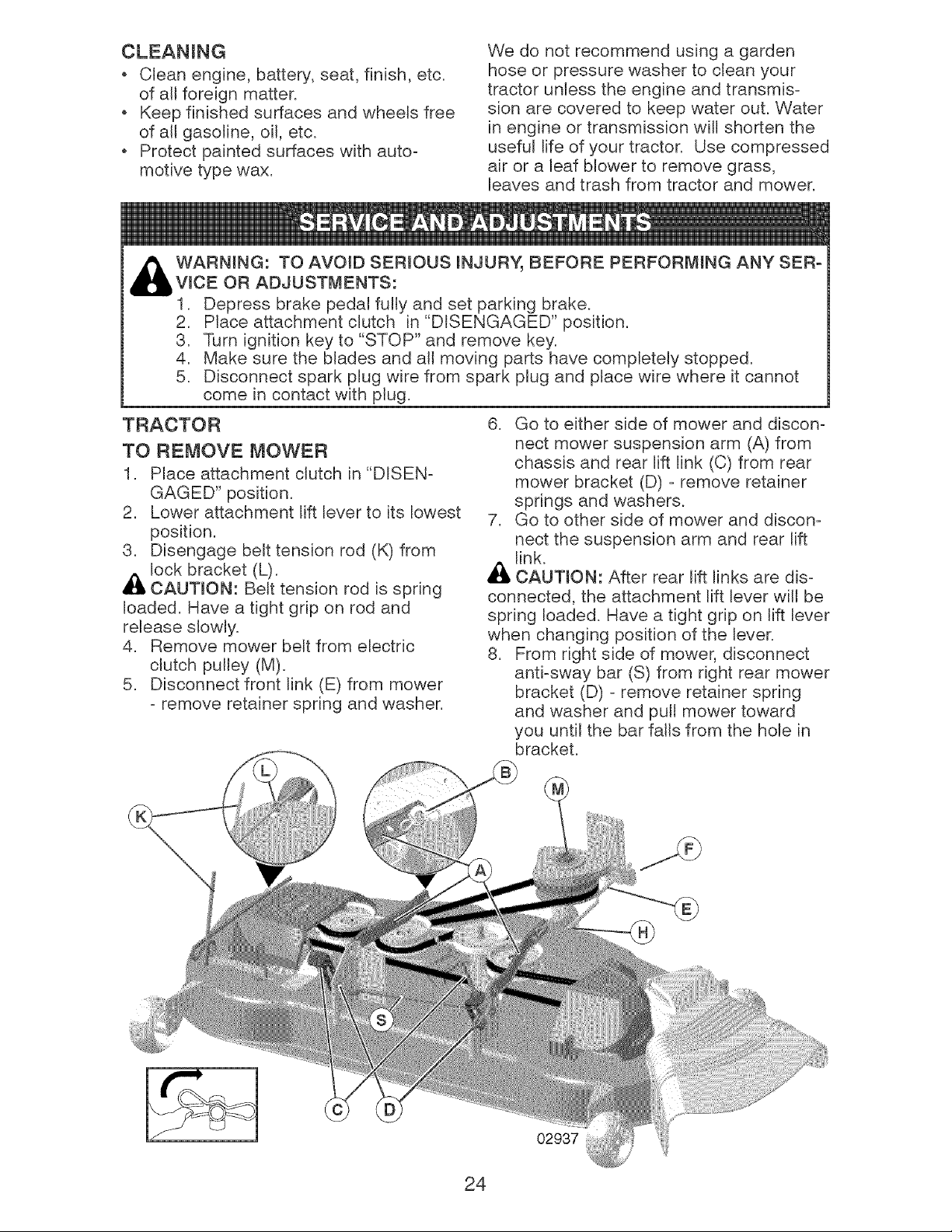
TRACTOR
TO REMOVE MOWER
1. Place attachment clutch in "DISEN-
GAGED" position.
2. Lower attachment lift lever to its lowest
position.
3. Disengage belt tension rod (K) from
lock bracket (L).
_I, CAUTION: Belt tension rod is spring
loaded. Have a tight grip on rod and
release slowly.
4. Remove mower belt from electric
clutch pulley (M).
5. Disconnect front link (E) from mower
- remove retainer spring and washer.
6. Go to either side of mower and discon-
nect mower suspension arm (A) from
chassis and rear lift link (C) from rear
mower bracket (D) - remove retainer
springs and washers.
7. Go to other side of mower and discon-
nect the suspension arm and rear lift
Al_ link.
CAUTION: After rear lift links are dis-
connected, the attachment lift lever will be
spring loaded. Have a tight grip on lift lever
when changing position of the lever.
8. From right side of mower, disconnect
anti-sway bar (S) from right rear mower
bracket (D) - remove retainer spring
and washer and pull mower toward
you until the bar falls from the hole in
bracket.
02937
24
9. Turn tractor steering wheel to the left
as far as it will go.
10. Slide mower out from under right side
of tractor.
TO INSTALL MOWER
Follow procedure described in "INSTALL
MOWER AND DR_VE BELT" in the As-
sembly section of this manual.
TO LEVEL MOWER
Make sure tires are properly inflated to
the PSI shown on tires. If tires are over
or under inflated, it may affect the appear-
ance of your lawn and lead you to think
the mower is not adjusted properly.
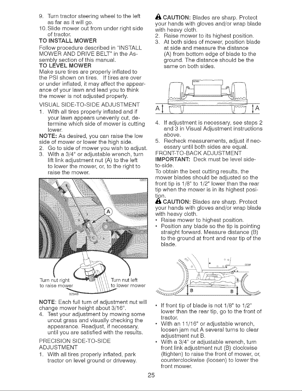
VISUAL SIDE-TO-SIDE ADJUSTMENT
1. With at1 tires properly inflated and if
your lawn appears unevenly cut, de-
termine which side of mower is cutting
lower.
NOTE: As desired, you can raise the low
side of mower or lower the high side.
2. Go to side of mower you wish to adjust.
3. With a 3/4" or adjustable wrench, turn
lift link adjustment nut (A) to the left
to lower the mower, or, to the right to
raise the mower.
02933
_IL CAUTION: Blades are sharp. Protect
your hands with gloves and/or wrap blade
with heavy cloth.
2. Raise mower to its highest position.
3. At both sides of mower, position blade
at side and measure the distance
(A) from bottom edge of Made to the
ground. The distance should be the
same on both sides.
AI 1J :21A
4. If adjustment is necessary, see steps 2
and 3 in Visual Adjustment instructions
above.
5. Recheck measurements, adjust if nec-
essary until both sides are equal
FRONT-TO-BACK ADJUSTMENT
iMPORTANT: Deck must be level side-
to-side.
To obtain the best cutting results, the
mower blades should be adjusted so the
front tip is 1/8" to 1/2" lower than the rear
tip when the mower is in its highest posi-
tion.
_i_ CAUTION: Blades are sharp. Protect
your hands with gloves and/or wrap blade
with heavy cloth.
Raise mower to highest position.
Position any blade so the tip is pointing
straight forward. Measure distance (B)
to the ground at front and rear tip of the
blade.
Turn nut right
to raise mower
Turn nut left
to lower mower
02948
NOTE: Each full turn of adjustment nut will
change mower height about 3/16".
4. Test your adjustment by mowing some
uncut grass and visually checking the
appearance. Readjust, if necessary,
until you are satisfied with the results.
PRECISION SIDE-TO-SIDE
ADJUSTMENT
1. With all tires properly inflated, park
tractor on level ground or driveway.
25
If front tip of blade is not 1/8" to 1/2"
lower than the rear tip, go to the front of
tractor.
With an 11/16" or adjustable wrench,
loosen jam nut A several turns to clear
adjustment nut B.
With a 3/4" or adjustable wrench, turn
front link adjustment nut (B) clockwise
(Itighten) to raise the front of mower, or,
counterclockwise (loosen) to lower the
front mower.
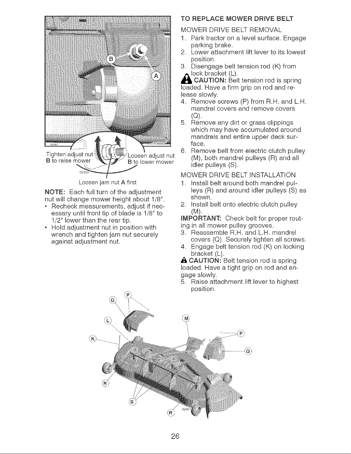
Tighten adjust nut
B to raise mower
Loosen adjust nut
B to lower mower
Loosen jam nut A first
NOTE: Each full turn of the adjustment
nut will change mower height about 1/8".
+ Recheck measurements, adjust if nec-
essary until front tip of blade is 1/8" to
1/2" lower than the rear tip.
. Hold adjustment nut in position with
wrench and tighten jam nut securely
against adjustment nut.
TO REPLACE MOWER DRIVE BELT
MOWER DRIVE BELT REMOVAL
1. Park tractor on a level surface. Engage
parking brake.
2. Lower attachment lift lever to its lowest
position.
3. Disengage belt tension rod (K) from
_l_ock bracket (L).
CAUTmON: Belt tension rod is spring
loaded. Have a firm grip on rod and re-
lease slowly.
4. Remove screws (P) from R.H. and LH.
mandrel covers and remove covers
(Q).
5. Remove any dirt or grass clippings
which may have accumulated around
mandrels and entire upper deck sur-
face.
6. Remove belt from electric clutch pulley
(M), both mandrel pulleys (R) and all
idler pulleys (S).
MOWER DRIVE BELT INSTALLATION
1. Install belt around both mandrel pul-
leys (R) and around idler pulleys (S) as
shown.
2. Install belt onto electric clutch pulley
(M).
IMPORTANT: Check belt for proper rout-
ing in all mower pulley grooves.
3. Reassemble R.H. and LH. mandrel
covers (Q). Securely tighten all screws.
4. Engage belt tension rod (K) on locking
bracket (L).
_, CAUTION: Belt tension rod is spring
loaded. Have a tight grip on rod and en-
gage slowly.
5. Raise attachment lift lever to highest
position.
26
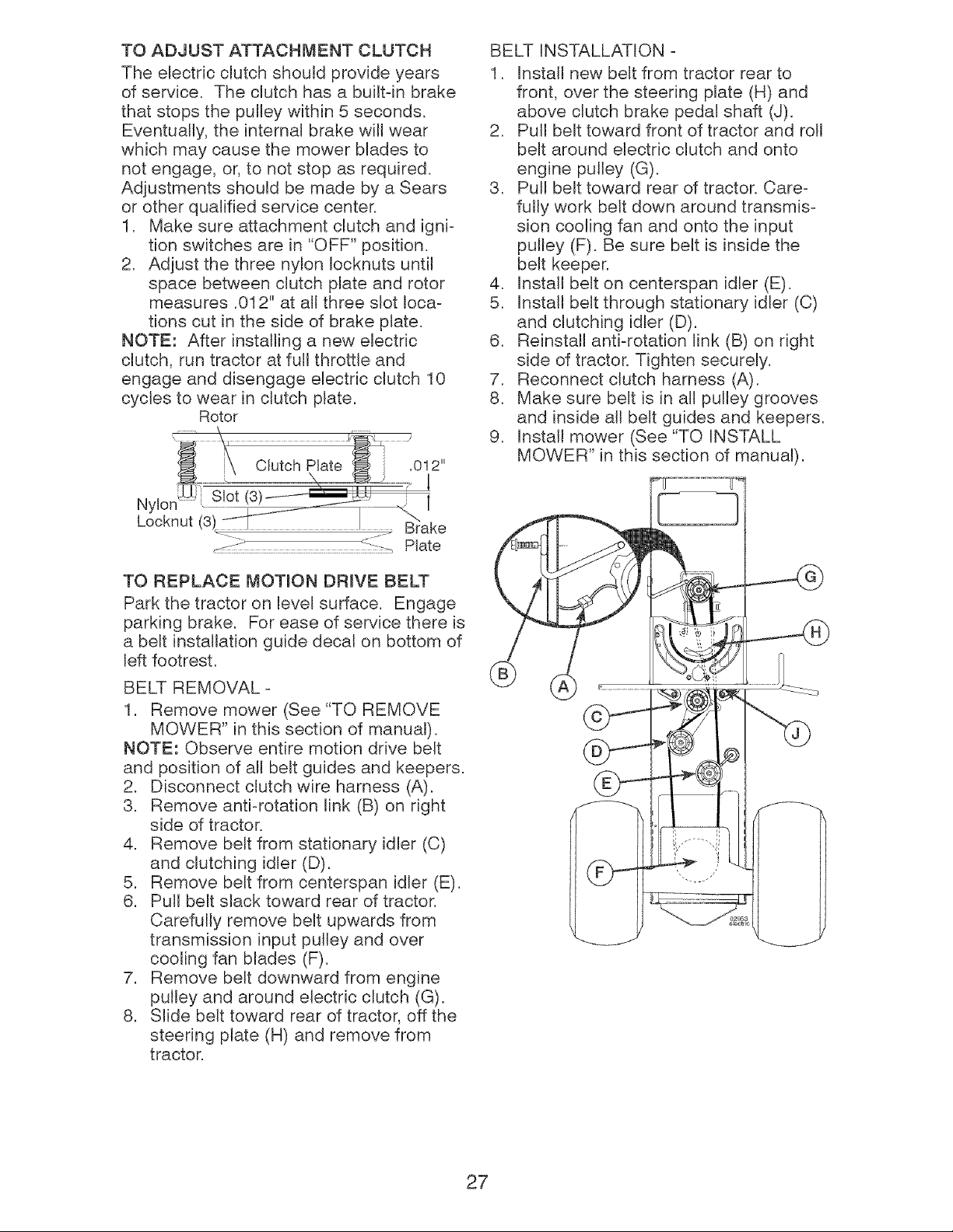
TO ADJUST ATTACHMENT CLUTCH
The electric clutch should provide years
of service. The clutch has a builtqn brake
that stops the pulley within 5 seconds.
Eventually, the internal brake will wear
which may cause the mower blades to
not engage, or, to not stop as reqwred.
Adjustments should be made by a Sears
or other quaIMed service center.
1. Make sure attachment clutch and igni-
tion switches are in "OFF" position.
2. Adjust the three nylon Iocknuts until
space between clutch plate and rotor
measures .012" at all three slot loca-
tions cut in the side of brake plate.
NOTE: After installing a new electric
clutch, run tractor at full throttle and
engage and disengage electric clutch 10
cycles to wear in clutch plate.
Rotor
.012"
1
Nylon_i Slot (3)
1
Locknut
_--- ..........................................................................................L:: :-:_Plate
TO REPLACE MOTION DRIVE BELT
Park the tractor on level surface. Engage
parking brake. For ease of service there is
a belt installation guide decal on bottom of
left footrest.
BELT REMOVAL-
1. Remove mower (See "TO REMOVE
MOWER" in this section of manual).
NOTE: Observe entire motion drive belt
and position of all belt guides and keepers.
2. %sconnect clutch wire harness (A).
3. Remove antiorotation link (B) on right
side of tractor.
4. Remove belt from stationary idler (C)
and clutching idler (D).
5. Remove belt from centerspan idler (E).
6. Pull belt slack toward rear of tractor.
Carefully remove belt upwards from
transmission input pulley and over
cooting fan blades (F).
7. Remove belt downward from engine
pulley and around electric clutch (G).
8. Slide belt toward rear of tractor, off the
steering plate (H) and remove from
tractor.
BELT INSTALLATION -
1. Install new bek from tractor rear to
front, over the steering plate (H) and
above clutch brake pedal shaft (J).
2. Pull belt toward front of tractor and roll
belt around electric clutch and onto
engine pulley (G).
3. Pull belt toward rear of tractor. Care°
fully work belt down around transmis°
sion cooling fan and onto the input
pulley (F). Be sure belt is inside the
belt keeper.
4. Install belt on centerspan idler (E).
5. Install belt through stationary idler (C)
and clutching idler (D).
6. Reinstall antiorotation link (B) on right
side of tractor. Tighten securely.
7. Reconnect clutch harness (A).
8. Make sure belt is in all pulley grooves
and inside all belt guides and keepers.
9. Install mower (See "TO INSTALL
MOWER" in this section of manual).
27
TO CHECK BRAKE
If tractor requires more than five (5) feet to
stop at highest speed in highest gear on a
level, dry concrete or paved surface, then
brake must be serviced.
You may also check brake by:
1. Park tractor on a level, dry concrete or
paved surface, depress clutch/brake
pedal all the way down and engage
parking brake.
2. Disengage transmission by placing
freewheel control in "transmission dis-
engaged" position. Pull freewheel con-
trol out and into the slot and release so
it is held in the disengaged position.
The rear wheels must lock and skid
when you try to manually push the tractor
forward. If the rear wheels rotate, then the
brake needs to be serviced. Contact a
Sears or other qualified service center.
FRONT WHEEL TOE-IN/CAMBER
Your new tractor front wheel toe-in and
camber is set at the factory and is normal.
The front wheel toe-in and camber are
not adjustable. If damage has occurred to
affect the factory set front wheel toe-in or
camber, contact a Sears or other qualified
service center.
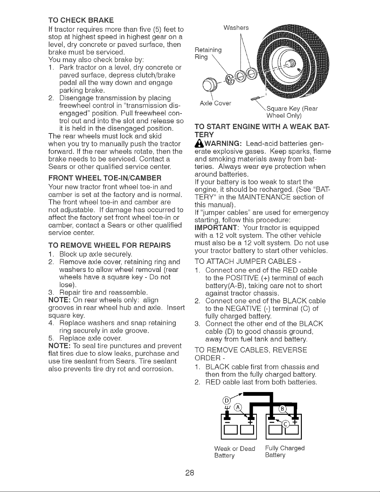
TO REMOVE WHEEL FOR REPAIRS
1. Block up axle securely.
2. Remove axle cover, retaining ring and
washers to allow wheel removal (rear
wheels have a square key - Do not
lose).
3. Repair tire and reassemble.
NOTE: On rear wheels only: align
grooves in rear wheel hub and axle. Insert
square key.
4. Replace washers and snap retaining
ring securely in axle groove.
5. Replace axle cover.
NOTE: To seal tire punctures and prevent
flat tires due to slow leaks, purchase and
use tire sealant from Sears. Tire sealant
also prevents tire dry rot and corrosion.
Washers
Retaining
Ring
o
Axle Cover
I
_'_Square Key (Rear
Wheel Only)
TO START ENGINE WiTH A WEAK BAT-
TERY
_WARNING: Lead-acid batteries gen-
erate explosive gases. Keep sparks, flame
and smoking materials away from bat-
teries. Always wear eye protection when
around batteries.
If your battery is too weak to start the
engine, it should be recharged. (See "BAT-
TERY" in the MA{NTENANCE section of
this manual).
If "jumper cables" are used for emergency
starting, follow this procedure:
mMPORTANT: Your tractor is equipped
with a 12 volt system. The other vehicle
must also be a 12 volt system. Do not use
your tractor battery to start other vehicles.
TO ATTACH JUMPER CABLES -
1. Connect one end of the RED cable
to the POSITIVE (+) terminal of each
battery(A-B), taking care not to short
against tractor chassis.
2. Connect one end of the BLACK came
to the NEGATIVE (-) terminal (C) of
fully charged battery.
3. Connect the other end of the BLACK
cable (D) to good chassis ground,
away from fuel tank and battery.
TO REMOVE CABLES, REVERSE
ORDER -
1. BLACK cable first from chassis and
then from the fully charged battery.
2. RED cable last from both batteries.
Weak or Dead Fully Charged
Battery Battery
28
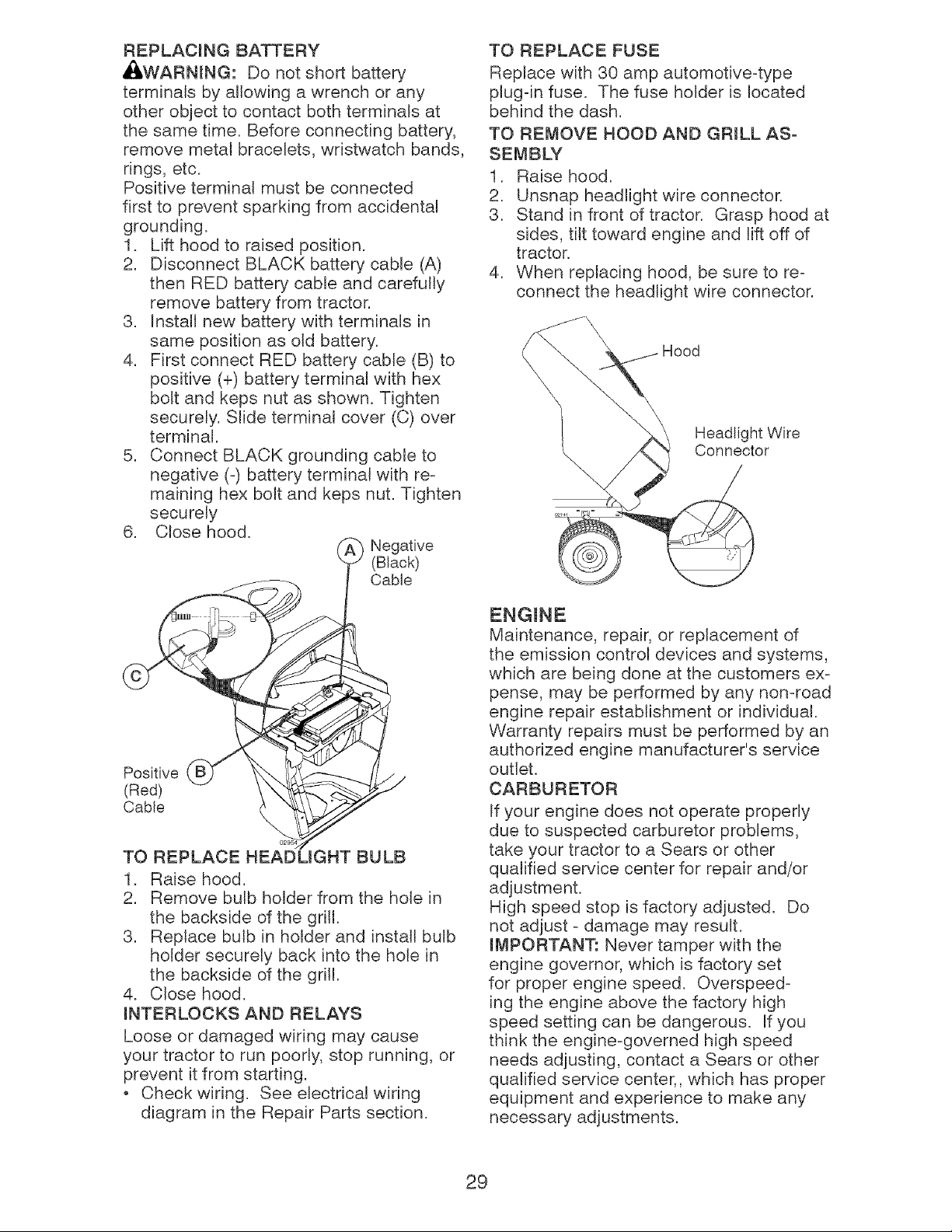
REPLACING BATTERY
_I:_WARNING: Do not short battery
terminals by allowing a wrench or any
other object to contact both terminals at
the same time. Before connecting battery,
remove metal bracelets, wristwatch bands,
rings, etc.
Positive terminal must be connected
first to prevent sparking from accidental
grounding.
1. Lift hood to raised position.
2. Disconnect BLACK battery cable (A)
then RED battery cable and carefully
remove battery from tractor.
3. Instalt new battery with terminals in
same position as old battery.
4. First connect RED battery cable (B) to
positive (+) battery terminal with hex
bolt and keps nut as shown. Tighten
securely. Slide terminal cover (C) over
terminal.
5. Connect BLACK grounding cable to
negative (-) battery terminal with re-
maining hex bolt and keps nut. Tighten
securely
6. Close hood.
Negative
(Black)
Cable
TO REPLACE FUSE
Replace with 30 amp automotive-type
plug-in fuse. The fuse holder is located
behind the dash.
TO REMOVE HOOD AND GRILL AS-
SEMBLY
1. Raise hood.
2. Unsnap headlight wire connector.
3. Stand in front of tractor. Grasp hood at
sides, tilt toward engine and lift off of
tractor.
4. When replacing hood, be sure to re-
connect the headlight wire connector.
Hood
Headlight Wire
Connector
Positive
(Red)
Cable
TO REPLACE HEADLIGHT BULB
1. Raise hood.
2. Remove bulb holder from the hole in
the backside of the grill.
3. Replace bulb in holder and install bulb
holder securely back into the hole in
the backside of the grill.
4. Close hood.
iNTERLOCKS AND RELAYS
Loose or damaged wiring may cause
your tractor to run poorly, stop running, or
prevent it from starting.
Check wiring. See electrical wiring
diagram in the Repair Parts section.
Maintenance, repair, or replacement of
the emission control devices and systems,
which are being done at the customers ex-
pense, may be performed by any non-road
engine repair establishment or individual.
Warranty repairs must be performed by an
authorized engine manufacturer's service
outlet.
CARBURETOR
If your engine does not operate properly
due to suspected carburetor problems,
take your tractor to a Sears or other
qualified service center for repair and/or
adjustment.
High speed stop is factory adjusted. Do
not adjust - damage may result.
IMPORTANT: Never tamper with the
engine governor, which is factory set
for proper engine speed. Overspeed-
ing the engine above the factory high
speed setting can be dangerous. If you
think the engine-governed high speed
needs adjusting, contact a Sears or other
qualified service center,, which has proper
equipment and experience to make any
necessary adjustments.
29
Immediately prepare your tractor for stor-
age at the end of the season or if the trac-
will not be used for 30 days or more.
WARNmNG: Never store the tractor
with gasoline in the tank inside a building
where fumes may reach an open flame
or spark. Allow the engine to cool before
storing in any enclosure.
When tractor is to be stored for a period
of time, clean it thoroughly, remove all dirt,
grease, leaves, etc. Store in a clean, dry
area.
1. Clean entire tractor (See "CLEANING"
in the Maintenance section of this
manual).
2. Inspect and replace belts, if necessary
(See belt replacement instructions in
the Service and Adjustments section of
this manual).
3. Lubricate as shown in the Maintenance
section of this manual.
4. Be sure that all nuts, bolts and screws
are securely fastened. Inspect moving
parts for damage, breakage and wear.
Replace if necessary.
5. Touch up aH rusted or chipped paint
surfaces; sand lightly before painting.
Fully charge the battery for storage.
After a period of time in storage, battery
may require recharging.
To help prevent corrosion and power
leakage during long periods of storage,
battery cables should be disconnected
and battery cleaned thoroughly (see "TO
CLEAN BATTERY AND TERMINALS" in
the Maintenance section of this manual).
After cleaning, leave cables discon-
nected and place cables where they
cannot come in contact with battery
terminals.
If battery is removed from tractor for
storage, do not store battery directly on
concrete or damp surfaces.
FUEL SYSTEM
mMPORTANT: It is important to prevent
gum deposits from forming in essential
fuel system parts such as carburetor, fuel
hose, or tank during storage. Also, alcohol
blended fuels (called gasohol or using
ethanol or methanol) can attract moisture
which leads to separation and formation of
30
acids during storage. Acidic gas can dam-
age the fuel system of an engine while in
storage.
Empty the fuel tank by starting the en-
gine and letting it run unti_ the fuel lines
and carburetor are empty.
Never use engine or carburetor cleaner
products in the fuel tank or permanent
damage may occur.
Use fresh fuel next season.
NOTE: Fuel stabilizer is an acceptaMe
alternative in minimizing the formation of
fuel gum deposits during storage. Add
stabilizer to gasoline in fuel tank or stor-
age container. Always follow the mix ratio
found on stabilizer container. Run engine
at least 10 minutes after adding stabilizer
to allow the stabilizer to reach the carbure-
tor. Do not empty the gas tank and carbu-
retor if using fuel stabilizer.
ENGINE OIL
Drain oi_ (with engine warm) and replace
with clean engine oil. (See "ENGINE" in
the Maintenance section of this manual).
CYUNDER(S)
1. Remove spark plug(s).
2. Pour one ounce of oH through spark
plug hole(s) into cylinder(s).
3. Turn ignition key to start position for a
few seconds to distribute oil.
4. Replace with new spark plug(s).
OTHER
Do not store gasoline from one season
to another.
Replace your gasoline can if your can
starts to rust. Rust and/or dirt in your
gasoline will cause problems.
If possible, store your tractor indoors
and cover it to give protection from dust
and dirt.
Cover your tractor with a suitaMe pro-
tective cover that does not retain mois-
ture. Do not use plastic. Plastic cannot
breathe which allows condensation to
form and will cause your tractor to rust.
mMPORTANT: Never cover tractor while
engine and exhaust areas are still warm.
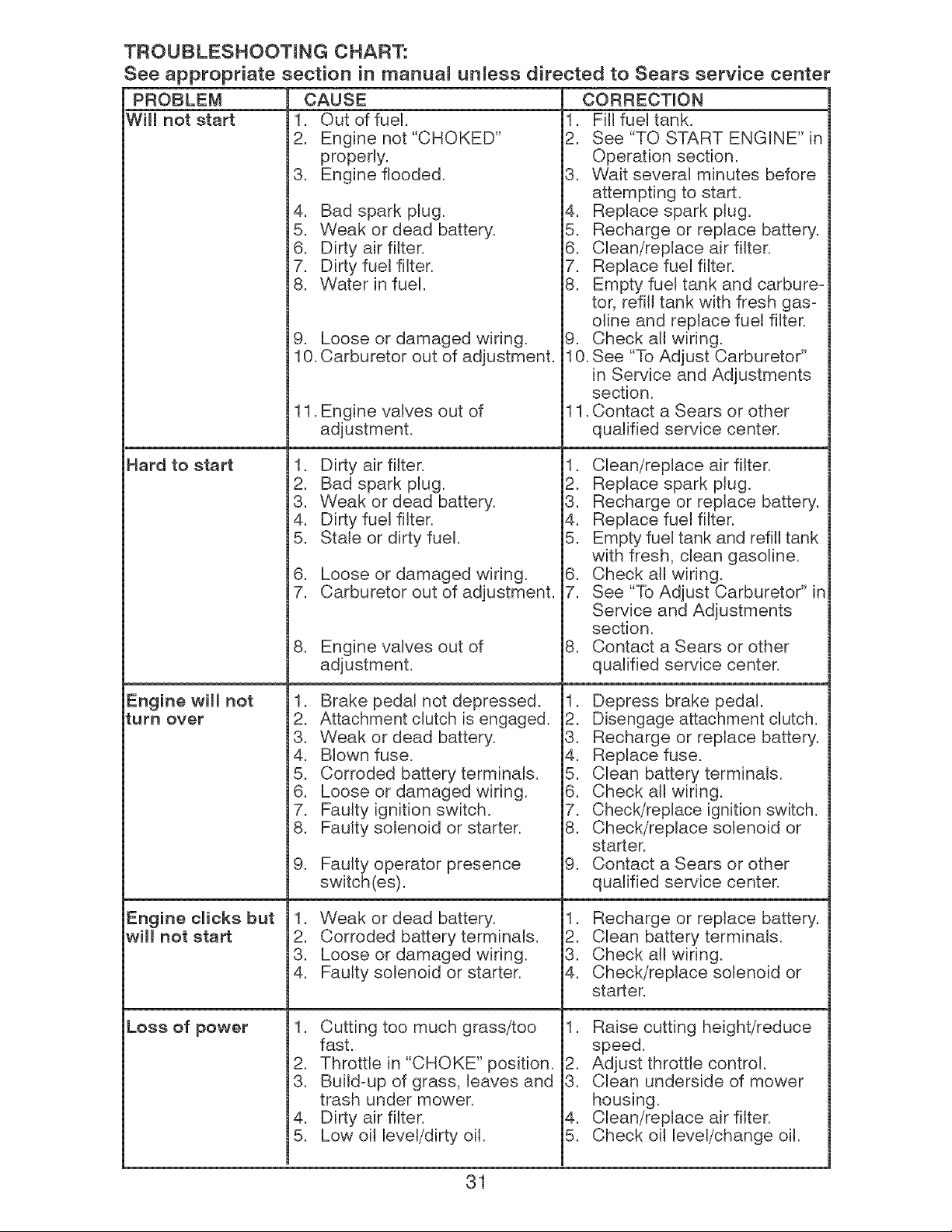
TROUBLESHOOTING CHART:
See appropriate section in manual unless directed to Sears service center
PROBLEM
W[[[ not start
Hard to start
Engine will not
turn over
Engine clicks but
will not start
Loss of power
CAUSE
1. Out of fuel.
2. Engine not "CHOKED"
properly.
3. Engine flooded.
4. Bad spark plug.
5. Weak or dead battery.
6. Dirty air filter.
7. Dirty fuel filter.
8. Water in fuel.
9. Loose or damaged wiring.
10. Carburetor out of adjustment.
11. Engine valves out of
adjustment.
1. Dirty air fitter.
2. Bad spark plug.
3. Weak or dead battery.
4. Dirty fuel filter.
5. Stale or dirty fuel.
6. Loose or damaged wiring.
7. Carburetor out of adjustment.
8. Engine valves out of
adjustment.
1. Brake pedal not depressed.
2. Attachment clutch is engaged.
3. Weak or dead battery.
4. Blown fuse.
5. Corroded battery terminals.
6. Loose or damaged wiring.
7. Faulty ignition switch.
8. Faulty solenoid or starter.
9. Fautty operator presence
switch(es).
1. Weak or dead battery.
2. Corroded battery terminals.
3. Loose or damaged wiring.
4. Faulty solenoid or starter.
1. Cutting too much grass/too
fast.
2. Throttle in "CHOKE" position.
3. Build=up of grass, leaves and
trash under mower.
4. Dirty air filter.
5. Low oil level/dirty oil.
CORRECTION
1. Fill fuel tank.
2. See "TO START ENGINE" in
Operation section.
3. Wait several minutes before
attempting to start.
4. Replace spark plug.
5. Recharge or replace battery.
6. Clean/replace air filter.
7. Replace fuel filter.
8. Empty fuel tank and carbure-
tor, refill tank with fresh gas=
oline and replace fuel filter.
9. Check all wiring.
10. See "To Adjust Carburetor"
in Service and Adjustments
section.
11. Contact a Sears or other
qualified service center.
1. Clean/replace air filter.
2. Replace spark plug.
3. Recharge or replace battery.
4. Replace fuel filter.
5. Empty fuel tank and refill tank
with fresh, clean gasoline.
6. Check at[ wiring.
7. See "To Adjust Carburetor" in
Service and Adjustments
section.
8. Contact a Sears or other
qualified service center.
1. Depress brake pedal.
2. Disengage attachment clutch.
3. Recharge or replace battery.
4. Replace fuse.
5. Clean battery terminals.
6. Check atl wiring.
7. Check/replace ignition switch.
8. Check/replace solenoid or
starter.
9. Contact a Sears or other
qualified service center.
1. Recharge or replace battery.
2. Clean battery terminals.
3. Check all wiring.
4. Check/replace solenoid or
starter.
1. Raise cutting height/reduce
speed.
2. Adjust throttle control.
3. Clean underside of mower
housing.
4. Clean/replace air filter.
5. Check oil level/change oil.
31
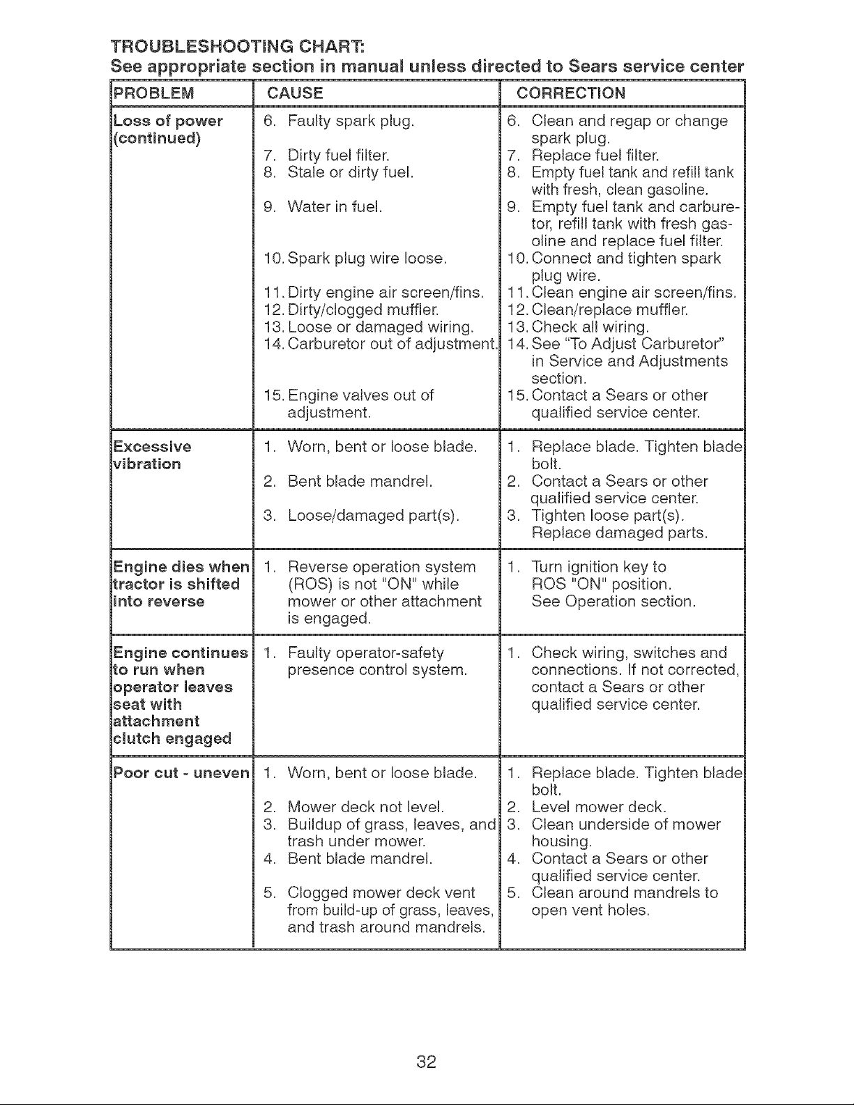
TROUBLESHOOTING CHART:
See appropriate section in manual unless directed to Sears service center
PROBLEM CORRECTION
Loss of power
(continued)
Engine dies when
tractor is shifted
into reverse
Engine continues
to run when
operator leaves
seat with
attachment
¢mutch engaged
Poor cut - uneven
CAUSE
6. Faulty spark plug.
7. Dirty fuel filter.
8. Stale or dirty fuel.
9. Water in fuel.
10. Spark plug wire loose.
11. Dirty engine air screen/fins.
12. Dirty/clogged muffler.
13. Loose or damaged wiring.
14. Carburetor out of adjustment.
15. Engine valves out of
adjustment.
1. Worn, bent or loose blade.
2. Bent blade mandrel.
3. Loose/damaged part(s).
,
Reverse operation system
(ROS) is not "ON" while
mower or other attachment
is engaged.
1. Faulty operator-safety
presence control system.
,
2.
3.
4.
5.
Worn, bent or loose Made.
Mower deck not level.
Buildup of grass, leaves, and
trash under mower.
Bent blade mandrel.
Clogged mower deck vent
from build-up of grass, leaves,
and trash around mandrels.
6. Clean and regap or change
spark pJug.
7. Replace fuel fitter.
8. Empty fuel tank and refill tank
with fresh, clean gasoline.
9. Empty fuel tank and carbure-
tor, refill tank with fresh gas-
oline and replace fuel filter.
10. Connect and tighten spark
plug wire.
11. Clean engine air screen/fins.
12. Clean/replace muffler.
13. Check all wiring.
14. See "To Adjust Carburetor"
in Service and Adjustments
section.
15. Contact a Sears or other
qualified service center.
1. Replace blade. Tighten blade
bolt.
2. Contact a Sears or other
qualified service center.
3. Tighten loose part(s).
Replace damaged parts.
,
,
Turn ignition key to
ROS "ON" position.
See Operation section.
Check wiring, switches and
connections. If not corrected,
contact a Sears or other
qualified service center.
1. Replace Made. Tighten blade
bolt.
2. Level mower deck.
3. Clean underside of mower
housing.
4. Contact a Sears or other
qualified service center.
5. Clean around mandrels to
open vent holes.
32
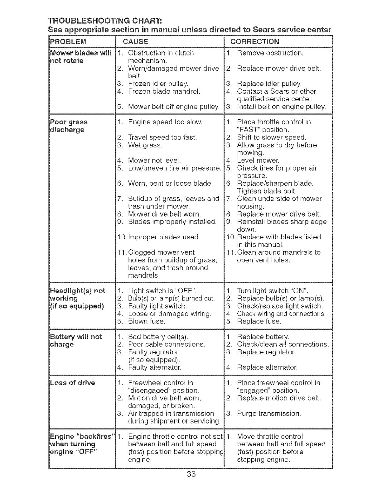
TROUBLESHOOTING CHART:
See appropriate section in manuam unless directed to Sears service center
PROBLEM CAUSE CORRECTION
1. Remove obstruction.Mower blades will
not rotate
Poor grass
discharge
Headlight(s) not
working
(if so equipped)
Battery will not
charge
Loss of drive
Engine "backfires'
when turning
engine "OFF"
1. Obstruction in clutch
mechanism.
2. Worn/damaged mower drive
belt.
3. Frozen idler pulley.
4. Frozen blade mandrel.
5. Mower belt off engine pulley.
1. Engine speed too slow.
2. Travel speed too fast.
3. Wet grass.
4. Mower not level.
5. Low/uneven tire air pressure.
6. Worn, bent or loose blade.
7. Buildup of grass, leaves and
trash under mower.
8. Mower drive belt worn.
9. Blades improperly installed.
10. Improper blades used.
11.
Clogged mower vent
holes from buildup of grass,
leaves, and trash around
mandrels.
1. Light switch is "OFF".
2. Bulb(s) or lamp(s) burned out.
3. Faulty light switch.
4. Loose or damaged wiring.
5. Blown fuse.
1. Bad battery celt(s).
2. Poor came connections.
3. Faulty regulator
(if so equipped).
4. Faulty alternator.
1. Freewheel control in
"disengaged" position.
2. Motion drive belt worn,
damaged, or broken.
3. Air trapped in transmission
during shipment or servicing.
,
Engine throttle control not set
between half and full speed
(fast) position before stopping
engine.
2. Replace mower drive belt.
3. Replace idler pulley.
4. Contact a Sears or other
qualified service center.
3. Install belt on engine pulley.
1. Place throttle control in
"FAST" position.
2. Shift to slower speed.
3. Allow grass to dry before
mowing.
4. Level mower.
5. Check tires for proper air
pressure.
6. Replace/sharpen Made.
Tighten blade bolt.
7. Clean underside of mower
housing.
8. Replace mower drive belt.
9. Reinstall Mades sharp edge
down.
10. Replace with blades listed
in this manual.
11. Clean around mandrels to
open vent holes.
1. Turn light switch "ON".
2. Replace bulb(s) or lamp(s).
3. Check/replace light switch.
4. Check wiring and connections.
5. Replace fuse.
1. Replace battery.
2. Check/clean all connections.
3. Replace regulator.
4. Replace alternator.
1. Place freewheel control in
"engaged" position.
2. Replace motion drive belt.
3. Purge transmission.
, Move throttle control
between half and full speed
(fast) position before
stopping engine.
33
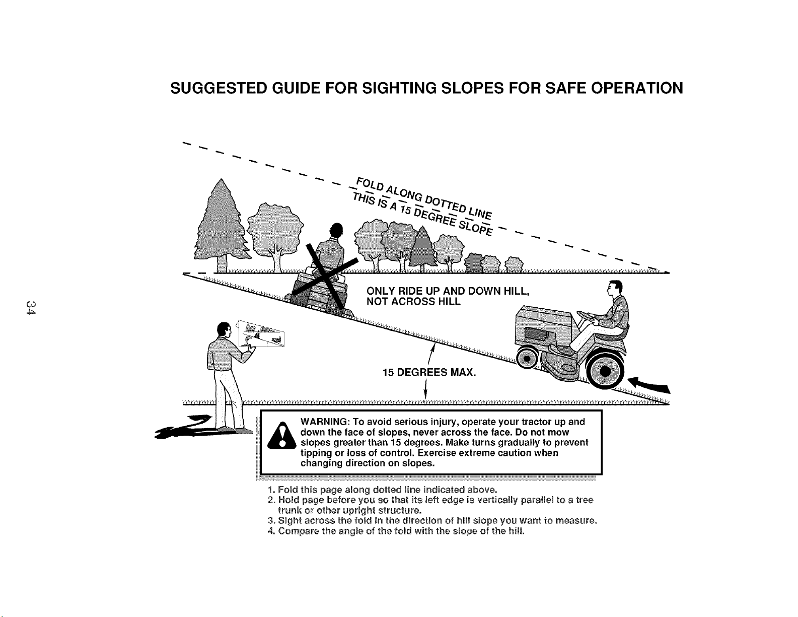
SUGGESTED GUIDE FOR SIGHTING SLOPES FOR SAFE OPERATION
ONLY RIDE UP AND DOWN HILL,
NOT ACROSS HILL
15 DEGREES MAX.
_ ARNING: To avoid serious injury, operate your tractor up and
down the face of slopes, never across the face. Do not mow
slopes greater than 15 degrees. Make turns gradually to prevent
tipping or loss of control. Exercise extreme caution when
changing direction on slopes.
t. Fold this page along dotted line indicated above.
2. Hotd page before you so that its left edge is vertically paratie_ to a tree
trunk or other upright structure.
3. Sight across the fotd in the direction of hill slope you want to measure.
4. Compare the angle of the fold with the slope of the hill.
Servicio y Ajustes ........................................ 57
Almacenamiento .......................................... 63
Identificaci6n de Problemas ........................ 64
Servicio Sears ................................ Contratapa
Partes de Repuesto ........ Vea el Manual Ingles
Ingles del Due_io
GARANTiA LmMITADA PARA EL TRACTOR Y LA BATERiA CRAFTSMAN
2 ANOS PARA EL TRACTOR
Siempre que su uso y mantenimiento se realicen de acuerdo alas instrucciones del Manual del
Qperador, si este tractor Ilega a fallar debido a un defecto de materiales o de fabricaci6n dentro
de un plazo de dos (2) afios a partir de la fecha de compra, Ilame al 1-800-4-MY-HOME®, o bien
gestione una reparaci6n sin cargo.
Durante los primeros 30 d[as de dicho plazo, no se le cobrar& nada pot reparar el producto en su
domicilio. Para su conveniencia, podr& seguir contando con la posibilidad de obtener el service de
la garantfa a domicilio una vez transcurridos los primeros 30 d[as, pero en ese caso deber& pagar
un vi&tico. Usted podr& evitarse el costo del vi&tico si Ileva el producto a un centro de servicios
autorizado de Craftsman. Para saber cual le queda m&s cerca, Ilame al 1°800°4°MY-HOME®.
La cobertura de la garant[a del tractor no incluye:
. Aquellos elementos fungibles que se desgasten pot el uso normal, incluidos, de manera no
taxativa, las cuchillas, buj[as, filtros de aire, correas y filtros de aceite.
. Los servicios de mantenimiento est&ndar, cambios de aceite o ajustes de motor.
. Los cambios o reparaciones de neumaticos pinchados pot objetos extra_os, tales como clavos,
espinas, tocones o trozos de vidrio.
. Las reparaciones que sea preciso hacer debido a malas tecnicas de manejo pot parte del
operador, entre las que se incluyen, de manera no taxativa, los da_os causados par arrastrar
objetos yendo m&s all& de la capacidad del tractor, el choque con objetos que tuerzan el marco
o el eje del cigOe_al, o la aceleraci6n excesiva del motor.
. Las reparaciones que sea preciso hacer debido a la negligencia del operador, entre las que
se incluyen, de manera no taxativa, los da_os electricos y mec&nicos pot guardar la unidad
de manera incorrecta, la no utilizaci6n del grado y la calidad apropiados de aceite para motor,
el no mantener el piso libre de restos y escombros que puedan entrar en combusti6n, o el no
mantener el equipo de acuerdo alas instrucciones del manual del operador.
. Las limpiezas o reparaciones del motor (sistema de combustible) que sea preciso hacer porque
se prueba que el combustible est& contaminado u oxidado (pasado). En general, se debe utili-
zar el combustible dentro de los 30 dfas posteriores a su fecha de compra.
. El deterioro y desgaste normales de las terminaciones exteriores, o la sustituci6n de las etiqu-
etas del producto.
. La bater[a, la cual est& cubierta pot s61o 90 d[as, come se establece a continuaci6n.
90 DiAS PARA LA BATERiA
Por un plazo de noventa (90) dfas a partir de la fecha de compra, si la baterfa que viene con este
tractor presenta algOn defecto de materiales o de fabricaci6n (al probarla, comprobamos que no
mantiene la carga), le set& reemplazada sin costo.
Durante los primeros 30 dias a partir de la compra, no se le cobrar& por realizar el reemplazo de la
baterfa en su domicilio. Para su conveniencia, podr& seguir contando con la posibilidad de obtener
el servicio de la garantfa a domicilio, pero en ese caso, deber& pagar un vi&tico. Usted podr& evio
tarse el costo del vi&tico si Ileva la baterfa a un Centre de Servicios autorizado de Craftsman. Para
saber cu&l le queda m&s cerca, Ilame al 1-800-4-MY-HOME®.
La totalidad de la cobertura de la garantfa del tractor y la baterfa quedar& sin efecto en caso que el
producto sea utilizado con fines comerciales o de alquiler.
La presente garantfa s61o ser& aplicable si el producto se encuentra dentro de los Estados Unidos.
La presente garantfa le otorga derechos legales espec[ficos. Par otra parte, puede que usted
tenga otros derechos, los cuales varfan de estado a estado.
Sears, Roebuck and Co., Hoffmar_ Estates, IL 60179
35
,_PELJGRO: Eeta Maquina cortadora es capaz de amputar masmanosy mospies y de manzar
objetos, ei no se observan lae inetruccionee de eeguridad eiguientee ee pueden producir
leeiones graves o la muerte°
_ADVERTENCIA: Siempre deeconecte el
alambre de la buj[a y p6ngalo donde no pueda
entrar en contacto con la buj[a, para evitar el
arranque pot accidente, durante la preparaci6n,
el transporte, el ajuste o cuando se hacen
reparaciones.
_DVERTENOJA: No avance cuesta abajo a
punto muerto ya que podr[a perder el control
del tractor.
_IADVERTENOIA: Remolque solamente los
accesorios recomendados y conformes alas
caracter[sticas indicadas pot el fabricante de
su tractor. Tenga cuidado y prudencia al utilizar
el tractor. Cuando se encuentre en un declive,
oper utilizando exclusivamente la velocidad
m&s baja. En case de un decWe una carga ex=
cesiva podria resultar peligrosa. Los neum&ti=
cos pueden perder la tracci6n con el suelo y
hacede perder el control de su tractor.
_ADVERTENOIA: El tube de escape del
motor, algunos de sus constituyentes y algunos
componentes del vehiculo contienen o despren=
den productos quimicos conocidos en el Estado
de California como causa de cancer y defectos
al nacimiento u otros dafios reproductivos.
_IADVERTENOIA: Los bornes, terminales y
accesorios relativos de la bater[a contienen
plomo o compuestos de plomo, productos
quimicos conocidos en el Estado de California
como causa de c&ncer y defectos al nacimiento
u otros dafios reproductivos. Lavar las manos
deepu6e de rnanipularloe.
I. FUNCIONAIVIIENTO GENERAL
. Leer, entender y seguir todas las instruccio=
nes sobre la maquina yen el manual antes
de empezar.
No poner las manes o los pies cerca de
partes giratorias o debajo de la m#.quina.
mantener siempre limpia la abertura de
descarga.
Permitir el funcionamiento de la maquina
s61o a adultos que tengan familiaridad con
las instrucciones.
Limpiar el &tea de objetos como piedras,
juguetes, cables, etc. que pueden set recogi-
dos y disparados con las cuchillas.
Asegurarse de que el area este libre de otras
personas antes de poneda en marcha. Parar
la m&quina si alguien entra en el area.
Nunca Ilevar pasajeros.
No cortar marcha atras al no set absolu=
tamente necesario. Mirar siempre abajo y
delante mientras se procede atr&s.
Nunca dirigir el material descargado hacia
nadie. Evitar descargar material contra
paredes u obstrucciones. El material podr[a
rebotar hacia el operador, Parar las cuchillas
cuando se pasan superficies de grava.
36
o No hacer funcionar la maquina sin el
captador de hierba entera, la protecci6n de
descarga u otros dispositivos de seguridad
en su lugar y en buenas condiciones.
Ralentizar antes de girar,
Nunca dejar una maquina encendida sin vigi-
lancia. Apagar siempre las cuchillas, poner el
freno de estacionamiento, parar el motor, y
quitar las Ilaves antes de bajar.
Desconectar las cuchillas cuando no se
corta. Apagar el motor y esperar que todas
las partes esten completamente paradas
antes de Iimpiar la maquina, quitar el capta=
dot de hierba, o desatascar la protecci6n de
descarga.
Hacer funcionar la maquina s61o con la luz
del dia o luz artificial buena.
No hacer funcionar la maquina estando bajo
los efectos de alcohol o droga.
Poner atenci6n al trafico cuando se opera
cerca de calles o se cruzan.
Porter la maxima atenci6n al cargar o descar=
gar la maquina en una caravana o cami6n.
Uevar siempre gafas de protecci6n cuando
se hace funcionar la maquina.
Los datos indican que los operadores a
partir de los 60 ahos estan afectados per
un gran porcentaje de heridas relativas a la
conducci6n del cortacesped. Estos opera=
dotes tendr[an que evaluar su habilidad de
hacer funcionar el cortacesped de modo Io
bastante seguro para proteger a s[ mismos y
a otras personas de heridas graves.
Seguir las recomendaciones del fabricante
para los pesos y contrapesos de las ruedas.
Mantener la m&quina libre de hierba, hojas
u otros escombros que pueden tocar el
tubo de escape / partes del motor calientes
y quemarse. No permitir que el puente del
cortacesped cargue hojas u otros residuos
que pueden causar acumulaciones. Limpiar
toda salpicadura de aceite o carburante an=
tes de hacer operaciones sobre la m&quina o
guardarla. Dejarla enfriar antes de guardada.
il. FUNCIONAMIENTO EN PENDIENTES
Las pendientes son el mayor factor de acciden=
tes relativos a la perdida de control y vuelco,
que pueden causar severas heridas o muerte.
El funcionamiento en pendientes requiere una
atenci6n extra. Si no es posible hacer marcha
atr&s en una pendiente o si te sientes inco=
modo, no la cortes.
Cortar hacia arriba y abajo de una pendiente,
no de modo horizontal.
Porter atenciones a los hoyos, las raices, los
bultos, las piedras u otros objetos escort=
didos. El terreno irregular puede volcar la
ma.quina. La hierba alta puede esconder
obst&culos.
Escogerunavelocidadde marchabajade
modoquenoseanecesariopararseo cam-
biarestandoenunapendiente.
Nocortarla hierbamojada.Lasruedas
puedenperdertracci6n.
Portersiempreunamarchacuandoseest&
enpendientes.Noponeren puntomuertoe
ir cuestaabajo.
Evitararrancar,pararseogirarenuna
pendiente.Silasruedaspierdentracci6n,
desconectarlascuchillasy procederdespa-
ciocuestaabajoenla pendiente.
Mantenertodolosmovimientosenlaspen-
dienteslentosy gradual.Nohacercambios
repentinosdevelocidado direcci6n,yaque
puedencausarel escapede la m6.quina.
Porterla maximaatenci6ncuandola m#.-
quinafuncionaconcaptadoresdehierba
uotrosdispositivosenganchados;pueden
afectarla estabilidaddela maquina.Nousar
enpendientesempinados.
Nointentarestabilizarla maquinaponiendo
el pieenelterreno.
Nocortarcercade bajadas,cunetasy orillas.
Lasm#.quinapuedevolcarseimprovisamente
siunaruedaestaen el bordeo sehunde.
Ill. NINOS
Si el operador no pone atenci6n a la presencia
de los niF_ospueden ocurrir accidentes tragicos.
Los ni_os a menudo estan atraidos pot la mao
quina y las actividad de cortar, No dar por hecho
de que los niBos se queden adonde estaban la
Oltima vez que los vistes.
Mantener los ni_ios fuera del &tea de corte y
vigilados por un adulto responsable que no
sea el operador.
. Estar alerta y apagar la maquina si un ni_os
entra en el area.
Antes y durante la marcha atras, mirar adeJ-
ante y abajo para vet si hay nihos peque_os.
Nunca Ilevar ni_os, incluso si hay las
cuchillas apagadas. Podrfan caer y herirse
seriamente o interferir con el funcionamiento
seguro de la m&quina, los ni_os que se han
Ilevado precedentemente pueden aparecer
de pronto en el &tea de corte por otro paseo
y ser atropellados o tumbados por la ma-
quina.
Nunca dejar que los ni_os manipulen la
m#.quina.
. Tenet el m&ximo cuidado cuando se acerca
a cantos ciegos, arbustos, arboles u otros
objetos que pueden impedir la vista de ni_os.
IV. REMOLQUE
* Remolcar s61o con una m&quina que tenga
un gancho dise_ado para remolcar. En-
ganchar el equipo o remolcar s61o en el
punto dispuesto al efecto.
. Seguir las recomendaciones del productor
con respecto a los limites del equipo por
remolcar y el remolque en pendientes.
Nunca permitir que nihos u otras personas
esten dentro del equipo pot remolcar.
En pendientes, el peso del equipo remolcado
puede causar la p@rdida de tracci6n y la
p@rdida de control.
Viajar despacio y dejar mas distancia para
frenar.
V. SERVlCIO
MANIPULAOK_N SEGURA DE LA GASOUNA
Para evitar heridas personales o daiios a las
cosas, porter el maximo cuidado a la hora de
manipular la gasolina. La gasolina es extrema-
mente inflamable y los vapores son explosivos.
o Apagar todos los cigarrillos, cigarros, pipas y
otras fuentes de ignici6n.
Usar s61o contenedores para gasolina apro-
bados.
Nunca quitar el tap6n de la gasolina o a_adir
carburante con el motor en march& dejar
enfriar el motor antes del abastecimiento de
la gasolina.
. Nunca abastecer la maquina al interior de un
local.
. Nunca guardar la m&quina o el contenedor
del carburante donde haya una llama abierta,
chispas o una luz piloto como un calentador
de agua u otros dispositivos.
. Nunca Ilenar los contenedores al interior de
un vehiculo o en una caravana o cami6n
recubiertos con un forro de pl&stico. Colocar
siempre los contenedores en el terreno lejos
del vehiculo cuando se esta Ilenando.
. Quitar el equipo de gas del cami6n o cara-
vana y abastecedo en el terreno. Si no es
posible, abastecer dicho equipo con un con-
tenedor port&til, m&s bien que de un surtidor
de gasolina.
. Mantener la boquilla a contacto del borde
del dep6sito de carburante o la abertura del
contenedor durante toda la operaci6n de
abastecimiento. No utilizar un dispositivo con
boquilla cerrada-abierta.
. Si se vierte carburante sobre la ropa, cambP
arse la ropa inmediatamente.
. Nunca Ilenar el dep6sito m_.s de Io debido.
Volver a colocar el tap6n del gas y cerrar de
modo firme.
OPERACIONES DE SERViCIO GENERALES
Nunca hacer funcionar la m&quina en un
area cerrada.
Mantener todas las tuercas y pernos apre-
tados para asegurarse de que trabaja en
condiciones seguras.
Nunca modificar los dispositivos de segurP
dad. Controlar su correcto funcionamiento
regularmente.
37
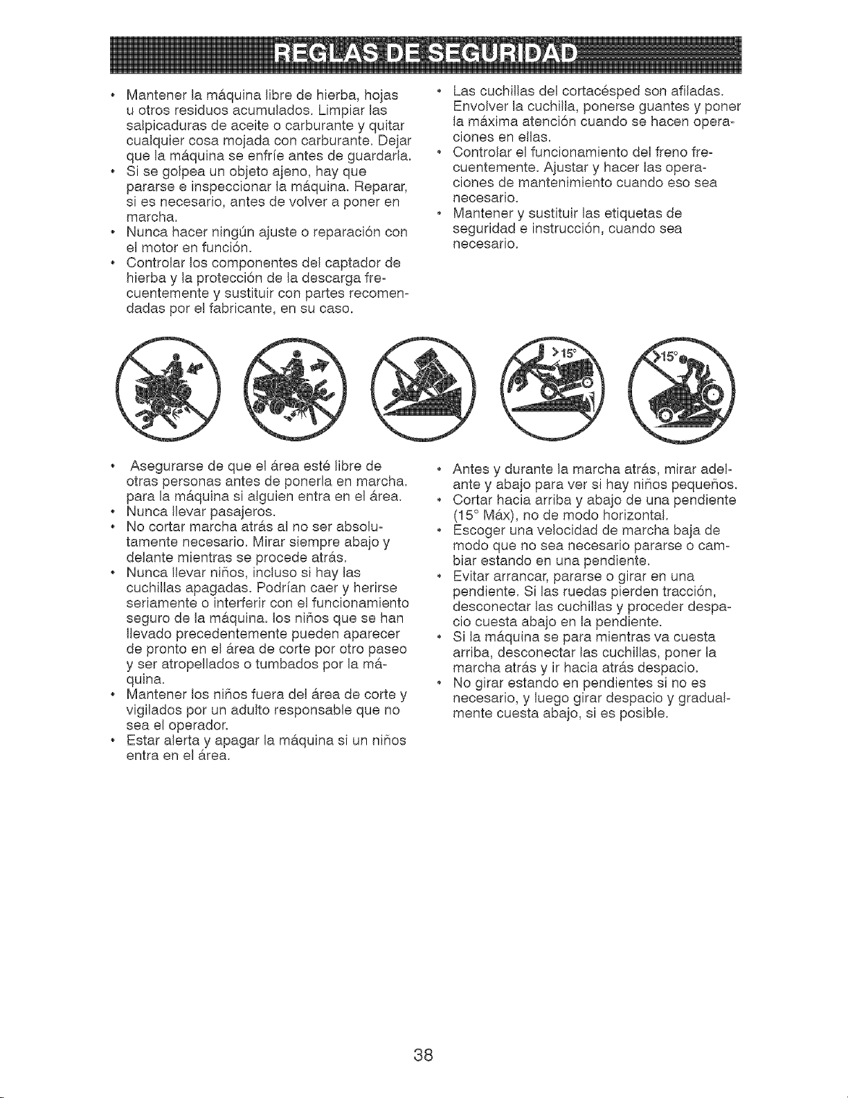
o Mantener la maquina libre de hierba, hojas
u otros residuos acumulados. Limpiar las
salpicaduras de aceite o carburante y quitar
cualquier cosa mojada con carburante. Dejar
que la ma.quina se enfrie antes de guardarla.
Si se golpea un objeto a]eno, hay que
pararse e inspeccionar la m_.quina. Reparar,
si es necesario, antes de volver a poner en
marcha.
Nunca hacer ningOn ajuste o reparaci6n con
el motor en funci6n.
Controlar los componentes del captador de
hierba y la protecci6n de la descarga freo
cuentemente y sustituir con partes recomen-
dadas pot el fabricante, en su caso.
Las cuchillas del cortac@sped son afiladas.
Envolver la cuchilla, ponerse guantes y poner
la m6,xima atenci6n cuando se hacen opera-
ciones en elias.
Controlar el funcionamiento del freno freo
cuentemente. A}ustar y hacer las opera-
ciones de mantenimiento cuando eso sea
necesario.
Mantener y sustituir las etiquetas de
seguridad e instrucci6n, cuando sea
necesario.
o Asegurarse de que el 6.tea est@libre de
otras personas antes de poneda en marcha.
para la maquina si alguien entra en el _.rea.
Nunca Ilevar pasajeros.
No cortar marcha atras al no set absolu-
tamente necesario. Mirar siempre abajo y
delante mientras se precede atr6.s.
Nunca Ilevar nifios, incluso si hay las
cuchillas apagadas. Podrfan caer y herirse
seriamente o interferir con el funcionamiento
seguro de la maquina, los ni_os que se han
Ilevado precedentemente pueden aparecer
de pronto en el 6.tea de corte pot otto paseo
y set atropellados o tumbados pot la mao
quina.
. Mantener los ni_os fuera del area de corte y
vigilados per un adulto responsable que no
sea el operador.
. Estar alerta y apagar la maquina si un ni_os
entra en el area.
Antes y durante la marcha atras, mirar adelo
ante y aba]o para vet si hay ni_ios peque_os.
Cortar hacia arriba y aba]o de una pendiente
(15 ° M6.x), no de modo horizontal.
Escoger una velocidad de marcha baja de
modo que no sea necesario pararse o cam°
biar estando en una pendiente.
Evitar arrancar, pararse o girar en una
pendiente. Si las ruedas pierden tracci6n,
desconectar las cuchillas y proceder despao
cio cuesta aba}o en la pendiente.
Si la maquina se para mientras va cuesta
arriba, desconectar las cuchillas, poner la
No girar estando en pendientes si no es
necesario, y luego girar despacio y gradual-
mente cuesta abajo, si es posible.
38
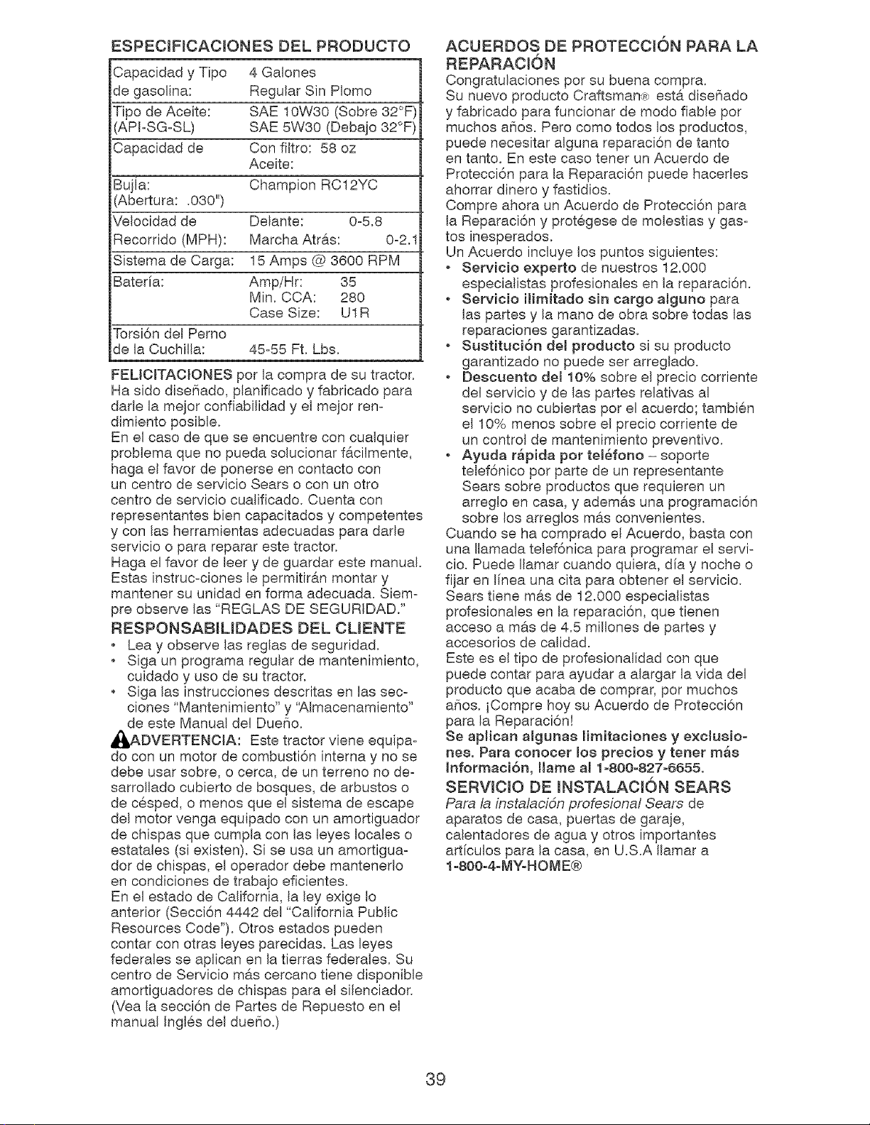
ESPECIHCACJONES DEL PRODUCTO
Capacidad y Tipo 4 Galones
de gasolina: Regular Sin Plomo
Tipo de Aceite: SAE 10W30 (Sobre 32°F)
APFSG-SL) SAE 5W30 (Debajo 32°F)
Capacidad de Con filtro: 58 oz
Aceite:
Bujla: Champion RC12YC
Abertura: .030")
Velocidad de Delante: 0-5.8
Recorrido (MPH): Marcha Atr&s: 0-2.1
Sistema de Carga: 15 Amps @ 3600 RPM
Bateria: Amp/Hr: 35
Min. CCA: 280
Case Size: U1R
Torsi6n del Perno
de la Cuchilla: 45-55 Ft. Lbs.
FELICITACIONES pot la compra de su tractor.
Ha sido disefiado, planificado y fabricado para
dade la mejor confiabilidad y el meier ren-
dimiento posible.
En el caso de que se encuentre con cualquier
problema que no pueda solucionar f&cilmente,
haga el favor de ponerse en contacto con
un centro de servicio Sears o con un otto
centro de servicio cualificado. Cuenta con
representantes bien capacitados y competentes
y con las herramientas adecuadas para dade
servicio o para reparar este tractor.
Haga el favor de leer y de guardar este manual.
Estas instruc-ciones le permitir&n montar y
mantener su unidad en forma adecuada. Siem-
pre observe las "REGLAS DE SEGURIDAD."
RESPONSABJLIDADES DEL CLIENTE
. Lea y observe las reglas de seguridad.
. Siga un programa regular de mantenimiento,
cuidado y uso de su tractor.
Siga las instrucciones descritas en las sec-
clones "Mantenimiento" y '_Jmacenamiento"
de este Manual del DueSo.
_DVERTENOIA: Este tractor viene equipa-
do con un motor de combusti6n interna y no se
debe usar sobre, o cerca, de un terreno no de-
sarrollado cubierto de bosques, de arbustos o
de cesped, o menos que el sistema de escape
del motor venga equipado con un amortiguador
de chispas que cumpla con las leyes locales o
estatales (si existen). Si se usa un amortigua-
dot de chispas, el operador debe mantenerlo
en condiciones de trabajo eficientes.
En el estado de California, la ley exige Io
anterior (Secci6n 4442 del "California Public
Resources Code"). Otros estados pueden
contar con otras leyes parecidas. Las leyes
federales se aplican en la tierras federales. Su
centre de Servicio m&s cercano tiene disponible
amortiguadores de chispas para el silenciador.
(Vea la secci6n de Partes de Repuesto en el
manual Ingles del dueSo.)
ACUERDOS DE PROTECCKDN PARA LA
REPARACI6N
Congratulaciones pot su buena compra.
Su nuevo producto Craftsman<R; est6. diseSado
y fabricado para funcionar de modo fiable par
muchos a_ios. Pero como todos los productos,
puede necesitar alguna reparaci6n de tanto
en tanto. En este caso tenet un Acuerdo de
Protecci6n para la Reparaci6n puede hacerles
ahorrar dinero y fastidios.
Compre ahora un Acuerdo de Protecci6n para
la Reparaci6n y protegese de molestias y gas-
tos inesperados.
Un Acuerdo incluye los puntos siguientes:
Servicio experto de nuestros 12.000
especialistas profesionales en la reparaci6n.
Servicio ilimitado sin cargo alguno para
las partes y la mano de obra sobre todas las
reparaciones garantizadas.
. Sustituci6n del producto si su producto
garantizado no puede set arreglado.
. Descuento de{ 10% sobre el precio corriente
del servicio y de las partes relativas al
servicio no cubiertas pot el acuerdo; tambien
el 10% menos sobre el precio corriente de
un control de mantenimiento preventivo.
, Ayuda r_pida pot telSfono- soporte
telef6nico pot parte de un representante
Sears sobre productos que requieren un
arreglo en casa, y adem&s una programaci6n
sobre los arreglos m&s convenientes.
Cuando se ha comprado el Acuerdo, basta con
una Ilamada telef6nica para programar el servF
cio. Puede Ilamar cuando quiera, dia y noche o
fijar en linea una cita para obtener el servicio.
Sears tiene mas de 12.000 especialistas
profesionales en la reparaci6n, que tienen
acceso a m#.s de 4.5 millones de partes y
accesorios de calidad.
Este es el tipo de profesionalidad con que
puede contar para ayudar a alargar la vida del
producto que acaba de comprar, por muchos
aSos. iCompre hoy su Acuerdo de Protecci6n
para la Reparaci6n!
Se apHcan algunas Hmitaciones y exclusio-
nee. Para conocer mosprecios y tenet m_e
hformaci6n, Hame al 1-800-827-6655,
SERWCJO DE mNSTALACK)N SEARS
Para la insta/acidn profeskma/ Sears de
aparatos de casa, puertas de garaje,
calentadores de agua y otros importantes
art[culos para la casa, en U.S.A Ilamar a
1-800-4-MY-HOME®
39
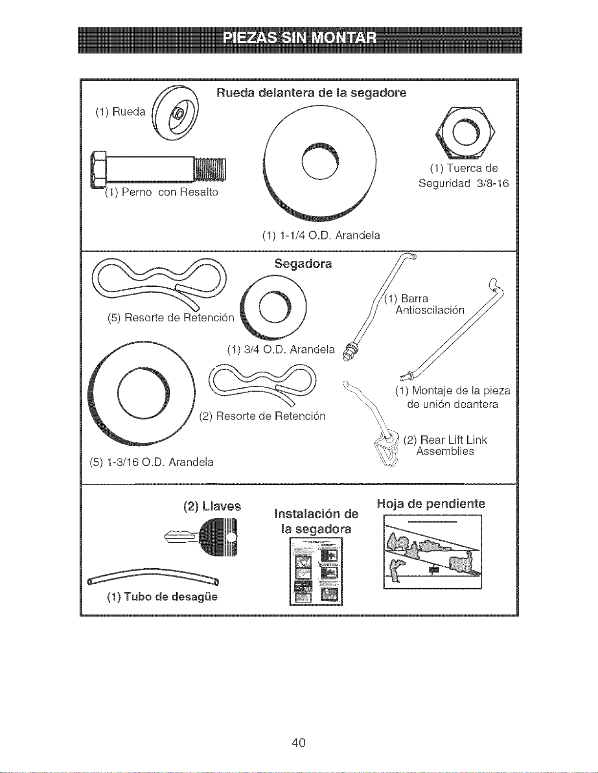
(1) Rueda
1) Pemo con Resalto
Rueda demantera de la segadore
(1) Tuerca de
Seguridad 3/8-16
(1) 1-1/40.D. Arandeia
) Barra
(5) Resorte de Retenci6n Antioscilaci6n
(1) 3/40.D. Arandela
(2) Resorte de Retenci6n
(5) 1-3/16 O.D. Arandela
_ (1) Montaje de la pieza
de uni6n deantera
(2) Rear Lift Link
Assemblies
(2) Lmaves
Hoja de pendiente
(1) Tubo de desagQe
40
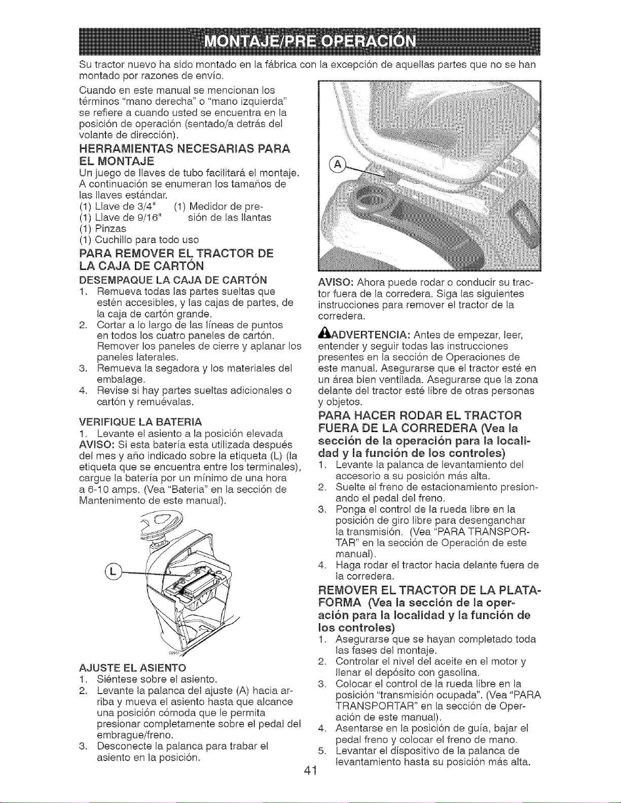
Su tractor nuevo ha sido montado en la f&brica con la excepci6n de aquellas partes que no se han
montado pot razones de env[o.
Cuando en este manual se mencionan los
terminos "mano derecha" o "mano izquierda"
se refiere a cuando usted se encuentra en la
posici6n de operaci6n (sentado/a detras del
volante de direcci6n).
HERRAMIENTAS NECESARIAS PARA
EL MONTAJE
Un juego de Ilaves de tubo facilitar& el montaje.
A continuaci6n se enumeran los tama_ios de
las Ilaves est&ndar.
(1) Llave de 3/4" (1) Medidor de pre-
(1) Llave de 9/16" si6n de las Ilantas
(1) Pinzas
(1) Cuchillo para todo uso
PARA REMOVER EL TRACTOR DE
LA CAJA DE CARTON
DESEMPAQUE LA CAJA DE CARTON
1. Remueva todas las partes sueltas que
esten accesibles, y las cajas de partes, de
la caja de cart6n grande.
2. Cortar a Io largo de las Ifneas de puntos
en todos los cuatro paneles de cart6n.
Remover los paneles de cierre y aplanar los
paneles laterales.
3. Remueva la segadora y los materiales del
embalage.
4. Revise si hay partes sueltas adicionales o
cart6n y remuevalas.
VERIFIQUE LA BATERIA
1. Levante el asiento a la posici6n elevada
AVJSO: Siesta baterfa esta utilizada despues
del mes y a_io indicado sobre la etiqueta (L) (la
etiqueta que se encuentra entre los terminales),
cargue la bateria pot un minimo de una hora
a 6-10 amps. (Vea "Bateria" en la secci6n de
Mantenimento de este manual).
AJUSTE EL ASlENTO
1. Sientese sobre el asiento.
2. Levante la palanca del ajuste (A) hacia ar-
riba y mueva eI asiento hasta que alcance
una posici6n c6moda que le permita
presionar completamente sobre el pedal del
embrague/freno.
3. Desconecte la palanca para trabar el
asiento en la posici6n.
AVISO: Ahora puede rodar o conducir su trac-
tor fuera de la corredera. Siga las siguientes
instrucciones para remover el tractor de la
corredera.
41
_ADVERTENCIA: Antes de empezar, leer,
entender y seguir todas las instrucciones
presentes en la secci6n de Operaciones de
este manual, Asegurarse que el tractor este en
un &tea bien ventilada. Asegurarse que la zona
delante del tractor este libre de otras personas
y objetos.
PARA HACER RODAR EL TRACTOR
FUERA DE LA CORREDERA (Vea la
secci6n de ia operaci6n para la iocaii-
dad y la funci6n de los contromes)
1, Levante la palanca de levantamiento del
accesorio a su posici6n m#.s alta,
2, Suelte el freno de estacionamiento presiom
ando el pedal del freno.
3, Ponga el control de la rueda libre en la
posici6n de giro libre para desenganchar
la transmisi6n. (Vea "PARA TRANSPOR-
TAR" en la secci6n de Operaci6n de este
manual).
4. Haga rodar el tractor hacia delante fuera de
la corredera.
REMOVER EL TRACTOR DE LA PLATA-
FORMA (Vea ia secci6n de la oper-
aci6n para la iocalidad y ia funci6n de
los contromes}
1. Asegurarse que se hayan completado toda
las fases del montaje.
2. Controlar el nivel del aceite en el motor y
Ilenar el dep6sito con gasolina.
3. Colocar el control de la rueda libre en la
posici6n "transmisi6n ocupada". (Vea "PARA
TRANSPORTAR" en la secci6n de Oper-
aci6n de este manual).
4. Asentarse en la posici6n de guia, bajar el
pedal freno y colocar el freno de mano.
5. Levantar el dispositivo de la palanca de
levantamiento hasta su posici6n mas alta.
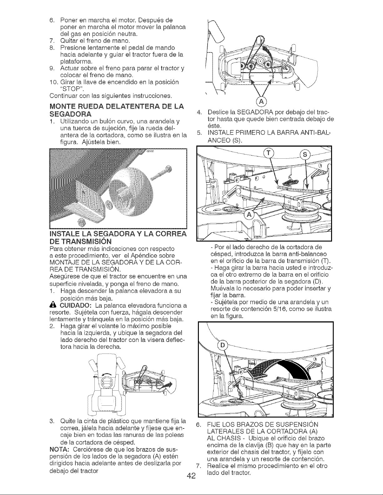
6. Ponerenmarchael motor.Despu@sde
ponerenmarchael motormoverla palanca
delgasenposici6nneutra.
7. Quitarel frenodemano.
8. Presionelentamenteel pedalde mando
haciaadelantey guiareltractorfuerade la
plataforma.
9. Actuarsobreelfrenoparaparareltractory
colocarelfrenodemano.
10.Girarla llavede encendidoen la posici6n
"STOP".
Continuarconlassiguientesinstrucciones.
MONTE RUEDA DELATENTERA DE LA
SEGADORA
1. Utilizando un bul6n curvo, una arandela y
una tuerca de sujeci6n, fije la rueda del-
antera de la cortadora, como se ilustra en la
figura. AjOstela bien.
INSTALE LA SEGADORA Y LA CORREA
DE TRANSMISION
Para obtener m&s indicaciones con respecto
a este procedimiento, vet el Ap@ndice sobre
MONTAJE DE LA SEGADORA Y DE LA COR-
REA DE TRANSMISI©N.
AsegOrese de que el tractor se encuentre en una
superficie nivelada, y ponga el freno de mano.
1. Haga descender la palanca elevadora a su
posici6n mas baja.
OUIDADO: La palanca elevadora funciona a
resorte. Suj@tela con fuerza, h#.gala descender
2. Haga girar el volante Io maximo posible
hacia la izquierda, y ubique la segadora del
lado derecho del tractor con la visera deflec-
tora hacia la derecha.
4. Deslice la SEGADORA pot debajo del trac-
tor hasta que quede bien centrada debajo de
@ste.
5. INSTALE PRIMERO LA BARRA ANTI-BAL-
ANCEO (S).
- Pot el lado derecho de la cortadora de
c@sped, introduzca la barra anti-balanceo
en el orificio de la barra de transmisi6n (T).
- Haga girar la barra hacia usted e introduz-
ca el otto extremo de la barra en el orificio
de la barra posterior de la segadora (D).
Mu@vala Io necesario para poder insertar y
fijar la barra.
- Suj@tela pot medio de una arandela y un
resorte de contenci6n 5/16, como se ilustra
en la figura.
3. Quite la cinta de plAstico que mantiene fija la
correa, j&lela hacia adelante y fijese que en-
caje bien en todas las ranuras de las poleas
de la cortadora de c@sped.
NOTA: Cerci6rese de que los brazos de sus-
pensi6n de los lados de la segadora (A) est@n
dirigidos hacia adelante antes de deslizarla par
debajo del tractor
6,
7,
42
FIJE LOS BRAZOS DE SUSPENSION
LATERALES DE LA CORTADORA (A)
AL CHASIS - Ubique el orificio del brazo
encima de la clavija (B) que hay en la parte
exterior del chasis del tractor, y fijelo con
una arandela y un resorte de contenci6n.
Realice el mismo procedimiento en el otto
lado del tractor.
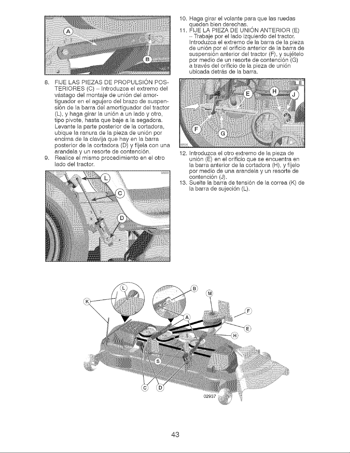
8. FIJELASPEZASDEPROPULSIONPOS-
TERIORES(C)- Introduzcael extremedel
v6.stagodelmonta}ede uni6ndelamor-
tiguadoren elagujerodelbrazode suspen-
si6ndela barradelamortiguadordeltractor
(L),y hagagirarla uni6na unladey otto,
tipopivote,hastaquebajea lasegadora.
Levantela parteposteriorde la cortadora,
ubiquela ranuradela piezadeuni6nper
encimade laclavijaquehayen la barra
posteriorde lacortadora(D)y f[jelaconuna
arandelay un resortedecontenci6n.
9. Realiceel mismoprocedimientoenel otto
ladodeltractor.
10.
11.
Hagagirarelvolanteparaquelasruedas
quedenbienderechas.
FIJELAPIEZADEUNIONANTERIOR(E)
- Trabajepotelladeizquierdodeltractor.
Introduzcaelextremodela barradela pieza
de uni6npot elorificioanteriordela barrade
suspensi6nanteriordeltractor(F),y suj@telo
permediode unresortedecontenci6n(G)
atrav@sdelorificiode lapiezadeuni6n
ubicadadetrasdela barra.
12.Introduzcaelottoextremodela piezade
uni6n(E)enelorificioqueseencuentraen
labarraanteriordelacortadora(H),yf[]elo
potmediodeunaarandelay unresortede
contenci6n(J).
13.Sueltela barradetensi6nde la correa(K)de
labarradesujeci6n(L).
02937
43
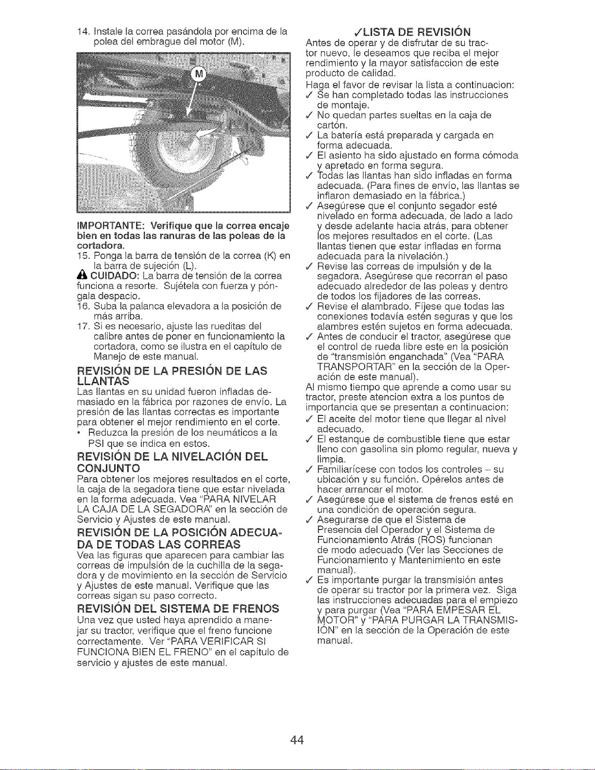
14. Instale la correa pas6,ndoJa pot encima de Ja
polea del embrague del motor (M).
IMPORTANTE: VetifJque que la correa encaje
bien en toda8 la8 ranura8 de lab polea8 de la
cortadora.
15. Ponga la barra de tensi6n de la correa (K) en
la barra de sujeci6n (L).
CUIDADO: La barra de tensi6n de Jacorrea
funciona a resorte. Sujetela con fuerza y p6n=
gala despacio.
16. Suba la paJanca elevadora a la posici6n de
m&s arriba.
17. Si es necesario, ajuste las rueditas del
calibre antes de poner en funcionamiento Ja
cortadora, como se ilustra en el cap[tulo de
Manejo de este manual.
REViSiON DE LA PRESl6N DE LAS
Las Ilantas en su unidad fueron infladas de=
masiado en Ja fabrica pot razones de envfo. La
presi6n de las Ilantas correctas es importante
para obtener el mejor rendimiento en el corte.
Reduzca la presi6n de los neumaticos a la
PSi que se indica en estos.
REVISl6N DE LA NIVELACI6N DEL
CONJUNTO
Para obtener los mejores resultados en el corte,
la caja de la segadora tiene que estar nJvelada
en la forma adecuada. Vea "PARA NIVELAR
LA CAJA DE LA SEGADORA" en la secci6n de
Servicio y Ajustes de este manual.
REViSiON DE LA POS{C{6N ADECUA-
DA DE TODAS LAS CORREAS
Vea las figuras que aparecen para cambiar las
correas de impuJsi6n de la cuchilla de la sega=
dora y de movimJento en la secci6n de Servicio
y Ajustes de este manual. Verifique que las
correas sigan su paso correcto.
REViSiON DEL SlSTEMA DE FRENOS
Una vez que usted haya aprendido a mane-
jar su tractor, verifique que el freno funcione
correctamente. Vet "PARA VERIFICAR SI
FUNCIONA BEN EL FRENO" en el cap[tulo de
servicio y ajustes de este manual.
/LISTA DE REVISl6N
Antes de operar y de disfrutar de su trac-
tor nuevo, le deseamos que reciba el mejor
rendimiento y la mayor satisfaccion de este
producto de calidad.
Haga el favor de revisar la lista a continuacion:
v_ Se Ran completado todas las instrucciones
de montaje.
v_ No quedan partes sueltas en la caja de
cart6n.
v_ La bater[a esta preparada y cargada en
forma adecuada.
v_ El asiento ha sido ajustado en forma c6moda
y apretado en forma segura.
v_ Todas las Ilantas Ran sido infladas en forma
adecuada. (Para fines de envfo, Jas Ilantas se
inflaron demasiado en la fabrica.)
v_ Aseg0rese que el conjunto segador este
nivelado en forma adecuada, de Jado a lado
y desde adelante hacia atras, para obtener
los mejores resultados en el corte. (Las
Ilantas tienen que estar infladas en forma
adecuada para la nivelaci6n.)
v_ Revise las correas de impulsi6n y de la
segadora. Aseg0rese que recorran eJ paso
adecuado alrededor de las poleas y dentro
de todos los fijadores de las correas.
,/ Revise el alambrado. F[jese que todas las
conexiones todavfa esten seguras y que los
alambres esten sujetos en forma adecuada.
,/ Antes de conducir el tractor, aseg0rese que
el control de rueda libre este en la posici6n
de "transmisi6n enganchada" (Vea "PARA
TRANSPORTAR" en la secci6n de la Oper=
aci6n de este manual).
AI mismo tiempo que aprende a como usar su
tractor, preste atencion extra a los puntos de
importancia que se presentan a continuacion:
,/ El aceite del motor tiene que Ilegar al nivel
adecuado.
,/ El estanque de combustible tiene que estar
Jleno con gasoJina sin plomo regular, nueva y
limpia.
,/ Familiaricese con todos los controles - su
ubicaci6n y su funci6n. Operelos antes de
Racer arrancar el motor.
,/Aseg0rese que el sistema de frenos este en
una condici6n de operaci6n segura.
,/Asegurarse de que el Sistema de
Presencia del Operador y el Sistema de
Funcionamiento Atras (ROS) funcionan
de modo adecuado (Vet las Secciones de
Funcionamiento y Mantenlmiento en este
manual).
,/ Es importante purgar la transmisi6n antes
de operar su tractor pot la primera vez. Siga
las instrucciones adecuadas para el empiezo
y para purgar (Vea "PARA EMPESAR EL
_,_OTOR" y "PARA PURGAR LA TRANSMIS-
ION" en la secci6n de la Operaci6n de este
manual.
44
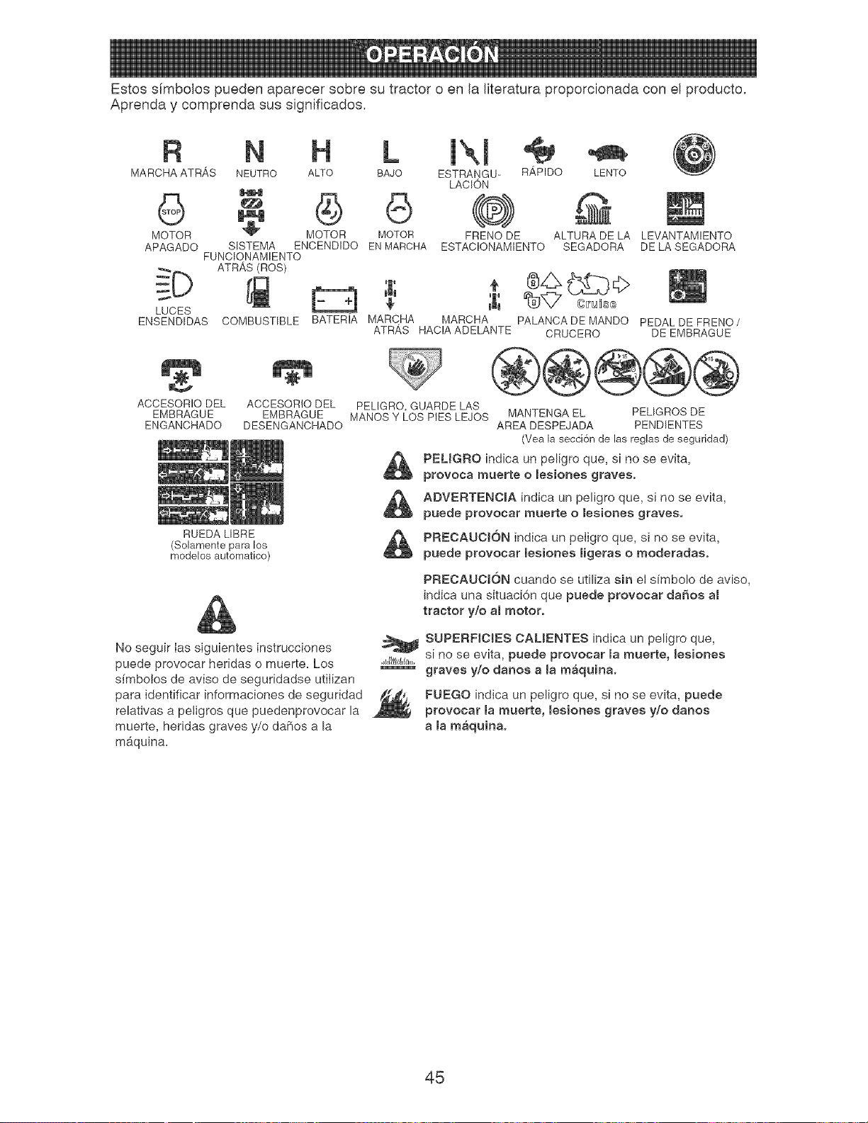
Estos s[mboJos pueden aparecer sobre su tractor o en la literatura proporcionada con el producto,
Aprenda y comprenda sus significados,
R N
MARCHAATRAS NEUTRO ALTO BAJO
G G
MOTOR MOTOR MOTOR
APAGADO SISTEMA ENCENDIDO ENMAROHA
FUNCIONAMIENTO
_D ATRAS (ROS)
LUCES
ENSENDIDAS COMBUSTIBLE BATERIA MARCHA
ATRAS
[
ESTRANGU-
LACION
@)
FRENO DE
ESTAC!ONAMIENTO
R,_PIDO LENTO
ALTURA DELA
SEGADORA
LEVANTAMIENTO
DE LA SEGADORA
MARCHA PALANCADE MANDO PEDALDE FRENO/
HACIAADELANTE CRUCERO DE EMBRAGUE
ACCESORIODEL ACCESORIO DEL
EMBRAGUE EMBRAGUE
ENGANCHADO DESENGANCHADO
RUEDA LIBRE
(Solament÷ para los
modelos automatico)
PELIGRO,GUARDELAS
MANOSY LOS PIES LEJOS MANTENGAEL PELIGROSDE
AREA DESPEJADA PENDENTES
(Vea la secci6nde las reglas de seguridad)
PEUGRO indica un peligro que, si no se evJta,
provoca muerte o lesionee graves.
g ADVERTENOJA indica un peligro que, si no se evita,
puede provocar muerte o leeiones graves.
PREOAUOK_N indica un peiigro que, sl no se evita,
puede provocar lesiones ligeras o moderadas.
PREOAUOI6N cuando se utiliza sin el sfmbolo de aviso,
Jndica una situaci6n que puede provocar da_os al
tractor y/o al motor,
No seguir las siguientes instrucciones
puede provocar heridas o muerte. Los
s[mbolos de aviso de seguridadse utilizan
para identificar informaciones de seguridad
relativas a petigros que puedenprovocar la
muerte, heridas graves y/o daF_osa la
mb,quina.
SUPERFICIES CALiENTES indica un peligro que,
,,_,/ll;_,f_,,,si no se evita, puede provocar [a muerte, mesiones
graves y/o danos ama m_quina,
FUEGO indica an peligro que, si no se evita, puede
provocar la muerte, mesiones graves y/o danos
a [a m_quina,
45
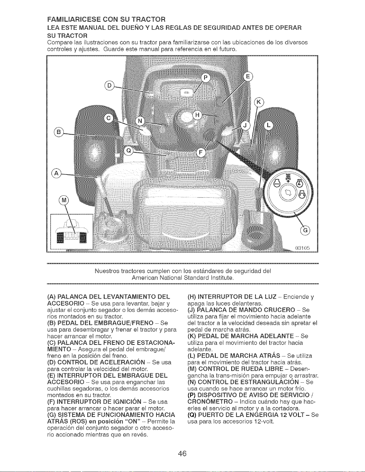
FAMILIARICESE CON SU TRACTOR
LEA ESTE MANUAL DEL DUENO Y LAS REGLAS DE SEGURIDAD ANTES DE OPERAR
SU TRACTOR
Compare las ilustraciones con su tractor para familiarizarse con las ubicaciones de los diversos
controles y ajustes. Guarde este manual para referencia en el futuro.
03105
Nuestros tractores cumplen con los estandares de seguridad del
American National Standard Institute.
(A) PALANCA DEL LEVANTAMIENTO DEL
ACCESORIO - Se usa para levantar, bajar y
ajustar el eonjunto segador o los dem&s aecesoo
tics montados en su tractor.
(B) PEDAL DEL EMBRAGUE/FRENO - Se
usa para desembragar y frenar el tractor y para
Racer arranoar el motor.
(C) PALANOA DEL FRENO DE ESTAOIONA-
MIENTO - Asegura el pedal del embrague/
freno en la posici6n del freno.
(D) CONTROL DE AOELERAOION - Se usa
para controlar la velocidad del motor.
(E) INTERRUPTOR DEL EMBRAGUE DEL
ACOESORIO - Se usa para enganchar las
cuchillas segadoras, o los demas accesorios
montados en su tractor.
(F) INTERRUPTOR DE IGNICION - Se usa
para Racer arrancar o Racer parar el motor.
(G) SJSTEMA DE FUNOIONAMIENTO HAOIA
ATRAS (ROS) en posici6n "ON" - Permite la
operaci6n del conjunto segador o otto acceso-
rio accionado mientras que en reves.
(H) INTERRUPTOR DE LA LUZ - Enciende y
apaga las luces delanteras.
(J) PALANOA DE MANDO CRUCERO - Se
utiliza para fijar el movimiento hacia adelante
del tractor a la velocidad deseada sin apretar el
pedal de marcha atras.
(K) PEDAL DE MARCHA ADELANTE - Se
utiliza para el movimiento del tractor hacia
adelante.
(L) PEDAL DE MARCHA ATRAS - Se utiNza
para el movimiento del tractor hacia atras.
(M) CONTROL DE RUEDA LIBRE - Desen-
gancha la trans-misi6n para empujar q arrastrar.
(N) CONTROL DE ESTRANGULAOION - Se
usa cuando se Race arrancar un motor frio.
(P) DISPOSlTIVO DE AVlSO DE SERVlClO /
ORONOMETRO - Indica cu#.ndo hay que hac-
erles el servicio al motor y a la cortadora.
(Q) PUERTO DE LA ENGERGIA 12 VOLT- Se
usa para los accesorios 12-volt.
46
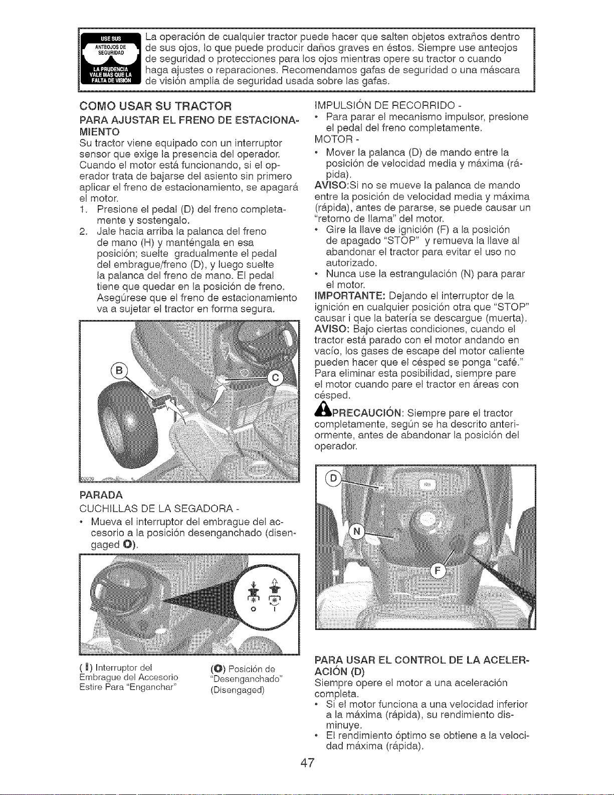
SEGURIDAD
La operaci6n de cualquier tractor puede hacer que salten objetos extra_ios dentro
de sus ojos, Io que puede producir da_ios graves en estos. Siempre use anteojos
de seguridad o protecciones para los ojos mientras opere su tractor o cuando
haga ajustes o reparaciones. Recomendamos gafas de seguridad o una mascara
de visi6n amplia de seguridad usada sobre las gafas.
COMO USAR SU TRACTOR
PARA AJUSTAR EL FRENO DE ESTACIONA-
MIENTO
Su tractor viene equipado con un interruptor
sensor que exige la presencia del operador.
Cuando el motor esta funcionando, si el op-
erador trata de bajarse del asiento sin primero
aplicar el freno de estacionamiento, se apagara
el motor,
1. Presione el pedal (D) del freno completa-
mente y sostengalo.
2. Jale hacia arriba la palanca del freno
de mano (H) y mantengala en esa
posici6n; suelte gradualmente el pedal
del embrague/freno (D), y luego suelte
la palanca del freno de mano, El pedal
tiene que quedar en la posici6n de freno.
AsegOrese que el freno de estacionamiento
va a sujetar el tractor en forma segura.
02939
PARADA
CUCHILLAS DE LA SEGADORA -
. Mueva el interruptor del embrague del ac-
cesorio a la posici6n desenganchado (disen-
gaged O).
IMPULSION DE RECORRIDO -
Para parar el mecanismo impulsor, presione
el pedal del freno completamente.
MOTOR -
Mover la palanca (D) de mando entre la
posici6n de velocidad media y maxima (rao
pida).
AVJSO:Si no se mueve la palanca de mando
entre la posici6n de velocidad media y maxima
(rapida), antes de pararse, se puede causar un
"retorno de llama" del motor.
Gire la llave de ignici6n (F) a la posici6n
de apagado "STOP" y remueva la llave al
abandonar el tractor para evitar el usa no
autorizado.
Nunca use la estrangulaci6n (N) para parar
el motor.
IMPORTANTE: Dejando el interruptor de la
ignici6n en cualquier posici6n otra que "STOP"
causar i que la bateria se descargue (muerta).
AVlSO: Bajo ciertas condiciones, cuando el
tractor esta parado con el motor andando en
vacfo, los gases de escape del motor caliente
pueden hacer que el cesped se ponga "caf&"
Para eliminar esta posibilidad, siempre pare
el motor cuando pare el tractor en areas con
cesped.
_IbPREOAUOI6N: Siempre pare el tractor
completamente, segOn se ha descrito anted-
ormente, antes de abandonar la posici6n del
operador.
(l) Interruptor dei
Embrague del Accesorio
Estire Para "Enganchar"
(@) Posici6n de
"Desenganchado"
(Disengaged)
PARA USAR EL CONTROL DE LA ACELER-
ACION (U)
Siempre opere el motor a una aceleraci6n
completa.
Si el motor funciona a una velocidad inferior
a la maxima (rapida), su rendimiento dis-
minuye.
El rendimiento 6ptimo se obtiene a la veloci-
dad maxima (rapida).
47
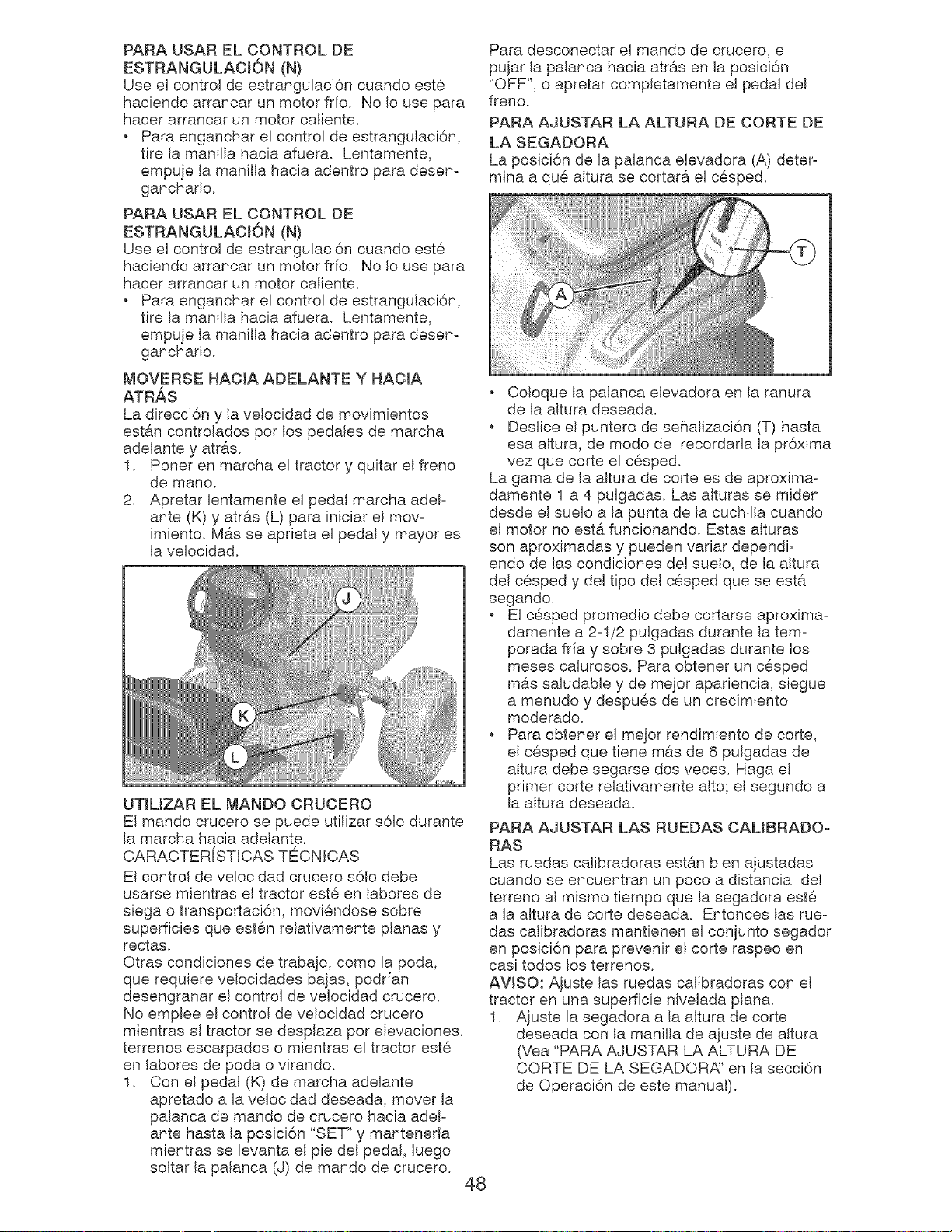
PARA USAR EL CONTROL DE
ESTRANGULACK)N (N)
Use el control de estrangulaci6n cuando este
haciendo arrancar un motor frfo. No Io use para
hacer arrancar un motor caliente.
Para enganchar eI control de estrangulaci6n,
tire la manilla hacia afuera. Lentamente,
empuje la manilla hacia adentro para desen-
gancharlo.
PARA USAR EL CONTROL DE
ESTRANGULACION (N)
Use el control de estrangulaci6n cuando este
haciendo arrancar un motor frio, No Io use para
hacer arrancar un motor caliente.
Para enganchar el control de estrangulaci6n,
tire la manilla hacia afuera. Lentamente,
empuje la manilla hacia adentro para desen-
ganchado.
MOVERSE HACIA ADELANTE Y HACIA
ATRAS
La direcci6n y la velocidad de movimientos
est&n controlados pot los pedales de marcha
adelante y atr&s,
1, Poner en marcha el tractor y quitar el freno
de mano,
2. Apretar lentamente el pedal marcha adel-
ante (K) y atras (L) para iniciar el mov-
imiento. Mas se aprieta el pedal y mayor es
la velocidad.
UTIL[ZAR EL MANDO CRUCERO
El mando crucero se puede utilizar s61o durante
la marcha hacia adelante.
CARACTER[STICAS TECNICAS
El control de velocidad crucero s61o debe
usarse mientras el tractor este en labores de
siega o transportaci6n, moviendose sobre
superficies que esten relativamente planas y
rectas.
Otras condiciones de trabajo, come la poda,
que requiere velocidades bajas, podrfan
desengranar el control de velocidad crucero.
No emplee el control de velocidad crucero
mientras el tractor se desplaza pot elevaciones,
terrenos escarpados o mientras el tractor este
en labores de poda o virando.
1. Con el pedal (K) de marcha adelante
apretado a la velocidad deseada, mover la
palanca de mando de crucero hacia adel-
ante hasta la posici6n "SET" y mantenerla
mientras se levanta el pie del pedal, luego
soltar la palanca (J) de mando de crucero.
48
Para desconectar el mando de crucero, e
pujar la palanca hacia atras en la posici6n
"OFF", o apretar completamente el pedal del
freno.
PARA AJUSTAR LA ALTURA DE OORTE DE
LA SEGADORA
La posici6n de la palanca elevadora (A) deter-
mina a que altura se cortara el cesped.
Coloque la palanca elevadora en la ranura
de la altura deseada.
Deslice el puntero de seSalizaci6n (T) hasta
esa altura, de modo de recordarla la pr6xima
vez que corte el cesped.
La gama de la altura de corte es de aproxima-
damente 1 a 4 pulgadas. Las alturas se miden
desde el suelo a la punta de la cuchilla cuando
el motor no est& funcionando. Estas alturas
son aproximadas y pueden variar dependi-
endo de las condiciones del suelo, de la altura
del cesped y del tipo del cesped que se esta
segando.
. El cesped promedio debe cortarse aproxima-
damente a 2-1/2 pulgadas durante la tem-
porada fria y sobre 3 pulgadas durante los
meses calurosos. Para obtener un cesped
mas saludable y de mejor apariencia, siegue
a menudo y despues de un crecimiento
moderado.
Para obtener el mejor rendimiento de corte,
el cesped que tiene mas de 6 pulgadas de
altura debe segarse dos veces. Haga el
primer corte relativamente alto; el segundo a
la altura deseada.
PARA AJUSTAR LAS RUEDAS CALIBRADO-
RAS
Las ruedas calibradoras estan bien ajustadas
cuando se encuentran un poco a distancia del
terreno al mismo tiempo que la segadora este
a la altura de corte deseada. Entonces las rue-
das calibradoras mantienen el conjunto segador
en posici6n para prevenir el corte raspeo en
casi todos los terrenos.
AVlSO: Aiuste las ruedas calibradoras con el
tractor en una superficie nivelada plana.
1. Ajuste la segadora a la altura de corte
deseada con la manilla de ajuste de altura
(Vea "PARA AJUSTAR LA ALTURA DE
CORTE DE LA SEGADOR,_' en la secci6n
de Operaci6n de este manual).
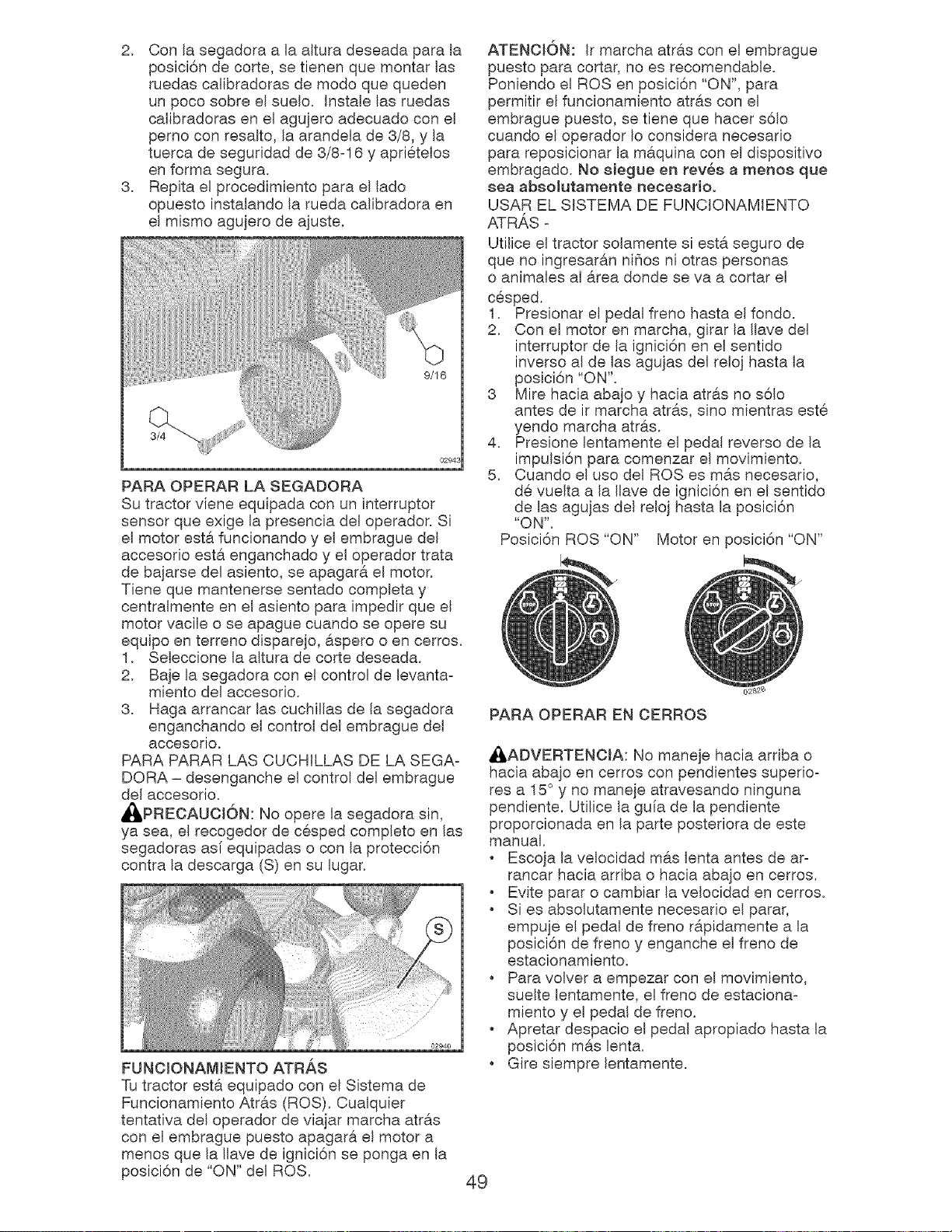
2. Conla segadoraa laalturadeseadaparala
posici6ndecorte,setienenquemontarIns
ruedascalibradorasdemodoquequeden
un pocosobreelsuelo. InstaleInsruedas
calibradorasen el agujeroadecuadoconel
pernoconresalto,la arandelade3/8,y la
tuercadeseguridadde 3/8o16y apri@telos
enformasegura.
3. Repitael procedimientoparael lado
opuestoinstalandola ruedacalibradoraen
el mismoagujerodeajuste.
PARAOPERARLASEGADORA
Sutractorvieneequipadaconuninterruptor
sensorqueexigela presenciadeloperador.Si
el motorest@.funcionandoy elembraguedel
accesorioestaenganchadoy el operadortrata
debajarsedelasiento,seapagarael motor.
Tienequemantenersesentadocompletay
centralmenteenel asientoparaimpedirqueel
motorvacileo seapaguecuandoseoperesu
equipoenterrenodisparejo,asperoo encerros.
1. Seleccionelaalturade cortedeseada.
2. Bajelasegadoraconel controlde levantao
mientodelaccesorio.
3. Hagaarrancarinscuchillasdela segadora
enganchandoel controldelembraguedel
accesorio.
PARAPARARLASCUCHILLASDELASEGAo
DORA- desengancheel controldelembrague
delaccesorio.
_,PRECAUCI6N:Nooperela segadorasin,
yasea,el recogedorde c@spedcompletoenIns
segadorasas[equipadaso conla protecci6n
contraladescarga(S)ensu lugar.
FUNOIONAMIENTOATRAS
Tutractorest&equipadoconel Sistemade
FuncionamientoAtr&s(ROS).Cualquier
tentativadeloperadordeviajarmarchaatr&s
conel embraguepuestoapagar&el motora
menosquela Ilavede ignici6nse pongaenla
posici6nde "ON"delROS.
puestoparacortar,no esrecomendable.
Poniendoel ROSenposici6n"ON",para
permitirelfuncionamientoatr#,sconel
embraguepuesto,setienequehacers61o
cuandoel operadorIoconsideranecesario
parareposicionarla maquinaconel dispositivo
embragado.Nosiegueen rev6sa menosque
seaabsoiutamentenecesario,
USAR EL SISTEMA DE FUNCIONAMIENTO
ATRAS o
Utilice el tractor solamente siesta seguro de
que no ingresaran nihos ni otras personas
o animales al area deride se vaa cortar el
c@sped.
1. Presionar el pedal freno hasta el fondo.
2. Con el motor en marcha, girar la Ilave del
interruptor de la ignici6n en el sentido
inverse al de Ins agujas del relo] hasta la
posici6n "ON".
3 Mire hacia aba]o y hacia atras no s61o
antes de ir marcha atras, sino mientras est@
4. Presione lentamente el pedal reverso de la
impulsi6n para comenzar el movimiento.
5. Cuando el uso del ROS es mas necesario,
d@vuelta a la Ilave de ignici6n en el sentido
de Ins agujas del relo] hasta la posici6n
"ON".
Posici6n ROS "ON" Motor en posici6n "ON"
PARA OPERAR EN OERROS
_ADVERTENCIA: No maneje hacia arriba o
hacia aba]o en cerros con pendientes superioo
res a 15° y no maneje atravesando ninguna
pendiente. Utilice la gufa de la pendiente
proporcionada en la parte posteriora de este
manual.
Escoja la velocidad mas lenta antes de aro
rancar hacia arriba o hacia aba}o en cerros.
Evite parar o cambiar la velocidad en cerros.
Si es absolutamente necesario el parar,
empuje el pedal de freno r@,pidamente a la
posici6n de freno y enganche el freno de
estacionamiento.
Para volver a empezar con el movimiento,
suelte lentamente, el freno de estacionao
miento y el pedal de freno.
Apretar despacio el pedal apropiado hasta la
posici6n mas lenta.
Gire siempre lentamente.
49
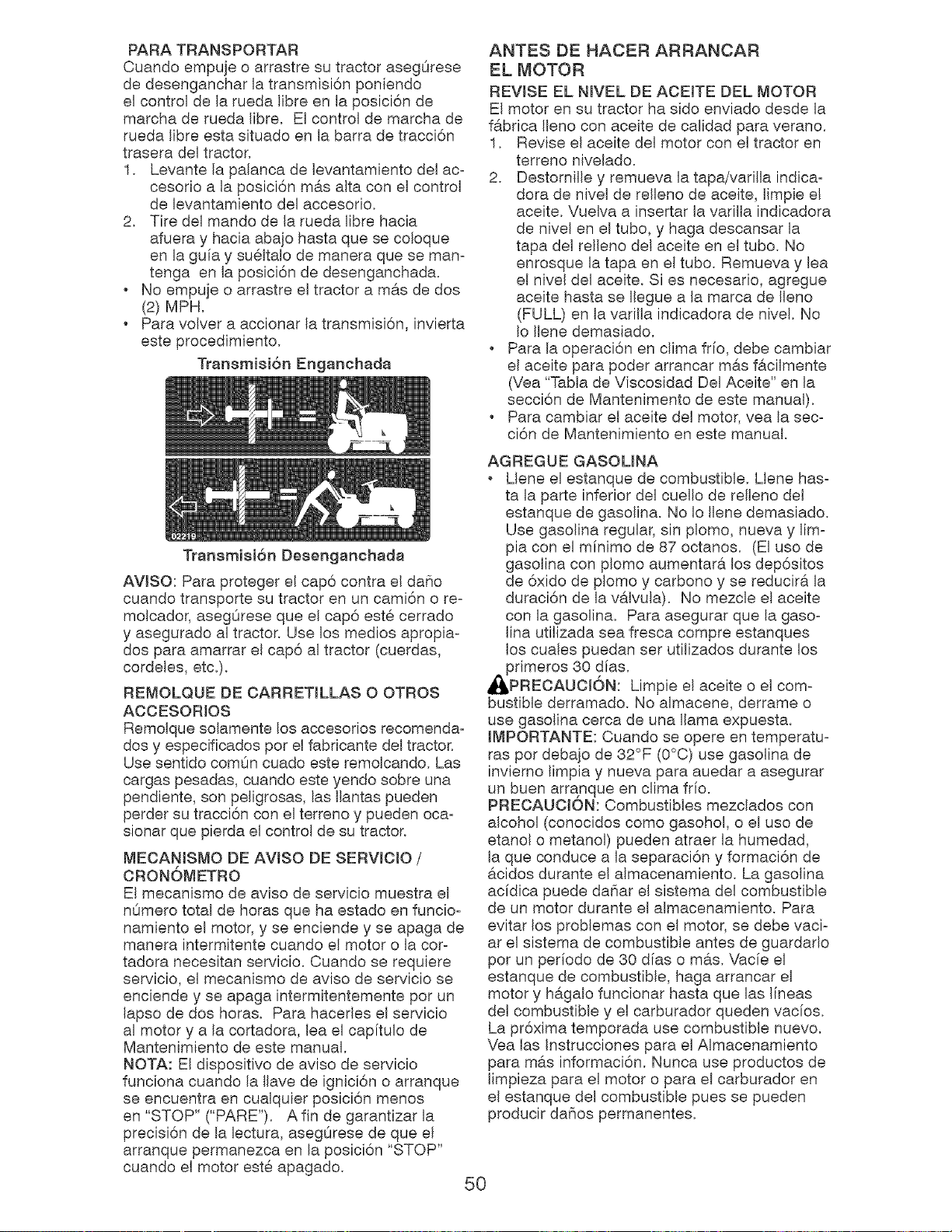
PARA TRANSPORTAR
Cuando empuje o arrastre su tractor asegOrese
de desenganchar la transmisi6n poniendo
el control de la rueda libre en la posici6n de
marcha de rueda fibre. El control de marcha de
rueda Iibre esta situado en la barra de tracci6n
trasera del tractor.
1. Levante la palanca de levantamiento del ac-
cesorio a la posici6n mas alta con el control
de levantamiento del accesorio.
2. Tire del mando de la rueda fibre hacia
afuera y hacia abajo hasta que se coloque
en la guia y su61talo de manera que se man-
tenga en la posici6n de desenganchada.
No empuje o arrastre el tractor a mas de dos
(2) MPH.
Para volver a accionar la transmisi6n, invierta
este procedimiento.
Transmisi6n Enganchada
Transmisi6n Desenganchada
AVlSO: Para proteger el cap6 contra el daSo
cuando transporte su tractor en un cami6n o re-
molcador, asegOrese que el cap6 este cerrado
y asegurado al tractor. Use los medios apropia-
dos para amarrar el cap6 al tractor (cuerdas,
cordeles, etc.).
REMOLQUE DE OARRETILLAS 00TROS
ACCESORIOS
Remolque solamente los accesorios recomenda-
dos y especificados pot el fabricante del tractor.
Use sentido comOn cuado este remolcando. Las
cargas pesadas, cuando este yendo sobre una
pendiente, son peligrosas, las Ilantas pueden
perder su tracci6n con el terreno y pueden oca-
sionar que pierda el control de su tractor.
MECANJSMO DE AVISO DE SERVICIO /
CRONOMETRO
El mecanJsmo de aviso de servicio muestra el
nOmero total de horas que ha estado en funcio-
namiento el motor, y se enciende y se apaga de
manera intermitente cuando el motor o la cor-
tadora necesitan servicio. Cuando se requiere
servicio, el mecanismo de aviso de servicio se
enciende y se apaga intermitentemente par un
lapso de dos horas. Para hacerles el servicio
al motor y a la cortadora, lea el capitulo de
Mantenimiento de este manual.
NOTA: El dispositivo de aviso de servicio
funciona cuando la Ilave de ignici6n o arranque
se encuentra en cualquier posici6n menos
en "STOP" ("PARE"). A fin de garantizar la
precisi6n de la lectura, asegOrese de que el
arranque permanezca en la posici6n "STOP"
cuando el motor este apagado.
ANTES DE HACER ARRANCAR
EL MOTOR
REWSE EL NWEL DE ACEITE DEL MOTOR
El motor en su tractor ha side enviado desde la
fabrica Ileno con aceite de calidad para verano,
1. Revise el aceite del motor con el tractor en
terreno nivelado.
2. Destornille y remueva la tapa/varilla indica-
dora de nivel de relleno de aceite, limpie el
aceite. Vuelva a insertar la varilla indicadora
de nivel en el tubo, y haga descansar la
tapa del relleno del aceite en el tubo. No
enrosque la tapa en el tubo. Remueva y lea
el nivel del aceite. Si es necesario, agregue
aceite hasta se Ilegue a la marca de Ileno
(FULL) en la varilla indicadora de nivel. No
Io Ilene demasiado.
Para la operaci6n en cfima frfo, debe cambiar
el aceite para poder arrancar m#.s facilmente
(Vea "Tabla de Viscosidad Del Aceite" en la
secci6n de Mantenimento de este manual).
Para cambiar el aceite del motor, yea la sec-
ci6n de Mantenimiento en este manual.
AGREGUE GASOLINA
Llene el estanque de combustible. Llene has-
ta la parte inferior del cuello de relleno del
estanque de gasolina. No Io Ilene demasiado.
Use gasolJna regular, sin plomo, nueva y lim-
pia con el mfnimo de 87 octanos. (El uso de
gasolina con plomo aumentar& los dep6sitos
de 6xido de plomo y carbono y se reducir& la
duraci6n de la v&lvula). No mezcle el aceite
con la gasolina. Para asegurar que la gaso-
lina utilizada sea fresca compre estanques
los cuales puedan set utilizados durante los
_primeros 30 dfas.
PREOAUOJ6N: Limpie el aceite o el com-
bustible derramado. No almacene, derrame o
use gasolina cerca de una llama expuesta.
IMPORTANTE: Cuando se opere en temperatu-
ras por debajo de 32°F (0°C) use gasolina de
inviemo limpia y nueva para auedar a asegurar
un buen arranque en clJma frfo.
PREOAUOION: Combustibles mezclados con
alcohol (conocidos como gasohol, o el uso de
etanol o metanol) pueden atraer la humedad,
la que conduce a la separaci6n y formaci6n de
acidos durante el almacenamiento. La gasolina
acidica puede da_iar el sistema del combustible
de un motor durante el almacenamiento. Para
evitar los problemas con el motor, se debe vaci-
ar el sistema de combustible antes de guardado
pot un perfodo de 30 dfas o mas. Vacie el
estanque de combustible, haga arrancar el
motor y h#.galo funcionar hasta que las lineas
del combustible y el carburador queden vacios.
La pr6xima temporada use combustible nuevo.
Vea las Instrucciones para el Almacenamiento
para m#.s informaci6n. Nunca use productos de
limpieza para el motor o para el carburador en
el estanque del combustible pues se pueden
producir daSos permanentes.
50
PARA HACER ARRANCAR EL MOTOR
AI hacer arrancar el motor pot la primera vez o
si se ha acabado el combustible del motor, se
necesitara tiempo para el arranque extra para
mover el combustible desde el estanque hasta
el motor,
1, AsegOrese que el control de rueda libre
este en la posici6n enganchada,
2, Sientase en el sill6n en la posici6n de
operaci6n, suelte el pedal del freno y ponga
el freno de estacionamiento,
3, Mueva el embrague del accesorio a la
posici6n desenganchado disengaged.
4, Mueva el control de la aceleraci6n a la
posici6n de r6.pido,
5, Tire el control de estrangulaci6n a la
posici6n de estrangulaci6n para el arranque
de un motor frio, Para el arrancar un motor
caliente el uso del control de la estrangu-
laci6n puede que no sea necesario,
AVlSO: Antes de arrancar, lea Ins instruccio-
nes siguientes para el arranque en clima frfo y
templado,
6, Inserte la Ilave en la ignici6n y gire la Ilave
en el sentido que giran Ins manillas del reloj
a la posici6n de arranque start, y suelte la
Ilave tan pronto como arranque el motor,
No haga funcionar el arrancador continu-
amente pot mas de quince segundos pot
minuto, Si el motor no arranca despues de
varios intentarlos, mueva el control de la
estrangulaci6n hacia adentro, espere unos
cuantos minutos y trate de nuevo, Si el mo-
tor sigue sin funcionar, estire del control de
la estrangulaci6n y trate de nuevo,
ARRANQUE CON TIEMPO TEMPLADO (50 °
Y MAS)
7, Cuando arranque el motor, empuje el con-
trol de la estrangulaci6n hasta que el motor
empiece a funcionar m#,s suavemente, Si
el motor empieza a funcionar mal, estire
del control de la estrangulaci6n un poco
pot unos cuantos segundos y entonces
continue a empujar lentamente el control,
, Los accesorios y el embrague de suelo
ahora puede ser utilizados, Si el motor no
acepta esta carga, vuelva a arrancar el motor
para permitirle que se caliente pot un minuto,
utilizando el estrangulador como describido
arriba,
ARRANQUE CON TIEMPO FR[O (50° Y
MENOS)
7, Cuando arranque el motor, empuje lenta-
mente el control de la estrangulaci6n hacia
adentro hasta que el motor empiece a
funcionar suavemente, Sign empujandolo
poco a poco permitiendo que el motor acepte
peque_os cambios de velocidad y carga,
hasta que este completamente hacia aden-
tro, Si el motor empieza a funcionar mal, es-
tire del control de la estrangulaci6n un poco
por unos cuantos segundos y continOe a
empujar el control hacia adentro, Esto puede
requerir que el motor se caliente pot unos
cuantos minutos, depende de la temperatura,
CALENTAMENTO PARA LA TRANSMISION
AUTOMATICA
Antes de conducir la unidad en un tiempo iffo,
la transmisi6n debe set calentada como Ins
instrucciones siguientes:
1, AsegOrese que el tractor este situado en
una superficie nivelada,
2, Alivie el freno de estacionamiento y deje
que el freno vuelva a la posici6n de opero
aci6n,
3, Permita que la transmisi6n se caliente
durante un minuto, Esto puede set echo du=
rante el tiempo de calentamiento del motor.
Los accesorios pueden set utilizados durante
el periodo del recalentamiento del mo-
tor despues que la transmisi6n halla sido
calentada y puede requerir que el control de
la estrangulaci6n sea estirado un poco,
AVlSO: Si se encuentra a mucha altura (sobre
3000 pies) o en clima frio (pot debajo de 32°F
[0°C]), la mezcla del combustible del carburador
debe set ajustada para el mejor rendimiento
del motor, (Vea "PARA AJUSTAR EL CARBU-
RADOR" en la secci6n de Servicio y Ajustes de
este manual),
RGAR LA TRANSMISI(DN
PRECAUCION: Nunca enganche o desen-
ganche la palanca del control de rueda libre
cuando el motor esta funcionando,
Para asegurar la operaci6n y ejecuci6n adec-
uada, es recomendado que la transmisi6n sea
purgada antes de operar el tractor para la prim-
era vez, Este proceso removera cualquier aire
adentro de la transmisi6n que se halla formado
durante el transporte de su tractor,
IMPORTANTE: Si pot acaso su transmisi6n
debe set removida para servicio o reemplazo,
debe set purgada despues de la reinstalaci6n y
antes de operar el tractor,
1, Para mayor seguridad, ubique el tractor
en una superficie nivelada, despejada de
cualquier objeto y abierta, con el motor
apagado y el freno de mano puesto,
2, Desenganche la transmisi6n poniendo el
control de rueda libre en la posici6n de
desenganchado (Vea "PARA EL TRANS-
PORTE" en esta secci6n de este manual),
51
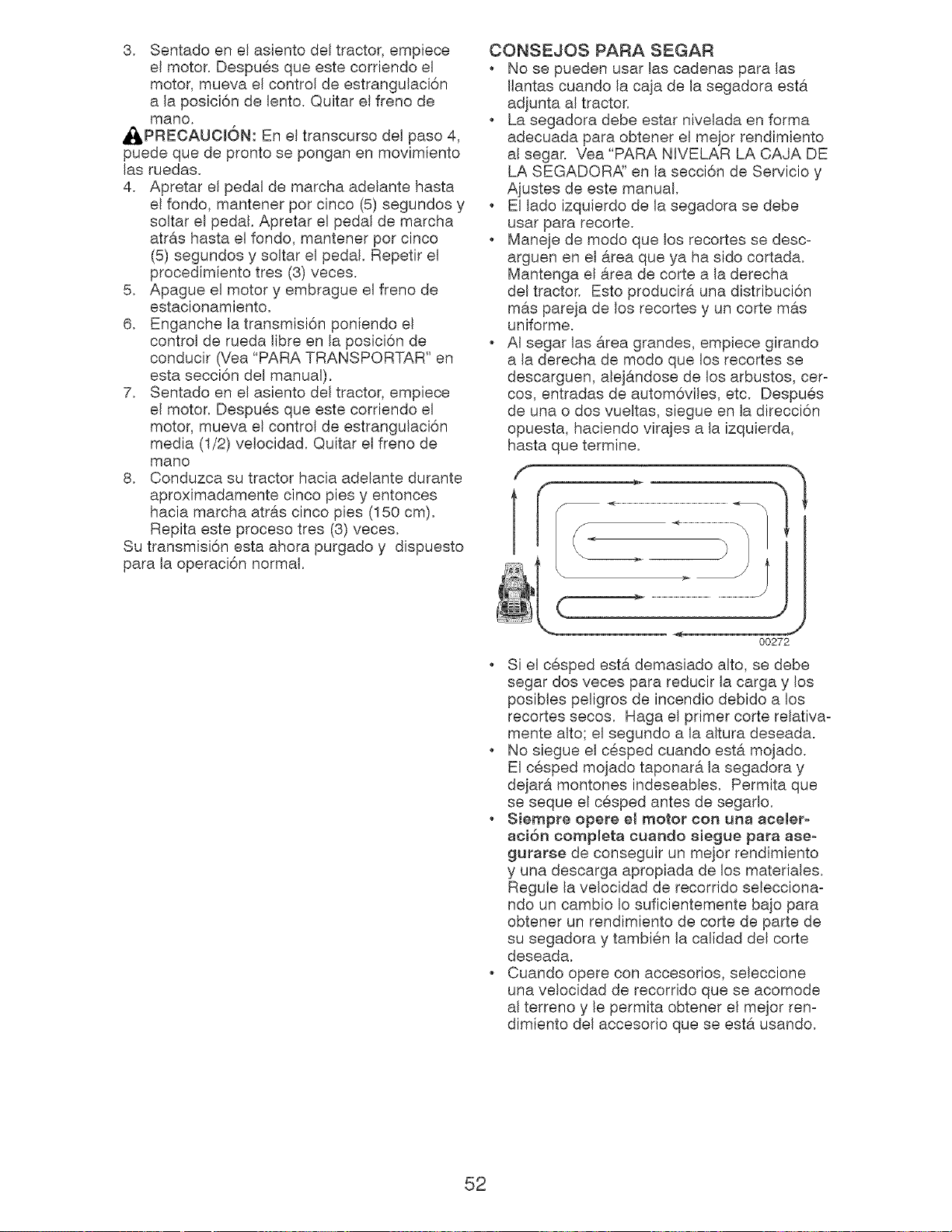
3. Sentado en el asiento del tractor, empiece
el motor. Despu@s que este corriendo el
motor, mueva el control de estrangulaci6n
a la posici6n de lento. Quitar el freno de
mane,
Ai:_PRECAUCI6N: En el transcurso del paso 4,
puede que de pronto se pongan en movimiento
las ruedas.
4. Apretar el pedal de marcha adelante hasta
el fondo, mantener pot cinco (5) segundos y
soltar el pedal. Apretar el pedal de marcha
(5) segundos y soltar el pedal. Repetir el
procedimiento tres (3) veces.
5. Apague el motor y embrague el freno de
estacionamiento.
6. Enganche la transmisi6n poniendo el
control de rueda libre en la posici6n de
conducir (Vea "PARA TRANSPORTAR" en
esta secci6n del manual).
7. Sentado en el asiento del tractor, empiece
el motor. Despu@s que este corriendo el
motor, mueva el control de estrangulaci6n
media (1/2) velocidad. Quitar el freno de
mano
8. Conduzca su tractor hacia adelante durante
aproximadamente cinco pies y entonces
hacia marcha atras cinco pies (150 cm).
Repita este proceso tres (3) veces.
Su transmisi6n esta ahora purgado y dispuesto
para la operaci6n normal.
CONSEJOS PARA SEGAR
No se pueden usar las cadenas para las
Ilantas cuando la caja de la segadora esta
adjunta al tractor.
La segadora debe estar nivelada en forma
adecuada para obtener el mejor rendimiento
al segar. Vea "PARA NIVELAR LA CAJA DE
LA SEGADOR,_' en la secci6n de Servicio y
Ajustes de este manual.
El lado izquierdo de la segadora se debe
usar para recorte.
Maneje de modo que los recortes se desco
arguen en el area que ya ha sido cortada.
Mantenga el area de corte a la derecha
del tractor. Esto producira una distribuci6n
mas pareja de los recortes y un corte mas
uniforme.
AI segar las area grandes, empiece girando
a la derecha de modo que los recortes se
descarguen, ale]andose de los arbustos, cero
cos, entradas de autom6viles, etc. Despu@s
de una o dos vueltas, siegue en la direcci6n
opuesta, haciendo virajes a la izquierda,
hasta que termine.
f
f
00272
. Si el c@sped est6, demasiado alto, se debe
segar dos veces para reducir la carga y los
posibles peligros de incendio debido a los
recortes secos. Haga el primer corte relativao
mente alto; el segundo a la altura deseada.
. No siegue el c@sped cuando esta mojado.
El c@sped mojado taponara la segadora y
dejara montones indeseables. Permita que
se seque el c@sped antes de segado.
. Siempre opere el motor con una aceIer-
aci6n completa cuando 8[egue para aee-
guraree de conseguir un mejor rendimiento
y una descarga apropiada de los materiales.
Regule la velocidad de recorrido seleccionao
ndo un cambio Io suficientemente ba]o para
obtener un rendimiento de corte de parte de
su segadora y tambi@n la calidad del carte
deseada.
. Cuando opere con accesorios, seleccione
una velocidad de recorrido que se acomode
al terreno y le permka obtener el mejor reno
dimiento del accesorio que se esta usando.
52
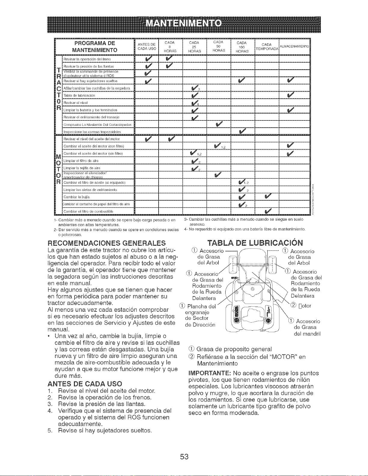
P'RoGRAMA DE ANTES DE CADA
MANTENIM|ENTO CADA USO 8
HORAS
m
Revisar la operacid_n del freno _
RevJsar la presi6n de las Ilantas _
T V_rifiez la cornrnande de pr6sence
R d'op6rateur et le sistema d ROS
A Rewisar si hay sujetadores sueltos
C Afilar/cambiar las cuchillas de la segadora
T labia de lubricaci6n
0 Revisar el rdvel
H Limpiar la bateria y los terminales
Revisar el enfriarniento del transeie
Compluebe La Nivelaci6n Del Cortacespedes
Insl)eccione las correas trapezoidales
E
Revisar el nivel del aceite del rnotor _
Carnbiar el aceite del motor (con filtro)
CarnMar el aceite del motor (sin flltro)
_ Limpiar el flltro de aire
TO Limpiar la rejilla de aire
Inspeccionar el silenciador/
amortiGuador de chispas
CarnMar el filtro de aceite (si equipado)
Limpiar las aletas de enfriamiento
Cambiar la buj[a
;ambiar el cartucho de papel del filtro de air÷
Cambiar el filtro de combustible
1- Cambiar m_ts a menudo cuando se opere bajo carga pesada o en
ambientes con altas temperaturas,
2- Bar serv[o[o m_s a menudo cuando se opere en cond[c[ones suc[as
o polvorosas.
RECOMENDACIONES GENERALES
La garantfa de este tractor no cubre los art[cu-
los que hart estado sujetos al abuse o a la neg°
ligencia del operador. Para recibir todo el valor
de la garant[a, el operador tiene que mantener
la segadora segOn las instrucciones descritas
en este manual.
Hay algunos ajustes que se tienen que hacer
en forma peri6dica para poder mantener su
tractor adecuadamente.
AI menos una vez cada estaci6n comprobar
si es necesario efectuar los adjustes descritos
en las secciones de Servicio y Ajustes de este
manual.
, Una vez al abe, cambie la bujia, Iimpie o
cambie el filtro de aire y revise si las cuchillas
y las correas estan desgastadas. Una bujia
nueva y un filtro de aire limpio aseguran una
mezcla de aire-combustible adecuada y le
ayudan a que su motor funcione mejor y que
dure mas.
ANTES DE CADA USO
1. Revise el nivel del aceite del motor.
2. Revise la operaci6n de los frenos.
3. Revise la presi6n de las Ilantas.
4. Verifique que el sistema de presencia del
operado y el sistema del ROS funcionen
adecuatamente.
5. Revise si hay sujetadores sueltos.
CADA CADA CADA CADA ALMACENAMIENTO
25 50 100 rEMPORADA
HORAS HORAS HORAS
t/ i/
i
_,2
t/2
3- Cambiar las cuchillas mas a menudo cuando se siegue en suelo
arenoso.
4- No requerido si equipado con una bateria libre de mantenimiento.
TAIBLA DE LUBRICACION
_!_ -- _!_Accesorio
de Grasa de Grasa
del Arbo! del Arbol
_!_ Accesorio
de Grasa de! de Grasa del
Rodamiento Rodamiento
de la Rueda de la Rueda
Delantera Delantera
_!_ Plancha del "(:}) Doter
engranaje
de Sector ) Accesorio
de Direcci6n de Grasa
de! mandril
_!-_Grasa de proposito general
@ Refierase a la secci6n del "MOTOR" en
Mantenimiento
IMPORTANTE: No aceite o engrase los puntos
pivotes, los que tienen rodamientos de nil6n
especiales. Los lubricantes viscosos atraer&n
polvo y mugre, Io que acortara la duraci6n de
los rodamientos. Si cree que lubricarse, use
solamente un lubricante tipo grafito de polvo
seco en forma moderada.
53
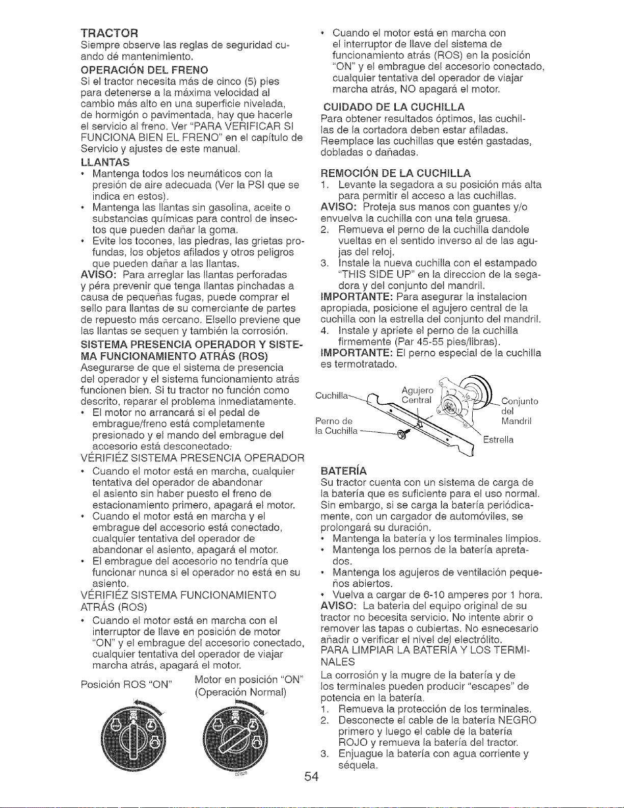
TRACTOR
Siempre observe las reglas de seguridad cu-
ando d@mantenimiento.
OPERACI6N DEL FRENO
Si el tractor necesita m&s de cinco (5) pies
para detenerse a la m&xima velocidad al
cambio mas alto en una superficie nivelada,
de hormig6n o pavimentada, hay que hacerle
el servicio al freno. Vet "PARA VERIFICAR SI
FUNCIONA BIEN EL FRENO" en el capitulo de
Servicio y ajustes de este manual.
LLANTAS
Mantenga todos los neumaticos con la
presi6n de aire adecuada (Vet la PSI que se
indica en estos).
Mantenga las Ilantas sin gasolina, aceite o
substancias quimicas para control de insec-
tos que pueden da_ar la goma.
Evite los tocones, las piedras, las grietas pro-
fundas, los objetos afilados y otros peligros
que pueden dafiar alas Ilantas.
AV[SO: Para arreglar las Ilantas perforadas
y p@ra prevenir que tenga Ilantas pinchadas a
causa de peque_as fugas, puede comprar el
sello para Ilantas de su comerciante de partes
de repuesto m6.s cercano. EIsello previene que
las Ilantas se sequen y tambi@n la corrosi6n.
SlSTEMA PRESENOJA OPERADOR Y SlSTE-
MA FUNC[ONAMIENTO ATRAS (ROS)
Asegurarse de que el sistema de presencia
del operador y el sistema funcionamiento atr&s
funcionen bien. Si tu tractor no funci6n como
descrito, reparar el problema inmediatamente.
El motor no arrancara si el pedal de
embrague/freno esta completamente
presionado y el mando del embrague del
accesorio est,. desconectado:
VERIFIEZ SISTEMA PRESENCIA OPERADOR
Cuando el motor esta en marcha, cualquier
tentativa del operador de abandonar
el asiento sin haber puesto el freno de
estacionamiento primero, apagara el motor.
Cuando el motor esta en marcha y el
embrague del accesorio est6, conectado,
cualquier tentativa del operador de
abandonar el asiento, apagar6, el motor.
El embrague del accesorio no tendria que
funcionar nunca si el operador no est,. en su
asiento.
VERIFIE'_Z SISTEMA FUNCIONAMIENTO
ATRAS (ROS)
Cuando el motor esta en marcha con el
interruptor de Ilave en posici6n de motor
"ON" y el embrague del accesorio conectado,
cualquier tentativa del operador de viajar
marcha atras, apagara el motor.
Posici6n ROS "ON" Motor en posici6n "ON"
(Operaci6n Normal)
3,
54
Cuando el motor est#. en marcha con
el interruptor de Ilave del sistema de
funcionamiento atr6.s (ROS) en la posici6n
"ON" y el embrague del accesorio conectado,
cualquier tentativa del operador de viajar
marcha atr6.s, NO apagar6, el motor.
CUIDADO DE LA CUCHILLA
Para obtener resultados 6ptimos, las cuchil-
las de la cortadora deben estar afiladas.
Reemplace las cuchillas que est@n gastadas,
dobladas o da5adas.
REMOCION DE LA CUCHLLA
1. Levante la segadora a su posici6n mas alta
para permitir el acceso alas cucMWas.
AWSO: Proteja sus manes con guantes y/o
envuelva la cuchilla con una tela gruesa.
2. Remueva el perno de la cuchilla dandole
vueltas en el sentido inverso al de las agu-
]as del relo].
3. Instale la nueva cuchilla con el estampado
"THIS SIDE UP" en la direccion de la sega-
dora y del conjunto del mandril.
IMPORTANTE: Para asegurar la instalacion
apropiada, posicione el agujero central de la
cuchilla con la estrella del conjunto del mandril.
4. Instale y apriete el perno de la cuchilla
firmemente (Par 45-55 pies/libras).
IMPORTANTE: El perno especial de la cuchilla
es termotratado.
Agujero
Centra!
Perno de
la Cuchi!la ...........
Jnto
del
Mandril
Estre!la
BATERiA
Su tractor cuenta con un sistema de carga de
la bateria que es suficiente para el uso normal.
Sin embargo, si se carga la baterfa peri6dica-
mente, con un cargador de autom6viles, se
prolongara su duraci6n.
Mantenga la bateria y los terminales limpios.
Mantenga los pernos de la bateria apreta-
dos.
Mantenga los agujeros de ventilaci6n peque-
flos abiertos.
Vuelva a cargar de 6-10 amperes pot 1 hora.
AWSO: La bateria del equipo original de su
tractor no becesita servicio. No intente abrir o
remover las tapas o cubiertas. No esnecesario
afiadir o verificar el nivel del electr61ito.
PARA LIMPIAR LA BATERIA Y LOS TERMI-
NALES
La corrosi6n y la mugre de la bateria y de
los terminales pueden producir "escapes" de
potencia en la baterfa.
1. Remueva la protecci6n de los terminales.
2. Desconecte el cable de la bateria NEGRO
primero y luego el cable de la bateria
ROJO y remueva la baterfa del tractor.
Enjuague la bater[a con agua corriente y
s@quela.
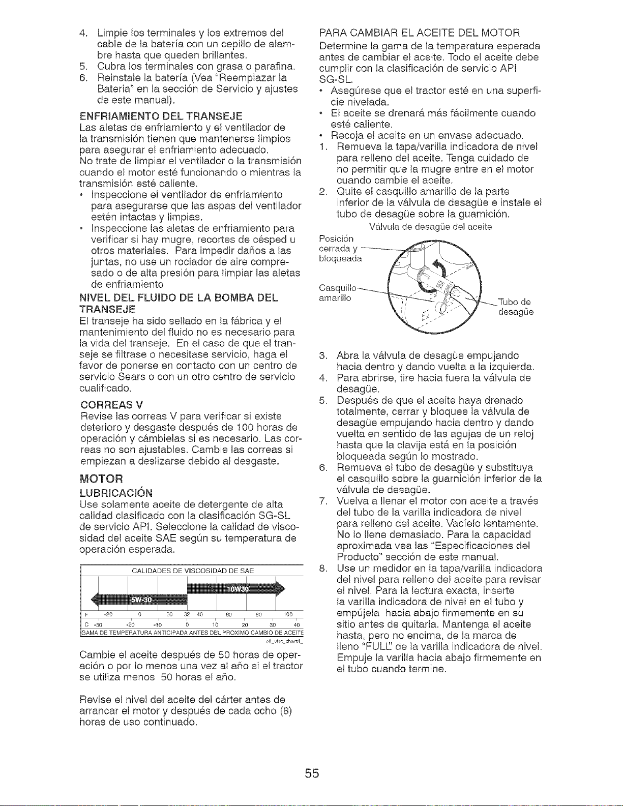
4. Limpielosterminalesy los extremosdel
cablede la bateriaconuncepillode alam-
brehastaquequedenbrillantes.
5. Cubralosterminalescongrasao parafina.
6. Reinstalela baterfa(Vea"Reemplazarla
Bateria"en lasecci6nde Servicioy ajustes
de estemanual).
ENFRIAMIENTODELTRANSEJE
Lasabtas deenfriamientoy elventiladorde
latransmisi6ntienenquemantenerselimpios
paraasegurarel enfriamientoadecuado.
Notratede limpiarelventiladorola transmisi6n
cuandoel motorest@funcionandoo mientrasla
transmisi6nest@caliente.
Inspeccioneelventiladorde enfriamiento
paraasegurarsequelasaspasdelventilador
est@nintactasy limpias.
Inspeccionelasaletasde enfriamientopara
verificarsi haymugre,recortesdec@spedu
otrosmateriales.Paraimpedirdafiosalas
juntas,nouseunrociadorde airecompre°
sadoo dealtapresi6nparalimpiarlasabtas
de enfriamiento
NIVELDELFLUIDODELA BOMBADEL
TRANSEJE
Eltransejehasidoselladoen lafabricay el
mantenimientodelfluidonoesnecesariopara
lavidadeltranseje.Enel casodequeel tram
sejesefiltraseo necesitaseservicio,hagael
favorde ponerseen contactoconuncentrode
servicioSearsoconunottocentrode servicio
cualificado.
OORREASV
ReviselascorreasV paraverificarsi existe
deterioroy desgastedespu@sde 100horasde
operaci6ny cambielassi es necesario.Lascot°
teasnosonajustables.Cambielascorreassi
empiezanadeslizarsedebidoal desgaste.
MOTOR
LUBRICACI6N
Usesolamenteaceitededetergentedealta
calidadclasificadoconla clasificaci6nSG-SL
deservicioAPI,Seleccionela calidaddevisco°
sidaddelaceiteSAEsegOnsutemperaturade
operaci6nesperada.
CALIDADES DE VISCOSIDAD DE SAE
oil vise chart4
Cambie el aceite despu@s de 50 horas de oper°
aci6n o pot Io menos una vez al a_io si el tractor
se utiliza menos 50 horas el aSo.
Revise el nivel del aceite del c#.rter antes de
arrancar el motor y despu@s de cada ocho (8)
horas de uso continuado.
PARA CAMBIAR EL ACEITE DEL MOTOR
Determine la gama de la temperatura esperada
antes de cambiar el aceite. Todo el aceite debe
cumplir con la clasificaci6n de servicio API
SG-SL
AsegOrese que el tractor est@en una superfb
cie nivelada.
est@caliente.
Recoja el aceite en un envase adecuado.
1. Remueva la tapa/varilla indicadora de nivel
para relleno del aceite. Tenga cuidado de
no permitir que la mugre entre en el motor
cuando cambie el aceite.
2. Quite el casquillo amarillo de la parte
inferior de la valvula de desagOe e instale el
tuba de desagOe sobre la guarnici6n.
V&lvula de desagOedel aceite
Posbi6n
3. Abra la v@,lvulade desagOe empujando
hacia dentro y dando vuelta a la izqubrda.
4. Para abrirse, tire hacia fuera la valvula de
desagOe.
5. Despu@s de que el aceite haya drenado
totalmente, cerrar y bloquee la valvula de
desagOe empujando hacia dentro y dando
vuelta en sentido de las agujas de un relo]
hasta que la clavija esta en la posici6n
bloqueada segOn Io mostrado.
6. Remueva el tube de desagOe y substituya
el casquillo sobre la guarnici6n inferior de la
v#,lvula de desagOe.
7. Vuelva a Ilenar el motor con aceite a trav@s
del tubo de la varilla indicadora de nivel
para relleno del aceite. Vac[elo lentamente.
No Io Ilene demasiado. Para la capacidad
aproximada vea las "Especificaciones del
Producto" secci6n de este manual.
8. Use un medidor en la tapa/varilla indicadora
del nivel para relleno del aceite para revisar
el nivel. Para la lectura exacta, inserte
la varilla indicadora de nivel en el tubo y
empOjela hacia abajo firmemente en su
sitio antes de quitarla. Mantenga el aceite
hasta, pete no encima, de la marca de
Ileno "FULL' de la varilla indicadora de nivel.
Empuje la varilla hacia abajo firmemente en
el tuba cuando termine.
55
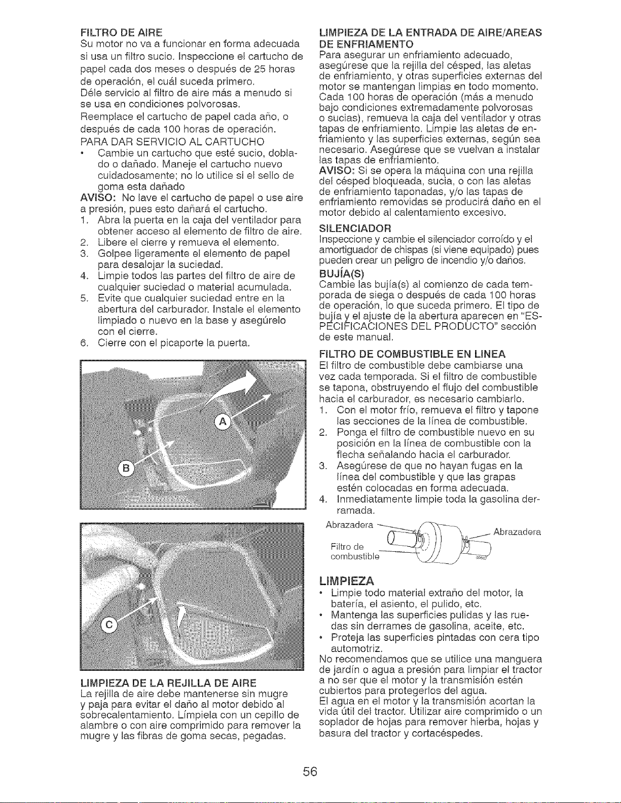
FILTRO DE AIRE
Su motor no va a funcionar en forma adecuada
si usa un filtro sucio, Inspeccione el cartucho de
papel cada dos meses o despues de 25 horas
de operaci6n, el cu&l suceda primero.
Dele servicio al filtro de aire mas a menudo si
se usa en condiciones polvorosas,
Reemplace el cartucho de papel cada aho, o
despues de cada 100 horas de operaci6n,
PARA DAR SERVICIO AL CARTUCHO
Cambie un cartucho que este sucio, dobla-
do o dahado, Maneje el cartucho nuevo
cuidadosamente; no Io utilice si el sello de
goma esta daCiado
AVlSO: No lave el cartucho de papel o use aire
a presi6n, pues esto dafiara el cartucho.
1, Abra la puerta en la caja del ventilador para
obtener acceso al elemento de filtro de aire,
2, Libere el cierre y remueva el elemento,
3, Golpee ligeramente el elemento de papel
para desalojar la suciedad,
4, Limpie todos las partes del filtro de aire de
cualquier suciedad o material acumulada,
5, Evite que cualquier suciedad entre en la
abertura del carburador, Instale el elemento
limpiado o nuevo en la base y asegOrelo
con el cierre,
6, Cierre con el picaporte la puerta,
LIMPIEZA DE LA REJILLA DE AIRE
La rejilla de aire debe mantenerse sin mugre
y paja para evitar el da5o al motor debido al
sobrecalentamiento, Limpiela con un cepillo de
alambre o con aire comprimido para remover la
mugre y las fibras de goma secas, pegadas,
LiMPIEZA DE LA ENTRADA DE AIRE/AREAS
DE ENFRIAMENTO
Para asegurar un enfriamiento adecuado,
asegOrese que la rejilla del cesped, las aletas
de enfriamiento, y otras superficies externas del
motor se mantengan limpias en todo memento.
Cada 100 horas de operaci6n (m&s a menudo
bajo condiciones extremadamente polvorosas
o sucias), remueva la caja del ventilador y otras
tapas de enfriamiento, Limpie las aletas de en-
friamiento y las superficies externas, segOn sea
necesario, AsegOrese que se vuelvan a instalar
las tapas de enfriamiento,
AWSO: Si se opera la m&quina con una rejilla
del cesped bloqueada, sucia, o con las aletas
de enfriamiento taponadas, y/o las tapas de
enfriamiento removidas se producir& da5o en el
motor debido al calentamiento excesivo,
SJLENCIADOR
Inspeccione y cambie el silenciador corroido y el
amortiguador de chispas (si viene equipado) pues
pueden crear un peligro de incendio y/o daSos,
BUJiA(S)
Cambie las bujia(s) al comienzo de cada tem-
porada de siega o despues de cada 100 horas
de operaci6n, Io que suceda primero, El tipo de
bujia y el ajuste de la abertura aparecen en "ES-
PECIFICACIONES DEL PRODUCTO" secci6n
de este manual,
FILTRO DE COMBUSTIBLE EN MNEA
El filtro de combustible debe cambiarse una
vez cada temporada, Si el filtro de combustible
se tapona, obstruyendo el flujo del combustible
hacia el carburador, es necesario cambiado,
1, Con el motor frfo, remueva el filtro y tapone
las secciones de la linea de combustible,
2, Ponga el filtro de combustible nuevo en su
posici6n en la linea de combustible con la
flecha sefialando hacia el carburador,
3, AsegOrese de que no hayan fugas en la
linea del combustible y que las grapas
esten colocadas en forma adecuada.
Inmediatamente limpie toda la gasolina der-
ramada,
4,
Abrazadera
Filtro de
combustible
Abrazadera
LmMPIEZA
Limpie todo material extraSo del motor, la
bateria, el asiento, el pulido, etc,
Mantenga las superficies pulidas y las rue-
das sin derrames de gasolina, aceite, etc,
, Proteja las superficies pintadas con cera tipo
automotriz,
No recomendamos que se utilice una manguera
de jardin o agua a presi6n para limpiar el tractor
a no set que el motor y la transmisi6n esten
cubiertos para protegedos del agua,
El agua en el motor y la transmisi6n acortan la
vida Otil del tractor, Utilizar aire comprimido oun
soplador de hojas para remover hierba, hojas y
basura del tractor y cortacespedes,
56
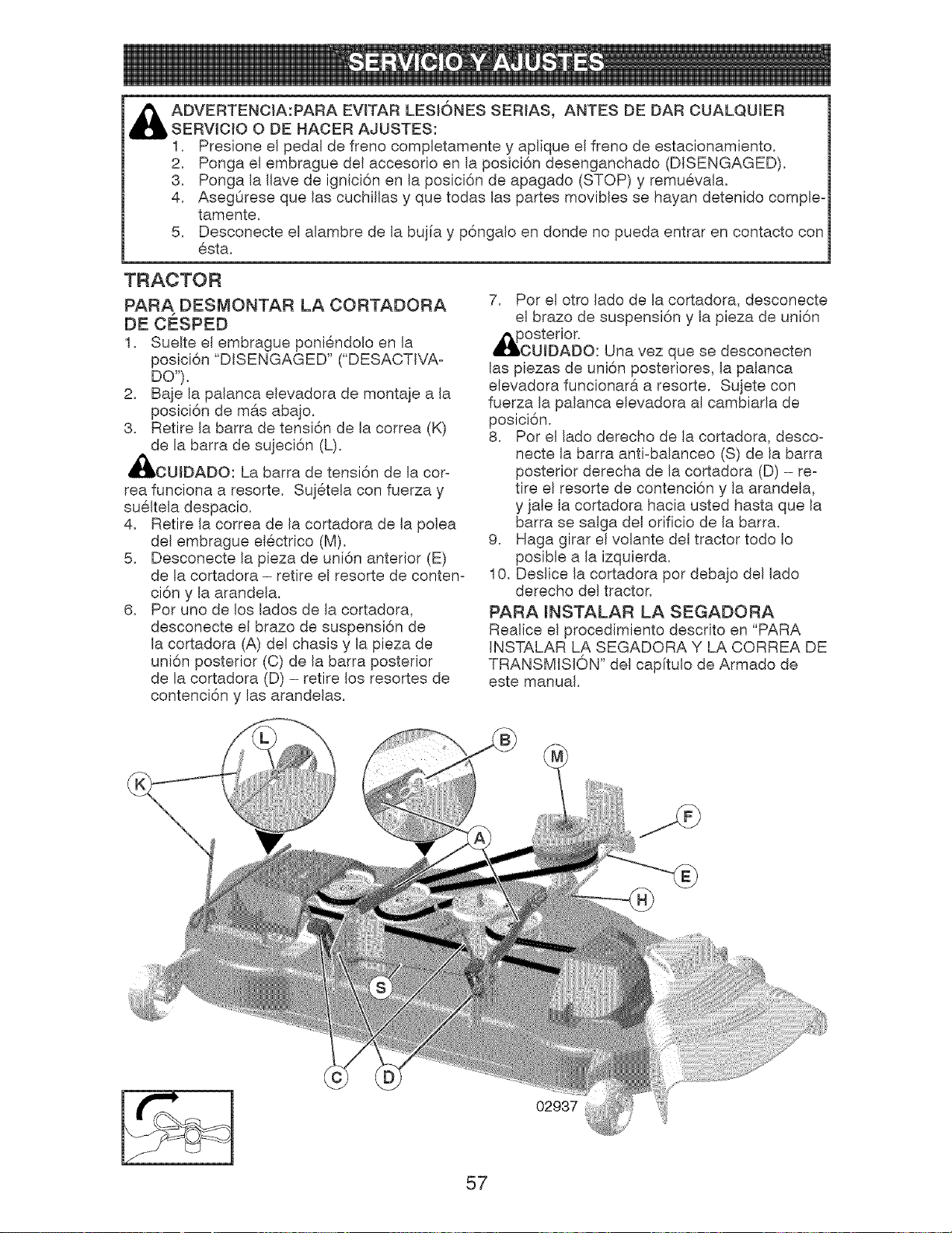
ADVERTENCIA:PARA EVITAR LESJ6NES SERIAS, ANTES DE DAR CUALQUIER
SERVICIO O DE HACER AJUSTES:
1, Presione el pedal de freno completamente y aplique el freno de estacionamiento,
2, Ponga el embrague del accesorio en la posici6n desenganchado (DISENGAGED),
3, Ponga la Ilave de ignici6n en la posici6n de apagado (STOP) y remuevala,
4, AsegOrese que las cuchillas y que todas las partes movibles se hayan detenido comple-
tamente,
5, Desconecte el alambre de la bujia y p6ngalo en donde no pueda entrar en contacto con
esta,
TRACTOR
PARA DESMONTAR LA CORTADORA
DE CESPED
1, Suelte el embrague poniendolo en la
posici6n "DISENGAGED" ("DESACTWA-
DO"),
2, Baje la palanca elevadora de montaje a la
posici6n de m#.s abajo,
3, Retire la barra de tensi6n de la correa (K)
de la barra de sujeci6n (L),
_IbOUIDADO: La barra de tensi6n de la cot-
tea funciona a resorte, Sujetela con fuerza y
sueltela despacio,
4, Retire la correa de la cortadora de la polea
del embrague electrico (M),
5, Desconecte la pieza de uni6n anterior (E)
de la cortadora - retire el resorte de conten-
ci6n y la arandela,
6, Pot uno de los lados de la cortadora,
desconecte el brazo de suspensi6n de
la cortadora (A) del chasis y la pieza de
uni6n posterior (C) de la barra posterior
de la cortadora (D) - retire los resortes de
contenci6n y las arandelas,
7, Pot el otto lado de la cortadora, desconecte
el brazo de suspensi6n y la pieza de uni6n
_IPOosterior,
UIDADO: Una vez que se desconecten
las piezas de uni6n posteriores, la palanca
elevadora funcionara a resorte, Sujete con
fuerza la palanca elevadora al cambiada de
posici6n,
8, Pot el lado derecho de la cortadora, desco-
necte la barra anti-balanceo (S) de la barra
posterior derecha de la cortadora (D) - re-
tire el resorte de contenci6n y la arandela,
y jale la cortadora hacia usted hasta que la
barra se salga del orificio de la barra,
9, Haga girar el volante del tractor todo Io
posible a la izquierda,
10, Deslice la cortadora pot debajo del lado
derecho del tractor,
PARA mNSTALAR LA SEGADORA
Realice el procedimiento descrito en "PARA
INSTALAR LA SEGADORA Y LA CORREA DE
TRANSMISION" del capitulo de Armado de
este manual,
57
02937
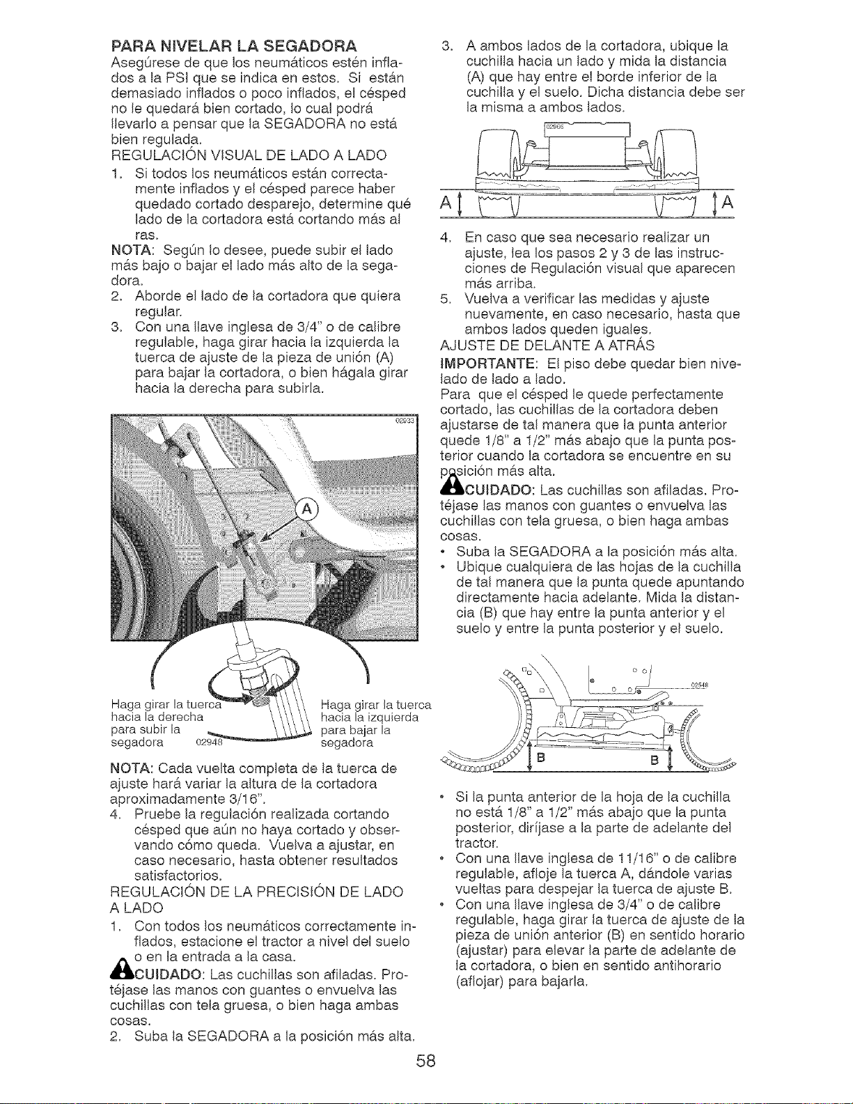
PARA NJVELARLA SEGADORA 3.
AsegQresedequelosneumiticosesteninfla-
dosa la PSIqueseindicaenestos. Si estin
demasiadoinfladoso pocoinflados,el cesped
nole quedaribiencortado,Iocualpodri
Ilevadoa pensarquela SEGADORAnoesti
bienregulada.
REGULACIONVISUALDELADOA LADO
1. Sitodoslosneumiticosestin correcta-
menteinfladosy el cespedparecehaber
quedadocortadodesparejo,determineque A
lado de la cortadora esti cortando mis al
ras. 4.
NOTA: SegOn Io desee, puede subir el lado
mis bajo o bajar el lado mis alto de la sega-
dora.
2. Aborde el lado de la cortadora que quiera
regular.
3. Con una Ilave inglesa de 3/4" o de calibre
regulable, haga girar hacia la izquierda la
tuerca de ajuste de la pieza de uni6n (A)
para bajar la cortadora, o bien higala girar
hacia la derecha para subirla.
-- 02933
!
A ambos lados de la cortadora, ubique la
cuchilla hacia un lado y mida la distancia
(A) que hay entre el borde inferior de la
cuchilla y el suelo. Dicha distancia debe ser
la misma a ambos lados.
En oaso que sea neoesario realizar un
ajuste, lea los pasos 2 y 3 de las instruc-
clones de Regulaci6n visual que aparecen
mis arriba.
5. Vuelva a verificar las medidas y ajuste
nuevamente, en caso necesario, hasta que
ambos lados queden iguales.
AJUSTE DE DELANTE A ATRAS
IMPORTANTE: El piso debe quedar bien nive-
lado de lado a lado.
Para que el cesped le quede perfectamente
cortado, las cuchillas de la cortadora deben
ajustarse de tal manera que la punta anterior
quede 1/8" a 1/2" mis abajo que la punta pos-
terior cuando la cortadora se encuentre en su
icidn mils aJta.
OUiDADO: Las cuchiilas son afiladas. Pro-
tejase las manos con guantes o envuelva las
cuchillas con tela gruesa, o bien haga ambas
oosas.
o Suba la SEGADORA a la posici6n mis alta.
Ubique cualquiera de las hojas de la cuchilia
de tal manera que la punta quede apuntando
directamente hacia adelante. Mida la distan-
cia (B) que hay entre la punta anterior y el
suelo y entre la punta posterior y el suelo.
Haga girar la Haga girar la tuerca
hacia la derecha hacia la izquierda
para subir la para bajar la
segadora 02948 segadora
NOTA: Cada vuelta completa de la tuerca de
ajuste hari variar la altura de la cortadora
aproximadamente 3/16".
4. Pruebe la regulaci6n realizada cortando
cesped que aOn no haya cortado y obser-
vando c6mo queda. Vuelva a ajustar, en
caso necesario, hasta obtener resultados
satisfactorios.
REGULACION DE LA PRECISION DE LADO
A LADO
1. Con todos los neumiticos correctamente in-
flados, estacione el tractor a nivel del suelo
Ao en la entrada a la casa.
OUIDADO: Las cuchillas son afiladas. Pro-
tejase las manos con guantes o envuelva las
cuchillas con tela gruesa, o bien haga ambas
oosas.
2. Suba la SEGADORA a la posici6n mis alta.
58
Si la punta anterior de la hoja de la cuchilla
no esti 1/8" a 1/2" mis abajo que la punta
posterior, dir[jase a la parte de adelante del
tractor.
Con una Ilave inglesa de 11/16" o de calibre
regulable, afloje la tuerca A, dindole varias
vueltas para despejar la tuerca de ajuste B.
Con una Ilave inglesa de 3/4" o de calibre
regulable, haga girar la tuerca de ajuste de la
pieza de uni6n anterior (B) en sentido horatio
(ajustar) para elevar la parte de adelante de
la cortadora, o bien en sentido antihorario
(aflojar) para bajada.
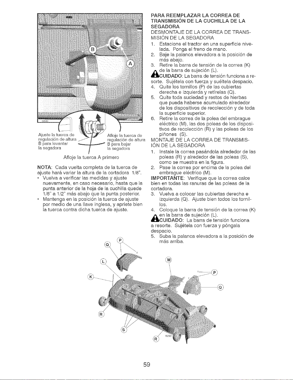
Ajuste Ia tuerca de
regulaci6n de altura _-
B para levantar
la segadora
Afloje la tuerca de
regulaci6n de altura
B para bajar
la segadora
Afloje la tuerca A primero
NOTA: Cada vuelta completa de la tuerca de
ajuste hat#. variar la altura de la cortadora 1/8".
Vuelva a verificar las medidas y ajuste
nuevamente, en case necesario, hasta que la
punta anterior de la hoja de la cuchilla quede
1/8" a 1/2" m6.s abajo que la punta posterior.
Mantenga en la posici6n la tuerca de ajuste
per medio de una Ilave inglesa, y apriete bien
la tuerca contra dicha tuerca de ajuste.
PARA REEMPLAZAR LA CORREA DE
TRANSMISl6N DE LA CUCHILLA DE LA
SEGADORA
DESMONTAJE DE LA CORREA DE TRANS-
MISION DE LA SEGADORA
1. Estacione el tractor en una superficie nive-
lada. Ponga el freno de mane.
2. Baje la palanca elevadora a la posici6n de
m&s aba]o.
3. Retire la barra de tensi6n de la correa (K)
_lbde la barra de sujeci6n (L).
OUIDADO: La barra de tensi6n funciona a re-
sorte. Suj@tela con fuerza y su@ltela despacio.
4. Quite los tornillos (P) de las cubiertas
derecha e izquierda y retfrelas (Q).
5. Quite toda suciedad y testes de hierbas
que pueda haberse acumulado alrededor
de los dispositivos de recolecci6n y de toda
la superficie superior.
6. Retire la correa de la polea del embrague
el@ctrico (M), las dos poleas de los disposi-
tivos de recolecci6n (R) y las poleas de los
pifiones (S),
MONTAJE DE LA CORREA DE TRANSMIS-
iON DE LA SEGADORA
1. Instale la correa pas6.ndola alrededor de las
poleas (R) y alrededor de las poleas (S),
come se muestra en la figura.
2. Pase la correa per encima de la polea del
embrague el@ctrico (M).
IMPORTANTE: Verifique que la correa calce
bien en todas las ranuras de las poleas de la
cortadora.
3. Vuelva a colocar las cubiertas derecha e
izquierda (Q). Ajuste bien todos los tornil-
los.
4. Coloque la barra de tensi6n de la correa (K)
_en la barra de sujeci6n (L).
OUIDADO: La barra de tensi6n funciona
a resorte. Suj@tela con fuerza y p6ngala
despacio.
5. Suba la palanca elevadora a la posici6n de
m#.s arriba.
\\
\
59
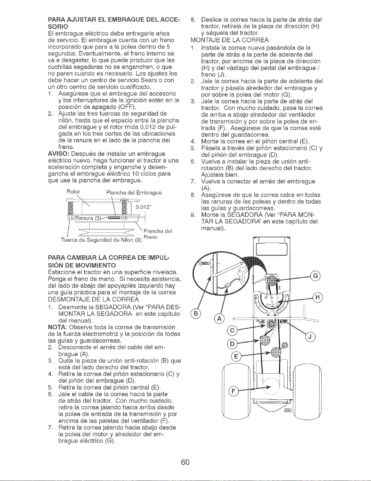
PARA AJUSTAR EL EMBRAGUE DEL ACCE-
SORIO
El embrague electrico debe entregarle ahos
de servicio. El embrague cuenta con un freno
incorporado que para a la polea dentro de 5
segundos. Eventualmente, el freno interno se
va a desgastar, Io que puede producir que las
cuchillas segadoras no se enganchen, o que
no paten cuando es necesario. Los ajustes los
debe hacer un centro de servicio Sears o con
un otto centro de servicio cualificado.
1. AsegQrese que el embrague del accesorio
y los interruptores de la ignici6n esten en la
posici6n de apagado (OFF).
2. Ajuste las tres tuercas de seguridad de
nil6n, hasta que el espacio entre la plancha
del embrague y el rotor mida 0,012 de pul-
gada en los tres cortes de las ubicaciones
de la ranura en el lado de la plancha del
freno.
AVISO: Despues de instalar un embrague
electrico nuevo, haga funcionar el tractor a una
aceleraci6n completa y enganche y desen-
ganche el embrague electrico 10 ciclos para
que use la plancha del embrague.
Rotor Plancha del Embrague
0,012"
i_LRar_ ' 1_ _Plancha
Ranura (3) -I
de!
Tuerca de Seguridad de Nilon (3) Freno
8. Deslice la correa hacia la parte de atras del
tractor, retfrela de la placa de direcci6n (H)
y saquela del tractor.
MONTAJE DE LA CORREA
1. Instale la correa nueva pas#,ndola de la
parte de atr_.s a la parte de adelante del
tractor, pot encima de la placa de direcci6n
(H) y del v#,stago del pedal del embrague /
freno (J).
2. Jale la correa hacia la parte de adelante del
tractor y pasela alrededor del embrague y
pot sobre la polea del motor (G).
3. Jale la correa hacia la parte de atr#.s del
tractor, Con mucho cuidado, pase la correa
de arriba a abajo alrededor del ventilador
de transmisi6n y pot sobre la polea de en-
trada (F). AsegOrese de que la correa este
dentro del guardacorrea.
4. Monte la correa en el pi_6n central (E).
5. Pasela a traves del pi_6n estacionario (C) y
del piffl6n del embrague (D).
6. Vuelva a instalar la pieza de uni6n anti-
rotaci6n (B) del lade derecho del tractor.
AjQstela bien.
7. Vuelva a conectar el ames del embrague
(A).
8. AsegOrese de que la correa calce en todas
las ranuras de las poleas y dentro de todas
las guias y guardacorreas.
9. Monte la SEGADORA (Vet "PARA MON-
TAR LA SEGADOR,_' en este cap[tulo del
manual).
PARA CAMBIAR LA CORREA DE IMPUL-
SION DE MOVIMIENTO
Estacione el tractor en una superficie nivelada.
Ponga el freno de mano. Si necesita asistencia,
del lado de abajo del apoyapies izquierdo hay
una guia pr6.ctica para el montaje de la correa
DESMONTAJE DE LA CORREA
1. Desmonte la SEGADORA (Ver"PARA DES-
MONTAR LA SEGADORA en este capftulo
del manual).
NOTA: Observe toda la correa de transmisi6n
de la fuerza electromotriz y la posici6n de todas
las guias y guardacorreas.
2. Desconecte el ames del cable del em-
brague (A).
3. Quite la pieza de uni6n anti-rotaci6n (B) que
est& del lado derecho del tractor.
4. Retire la correa del pi_i6n estacionario (C) y
del pi_6n del embrague (D).
5. Retire la correa del pi_6n central (E).
6. Jale el cable de la correa hacia la parte
de atr&s del tractor. Con mucho cuidado,
retire la correa jalando hacia arriba desde
la polea de entrada de la transmisi6n y pot
encima de las paletas del ventilador (F).
7. Retire la correa jalando hacia abajo desde
la polea del motor y alrededor del em-
brague electrico (G).
60
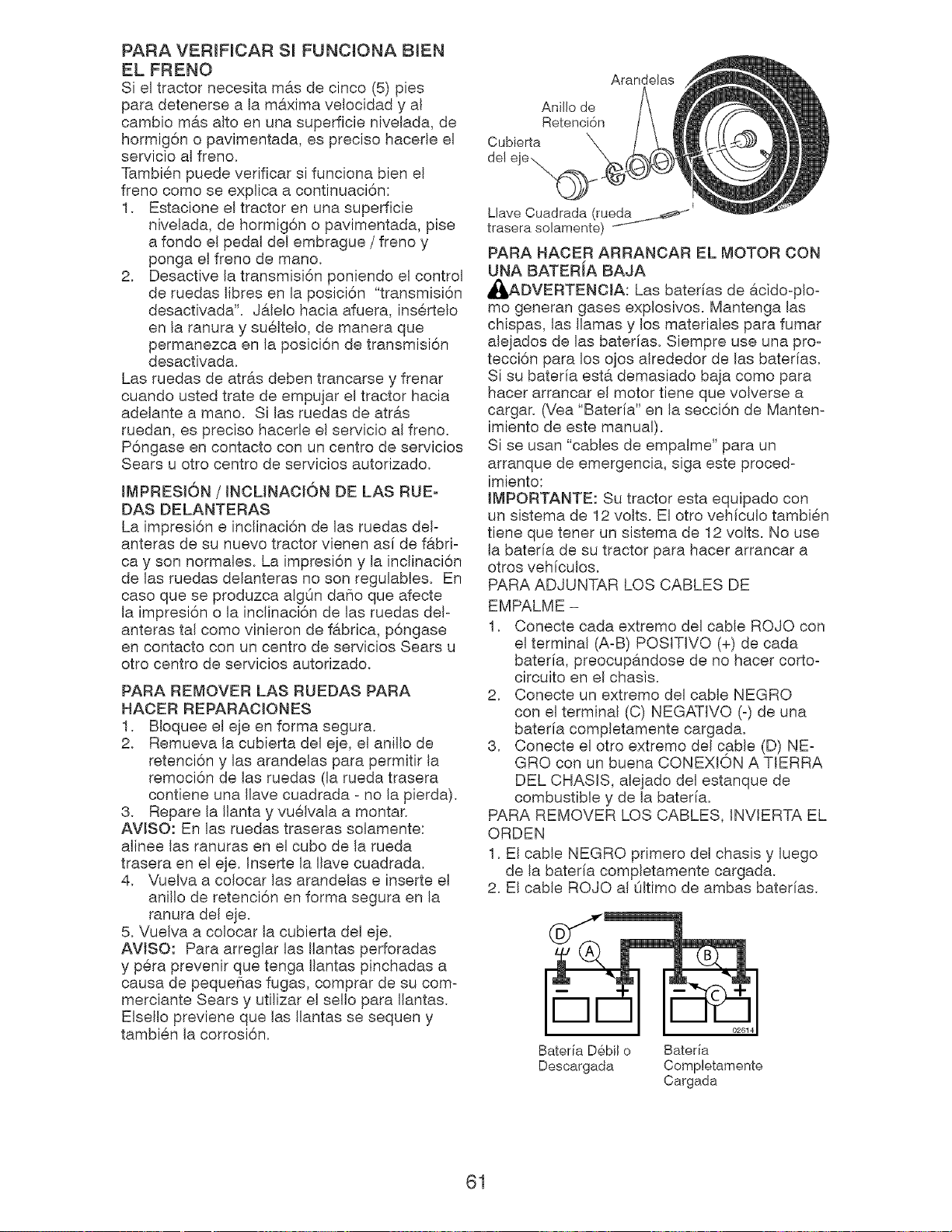
PARA VERIFICAR Sl FUNCIONA BIEN
EL FRENO
Si el tractor necesita m&s de cinco (5) pies
para detenerse a la m&xima velocidad y al
cambio m&s alto en una superficie nivelada, de
hormig6n o pavimentada, es preciso hacede el
servicio al freno.
Tambien puede verificar si funciona bien el
freno come se explica a continuaci6n:
1. Estacione el tractor en una superficie
nivelada, de hormig6n o pavimentada, pise
a fondo el pedal del embrague / freno y
ponga el freno de mano.
2. Desactive la transmisi6n poniendo el control
de ruedas Iibres en la posici6n "transmisi6n
desactivada'. Jalelo hacia afuera, insertelo
en la ranura y sueltelo, de manera que
permanezca en la posici6n de transmisi6n
desactivada.
Las ruedas de atr&s deben trancarse y frenar
cuando usted trate de empujar el tractor hacia
adelante a mano. Si las ruedas de atras
ruedan, es preciso hacede el servicio al freno.
P6ngase en contacto con un centro de servicios
Sears u otto centro de servicios autorizado.
IMPRESlON / INCLINACION DE LAS RUE-
DAS DELANTERAS
La impresi6n e inclinaci6n de las ruedas deF
anteras de su nuevo tractor vienen asf de f&bd-
ca y son normales. La impresi6n y la inclinaci6n
de las ruedas delanteras no son regulables. En
caso que se produzca algOn daflo que afecte
la impresi6n o la inclinaci6n de las ruedas deF
anteras tal como vinieron de fabrica, p6ngase
en contacto con un centro de servicios Sears u
otto centro de servicios autorizado.
PARA REMOVER LAS RUEDAS PARA
HACER REPARACIONES
1. Bloquee el eje en forma segura.
2. Remueva la cubierta del eje, el anillo de
retenci6n y las arandelas para permitir la
remoci6n de las ruedas (la rueda trasera
contiene una Ilave cuadrada - no la pierda).
3. Repare la Ilanta y vuelvala a montar.
AVlSO: En las ruedas traseras solamente:
alinee las ranuras en el cubo de la rueda
trasera en el eje. Inserte la Ilave cuadrada.
4. Vuelva a colocar las arandelas e inserte el
anillo de retenci6n en forma segura en la
ranura del eje.
5. Vuelva a colocar la cubierta del eje.
AWSO: Para arreglar las Ilantas perforadas
y pera prevenir que tenga Ilantas pinchadas a
causa de pequeflas fugas, comprar de su com-
merciante Sears y utilizar el sello para Ilantas.
Elsello previene que las Ilantas se sequen y
tambien la corrosi6n.
Arandelas
Anillo de
Retenci6n
Cubierta
de! eje .....@
Llave Ouadrada (rueda _
trasera solamente)
PARA HACER ARRANCAR EL MOTOR CON
UNA BATERiA BAJA
_DVERTENCIA: Las baterias de acidooploo
me generan gases explosivos, Mantenga las
chispas, las llamas y los materiales para fumar
alejados de las baterias, Siempre use una pro-
tecci6n para los ojos alrededor de las baterias,
Si su baterfa esta demasiado baja come para
hacer arrancar el motor tiene que volverse a
cargar. (Yea "Bateria" en la secci6n de Mantem
imiento de este manual).
Si se usan "cables de empalme" para un
arranque de emergencia, siga este proced-
imiento:
IMPORTANTE: Su tractor esta equipado con
un sistema de 12 volts. El otto vehiculo tambien
tiene que tenet un sistema de 12 volts. No use
la baterfa de su tractor para hacer arrancar a
otros vehiculos.
PARA ADJUNTAR LOS CABLES DE
EMPALME -
1. Conecte cada extremo del cable ROJO con
el terminal (A-B) POSMVO (+) de cada
baterfa, preocupandose de no hacer corto-
circuito en el chasis.
2. Conecte un extreme del cable NEGRO
con el terminal (C) NEGATWO (-) de una
bateria completamente cargada.
3. Conecte el otto extremo del cable (D) NE-
GRO con un buena CONEXION A TIERRA
DEL CHASIS, alejado del estanque de
combustible y de la bateria.
PARA REMOVER LOS CABLES. INVlERTA EL
ORDEN
1. El cable NEGRO primero del chasis y luego
de la baterfa completamente cargada.
2. El cable ROJO al Oltimo de ambas baterias.
rq
Bateria D6bil o Bateria
Descargada Completamente
Cargada
61
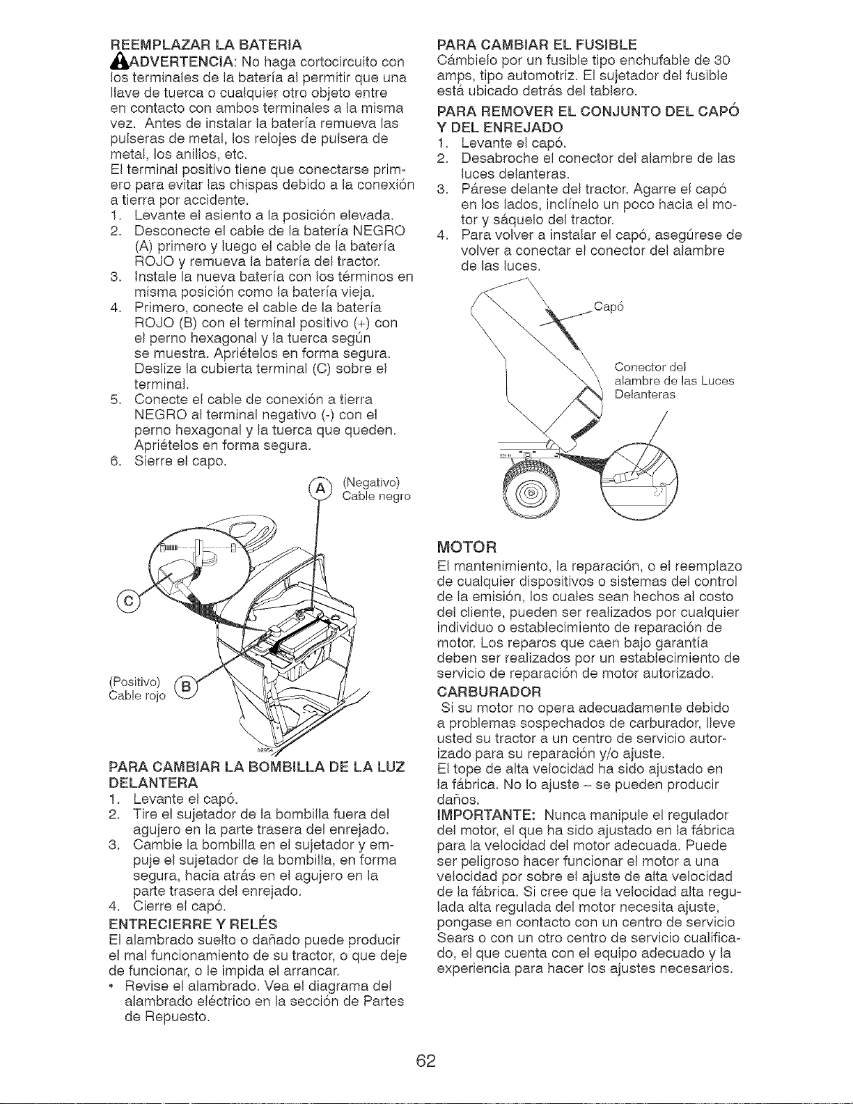
REEMPLAZAR LA BATERIA
_bADVERTENCIA: No haga cortocircuito con
los terminales de la baterfa al permitir que una
Ilave de tuerca o cualquier otto objeto entre
en contacto con ambos terminales a la misma
vez. Antes de instalar la bater[a remueva las
pulseras de metal, los relojes de pulsera de
metal, los anillos, etc.
El terminal positivo tiene que conectarse prim-
ere para evitar las chispas debido a la conexi6n
a tierra pot accidente.
1. Levante el asiento a la posici6n elevada.
2. Desconecte el cable de la baterfa NEGRO
(A) primero y luego el cable de la baterfa
ROJO y remueva la bateria del tractor,
3. Instale la nueva bateria con los t@rminos en
misma posici6n come la baterfa vieja.
4. Primero, conecte el cable de la baterfa
ROJO (B) con el terminal positivo (+) con
el pemo hexagonal y la tuerca segOn
se muestra. Apri@telos en forma segura.
Deslize la cubierta terminal (C) sobre el
terminal.
5. Conecte el cable de conexi6n a tierra
NEGRO al terminal negative (°) con el
perno hexagonal y la tuerca que queden.
Apri@telos en forma segura.
6. Sierre el capo.
(Negativo)
Cable negro
PARA CAMBJAR EL FUSIBLE
Cambielo pot un fusible tipo enchufable de 30
amps, tipo automotriz. El sujetador del fusible
PARA REMOVER EL OONJUNTO DEL OAPO
Y DEL ENREJADO
1. Levante el cap6.
2. Desabroche el conector del alambre de las
luces delanteras.
3. P#,rese delante del tractor. Agarre el cap6
en los lados, inclinelo un poco hacia el moo
tory s#,quelo del tractor,
4. Para volver a instalar el cap6, asegOrese de
volver a conectar el conector del alambre
de las luces.
Conector del
alambre de las Luces
Delanteras
(Positivo)
Oab!e rojo
PARA CAMBIAR LA BOMBILLA DE LA LUZ
DELANTERA
1. Levante el cap6.
2. Tire el sujetador de la bombilla fuera del
agujero en la parte trasera del enrejado.
3. Cambie la bombilla en el sujetador y em-
puje el sujetador de la bombilla, en forma
segura, hacia atr&s en el agujero en la
parte trasera del enrejado.
4. Cierre el cap6.
ENTREOIERRE Y RELES
El alambrado suelto o da_iado puede producir
el mal funcionamiento de su tractor, o que deje
de funcionar, o le impida el arrancar.
Revise el alambrado. Vea el diagrama del
alambrado el@ctrico en la secci6n de Partes
de Repuesto.
MOTOR
El mantenimiento, la reparaci6n, o el reemplazo
de cualquier dispositivos o sistemas del control
de la emisi6n, los cuales sean hechos al costo
del cliente, pueden set realizados pot cualquier
individuo o establecimiento de reparaci6n de
motor. Los reparos que caen bajo garantfa
deben set realizados pot un establecimiento de
servicio de reparaci6n de motor autorizado.
OARBURADOR
Si su motor no opera adecuadamente debido
a problemas sospechados de carburador, Ileve
usted su tractor a un centro de servicio autor°
izado para su reparaci6n y/o ajuste.
El tope de alta velocidad ha sido ajustado en
la fabrica. No Io ajuste - se pueden producir
daSos.
IMPORTANTE: Nunca manipule el regulador
para la velocidad del motor adecuada. Puede
set peligroso hacer funcionar el motor a una
velocidad per sobre el aiuste de alta velocidad
de la fabrica. Si cree que la velocidad alta regu-
lada alta regulada del motor necesita ajuste,
pongase en contacto con un centro de servicio
Sears o con un otto centro de servicio cualifica°
do, el que cuenta con el equipo adecuado y la
experiencia para hacer los ajustes necesarios.
62
Inmediatamente prepare su tractor para el
almacenamiento al final de la temporada o si el
tractor no se va a usar pot 30 dias o mas.
_DVERTENOIA: Nunca almacene el trac-
tor con gasolina en el estanque dentro de un
edificio en donde los gases pueden alcanzar
una llama expuesta ouna chispa. Permita que
el motor se enfrie antes de almacenado en
cualquier recinto privado.
TRACTOR
Cuando el tractor se va a almacenar per cierto
periode de tiempo, limpiela cuidadosamente,
quite toda la mugre, la grasa, las hojas, etc.
Guardela en una #,tea limpia y seca.
1. Limpie todo el tractor (vea "LIMPIEZ_' en la
secci6n de Mantenimiento en este manual).
2. Inspeccione y cambie las correas, si es
necesario (vea las instrucciones para el
cambio de las correas en la secci6n de
Servicio y Ajustes de este manual).
3. Lubrfquelo, segOn se muestra en la secci6n
de Mantenimiento de este manual.
4. AsegOrese que todas las tuercas, los
pernos y los tornillos esten sujetados
en forma segura. Inspeccione las partes
movibles para verificar si hay daho, rotura o
desgaste. C6.mbielas si es necesario.
5. Retoque todas superficies pintadas oxida-
das o picadas; aplique lija antes de pintar.
Cargue la bateria completamente antes de
guardarla.
Despues de cierto periodo de tiempo en
almacenamiento, la bateria puede necesitar
volver a cargarse.
Para ayudar a evitar la corrosi6n y las fugas
de potencia durante largos periodos de
almacenamiento, se deben desconectar
los cables de la bateria y se debe limpiar
cuidadosamente (vea "PARA LIMPIAR LA
BATER[A Y LOS TERMINALES" en la sec-
ci6n de Mantenimientode este manual).
Despues de limpiarla, deje los cables desco-
nectados y p6ngalos en donde no puedan
entrar en contacto con los terminales de la
bateria.
Si se remueve la bateria del tractor para el
almacenamiento, no la guarde directamente
sobre concreto o sobre superficies hOmedas.
MOTOR
SJSTEMA DE COMBUSTIBLE
IMPORTANTE: Es important evitar que se
forman depositos de goma en partes funda-
mentales del sistema de combus-tible tales
como el carburador, el filtro del combustible,
la manguera del combustibles mezclados con
alcohol (conocido como gasohol o que tienen
etanol o metanol) pueden atraer humedad, Io
que conduce a la separaci6n y a la formaci6n
de acudos durante elalmacenamiento. La
gasolina acidica puede da_ar el sistema de
combustible de un motor durante el periodo de
almacenamiento.
Vaciar el dep6sito del carburante poniendo
en marcha el motor y dejandolo funcionar
hasta que el carburante termine el carbura-
dot este vacio.
Nunca use los productos para limpieza del
carburador o del motor en el estanque de
combustible pues se pueden producir da_os
permanentes.
Use combustible nuevo la pr6xima
temporada.
AWSO: El estabilizador de combustible es una
alternativa aceptable para reducir a un minimo
la formaci6n de dep6sitos de goma en el com-
bustible durante el periodo de almacenamiento.
Agregue estabilizador a la gasolina en el
estanque de combustible o en el envase para el
almacenamiento. Siempre siga la proporci6n de
mezcla que se encuentra en el envase del esta-
bilizador. Haga funcionar el motor pot Io menos
10 minutos despues de agregar el estabilizador,
para permitir que este Ilegue al carburador. No
vaciar la gasolina del estanque de gasolina y el
carburador si se esta usando estabilizador de
combustible.
AGEITE DEL MOTOR
Drene el aceite (con el motor ealiente) y
cambielo con aceite de motor limpio, (Vea "MO-
TOR" en la secci6n de Mantenimiento" de este
manuaL)
ClLINDRO(S)
1. Remueva la(s) bujia(s).
2. Vade una onza de aceite a traves del
agujero(s) de la bujia en el cilindro(s).
3. Gire la Ilave de ignici6n a la posici6n de 'mr-
ranque" (Start), per unos cuantos segundos
para distribuir el aceite.
4. Cambie per bujia(s) nueva(s).
OTROS
No guarde la gasolina de una temporada a la
otra.
Cambie el envase de la gasolina si se emp-
ieza a oxidar. La oxidaci6n y/o la mugre en
su gasolina produciran problemas.
Si es posible, guarde su unidad en un recinto
cerrado y cObrala para protegerla contra el
polvo y la mugre.
Cubra su unidad con un forro protector
adecuado que no retenga la humedad. No
use pl#.stico. El pl#.stico no puede respirar, Io
que permite la formaci6n de condensaci6n,
Io que producira la oxidaci6n de su unidad.
IMPORTANTE: Nunca cubra el tractor mientras
el motor y las areas de escape todavia estan
calientes.
63
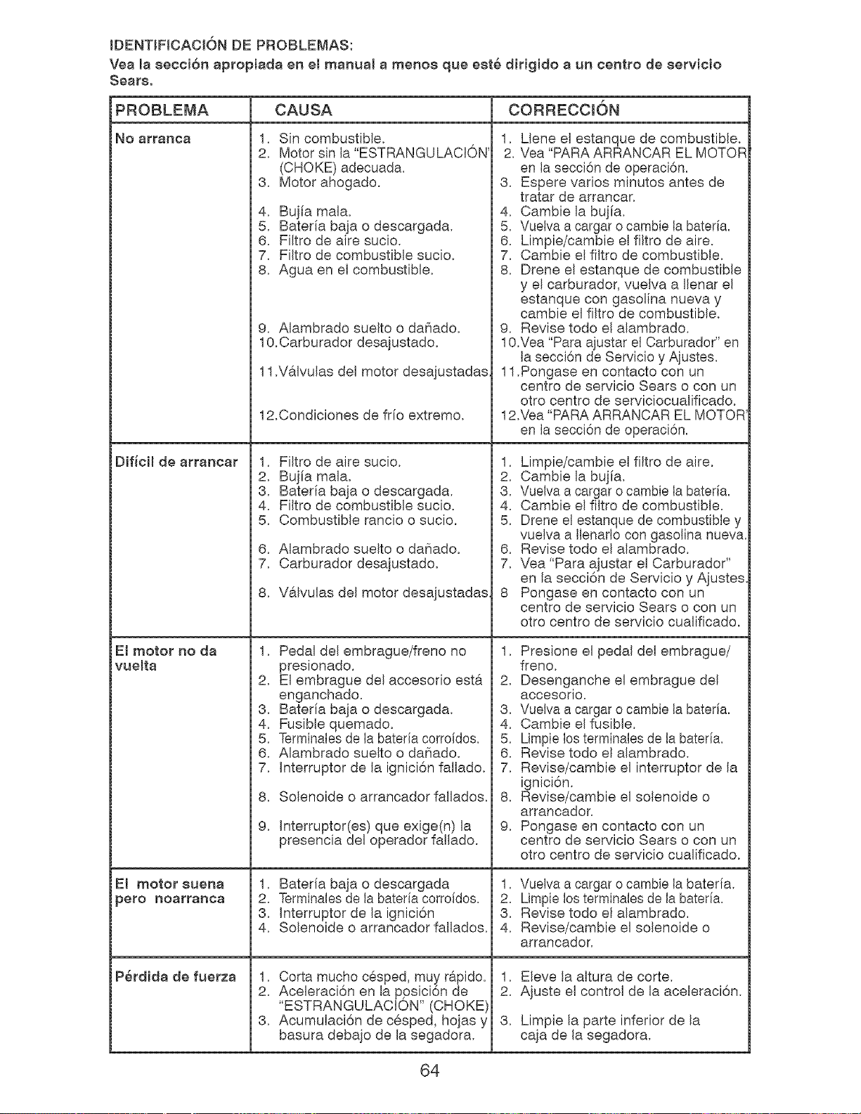
IDENTIFICACION DE PROBLEMAS:
Yea masecci6n apropiada en el manual a menos que est6 dirigido a un centro de eervicio
CAUSA CORRECCION
No arranca
Dificil de arrancar
El motor no da
vuelta
El motor suena
_ero 13oarranca
1. Sin combustible.
2. Motor sin la "ESTRANGULACION'
(CHOKE) adecuada.
3. Motor ahogado.
4. Bujia mala.
5. Bateria baja o descargada.
6. Filtro de aire sucio.
7. Filtro de combustible sucio.
8. Agua en el combustible.
P6rdida de fuerza
9. Aiambrado suelto o daSado.
10.Carburador desajustado.
11.V&lvulas del motor desajustadas
12.Condiciones de fr[o extremo.
1. Filtro de aire sucio.
2. Buj[a mala.
3. Bateria baja o descargada.
4. Filtro de combustible sucio.
5. Combustible rancio o sucio.
6. Alambrado suelto o daSado.
7. Carburador desajustado.
8. V&lvulas del motor desajustadas
1. Pedal del embrague/freno no
presionado.
2. El embrague del accesodo esta
enganchado.
3. Bateria baja o descargada.
4. Fusible quemado.
5. Terminales de la bateria corroidos.
6. Alambrado suelto o da_iado.
7. Interruptor de la ignici6n fallado.
8. Solenoide o arrancador fallados.
9.
Interruptor(es) que exige(n) la
presencia del operador fallado.
1. Bater[a baja o descargada
2. Terminales de la bateria corroidos.
3. Interruptor de la ignici6n
4. Solenoide o arrancador fallados.
1. Corta mucho cesped, muy rapido.
2. Aceleraci6n en la ppsici6n de
"ESTRANGULACION" (CHOKE)
3. Acumulaci6n de cesped, hojas y
basura debajo de la segadora.
1. Llene el estanque de combustible.
2. Vea "PARA ARRANCAR EL MOTOR
en la secci6n de operaci6n.
3. Espere varies minutos antes de
tratar de arrancar.
4. Cambie la bujia.
5. Vuelva a cargar o cambie la bateria.
6. Limpie/cambie el filtro de aire.
7. Cambie el filtro de combustible.
8. Drene el estanque de combustible
y el carburador, vueiva a Iienar el
estanque con gasolina nueva y
cambie el filtro de combustible.
9. Revise todo el alambrado.
10.Vea "Para ajustar el Carburador" en
la secci6n de Servicio y Ajustes.
11.Pongase en contacto con un
centro de servicio Sears o con un
otto centro de serviciocualificado.
12.Vea "PARA ARRANCAR EL MOTOR
en la secci6n de operaci6n.
1. Limpie/cambie el filtro de aire.
2. Cambie la bujia.
3. Vuelva a cargar o cambie la bateria.
4. Cambie el filtro de combustible.
5. Drene el estanque de combustible y
vuelva a llenado con gasolina nueva.
6. Revise todo el alambrado.
7. Vea "Para ajustar el Carburador"
en la secci6n de Servicio y Aiustes
8 Pongase en contacto con un
centro de servicio Sears o con un
otro centro de servicio cualificado.
1. Presione el pedal del embrague/
freno.
2. Desenganche el embrague del
accesorio.
3. Vuelva a cargar o cambie la bateria.
4. Cambie el fusible.
5. Limpie los terminales de la bateria.
6. Revise todo el alambrado.
7. Revise/cambie el interruptor de la
ignici6n.
8. Revise/cambie el solenoide o
arrancador.
9. Pongase en contacto con un
centro de servicio Sears o con un
otto centro de servicio cualificado.
1. Vuelva a cargar o cambie la bateria.
2. Limpie los terminales de la bateria.
3. Revise todo el alambrado.
4. Reviseicambie el solenoide o
arrancador.
1. Eleve la altura de corte.
2. Ajuste el control de la aceleraci6n.
3.
Limpie la parte inferior de la
caja de la segadora.
64
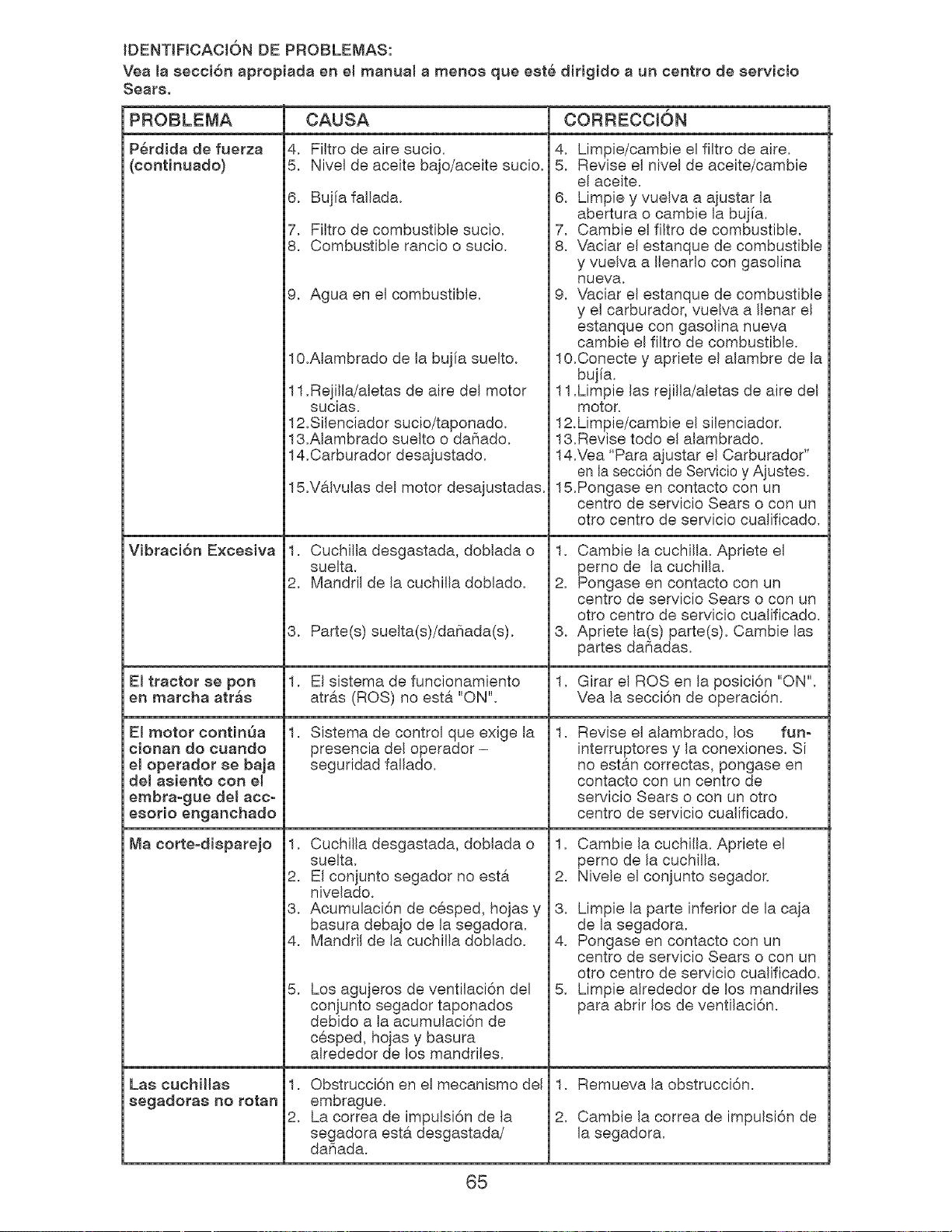
IDENTIFICACI6N DE PROBLEMAS:
Vea la secci6n apropiada en emmanual a menoe que eet6 dirigido a un centro de eervicio
Sears.
PROBLEMA
P6rdida de fuerza
(continuado)
Vibraci6n Excesiva
CAUSA
4. FiJtro de aire sucio.
5. Nivel de aceite bajo/aceite sucio.
6. Bujia fallada.
7. Filtro de combustible sucio.
8. Combustible rancio o sucio.
9. Agua en el combustible.
10.Alambrado de la bujfa suelto.
11.Rejilla/aletas de aire del motor
sucias.
12.Silenciador sucio/taponado.
13.Alambrado suelto o daSado.
14.Carburador desajustado.
15.V&lvulas del motor desajustadas.
1. Cuchilla desgastada, doblada o
suelta.
2. Mandril de la cuchilla doblado.
8. Parte(s) suelta(s)/daSada(s).
CORRECCK_N
4. Limpie/cambie el filtro de aire.
5. Revise el nivel de aceite/cambie
el aceite.
6. Limpie y vuelva a ajustar la
abertura o cambie la buj[a.
7. Cambie el filtro de combustible.
8. Vaciar el estanque de combustible
y vuelva a Ilenarlo con gasolina
nueva.
9. Vaciar el estanque de combustible
y el carburador, vuelva a Ilenar el
estanque con gasolina nueva
cambie el filtro de combustible.
lO.Conecte y apriete el alambre de la
bujia.
11.Limpie las rejilla/aletas de aire del
motor,
12.Limpie/cambie el silenciador.
13.Revise todo el alambrado.
14.Vea "Para ajustar el Carburador"
en la secci6n de Servicio y Ajustes.
15.Pongase en contacto con un
centro de servicio Sears o con un
otro centre de servicio cualificado.
1. Cambie la cuchilla. Apriete el
perno de la cuchilla.
2. Pongase en contacto con un
centre de servicio Sears o con un
otto centro de servicio cualificado.
3. Apriete la(s) parte(s). Cambie las
partes daSadas.
El tractor se port 1. El sistema de funcionamiento 1. Girar el ROSen la posici6n "ON".
en marcha atr_s atr&s (ROS) no est& "ON". Vea la secci6n de operaci6n.
1. Sistema de control que exige la
presencia del operador -
seguridad fallado.
1. Cuchilla desgastada, doblada o
suelta.
2. El conjunto segador no est&
nivelado.
3. Acumulaci6n de cesped, hojas y
basura debajo de la segadora.
4. Manddl de la cuchilla doblado.
Los agujeros de ventilaci6n del
conjunto segador taponados
debido a la acumulaci6n de
cesped, hojas y basura
alrededor de los mandriles.
El motor continSa
cionan do cuando
el operador se baja
del asiento con el
embra-gue del acc-
esorio enganchado
Ma corte-disparejo
5,
1,
Revise el alambrado, los fun-
interruptores y la conexiones. Si
no est&n correctas, pongase en
contacto con un centre de
servicio Sears o con un otro
centre de servicio cualificado.
1. Cambie la cuchHJa, Apriete eJ
perno de Ja cuchilla.
2. Nivele el conjunto segador.
3. Limpie la parte inferior de la caja
de la segadora.
4. Pongase en contacto con un
centro de servicio Sears o con un
otto centro de servicio cualificado.
5. Limpie alrededor de los mandriles
para abrir los de ventilaci6n.
Las cuchiHas 1. Obstrucci6n en el mecanismo del 1. Remueva la obstrucci6n.
segadoras no rotan embrague.
2. La correa de impulsi6n de la 2. Cambie la correa de impulsi6n de
segadora est& desgastada/ la segadora.
daSada.
65
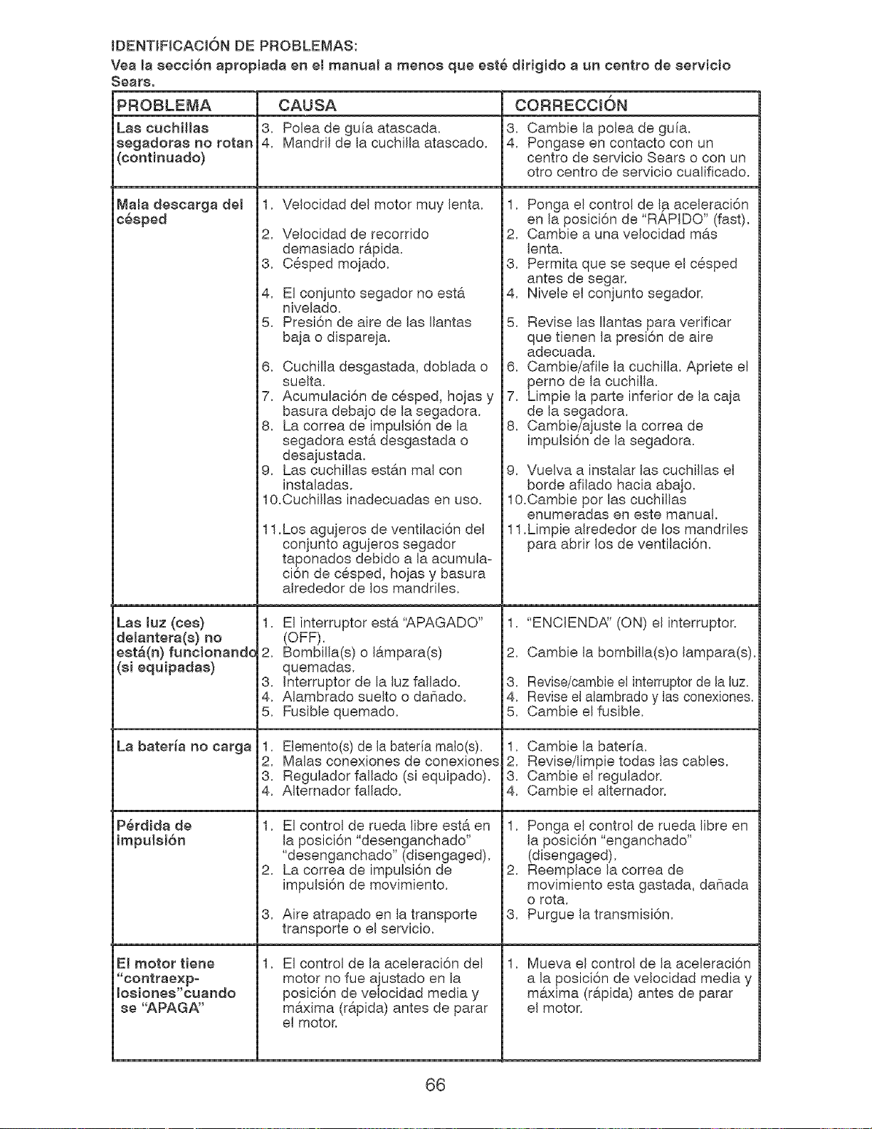
IDENTIFICACION DE PROBLEMAS:
Yea masecci6n apropiada en el manual a menos que est6 dirigido a un centro de servicio
Las cuchillas
segadoras no rotan
(continuado)
Mala descarga del
c_sped
Las muz(ces)
delantera(s) no
est.(n) funcionando
(si equipadas)
La bater_a no carga
El motor tiene
"contraexp-
Io8}ones"ouando
se "APAGA"
CAUSA
3. Polea de guia atascada.
4. Mandril de la cuchilla atascado.
1. Velocidad del motor muy lenta.
2. Velocidad de recorrido
demasiado r#,pida.
3. Cesped mojado.
4. El conjunto segador no est&
nivelado.
5. Presi6n de aire de las Ilantas
baja o dispareja.
6. Cuchilla desgastada, doblada o
suelta.
7. Acumulaci6n de cesped, hojas y
basura debajo de la segadora.
8. La correa de impulsi6n de la
segadora est& desgastada o
desajustada.
9. Las cuchillas estan mal con
instaladas.
10.Cuchillas inadecuadas en uso.
11
.Los agujeros de ventilaci6n del
conjunto agujeros segador
taponados debido a la acumula=
ci6n de cesped, hojas y basura
alrededor de los mandriles.
1. El interruptor est& '_,PAGADO"
(OFF).
2. Bombilla(s) o lampara(s)
quemadas.
3. Interruptor de la luz fallado.
4. Alambrado suelto o daSado.
5. Fusible quemado.
1. Elemento(s) de la bateria malo(s).
2. Malas conexiones de conexiones
3. Regulador fallado (si equipado).
4. Alternador fallado.
1.
2.
3.
El control de rueda libre est& en
la posici6n "desenganchado"
"desenganchado" (disengaged).
La correa de impulsi6n de
impulsi6n de movimiento.
Aire atrapado en la transporte
transporte o el servicio.
El control de la aceleraci6n del
motor no fue ajustado en la
posici6n de velocidad media y
m&xima (rapida) antes de parar
el motor.
CORRECCK)N
3.
4.
Cambie la polea de guia.
Pongase en contacto con un
centro de servicio Sears o con un
otto centro de servicio cualificado.
1. Ponga el control de la aceleraci6n
en la posici6n de "RAPIDO" (fast).
2. Cambie a una velocidad m&s
lenta.
3. Permita que se seque el cesped
antes de segar.
4. Nivele el conjunto segador.
5. Revise las Ilantas para verificar
que tienen la presi6n de aire
adecuada.
6. Cambie/afile la cuchilla. Apriete el
perno de la cuchilla.
7. Limpie la parte inferior de la caja
de la segadora.
8. Cambie/ajuste la correa de
impulsi6n de la segadora.
9. Vuelva a instalar las cuchillas el
borde afilado hacia abajo.
lO.Cambie por las cuchillas
enumeradas en este manual.
11.Limpie alrededor de los manddles
para abrir los de ventilaci6n.
1. "ENCIENDA" (ON) el interruptor.
2. Cambie la bombilla(s)o lampara(s).
3. Revise/cambie el interrupter de la luz.
4. Revise el alambrado y las conexiones.
5. Cambie el fusible.
1. Cambie la bater[a.
2. Revise/limpie todas las cables.
3. Cambie el regulador.
4. Cambie el alternador.
1. Ponga el control de rueda libre en
la posici6n "enganchado"
(disengaged).
2. Reemplace la correa de
movimiento esta gastada, daSada
o rota.
3. Purgue la transmisi6n.
1. Mueva el control de la aceleraci6n
a la posici6n de velocidad media y
m&xima (r&pida) antes de parar
el motor.
66
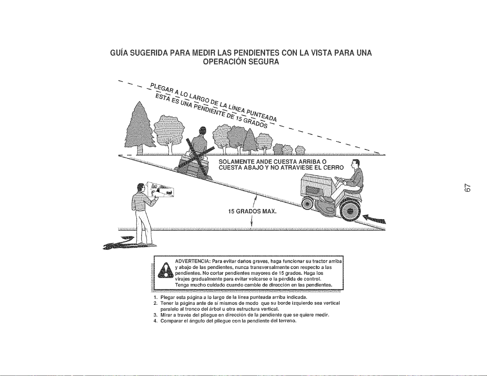
GUiA $UGERmDAPAFtAMEDIRLAS PENDIENTES CON LA VISTA PARA UNA
OPEFtACI6N SEGURA
$OLAMENTE ANDE CUESTA ARRiBA O
CUESTA ABAJO Y NO ATRAViESE EL CERRO
CO
1. Plegar asta pagina alo largo de la iinea punteada arfiba {ndicada.
2. Tenor _apagina ante de ei miemos de mode qua su horde izquierdo sea verticat
paratele al tronco del arbe_ u otra eetractura vertical
3. Mirar a traves dab pliegue en direcc{6n de la pendiente que ee quiera medir.
4. Comparar e_ angule del pliegae con Ja pendiente del tarreno.

LLLLLLLLLLiLL,_'_
iiiiiiiiiiiiiiiiiiiiii'
iiiiiiiiiiiiiiiiiiii_'
iiiiiiiiiiiiiiiiiiii
iiiiiiiiiiiiiiiiiiii
iiiiiiiiiiiiiiiiiiii
iiiiiiiiiiiiiiiiiiii
iiiiiiiiiiiiiiiiiiii
iiiiiiiiiiiiiiiiiiii
iiiiiiiiiiiiiiiiiiii
iiiiiiiiiiiiiiiiiiii
iiiiiiiiiiiiiiiiiiii
iiiiiiiiiiiiiiiiiiii
iiiiiiiiiiiiiiiiiiii
iiiiiiiiiiiiiiiiiiii
iiiiiiiiiiiiiiiiiiii
iiiiiiiiiiiiiiiiiiii
iiiiiiiiiiiiiiiiiiiiiiiiiiiiiiiii_i
iiiiiiiiiiiiiiiiiiiiiiiiiiiiiiiii_i
Your Home
© Sears Brands, LLC
® Registered Trademark / TMTrademark / SM Service Mark of Sears Brands, LLC
® Marca RegJstrada / TM Marca de Fabrica / SM Marca de Servicio de Sears Brands, LLC
MC Marque de commerce / MD Marque deposee de Sears Brands, LLC
409496 10.26.06 AP Printed in U.S.A.