ENGUSH ...................................... 3
FRAN(_AIS ................................. 12
ESPANOL ................................... 21
RroanoNuTone LLC. 926 West State Street, Hartford, Wt 53027
NuTone, Inc., 4820 Red Rank Road, Cincinnati, OH 45227
Rroan-NuTone Canada, IN0.1140 Tristar Drive, Mississauga, Ontario, LST 1H9

WARNING WARNING
SUITABLE FOR USE IN HOUSEHOLD
COOKING AREA.
TO REDUCETHE RISK OF FIRE, ELECTRICAL
SHOCK, OR INJURY TO PERSONS, OBSERVE
THE FOLLOWING:
1. Use this unit only in the manner intended by
the manufacturer. If you have questions, corn
tact the manufacturer at the address or tele_
phone number listed in the warranty.
2. Before servicing or cleaning unit, switch power
off at service pane! and lock service panel to
prevent power from being switched on
accidentally. When the service disconnecting
means cannot be locked, securely fasten a
prominent warning device, such as a tag, to
the service panel.
3. Installation work and electrical wiring must be
done by a qualified person(s) in accordance
with all applicable codes and standards, includ-
ing fire=rated construction codes and stare
dards.
4. Sufficient air is needed for proper combustion
and exhausting of gases through the flue (chim_
ney) of fuel burning equipment to prevent
backdrafting. Follow the heating equipment
manufacturer's guidelines and safety stare
dards such as those published by the National
Fire Protection Association (NFPA), and the
American Society for Heating, Refrigeration
and Air Conditioning Engineers (ASHRAE), and
the local code authorities.
5. When cutting or drilling into wail or ceiling, do
not damage electrical wiring and other hidden
utilities.
6. Ducted fans must always be vented to the out-
doors.
7. Do not use this unit with any solid=state speed
control device.
8. To reduce the risk of fire, use only steel
ductwork.
9. This unit must be grounded.
TO REDUCE THE RISK OF A RANGE TOP
GREASE FIRE:
A. Never leavesurface unitsunattended athighsettings.
Boilovers cause smoking and greasy spillovers that
mayignite.Heatoilsslowlyon lowor medium settings.
B. AIwaysturn hood ON when cooking athigh heat or
whencooking flaming foods.
C. Clean ventilating fans frequently. Grease should not
beallowed to accumulate onfan or filter.
D. Useproper pansize.Always usecookwareappropriate
for the size ofthe surface element.
TO REDUCE THE RtSK OF INJURY TO PER-
SONS IN THE EVENT OF A RANGE TOP
GREASE FIRE, OBSERVE THE FOLLOWING:*
1. SMOTHER FLAMES with a close=fitting lid,
cookie sheet, or metal tray, then turn off the
burner. BE CAREFULTO PREVENT BURNS.
Ifthe flames do not go out immediately, EVACU=
ATE AND CALLTRE FIRE DEPARTMENT.
2. NEVER PICK UP A FLAMING PAN =You may
be burned.
3. DO NOT USE WATER, including wet dishcloths
or towe!s =vio!ent steam explosion will result.
4. Use an extinguisher ONLY"if:
A. You know you have a C!ass ABC extim
guisher and you already know how to op=
erate it.
B. The fire is small and contained in the area
where it started.
C. The fire department is being called.
D. "Youcan fight the fire with your back to an
exit.
* Based on "Kitchen Fire Safety Tips" pub=
lished by NFPA.
CAUTION
1. To reduce risk of fire and to properly exhaust air,
be sure to duct air outside. Do not vent exhaust
air into spaces within wails or ceilings or into
attics, crawl spaces, or garages.
2. Take care when using cleaning agents or
detergents.
3. Avoid using food products that produce flames
under the Range Rood.
4. For general ventilating use only. Do not use to
exhaust hazardous or explosive materials and
vapors.
5. To avoid motor bearing damage and noisy and/
or unba!anced impellers, keep drywa!l spray,
construction dust, etc. off power unit.
6. Your hood motor has a thermal over!oad which
will automatically shut off the motor if it becomes
overheated.The motor will restart when it cools
down. If the motor continues to shut off and
restart, have the hood serviced.
7. For best capture of cooking impurities, the
bottom of the hood should be a minimum of 24"
and a maximum of 30" above the cooking sur=
face.
8. Two installers are recommended because of the
large size and weight of this hood.
9. Please read specification !abel on product for
further information and requirements.
_3_
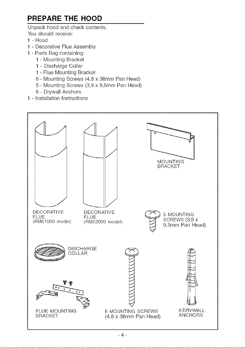
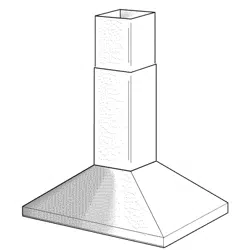
PREPARE THE HOOD
Unpack hood and check contents_
You should receive:
1 - Hood
1 - Decorative Flue Assembly
1 - Parts Bag containing:
1 - Mounting Bracket
1 - Discharge Collar
1 - Flue Mounting Bracket
8 - Mounting Screws (4,8 x 38mm Pan Head)
5 - Mounting Screws (3,9 x 9,Smm Pan Head)
8 - Drywall Anchors
1 - Installation Instructions
DECORATIVE
FLUE
(RM51000 model)
DECORATIVE
FLUE
(RM52000 model)
MOUNTING
BRACKET
_ 5 MOUNTING
SCREWS (3,9 x
9,Smm Pan Head)
DISCHARGE
COLLAR
FLUE MOUNTING
BRACKET
8 MOUNTING SCREWS
(4,8 x 38mm Pan Head)
8 DRYWALL
ANCHORS
-4-
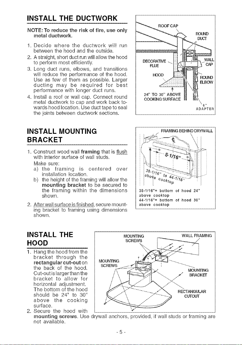
INSTALL THE DUCTWORK
NOTE: To reduce the risk of fire, use only
metal ductwork,
1. Decide where the ductwork will run
between the hood and the outside.
2. A straight, short duct run will allow the hood
to perform most efficiently.
3. Long duct runs, elbows, and transitions
wilI reduce the performance of the hood.
Use as few of them as possible. Larger
ducting may be required for best
performance with longer duct runs.
4. install a roof or wall cap. Connect round
metal ductwork to cap and work back to-
wards hood location. Use duct tape to seal
the joints between ductwork sections.
24" TO 30" ABOVE
COOKING SURFACE
ROUND
@
, !\ _D
=BOW
6"
ADAPTER
INSTALL MOUNTING
BRACKET
1=Construct wood wall framing that is flush
with interior surface of wail studs.
Make sure:
a) the framing is centered over
installation location.
b) the height of the framing wilI allow the
mounting bracket to be secured to
the framing within the dimensions
shown.
2. Afterwall surface is finished secure mount-
ing bracket to framing using dimensions
shown.
FRAMING BEHIND DRYWALL
38oi/16"= bottom of hood 24"
above eooktop
44o1/16"= bottom of hood 30"
above eooktop
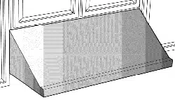
INSTALL THE
HOOD
1. Hang the hood from the
bracket through the
rectangular cut-out on
the back of the hood.
Cut-out islarger than the
bracket to allow for
horizontal adjustment.
The bottom of the hood
should be 24" to 30"
above the cooking
surface.
2. Secure the hood with
mounting screws. Use dr
not available.
MOUNTENG WALL FRAMING
SCREWS
MOUN_NG
SCREWS
MOUN_NG
y'° BRACKET
RECTANGULAR
CUTOUT
fwalI anchors, provided, if wall studs or framing are
-5-
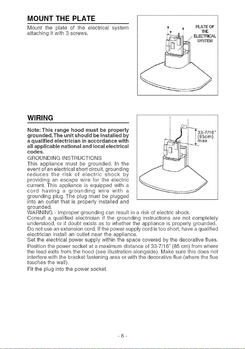
MOUNT THE PLATE
Mount the plate of the electricaI system
attaching it with 3 screws,
PLATE OF
ELECTF_AL
SYSTEM
WIRING
Note: This range hood must be properly
grounded.The unit shoumd be installed by
a qualified electrician in accordance with
all appHcabme national and mocalelectricam
codes.
GROUNDING INSTRUCTIONS
This appliance must be grounded, In the
event of an electrical short circuit, grounding
reduces the risk of electric shock by
providing an escape wire for the electric
current, This appliance is equipped with a
cord having a grounding wire with a
grounding plug, The plug must be plugged
into an outlet that is properly instaIled and
grounded,
WARNING - Improper grounding can result in a risk of electric shock,
ConsuIt a qualified electrician if the grounding instructions are not completely
understood, or if doubt exists as to whether the appliance is properly grounded,
Do not use an extension cord, Ifthe power supply cord is too short, have a qualified
eIectrician install an outlet near the appliance,
Set the electrical power supply within the space covered by the decorative flues,
Position the power socket at a maximum distance of 33-7/16" (85 cm) from where
the Iead exits from the hood (see ilIustration aiongside), Make sure this does not
interfere with the bracket fastening area or with the decorative flue (where the flue
touches the wall),
Fit the plug into the power socket,
-6-
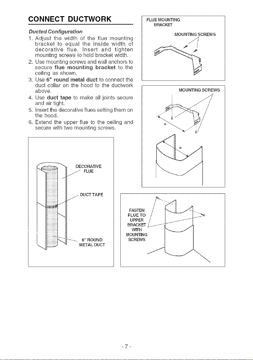
CONNECT DUCTWORK FLUEMOUNTtNG
BRACKET
Ducted Configuration
1. Adjust the width of the flue mounting
bracket to equal the inside width of
decorative flue. insert and tighten
mounting screws to hold bracket width.
2. Use mounting screws and wall anchors to
secure flue mounting bracket to the
ceiling as shown.
3. Use 6" round metal duct to connect the
duct collar on the hood to the ductwork
above.
4. Use duct tape to make alI joints secure
and air tight.
5. Insert the decorative flues setting them on
the hood.
6. Extend the upper ftue to the ceiling and
secure with two mounting screws.
DECORATIVE
FLUE
j DUCTTAPE
6"ROUND
METALDUCT
FASTEN
FLU E TO
UPPER
BRACKET
WrFH
MOUNTING
SCREWS
MOUNTENG SCREWS
MOUNTING SCREWS
-7-
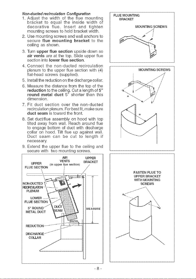
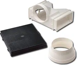
Nomductedrecirculation Configuration
1. Adjust the width of the flue mounting
bracket to equal the inside width of
decorative flue. insert and tighten
mounting screws to hold bracket width.
2. Use mounting screws and wall anchors to
secure flue mounting bracket to the
ceiling as shown.
3. Turn upper flue section upside down so
air vents are at the top. Slide upper flue
section into mowerflue section.
4. Connect the non-ducted recirculation
plenum to the upper flue section with (4)
fiat-head screws (supplied).
5. Install the reduction on the discharge collar.
6. Measure the distance from the top of the
reduction to the ceiling. Cut a iength of 5"
round metal duct 5" shorter than this
dimension.
7. Fit duct section over the non-ducted
recirculation plenum. For best fit, make sure
duct seam is toward the front.
8. Set duct/flue assembly on hood with top
tilted away from wall Reach around flue
to engage bottom of duct with discharge
collar On hood. TiNtflue up against wall.
Duct seam can be cut to length if
necessary.
9. Extend the upper flue to the ceiling and
secure with two mounting screws.
UPPER
FLUE SECTION
AIR UPPER
VENTS BRACKET=
(nnupper Je sectnon)
FLUE SECTION
METAL DUCT
COLLAR
FLUE MOUNTING
BRACKET
MOUNTENG SCREWS
MOUNTING SCREWS
FASTEN FLUE TO
UPPER BRACKET
WiTH MOUNTING
SCREWS
-8-
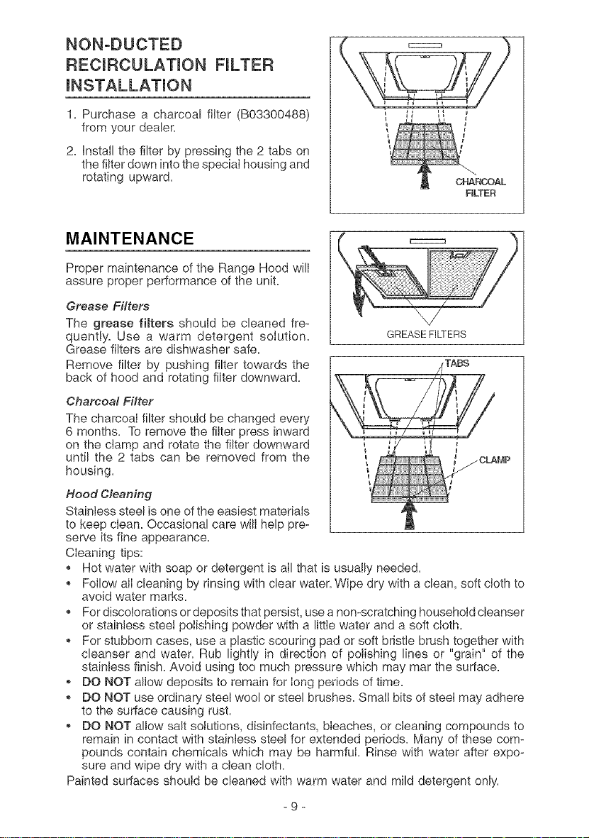
NON°DUCTED
RECmRCULATmON FILTER
mNSTALLATmON
1. Purchase a charcoal filter (B03300488)
from your dealer.
2. InstalI the filter by pressing the 2 tabs on
the filter down into the speciaI housing and
rotating upward.
FILTER
MAINTENANCE
Proper maintenance of the Range Hood wilI
assure proper performance of the unit.
Grease Filters
The grease filters should be cleaned fre-
quently. Use a warm detergent solution.
Grease filters are dishwasher safe.
Remove filter by pushing filter towards the
back of hood and rotating filter downward.
Charcoal Filter
The charcoal filter should be changed every
6 months. To remove the fiiter press inward
on the clamp and rotate the filter downward
until the 2 tabs can be removed from the
housing.
GREASE FILTERS
Hood Cleaning
Stainless steel is one of the easiest materiaIs
to keep clean. Occasional care will help pre-
serve its fine appearance.
Cleaning tips:
, Hot water with soap or detergent is all that is usually needed.
, FoIIow alI cleaning by rinsing with clear water. Wipe dry with a clean, soft cloth to
avoid water marks.
, For discolorations or deposits that persist, use a non-scratching household cteanser
or stainless steel polishing powder with a little water and a soft cloth.
, For stubborn cases, use a plastic scouring pad or soft bristle brush together with
cleanser and water. Rub lightly in direction of polishing lines or "grain" of the
stainless finish. Avoid using too much pressure which may mar the surface.
,, DO NOT allow deposits to remain for long periods of time.
*, DO NOT use ordinary steel wool or steel brushes. Small bits of steel may adhere
to the surface causing rust.
,, DO NOT allow salt solutions, disinfectants, bleaches, or cleaning compounds to
remain in contact with stainless steel for extended periods. Many of these com e
pounds contain chemicals which may be harmfui. Rinse with water after expo-
sure and wipe dry with a clean cloth.
Painted surfaces should be cleaned with warm water and mild detergent only.
-9-
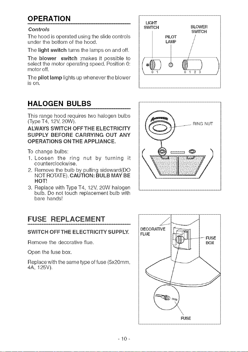
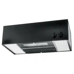
OPERATION
Controls
The hood is operated using the slide controls
under the bottom of the hood.
The light switch turns the lamps on and off.
The blower switch :makes it possible to
select the motor operating speed. Position 0:
motor off.
The pilot lamp lights up whenever the blower
is on.
UGHT
SWrrCH BLOWER
SWrrCH
PILOT
LAMP
01 23
HALOGEN BULBS
This range hood requires two halogen buibs
(Type T4, 12V,20W)+
ALWAYS SWITCH OFFTHE ELECTRICITY
SUPPLY BEFORE CARRYING OUT ANY
OPERATIONS ON THE APPLIANCE.
To change bulbs:
1. Loosen the ring nut by turning it
counterclockwise+
2. Remove the bulb by pulling sideward(DO
NOT ROTATE).CAUTION: BULB MAY BE
HOT!
3+ Replace with Type T4, 12V, 20W halogen
bulb+ Do not touch replacement bulb with
bare hands!
FUSE REPLACEMENT
SWITCH OFFTHE ELECTRICITY SUPPLY.
Remove the decorative flue+
Open the fuse box+
Replace with the same type of fuse (5x20mm,
4A, 125V)+
DECORATIVE
FLUE
FUSE
lO
WARRANTY
BROAN-NUTONE LLC ONE YEAR LiMiTED WARRANTY
Broan-Nu[one LLC warrants to the original consumer purchaser of its products that such products will be free from detects
in materials or workmanship for a pedod of one year from the date of original purchase. TRER E ARE NO OTH ER WAR-
RANTIES. EXPRESS OR IMPLIED. INCLUDING. BUT NOT LIMITED FO, IMPLIED WARRANTIES OR MERCHANT
ABILITY OR FITNESS FOR A PARTICULAR PURPOSE.
During this one-year period, Broan-Nu[bne LLC wilL at its option, repair or replace, without charge, any product or part which
is found to be detective under normal use and service.
THIS WARRANTY DOES NOT EXTEND TO FLUORESCENT LAMP STARTERS, TUBES. HALOGEN AND
INCANDESCENDT BULBS. This warranty does not cover (a) normal maintenance and service or (b) any products or parts
which have been subiect k) misuse, negligence, accident, improper maintenance or repair (other than by Broan-Nu[bne LLC),
falsity installation or installation contrary to recommended installation instructions.
Tile d/_rtltk)n of any implied warranty is limited to the one-year period as specified for the express warranty. Some states do
not allow limitation on how long an implied warranty lasts, so the above limitation may not apply to you.
BROAN-NUTONE LLC'S OBLIGATION TO REPAIR OR REPLACE, AT BROAN-NUTONE LLC'S OPTION, SHALL BE
THE PURCHASER'S SOLE AND EXCLUSIVE REMEDY UNDER THIS WARRANTY BROAN-NUTONE LLC SHALL
NOT BE LIABLE FOR INCIDENTAL, CONSEQUENTIAL OR SPECIAL DAMAGES ARISING OUT OF OR IN CONNEC-
TION WITH PRODUCT BSE OR PERFORMANC E. Some states do not allow the exchlsion or limitation of incidental or
consequential damages, so the above limitation or exclusion may not apply to you.
This warranty gives you specific legal rights, and you may also have othe r dghts, which vary from state to st_te. This warranty
supersedes all prior warranties.
[b qualify for warranty service, you must (a) notify Broan-Nu[bne LLC at the address stated below or telephone: 1-800-637-
1453, (b) give the model number and part identification and (c) describe the nature d any defect in the product or part. At the
time of req/_esting warranty service, you must present evidence of the original purchase date
Bl'oan-NuTone LLC. 926 West State Street, Ha rtford, W153027 (1-800-637-1453)
NuTone, Inc., 4820 Red Bank Road. Cincin nati, OH 45227 (1-800-543-8687)
-11 -
AVERTRSSEMENTS
PEUTETREUTILISE DANS LESZONESCUISSON DES
CUISINESFAMILIALES.
POUR REDUIRE LES RISQUES D'INCENDIE, DE
DECHARGESELECTRiQUESOU DEDOMMA-GESAUX
PERSONNES, OBSERVEZ LES IN-STRUCTIONS
SUIVANTES:
1. N'utilisezcetappareilquecommecelaest indiqueparle
constructeur.Si vousavezdesprobl_mes,contactezle
fabriquant a I'adresse ou au numero de t_lephone
indiquesdans la garantie. 2.
2. Avantdepourvoir _I'entretienouaunettoyagedevotre
appareil, _teignez-le au tableau des commandes ou
bloquez le tableau des commandes afin d'eviter de le 3.
mettreenmarche accidentellement.Sivous nepouvez
pas bloquer le systeme permettant d'_teindre votre
appareil, appliquez un avertissement exterieur d'une 4.
facon sure, comme par exemple un panneau, sur le
tableaudes commandes.
3. L'assemblageetlaconnexionelectriquedoivent_trefaits
pardes personnesqualifiees enrespectant lesnormes
et r_glements en vigueur, y compris les normes et
r&glementsconcemant les possibilit_sd'incendie.
4. IIestindispensablequ'ilyairsuffisammentd'airpourque
la combustionetI'evacuationdesgaz atravers letuyau
dubrOleurducombustibleaitlieusansretourdeflamme.
Suivezlesindicationsdonnees parlefabricantdu brOleur
ainsique leshermesdesecurite commecelles quisont
publiees par rAssociation Nationalepour la Protection
centrelesIncendiesNationalFireProtectionAssociation
(NFPA)etlaAmericanSocietyfor Heating,Refrigeration 1.
andAirOonditioningEngineers(ASHRAE),etlesautorit_s
locales enma%re de normes.
5. Quandvouscoupez oupercezdestrous danslemur ou
le plafond, n'aNmez pas les ills electriques ouautres.
6. Le ventilateur canalise doittoujours evacuer I'airvers 2.
I'exterieur.
7. N'utilisezpascetappareilavecunappareilcontr61antla 3.
vitesse a etatsolide.
8. Afindediminuertoutrisqued'incendien'utilisezquedes
conduits en metal. 4.
9. Votreappareil doit 6trereli_ a laterre.
ATTENTION - POUR REDUIRE LES RISQUES 5.
D'INCENDIE DES MATIERESGRASSES QUI SONT EN
TRAIN DE CUIRE:
A. Ne laissez jamais ni vos elements chauffants, ni vos
casseroles ou poelessur le feu sans les contr61ersi 6.
vousreglez rapportdechaleur surune positionelevee.
Si yes casseroles ou poelesd_bordentcela provoque
delavapeuretdes eclaboussuresdegraissequi peuvent
prendrefeu.Chauffez leshuileslentement_feuhas ou
moyen. 7.
B. Faitestoujoursfonctionnervotrehottequandvouscuisez
des temperatures elevees ou quand vous cuisinez
des platsflambes.
C. Nettoyez reguli_rement les ailes de vos ventilateurs.
Ne permettez pas que la graisse s'accumule sur le 8.
ventilateur ou sur le filtre.
D. Utilisez des casseroles de taille appropriee. Utilisez 9.
toujours des ustensiles de cuisson dent la taille est
appropriee a la surface devotre61_mentdecuisson.
-12-
AVERTISSEMENTS
POUR REDUIRE LES RISQU,ES DE DOMMAGES AUX
PERSONNES AU CAS OU VOTRE CUISI-NIERE
PRENDRAIT FEU, OBSERVEZ LES INSTRUCTIONS
SUIVANTES:*
1. ETEINDRE LES FLAMMES a raide d'un couvercle le
plushermetique possible,une plaqueagg.teaux,ou un
plateauen metal,p_s eteindrele br_ileur.ATTENTION
I/E RASVOUSBRULER.Si lesflammesnes'_teignent
pas imm_diatement, SORTEZ ET APPELEZ LES
POMPIERS.
NEPRENEZ JAMNS EN MAINUNEPOELE OUUNE
CASSEROLE QU! A PRtS FEU - Vous pourriez vous
brOler.
N'UTILISEZ PAS D'EAU, ni torchons ou serviettes
mouilles-vous provoqueriezuneviolente explosion de
vapeur.
Utilisezun extincteur SEULEMENT si:
A. Vous sdvez que vous avez un extincteur Classe
ABC, etvousenconnaissezdej_ lemoded'emploi.
B. Ce n'est pas untres gros incendie et qu'il selimite
I'endroioi il aexplos&
C. Vous_tes entrain d'avertirles pompiers.
D. Vousavezla possibilit_d'essayerd'eteindreI'incendie
en ayant ledos tournevers une issue.
*D'apresles"SuggestionsconcernantlaSecuritecontre
les incendies descuisines" publieespar NFPA.
ATTENTION
Pour reduire tout risque d'incendie et pour evacuer
correctement I'air,assurez-vous deprevoir un conduit
de ventilation exterieur. Ne videz pas Fair dans les
espaces limit,s par des murs ou des plafonds, les
combles, les passagesetroits ou lesgarages.
Faites tr_s attention quand vous utilisez des produits
denettoyageou des d_tergents.
Evitezd'utiliserdes alimentspouvants'enflammersous
la RangeHood.
N'utilisezcet appareilquepouruneventilationg_nerale.
Ne I'utilisez pas pour _vacuer des matbres ou des
vapeursdangereuses ouqui peuventexploser.
Pour_viter de causerdes dommages au moteuret de
rendre les rotors bruyants et/ou non equilibres, evitez
que les sprays pour tours secs, la poussiere de
constructionentrentencontactavecla pattie_lectrique.
Le moteurde votre hottea unthermostat qui eteindra
automatiquementlemoteurs'ilestsurchauff&Lemoteur
se remettra en marche Iorsqu'il se sera refroidi. Si le
moteurcontinueas'eteindreeta se remettreenmarche,
faitesverifier votre hotte.
Pourmieuxcapturerlesimpuretesdecuisine, lebas de
votrehottedevrait6tre aunedistance minimum de24"
eta une distance maximum de30" au-dessus duplan
decuisson.
Vu que cette hotte est grande et Iourde, il est
recommande de confier I'installation de cette hotte
deuxpersonnes.
Nous vous recommandons delire I'_tiquette indiquant
lescaracteristiquesdevotre hotte pourde plusamples
informations et exigences.
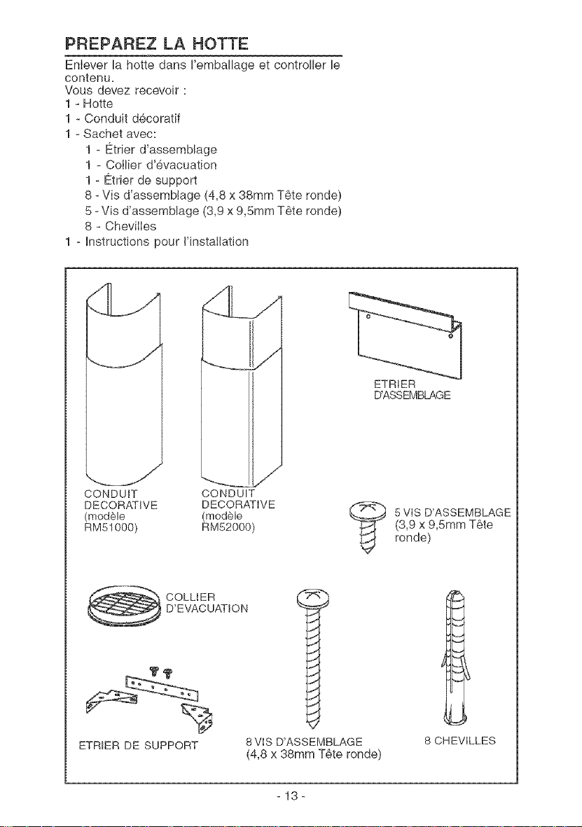
PREPAREZ LA HOTTE
Enlever la hotte dans I'emballage et controller le
contenu.
Vous devez recevoir :
1 - Hotte
1 - Conduit decoratif
1 - Sachet avec:
1 - E_trierd'assemblage
1 - Collier d'evacuation
1 - E_trierde support
8 - Vis d'assemblage (4,8 x 38ram T6te ronde)
5 - Vis d'assemblage (3,9 x 9,5ram T_te ronde)
8 - ChevilIes
1 - hstructions pour J'JnstaIJation
CONDUIT
DECORATIVE
(mod61e
RM51000)
J
CONDUIT
DECORATIVE
(mod_le
RM52000)
ETRtER
D'ASSEMBLAGE
5VIS D'ASSEMBLAGE
(3,9 x 9,5ram T6te
ronde)
COLLIER
D'EVACUATION
ETRIER DE SUPPORT
8VIS D'ASSEMBLAGE
(4,8 x 38ram T6te ronde)
8 CHEVILLES
-13-
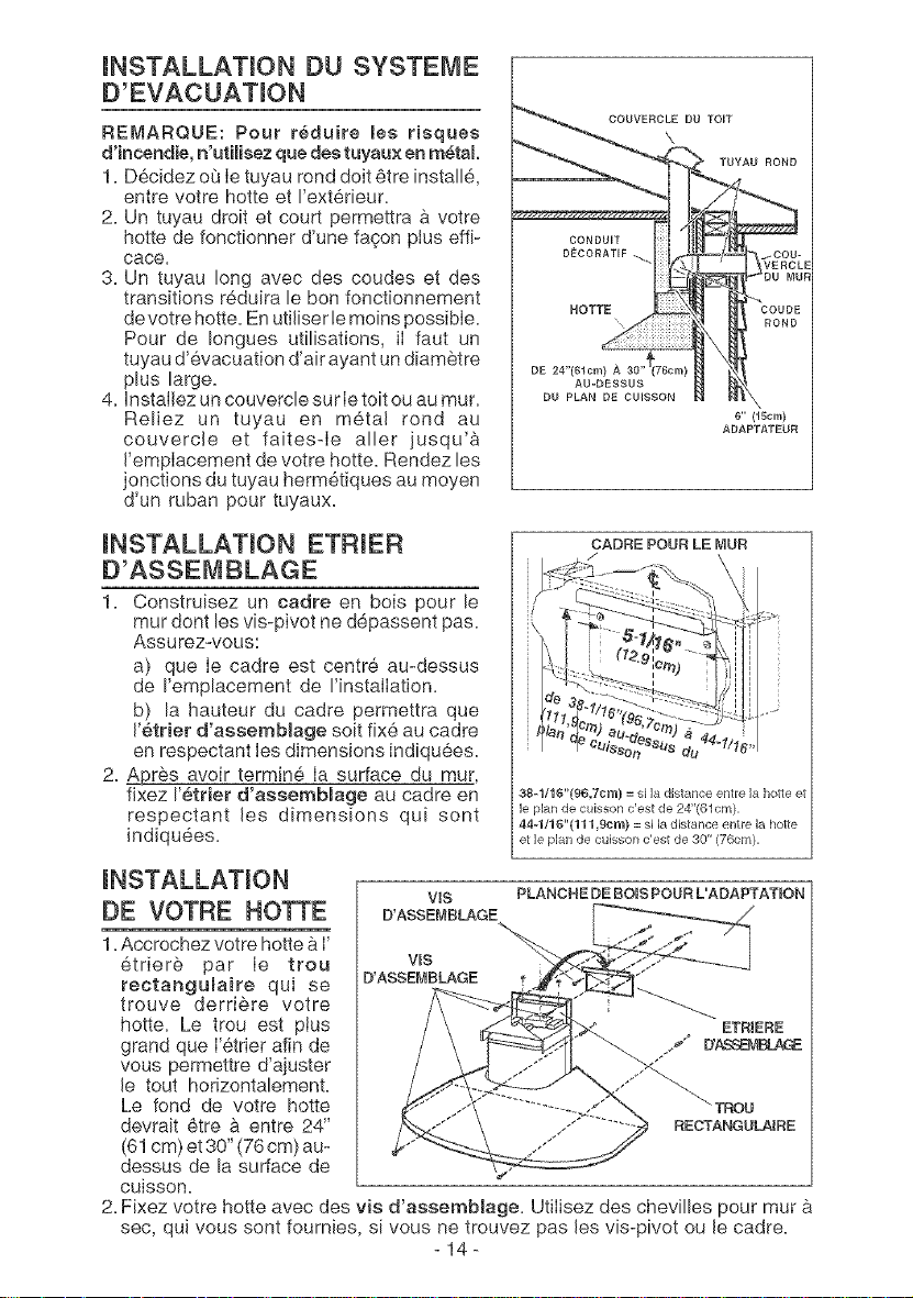
INSTALLATION DU SYSTEME
D'EVACUATION
RE[_ARQUE: Pour r_duire les risques
d'incendie, n'utiJisez que des tuyaux en m_tal.
1. D6cidez ou le tuyau rend dolt 6tre installe,
entre votre hotte et I'ext_rieur.
2. Un tuyau droit et court permettra & votre
hotte de fonctionner d'une fagon pius effi-
cace.
3. Un tuyau long avec des coudes et des
transitions reduira le bon fonctionnement
de votre hotte. En utiJiserlemoins possible.
Pour de Iongues utilisations, iI faut un
tuyau d'evacuation d'air ayant un diametre
plus large.
4. InstaJlez un couvercle sur Ietoit ou au mur.
Reliez un tuyau en metal rend au
couvercJe et faites-Ie aller jusqu'a
Femplacement de votre hotte. Rendez les
jonctions du tuyau herm6tiques au moyen
d'un ruban pour tuyaux.
INSTALLATION ETRIER
D'ASSEMBLAGE
1. Construisez un cadre en bois pour le
mur dent les vis-pivot ne depassent pas.
Assurez-vous:
a) que Ie cadre est centre au-dessus
de I'emplacement de I'instalIation.
b) la hauteur du cadre permettra que
Fetrier rf'assernblage soit fix6 au cadre
en respectant les dimensions indiqu6es.
2. Apres avoir termine Ia surface du tour,
fixez I'etrfer rf'assembmage au cadre en
respectant Jes dimensions qui sent
indiquees.
COUVERCLE DU TOIT
x
ROND
DE 24"(610m) A 30"
AU-DESSUS
DU PLAN DE CUISSON
6" (lScm)
ADAPTATEUR
CADRE POUR LE MUR
/,
38-1/16"(96,7Cm} = si la distance entre la hotte et
le plan de cuisson c'est de 24"(61cm).
44q/16"(111 gem) = si la distance entre la ho;le
et le plan de cuisson c'est de 30" (76cm).
WS
D'ASSEMBLAGE
PLANCHE DE BO_SPOUR L'ADAPTAT_ON
DE VOTRE HOT'rE
1. Accrochez votre hotte a I'
6triere par Ie trou ws
D'ASSEMBLAGE
rectangumaire qui se
trouve derriere votre
hotte= Le trou est plus ETRJERE
grand que I'6trier afin de [TA.%avl_
vous permettre d'ajuster
Je tout horizontalemenL
Le fond de votre hotte TROU
devrait 6tre & entre 24" RECTANGULAIRE
(61cm) et 30" (76 cm) au-
dessus de la surface de
CUiSSOr'L
2=Fixez votre hotte avec des vis rf'assemblage= Utilisez des chevilles pour tour a
sec, qui vous sont fournies, si vous ne trouvez pas Jesvis-pivot ou Jecadre.
14
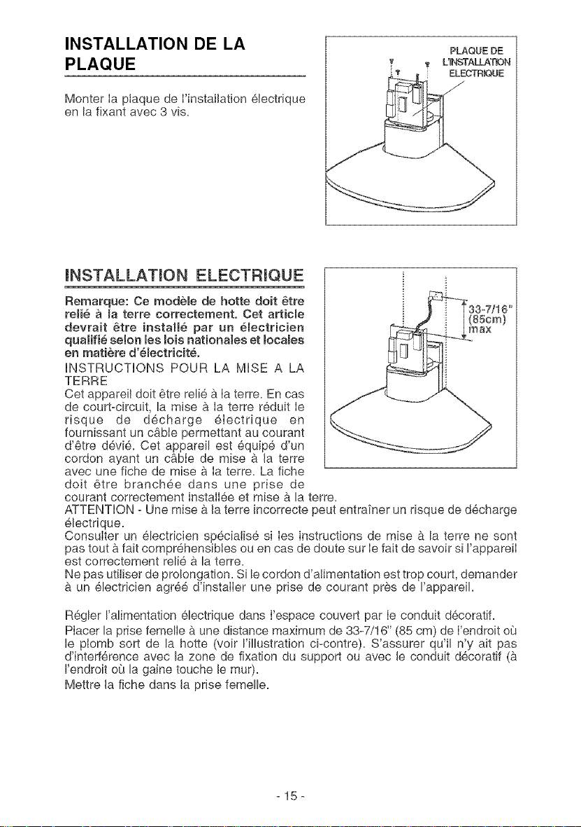
INSTALLATION DE LA
PLAQUE
Monter Ia piaque de I'installation 61ectrique
en la fixant avec 3 vis.
INSTALLATION ELECTRIQUE
Remarque: Ce modele de hotte doit _tre
reHe a _aterre correcternent. Cet articme
devrait _tre instaHe par un emectricien
qualifie selon Beslois nationales et locales
en matiere d'emectricite.
INSTRUCTIONS POUR LA MISE A LA
TERRE
Cet appareiI doit _tre relie a Ia terre. En cas
de court-circuit, la mise a Ia terre reduit Ie
risque de d_charge electrique en
foumissant un cable permettant au courant
d'etre devi6. Cet appareil est equipe d'un
cordon ayant un cable de mise a Ja terre
avec une fiche de raise a Ia terre. La fiche
doJt 6tre branchee dans une prise de
courant correctement instalIee et raise a la terre.
ATTENTION - Une mise a Jaterre Jncorrecte peut entrai'ner un risque de decharge
electrique.
Consulter un 61ectricien speciaiise si Ies instructions de raise a la terre ne sont
pas tout a fait comprehensibtes ou en cas de doute sur Ie fait de savoir s[ I'appareiI
est correctement relie a la terre.
Ne pas utiliser de prolongation. S[ le cordon d'aJimentation est trop court, demander
a un 61ectricien agre6 d'instalIer une prise de courant pres de I'appareik
Regler I'alimentation electrique dans I'espace couvert par Ie conduit d6coratif.
Placer la prise femelJe a une distance maximum de 33-7/16" (85 cm) de I'endroit oQ
le plomb sort de la hotte (volt I'illustration ci-contre). S'assurer qu'il n'y ait pas
d'intederence avec la zone de fixation du support ou avec Jeconduit decoratif (a
I'endroit oQ la gaine touche le mur).
Mettre Jafiche dans Ja prise femelle.
-15-
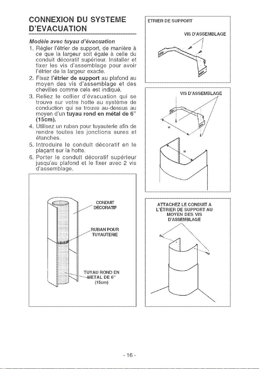
CONNEXION OU SYSTEME
D'EVACUATION
Modele avec tuyau d'evacuation
1. R6gler I'etrier de support, de maniere &
ce que la largeur soit egate a celle du
conduit decoratif sup@ieur, hstaller et
fixer Ies vis d'assemblage pour avoir
J'etrier de la Iargeur exacte.
2. Fixez I'etrier de support au plafond au
moyen des vis d'assemblage et des
chevilIes comme cela est indiqu6.
3. Retiez Ie collier d'evacuation qui se
trouve sur votre hotte au systeme de
conduction qui se trouve au-dessus au
moyen d'un tuyau rond en metam de 6"
(15cm).
4. Utilisez un ruban pour tuyauterie afin de
rendre toutes les jonctions sures et
etanches.
5. Hntroduire le conduit decoratif en le
plaqant sur Ia hotte.
6. Porter Ie conduit decoratif superieur
jusqu'au plafond et le fixer avec 2 vis
d'assemblage.
VJS D'ASSEMBLAGE
V_S D'ASSEMBLAGE
ATTACHEZ LE CONDUIT A
L'E_TRIER DE SUPPORT AU
MOYEN DES VlS
D'ASSEMBLAGE
-16-
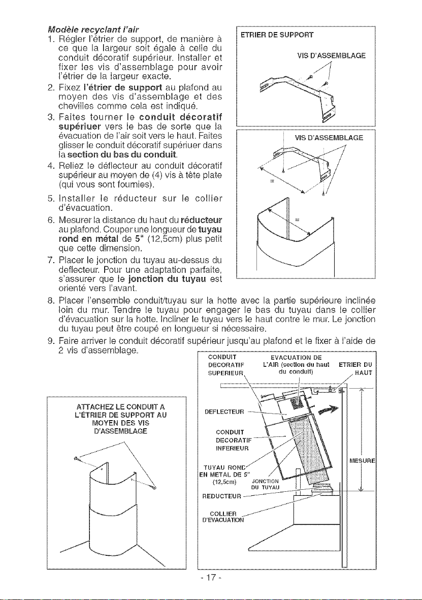
Modele recyclant Fair
1. R6gler I'etrier de support, de maniere a
ce que la largeur soit egale a celIe du
conduit decoratif sup@ieur, installer et
fixer Ies vis d'assemblage pour avoir
J'6trier de la Iargeur exacte.
2. Fixez I'etrier de support au plafond au
moyen des vis d'assembIage et des
cheviIles comme cela est indiqu6.
3. Faites tourner le conduit decoratif
supS.duet vers Ie bas de sorte que Ja
6vacuation de Fair soit vers le haul Faites
glisser le conduit d6coratif sup@iuer dans
Jasection du bas du conduit.
4. Reliez Ie defiecteur au conduit d6coratif
sup@ieur au moyen de (4) vis b.t_te plate
(qui vous sont fournies).
5. Installer Ie reducteur sur Je coJlier
d'evacuation.
6. Mesurer Iadistance du haut du reducteur
au plafond. Couper une Iongueur de tuyau
rond en metal de 5" (12,5cm) plus petit
que cette dimension.
7. Placer le jonction du tuyau au-dessus du
deflecteur. Pour une adaptation parfaJte,
s'assurer que Ie jonction du tuyau est
orient6 vers !'avant.
ETRIER DE SUPPORT
VIS D'ASSEMBLAGE
VIS D'ASSENBLAGE
8. Placer I'ensemble conduit/tuyau sur la hotte avec la partie sup@ieure inclinee
Join du mur. Tendre Ie tuyau pour engager le bas du tuyau dans Ie collier
d'evacuation sur la hotte. Incliner Ie tuyau vers Ie haut contre le tour. Le ionction
du tuyau peut @trecoupe en Iongueur si necessaire.
9. Faire arriver Jeconduit decoratif sup@ieur iusqu'au plafond et le fixer a I'aide de
2 vis d'assemblage.
CONDUIT EVACUATION DE
ATTACHEZ LE CONDUIT A
L'ETRIER DE SUPPORT AU
MOYEN DES VlS
D'ASSEMBLAGE
DECORATIF L'AIF{ (section du haut ETRIER DU
SUPERIEUR du conduit} / HAUT
CONDUIT _
DECORATIF V_
ENTUYAU_ALm_ENONCS,,JONC_ _,
,EDUC,EU,i Du_T_'u_l
COLHER j_
D'EVACUATION
17
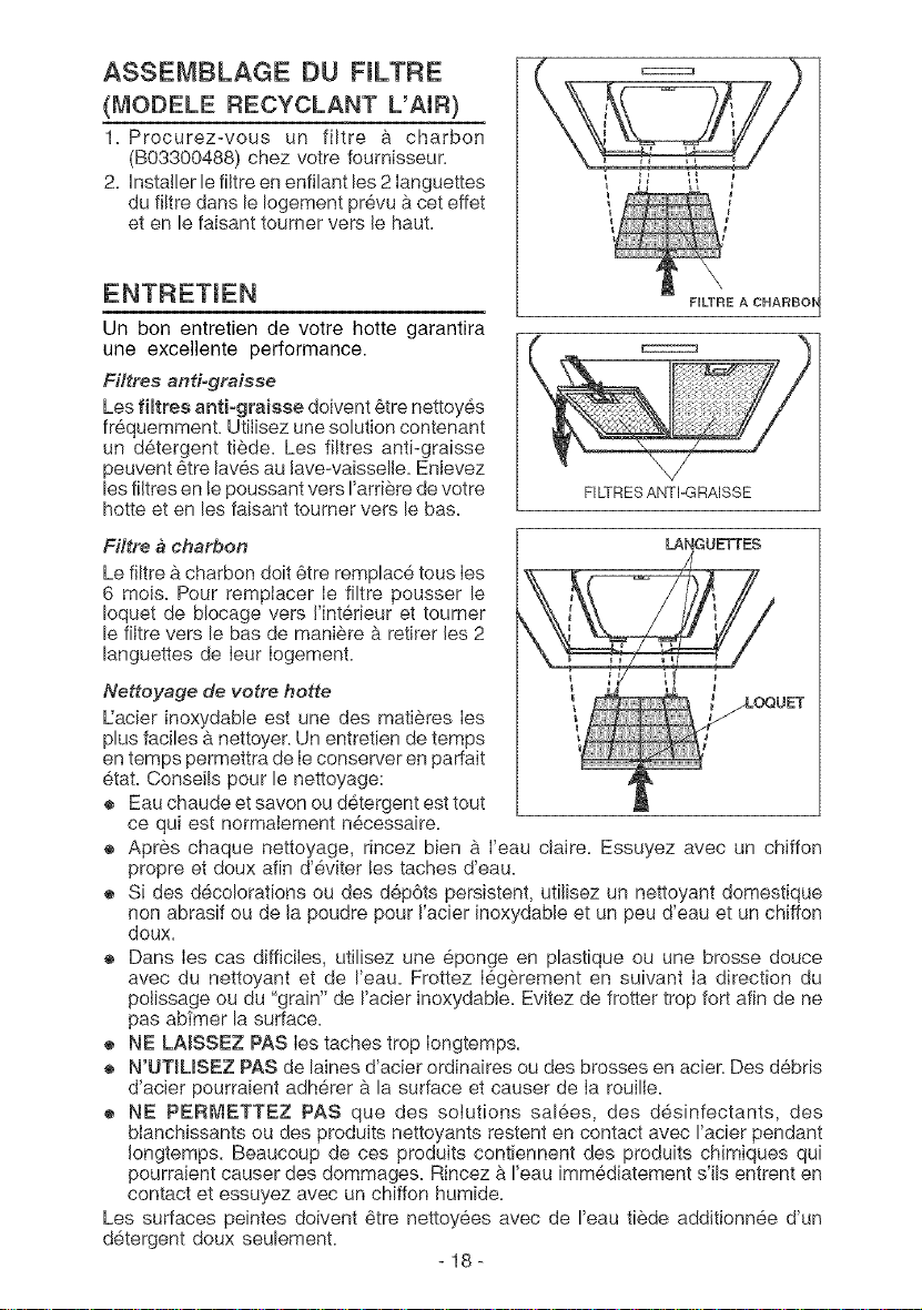
ASSEMBLAGE DU FILTRE
(MODELE RECYCLANT L'AR)
1. Procurez-vous un filtre & charbon
(B03300488) chez votre fournisseur.
2. Installer le filtre en enfilant les 2 Ianguettes
du filtre dans le Iogement prevu a cet effet
et en le faisant tourner vers Jehaul
Un bon entretien de votre hotte garantira
une excellente performance.
Filtres antiograisse
Les fiffres anti-graisse doivent _tre nettoyes
frequemment. UtiJisez une solution contenant
un detergent tiede. Les filtres anti-graisse
peuvent 6tre laves au Jave-vaisselle. Enlevez
les filtres en le poussant vers I'arriere de votre
hotte et en les faisant tourner vers le bas.
t
FILTRES ANTI-GRAISSE
Filtre a eharbon
Le filtre a charben dolt _tre remplace teus ies
6 mois. Pour rempJacer ie filtre pousser le
Ioquet de b!ocage vers I'interieur et toumer
le fiitre vet's le bas de maniere b,retirer Jes2
languettes de Ieur IogemenL
LANGUE'FTES
Nettoyage de votre hotte
L:acier inoxydable est une des matieres Ies
plus faciles a nettoyer. Un entretien de temps
en temps permettra de Ieconserver en parfait
etat. Conseils pour le nettoyage: _
® Eau chaude et savon ou detergent est tout
ce qui est normaIement n6cessaire.
® Apres chaque nettoyage, rincez bien _ I'eau claire. Essuyez avec un chiffon
propre et doux afin d'eviter les taches d'eau.
® S[ des decolorations ou des dep6ts persistent, utiJisez un nettoyant domestique
non abrasif ou de Japoudre pour J'acier Jnoxydable et un peu d'eau et un chiffon
doux.
® Dans Ies cas difficiles, utilisez une eponge en plastique ou une brosse douce
avec du nettoyant et de I'eau. Frottez Iegerement en suivant Ia direction du
polissage ou du "grain" de I'acier inoxydabJe. Evitez de frotter trop fort afin de ne
pas ab_mer la surface.
® NE LAISSEZ PAS Ies taches trop Iongtemps.
® N'UTJUSEZ PAS de laines d'acier ordinaires ou des brosses en acier. Des debris
d'acier pourraient adherer a la surface et causer de Ia rouille.
® NE PERMETTEZ PAS que des solutions salees, des desinfectants, des
btanchissants ou des produits nettoyants restent en contact avec I'acier pendant
Jongtemps. Beaucoup de ces produits contiennent des produits chimiques qui
pourraient causer des dommages. Rincez & I'eau imm6dJatement s'Jls entrent en
contact et essuyez avec un chiffon humide.
Les surfaces peintes doivent 6tre nettoyees avec de I'eau tiede addJtionnee d'un
detergent doux seulement.
-18-
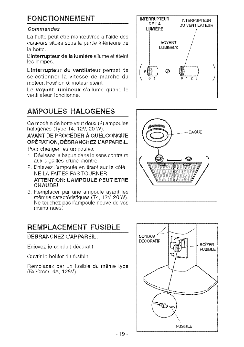
FONCTIONNEMENT
Commandes
La hotte peut 6tre manoeuvree & I'aide des
curseurs situes sous la partie inferieure de
la hotte=
L:interrupteur de la lumiere aiJume et eteint
les Jampes=
L'interrupteur du venti_ateur permet de
s_lectionner la vitesse de marche du
moteur= Position 0: moteur 6teint=
Le voyant lurnineux s'allume quand Je
ventiJateur fonctionne=
ENTERRUPTEUR INTERRUPTEUR
DE LA DU VENT_LATEUR
LUMP#RE
VOYANT
LUMINEUX
01 O 1 23
AMPOULES HALOGENES
Ce modele de hotte veut deux (2) ampoules
halogenes (Type T4, 12V, 20 W)=
AVANT DE PROCC:DER A QUELCONQUE
OPERATION, DC:BRANCHEZ L'APPAREIL
Pour changer Ies ampoules:
1= Devissez la bague dans Ie sens contraire
aux aiguilIes d'une montre=
2= Enlevez I'ampoule en tirant sur le c6te
NE LA FAITES PAS TOURNER
ATTENTION: L'AMPOULE PEUT ETRE
CHAUDE!
3= Remplacer par une ampouIe ayant Ies
m6mes caracteristJques (T4, 12V, 20 W)=
Ne touchez pas J'ampoule neuve de vos
mains nues!
REMPLACEMENT FUSIBLE
DC:BRANCHEZ L'APPAREIL
Enievez ie conduit decoratif=
Ouvrir le boi'tier du fusible=
Remplacez par un fusible du re@me type
(5x20mm, 4A, 125V)=
DECORATIF
19
FUSIBLE
GARANTIE
GARANTIE BROAN-NUTONE LLC LIMITEE A UN AN
Broan-Nu[bne LLC garantit au consommateuPacheteu rde ses prt'xJLIJtsq ue OeSproduits seront sans d'5__./uts concernant les
mati8 res employ_es et concemant la fabrication pendant/_ne p_dode d'un an _ partir de la date d'achat. IL N'Y A AUC UNE
AUTRE GARANTIE, EXPLICITE OU IMPLICITE,Y COMPRIS, MAIS NON PAS LIMITEE A, LES GARANTIES IMPLICITES
OU CONCERNANT LA CAPACITE COMMERCIALE OU LA CONVENANCE POUR TOUT BUT PARTICULIER Pendant
cette p_dode d'un an, Broan-N/l[i)l/e L LC r6pare ra ou remplacera, s'Hle jugera n6cessaire, grah_iternent, tout article ou to/_te
pi_.cequi resulteront d_fectueux _ condition qu'ils aient _t6 utilis_e et entretenu correcterhent.
CETTE GARANTIE NE S'ETEND PAS AUX INTERRUPTEURS DES NEON. NEON. LAMPES HALOGENES. AMPOULES
d"ILLBMINAqION. Cette garantie ne couvre pas (a) Fentretien normal ni {b) tout article ou toute piece q_i aient subi une
utilisation erron_e, une n6gligence, un accident, un entretien e rron6 ou une reparation (autre que de la part de Broan-NuR/ne
LLC), une installation d_fectueuse ou bien une installation ne respectant pas les instructions d'installation recommand6es. La
dur_e de toute garantie irnplicite est lirnit6e a un an cornme cela est sp6cifi&, dans la garantie explicite. Quelques 6tats ne
permettent pas de lirhites quant {_la du tee d'une garantie implicite, par cons6quent la limitation indiqu6e ci-dessus peut ne pas
vous concemer
L'OBLIGA_ ION DE REPARER OU DE REMPLACER DE LA PAR]- DE BROAN-NUTONE LLC SERA LE SEUL ET EXCLUSIF
REMEDE DE L'ACHETEUR COUVERT PAR CETTE GARANTIE. BROAN-NUTONE LLC NE SERA PAS RESPONSABLE
DES DOMMAGES ACCIDENTELS. CONSEQUENTIELS OU SPECIAUX DUS A L'UTILISARON DU PRODBIT OU A SA
PERFORMANCE OU EN ETANT LA CONSEQU ENCE. Quelques 6t_ts ne permellent pas I'exclusk)n o_ la limitation des
dornrnages accidentels ou cons&.quentiNs, par cons6q uent la IJrnit;_tionindiqu_e ci-dessus peut ne pas vous conce rner.
Cette gar:lrMe vous donne des droits I_gaux sp6ciflques, et vous pouvez ausN avoir d'a_tres d roits, <:luivarient d'Etat _ Etat.
Cette gartlntie d6passe route garantie prec6dente. R)ur avoir droit _ la garantie, w)us devez (a) avertir la Maison Br_>amNulT)ne
LLC a Fadresse indiqu6e ci-dessous ou t_16phoner : 1-800-637-1453, (b) donner le num_ro du module et Fidentification de la
pi6ce d_fect_euse et (c) d_crire la n_._ture de tout d_faut de Fartide ou de la pi_.ce. Au moment oLi vous dernandez le service
de garantie, v(:l_s devez presenter la preuve d'achat avec la date.
B_'oan-NuTone LLC. 926 West State Street, Ha rtford, W153027 (1-800-637-1453)
NuTone, inc., 4820 Red Bank Road. Cincin nati, OH 45227 {1-800-543-8687)
B_'oan-NuTone Canada, inc. 1140Tristar Drive, Mississauga, Ontark), L5T 1H9 {1-888-882-7626)
- 20 -
INDICADOPARAELUSOENCOCINAS
DOMESTICAS.
PARA EVlTAR EL RIESGO DE iNCENDIO,
CORTOCIRCUITO O DAI_O PARA LAS
PERSONAS, OBSERVE ATENTAMENTE LAS
SIGUIENTES NORMAS:
1. Use esta unidadsolamente de lamanera indicadapor
elfabricante; sitiene dudas, p6ngase encontacto con
@tea la direcci6n otel6fono indicados en la garant[a.
2. Antes de hacer una revisi6n o de limpiar la unidad,
descon@tela dela red paraevitarquese enciendade
maneraaccidental.En elcasodeque@tenopuedaser
desactiovado,seindicar_enlaplacadecaracteoristicas.
3. El montaje y la instalaci6n el@trica debe hacerlos un
t@nicoespecializadosiguiendolas normasest_ndar e
induyendo aquellasdeconstrucci6n antiincendio.
4. Necesitaairesuficienteparaunaapropiadacombusti6n
y escape de gases a trav6s deltubo del dep6sito de
quemadecombustible.Paraevitarqueelhumoaspirado
vuelva a la cocina, siga las directivas delfabricante y
lasnormas est_ndardesiguridadasfcomo lasnormas
puMicadasporlaAsociaci6ndeprevenci6ndeincendios
(NFPA)ylaSocieodadamericana deespecialistas en
caleofacci6n,refrigeraci6ny aireacondicionadoyademas
lasnormas delas autoridadeslocales.
5. Hacer uncorte ountabdro en laparedoen eltecho no
debeda_arla instalaci6nel@tricauotrasinstalaciones
ocultasen la pared.
6. Losconductosventiladoresdeben siempredesalojaral
exterior.
7. No use esta unidad con dispositivo de control de la
velocidadaestado s61ido.
8. Para evitar el riesgo de incendio, use solamente
conductos demetal.
9. Esta unidadtiene queserconectada atierra.
PARA EVITAR EL RIESGO DE FUEGO POR ALTO
NIVEL DE GRASA:
A. Nuncaabandone losquemadores con elfuego alto.
Lacccci6n causahumoy restosdegrasa quepueden
arder. Caliente elaceite afuego medio obajo.
B. Endendasiemprelacampanacuandococineafuego
alto o cuando cocine alimentos facilmente
inflamables.
C. Limpiecon frecuencia los ventiladores. Nose debe
acu mulargrasa enelventilador o enel filtro.
D. Usa eltama_p de cazuela apropiado. Use siempre
utensiliosdecocinadetamaF_oymaterialadecuados.
PARA EVlTAR EL RIESGO DE DANOS A
PERSONAS EN CASO DE FUEGO POR ALTO
NIVEL DE GRASA, TENGA EN CUENTA LO
SIGUIENTE:*
1.SOFOQUE LALLAMAcon unatapaderaapropiada,una
bandeja metbJica6un utensilio decoc[na qu.epueda
cubrirla,despues, @ague el quemador.ACTUECON
PRECAUCION PARAEVlTARQUEMAoDURAS.Si la
llamanose extingueinmediaotamente,SALGAYLLAME
A LOSBOMBE-ROS.
2.NUNCACOJA UNASARTEN ENLLAMAS, porquecorre
elriesgo dequemarse.
3.NO USEAGUA nipa_osotoallas hOmidasporquepuede
provocarseunaviobnta humareda.
4.Use unextintor SOLAMENTE si:
A. Posee un extintor de clase ABC y sabe
perfectamentec6mo usarlo.
B. EIfuegoes pequdioyest_ controbdoenel mismo
sitio enque empez6.
C. HaIlamadocon anterioridadalos bomberos.
D. Puede combatir elfuego retrocediendo hacia la
salida.
*Basadoen"Seguridadantifuegoenlaccc[na"publicado
porNFPA.
8,
9.
-21 -
ADVERTENCIA
1. Para reducir el riesgo de incendios y para evacuar
correctamenteloshumos,asegurarsedehaberrealizado
unaconducci6n del airehasta elexterior. Noexpulsar
loshumosen espacios cerradospot paredesotechos,
aticos,espacios angostos o garajes.
2. Prestar la m_xima atenci6n al utilizar productos de
limpiezaodetergentes.
3. Evitar el uso de productos alimentarios que puedan
inflamarsebajola campana.
4. S61opara ventilaci6n total. No use gases de escape
peligrososo materialesy vapores explosivos.
5. Para evitar daFlosen el funcionamiento del motor e
impulsores ruidosos y/o desequi librados, mantenga
alejadesde la unidadde encendido pulverizadoresen
secoo polvo.
6. Elmotortiene unniveldesobrecargat@micaque apaga
automaticamente el motor cuando se ha recalentado
excesivamente. El motor se pone de nuevo en
fincionamento cuando latemperatura baja. Siel motor
comienza aencenderse y a apagarse, deberb_hacer
unarevisi6nde 6ste.
7. Para limpiar mejor las impurezas al cocinar, la parte
inferior de la campana debe estar aunatemperatura
minimade24gradosy mb_ximade30gradosperdebajo
delatemperature de la zona decocci6n.
Debido asu gran tamale y peso, se recomienda su
montajepor partededos t@nicos esperializados.
Se recomienda leer la placa de caracteoristicas del
produdo para ulteriorinformaci6n.
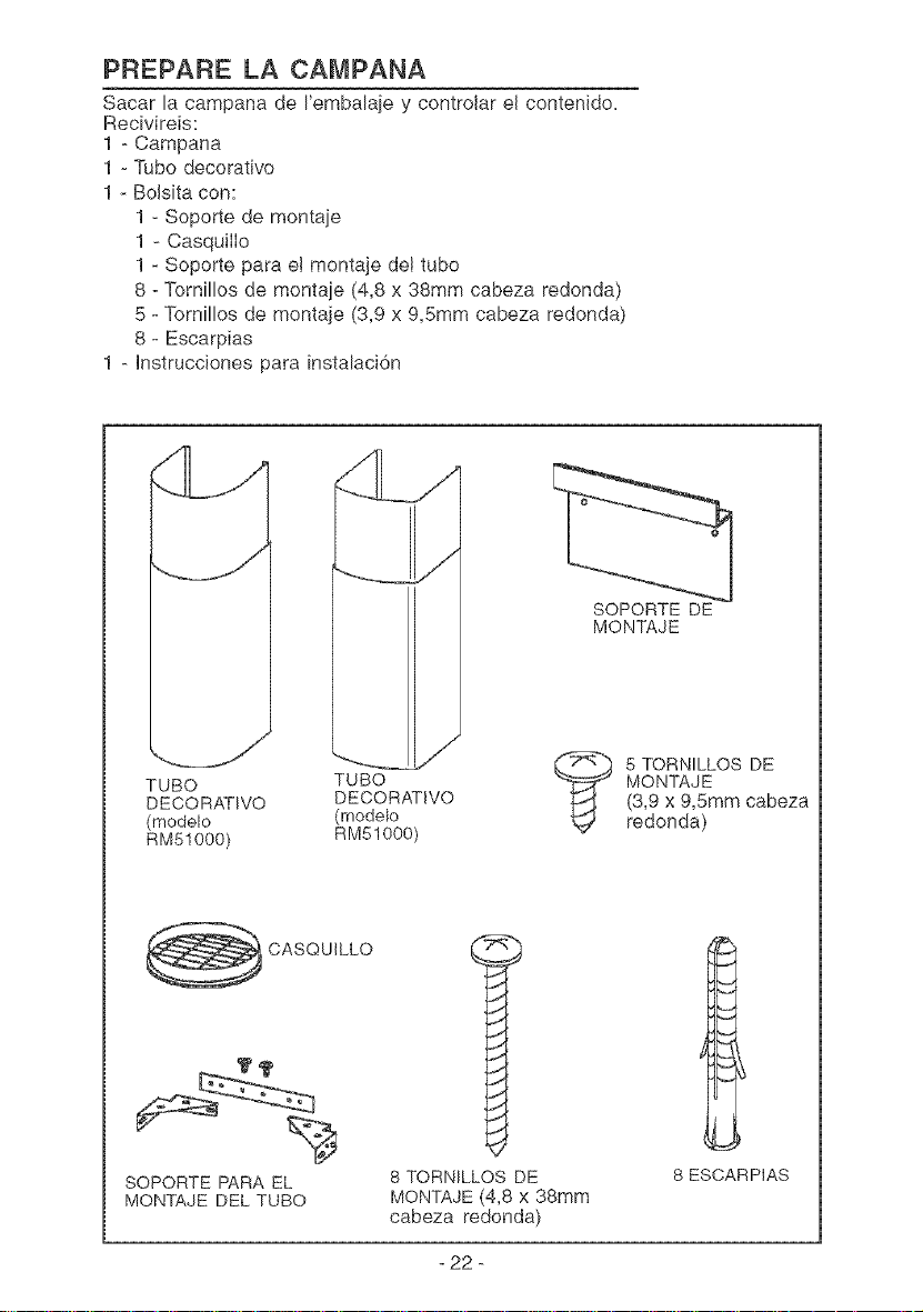
PREPARE LA CAMPANA
Sacar la campana de I'embalaje y controlar el contenido.
Recivireis:
1 - Campana
1 - Tubo decorativo
1 - Bolsita con:
1 - Soporte de montaje
1 - CasquilIo
1 - Soporte para e! montaje de! tubo
8 - Tornillos de montaje (4,8 x 38mm cabeza redonda)
5 - Tornillos de montaje (3,9 x 9,5ram cabeza redonda)
8 - Escarpias
1 - Instrucciones para instalaci6n
SOPORTE DE
MONTAJE
,.j/
TUBO
DECORATIVO
(modelo
RM51000)
TUBO
DECORATWO
(modelo
RM51000)
5 TORNILLOS DE
MONTAJE
(3,9 x 9,5ram cabeza
redonda)
CASQUILLO
SOPORTE PARA EL
MONTAJE DEL TUBO
8 TORNILLOS DE
MONTAJE (4,8 x 38ram
cabeza redonda)
8 ESCARPIAS
- 22 -
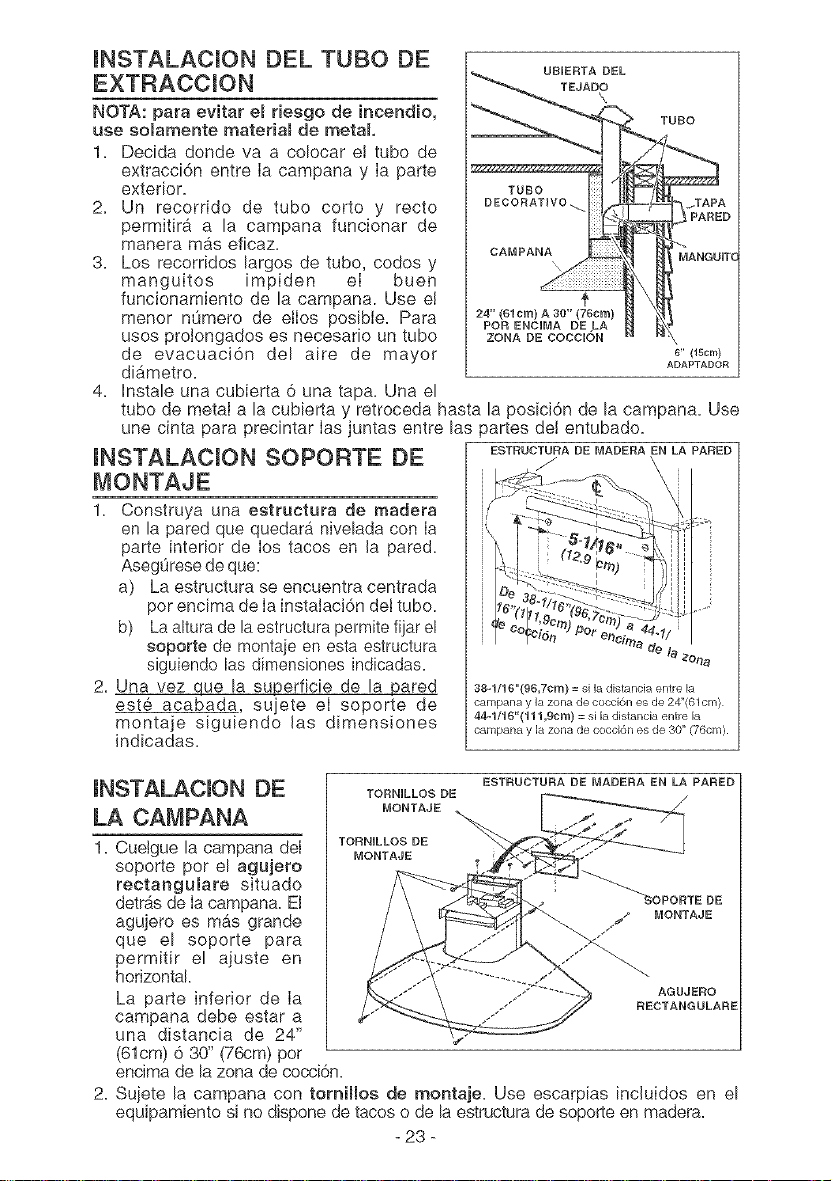
mNSTALACION DEL TUBe DE
EXTRACCION
NOTA: para evitar el riesge de incendio,
use seiamente material de metal
1. Decida donde va a colocar e! tube de
extracci6n entre Ia campana y Ia parte
exterior.
2. Un recorrido de tubo corto y recto
permitira a la campana funcionar de
manera mAs eficaz.
3. Los recorridos largos de tube, codes y
manguitos impiden eI buen
funcionamiento de la campana. Use e!
menor nOmero de ellos posible. Para
uses prolongados es necesario un tube
de evacuaci6n del aire de mayor
diAmetro.
4. Instale una cubierta 6 una tapa. Una el
URIERTA DEL
TEJADO
\
TURO
6" (15cm)
ADAPTADOR
tubo de metal a la cubierta y retroceda hasta la posici6n de la campana. Use
une cinta para precintar Ias juntas entre las partes del entubado.
mNSTALACmON SOPORTE DE ESTRODTO.A/ DE MADERA EN LA PARED
MONTAJE
1. Construya una estructura de madera
en la pared que quedara nivelada con Ia
parte interior de Ios tacos en la pared=
AsegOrese de que:
a) La estructura se encuentra centrada
per encima de Ia instalaci6n det tubo.
b) La altura de la estructura permite fijar el
soporte de montaje en esta estructura /_zone
siguiendo las dimensiones indicadas.
2. Una vez que la superficie de la pared 38q/16"(96,7cm)=siladistanciaentrela
este acabada sujete eI soporte de carnpanaylazonadecocci6nesde24"(61cm)
44q/16"(111,9cm) = si la distancia entre la
montaje siguiendo las dimensiones
campana y la zona de cocci6n es de 30" (76cm).
indicadas.
mNSTALACION DE
LA CAMPANA
TORNILLOS DE
MONTAJE
TORNILLOS DE
MONTAJE
ESTRUCTURA DE MADERA EN LA PARED
- 23 -
1. Cuelgue la campana deI
soporte per el agujero
rectangulare situado
detr_s de Iacampana. El DE
_ MONTAJE
agujero es m&s grande
j_
que el soporte para
permitir el ajuste en
horizontal.
La parte inferior de Ia AGUJE_O
RECTANGULARE
campana debe estar a
una distancia de 24"
(61cm) 6 30" (76cm) pot
encima de la zona de cocci6n.
2. Suiete la campana con tomiHos de montaje. Use escarpias incluidos en el
equipamiento si no dispone de tacos o de la estructura de soporte en madera.
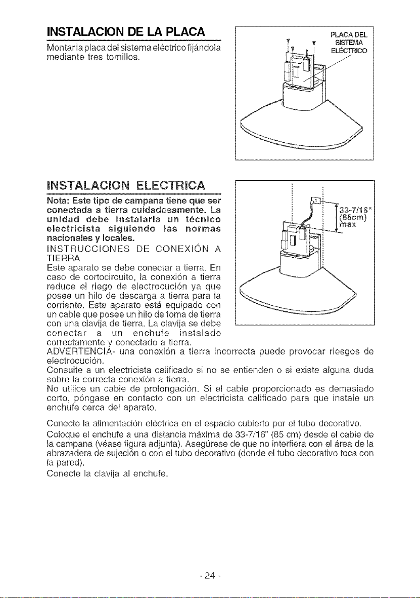
INSTALACION DE LA PLACA
Montar Iaplaca deI sistema electrico fij_ndoJa
mediante tres tornillos.
PLACA DEL
_ S_STEMA
i ELECTR_O
INSTALACION ELECTRICA
Nota: Este tipo de campana tiene que set
conectada a tierra cuidadosamenteo La
unidad debe inetamarla un tecnico
electricista siguiendo mas norrnas
nacionalee y locales,
INSTRUCCIONES DE CONEXION A
TERRA
Este aparato se debe conectar a tierra. En
caso de cortocircuito, la conexi6n a tierra
reduce eI riego de electrocuci6n ya que
posee un hilo de descarga a tierra para Ia
corriente. Este aparato est_ equipado con
un cable que posee un hilo de toma de tJerra
con una clavija de tierra. La clavija se debe
conectar a un enchufe instalado
correctamente y conectado a tierra.
ADVERTENCIA- una conexi6n a tierra incorrecta puede provocar riesgos de
electrocuci6n.
ConsuIte a un electricista calificado si no se entienden o sJ existe alguna duda
sobre Ia correcta conexi6n a tJerra.
No utilice un cabIe de prolongaci6n. Si et cabIe proporcionado es demasJado
corto, p6ngase en contacto con un electricista calificado para que instale un
enchufe cerca del aparato.
Conecte la alimentaci6n electrica en et espacio cubierto per el tubo decoratJvo.
Coloque el enchufe a una distancia m4xima de 33-7/16" (85 cm) desde e! cable de
la campana (vease figura adjunta). Aseg0rese de que no interfiera con el &rea de la
abrazadera de suieci6n o con el tube decorative (donde el tube decorative toca con
la pared).
Conecte la clavija al enchufe.
24
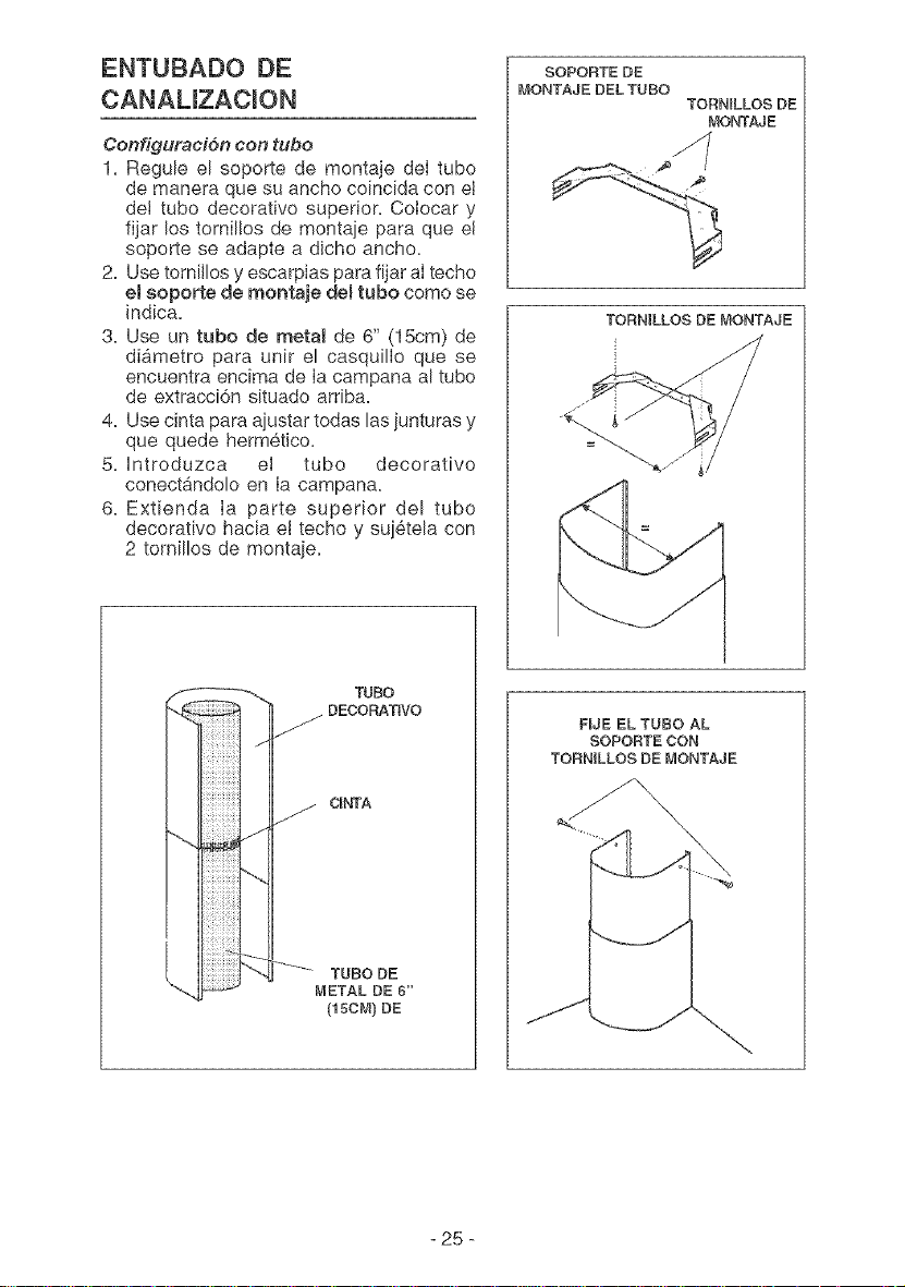
ENTUBADO DE
CANAUZACmON
Conf!guraci6n con tubo
1. Regule el soporte de montaje del tube
de manera que su ancho coincida con el
de! tubo decorativo superior. CoIocar y
fijar los tornillos de montaje para que el
soporte se adapte a dicho ancho.
2. Use tornillos y escarpias para fijar aItecho
eI soporte de montaje demtubo come se
indica.
3, Use un tube de metal de 6" (15cm) de
di_metro para unit el casquillo que se
encuentra encima de Ia campana al tube
de extracci6n situado arriba.
4. Use cinta para ajustar todas las junturas y
que quede hermetico.
5. Introduzca eI tubo decorative
conectAndolo en Ia campana.
6. Extienda Ia parte superior del tube
decorativo hacia e! techo y suj6tela con
2 tornillos de montaje.
SOPORTE DE
MONTAJE [}EL TUBO
TORNILLOS DE
MONTAJE
TORNILLOS DE MONTAJE
TUBO
DECORATIVO
CINTA
TUBO DE
METAL DE 6"
(15cM)DE
F_JE EL TUBO AL
SOPORTE CON
TORNILLOS DE MONTAJE
- 25 -
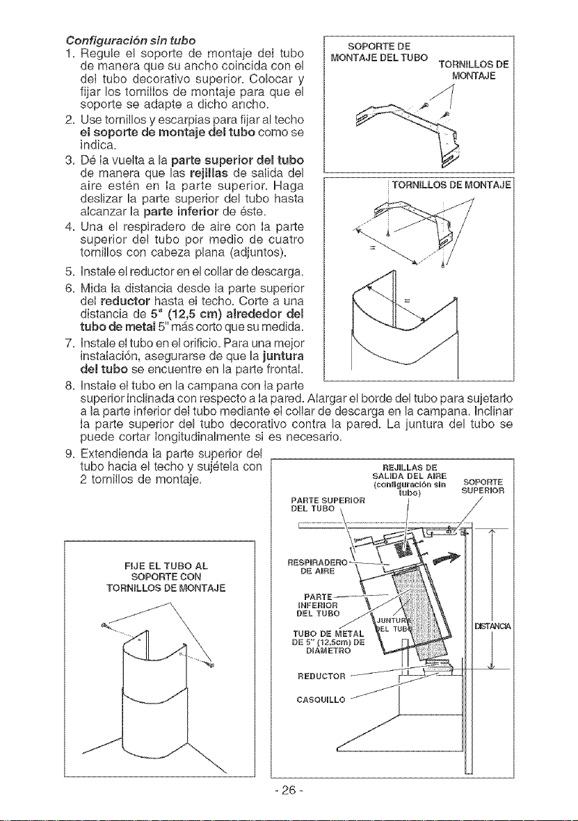
Configuraci6n sin tubo
1. Regule el soporte de montaje deI tube
de manera que su ancho coincida con el
deI tubo decorative superior. Co!ocar y
fijar los tomilIos de montaje para que el
soporte se adapte a dicho ancho.
2. Use tornillos y escarpias para fijar al techo
el soporte de montaje del tube come se
indica.
3. De Ia vuelta a la parte superior del tubo
de manera que las rejilas de salida del
aire esten en Ia parte superior. Haga
deslizar la parte superior del tube hasta
aIcanzar la parte inferior de este.
4. Una el respiradero de aire con Ia parte
superior det tubo per medio de cuatro
tornillos con cabeza plana (adjuntos).
5. Instale e! reductor en el collar de descarga.
6. Mida Ia distancia desde Ia parte superior
deI reductor hasta el techo. Corte a una
distancia de 5" (12,5 cm) a_rededor del
tubo de metal 5" m&scorte que su medida.
7. Instale el tube en el orificio. Para una mejor
instaiaci6n, asegurarse de que la juntura
demtubo se encuentre en la parte frontal.
8. Instale et tube en la campana con Ia parte
SOPORTE DE
MONTAJE DEL TUBO
TORNtLLOS DE
MONTAJE
TORNILLOS DE MONTAJE
superior inclinada con respecto a Ia pared. Alargar el borde de! tubo para sujetarIo
a la parte inferior del tube mediante el collar de descarga en la campana. Inclinar
Ia parte superior del tube decorative contra la pared. La iuntura del tubo se
puede cortar Iongitudinalmente si es necesario.
9. Extendienda Ia parte superior det
tube hacia el techo y sujetela con REJULLASDE
2 tornilIos de montaie.
FUE EL TUBO AL
SOPORTE CON
TORNILLOS DE MONTAJE
- 26 -
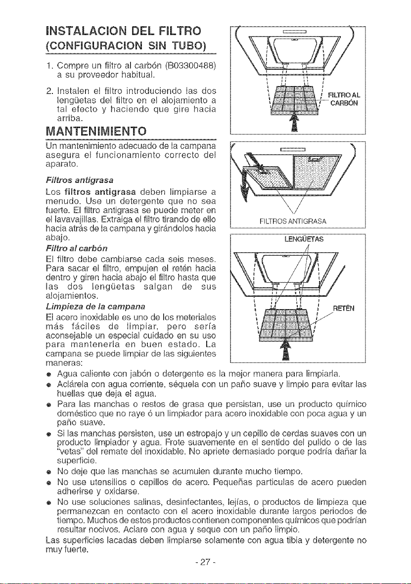
mNSTALACmON DEL FJLTRO
(CONFJGURACJON SIN TUBO)
1. Compre un filtro al carb6n (B03300488)
a su proveedor habitual.
2. Instalen el filtro Jntroduciendo Ias dos
JengOetas del filtro en el alojam[ento a
tal efecto y haciendo que gire hacia
arriba.
MANTENJMJENTO
Un mantenlmiento adecuado de Ia campana
asegura el funcionamlento correcto deJ
aparato.
Fi#ros antigrasa
Los fimtroe antigrasa deben limplarse a
menudo. Use un detergente que no sea
fuerte. El filtro antigrasa se puede meter en
el Iavava]JlJas.Extraiga el filtro tlrando de etlo
hacia atr&s de Iacampana y gir#_ndoloshacia
abajo.
Filtro M carb6n
E! filtro debe cambiarse cada seis meses.
Para sacar el filtro, empu]en el reten hacia
dentro y giren hacia abajo eJfiltro hasta que
las dos lengQetas salgan de sus
aIojamientos.
Mmpieza de la campana
El acero inoxidable es uno de los meteriaJes
m&s f&cJles de Iimpiar, pero ser[a
aconsejable un especiaI cuidado en su uso
para mantenerJa en buen estado. La
campana se puede Iimpiar de Jassiguientes
maneras:
® Agua caJiente con ]ab6n o detergente es
® Act&rela con agua corriente, sequela con
hueIlas que de]a eI agua.
RLTROAL
FILTROS ANTIGRASA
LENGOETAS
la mejor manera para Iimpiada.
un patio suave y limpio para evitar las
- 27 -
® Para las manchas o restos de grasa que persistan, use un producto quimico
domestico que no raye 6 un limpJador para acero inoxidable con poca agua y un
patio suave.
® S[ las manchas persisten, use un estropajo y un cepil!o de cerdas suaves con un
producto limpiador y agua. Frote suavemente en el sentido del puJido o de las
"vetas" del remate del inoxidable. No apriete demasiado porque podr[a datiar la
superficie.
® No de]e que las manchas se acumuJen durante mucho tiempo.
® No use utensilJos o cepilJos de acero. Pequetias particulas de acero pueden
adherirse y oxidarse.
® No use soluciones salinas, desinfectantes, Iejias, o productos de Iimpieza que
permanezcan en contacto con el acero inoxidable durante largos periodos de
tiempo. Muchos de estos productos contienen componentes qu[micos que podr[an
resultar nocivos. AcIare con agua y seque con un patio Iimpio.
Las superficies Jacadas deben limpiarse soJamente con agua tibia y detergente no
muy fuerte.
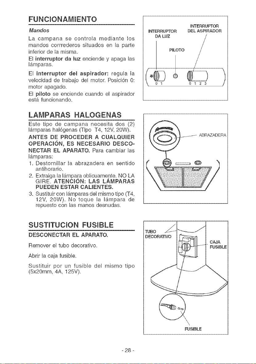
FUNCmONAMIENTO
Mandos
La campana se controla mediante Ios
mandos corrrederos situados en la parte
inferior de Ia misma.
El interruptor da luz enciende y apaga las
I_mparas.
El interruptor del aspirader: regula Ia
velocidad de trabajo del motor= Posici6n O:
motor apagado,
El piloto se enciende cuando el aspirador
estA funcionando,
LAMPARAS HALOGENAS
Este tipo de campana necesita dos (2)
I&mparas hal6genas (Tipo T4, 12V, 20W).
ANTES DE PROCEDER A CUALQUIER
OPERACK3N, ES NECESARIO DESCO-
NECTAR EL APARATO. Para cambiar las
IAmparas:
1_ Destornillar Ia abrazadera en sentido
antihorario.
2_ Extraiga la I&mpara oblicuamepte. NO LA
GRE. ATENCION: LAS LAMPARAS
PUEDEN ESTAR CAUENTES.
3. Sustituir con I&mparas del mismo tipo (T4,
12V, 20W). No toque la I&mpara de
repuesto con las manos desnudas.
_NTERRUPTOR
ENTERRUPTOR DEL ASPERADOR
DA LUZ
P_LOTO
/
, i
°©
01 0123
)
ABR#ZADERA
SUSTmTUCmON FUSIBLE
DESCONECTAR EL APARATO.
Remover el tubo decorativo.
Abrir Ia caja fusible.
Sustituir pot un fusible del mismo tipo
(5x20mm, 4A, 125V).
_RJBO
DECORATIVO
\,
FUSEBLE
- 28 -
GARANTIA
GABANTIA BBOAN-NBTONE LLC PON UN Al_O
Broan-Nul_ne LLC garantiza al consumidor-cornprador de sus productos que dichos productos no tendmn detectos en los
matedales o fabricaci6n, durante un perk)do de _n ano a psrtir de la fecha de la compra. NO HAY OTBO TIPO DE
GARANTIAS QUE INCLUY/_,N O SE LIMITEN EXCLUSh/AMENTE A GARANTIAS IMPLICFI-AS O DE CAPACIDAD
COMERCIAL O CONVE-NIENCIA PARA UN PROPOSITO ESPECIFICO.
Durante el period() de un af/o, Broan-NuR}ne LLC, si [o estirna conveNente, reparar& o reemplazara sin gastos pars 8[
usuario cualquier prod/_cto (7parte de @stegue sea defectuosos haN6n_!ose usado correclamente, ESTA GABANTIA NO
CUBRE: ESTARTER DE NEON, NEON, LAMPARAS HALOGENAS, LAMPARAB DE ILUMINACION, "Rarnpoco cubre el
mantenJmiento ni los prod_ctos o psrtes de 6stos que hayan sJdo usados de forms Jncorrecta, con neglJgenNa, rotos
accidentak_ente o pot una incorrecta rnsnutenci6n 6 reparaci6n (distinta da la realizads pot BroamNdl-one LLC), montaje
incorrecte 6 instalaN6n que no se a}uste s las instrucNones de montaje indicadss. Le duraci6n de la garantia se lirnita al
periodo de tin ano corno est_ especMcado en la garantia explicita. Algunos paises no perrcliten un IJmiteen la duraci6n de
la garantia impliNta; si es aN en su caso, esta limitaN6n arriba Jndicada podda no aplicarse. LA PRESENTE GABANTIA
CUBRIRA EXCLUSIVAMENTE AL COMPRADOR LOS SERVICIOS DESCRITOS ANTERIORMENTE. BROAN-
NUTONE LLC NO SE HACE RESPONSABLE DE DANOS PBODUCIDOS DE MANERA ACCIDENTAL O
RELACIONADOS CON EL USO INCORRECTO DEL PRODUCTO O SU FUNCIONAMIENTO. Algunos paises no
perrNten la excl/_si6n o IJmitaci6n de los dailos producidos de rnanera accidental, si es asi en su caso, esta IJrhitaN6n arriba
indicada podda no aplJcsrse. Esta garant in le da derechos legales especificos y podria tarnbi6n disponer de ot rosderechos
que varian de pais a pais. Esta garantia supers otras garantias dadas con anterioridad Pars dJsfrutar de la garantia usted
deber4 a) Avisar a la direcN6n abajo indicada 6 bien Ilamar pot telSfono al n/imero 1-800-637-1453 b) Dar el numero de
sede del modelo eorrespondiente o bien una descripci6n de la parte averiada, c) Descripci6n del defecto en el produclo o
bien en una de sus pades, Pars requerir un serviNo en garantia delle presentar el justificante con la fecha de la corrlpra.
B_'oan-NuTone LLC. 926 West State Street, Hartford, W153027 (1-800-637-1453)
NuTone, Inc. 4820 Red Bank Road, Cincin nail OH 45227 (1-800-543-8687)
B_'oan-NuTone Canada, Inc. 1140Tristar Drive, Mississauga, Ontario, L5T 1H9 {1-888-882-7626)
29
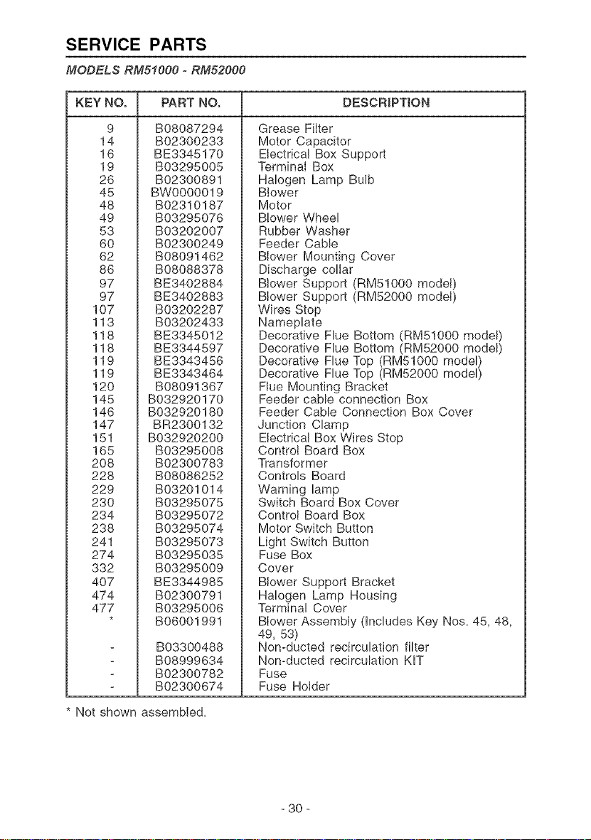
SERVICE PARTS
MODELS RM51000 =RM52000
KEY NO. PART NO, DESCRiPTiON
9
14
16
19
26
45
48
49
53
6O
62
86
97
97
107
113
118
118
119
119
120
145
146
147
151
165
2O8
228
229
230
234
238
241
274
332
4O7
474
477
B08087294
B02300233
BE3345170
B03295005
B02300891
BW0000019
B02310187
B03295076
B03202007
B02300249
B08091462
B08088378
BE3402884
BE3402883
B03202287
B03202433
BE3345012
BE3344597
BE3343456
BE3343464
B08091367
B032920170
B032920180
BR2300132
B032920200
B03295008
B02300783
B08086252
B03201014
B03295075
B03295072
B03295074
B03295073
B03295035
B03295009
BE3344985
B02300791
B03295006
B06001991
B03300488
B08999634
B02300782
B02300674
Grease Filter
Motor Capacitor
Electrica! Box Support
Terminal Box
Halogen Lamp Bulb
Blower
Motor
Blower Wheel
Rubber Washer
Feeder Cable
Blower Mounting Cover
Discharge collar
Blower Support (RM51000 model)
Blower Support (RM52000 model)
Wires Stop
Nameplate
Decorative Flue Bottom (RM51000 model)
Decorative Flue Bottom (RM52000 model)
Decorative Flue Top (RM51000 model)
Decorative Flue Top (RM52000 model)
Flue Mounting Bracket
Feeder cable connection Box
Feeder Cable Connection Box Cover
Junction Clamp
Electrical Box Wires Stop
Control Board Box
Transformer
Controls Board
Warning lamp
Switch Board Box Cover
Control Board Box
Motor Switch Button
Light Switch Button
Fuse Box
Cover
Blower Support Bracket
Halogen Lamp Housing
Terminal Cover
Blower Assembly (includes Key Nos. 45, 48,
49, 53)
Non-ducted recirculation filter
Non-ducted recirculation KIT
Fuse
Fuse Holder
* Not shown assembled.
- 30 -
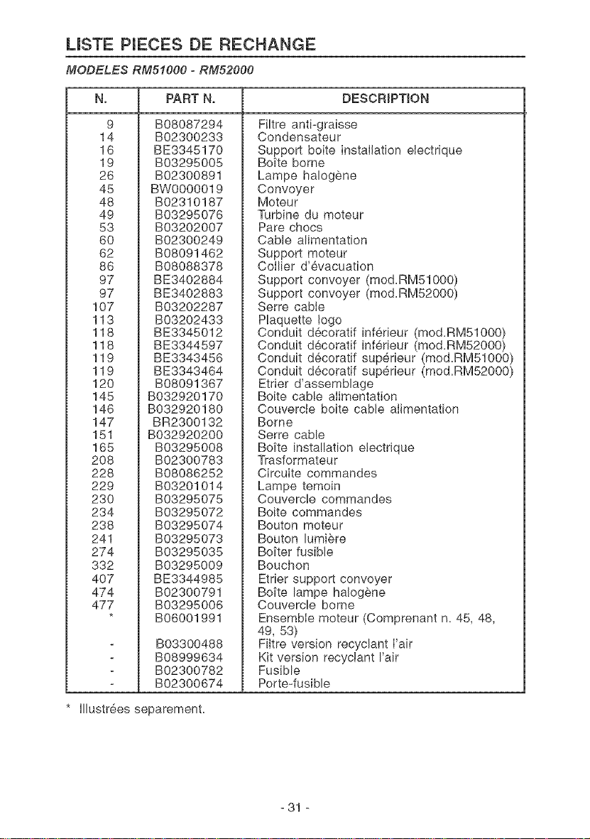
LISTE PIECES DE RECHANGE
MODELES RM51000 o RM52000
No PART N, DESCRIPTION
9
14
16
19
26
45
48
49
53
6O
62
86
97
97
107
113
118
118
119
119
120
145
146
147
151
165
2O8
228
229
230
234
238
241
274
332
4O7
474
477
B08087294
B02300233
BE3345170
B03295005
B02300891
BW0000019
B02310187
B03295076
B03202007
B02300249
B08091462
B08088378
BE3402884
BE3402883
B03202287
B03202433
BE3345012
BE3344597
BE3343456
BE3343464
B08091367
B032920170
B032920180
BR2300132
B032920200
B03295008
B02300783
B08086252
B03201014
B03295075
B03295072
B03295074
B03295073
B03295035
B03295009
BE3344985
B02300791
B03295006
B06001991
B03300488
B08999634
B02300782
B02300674
Filtre anti-graisse
Condensateur
Support boite installation eJectrique
Boi'te borne
Lampe halogene
Convoyer
Moteur
Turbine du moteur
Pare chocs
Cable alimentation
Support moteur
Collier d'evacuation
Support convoyer (mod.RM51000)
Support convoyer (mod.RM52000)
Serre cabte
Plaquette Jogo
Conduit decoratif inferieur (mod.RM51000)
Conduit decoratif inf6rieur (mod.RM52000)
Conduit decoratif sup@ieur (mod.RM51000)
Conduit decoratif superieur (mod.RM52000)
Etrier d'assemblage
Boite cable alimentation
Couvercte boite came aIimentation
Borne
Serre cable
Boi'te installation electrJque
Trasformateur
Circuite commandes
Lampe temoin
Couvercle commandes
Boite commandes
Bouton moteur
Bouton lumi_re
Boi'ter fusible
Bouchon
Etrier support convoyer
Boi'te lampe ha!ogene
Couvercle borne
Ensemble moteur (Comprenant n. 45, 48,
49, 53)
Filtre version recyclant Fair
Kit version recyctant Fair
Fusible
Porte-fusible
* Illustr6es separement.
- 31 -
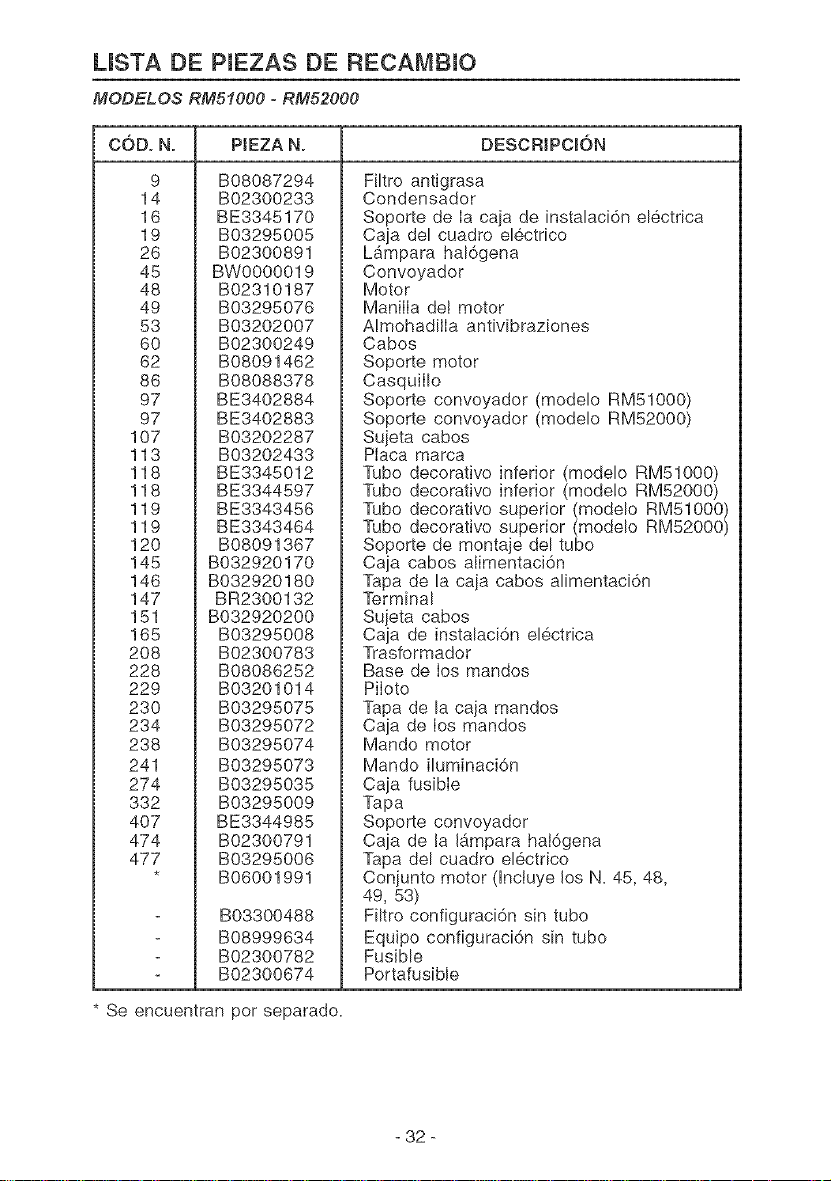
LISTA DE PIEZAS DE RECA[VIBIO
MODELOS RMSIO00 oRM52000
CODo N. PtEZA N. DESCRJPCION
9
14
16
19
26
45
48
49
53
6O
62
86
97
97
107
113
118
118
119
119
120
145
146
147
151
165
2O8
228
229
230
234
238
241
274
332
4O7
474
477
B08087294
B02300233
BE3345170
B03295005
B02300891
BW0000019
B02310187
B03295076
B03202007
B02300249
B08091462
B08088378
BE3402884
BE3402883
B03202287
B03202433
BE3345012
BE3344597
BE3343456
BE3343464
B08091367
B032920170
B032920180
BR2300132
B032920200
B03295008
B02300783
B08086252
B03201014
B03295075
B03295072
B03295074
B03295073
B03295035
B03295009
BE3344985
B02300791
B03295006
B06001991
B03300488
B08999634
B02300782
B02300674
Filtro antigrasa
Condensador
Soporte de Ia caja de instalaci6n electrica
Caja del cuadro electrico
L_mpara hal6gena
Convoyador
Motor
ManilIa de! motor
AImohadilIa antivibraziones
Cabos
Soporte motor
CasquilIo
Soporte convoyador (modelo RM51000)
Soporte convoyador (modelo RM52000)
Sujeta cabos
Placa marca
Tubo decoratJvo inferior (modelo RM51000)
Tubo decorativo inferior (mode!o RM52000)
Tubo decorativo superior (modelo RM51000)
Tubo decorativo superior (modelo RM52000)
Soporte de montaje del tubo
Caja cabos alimentaci6n
Tapa de la caja cabos alimentaci6n
Terminal
Sujeta cabos
Caja de instalaci6n electrica
Trasformador
Base de los mandos
Piloto
Tapa de la caja mandos
Caja de los mandos
Mando motor
Mando iluminaci6n
Caja fusible
Tapa
Soporte convoyador
Caja de la Jb_mparahal6gena
Tapa del cuadro electrico
Coniunto motor dnctuye los N. 45, 48,
49, 53)
Filtro configuraci6n sin tubo
Equipo configuraci6n sin tubo
Fusible
Portafusible
Se encuentran por separado.
- 32 -
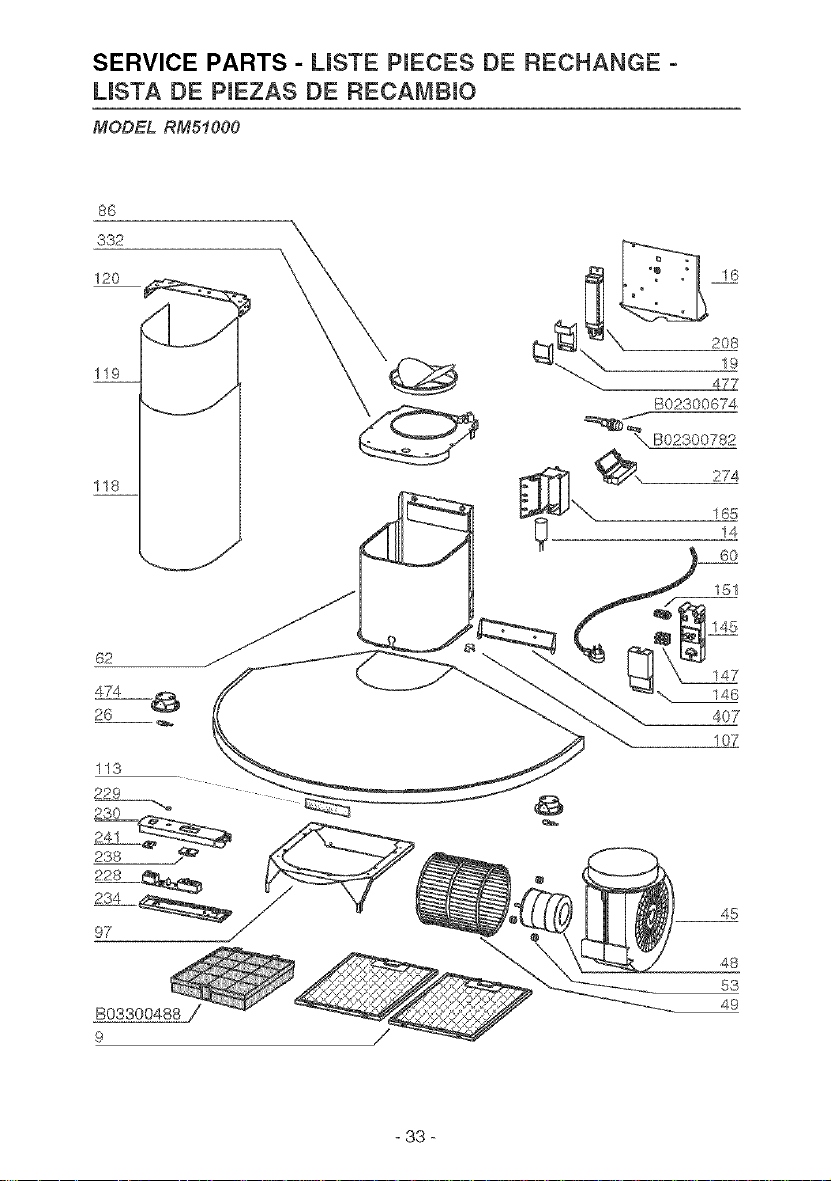
SERVICE PARTS - USTE PIECES DE RECHANGE -
USTA DE PIEZAS DE RECAMBIO
MODEL RM51000
86
332
120
119
118
62
474
26
113
229
230
24-1 =_
288
228
234 _
97 _
/
16
B02300674
==_?B02300782
274
165
14
60
151
145
147
146
407
107
48
53
49
- 33 -
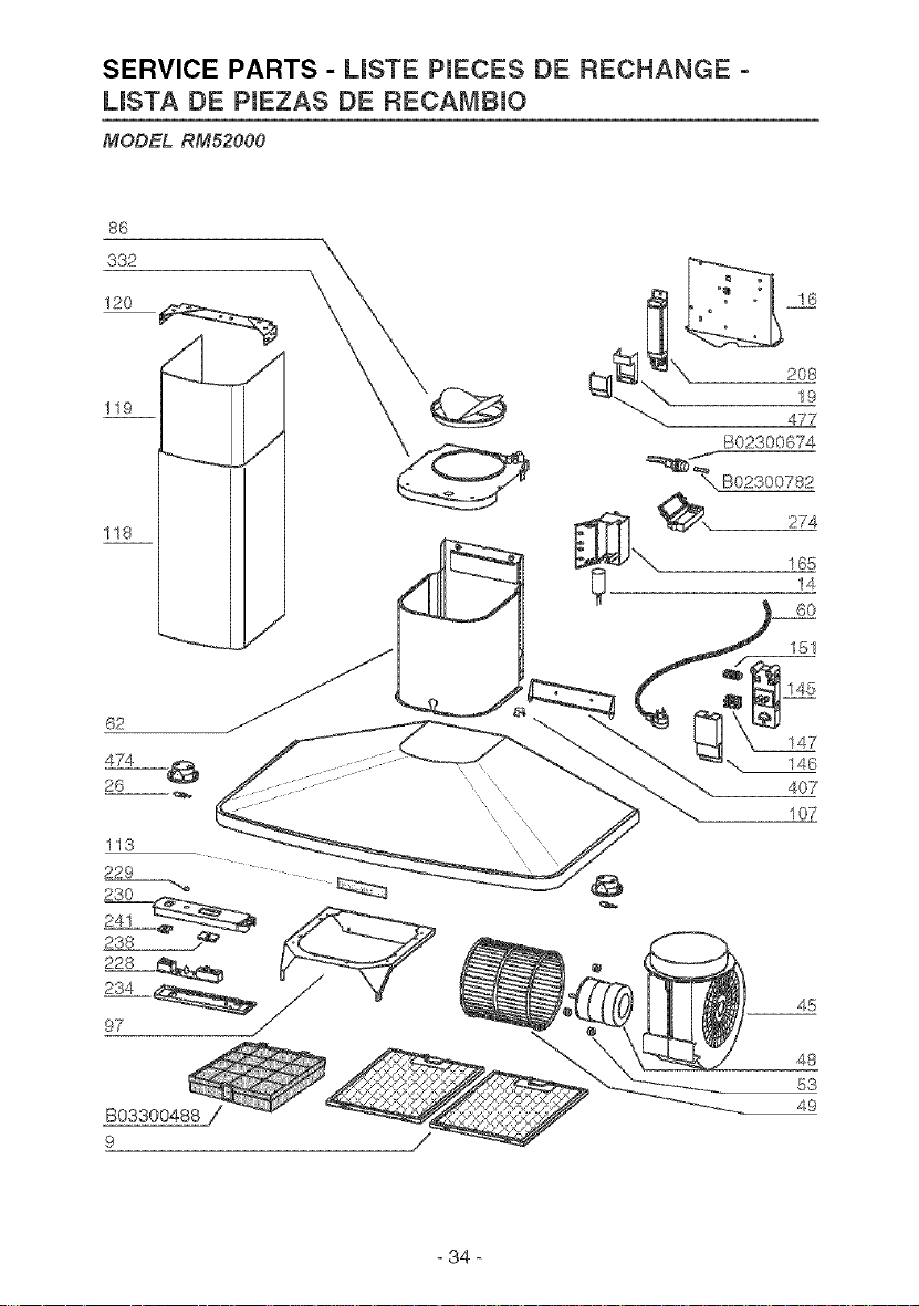
SERVICE PARTS - USTE PIECES DE RECHANGE -
USTA DE PIEZAS DE RECAMBIO
MODEL RM52000
86
119
118
62
26
113
229
230
241
238
228 _
234
97 _/
9 /
16
B02300674
,, 274
165
14
60
151
145
147
146
407
107
48
53
49
34


04306824/1