BROAN
INSTALLATION
INSTRUCTIONS
READ
&
SAVE
THESE
INSTRUCTIONS!
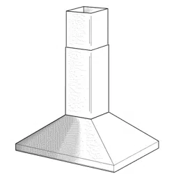
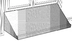
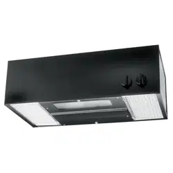
QL100
Series
Range
Hood
To
register
this
product
visit:
www.broan.com
A
INTENDED
FOR
DOMESTIC
COOKING
ONLY
A
IMPORTANT
SAFETY
INSTRUCTIONS
IMPORTANT
SAFETY
INSTRUCTIONS
WARNING
—
TO
REDUCE
THE
RISK
OF
FIRE,
ELECTRIC
SHOCK,
OR
INJURY
TO
PERSONS,
OBSERVE
THE
FOLLOWING:
1.
Use
this
unit
only
in
the
manner
intended
by
the
manufacturer.
If
you
have
questions,
contact
the
manufacturer
at
the
address
or
telephone
number
listed
in
the
warranty.
2.
Before
servicing
or
cleaning
unit,
switch
power
off at
service
panel
and
lock
service
panel
to
prevent
power
from
being
switched
on
accidentally.
When
the
service
disconnecting
means
cannot
be
locked,
securely
fasten
a
prominent
warning
device,
such
as
a
tag,
to
the
service
panel.
3.
Installation
work
and
electrical
wiring
must
be
done
by
a
qualified
person(s)
in
accordance
with
all
applicable
codes
and
standards,
including
fire-rated
construction
codes
and
standards.
4.
Sufficient
air
is
needed
for
proper
combustion
and
exhausting
of
gases
through
the
flue
(chimney)
of
fuel
burning
equipment
to
prevent
backdrafting.
Follow
the
heating
equioment
manufac-
turer’s
guideline
and
safety
standards
such
as
those
published
by
the
National
Fire
Protection
Association
(NFPA),
and
the
American
Society
for
Heating,
Refrigeration
and
Air
Conditioning
Engineers
(ASHRAE),
and
the
local
code
authorities.
5.
When
cutting
or
drilling
into
wall
or
ceiling,
do
not
damage
electrical
wiring
and
other
hidden
utilities.
6.
Ducted
fans
must
always
be
vented
to
the
outdoors.
7.
Use
with
approved
cord-connection
kit
only.
8.
To
reduce
the
risk
of
fire,
use
only
metal
ductwork.
T
1
O
REDUCE
THE
RISK
OF
A
RANGE
TOP
GREASE
FIRE:
Never
leave
surface
units
unattended
at
high settings.
Boilovers
cause
smoking
and
greasy
spillovers
that
may
ignite.
Heat
oils
slowly
on
low
or
medium
settings.
2.
Always
turn
hood
ON
when
cooking
at
high
heat
or
when
cook-
ing
flaming
foods.
3.
Clean
ventilating
fans
frequently.
Grease
should
not
be
allowed
to
accumulate
on
fan
or
filter.
4.
Use
proper
pan
size.
Always
use
cookware
appropriate
for
the
size
of
the
surface
element.
TO
REDUCE
THE
RISK
OF
INJURY
TO
PERSONS
IN
THE
EVENT
OF
A
RANGE
TOP
GREASE
FIRE,
OBSERVE
THE
FOLLOW-
ING*:
1.
SMOTHER
FLAMES
with
a
close-fitting
lid,
cookie
sheet,
or
metal
tray,
then
turn
off
the
burner.
BE
CAREFUL
TO
PREVENT
BURNS.
If
the
flames
do
not
go
out
immediately,
EVACUATE
AND
CALL
THE
FIRE
DEPARTMENT.
2.
NEVER
PICK
UPA
FLAMING
PAN
-
You
may
be
burned.
3.
DO
NOT
USE
WATER,
including
wet
dishcloths
or
towels
-
a
violent
steam
explosion
will
result.
4.
Use
an
extinguisher
ONLY
if:
A.
You
know
you
have
a
Class
ABC
extinguisher,
and
you
already
know
how
to
operate
it.
B.
The
fire
is
small
and
contained
in
the
area
where
it
start-
ed.
C.
The
fire
department
is
being
called.
D.
You
can
fight
the
fire
with
your
back
to
an
exit.
*
Based
on
“Kitchen
Firesafety
Tips”
published
by
NFPA.
1.
For
general
ventilating
use
only.
Do
not
use
to
exhaust
hazard-
ous
or
explosive
materials
and
vapors.
2.
To
reduce
the
risk
of
fire
or
electrical
shock,
this
range
hood
should
not
be
used
with
an
additional
speed
control
device.
3.
To
reduce
the
risk
of
shock,
disconnect
power
before
servic-
ing.
4.
To
reduce
the
risk
of
fire
and
to
properly
exhaust
air,
be
sure
to
duct
air
outside.
PLAN
THE
INSTALLATION
Recommended
mounting
height
is
18”
to
24”
from
the
bottom
of
the
range
hood
to
the
top
of
the
cooking
surface.
The
hood
should
be
mounted
to
the
bottom
of
a
standard
wall
cabinet.
If
the
hood
must
be
mounted
directly
to
a
wall,
secure
the
hood
to
wail
studs.
All
wiring
must
comply
with
local
codes
and
the
unit
must
be
properly
grounded.
The
hood
is
connected
to
a
110-120VAC
lighting
circuit
(15
amp)
in
the
circuit
breaker
or
fuse
box.
This
range
hood
is
“Convertible”
—
it
may
be
installed
as
a
ducted
or
as
a
non-ducted
unit.
IF
THE
RANGE
HOOD
IS
TO
BE
NON-DUCTED:
Purchase
non-ducted
(duct-free)
charcoal
filter
Model
BPQTF.
IF
THE
RANGE
HOOD
IS
TO
BE
DUCTED:
Ductwork
can
be
installed
vertically
or
horizontally.
Duct
runs
should
be
as
short
as
possible.
Avoid
the
use
of
elbows.
Use
duct tape
at
all
joints.
Do
not
use
duct
smaller
than
the
discharge
on
the
hood.
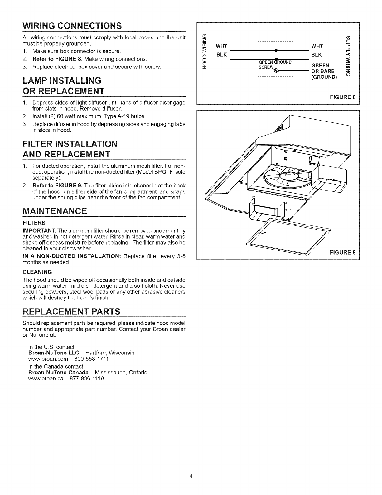
For
7”
round
ductwork
installation,
use
7”
round
damper,
Model
BP87
(97010792)
Purchased
damper
separately.
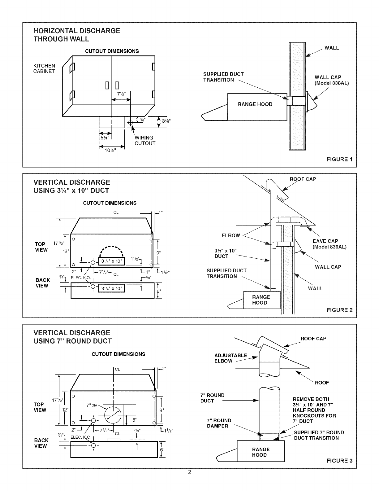
HORIZONTAL
DISCHARGE
THROUGH
WALL
CUTOUT
DIMENSIONS
KITCHEN
CABINET
(fl
[
i
me
|
|
SUPPLIED
DUCT
TRANSITION
WALL
a
WALL
CAP
(Model
838AL)
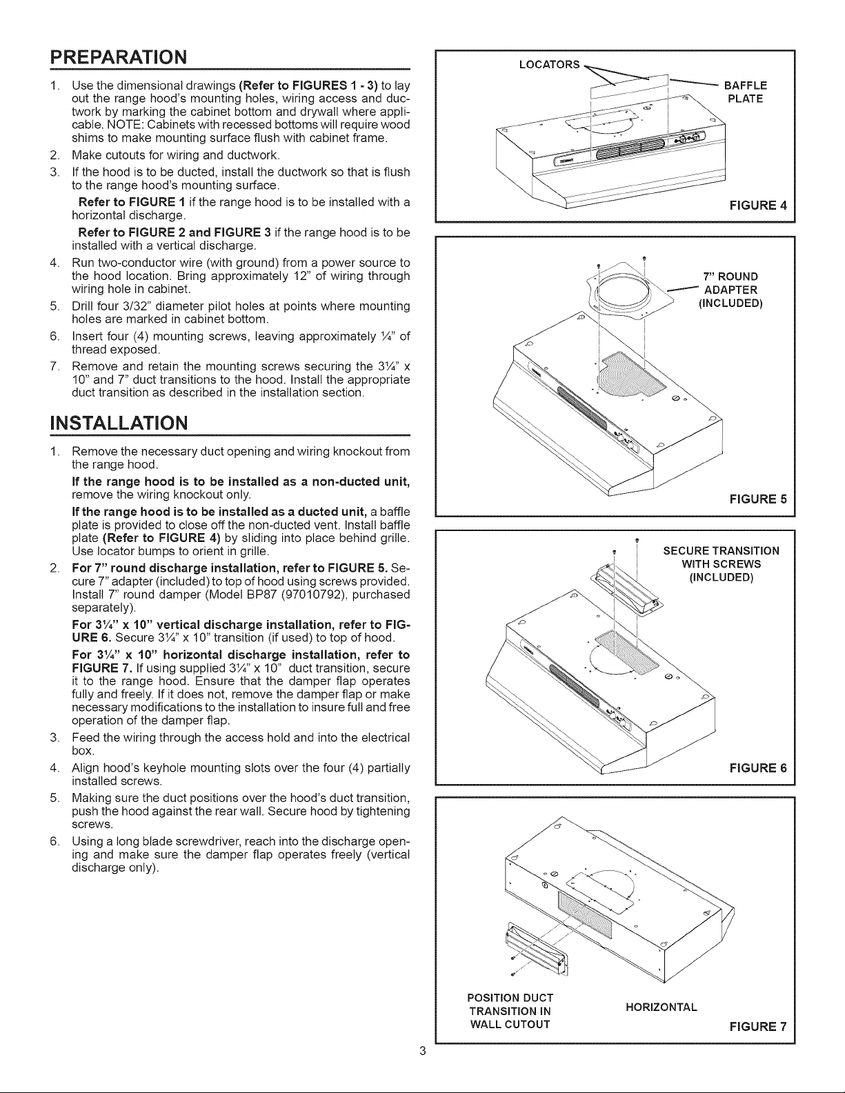
VERTICAL
DISCHARGE
USING
3%”
x
10”
DUCT
N
—
RANGE
HOOD
;
A
Ls
374"
5"
WIRING
CUTOUT
10%"
FIGURE
1
ROOF
CAP
CUTOUT
DIMENSIONS
jot
—_]
|—1"
I
\
KN
Ts
3
ELBOW
:
i
EAVE
CAP
Top
(17%
|
“
|
I
VIEW
42"
oN
|
314"
x
10"
(Model
836AL)
1
‘
.
pucT
———___
||,
--ofsmar]
"HI
A
WALL
CAP
et
la7iel
Lar
Lape
SUPPLIED
DUCT
BACK
wy
ELEC.
K.O.
|
pie"
TRANSITION
vw
SOG)
Tt
wa
£
RANGE
|
HOOD
FIGURE
2
VERTICAL
DISCHARGE
USING
7”
ROUND
DUCT
ROOF
CAP
CUTOUT
DIMENSIONS
ADJUSTABLE
_
ELBOW
——
CL
—|
|
1"
co)
“
;
\
ROOF
_
|
<2
Oo
|
7"
ROUND
17%"
l
pUCT
ye
REMOVE
BOTH
TOP
T"DIANG
3%"
x
10"
AND
7"
VIEW
12"
yD
9"
HALF
ROUND
i
—
-
|
KNOCKOUTS
FOR
>
-0-
KI
s
st
7"
ROUND
7"
DUCT
A
=
DAMPER
at
|.
7
|
7/9"
Lary"
at
0
ye!
CL
Sc
:
SUPPLIED
7"
ROUND
BACK
]_
ELEC.
KO.
|
_
ae
DUCT
TRANSITION
a
=
1
VIEW
O
I
L
RANGE
4d
<
HOOD
FIGURE
3
PREPARATION
1.
Use
the
dimensional
drawings
(Refer
to
FIGURES
1
-
3) to
lay
out
the
range
hood’s
mounting
holes,
wiring
access
and
duc-
twork
by
marking
the
cabinet
bottom
and
drywall
where
appli-
cable.
NOTE:
Cabinets
with
recessed
bottoms
will
require
wood
shims
to
make
mounting
surface
flush
with
cabinet
frame.
2.
Make
cutouts
for
wiring
and
ductwork.
3.
If
the
hood
is
to
be
ducted,
install
the
ductwork
so
that
is
flush
to
the
range
hood’s
mounting
surface.
Refer
to
FIGURE
1 if
the
range
hood
is
to
be
installed
with
a
horizontal
discharge.
Refer
to
FIGURE
2
and
FIGURE
3
if
the
range
hood
is
to
be
installed
with
a
vertical
discharge.
4.
Run
two-conductor
wire
(with
ground)
frorn
a
power
source
to
the
hood
location.
Bring
approximately
12”
of
wiring
through
wiring
hole
in
cabinet.
5.
Drill
four
3/32”
diameter
pilot
holes
at
points
where
mounting
holes
are
marked
in
cabinet bottom.
6.
Insert
four
(4)
mounting
screws,
leaving
approximately
1%”
of
thread
exposed.
7.
Remove
and
retain
the
mounting
screws
securing
the
3%”
x
10”
and
7”
duct
transitions
to
the
hood.
Install
the
appropriate
duct
transition
as
described
in
the
installation
section.
INSTALLATION
1.
Remove
the
necessary
duct
opening
and
wiring
knockout
from
the
range
hood.
lf
the
range
hood
is
to
be
installed
as
a
non-ducted
unit,
remove
the
wiring
Knockout
only.
lf
the
range
hood
is
to
be
installed
as
a
ducted
unit,
a
baffle
plate
is
provided
to
close
off
the
non-ducted
vent.
Install
baffle
plate
(Refer
to
FIGURE
4)
by
sliding
into
place
behind
grille.
Use
locator
burps
to
orient
in
grille.
2.
For
7”
round
discharge
installation,
refer
to
FIGURE
5.
Se-
cure
7”
adapter
(included)
to
top
of
hood
using
screws
provided.
Install
7”
round
damper
(Model
BP87
(97010792),
purchased
separately).
For
3%”
x
10”
vertical
discharge
installation,
refer
to
FIG-
URE
6.
Secure
3%”
x
10”
transition
(if
used)
to
top
of
hood.
For
3%”
x
10”
horizontal
discharge
installation,
refer
to
FIGURE
7.
If
using
supplied
314”
x
10”
duct
transition,
secure
it
to
the
range
hood.
Ensure
that
the
damper
flap
operates
fully
and
freely.
If
it
does
not,
remove
the
damper
flap
or
make
necessary
modifications
to
the
installation
to
insure
full
and
free
operation
of
the
damper
flap.
3.
Feed
the
wiring
through
the
access
hold
and
into
the
electrical
box.
4.
Align
hood’s
keyhole
mounting
slots
over
the
four
(4)
partially
installed
screws.
5.
Making
sure
the
duct
positions over
the
hood’s
duct
transition,
push
the
hood
against
the
rear
wall.
Secure
hood
by
tightening
screws.
6.
Using
a
long
blade
screwdriver,
reach
into
the
discharge
open-
ing
and
make
sure
the
damper
flap
operates
freely
(vertical
discharge
only).
LOCATORS
FIGURE
4
7”
ROUND
———
ADAPTER
(INCLUDED)
FIGURE
5
SECURE
TRANSITION
WITH
SCREWS
(INCLUDED)
FIGURE
6
POSITION
DUCT
TRANSITION
IN
WALL
CUTOUT
HORIZONTAL
FIGURE
7
WIRING
CONNECTIONS
All
wiring
connections
must
comply
with
local
codes
and
the
unit
must
be
properly
grounded.
1.
Make
sure
box
connector
is
secure.
2.
Refer
to
FIGURE
8.
Make
wiring
connections.
3.
Replace
electrical
box
cover
and
secure
with
screw.
LAMP
INSTALLING
OR
REPLACEMENT
1.
Depress
sides
of
light
diffuser
until
tabs
of
diffuser
disengage
from
slots
in
hood.
Remove
diffuser.
2.
Install
(2)
GO
watt
maximum,
Type
A-19
bulbs.
3.
Replace
difuser
in
hood
by
depressing
sides
and
engaging
tabs
in
slots
in
hood.
FILTER
INSTALLATION
AND
REPLACEMENT
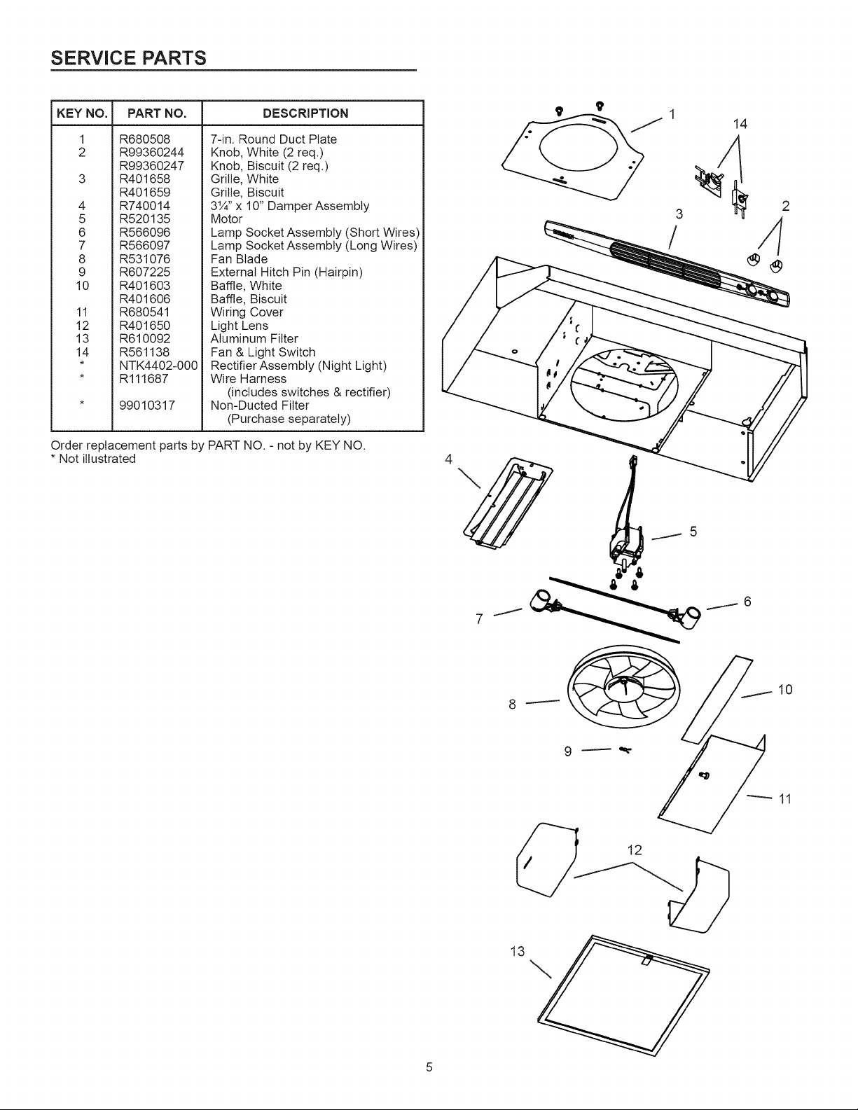
1.
For
ducted
operation,
install
the
aluminum
mesh
filter.
For
non-
duct
operation,
install
the
non-ducted
filter
(Model
BPQTF,
sold
separately).
2.
Refer
to
FIGURE
9.
The
filter
slides
into
channels
at
the
back
of
the
hood,
on
either
side
of
the
fan
compartment,
and
snaps
under
the
spring
clips
near
the front
of
the fan
compartment.
MAINTENANCE
FILTERS
IMPORTANT:
The
aluminum
filter
should
be
removed
once
monthly
and
washed
in
hot
detergent
water.
Rinse
in
clear,
warm
water
and
shake
off
excess
moisture
before
replacing.
The
filler
may
also
be
cleaned
in
your
dishwasher.
IN
A
NON-DUCTED
INSTALLATION:
Replace
filter
every
3-6
months
as
needed.
CLEANING
The
hood
should
be
wiped
off
occasionally
both
inside
and
outside
using
warm
water,
mild
dish
detergent
and
a
soft
cloth.
Never
use
scouring
powders,
steel
wool
pads
or
any
other
abrasive cleaners
which
will
destroy
the
hood’s
finish.
REPLACEMENT
PARTS
Should
replacement
paris
be
required,
please
indicate
hood
model
number
and
appropriate
part
number.
Contact
your
Broan
dealer
or
NuTone
at:
In
the
U.S.
contact:
Broan-NuTone
LLC
=
Hartford,
Wisconsin
www.broan.com
800-558-1711
In
the
Canada
contact:
Broan-NuTone
Canada
Mississauga,
Ontario
www.broan.ca
877-896-1119
HOOD
WIRING
BLK
2]
Cc
WHT
3
3
BLK
~<
=
GREEN
0
ORBARE
2
(GROUND)
FIGURE
8
FIGURE
9
SERVICE
PARTS
KEY
NO.;
PART
NO.
DESCRIPTION
1
R680508
7-in.
Round
Duct
Plate
2
R99360244
Knob,
White
(2
req.)
R99360247
Knob,
Biscuit
(2
req.)
3
R401658
Grille,
White
R401659
Grille,
Biscuit
4
R740014
3%”
x
10”
Damper
Assembly
5
R520135
Motor
6
R566096
Lamp
Socket
Assembly
(Short
Wires)
7
R566097
Lamp
Socket
Assembly
(Long
Wires)
8
R531076
Fan
Blade
9
R607225
External
Hitch
Pin
(Hairpin)
10
R401603
Baffle,
White
R401606
Baffle,
Biscuit
11
R680541
Wiring
Cover
12
R401650
Light
Lens
13
R610092
Alurninum
Filter
14
R561138
Fan
&
Light
Switch
*
NTK4402-000}
Rectifier
Assembly
(Night
Light)
*
R111687
Wire
Harness
(includes
switches
&
rectifier)
*
99010317
Non-Ducted
Filter
(Purchase
separaiely)
Order
replacement
paris
by
PART
NO.
-
not
by
KEY
NO.
*
Not
illustrated
13
WARRANTY
BROAN
ONE
YEAR
LIMITED
WARRANTY
Broan
warrants
to
the
original
consumer
purchaser
of
its
products
that
such
products
will
be
free
from
defects
in
materials
or
work-
manship
for
a
period
of
one
year
from
the
date
of
original
purchase.
THERE
ARE
NO
OTHER
WARRANTIES,
EXPRESS
OR
IM-
PLIED,
INCLUDING,
BUT
NOT
LIMITED
TO,
IMPLIED
WARRANTIES
OF
MERCHANTABILITY
OR
FITNESS
FOR
APARTICULAR
PURPOSE.
During
this
one-year
period,
Broan
will,
at
its
option,
repair
or
replace,
without
charge,
any
product
or
part
which
is
found
to
be
defec-
tive
under
normal
use
and
service.
THIS
WARRANTY
DOES
NOT
EXTEND
TO
FLUORESCENT
LAMP
STARTERS
AND
TUBES.
This
warranty
does
not
cover
(a)
normal
maintenance
and service
or
(b)
any
products
or
paris
which
have
been
subject
to
misuse,
negligence,
accident,
improper
maintenance
or
repair
(other
than
by
Broan),
faulty
installation
or
installation
contrary
to
recommended
installation
instructions.
The
duration
of
any
implied
warranty
is
limited
to
the
one-year
period
as
specified
for
the
express
warranty.
Some
states
do
not
allow
limitation
on
how
long
an
implied
warranty
lasts,
so
the
above
limitation
may
not
apply
to
you.
BROAN’S
OBLIGATION
TO
REPAIR
OR
REPLACE,
AT
BROAN’S
OPTION,
SHALL
BE
THE
PURCHASER’S
SOLE
AND
EXCLU-
SIVE
REMEDY
UNDER
THIS
WARRANTY.
BROAN
SHALL
NOT
BE
LIABLE
FOR
INCIDENTAL,
CONSEQUENTIAL
OR
SPECIAL
DAMAGES
ARISING
OUT
OF
OR
IN
CONNECTION
WITH
PRODUCT
USE
OR
PERFORMANCE.
Some
states
do
not
allow
the
exclusion
or
limitation
of
incidental
or
consequential
damages,
so
the
above
limitation
or
exclusion
may
not
apply
to
you.
This
warranty
gives
you
specific
legal
rights,
and
you
may
also
have
other
rights,
which
vary
from
state
to
state.
This
warranty
su-
persedes
all
prior
warranties.
To
qualify
for
warranty
service,
you
must
(a)
notify
the
company
at
the
address
or
phone
number
below
(b)
give
the
model
number
and
part
identification
and
(c)
describe
the
nature
of
any
defect
in
the
product
or
part.
At
the
time
of
requesting
warranty
service,
you
must
present
evidence
of
the
original
purchase
daie.
In
the
U.S.
contact:
Broan-NuTone
LLC
Hartford,
Wisconsin
www.broan.com
800-558-1711
In
the
Canada
contact:
Broan-NuTone
Canada
Mississauga,
Ontario
www.broan.ca
877-896-1119
Product
specifications
subject
to
change
without
notice.
Printed
in
U.S.A.,
Rev.
02/08,
Part No.
628029B
BROAN
INSTRUCCIONES
DE
INSTALACION
jLEA
Y
GUARDE
ESTAS
INSTRUCCIONES!
Campana
de
Cocina
Serie
QL100
Para
registrar
este
producto
visite:
www.broan.com
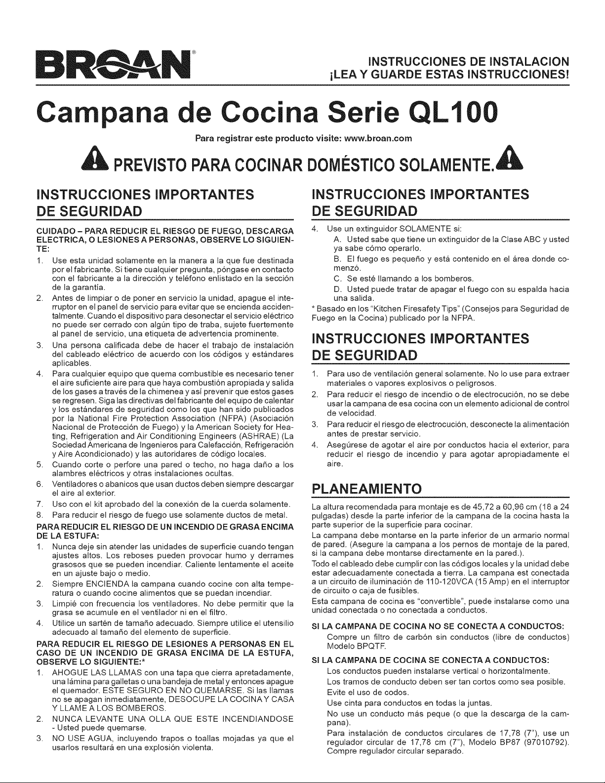
A
PREVISTO
PARA
COCINAR
DOMESTICO
SOLAMENTE.
4&
INSTRUCCIONES
IMPORTANTES
DE
SEGURIDAD
INSTRUCCIONES
IMPORTANTES
DE
SEGURIDAD
CUIDADO
—
PARA
REDUCIR
EL
RIESGO
DE
FUEGO,
DESCARGA
ELECTRICA,
O
LESIONES
A
PERSONAS,
OBSERVE
LO
SIGUIEN-
TE:
1.
Use
esta
unidad
solamente
en
la
manera
a
la
que
fue
destinada
por
el
fabricante.
Si
tiene
cualquier
pregunta,
p6ngase
en
contacto
con
el
fabricante
a
la
direccién
y
teléfono
enlistado
en
la
seccién
de
la
garantia.
2.
Antes
de
limpiar
o
de
poner
en
servicio
la
unidad,
apague
el
inte-
rruptor
en
el
panel
de
servicio
para
evitar
que
se
encienda
acciden-
talmente.
Cuando
el
dispositivo
para
desonectar
el
servicio
eléctrico
no
puede
ser
cerrado
con
algun
tipo
de
traba,
sujete
fuertemente
al
panel
de
servicio,
una
etiqueta
de
advertencia
prominente.
3.
Una
persona
calificada
debe
de
hacer
el
trabajo
de
instalacién
del
cableado
eléctrico
de
acuerdo
con
los
cddigos
y
estandares
aplicables.
4.
Para
cualquier
equipo
que
quema
combustible
es
necesario
tener
el
aire
suficiente
aire
para
que
haya
combustion
apropiada
y
salida
de
los
gases
a
través
de
la
chimenea
y
asi
prevenir
que
estos
gases
se
regresen.
Siga
las
directivas
del
fabricante
del
equipo
de
calentar
y
los
estandares
de
seguridad
como
los
que
han
sido
publicados
por
la
National
Fire
Protection
Association
(NFPA)
(Asociacién
Nacional
de
Protecciédn
de
Fuego)
y
la
American
Society
for
Hea-
ting,
Refrigeration
and
Air
Conditioning
Engineers
(ASHRAE)
(La
Sociedad
Americana
de
Ingenieros
para
Calefaccién,
Refrigeracién
y
Aire
Acondicionado)
y
las
autoridares
de
cddigo
locales.
5.
Cuando
corte
o
perfore
una
pared
o
techo,
no
haga
dafio
a
los
alambres
eléctricos
y
otras
instalaciones
ocultas.
6.
Ventiladores
o
abanicos
que
usan
ductos
deben
siempre
descargar
el
aire
al
exterior.
7.
Uso
con
el kit
aprobado
del
la
conexién
de
la
cuerda
solamente.
8.
Para
reducir
el
riesgo
de
fuego
use
solamente
ductos
de
metal.
PARA
REDUCIR
EL
RIESGO
DE
UN
INCENDIO
DE
GRASAENCIMA
DE LA
ESTUFA:
1.
Nunca
deje
sin
atender
las
unidades
de
superficie
cuando
tengan
ajustes
altos.
Los
reboses
pueden
provocar
humo
y
derrames
grasosos
que
se
pueden
incendiar.
Caliente
lentamente
el
aceite
en
un
ajuste
bajo
o
medio.
2.
Siempre
ENCIENDA
la
campana
cuando
cocine
con
alta
tempe-
ratura
o
cuando
cocine
alimentos
que
se
puedan
incendiar.
3.
Limpié
con
frecuencia
los
ventiladores.
No
debe
permitir
que
la
grasa
se
acumule
en
el
ventilador
ni
en
el
filtro.
4.
Ultilice
un
sartén
de
tamafio
adecuado.
Siempre
utilice
el
utensilio
adecuado
al
tamafio
del
elemento
de
superficie.
PARA
REDUCIR
EL
RIESGO
DE
LESIONES
A
PERSONAS
EN EL
CASO
DE
UN
INCENDIO
DE
GRASA
ENCIMA
DE
LA
ESTUFA,
OBSERVE
LO
SIGUIENTE:*
1.
AHOGUE
LAS
LLAMAS
con
una
tapa
que
cierra
apretadamente,
una
lamina
para
galletas
o
una
bandeja
de
metal
y
entonces
apague
el
quemador.
ESTE
SEGURO
EN
NO
QUEMARSE.
Si
las
llamas
no
se
apagan
inmediatamente,
DESOCUPE
LA
COCINAY
CASA
Y
LLAME
ALOS
BOMBEROS.
2.
NUNCA
LEVANTE
UNA OLLA
QUE
ESTE
INCENDIANDOSE
-
Usted
puede
quemarse.
3.
NO
USE
AGUA,
incluyendo
trapos
o
toallas
mojadas
ya
que
el
usarlos
resultara
en
una
explosi6n
violenta.
4.
Use
un
extinguidor
SOLAMENTE
si:
A.
Usted
sabe
que
tiene
un
extinguidor
de
la
Clase
ABC
y
usted
ya
sabe
cémo
operarlo.
B.
El
fuego
es
pequefio
y
esta
contenido
en
el
area
donde
co-
menzo.
C.
Se
esté
llamando
a
los
bomberos.
D.
Usted
puede
tratar
de
apagar
el
fuego
con
su
espalda
hacia
una
salida.
*
Basado
en
los
“Kitchen
Firesafety
Tips”
(Consejos
para
Seguridad
de
Fuego
en
la
Cocina)
publicado
por
la
NFPA.
INSTRUCCIONES
IMPORTANTES
DE
SEGURIDAD
1.
Para
uso
de
ventilacién
general
solamente.
No
lo
use
para
extraer
materiales
o
vapores
explosivos
o
peligrosos.
2.
Para
reducir
el
riesgo
de
incendio
o
de
electrocucién,
no
se
debe
usar
la
campana
de
esa
cocina
con
un
elemento
adicional
de
control
de
velocidad.
3.
Para
reducir
el
riesgo
de
electrocucién,
desconecte
la
alimentacién
antes
de
prestar
servicio.
4.
Asegurese
de
agotar
el
aire
por
conductos
hacia
el
exterior,
para
reducir
el
riesgo
de
incendio
y
para
agotar
apropiadamente
el
aire,
PLANEAMIENTO
La
altura
recomendada
para
montaje
es
de
45,72
a
60,96 cm
(18
a
24
pulgadas)
desde
la
parte
inferior
de
la
campana
de
la
cocina
hasta
la
parte
superior
de
la
superficie
para
cocinar.
La
campana
debe
montarse
en
la
parte
inferior
de
un
armario
normal
de
pared.
(Asegure
la
campana
a
los
pernos
de
montaje
de
la
pared,
si
la
campana
debe
montarse
directamente
en
la
pared.).
Todo
el
cableado
debe
cumplir
con
las
cédigos
locales
y
la
unidad
debe
estar
adecuadamente
conectada
a
tierra.
La
campana
est
conectada
a
un
circuito
de
iluminacién
de
110-120VCA
(15
Amp)
en
el
interruptor
de circuito
o
caja
de
fusibles.
Esta
campana
de
cocina
es
“convertible”,
puede
instalarse
como
una
unidad
conectada
o
no
conectada
a
conductos.
SILA
CAMPANA
DE
COCINA
NO
SE
CONECTA
A
CONDUCTOS:
Compre
un
filtro
de
carbén
sin
conductos
(libre
de
conductos)
Modelo
BPQTF.
SILA
CAMPANA
DE
COCINA
SE
CONECTA
A
CONDUCTOS:
Los
conductos
pueden
instalarse
vertical
o
horizontalmente.
Los
tramos
de
conducto
deben
ser
tan
cortos
como
sea
posible.
Evite
el
uso
de
codos.
Use
cinta
para
conductos
en
todas
la
juntas.
No
use
un
conducto
mas
peque
(o
que
la
descarga
de
la
cam-
pana).
Para
instalacién
de
conductos
circulares
de
17,78
(7”),
use
un
regulador
circular
de
17,78
cm
(7”),
Modelo
BP87/
(97010792).
Compre
regulador
circular
separado.
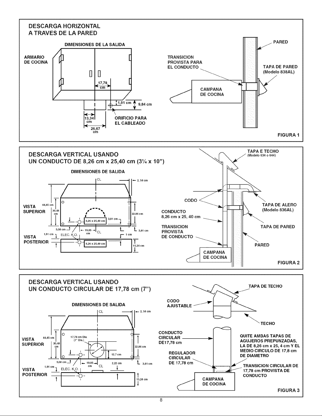
DESCARGA
HORIZONTAL
A
TRAVES
DE
LA
PARED
DIMENSIONES
DE
LA
SALIDA
ARMARIO
iL
DE
COCINA
d
41,91
cm
»
v
y!
13,34
cm
26,67
cm
ORIFICIO
PARA
EL
CABLEADO
9,84
cm
TRANSICION
PROVISTA
PARA
EL
CONDUCTO
PARED
a
TAPA
DE
PARED
(Modelo
838AL)
CAMPANA
DE
COCINA
ia
er]
FIGURA
1
DESCARGA
VERTICAL
USANDO
UN
CONDUCTO
DE
8,26
cm
x
25,40
cm
(3%
x
10”)
DIMENSIONES
DE
SALIDA
{ct
VISTA
44,45
cm
°
4
SUPERIOR
[°248
“os
f
4
opera]
5,08
em
[a
19,05
|
CL
L
cm
VISTA
1,91
em
1
ELEC.
KO.
T
tem
POSTERIOR
FTO
2s
x2580
em]
]
coDpo
TAPA
E
TECHO
(Modelo
634
0
644)
N
TAPA
DE
ALERO
CONDUCTO
8,26
cm
x
25,
40
cm
a
TRANSICION
PROVISTA
DE
CONDUCTO
ne
(Modelo
836AL)
TAPA
DE
PARED
r
PARED
CAMPANA
DE
COCINA
FIGURA
2
DESCARGA
VERTICAL
USANDO
UN
CONDUCTO
CIRCULAR
DE
17,78
cm
(7”)
DIMENSIONES
DE
SALIDA
See
«
2,54cm
|
cL
i
—
J
|
. 1
Oj
VISTA
44,45
cm
es
Da
r
:
SUPERIOR
|
°°
.
ea
J
l
O
“7h
-
we)
|
12,7
cm
i
5,08
cm_t
J
19,05
|
2.22
em
‘
1,91
om cm
cL
VISTA
een)
ELEC.
KO.
| {
POSTERIOR
|
-O
-
t
15,24
cm
CcoDO
AJUSTABLE
<a
ae,
a
CONDUCTO
CIRCULAR
———__»-
DE17,78
cm
REGULADOR
CIRCULAR
DE
17,78
cm
a
CAMPANA
DE
COCINA
TAPA
DE
TECHO
NN
TECHO
QUITE
AMBAS
TAPAS
DE
AGUJEROS
PREPUNZADAS,
LA
DE
8,26
cm
x
25,
4cm
Y
EL
MEDIO
CIRCULO
DE
17,8
cm
DE
DIAMETRO
TRANSICION
CIRCULAR
DE
17,78
cm
PROVISTA
DE
CONDUCTO
FIGURA
3
PREPARACION
1.
Use
los
dibujos
dimensionales
(FIGURAS
1
-
3)
para
disponer
los
orificios
de
montaje
de
la
campana,
acceso
de!
cableado
y
conductos,
marcando
el
fondo
del
armario
y
el
tabique
donde
sea
aplicable.
NOTA:
Los
gabinetes
con
los
fondos
ahuecados
requeriran
las
calzas
de
madera
hacer
rubor
de
la
superficie
de
montaje
con
el
marco
de
gabinete.
2.
Efecto
e
los
cories
para
el
cableado
y
el
conducto.
3.
Instale
el
conducto
de
manera
que
esié
al
ras
con
la
superficie
de
montaje
de
la
campana
de
cocina,
sila
campana
se
conecta
a
un
conducto.
Si
la
campana
de
la
cocina
se
instala
con
una
descarga
hori-
zontal,
refiérase
a
la
FIGURA
1.
Sila
campana
dela
cocina
se
instala
con
una
descarga
vertical,
refiérase
a
las
FIGURAS
2
y
3.
4.
Tienda
un
cable
de
dos
conductores
(con
conexi6n
a
tierra)
desde
una
fuente
de
potencia
a
la
ubicacién
de
la
campana.
Traiga
30,48 cm
(12”)
de
cableado
aproximadamente
a
través
del
orificio
de
cableado
en
el
armario.
5.
Taladre
cuatro
orificios
piloto
de
0,24
cm
(3/32”)
de
diametro
en
los
puntos
donde
estan
marcados
los
orificios
de
montaje
en
el
fondo
del
armario.
6.
Inserte
cuatro
(4)
tornillo
de
montaje,
dejando
aproximadamente
0,64
cm
(1/4”)
de
rosca
expuesta.
7.
Extraiga
y
guarde
los
tornillos
de
montaje,
asegurando
las
transiciones
de
conducto
de
8,26
cm
x
25,40
cm
(31%”
x
10”)
y
17,78
cm
(7’)
ala
campana.
Instale
la
transicién
de
conducto
apropiada
seguin
se
describe
en
la
seccién
de
instalacion
INSTALACION
1.
Extraigala
abertura
de
conducto
y
el
orificio
ciego
de
cableado
necesarios,
de
la
campana
de
cocina.
Si
la
campana
de
cocina
se
instala
como
una
unidad
sin
conductos,
extraiga
el
orificio
ciego
del
cableado
solamente.
Si
la
campana
de
cocina
se
instala
como
una
unidad
con
conducto,
se
provee
una
placa
deflectora
para
cerrar
el
ven-
tilador
sin
conducto.
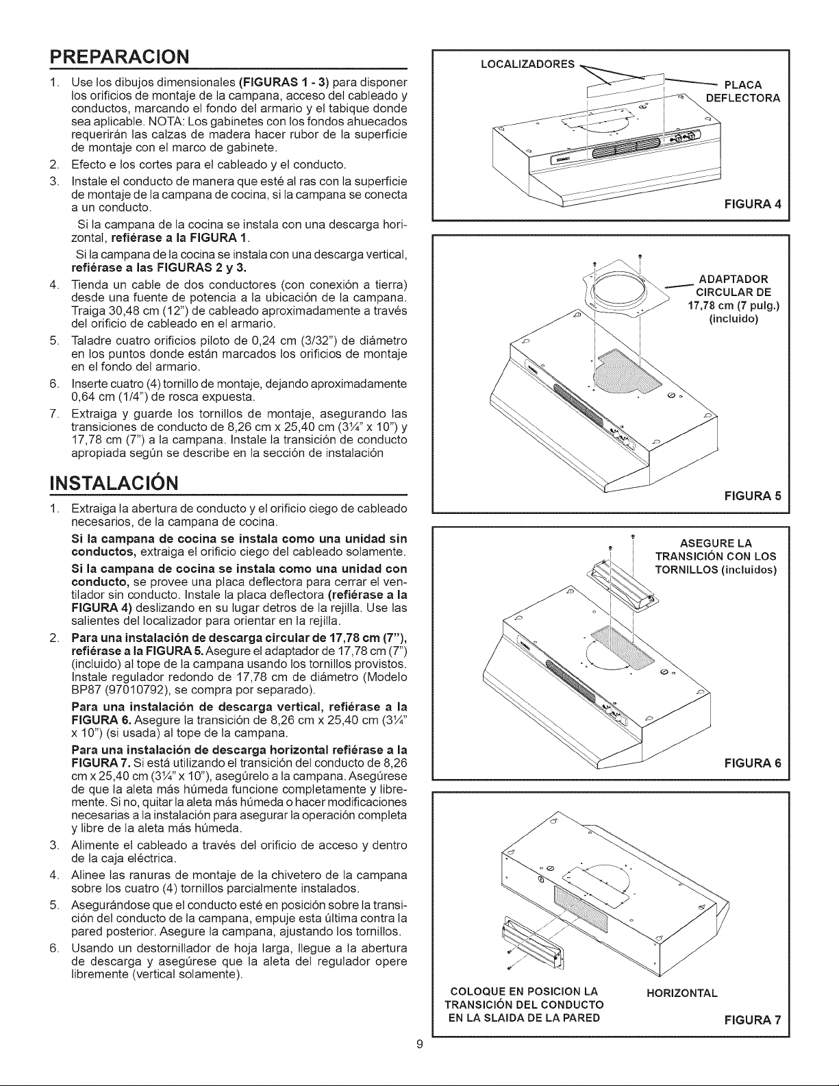
Instale
la
placa
deflectora
(refiérase
a
la
FIGURA
4)
deslizando
en
su
lugar
detros
de
Ia
rejilla.
Use
las
salientes
del
localizador
para
orientar
en
la
rejilla.
2.
Para
una
instalacién
de
descarga
circular
de
17,78
em
(7”),
refiérase
ala
FIGURA
5.
Asegure
el
adaptador
de
17,78
cm
(7”)
(incluido)
al
tope
de
la
campana
usando
los
tornillos
provistos.
Instale
regulador
redondo
de
17,78
cm
de
diametro
(Modelo
BP87
(97010792),
se
compra
por
separado).
Para
una
instalacién
de
descarga
vertical,
refiérase
a
la
FIGURA
6.
Asegure
la
transicién
de
8,26
cm
x
25,40
cm
(3%”
x
10”)
(si
usada)
al
tope
de
la
campana.
Para
una
instalacién
de
descarga
horizontal
refiérase
a
la
FIGURA
7.
Si
esta
utilizando
el
transicién
del
conducto
de
8,26
cm
x
25,40
cm
(314’
x
10”),
asegurelo
ala
campana.
Asegurese
de
que
la
aleta
mas hiumeda
funcione
completamenie
y
libre-
mente.
Sino,
quitar
la
aleta
mas
humeda
o
hacer
modificaciones
necesarias
ala
instalaci6n
para
asegurar
la
operacioén
completa
y
libre
de
la
aleta
mas
humeda.
3.
Alimente
el
cableado
a
través
del
orificio
de
acceso
y
dentro
de
la
caja
eléctrica.
4.
Alinee
las
ranuras
de
montaje
de
la
chivetero
de
la
campana
sobre
los
cuatro
(4)
tornillos
parcialmenie
instalados.
5.
Asegurandose
que
el
conducto
esté
en
posicién
sobre
la
transi-
cién
del
conducto
de
la
campana,
empuje
esta
ultima
contra
la
pared
posterior.
Asegure
la
campana,
ajustanco
los
tornillos.
6.
Usando
un
destornillador
de
hoja
larga,
llegue
a
la
abertura
de
descarga
y
asegurese
que
la
aleta
del
regulador
opere
libremente
(vertical
solamente).
FIGURA
4
ADAPTADOR
CIRCULAR
DE
17,78
cm
(7
pulg.)
(incluido)
FIGURA
5
ASEGURE
LA
TRANSICION
CON
LOS
TORNILLOS
(incluidos)
FIGURA
6
COLOQUE
EN
POSICION
LA
TRANSICION
DEL
CONDUCTO
EN LA
SLAIDA
DE
LA
PARED
HORIZONTAL
FIGURA
7
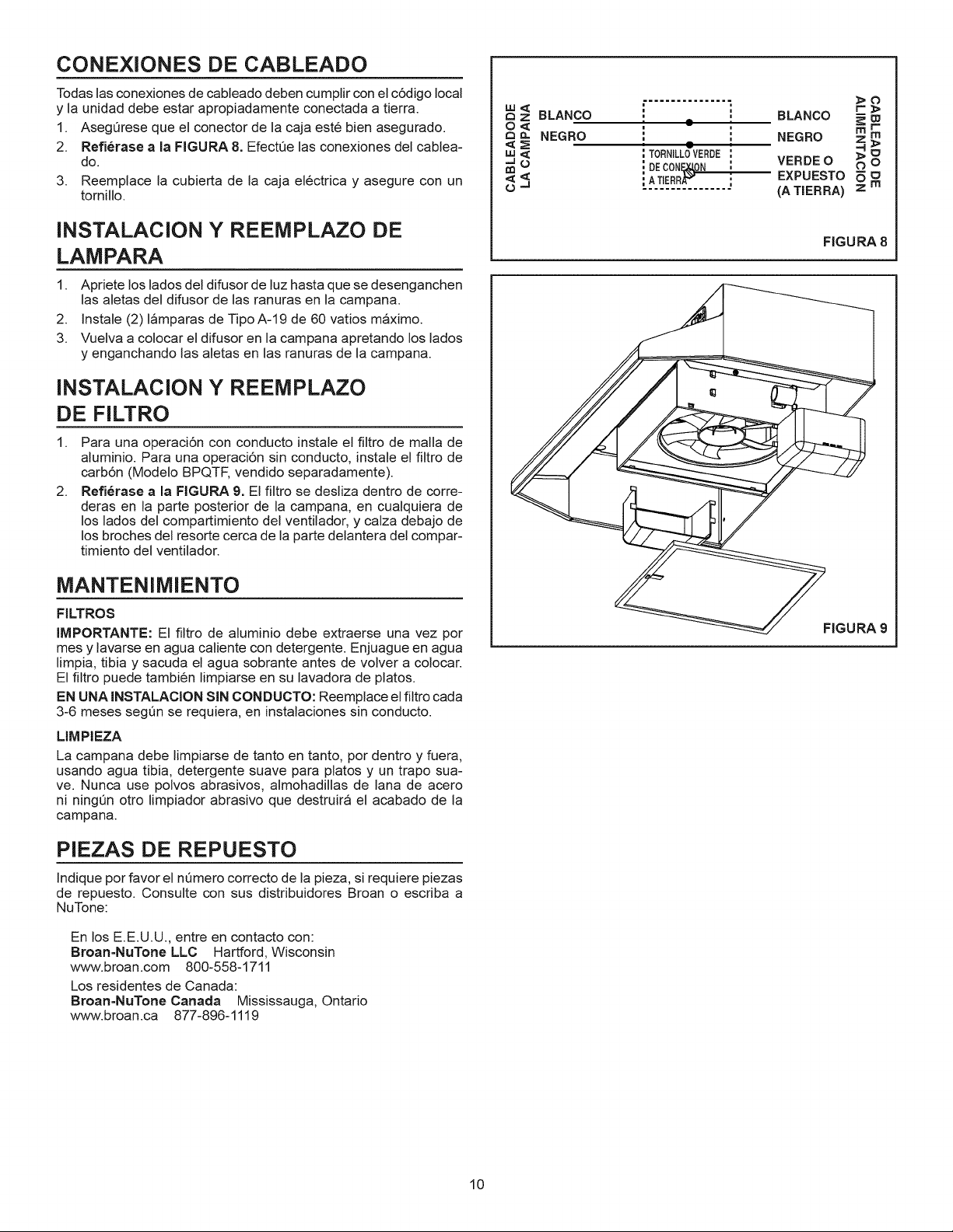
CONEXIONES
DE
CABLEADO
Todas
las
conexiones
de
cableado
deben
cumplir
con
el
cdédigo
local
y
la
unidad
debe
estar
apropiadamente
conectada
a
tierra.
WS
BLANCO
poet
BLANCO
E >
1.
Asegurese
que
el
conector
de
la
caja
esté
bien
asegurado.
2 <
NEGRO
'
°
:
NEGRO
x a
2.
Refiérase
ala
FIGURA
8.
Efeciue
las
conexiones
del
cablea-
=
=
TORNILLG
VERDE
S 5
do.
ae
1
DE
CONE
YON
VERDEO
90
3.
Reemplace
la
cubierta
de
la
caja
eléctrica
y
asegure
con
un
a s
iATERRAT
os
EXPUESTO
9 m
tornillo.
(A
TIERRA)
INSTALACION
Y
REEMPLAZO
DE
cIGURA
8
LAMPARA
1.
Apriete
los
lados
del
difusor
de
luz
hasta
que
se
desenganchen
las
aletas
del
difusor
de
las
ranuras
en
la
campana.
2.
Instale
(2)
lamparas
de
Tipo
A-19
de
60
vatios
maximo.
3.
Vuelva
a
colocar
el
difusor
en
la
campana
apretando
los
lados
y
enganchando
las
aletas
en
las
ranuras
de
la
campana.
INSTALACION
Y
REEMPLAZO
DE
FILTRO
1.
Para
una
operaci6én
con
conducto
instale
el
filtro
de
malla
de
aluminio.
Para
una
operacién
sin
conducto,
instale
el
filtro
de
carbon
(Modelo
BPQTF,
vendido
separadamente).
2.
Refiérase
a
la
FIGURA
9. El
filtro
se
desliza
dentro
de
corre-
deras
en
la
parte
posterior
de
la
campana,
en
cualquiera
de
los
lados
del
compartimiento
del
ventilador,
y
calza
debajo
de
los
broches
del
resorte
cerca
de
la
parte
delantera
del
compar-
timiento
del
ventilador.
MANTENIMIENTO
FILTROS
IMPORTANTE:
El
filtro
de
aluminio
debe
extraerse
una
vez
por
FIGURA
9
mes
y
lavarse
en
agua
caliente
con
detergente.
Enjuague
en
agua
limpia,
tibia
y
sacuda
el
agua
sobrante
antes
de
volver
a
colocar.
El
filtro
puede
también
limpiarse
en
su
lavadora
de
platos.
EN
UNA
INSTALACION
SIN
CONDUCTO:
Reemplace
el
filtro
cada
3-6
meses
segtin
se
requiera,
en
instalaciones
sin
conducto.
LIMPIEZA
La
campana
debe
limpiarse
de
tanto
en
tanto,
por
dentro
y
fuera,
usando
agua
tibia,
detergente
suave
para
platos
y
un
trapo
sua-
ve.
Nunca
use
polvos
abrasivos,
almohadillas
de
lana
de
acero
ni
ningtin
otro
limpiador
abrasivo
que
destruira
el
acabado
de
la
campana.
PIEZAS
DE
REPUESTO
Indique
por
favor
el
numero
correcto
de
la
pieza,
si
requiere
piezas
de
repuesto.
Consulte
con
sus
distribuidores
Broan
o
escriba
a
NuTone:
En
los
E.E.U.U.,
entre
en
contacto
con:
Broan-NuTone
LLC
=
Hartford,
Wisconsin
www.broan.com
800-558-1711
Los
residentes
de
Canada:
Broan-NuTone
Canada
Mississauga,
Ontario
www.broan.ca
877-896-1119
10
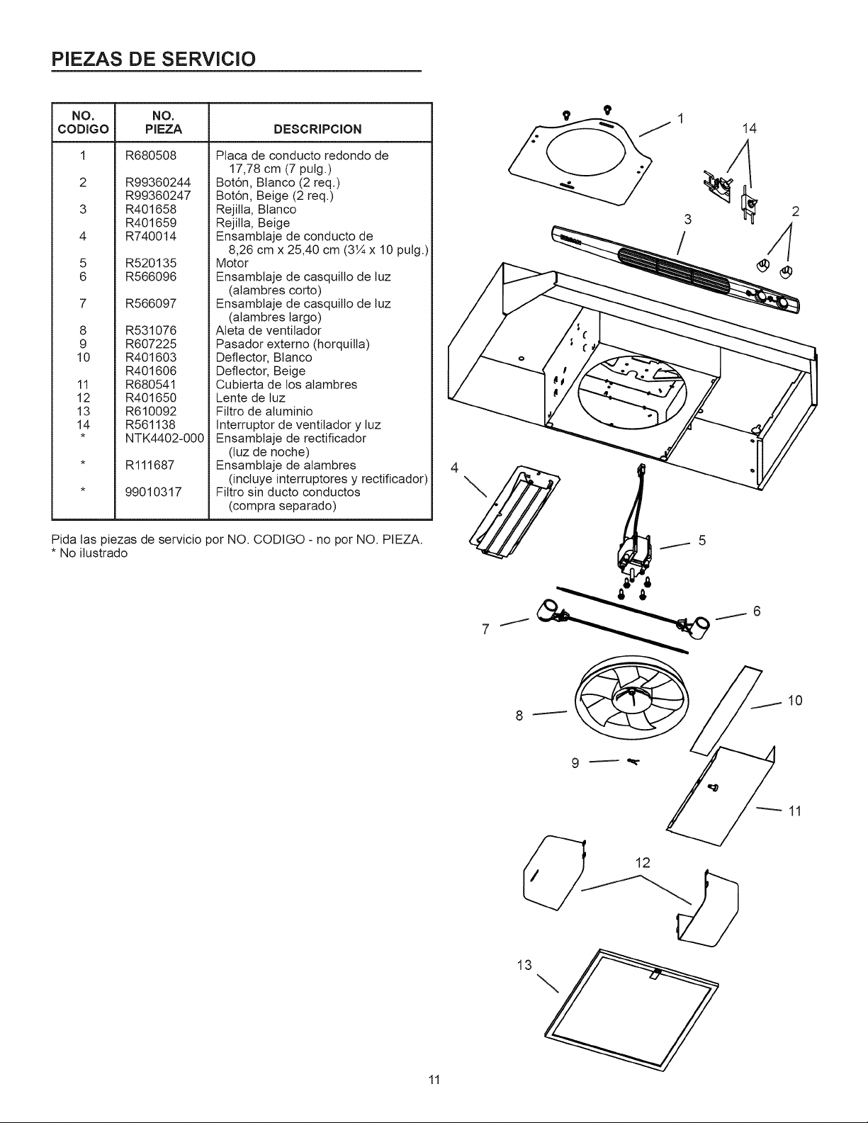
PIEZAS
DE
SERVICIO
NO.
NO.
CODIGO
PIEZA
DESGRIPCION
1
R680508
Placa
de
conducto
redondo
de
17,78
cm
(7
pulg.)
2
R99360244
Botén,
Blanco
(2
req.)
R99360247
Botén,
Beige
(2
req.)
3
R401658
Rejilla,
Blanco
R401659
Rejilla,
Beige
4
R740014
Ensamblaje
de
conducto
de
8,26
cm
x
25,40
cm
(3%
x
10
pulg.)
5
R520135
Motor
6
R566096
Ensamblaje
de
casquillo
de
luz
(alambres
corto)
7
R566097
Ensamblaje
de
casquillo
de
luz
(alambres
largo)
8
R531076
Aleta
de
ventilador
9
R607225
Pasador
externo
(horquilla)
10
R401603
Deflector,
Blanco
R401606
Deflector,
Beige
11
R680541
Cubierta
de
los
alambres
12
R401650
Lente
de
luz
13
R610092
Filtro
de
alurninio
14
R561138
Interruptor
de
ventilador
y
luz
*
NTK4402-000
|
Ensamblaje
de
rectificador
(luz
de
noche)
*
R111687
Ensamblaje
de
alambres
(incluye
interruptores
y
rectificador)
*
99010317
Filtro
sin
ducto
conductos
(compra
separado)
Pida
las
piezas
de
servicio
por
NO.
CODIGO
-
no por
NO.
PIEZA.
*
No
ilustrado
13
11
GARANTIA
GARANTIA
BROAN
LIMITADA
POR
UN
ANO
Broan
garantiza
al
consumidor
comprador
original de
sus
productos
que dichos
productos
careceran
de
defectos
en
materiales
o
en
mano
de
obra
por
un
periodo
de
un
afo
a
partir
de
la
fecha
original de
compra.
NO
EXISTEN
OTRAS
GARANTIAS,
EXPLICITAS
O
IMPLICITAS,
INCLUYENDO,
PERO
NO
LIMITADAS
A,
GARANTIAS
IMPLICITAS
DE
COMERCIALIZACION
O
APTITUD
PARA
UN
PROPOSITO
PARTICULAR.
Durante
el
periodo
de
un
afo,
y a
su
propio
criterio,
Broan
reparara
o
reemplazara,
sin
costo
alguno
cualquier
producto
o
pieza
que
se
encuentre
defectuosa
bajo
condiciones
normales
de
servicio
y
uso.
ESTA
GARANTIA
NO
SE
APLICAA
TUBOS
Y
ARRANCADORES
DE
LAMPARAS
FLUORESCENTES.
Esta
garantia
no
cubre
(a)
manitenimiento
y
servicio
normales
o
(6)
cualquier
producto
o
piezas que
hayan
sido
utilizadas
de
forma
errénea,
negligente,
que
hayan
causado
un
accidente,
o
que
hayan
sido
reparadas
o
mantenidas
inapropiadamente
(por
otras
compafiias
que
no
sean
Broan),
instalacién
defectuosa,
o
instalacioén
contraria
a
las
instrucciones
de
instalacién
recomendadas.
La
duraci6n
de
cualquier
garantia
implicita
se limita
a
un
periodo
de
un
afio
como
se
especifica
en
la
garantia
expresa.
Algunos
estados
no
permiten
limitaciones
en
cuanto
al
tiempo
de
expiracién
de
una
garantia
implicita,
por
jo
que
la
limitacién
antes
men-
cionada
puede
no
aplicarse
a
usted.
LA
OBLIGACION
DE
BROAN
DE
REPARAR
O
REEMPLAZAR,
SIGUIENDO
EL
CRITERIO
DE
BROAN,
DEBERA
SER
EL
UNICO
Y
EXCLUSIVO
RECURSO
LEGAL
DEL
COMPRADOR
BAJO
ESTA
GARANTIA.
BROAN
NO
SERA
RESPONSABLE
POR
DANOS
INCIDENTALES,
CONSIGUIENTES,
O
POR
DANOS
ESPECIALES
QUE
SURJAN
A
RAIZ
DEL
USO
O
DESEMPENO
DEL
PRO-
DUCTO.
Algunos
estados
no
permiten
la
exclusion
o
limitacién
de
dafios
incidentales
o
consiguientes,
por
lo
que
la
limitacién
antes
mencionada
puede
no
aplicarse
a
usted.
Esta
garantia
le
proporciona
derechos
legales
especificos,
y
usted
puede
también
tener
otros
derechos,
los
cuales
varian
de
estado
a
estado.
Esta
garantia
reemplaza
todas
las
garantias
anteriores.
Para
calificar
en
la
garantia
de
servicio,
usted
debe
(a)
notificar
a
la
compafiia
al
domicilio
o
al
teléfono
que
se
menciona
abajo
(b)
dar
el
numero
del
modelo
y
la
identificacién
de
la
pieza,
y
(c)
describir
la
naturaleza
de
cualquier
defecto
en
el
producto
o
pieza.
En
el
momento
de
solicitar
servicio
cubierto
por
la
garantia,
usted
debe
de
presentar
evidencia
de
la
fecha
original de
compra.
En
los
E.E.U.U.,
entre
en
contacto
con:
Broan-NuTone
LLC
Hartford,
Wisconsin
www.broan.com
800-558-1711
Los
residentes
de
Canada:
Broan-NuTone
Canada
Mississauga,
Ontario
www.broan.ca
877-896-1119
Las
especificaciones
del
producto
estan
sujetas
a
cambio
sin
previo
aviso.
Impreso
en
los
EE.UU.,
Rev.
02/08,
No
de
parte
628029B