MITSUBISHI
THE BIG SCREENCOMPANY TM
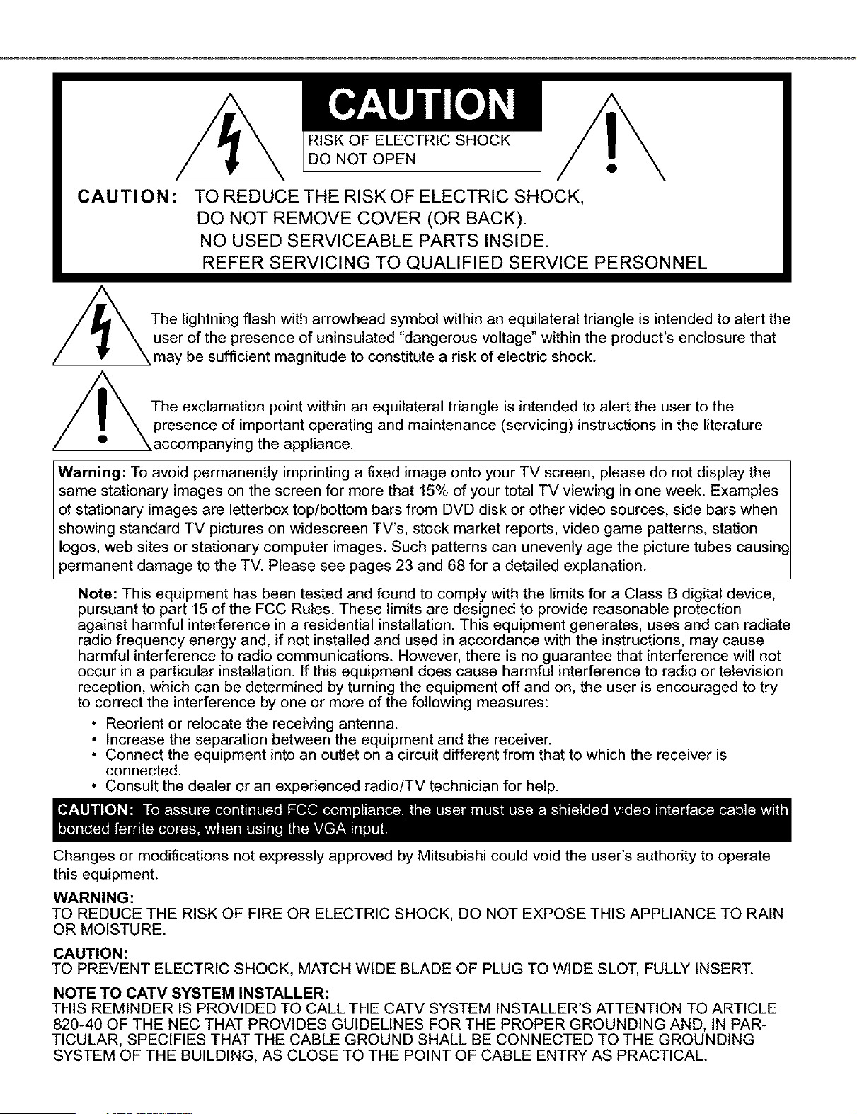
RISK OF ELECTRIC SHOCK
DO NOT OPEN
CAUTION:
TO REDUCE THE RISK OF ELECTRIC SHOCK,
DO NOT REMOVE COVER (OR BACK).
NO USED SERVICEABLE PARTS INSIDE.
REFER SERVICING TO QUALIFIED SERVICE PERSONNEL
/_The lightning flash with arrowhead symbol within an equilateral triangle is intended to alert theuser of the presence of uninsulated "dangerous voltage" within the product's enclosure that
may be sufficient magnitude to constitute a risk of electric shock.
The exclamation point within an equilateral triangle is intended to alert the user to the
presence of important operating and maintenance (servicing) instructions in the literature
\accompanying the appliance.
Warning: To avoid permanently imprinting a fixed image onto your TV screen, please do not display the
same stationary images on the screen for more that 15% of your total TV viewing in one week. Examples
of stationary images are letterbox top/bottom bars from DVD disk or other video sources, side bars when
showing standard TV pictures on widescreen TV's, stock market reports, video game patterns, station
Iogos, web sites or stationary computer images. Such patterns can unevenly age the picture tubes causing
3ermanent damage to the TV. Please see pages 23 and 68 for a detailed explanation.
Note: This equipment has been tested and found to comply with the limits for a Class B digital device,
pursuant to part 15 of the FCC Rules. These limits are designed to provide reasonable protection
against harmful interference in a residential installation. This equipment generates, uses and can radiate
radio frequency energy and, if not installed and used in accordance with the instructions, may cause
harmful interference to radio communications. However, there is no guarantee that interference will not
occur in a particular installation. If this equipment does cause harmful interference to radio or television
reception, which can be determined by turning the equipment off and on, the user is encouraged to try
to correct the interference by one or more of the following measures:
• Reorient or relocate the receiving antenna.
• Increase the separation between the equipment and the receiver.
• Connect the equipment into an outlet on a circuit different from that to which the receiver is
connected.
• Consult the dealer or an experienced radio/TV technician for help.
Changes or modifications not expressly approved by Mitsubishi could void the user's authority to operate
this equipment.
WARNING:
TO REDUCE THE RISK OF FIRE OR ELECTRIC SHOCK, DO NOT EXPOSE THIS APPLIANCE TO RAIN
OR MOISTURE.
CAUTION:
TO PREVENT ELECTRIC SHOCK, MATCH WIDE BLADE OF PLUG TO WIDE SLOT, FULLY INSERT.
NOTE TO CATV SYSTEM INSTALLER:
THIS REMINDER IS PROVIDED TO CALL THE CATV SYSTEM INSTALLER'S ATTENTION TO ARTICLE
820-40 OF THE NEC THAT PROVIDES GUIDELINES FOR THE PROPER GROUNDING AND, IN PAR-
TICULAR, SPECIFIES THAT THE CABLE GROUND SHALL BE CONNECTED TO THE GROUNDING
SYSTEM OF THE BUILDING, AS CLOSE TO THE POINT OF CABLE ENTRY AS PRACTICAL.
Table of Contents
MPORTANT SAFEGUARDS ............................................................................ 4-5
_.ppendix A: Bypassing the V-Chip Lock ........................................................................................................... 59
_.ppendix B: High De d tim Input sConnect im Corrp at il_ lity ....................................................................... 61
_.ppendix C: Remote Control Programing Codes ............................................................................................. 62
_.ppendix D: Cleaning and Service ..................................................................................................................... 63
_.ppendix E: Troubleshooting .............................................................................................................................. 64
ndex ................................................................................................................................................................. 65-66
_itsubishi Projection TV Limited Warranty ....................................................................................................... 67
1.
=
3.
Read, Retain and Follow All Instructions
Read all safety and operating instructions before operating the TV. Retain the safety and operating instructions
for future reference. Follow all operating and use instructions.
Heed Warnings
Adhere to all warnings on the appliance and in the operating instructions.
Cleaning
Unplug the TV from the walt outlet before cleaning. Do not use liquid, abrasive, or aerosol cleaners. Cleaners
can permanently damage the cabinet and screen. Use a lightly dampened cloth for cleaning.
4, Attachments and Equipment
Never add any attachments and/or equipment without approval of the manufacturer as such additions may
result in the risk of r_ d e_tricshock or ct her personal ir_u_y.
5, Water and Moisture
Do not use the TV where contact with or immersion in water is possible. Do not use near bath tubs, wash
bowls, kitchen sinks, laundry tubs, swimming pools, etc.
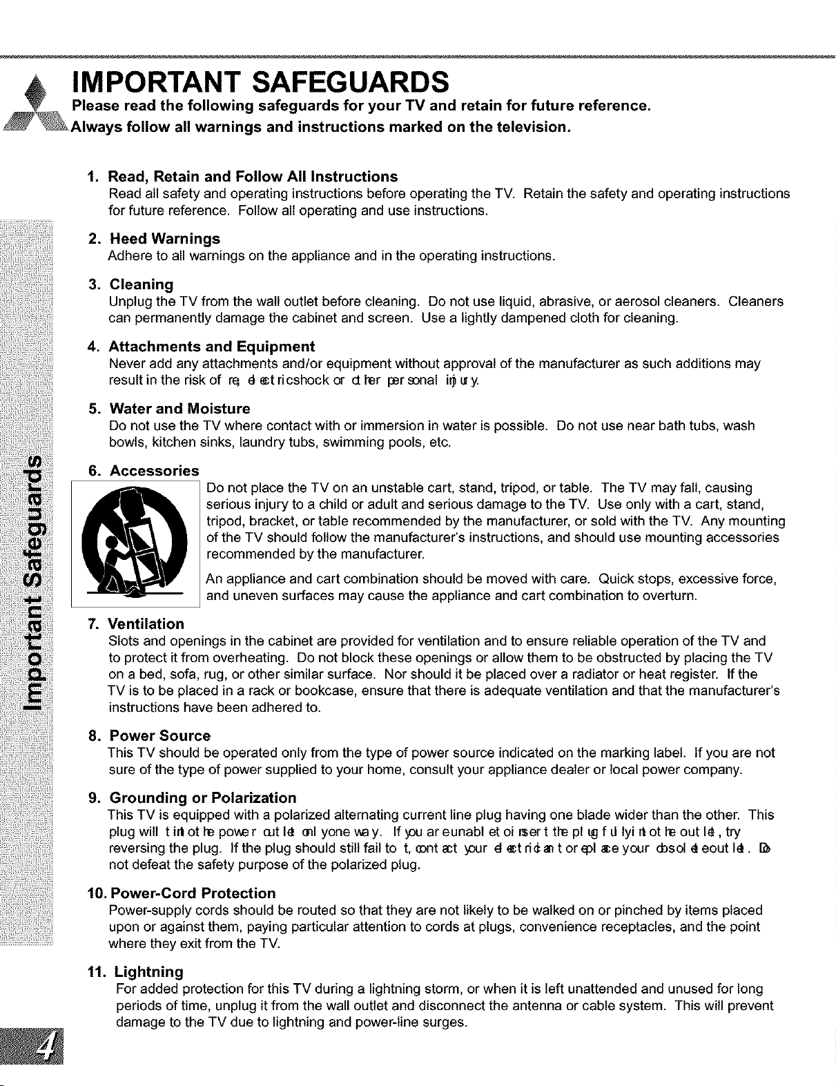
6. Accessories
Do not place the TV on an unstable cart, stand, tripod, or table. The TV may fall, causing
serious injury to a child or adult and serious damage to the TV. Use only with a cart, stand,
tripod, bracket, or table recommended by the manufacturer, or sold with the TV. Any mounting
of the TV should follow the manufacturer's instructions, and should use mounting accessories
recommended by the manufacturer.
An appliance and cart combination should be moved with care. Quick stops, excessive force,
and uneven surfaces may cause the appliance and cart combination to overturn.
=
Ventilation
Slots and openings in the cabinet are provided for ventilation and to ensure reliable operation of the TV and
to protect it from overheating. Do not block these openings or allow them to be obstructed by placing the TV
on a bed, sofa, rug, or other similar surface. Nor should it be placed over a radiator or heat register. If the
TV is to be placed in a rack or bookcase, ensure that there is adequate ventilation and that the manufacturer's
instructions have been adhered to.
8, Power Source
This TV should be operated only from the type of power source indicated on the marking label. If you are not
sure of the type of power supplied to your home, consult your appliance dealer or local power company.
g.
Grounding or Polarization
This TV is equipped with a polarized alternating current line plug having one blade wider than the other. This
plug wilt t irt ot he power cut I_ ml yone way. If _ou ar eunabl et oi r$er t the pl _gf d lyi _ ot heout I_, try
reversing the plug. If the plug should still fail to t, _nt act y_ur d e:t d_ an t or epl _e your d_sol _ eout l_.
not defeat the safety purpose of the polarized plug.
10, Power-Cord Protection
Power-supply cords should be routed so that they are not likely to be walked on or pinched by items placed
upon or against them, paying particular attention to cords at plugs, convenience receptacles, and the point
where they exit from the TV.
11.
Lightning
For added protection for this TV during a lightning storm, or when it is left unattended and unused for long
periods of time, unplug it from the wall outlet and disconnect the antenna or cable system. This will prevent
damage to the TV due to lightning and power-line surges.
IMPORTANT SAFEGUARDS Continued
12.
13.
Power Lines
An outside antenna system should not be located in the vicinity of overhead power lines or other electric light
or power circuits, or where it can fall into such power lines or circuits. When installing an outside antenna
system, extreme care should be taken to keep from touching such power lines or circuits as contact with
them might be fatal.
Overloading
Do not overload walt outlets and extension cords as this can result in a risk of reor d e:t dcshock.
14.
15.
16.
17.
Object and Liquid Entry
Never push objects of any kind into this TV through openings as they may touch dangerous voltage points or
short-out parts that could result in reor d e:t dcshock, h_ver spi 1tli_i dof any ki _ on or i_ ot heTV.
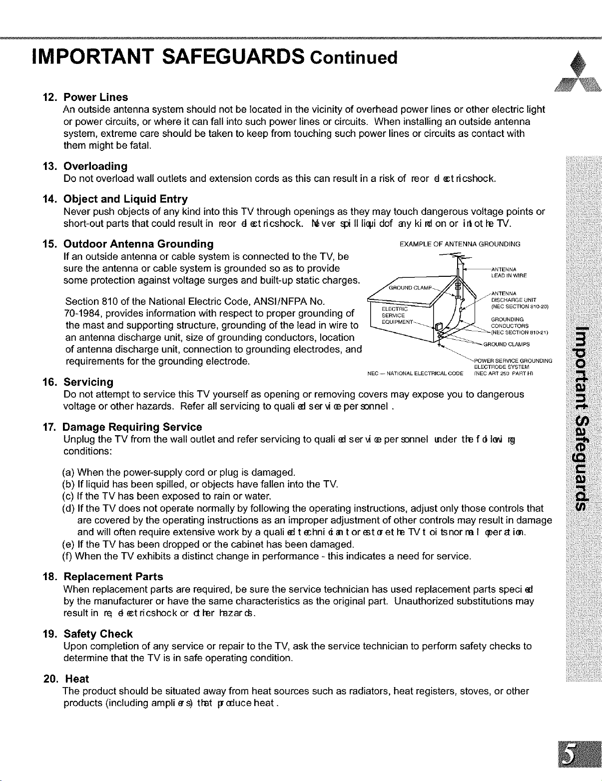
Outdoor Antenna Grounding
If an outside antenna or cable system is connected to the TV, be
sure the antenna or cable system is grounded so as to provide
some protection against voltage surges and built-up static charges.
Section 810 of the National Electric Code, ANSI/NFPA No.
70-1984, provides information with respect to proper grounding of
the mast and supporting structure, grounding of the lead in wire to
an antenna discharge unit, size of grounding conductors, location
of antenna discharge unit, connection to grounding electrodes, and
requirements for the grounding electrode.
EXAMPLE OF ANTENNA GROUNDING
.ANTENNA
(NEC SECTION 810-20)
GROUNDING
CONDUCTORS
}
_GROUND CLAMPS
_POWER SERVICE GROUNDING
ELECTRODE SYSTEM
NEC _-- NATIONAL ELECTRICAL CODE INEC ART 250 PART HI
Servicing
Do not attempt to service this TV yourself as opening or removing covers may expose you to dangerous
voltage or other hazards. Refer all servicing to quail edser vi _ per sonnel.
Damage Requiring Service
Unplug the TV from the wall outlet and refer servicing to quail edser vi _ per sonnel under the f d_l_
conditions:
18.
(a) When the power-supply cord or plug is damaged.
(b) If liquid has been spilled, or objects have fallen into the TV.
(c) If the TV has been exposed to rain or water.
(d) If the TV does not operate normally by following the operating instructions, adjust only those controls that
are covered by the operating instructions as an improper adjustment of other controls may result in damage
and will often require extensive work by a quail ed t echni _ an t or est • et heTV t oi tsnor ra 1 q_er_t iun.
(e) If the TV has been dropped or the cabinet has been damaged.
(f) When the TV exhibits a distinct change in performance - this indicates a need for service.
Replacement Parts
When replacement parts are required, be sure the service technician has used replacement parts speci ed
by the manufacturer or have the same characteristics as the original part. Unauthorized substitutions may
resultin r_ de:tdcshockor ether hazards.
19. Safety Check
Upon completion of any service or repair to the TV, ask the service technician to perform safety checks to
determine that the TV is in safe operating condition.
20. Heat
The product should be situated away from heat sources such as radiators, heat registers, stoves, or other
products (including ampli e s) that p"educe heat.


Part I: Thank You
e at Mitsubishi Would Like to Thank You
To the Mitsubishi Consumer:
Thank you for choosing Mitsubishi as your premier home
entertainment partner. Whether this is your rst M tsubi s_i
consumer electronics product or an addition to your growing
Mitsubishi family, you should be proud and delighted for
choosing one of the most technologically advanced bigscreens
available today.
Unlike typical television manufacturers, we have based our
primary design and engineering capabilities in North America
at our California headquarters. As a result, the engineers who
design our television products live in the same communities
as our customers. They know how our customers think and
what their goals and desires are. They know that today's
consumer has never been more sophisticated and that the
way to reach that consumer is to deliver technically advanced
products at prices that our competition simply can't match.
When you look at your new Mitsubishi bigscreen television,
please see all of us who built it, because when we build it, we
see you.
Thank You Again,
The Mitsubishi Team
Partl:Thank You
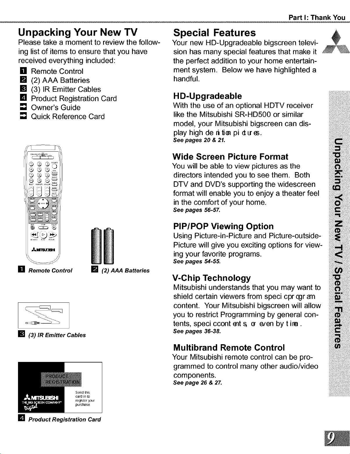
Unpacking Your New TV
Please take a moment to review the follow-
ing list of items to ensure that you have
received everything included:
[] Remote Control
[] (2) AAA Batteries
[] (3) IR Emitter Cables
[] Product Registration Card
[] Owner's Guide
[] Quick Reference Card
Q®Q ....
QQ
[] Remote Control [] (2) AAA Batteries
[] (3) IR Emitter Cables
Send this
cald in
registeryour
pulchase
Special Features
Your new HD-Upgradeable bigscreen televi-
sion has many special features that make it
the perfect addition to your home entertain-
ment system. Below we have highlighted a
handful.
H D-Upgradeable
With the use of an optional HDTV receiver
like the Mitsubishi SR-HD500 or similar
model, your Mitsubishi bigscreen can dis-
p,ayhighde.U pi Seepages,O, ,.
Wide Screen Picture Format
You will be able to view pictures as the
directors intended you to see them. Both
DTV and DVD's supporting the widescreen
formatwillenableyoutoenjoyatheaterfee,
in the comfort of your home.
Seepages 56-57.
PIP/POPViewing Option
usingPicture-in-PictureandPicture-outside-
Picturewillgiveyouexcitingoptionsforview-
ing yourfavorite programs.
Seepages,,-55.
V-Chip Technology
Mitsubishiunderstandsthatyoumaywantto
shield certain viewersfrom speci cpregran
content. Your Mitsubishi bigscreen will allow
youtorestrictProgrammingbygeneralcon-
tents, speci ccontmts ar e/en by tire.
See pages 36-38.
Multibrand Remote Control
Your Mitsubishi remote control can be pro-
grammed to control many other audio/video
components.
See page 26 & 27.
[] Product Registration Card

Part I1: Installation
Front Control Panel
(M_NO)
S V_EO VIDEO L-AUblO
INPor 4
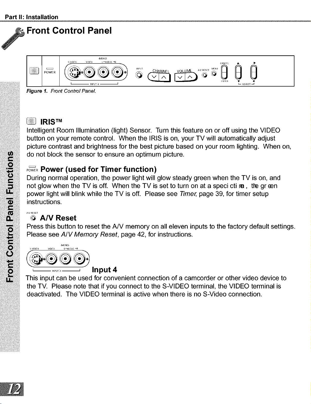
Figure 1. Front Control Panel.
......Oo
@
ENrEI_ •
u- AbJUSq _
IRIS TM
Intelligent Room Illumination (light) Sensor. Turn this feature on or off using the VIDEO
button on your remote control. When the IRIS is on, your TV will automatically adjust
picture contrast and brightness for the best picture based on your room lighting. When on,
do not block the sensor to ensure an optimum picture.
Pow%,Power (used for Timer function)
During normal operation, the power light will glow steady green when the TV is on, and
not glow when the TV is off. When the TV is set to turn on at a speci cti re, the green
power light will blink while the TV is off. Please see Timer, page 39, for timer setup
instructions.
AN_SE[
@ A/V Reset
Press this button to reset the A/V memory on all eleven inputs to the factory default settings.
Please see A/V Memory Reset, page 42, for instructions.
(MONO)
S VID£O V_DE0 L -AUDIO -_
L ........ J Input 4
This input can be used for convenient connection of a camcorder or other video device to
the TV. Please note that if you connect to the S-VIDEO terminal, the VIDEO terminal is
deactivated. The VIDEO terminal is active when there is no S-Video connection.
Part I1: Installation
Back Panel
mm
@
®
®
B-
®®
®®
® ®®
® ®®
®
®®"
®
®
_R E_TTER HOME THEATER
®®®_
J
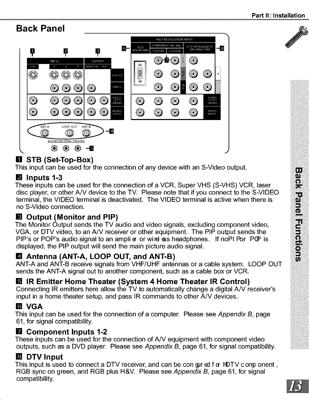
[] STB (Set-Top-Box)
This input can be used for the connection of any device with an S-Video output.
[] Inputs 1-3
These inputs can be used for the connection of a VCR, Super VHS (S-VHS) VCR, laser
disc player, or other A/V device to the TV. Please note that if you connect to the S-VIDEO
terminal, the VIDEO terminal is deactivated. The VIDEO terminal is active when there is
no S-Video connection.
[] Output (Monitor and PIP)
The Monitor Output sends the TV audio and video signals, excluding component video,
VGA, or DTV video, to an A/V receiver or other equipment. The PIP output sends the
PIP's or POP's audio signal to an ampli • or wiEI _s headphones. If noPI Por P(]? is
displayed, the PIP output will send the main picture audio signal.
[] Antenna (ANT-A, LOOP OUT, and ANT-B)
ANT-A and ANT-B receive signals from VHF/UHF antennas or a cable system. LOOP OUT
sends the ANT-A signal out to another component, such as a cable box or VCR.
[] IR Emitter Home Theater (System 4 Home Theater IR Control)
Connecting IR emitters here allow the TV to automaticallychange a digital A/V receiver's
input in a home theater setup, and pass IR commands to other A/V devices.
[] VGA
This input can be used for the connection of a computer. Please see Appendix B, page
61, for signal compatibility.
[] Component Inputs 1-2
These inputs can be used for the connection of A/V equipment with component video
outputs, such as a DVD player. Please see Appendix B, page 61, for signal compatibility.
[] DTV Input
This input is used to connect a DTV receiver, and can be con _r ed far I-DTV corrp orient,
RGB sync on green, and RGB plus H&V. Please see Appendix B, page 61, for signal
compatibility.
Part I1: Installation
How Connections Affect the PIP and POP
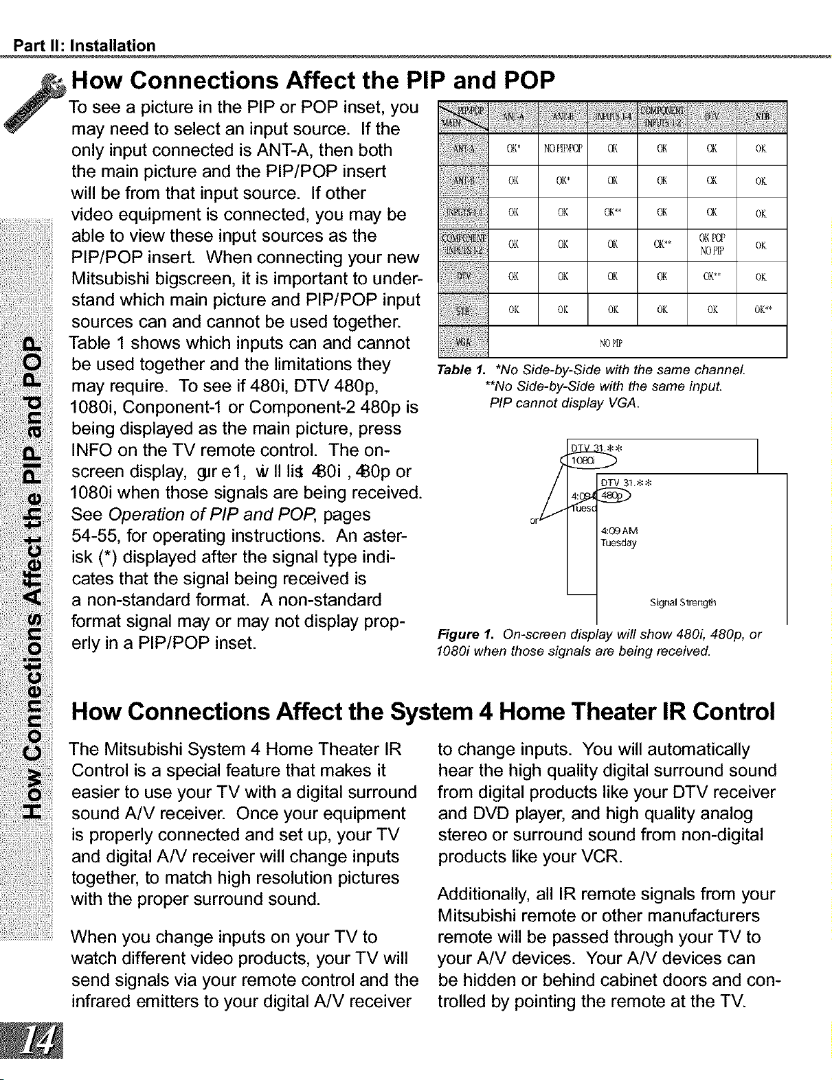
To see a picture in the PIP or POP inset, you
may need to select an input source. If the
only input connected is ANT-A, then both oK No_oP ox oK oK oK
the main picture and the PIP/POP insert
OK OK* OK OK OK OK
will be from that input source. If other
video equipment is connected, you may be oK oK oK oK oK oK
able to view these input sources as the oK* oKPoP
PIP/POP insert. When connecting your new oK oK oK Nop_P oK
Mitsubishi bigscreen, it is important to under- V oK oK oK oK oK,* oK
stand which main picture and PIP/POP input oK oK oK oK oK oK,,
sources can and cannot be used together. .............................................
Table 1 shows which inputs can and cannot No_,,_
be used together and the limitations they Table 1. *NoSide-by-Sidewiththe same channel.
may require. To see if 480i, DTV 480p, **NoSide-by-Sidewiththe same input.
1080i, Conponent-1 or Component-2 480p is Pip cannotdisplayVGA.
being displayed as the main picture, press
INFO on the TV remote control. The on- _ _* 1
screen display, _r e 1, * II li_ zB0i, zB0p or / DTV3_.**
1080i when those signals are being received. _.. _
See Operation of PIP and POP, pages or
54-55, for operating instructions. An aster- 4:_AM
Tuesday
isk (*) displayed after the signal type indi-
cates that the signal being received is
a non-standard format. A non-standard -- s_9o_,s_e_
format signal may or may not display prop-
Figure 1. On-screen display will show 480i, 480p, or
erly in a PIP/POP inset, lo8oi when those signalsarebeingreceived.
How Connections Affect the System 4 Home Theater IR Control
The Mitsubishi System 4 Home Theater IR to change inputs. You will automatically
Control is a special feature that makes it hear the high quality digital surround sound
easier to use your TV with a digital surround from digital products like your DTV receiver
sound A/V receiver. Once your equipment and DVD player, and high quality analog
is properly connected and set up, your TV stereo or surround sound from non-digital
and digital A/V receiver will change inputs products like your VCR.
together, to match high resolution pictures
with the proper surround sound. Additionally, all IR remote signals from your
Mitsubishi remote or other manufacturers
...........................When you change inputs on your TV to remote will be passed through your TV to
watch different video products, your TV will your A/V devices. Your A/V devices can
send signals via your remote control and the be hidden or behind cabinet doors and con-
infrared emitters to your digital A/V receiver trolled by pointing the remote at the TV.
Part I1: Installation
Special Setups: A/V Equipment (For System 4 Home Theater IR Control)
VCR: Connect the cables to the TV as
directed on page 17, with one exception.
Connect the audio output connection to the
appropriate input on the back of the A/V
receiver (as shown in table 1).
DVD: Connect the cables as directed on
page 19 (using the COMPONENT-1 input),
with one exception. Connect the digital
audio output connection on the DVD player
to the appropriate digital input on the back
of the digital A/V receiver (as shown in table
1).
•Auto Standby: ON (See your A/V receiver's
Owner's Guide for this procedure). For all TV
use, the sound will come from the A/V receiver.
Not available with all A/V receivers.
•Digital Input Assignment for DVD: Assign the
digital input you used for your DVD player to the
A/V receiver's DVD input selector. This proce-
dure is explained in your A/V receiver's Owner's
Guide.
•Digital Assignment for DTV: Assign the digital
input you used for DTV to the A/V receiver's DTV
input selector.
Infrared Emitter: Connect as shown on
page 22.
DTV: Connect the cables as directed on
pages 20-21, with one exception. Connect
the digital audio output connection on the
DTV receiver to the appropriate digital input
on the back of the digital A/V receiver (as
shown in table 1).
A/V Receiver: Connect as directed on
page 18, with two additions. Use a S-Video
cable in step 1 if you have a S-Video VCR.
The TV outputs should be connected to the
A/V receivers input marked TV.
Special Setups: TV
Menu selection for A/V connections, page 32.
•TV Speakers: OFF
•Audio Output: Fixed
•TV Inputs Appropriately Named: See Assign
Input Menu, page 33.
Remote Control, pages 26-27.
•Set the slide switch to the TV position and follow
the programming instructions using the A/V
receiver code appropriate for your A/V receiver,
page 27 (_re5).
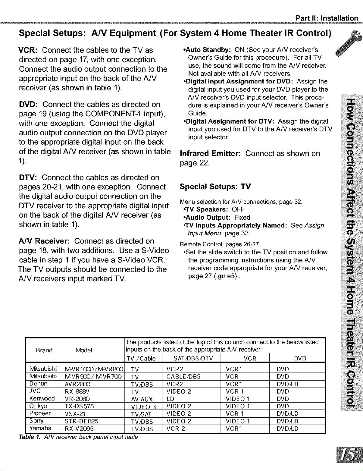
Brand Model
The products listed at_he tDp of_his column connectlD _he belowlist_d
inputs on _he back of_he
TV/Cable
appropfiae AN receiver.
SAT/DBS/DTV VCR
DVD
IVHtsubishi M-VRIO00/M-VRSO0 TV VCR2 VCR1 DVD
IVHtsubsihi M-VR£O0/M-VR700 TV CABLE/DBS VCR DVD
Denon AVR2800 TV/DBS VCR2 VCR1 DVD/LD
JVC RX-888V TV VIDEO 2 VCR 1 DVD
Kenwood VR-2080 AV AUX LD VIDEO 1 DVD
Onkyo TX-DS575 VIDEO 3 VIDEO 2 VIDEO 1 DVD
Pioneer VSX-21 TV/SAT VIDEO 2 VCR 1 DVD/LD
Sony STR-DE825 TV/DBS VIDEO 2 VIDEO 1 DVD/LD
Yamaha RX-V2095 TV/DBS VCR 2 VCR1 DVD/LD
Table I. A/V receiver back panel input table
Part I1: Installation
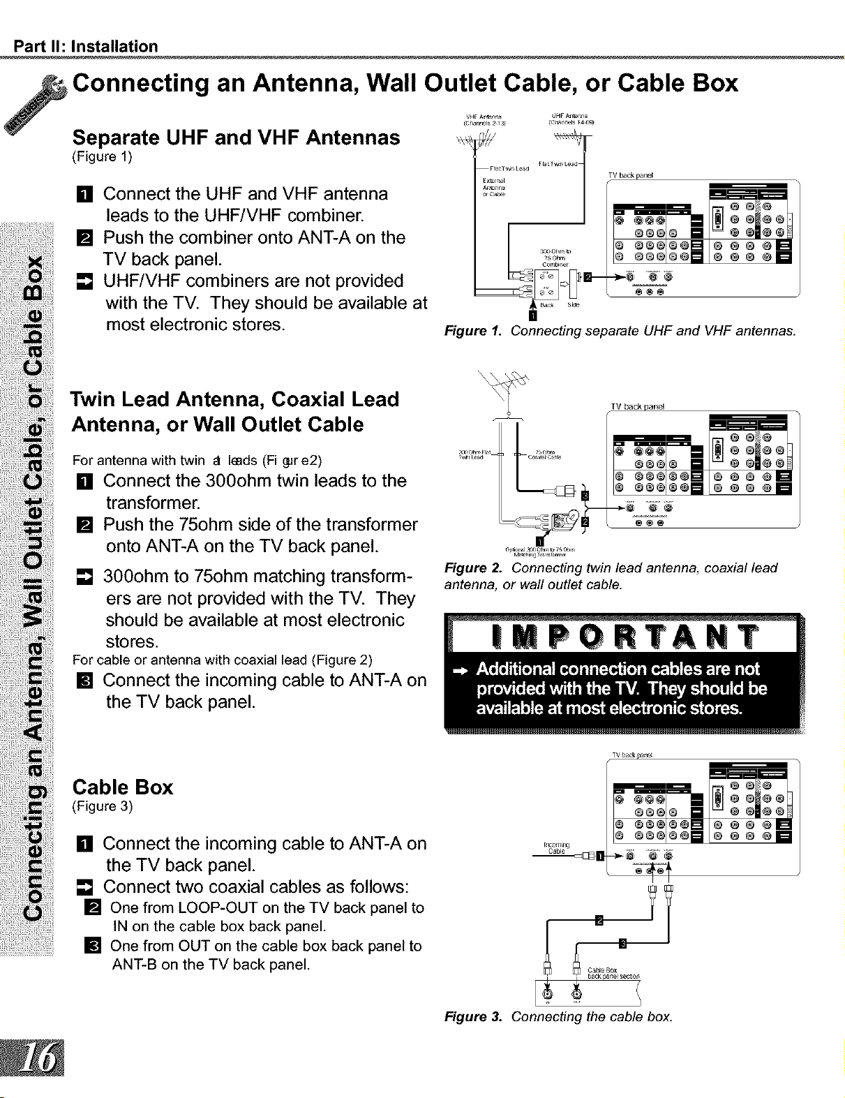
Connecting an Antenna, Wall Outlet Cable, or Cable Box
Separate UHF and VHF Antennas
(Figure 1)
[] Connect the UHF and VHF antenna
leads to the UHF/VHF combiner.
[] Push the combiner onto ANT-A on the
TV back panel.
[] UHF/VHF combiners are not provided
with the TV. They should be available at
most electronic stores.
VHF A_l_lr_ UH_ A_r _la
G _8_GG_i ® g _ _1_
_og_GD _ e_ _m
sa_ Side
Figure 1. Connecting separate UHF and VHF antennas.
Twin Lead Antenna, Coaxial Lead
Antenna, or Wall Outlet Cable
For antenna with twin _t Imds (Fi gpre2)
[] Connect the 300ohm twin leads to the
transformer.
[] Push the 75ohm side of the transformer
onto ANT-A on the TV back panel.
[] 300ohm to 75ohm matching transform-
ers are not provided with the TV. They
should be available at most electronic
stores.
For cable or antenna with coaxial lead (Figure 2)
[] Connect the incoming cable to ANT-A on
the TV back panel.
op_on_l _ot_ _ 7_ohm
Figure 2. Connecting twin lead antenna, coaxial lead
antenna, or wall outlet cable.
TV back paI_l
Cable Box
(Figure 3)
[] Connect the incoming cable to ANT-A on
the TV back panel.
[] Connect two coaxial cables as follows:
[] One from LOOP-OUT on the TV back panel to
IN on the cable box back panel.
[] One from OUT on the cable box back panel to
ANT-B on the TV back panel.
rn_lng
C_ble
[]
TV back pane_
Cable Box
Figure 3. Connecting the cable box.
Part I1: Installation
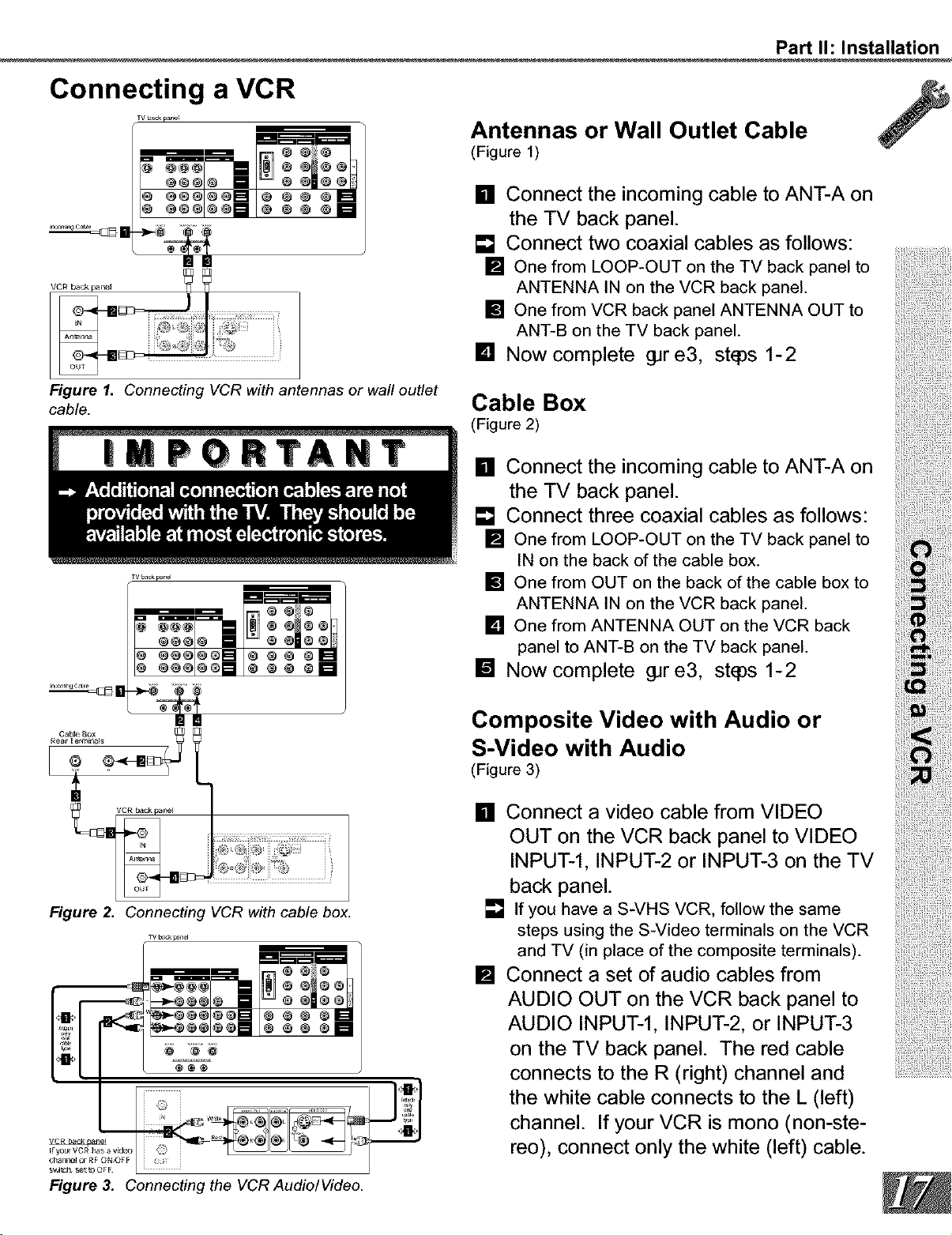
Connecting a VCR
v bac< p_r
o÷el®_[] o ® e ®1_
_e_l®_ [] o ®e ®E
Antennas or Wall Outlet Cable
(Figure 1)
[] Connect the incoming cable to ANT-A on
the TV back panel.
[] Connect two coaxial cables as follows:
[] One from LOOP-OUT on the TV back panel to
ANTENNA IN on the VCR back panel.
[] One from VCR back panel ANTENNA OUT to
ANT-B on the TV back panel.
[] Now complete gJre3, st_ps 1-2
Figure I. Connecting VCR with antennas or wall outlet
cable.
Cable Box
(Figure 2)
[] Connect the incoming cable to ANT-A on
the TV back panel.
[] Connect three coaxial cables as follows:
[] One from LOOP-OUT on the TV back panel to
IN on the back of the cable box.
[] One from OUT on the back of the cable box to
ANTENNA IN on the VCR back panel.
[] One from ANTENNA OUT on the VCR back
panel to ANT-B on the TV back panel.
[] Now complete gJre3, st_ps 1-2
Composite Video with Audio or
S-Video with Audio
(Figure 3)
Figure 2. Connecting VCR with cable box.
TV b,_k panel
[] Connect a video cable from VIDEO
OUT on the VCR back panel to VIDEO
INPUT-l, INPUT-2 or INPUT-3 on the TV
back panel.
[] If you have a S-VHS VCR, follow the same
steps using the S-Video terminals on the VCR
and TV (in place of the composite terminals).
[] Connect a set of audio cables from
AUDIO OUT on the VCR back panel to
AUDIO INPUT-l, INPUT-2, or INPUT-3
on the TV back panel. The red cable
connects to the R (right) channel and
the white cable connects to the L (left)
channel. If your VCR is mono (non-ste-
reo), connect only the white (left) cable.
Figure 3. Connecting the VCR Audio/Video.
Part I1: Installation
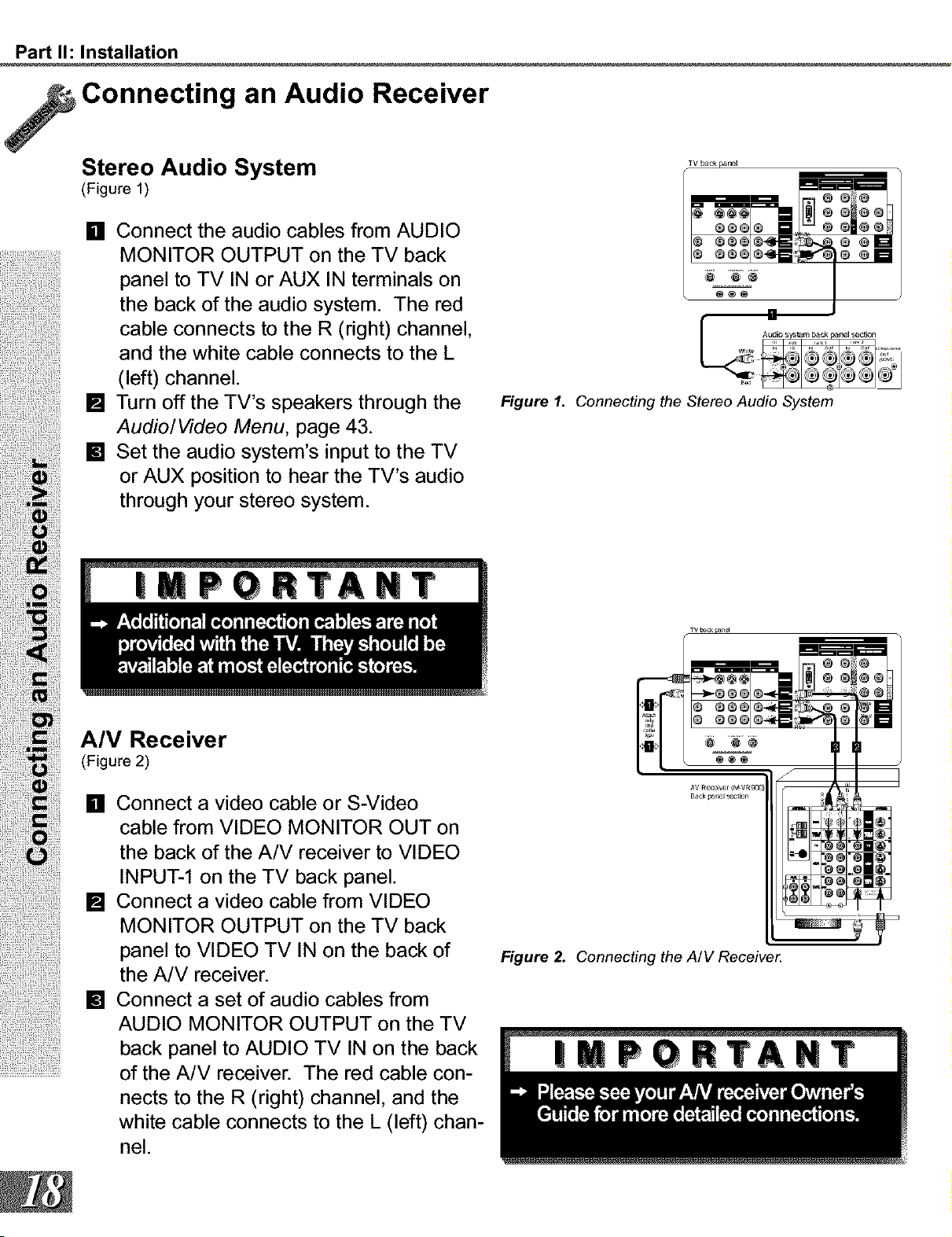
Connecting an Audio Receiver
Stereo Audio System
(Figure 1)
[] Connect the audio cables from AUDIO
MONITOR OUTPUT on the TV back
panel to TV IN or AUX IN terminals on
the back of the audio system. The red
cable connects to the R (right) channel,
and the white cable connects to the L
(left) channel.
[] Turn off the TV's speakers through the
Audio/Video Menu, page 43.
[] Set the audio system's input to the TV
or AUX position to hear the TV's audio
through your stereo system.
TV back #_nel
Figure 1. Connecting the Stereo Audio System
A/V Receiver
(Figure 2)
[] Connect a video cable or S-Video
cable from VIDEO MONITOR OUT on
the back of the A/V receiver to VIDEO
INPUT-1 on the TV back panel.
[] Connect a video cable from VIDEO
MONITOR OUTPUT on the TV back
panel to VIDEO TV IN on the back of
the A/V receiver.
[] Connect a set of audio cables from
AUDIO MONITOR OUTPUT on the TV
back panel to AUDIO TV IN on the back
of the A/V receiver. The red cable con-
nects to the R (right) channel, and the
white cable connects to the L (left) chan-
nel.
Figure 2. Connecting the A/V Receive_
Part I1: Installation
WARNING:
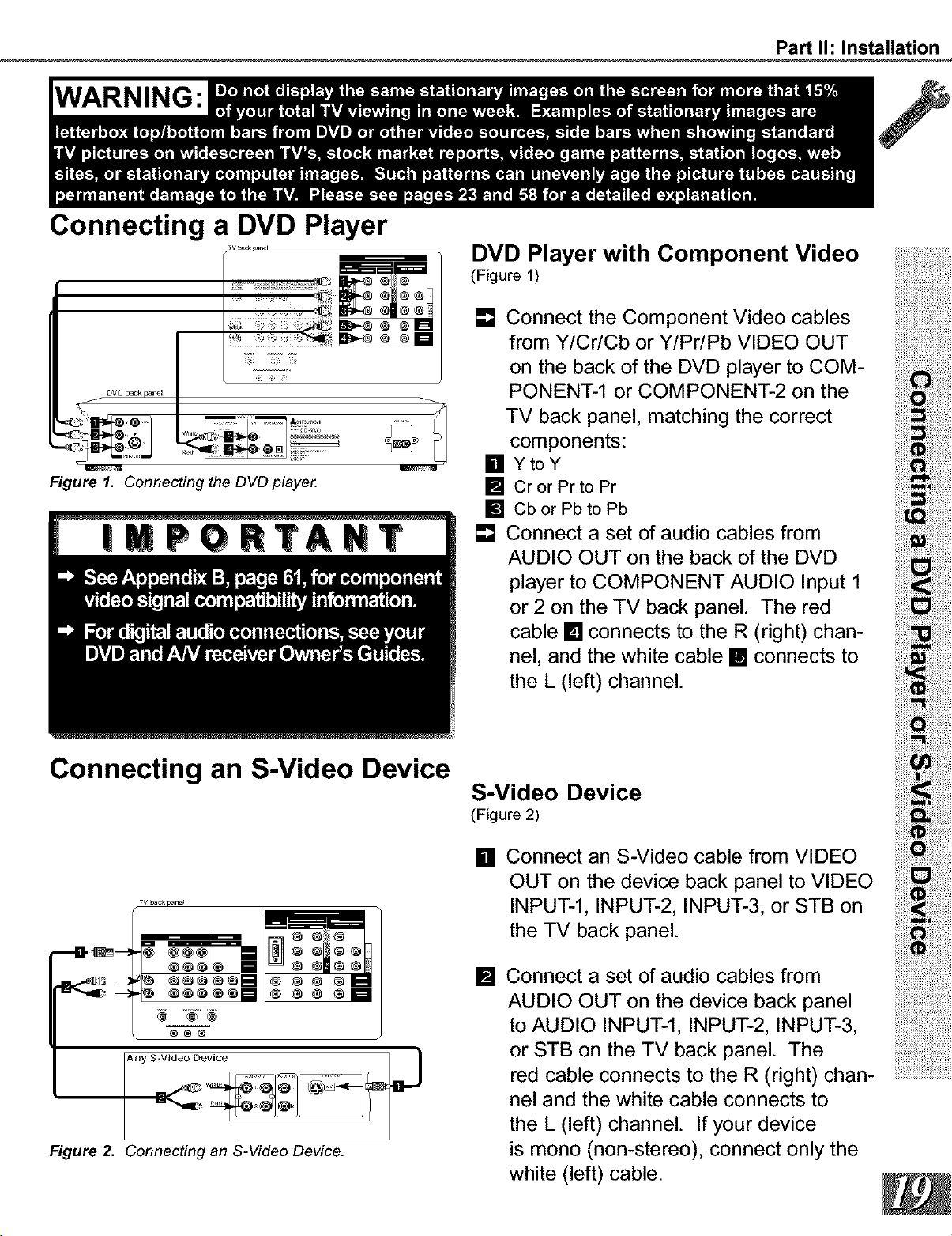
Connecting a DVD Player
TV _s_ _I
_iiil:;ii_"_i_!ii¸
DVD back p,_nel
/
U
Figure I. Connecting the DVD playe_
Connecting an S-Video Device
TV ba_ p_ne_
@@®
Figure 2. Connecting an S-Video Device.
DVD Player with Component Video
(Figure 1)
[] Connect the Component Video cables
from Y/Cr/Cb or Y/Pr/Pb VIDEO OUT
on the back of the DVD player to COM-
PONENT-1 or COMPONENT-2 on the
TV back panel, matching the correct
components:
[] Y to Y
[] CrorPrtoPr
[] CborPbtoPb
[] Connect a set of audio cables from
AUD,OOUTonthebackoftheDVD
player to COMPONENT AUDIO Input 1
or 2 on the TV back panel. The red
cable [] connects to the R (right) chan-
thenel'Land(left)thechannel.whitecable [] connects to
S-Video Device
(Figure 2)
[] Connect an S-Video cable from VIDEO
OUT on the device back panel to VIDEO
INPUT-l, INPUT-2, INPUT-3, or STB on
the TV back panel.
[] Connect a set of audio cables from
AUDIO OUT on the device back panel
to AUDIO INPUT-l, INPUT-2, INPUT-3,
or STB on the TV back panel. The
red cable connects to the R (right) chan .....................................
nel and the white cable connects to
the L (left) channel. If your device
is mono (non-stereo), connect only the
white (left) cable.
Part I1: Installation
Connecting a DTV Receiver
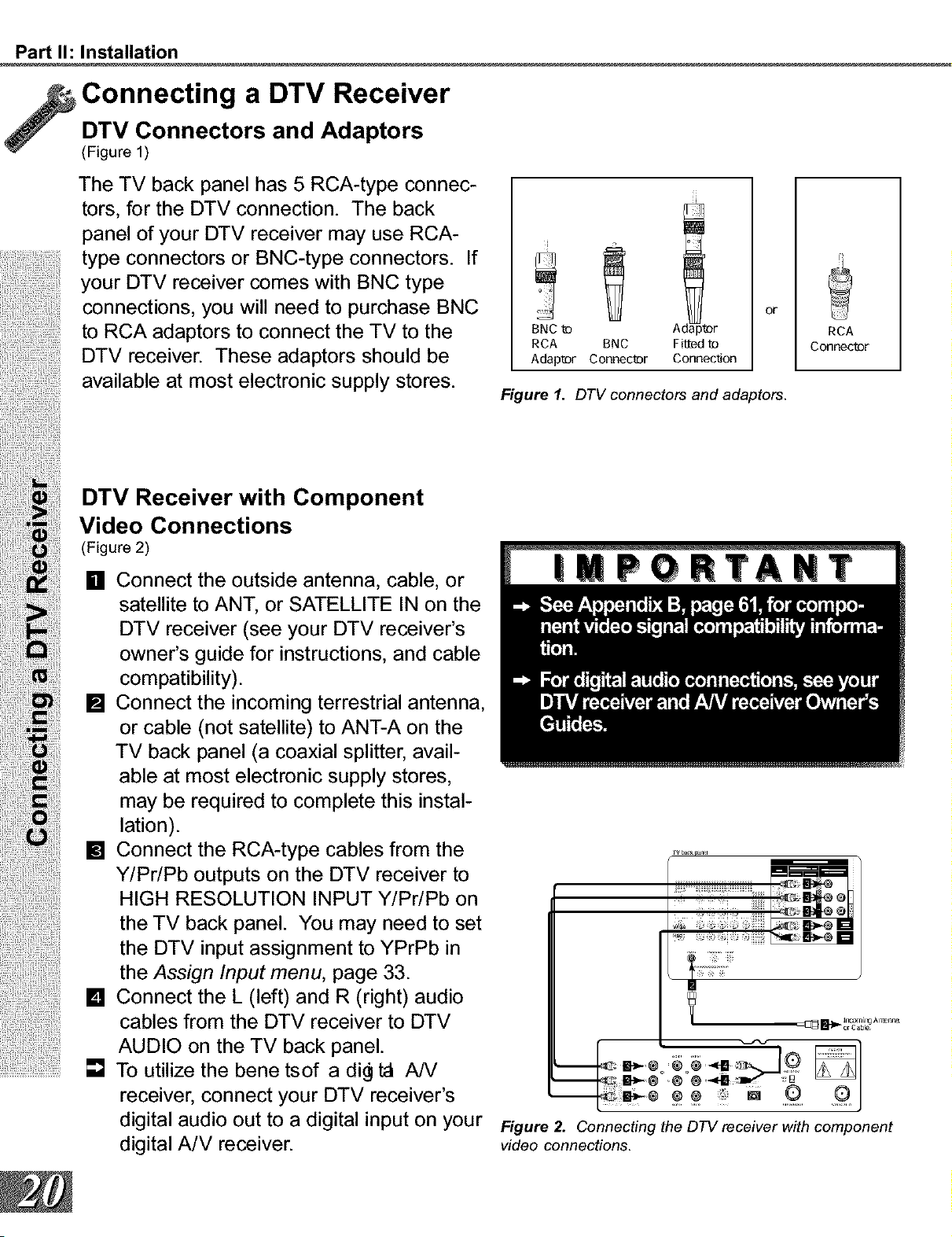
DTV Connectors and Adaptors
(Figure 1)
The TV back panel has 5 RCA-type connec-
tors, for the DTV connection. The back
panel of your DTV receiver may use RCA-
type connectors or BNC-type connectors. If
your DTV receiver comes with BNC type
connections, you will need to purchase BNC
to RCA adaptors to connect the TV to the
DTV receiver. These adaptors should be
available at most electronic supply stores.
BNC _ A r
RCA BNC Find t_
Adapt_r Connec_r Connection
or
Figure 1. DTV connectors and adaptors.
RCA
Connec_r
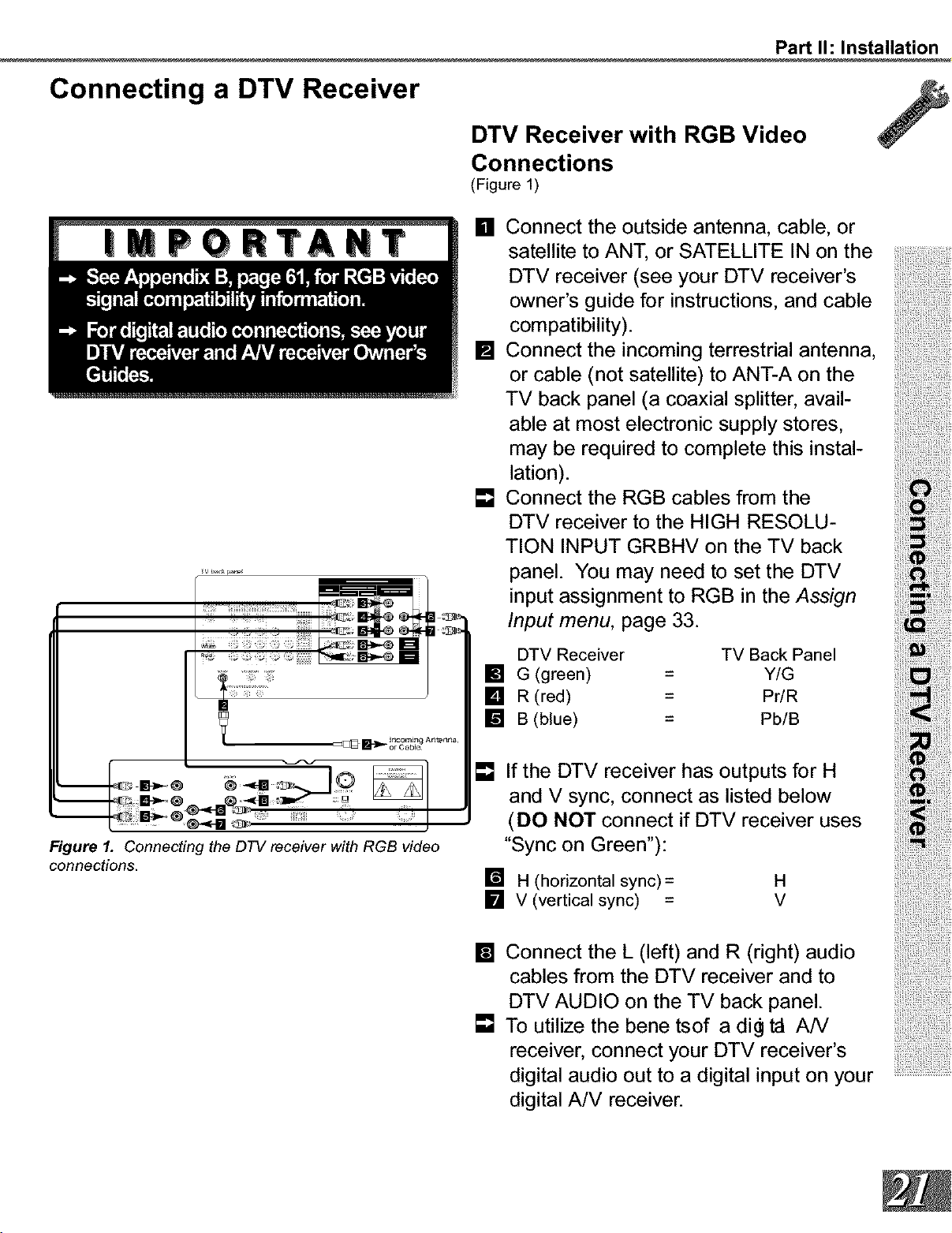
DTV Receiver with Component
Video Connections
(Figure 2)
........................... ]
[] Connect the outside antenna, cable, or
satellite to ANT, or SATELLITE IN on the
DTV receiver (see your DTV receiver's
owner's guide for instructions, and cable
compatibility).
[] Connect the incoming terrestrial antenna,
or cable (not satellite) to ANT-A on the
TV back panel (a coaxial splitter, avail-
able at most electronic supply stores,
may be required to complete this instal-
lation).
[] Connect the RCA-type cables from the
Y/Pr/Pb outputs on the DTV receiver to
HIGH RESOLUTION INPUT Y/Pr/Pb on
the TV back panel. You may need to set
the DTV input assignment to YPrPb in
the Assign Input menu, page 33.
[] Connect the L (left) and R (right) audio
cables from the DTV receiver to DTV
AUDIO on the TV back panel.
To utilize the bene tsof a di_ ta AN
receiver, connect your DTV receiver's
digital audio out to a digital input on your
digital A/V receiver.
v baca_l_l
_or Cable
Figure 2. Connecting the DTV receiver with component
video connections.
Part I1: Installation
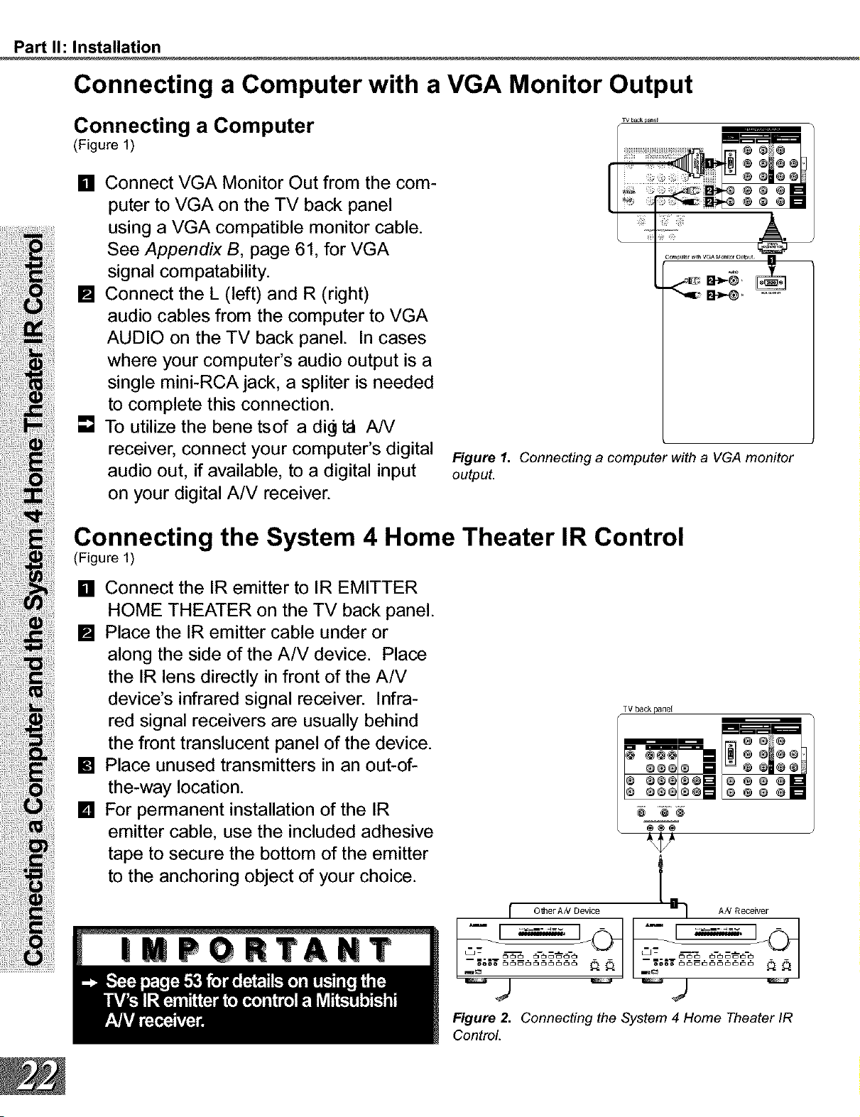
Connecting a DTV Receiver
DTV Receiver with RGB Video
Connections
(Figure 1)
!!iii¸¸iiiiiiii
|_
Inc°mi_ Antenna
Figure I. Connecting the DTV receiver with RGB video
connections.
[] Connect the outside antenna, cable, or
satellite to ANT, or SATELLITE IN on the
DTV receiver (see your DTV receiver's
owner's guide for instructions, and cable
compatibility).
[] Connect the incoming terrestrial antenna,
or cable (not satellite) to ANT-A on the
TV back panel (a coaxial splitter, avail-
able at most electronic supply stores,
may be required to complete this instal-
lation).
[] Connect the RGB cables from the
DTV receiver to the HIGH RESOLU-
TION INPUT GRBHV on the TV back
panel. You may need to set the DTV
input assignment to RGB in the Assign
Input menu, page 33.
DTV Receiver TV Back Panel
[] G (green) = Y/G
[] R (red) = Pr/R
[] B (blue) = Pb/B
[]
If the DTV receiver has outputs for H
and V sync, connect as listed below
(DO NOT connect if DTV receiver uses
"Sync on Green"):
[] H (horizontal sync)=
[] V (vertical sync) =
H
V
[] Connect the L (left) and R (right) audio
cables from the DTV receiver and to
DTV AUDIO on the TV back panel.
[] To utilize the bene tsof a di9 _ AN
receiver, connect your DTV receiver's
digital audio out to a digital input on your
digital A/V receiver.
Part I1: Installation
Connecting a Computer with a VGA Monitor Output
Connecting a Computer
(Figure 1)
[] Connect VGA Monitor Out from the com-
puter to VGA on the TV back panel
using a VGA compatible monitor cable.
See Appendix B, page 61, for VGA
signal compatability.
[] Connect the L (left) and R (right)
audio cables from the computer to VGA
AUDIO on the TV back panel. In cases
where your computer's audio output is a
single mini-RCA jack, a spliter is needed
to complete this connection.
[] To utilize the bene tsof a di_l _ A/V
receiver, connect your computer's digital
audio out, if available, to a digital input
on your digital A/V receiver.
TV back panel
I
r
Figure 1. Connecting a computer with a VGA monitor
output.
Connecting the System 4 Home Theater IR Control
(Figure 1)
[] Connect the IR emitter to IR EMITTER
HOME THEATER on the TV back panel.
[] Place the IR emitter cable under or
along the side of the A/V device. Place
the IR lens directly in front of the A/V
device's infrared signal receiver. Infra-
red signal receivers are usually behind
the front translucent panel of the device.
[] Place unused transmitters in an out-of-
the-way location.
[] For permanent installation of the IR
emitter cable, use the included adhesive
tape to secure the bottom of the emitter
to the anchoring object of your choice.
TV back panel
rv _ o_o
O_@ [] @ O
I_ GOOI_Q_ _ O _ _D
OO_I_
I OmerAN Device I _ AN Receiver
Figure 2. Connecting the System 4 Home Theater IR
Control.
Part I1: Installation
Warning: Do not leave stationary, toolbar, or partial images on-screen
for extended periods of time. Mix the types of pictures shown.
Uneven picture tube aging is NOT covered by your warranty.
The VGA capability of this television is
designed for occasional use ONLY.
It is not meant to be used as a work station
or to view static or odd-shaped images for
an extended period of time. Any device
connected to your television via the VGA
port, including, but not limited to, personal
computer, game system, or digital set-top
box, must have its screen saver function
activated to prevent damage to the televi-
sion. We DO NOT recommend the use of
any external device that does not have a
screen saver function with this television.
We recommend that screen saver acti-
vation time be set to less than _e
minutes and that when using a device
through the VGA port, you use lower
brightness and contrast settings. If
your computer programs allow, tool-
bars should be set to hidden mode.
Please remember that most computer pro-
grams and video game systems display
static images, such as boxes, buttons, tool
bars, and games scores that can damage
the television if used for extended periods
of time, repeatedly, or frequently. The VGA
Input will automatically select the "Stan-
dard" screen format and II tie screen.
No other formats are available with the
VGA Input. Standard television overscan
is used, so VGA images will be cropped
on all sides. Resizing of some displays
may be required. Consult your owner's
manual for computers, computer programs
and game systems for assistance with
resizing display images. Please see page
58 for an explaination of uneven picture
aging.
Part II1: Setup
Programming the Remote Control: To Control Other AN Products
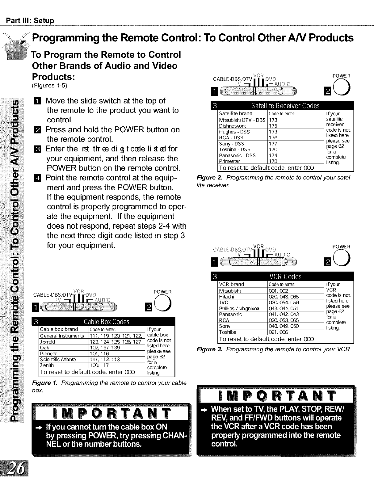
To Program the Remote to Control
Other Brands of Audio and Video
Products:
(Figures 1-5)
[] Move the slide switch at the top of
the remote to the product you want to
control.
[] Press and hold the POWER button on
the remote control.
[] Enter the rat tit ee di _ t cede li s_ed for
your equipment, and then release the
POWER button on the remote control.
[] Point the remote control at the equip-
ment and press the POWER button.
If the equipment responds, the remote
control is properly programmed to oper-
ate the equipment. If the equipment
does not respond, repeat steps 2-4 with
the next three digit code listed in step 3
for your equipment.
mini
v_[,qs[q_il
CABLE JDBSA]TVI_ )V[}
iV 1| | IrAU )0
POWER
E
Cable box brand
General Ina_-uments
Jerrold
Oak
Pioneer
Scientific A_ante
Zenith
Code to enter:
111,119, 120, 121,122,
123, 124, 125, 126, 127
102_ 137, 139
101,116
111, 11Z 113
lOG, 117
To reset to defaultcode, enter 000
If your
cable box
code is not
listed here,
please see
page 62
for a
complete
lis_ng,
Figure 1. Programming the remote to control your cable
box.
[]
POWER
!
Satellit_ brand
lvbtsubishi DTV - DB:
Dishne'o_ork
Hughes - DSS
RCA - DSS
Sony - DSS
Toshiba - DSS
Panasonic - DSS
Pdmest_r
Code to enter:
173
175
173
176
177
170
174
178
To reset to default code, enter 000
If your
satellite
receiver
code is not
listed here,
_lease see
page 62
for a
complete
lis_ng.
Figure 2. Programming the remote to control your satel-
lite receive_
[]
POWER
!
VCR brand
lvhtsubishi
Hitachi
JVC
Phillips/Magnivox
Panasonic
RCA
Sony
Toshiba
Codeto enter:
001,002
020, 043, 065
030, 054, 059
043, 044, 051
041, O42,O43
020, 053, 065
048, 049, 050
021,066
To reset to default code, enter 000
If your
VCR
code is not
listed here,
31ease see
page 62
for a
complete
listing.
Figure 3. Programming the remote to control your VCR.
Part II1: Setup
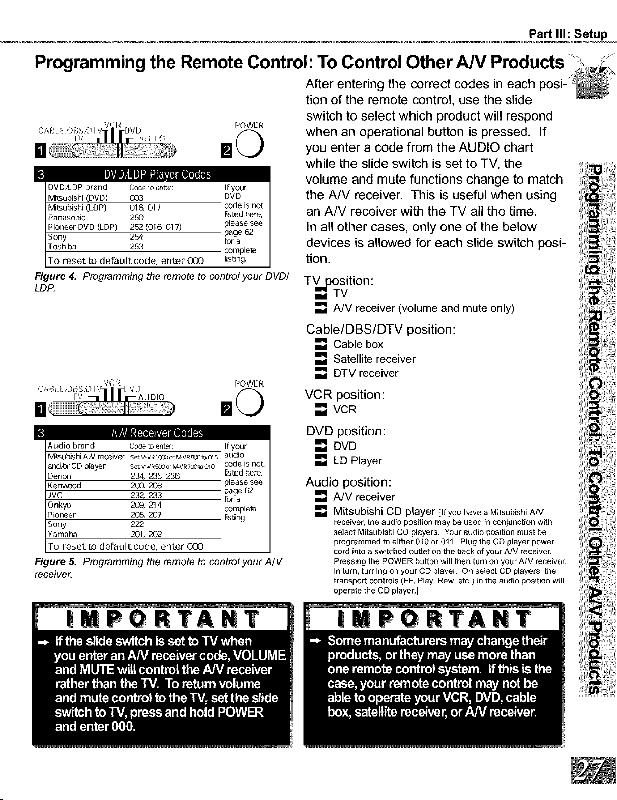
Programming the Remote Control: To Control Other AN
!
TV
POWER
DVD/LDP brand
M_tsubishi (DVD)
M_tsubishi (LDP)
Panasonic
Pioneer DVD (LDP)
Sony
Toshiba
Code to enter:
OO3
Ol& 017
25O
252 (016, 017)
254
253
To reset to default code, enter 000
If your
DVD
code is not
lised here,
31ease see
page 62
for a
complete
listfog,
Figure 4. Programming the remote to control your DVD/
LD!_
After entering the correct codes in each
tion of the remote control, use the slide
switch to select which product will respond
when an operational button is pressed. If
you enter a code from the AUDIO chart
while the slide switch is set to TV, the
volume and mute functions change to match
the A/V receiver. This is useful when using
an A/V receiver with the TV all the time.
In all other cases, only one of the below
devices is allowed for each slide switch posi-
tion.
TVjoosition:
_TV
[] A/V receiver (volume and mute only)
[]
TV
POWER
Cable/DBS/DTV position:
[] Cable box
[] Satellite receiver
[] DTV receiver
VCR position:
[] VCR
!
WA_
Audio brand
IVItsubishi AN receiver
and!or CD player
Denon
Kenwond
JVC
Onkyo
Pioneer
Sony
Yamaha
Code to enter:
SeLM-VR 1QOQor M-VRSOOto 015
Set M-V R££10or M-V R7QO_3010
234, 235, 236
2_, 208
232, 233
209, 214
205, 207
222
201,202
To reset to default code, enter 000
If your
audio
code is not
listed here,
31ease see
page 62
for a
complete
listfog,
Figure 5. Programming the remote to control your A/V
receive_
DVD position:
[] DVD
[] LD Player
Audio position:
[] A/V receiver
[] Mitsubishi CD player [If you have a Mitsubishi A/V
receiver, the audio position may be used in conjunction with
select Mitsubishi CD players. Your audio position must be
programmed to either 010 or 011. Plug the CD player power
cord into a switched outlet on the back of your A/V receiver.
Pressing the POWER button will then turn on your A/V receiver,
in turn, turning on your CD player. On select CD players, the
transport controls (FF, Play, Rew, etc.) in the audio position will
operate the CD player.]
Part II1: Setup
Programming the Remote Control:
To Activate the System 4 Home Theater IR Control
Activation of the System 4 Home
Theater IR Control
For select brands of digital A/V receiver's,
you can set up the remote control to auto-
matically select the correct audio input when
you press the HOME THEATER button. At
the same time, the TV will select the correct
5 video input. This allows you to watch your
best type of video (Component, S-Video)
with your best type of audio (Dolby Digital,
Pro Logic, etc.) conveniently. See System
4 Home Theater IR Control, page 22, for
connection instructions.
III
Once properly activated, when the HOME
THEATER button is pressed, System 4 Oper-
ates In 2 Parts:
Changes a compatible digital A/V
receiver to the correct input for the device
you wish to operate.
Changes the TV to the correct input
for the device you wish to operate.
Both functions can operate simultaneouslywithonetouche,theHOMETHEATER
button. However, you may activate only one
if you desire (video to control the TV or
audio to control the A/V Receiver). The
remote control must be programmed to the
appropriate A/V Receiver code prior to the
activation of the audio portion (see To Pro-
gram the Remote to Control Other Brands of
Audio and Video Products, page 26).
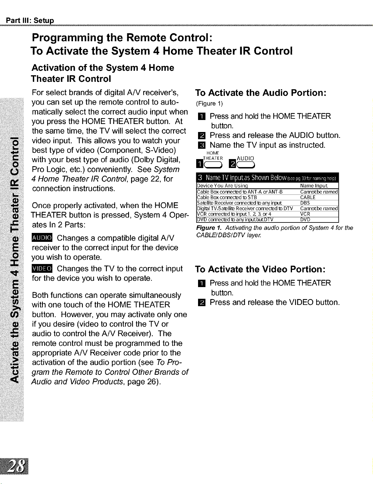
To Activate the Audio Portion:
(Figure 1)
[] Press and hold the HOME THEATER
button.
[] Press and release the AUDIO button.
[] Name the TV input as instructed.
HOME
_111" ll . IO Ill i# O A . • it
Device You Are Using Name Input
Cable Box connec_ _aANTRA or ANT-B Cannot be namec
Cable Box connec_ _aSTB CABLE
Sa_llie Receiver connected tD any input DBS
Diqi_l TV/Sal_Ili_ Receiver connec_d _ DTV Cannotbe namec
VCR connec_d "_ input 1, 2 3, or 4 VCR
DVD connec_d "_ any inp_but DTV DVD
Figure I. Activating the audio portion of System 4 for the
CABLE/DBS/DTV laye_
To Activate the Video Portion:
[] Press and hold the HOME THEATER
button.
[] Press and release the VIDEO button.
Part II1: Setup
Programming the Remote Control:
To Activate the System 4 Home Theater IR Control
Testing System 4 for Proper Setup
[]
[]
[]
Move the slide switch to the position you
wish to test.
Point the remote at the TV.
Press and release the HOME THEATER
button. If the audio portion has been
properly setup, your A/V receiver will
have changed to the appropriate input
as indicated in table 1, page 15. If the
video connection of your System 4 has
been properly setup, your TV will have
changed to the appropriate input.
If the TV did not change inputs...
[] Repeat To Activate the Video Portion, page 28,
and retest.
Deactivating the System 4 Home
Theater IR Control
[] Simultaneously press the CANCEL
button and the HOME THEATER button.
[] Repeat To Activate the Video Portion,
page 28.
If the A/V Receiver did not change
inputs...
[] Repeat Specia/Setups, page 15, and retest.
[] Reposition IR emitter(s) and retest
[] Repeat To Activate the Audio Portion, page 28,
and retest.
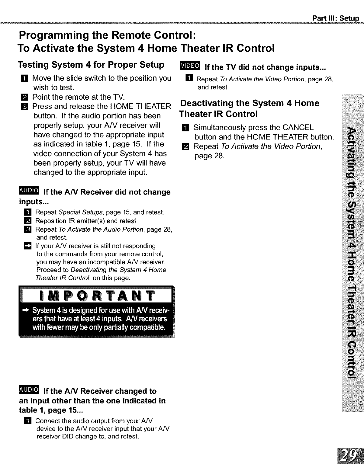
[] If your A/V receiver is still not responding
to the commands from your remote control,
you may have an incompatible A/V receiver.
Proceed to Deactivating the System 4 Home
Theater/R Contro/, on this page.
If the A/V Receiver changed to
an input other than the one indicated in
table 1, page 15...
[] Connect the audio output from your A/V
device to the A/V receiver input that your A/V
receiver DID change to, and retest.

Part II1: Setup
The 3D Graphical ! llJ l lll®Menu System
JrTV has Mitsubishi's exclusive 3D Graph-
ical I_L_IIII ° on-screen operating system,
which provides on-screen information for
menu choices and changes (Figure1).
A picture (icon) will be highlighted
when selected with the ADJUST
arrows. When selected, the appro-
priate menu will appear. You may
then make changes within the menu
or access sub-menus, if available.
A button indicates that you will access a
sub-menu or start an automatic function by
making this selection.
Figure 1. Main Menu: The Main Menu screen will always
be the r_ _crmn t hat _ppear sv_ en you pr ess t fe
MENU button.
The i_llr system includes the following
special features:
[] The currently selected icon or button is high-
lighted with a yellow outline and the text color
will be yellow.
[] On-screen instructions provide complete menu
choice information.
[] Some on-screen menu options must be set
before other options are available. For exam-
ple, "Set the Timer" will only be possible if
"Clock Time" and "Set Day" have been set.
The following buttons on your remote control
will help you to navigate within the I_IW_R ®
system (Figure 2):
[] ADJUST _ to select the menu item you want
to change.
[] ADJUST • or • to change the settings.
[] ENTER to enter into a menu, start an auto-
matic function, or select a checkbox.
[] CANCEL to clear a setting, or stop an auto-
matic function.
[] MENU to move back one menu screen at a
time.
[] HOME to exit all menus and return to TV
viewing.
vcR
CABLE _SX3TV DV[3
Tv-I I [w AUDIO
( II _ )
!
m
REC STOP PAUSE
R£W,££V PLAY FF/FWD
m_ MITSUBISHI
Figure 2. These buttons are used for navigation within
the I_ on-screen operating system.
Part II1: Setup
Menu Screens (Overview)
Figure 1. Setup menu
Figure 2. Captions menu
Figure 3. Channel menu
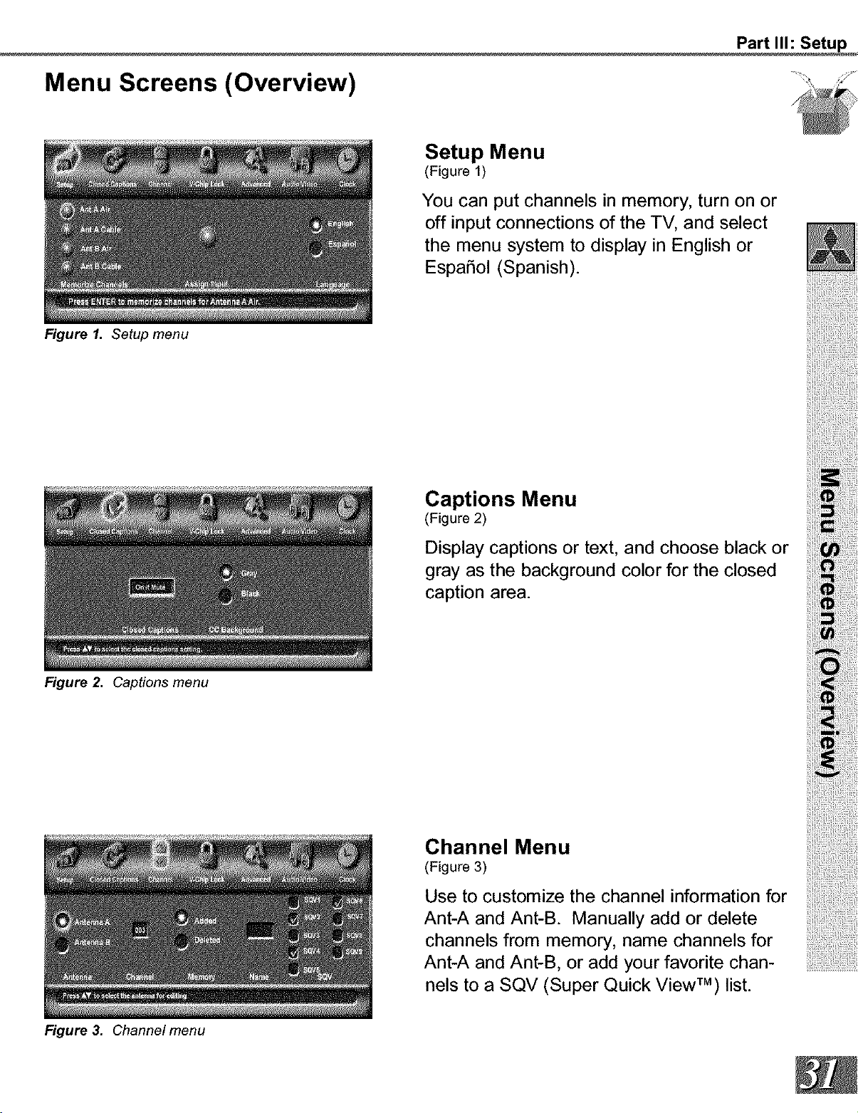
Setup Menu
(Figure 1)
You can put channels in memory, turn on or
off input connections of the TV, and select
the menu system to display in English or
EspaSol (Spanish).
Captions Menu
(Figure 2)
Display captions or text, and choose black or
gray as the background color for the closed
caption area.
Channel Menu
(Figure 3)
Use to customize the channel information for
Ant-A and Ant-B. Manually add or delete
channels from memory, name channels for
Ant-A and Ant-B, or add your favorite chan-
nels to a SQV (Super Quick View TM) list.
Part II1: Setup
Menu Screens (Overview)
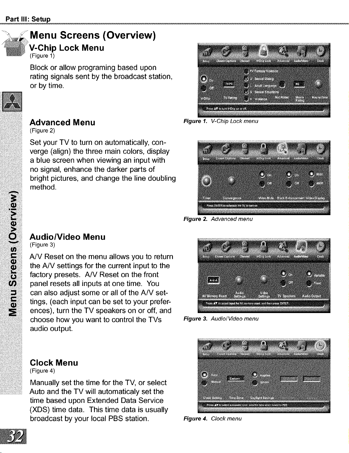
p Lock Menu
(Figure 1)
Block or allow programing based upon
rating signals sent by the broadcast station,
or by time.
Advanced Menu
(Figure 2)
Set your TV to turn on automatically, con-
verge (align) the three main colors, display
a blue screen when viewing an input with
no signal, enhance the darker parts of
bright pictures, and change the line doubling
method.
Audio/Video Menu
(Figure 3)
A/V Reset on the menu allows you to return
the A/V settings for the current input to the
factory presets. A/V Reset on the front
panel resets all inputs at one time. You
can also adjust some or all of the A/V set-
tings, (each input can be set to your prefer-
ences), turn the TV speakers on or off, and
choose how you want to control the TVs
audio output.
Clock Menu
(Figure 4)
Manually set the time for the TV, or select
...........................Auto and the TV will automaticaly set the
time based upon Extended Data Service
(XDS) time data. This time data is usually
broadcast by your local PBS station.
Figure 1. V-Chip Lock menu
Figure 2. Advanced menu
Figure 3. Audio/Video menu
Figure 4. Clock menu
Part II1: Setup
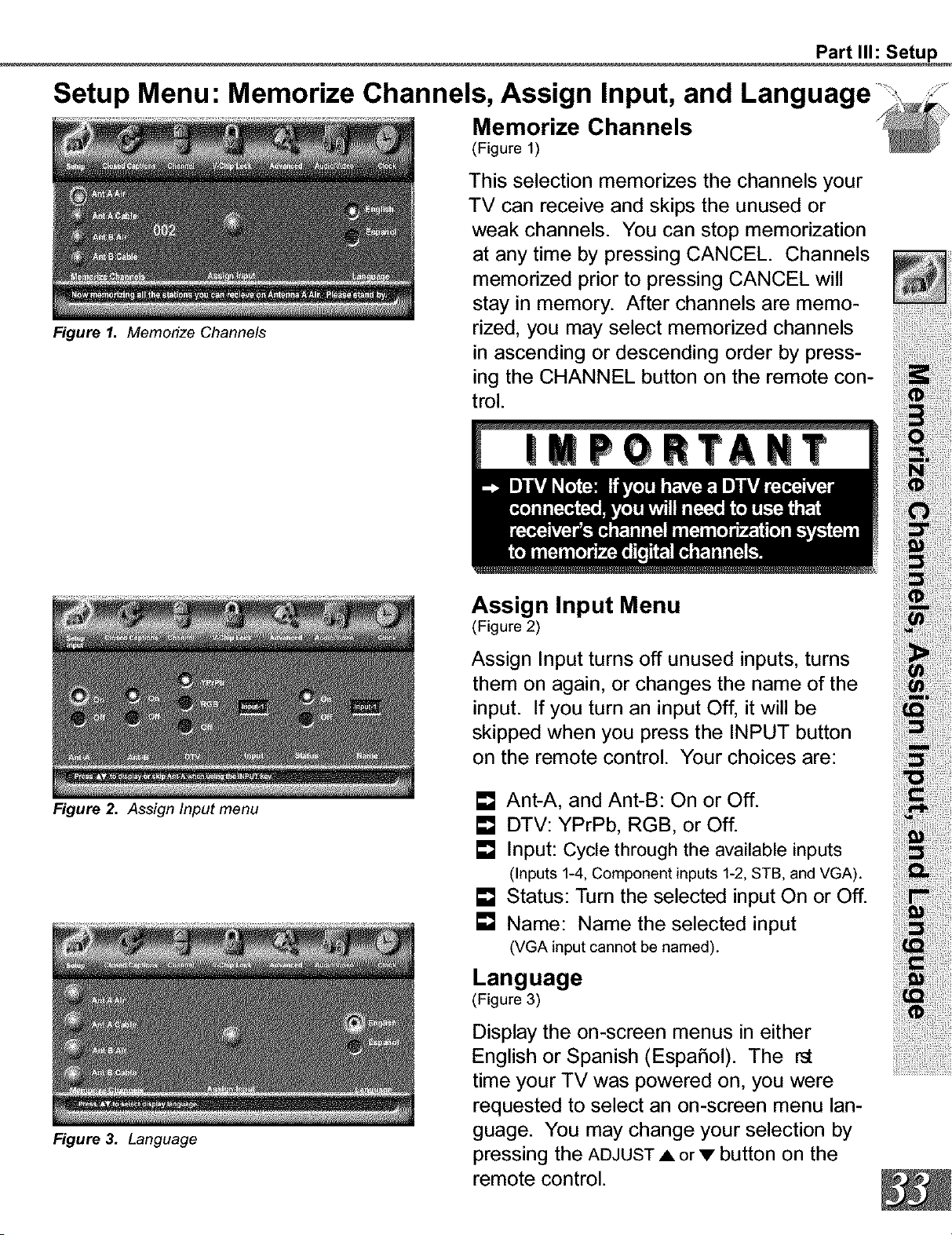
Setup Menu: Memorize Channels, Assign Input, and Language
Memorize Channels
(Figure 1)
Figure I. Memorize Channels
Figure 2. Assign Input menu
Figure 3. Language
This selection memorizes the channels your
TV can receive and skips the unused or
weak channels. You can stop memorization
at any time by pressing CANCEL. Channels
memorized prior to pressing CANCEL will
stay in memory. After channels are memo-
rized, you may select memorized channels
in ascending or descending order by press-
ing the CHANNEL button on the remote con-
trol.
Assign Input Menu
(Figure 2)
Assign Input turns off unused inputs, turns
them on again, or changes the name of the
input. If you turn an input Off, it will be
skipped when you press the INPUT button
on the remote control. Your choices are:
[] Ant-A, and Ant-B: On or Off.
[] DTV: YPrPb, RGB, or Off.
[] Input: Cycle through the available inputs
(Inputs 1-4, Component inputs 1-2, STB, and VGA).
[] Status: Turn the selected input On or Off.
[] Name: Name the selected input
(VGA input cannot be named).
Language
(Figure 3)
Display the on-screen menus in either
English or Spanish (EspaSol). The
time your TV was powered on, you were
requested to select an on-screen menu lan-
guage. You may change your selection by
pressing the ADJUST • or • button on the
remote control.
Part II1: Setup
Captions Menu: Closed Captions
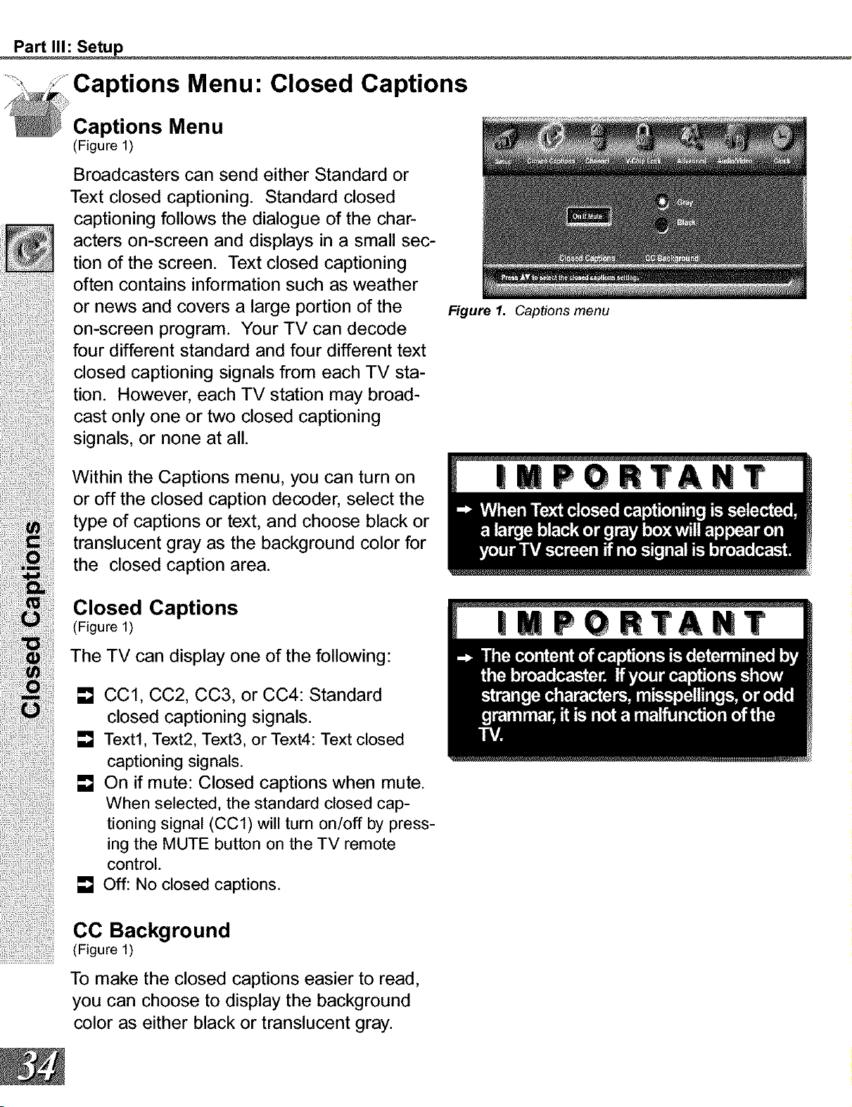
Captions Menu
(Figure 1)
Broadcasters can send either Standard or
Text closed captioning. Standard closed
captioning follows the dialogue of the char-
acters on-screen and displays in a small sec-
tion of the screen. Text closed captioning
often contains information such as weather
or news and covers a large portion of the
on-screen program. Your TV can decode
four different standard and four different text
closed captioning signals from each TV sta-
tion. However, each TV station may broad-
cast only one or two closed captioning
signals, or none at all.
Within the Captions menu, you can turn on
or off the closed caption decoder, select the
type of captions or text, and choose black or
translucent gray as the background color for
the closed caption area.
Closed Captions
(Figure I)
The TV can displayone ofthe following:
[] CC1, CC2, CC3, or CC4: Standard
closed captioning signals.
[] Text1, Text2, Text3, or Text4: Text closed
captioning signals.
[] On if mute: Closed captions when mute.
When selected, the standard closed cap-
tioning signal (CC1) will turn on/off by press-
ing the MUTE button on the TV remote
control.
[] Off: No closed captions.
CO Background
(Figure 1)
To make the closed captions easier to read,
you can choose to display the background
color as either black or translucent gray.
Figure 1. Captions menu

Part II1: Setup
Channel Menu: Antenna, Channel, Memory, Name, and SQV TM _
Figure 1. Channel menu
SQV (Super Quick View TM)
Using The Menu Screen
(Figure 1)
SQV (Super Quick View TM) allows you to put
together a list of your favorite channels from Ant-A
and Ant-B. You can store up to 6 channels in
each of the 9 different memory banks. Once you
have added a channel to the SQV memory, "SQV"
will appear under the channel number on the TV
screen.
Antenna
(Figure 1)
Select Ant-A, or Ant-B. For each antenna,
you can add or delete channels in memory,
name channels, and add channels to the
SQV (Super Quick View TM) list.
Channel
(Figure 1)
Select the channel you want to add or delete
from memory, name, or add to the SQV
Super Quick View TM list.
Memow
(Figure 1)
After all available channels have been mem-
orized with Memorize Channels, page 33,
weaker channels viewed with Ant-A or Ant-B
can be added and unwanted channels can
be deleted.
Use the CHANNEL button on the remote
control to view memorized channels.
Name
(Figure 1)
Channels shown on Ant-A or Ant-B can be
given names (up to four characters). After
you enter a name, it will appear on the TV
screen, next to the channel number.
SQV (Super Quick View TM)
Using The Remote Control
Viewing and changing SQV banks using the
remote control:
[] Press the SQV button.
[] To change memory banks, press a
number button within 5 seconds of
pressing the SQV button.
[] Press the SQV button repeatedly to
cycle through the channels available in
that bank.
Adding SQV channels using the remote con-
trol:
[] Use the CHANNEL or number buttons
to select the channel you want to add to
the current SQV memory bank.
[] Press and hold the SQV button for
about 3 seconds. When "SQV" and the
memory bank number appear under the
channel number, the channel has suc-
cessfully been added.
Removing SQV channels using the remote
control:
[] Press the SQV button repeatedly until
you see the desired channel.
[] While the channel number and SQV indi-
cator are still displayed on the screen,
press the CANCEL button. If the
CANCEL button is not pressed before
the SQV indicator disappears, the chan-
nel will not be removed.
[] When the SQV indicator disappears, the
channel has successfully been removed.
Part II1: Setup
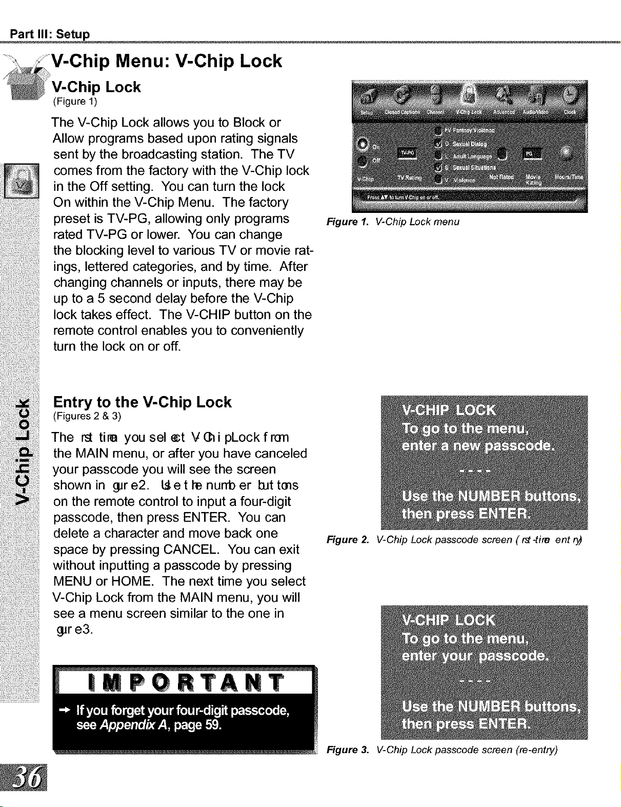
p Menu: V-Chip Lock
p Lock
(Figure 1)
The V-Chip Lock allows you to Block or
Allow programs based upon rating signals
sent by the broadcasting station. The TV
comes from the factory with the V-Chip lock
in the Off setting. You can turn the lock
On within the V-Chip Menu. The factory
preset is TV-PG, allowing only programs
rated TV-PG or lower. You can change
the blocking level to various TV or movie rat-
ings, lettered categories, and by time. After
changing channels or inputs, there may be
up to a 5 second delay before the V-Chip
lock takes effect. The V-CHIP button on the
remote control enables you to conveniently
turn the lock on or off.
Entry to the V-Chip Lock
(Figures 2 & 3)
The r_ tire you sel _t V(_i pLock fron
the MAIN menu, or after you have canceled
your passcode you will see the screen
shown in _r e2. L_e t he nurrb er bit tins
on the remote control to input a four-digit
passcode, then press ENTER. You can
delete a character and move back one
space by pressing CANCEL. You can exit
without inputting a passcode by pressing
MENU or HOME. The next time you select
V-Chip Lock from the MAIN menu, you will
see a menu screen similar to the one in
_r e3.
Figure 1. V-Chip Lock menu
Figure 2. V-Chip Lock passcode screen ( r_ -tire entry)
Figure 3. V-Chip Lock passcode screen (re-entry)
Part II1: Setup
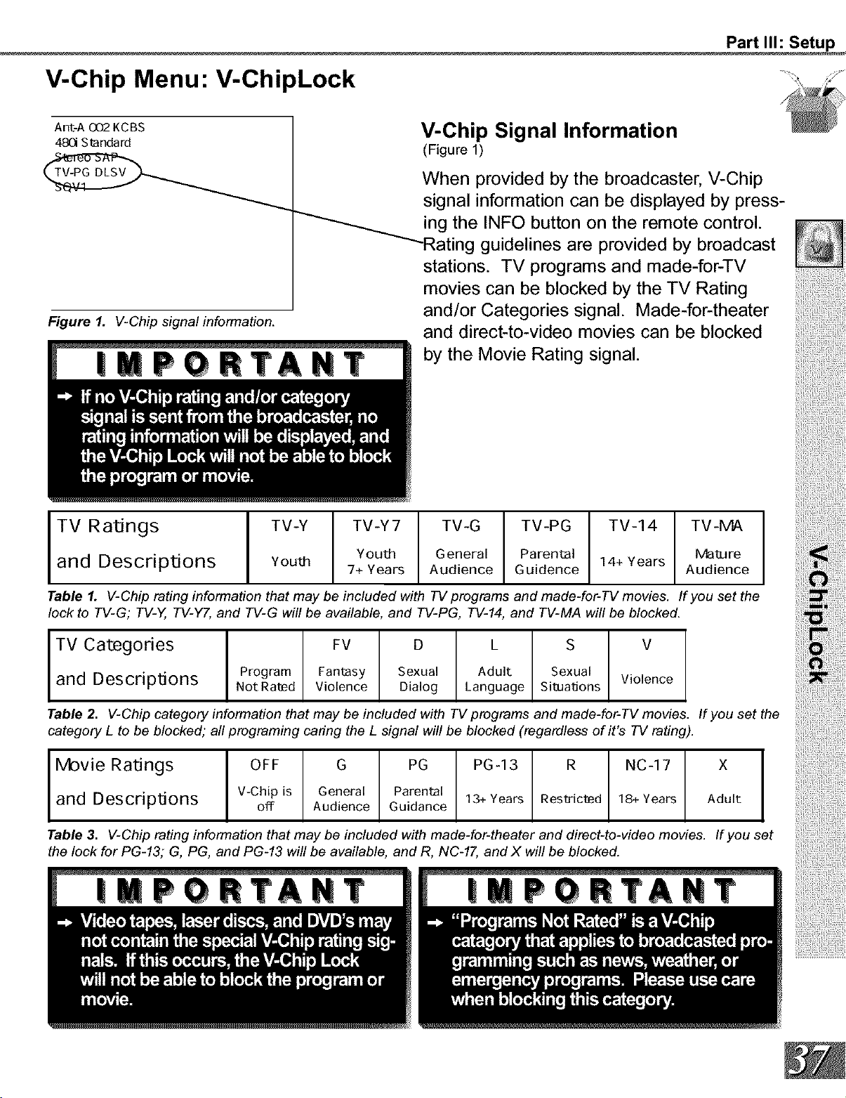
V-Chip Menu: V-ChipLock
Ant-A 002 KCBS
480 Standard
Figure 1. V-Chip signal information.
1
V-Chip Signal Information
(Figure 1)
When provided by the broadcaster, V-Chip
signal information can be displayed by press-
ing the INFO button on the remote control.
--Rating guidelines are provided by broadcast
stations. TV programs and made-for-TV
movies can be blocked by the TV Rating
and/or Categories signal. Made-for-theater
and direct-to-video movies can be blocked
by the Movie Rating signal.
I TV Ratings I TV-Y TV-Y7 TV-G TV-PG TV-14 TV-MA
I
You_ General Parental 14+ Years Ma_are
and Descriptions Youm 7+ Years Audience Guidence Audience
Table 1. V-Chip rating information that may be included with TV programs and made-for-TV movies. If you set the
lock to TV-G; TV-Y, TV-Y7, and TV-G will be available, and TV-PG, TV-14, and TV-MA will be blocked.
TV Categories I FV D L S V
and Descr ptions I Program Fantasy Sexual Adult Sexual Violence
Not Rated Violence Dialog Language Situations
Table 2. V-Chip category information that may be included with TV programs and made-for-TV movies. If you set the
category L to be blocked; all programing caring the L signal will be blocked (regardless of it's TV rating).
Movie Ratings I OFF G PG PG-13 R NC-17 X
and Descr ptions I V-Chipis General Parental
off Audience Guidance 13+ Years Res_ic_d 18+ Years Adult
Table 3. V-Chip rating information that may be included with made-for-theater and direct-to-video movies. If you set
the lock for PG-13; G, PG, and PG-13 will be available, and R, NC-17, and X will be blocked.
Part II1: Setup
p Menu: V-Chip Lock Hours/Time
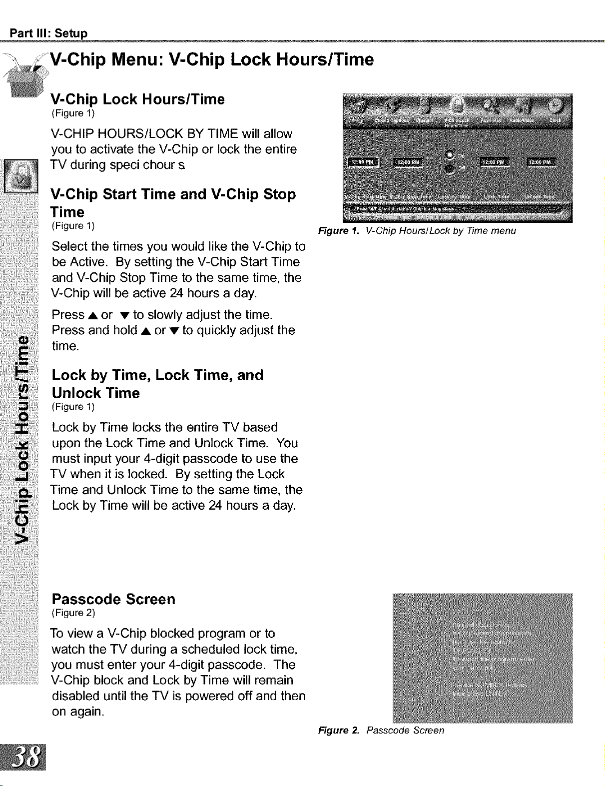
V-Chip Lock Hours/Time
(Figure 1)
V-CHIP HOURS/LOCK BY TIME will allow
you to activate the V-Chip or lock the entire
TV during speci chour s
V-Chip Start Time and V-Chip Stop
Time
(Figure 1)
Select the times you would like the V-Chip to
be Active. By setting the V-Chip Start Time
and V-Chip Stop Time to the same time, the
V-Chip will be active 24 hours a day.
Press • or • to slowly adjust the time.
Press and hold • or • to quickly adjust the
time.
Lock by Time, Lock Time, and
Unlock Time
(Figure 1)
Lock by Time locks the entire TV based
upon the Lock Time and Unlock Time. You
must input your 4-digit passcode to use the
TV when it is locked. By setting the Lock
Time and Unlock Time to the same time, the
Lock by Time will be active 24 hours a day.
Figure 1. V-Chip Hours/Lock by Time menu
Passcode Screen
(Figure 2)
To view a V-Chip blocked program or to
watch the TV during a scheduled lock time,
you must enter your 4-digit passcode. The
...........................V-Chip block and Lock by Time will remain
disabled until the TV is powered off and then
on again.
Figure 2. Passcode Screen
Part II1:Setup
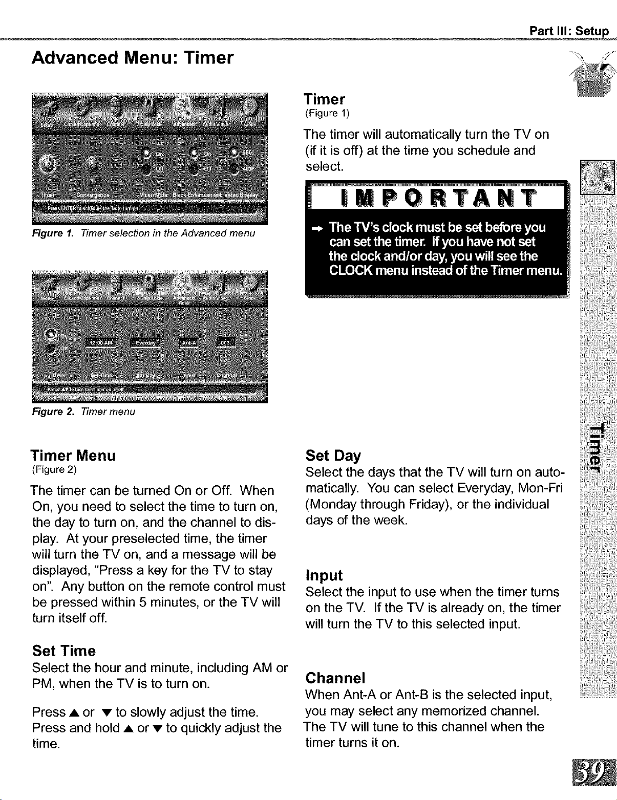
Advanced Menu: Timer
Figure I. Timer selection in the Advanced menu
Figure 2. Timer menu
Timer
(Figure 1)
The timer will automatically turn the TV on
(if it is off) at the time you schedule and
select.
Timer Menu
(Figure 2)
The timer can be turned On or Off. When
On, you need to select the time to turn on,
the day to turn on, and the channel to dis-
play. At your preselected time, the timer
will turn the TV on, and a message will be
displayed, "Press a key for the TV to stay
on". Any button on the remote control must
be pressed within 5 minutes, or the TV will
turn itself off.
Set Time
Select the hour and minute, including AM or
PM, when the TV is to turn on.
Press • or • to slowly adjust the time.
Press and hold • or • to quickly adjust the
time.
Set Day
Select the days that the TV will turn on auto-
matically. You can select Everyday, Mon-Fri
(Monday through Friday), or the individual
days of the week.
Input
Select the input to use when the timer turns
on the TV. If the TV is already on, the timer
will turn the TV to this selected input.
Channel
When Ant-A or Ant-B is the selected input,
you may select any memorized channel.
The TV will tune to this channel when the
timer turns it on.
Part II1: Setup
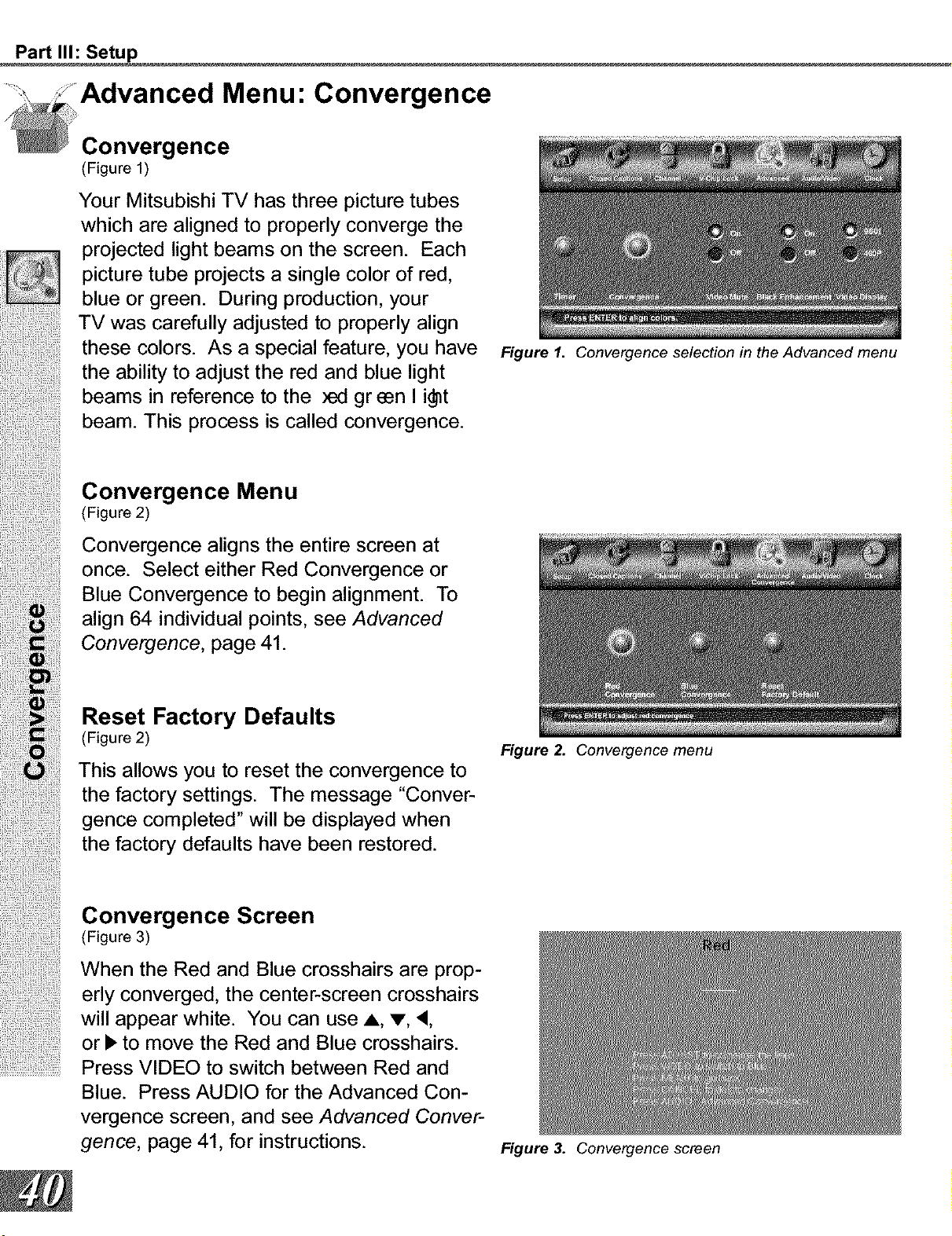
Menu: Convergence
Convergence
(Figure 1)
Your Mitsubishi TV has three picture tubes
which are aligned to properly converge the
projected light beams on the screen. Each
picture tube projects a single color of red,
blue or green. During production, your
TV was carefully adjusted to properly align
these colors. As a special feature, you have
the ability to adjust the red and blue light
beams in reference to the _ green I i_t
beam. This process is called convergence.
Convergence Menu
(Figure 2)
Convergence aligns the entire screen at
once. Select either Red Convergence or
Blue Convergence to begin alignment. To
align 64 individual points, see Advanced
Convergence, page 41.
Reset Factory Defaults
(Figure 2)
This allows you to reset the convergence to
the factory settings. The message "Conver-
gence completed" will be displayed when
the factory defaults have been restored.
Convergence Screen
(Figure 3)
When the Red and Blue crosshairs are prop-
erly converged, the center-screen crosshairs
will appear white. You can use A, v, <,
or I_ to move the Red and Blue crosshairs.
...........................Press VIDEO to switch between Red and
Blue. Press AUDIO for the Advanced Con-
vergence screen, and see Advanced Conver-
gence, page 41, for instructions.
Figure 1. Convergence selection in the Advanced menu
Figure 2. Convergence menu
Figure 3. Convergence screen
Part II1: Setup
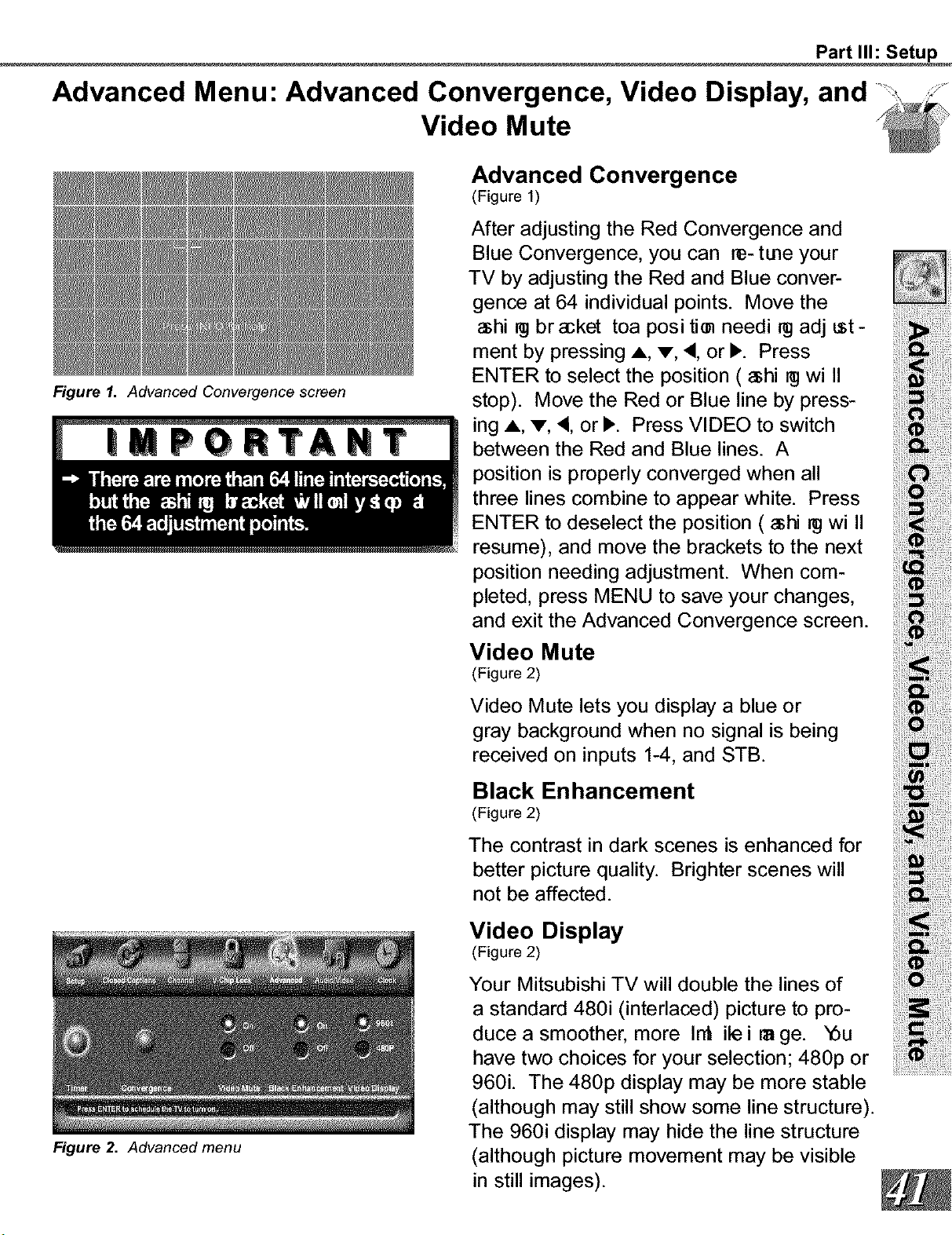
Advanced Menu: Advanced Convergence, Video Display, and
Video Mute
Figure I. Advanced Convergence screen
Figure 2. Advanced menu
Advanced Convergence
(Figure 1)
After adjusting the Red Convergence and
Blue Convergence, you can re- tune your
TV by adjusting the Red and Blue conver-
gence at 64 individual points. Move the
_shi _j bracket toa posi tim needi _ adj tst-
ment by pressing A, V, ', or )'. Press
ENTER to select the position ( _shi _j wi II
stop). Move the Red or Blue line by press-
ing A, V, <, or )'. Press VIDEO to switch
between the Red and Blue lines. A
position is properly converged when all
three lines combine to appear white. Press
ENTER to deselect the position ( _shi _ wi II
resume), and move the brackets to the next
position needing adjustment. When com-
pleted, press MENU to save your changes,
and exit the Advanced Convergence screen.
Video Mute
(Figure 2)
Video Mute lets you display a blue or
gray background when no signal is being
received on inputs 1-4, and STB.
Black Enhancement
(Figure 2)
The contrast in dark scenes is enhanced for
better picture quality. Brighter scenes will
not be affected.
Video Display
(Figure 2)
Your Mitsubishi TV will double the lines of
a standard 480i (interlaced) picture to pro-
duce a smoother, more In_ ile ira ge. _Su
have two choices for your selection; 480p or
960i. The 480p display may be more stable
(although may still show some line structure).
The 960i display may hide the line structure
(although picture movement may be visible
in still images).
Part II1: Setup
Menu: AV Memory Reset, and Audio/Video Settings
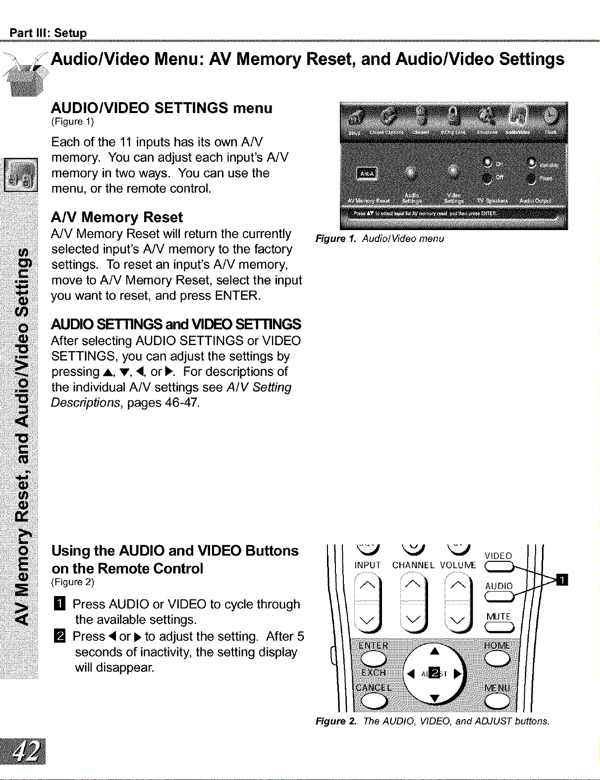
AUDIO/VIDEO SETTINGS menu
(Figure 1)
Each of the 11 inputs has its own A/V
memory. You can adjust each input's A/V
memory in two ways. You can use the
menu, or the remote control.
A/V Memory Reset
A/V Memory Reset will return the currently Figure1. Audio/Video menu
selected input's A/V memory to the factory
settings. To reset an input's A/V memory,
move to A/V Memory Reset, select the input
you want to reset, and press ENTER.
AUDIO SETTINGS and VIDEO SETTINGS
After selecting AUDIO SETTINGS or VIDEO
SETTINGS, you can adjust the settings by
pressing A, v, •, or b,. For descriptions of
the individual A/V settings see A/V Setting
Descriptions, pages 46-47.
Using the AUDIO and VIDEO Buttons _ _ _-J WDEO
on the Remote Control INPUTCHANNELVOLUIVE
[] Press AUDIO or VIDEO to cycle through
the available settings. MUTE
[] Press • or I_ to adjust the setting. After 5
seconds of inactivity, the setting display '
will disappear. ! A_I_,
Figure 2. The AUDIO, VIDEO, and ADJUST buttons.
Part II1: Setup
Audio/Video Menu: TV Speakers, and Audio Output
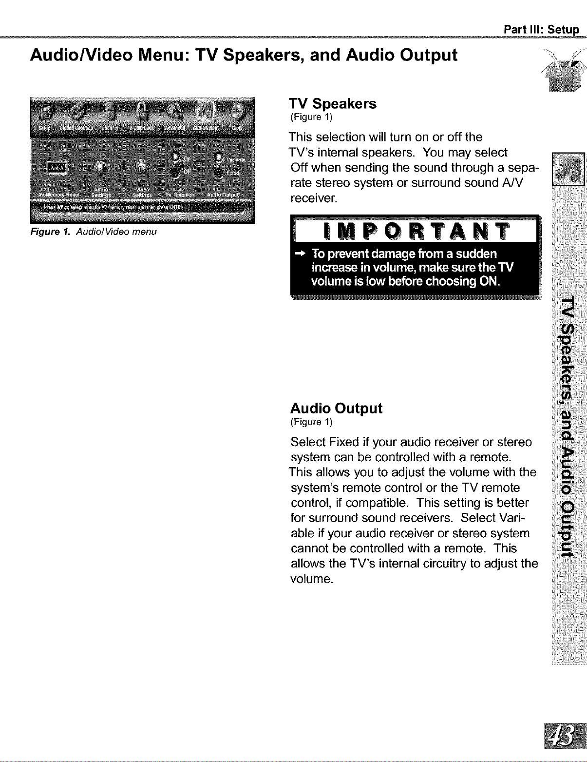
Figure 1. Audio/Video menu
TV Speakers
(Figure 1)
This selection will turn on or off the
TV's internal speakers. You may select
Off when sending the sound through a sepa-
rate stereo system or surround sound A/V
receiver.
Audio Output
(Figure 1)
Select Fixed if your audio receiver or stereo
system can be controlled with a remote.
This allows you to adjust the volume with the
system's remote control or the TV remote
control, if compatible. This setting is better
for surround sound receivers. Select Vari-
able if your audio receiver or stereo system
cannot be controlled with a remote. This
allows the TV's internal circuitry to adjust the
volume.
Part II1: Setup
Clock Menu: Clock Setting (Manual)
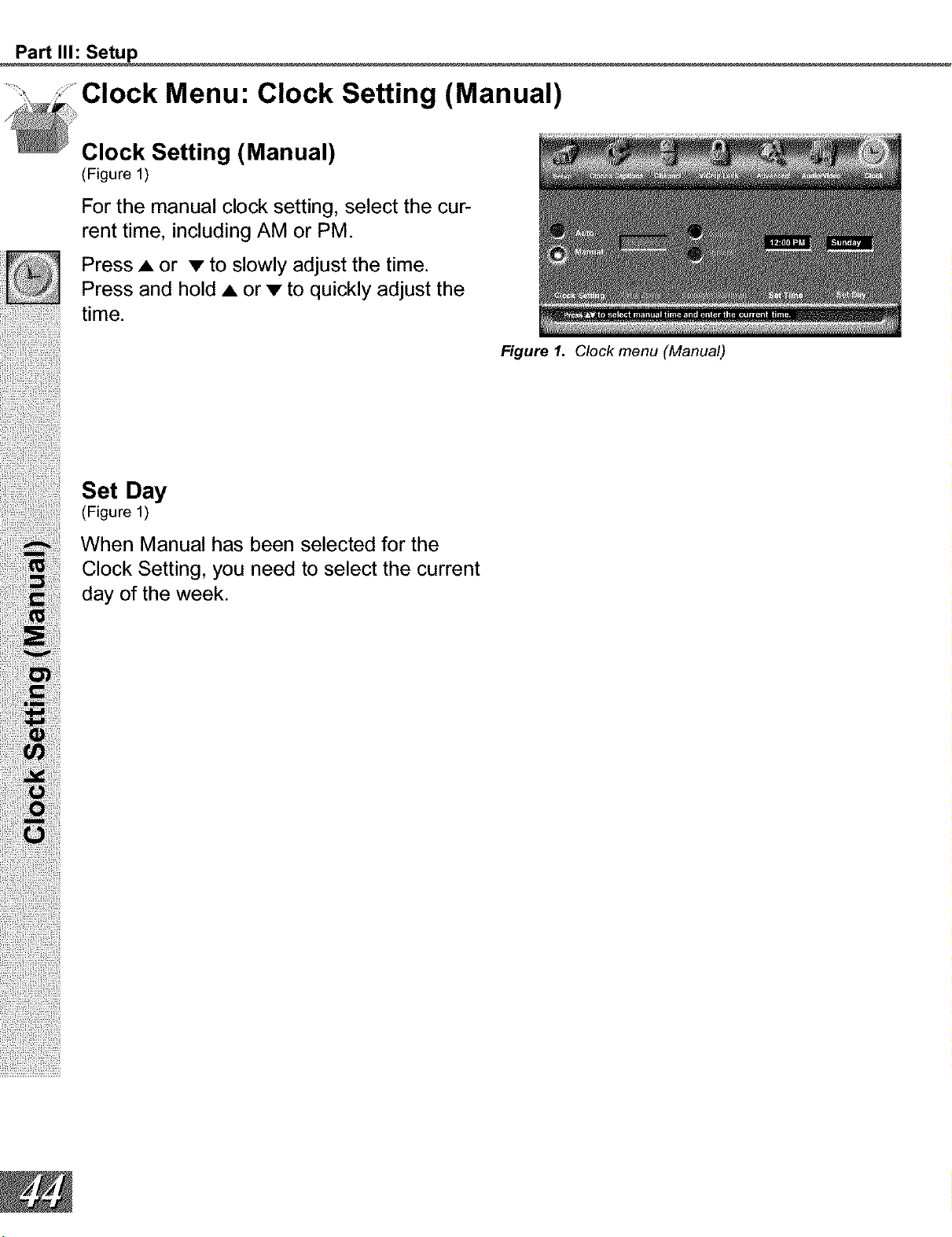
Clock Setting (Manual)
(Figure 1)
For the manual clock setting, select the cur-
rent time, including AM or PM.
Press • or • to slowly adjust the time.
Press and hold • or • to quickly adjust the
time.
Figure 1. Clock menu (Manual)
Set Day
(Figure 1)
When Manual has been selected for the
Clock Setting, you need to select the current
day of the week.
Part II1: Setup
Clock Menu: Clock Setting (Auto)
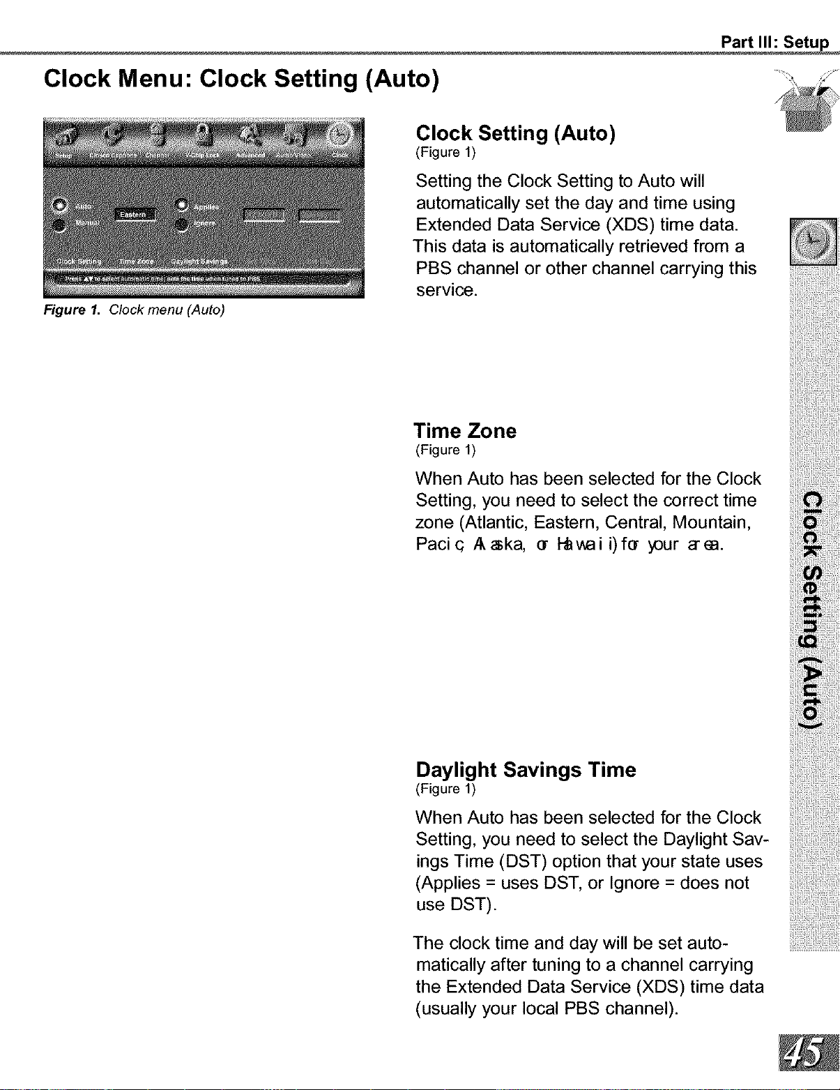
Figure 1. Clock menu (Auto)
Clock Setting (Auto)
(Figure 1)
Setting the Clock Setting to Auto will
automatically set the day and time using
Extended Data Service (XDS) time data.
This data is automatically retrieved from a
PBS channel or other channel carrying this
service.
Time Zone
(Figure 1)
When Auto has been selected for the Clock
Setting, you need to select the correct time
zone (Atlantic, Eastern, Central, Mountain,
Pacic Aska, er _v, ai i)fer y3ur a'm.
Daylight Savings Time
(Figure 1)
When Auto has been selected for the Clock
Setting, you need to select the Daylight Sav-
ings Time (DST) option that your state uses
(Applies = uses DST, or Ignore = does not
use DST).
The clock time and day will be set auto-
matically after tuning to a channel carrying
the Extended Data Service (XDS) time data
(usually your local PBS channel).
Part II1: Setup
Setting Descriptions: Audio
!!!!!!i!iiiii!_!!i_il| __!!_¸_¸¸i¸¸¸i¸_¸;i¸_¸¸_¸_!
Audio Settings
[] Bass enhances or reduces low fre-
quencysound.
[]
[]
[]
Treble enhances orreduces highfre-
quencysound.
Balance adjusts the level of sound
between the left and right speakers.
Surround creates simulated stereo and
surround effects. Your choices are:
• Off: No surround effects. Use this setting
when using an A/V receiver with Dolby TM Pro
Logic Surround, or Dolby TM Digital Surround.
• Simulated Stereo: Your TV will create a
simulated stereo effect when watching a non-
stereo program.
• Surround Sound: Your TV will create a
simulated surround effect when watching a
stereo program.
[] Listen to (for Ant-A and Ant-B) deter-
mines how your TV will receive a broad-
cast audio signal and play back the
sound you hear. Your choices are:
• Stereo: Default setting. The TV will play
stereo broadcasts in stereo and mono broad-
casts in mono. The word "Stereo" will be
displayed when you tune to a channel broad-
casting stereo.
• SAP (Second Audio Program): Additional
monaural soundtrack that you cannot hear
during normal TV viewing. The SAP signal
might be related to the program you are
watching, such as a soundtrack in a foreign
language, or unrelated to the program you
are watching, such as a weather report. If
a SAP signal is broadcast, the letters "SAP"
will be displayed when you tune to the chan-
nel.
• Mono: Reduces background noise, and
should be used when receiving a weak
stereo audio signal. All audio will be played
mono with this setting.
[] Listen to (for INPUTs) is not available.
[] Level Sound automatically equalizes
the volume level of programs containing
signi cant level differmces fro'non e
segment to another (for example, regu-
lar Programming to commercials). To
receive the best _1 itywi thmusi cpr(_
grams, you can turn this setting to Off.
Part II1: Setup
A/V Setting Descriptions: Video
Video Settings
[]
IRIS TM is the Intelligent Room Illumi-
nation (light) Sensor. When IRIS TM is
on, your TV will automatically adjust pic-
ture contrast and brightness for best
quality (Contrast and Brightness cannot
be adjusted manually).
[]
Contrast provides a slider to adjust
the white-to-black level. Low contrast
shows a variety of shades in darker
images, while high contrast shows
darker images more uniformly black and
makes colors appear more vibrant.
[] Brightness provides a slider to adjust
the overall brightness of the picture.
[] Sharpness provides a slider to adjust
the detail and clarity.
[] Color provides a slider to adjust the
color intensity.
[] Tint provides a slider to adjust the pro-
portion of red to green.
[] Color Temp (Color Temperature) allows
you to adjust how white images are dis-
played. Your choices are:
• Low 6500K or Low (for DTV): White images
will have a warm cast to them. This adjust-
ment is an average and can vary due to
ambient room lighting, video scene bright-
ness and the TV's age. The Low 6500K
represents the 6500K industry standard for
NTSC (non-DTV) pictures.
• Medium: White images will be balanced
between the Low (warm) and High (cool)
settings.
• High: White images will have a cool cast
to them. This setting may provide the most
realistic picture under bright lighting.
[] Video Noise reduces minor noise (grain-
iness) in the broadcast or input signal.
[] Image Type maximizes the original
camera media: Video or Film. Video
media uses a video camera and is cre-
ated at 30 frames per second. Film
media uses a Irrc arre r aand i scr eat ed
at 24 frames per second. Examples of
Video media are live TV broadcast such
as news, special events, or video taped
programs. Examples of Irane di aar e
motion pictures, made-for-TV movies,
and many prime time programs. Filmed
media is converted by the broadcaster
or home video company to 30 frames
per second to match TV or video stan-
dards. This conversion can leave subtle
"picture artifacts" or conversion errors.
Setting the Image Type to Film can
reduce the picture artifacts and improve
the picture quality, when viewing a 480i
image.
Part IV: Operation
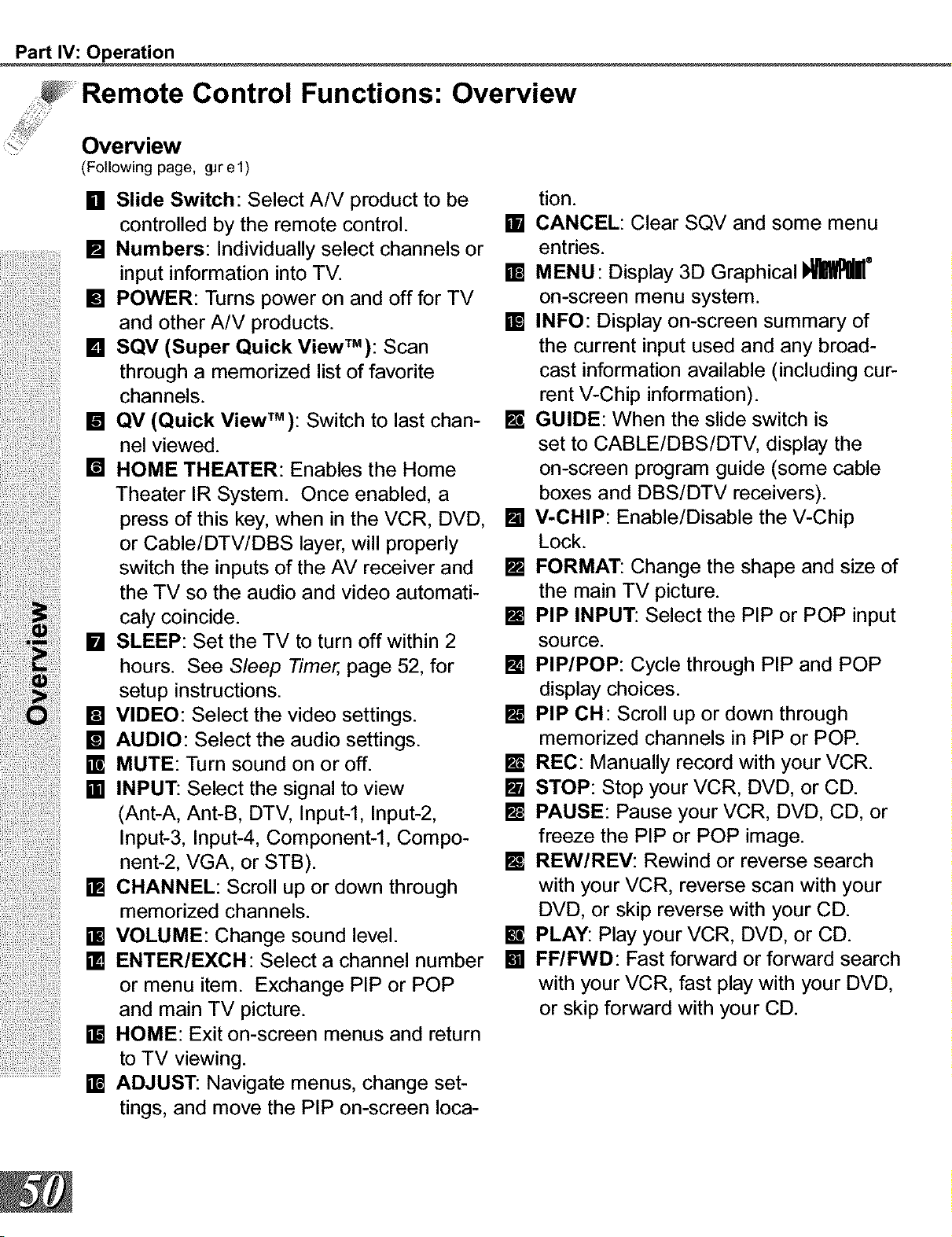
Control Functions: Overview
(Following page, _rel)
[] Slide Switch: Select A/V product to be
controlled by the remote control.
[] Numbers: Individually select channels or
input information into TV.
[] POWER: Turns power on and off for TV
and other A/V products.
[] SQV (Super Quick ViewT'): Scan
through a memorized list of favorite
channels.
[] QV (Quick View TM): Switch to last chan-
nel viewed.
[] HOME THEATER: Enables the Home
Theater IR System. Once enabled, a
press of this key, when in the VCR, DVD,
or Cable/DTV/DBS layer, will properly
switch the inputs of the AV receiver and
the TV so the audio and video automati-
caly coincide.
[] SLEEP: Set the TV to turn off within 2
hours. See S/eep Timer, page 52, for
setup instructions.
[] VIDEO: Select the video settings.
[] AUDIO: Select the audio settings.
E MUTE: Turn sound on or off.
[] INPUT: Select the signal to view
(Ant-A, Ant-B, DTV, Input-l, Input-2,
Input-3, Input-4, Component-I, Compo-
nent-2, VGA, or STB).
[] CHANNEL: Scroll up or down through
memorized channels.
[] VOLUME: Change sound level.
[] ENTER/EXCH: Select a channel number
or menu item. Exchange PIP or POP
and main TV picture.
[] HOME: Exit on-screen menus and return
to TV viewing.
ADJUST: Navigate menus, change set-
tings, and move the PIP on-screen Ioca-
........................... ]
tion.
[] CANCEL: Clear SQV and some menu
entries.
[] MENU: Display 3D Graphical !_E ®
on-screen menu system.
[] INFO: Display on-screen summary of
the current input used and any broad-
cast information available (including cur-
rent V-Chip information).
E GUIDE: When the slide switch is
set to CABLE/DBS/DTV, display the
on-screen program guide (some cable
boxes and DBS/DTV receivers).
[] V-CHIP: Enable/Disable the V-Chip
Lock.
[] FORMAT: Change the shape and size of
the main TV picture.
[] PIP INPUT: Select the PIP or POP input
source.
[] PIP/POP: Cycle through PIP and POP
display choices.
[] PIP CH: Scroll up or down through
memorized channels in PIP or POP.
E REC: Manually record with your VCR.
[] STOP: Stop your VCR, DVD, or CD.
[] PAUSE: Pause your VCR, DVD, CD, or
freeze the PIP or POP image.
[] REW/REV: Rewind or reverse search
with your VCR, reverse scan with your
DVD, or skip reverse with your CD.
Ira, PLAY: Play your VCR, DVD, or CD.
[] FF/FWD: Fast forward or forward search
with your VCR, fast play with your DVD,
or skip forward with your CD.
Part IV: Operation
Remote Control Functions: Care and Operation
W®W
REW_Y PLAY _F_WD
_ MIT_JBISI-II
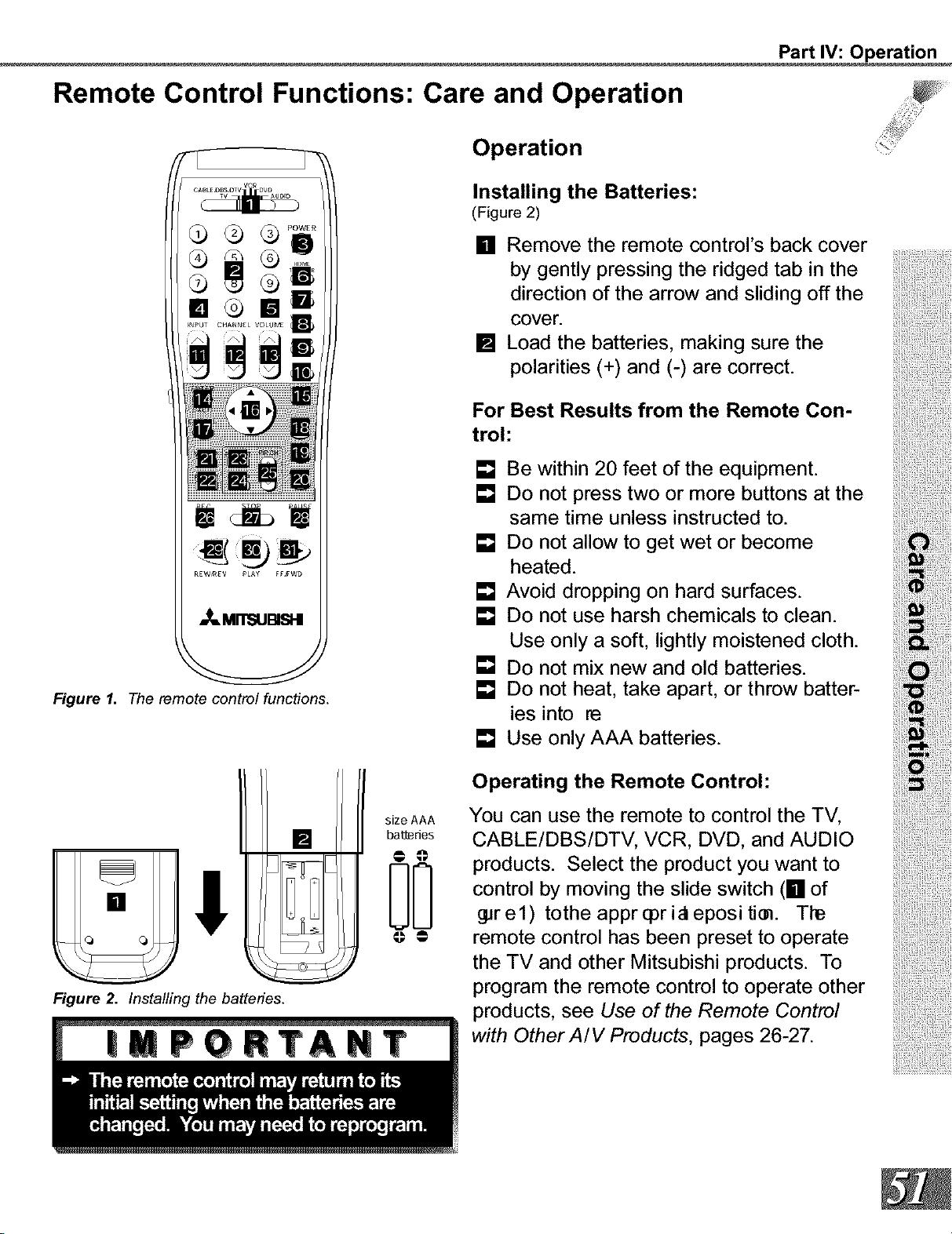
Figure 1. The remote control functions.
[]
Fq°r_
UoLJ
Figure 2. Installing the batteries.
size AAA
ba_des
ao
Operation
Installing the Batteries:
(Figure 2)
[] Remove the remote control's back cover
by gently pressing the ridged tab in the
direction of the arrow and sliding off the
cover.
[] Load the batteries, making sure the
polarities (+) and (-) are correct.
For Best Results from the Remote Con-
trol:
[] Be within 20 feet of the equipment.
[] Do not press two or more buttons at the
same time unless instructed to.
[] Do not allow to get wet or become
heated.
[] Avoid dropping on hard surfaces.
[] Do not use harsh chemicals to clean.
Use only a soft, lightly moistened cloth.
[] Do not mix new and old batteries.
[] Do not heat, take apart, or throw batter-
ies into re
[] Use only AAA batteries.
Operating the Remote Control:
You can use the remote to control the TV,
CABLE/DBS/DTV, VCR, DVD, and AUDIO
products. Select the product you want to
control by moving the slide switch (_ of
_rel) tothe apprqorialepositim. Tie
remote control has been preset to operate
the TV and other Mitsubishi products. To
program the remote control to operate other
products, see Use of the Remote Control
with Other A/V Products, pages 26-27.
Part IV: Operation
Remote Control Functions: Channel Selection and Sleep Timer
.... Channel Selection Sleep Timer
For Non-DTV Channels:
Setting the Sleep Timer:
[] Enter three numbers (for channel 2, [] Press SLEEP on the remote control.
press 002). [] A message indicating the length of time
or the sleep timer is to be set for is dis-
[] Press the channel number and ENTER played on the TV screen.
(for channel 2, press 2, then ENTER). [] Each press of SLEEP will increase
or the time displayed by 30 minutes, until
[] Enter the channel number and wait four the maximum value of 120 minutes is
seconds. The TV will change automati- reached.
cally. [] After 5 seconds of inactivity, the mes-
sage will disappear.
[] Press SLEEP to view the remaining time
before the timer turns the TV off.
Canceling the Sleep Timer:
[] Press SLEEP to display the on-screen
message.
[] Press SLEEP repeatedly until OFF is
displayed.
[] After 5 seconds of inactivity, the mes-
sage box will disappear.
Remote Control Functions: System 4 Home Theater IR Control
The Mitsubishi System 4 Home Theater IR to change inputs. You will automatically
hear the high quality digital surround sound
Control is a special feature that makes it
easier to use your TV with a digital surround from digital products like your DTV receiver
sound A/V receiver. Once your equipment and DVD player, and high quality analog
is properly connected and set up, your TV stereo or surround sound from non-digital
and digital A/V receiver will change inputs products like your VCR.
together, to match high resolution pictures
with the proper surround sound. Additionally, all IR remote signals from your
Mitsubishi remote or other manufacturers
When you change inputs on your TV to remote will be passed through your TV to
...........................watch different video products, your TV will your A/V devices. Your A/V devices can
send signals via your remote control and the be hidden or behind cabinet doors and con-
infrared emitters to your digital A/V receiver trolled by pointing the remote at the TV.
Part IV: Operation
Remote Control Functions: System 4 Home Theater IR Control
Requirements for Operation
[] A/V devices connected as described on page 15.
[] Cable Box connected as on page 16 or Cable Box with an S-Video output conneced as
on page 19, Connecting an S-Video Device.
[] TV connected to A/V receiver (TV Monitor Audio Out To A/V Receiver TV Input).
[] TV Inputs renamed (see page 33 for naming help):
Cable Box connected to Ant A or B =
Cable Box connected to STB =
VCR conneceted to Inputs 1-4 =
DVD conncected to any Input =
Satellite Receiver connected to any Input =
Digital Television Receiver on HD Input =
Cannot be Renamed
Rename To Cable
Rename To VCR
Rename To DVD
Rename To DBS
Cannot Be Renamed
[] Remote Control programmed to operate your other A/V Devices by System 4 properly
activated (see pages 28-29).
[] IR emiters properly connected and placed (see page 22).
Operation (VCR as example)
To watch your VCR:
[] Turn on the TV and A/V Receiver.
[] Move slide switch to VCR.
[] Point remote at the TV and press the HOME THEATER button.
[] The TV and A/V Receiver should change to the appropriate inputs.
[] Operate the VCR.
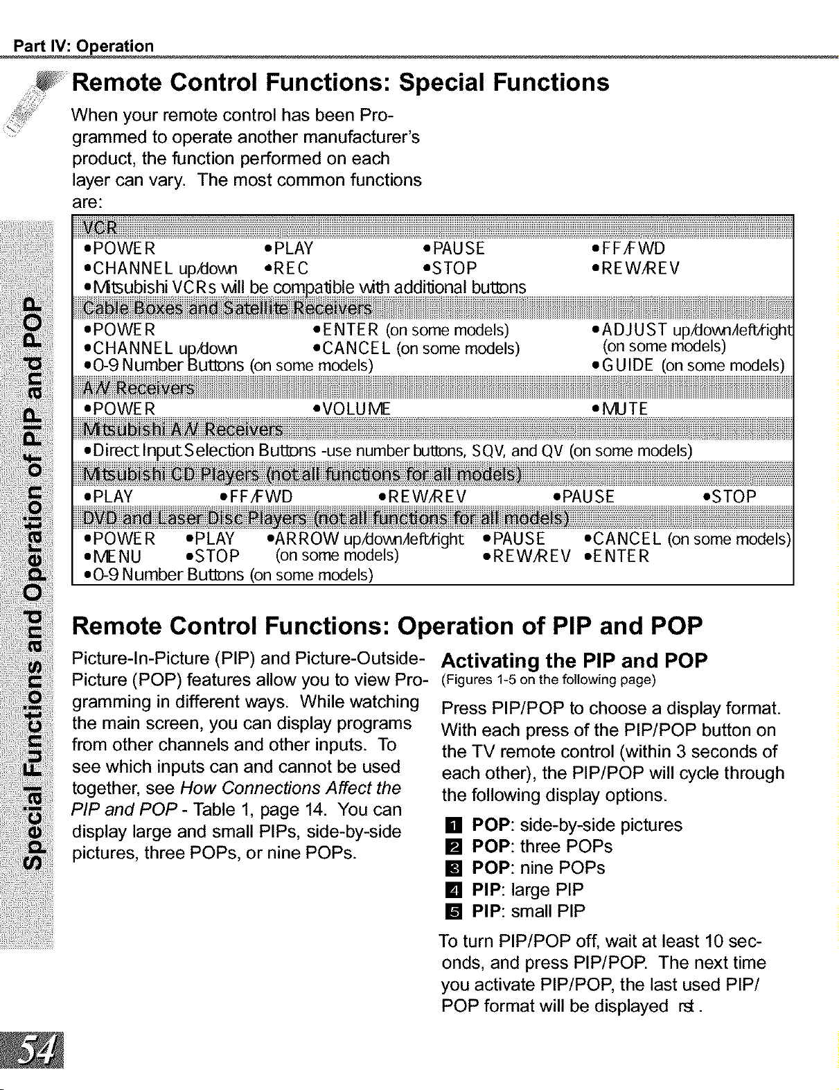
Part IV: Operation
Remote Control Functions: Special Functions
When your remote control has been Pro-
grammed to operate another manufacturer s
product, the function performed on each
layer can vary. The most common functions
are:
•M1subishi
• POWER • EN T E R (on some models)
*CHANNEL up/dovm •CANCEL (on some models)
• 0-9 N umber Buti_ns (on some models)
• A DJ US T up/dovm/lefftighl
(on some models)
*GUIDE (onsome models)
• POWER •VOLUME •MUTE
Buti_ns -use number buttDns, SQV, and QV (on some models)
• POWE R •PLAY •ARROW up/dovmAefftight
,ME NU *STOP (on some models)
• 0-9 Number But_ns (on some models)
•PAUSE
•REWAREV
• CANCEL (on
•ENTER
Remote Control Functions: Operation of PIP and POP
Picture-In-Picture (PIP) and Picture-Outside-
Picture (POP) features allow you to view Pro-
gramming in different ways. While watching
the main screen, you can display programs
from other channels and other inputs. To
see which inputs can and cannot be used
together, see How Connections Affect the
PIP and POP - Table 1, page 14. You can
display large and small PIPs, side-by-side
pictures, three POPs, or nine POPs.
Activating the PIP and POP
(Figures 1-5 on the following page)
Press PIP/POP to choose a display format.
With each press of the PIP/POP button on
the TV remote control (within 3 seconds of
each other), the PIP/POP will cycle through
the following display options.
[] POP: side-by-side pictures
[] POP: three POPs
[] POP: nine POPs
[] PIP: large PIP
[] PIP: small PIP
To turn PIP/POP off, wait at least 10 sec-
onds, and press PIP/POP. The next time
you activate PIP/POP, the last used PIP/
POP format will be displayed rst.
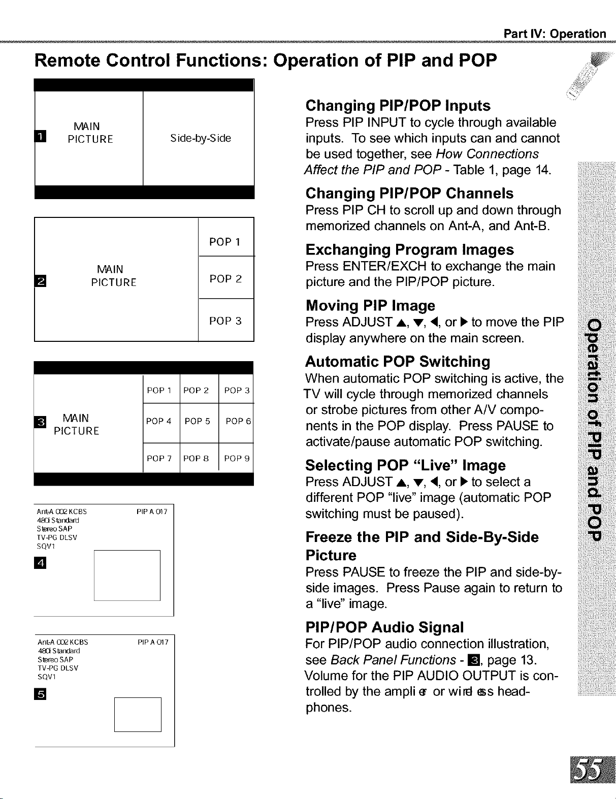
Part IV: Operation
Remote Control Functions: Operation of PIP and POP
MAIN
[] PICTURE
Side-by-S ide
[]
MAIN
PICTURE
POP 1
POP 2
POP 3
POP 1 POP 2 POP 3
[] MAIN
PICTURE
POP 4 POP 5 POP 6
POP 7 POP 8 POP 9
Ant=A QQ_ KCBS PiP A O17
48Ci Standard
Stereo SAP
TV=PG DLSV
SOV1
[]
Ant-A 002 KCBS PIP A O17
48Ci Standard
Stereo SAP
TV-PG DLSV
SQVl
[]
Changing PIP/POP Inputs
Press PIP INPUT to cycle through available
inputs. To see which inputs can and cannot
be used together, see How Connections
Affect the PIP and POP - Table 1, page 14.
Changing PIP/POP Channels
Press PIP CH to scroll up and down through
memorized channels on Ant-A, and Ant-&
Exchanging Program Images
Press ENTER/EXCH to exchange the main
picture and the PIP/POP picture.
Moving PIP Image
Press ADJUST A, v, 4, or b to move the PIP
display anywhere on the main screen.
Automatic POP Switching
When automatic POP switching is active, the
TV will cycle through memorized channels
or strobe pictures from other A/V compo-
nents in the POP display. Press PAUSE to
activate/pause automatic POP switching.
Selecting POP "Live" Image
Press ADJUST A, v, 4, or I_to select a
different POP "live" image (automatic POP
switching must be paused).
Freeze the PIP and Side-By-Side
Picture
Press PAUSE to freeze the PIP and side-by-
side images. Press Pause again to return to
a "live" image.
PIP/POP Audio Signal
For PIP/POP audio connection illustration,
see Back Panel Functions - 181,page 13.
Volume for the PIP AUDIO OUTPUT is con-
trolled by the ampli • or wi El _s head-
phones.
Part IV: Operation
Display Formats
Remote Control Functmns:
This is a wide screen TV (also known as [] Standard: This is the full screen format.
a 18:9 TV). This shape re _t st he new HDTV signals will automatically use this
types of images available from HDTV and
many DVDs. There are still many older style
narrow screen images (called 4:3 aspect
ratio) you will encounter. While there will
never be a perfect solution for displaying
a narrow image on a wide screen, Mitsubi-
shi offers several display formats to choose
from.
Press FORMAT on the TV remote control
to cycle through the _eavai Id01edi _ol aj
formats.
[]
format. This format is also useful to dis-
play Anamorphic DVDs that have 1.78:1
or 1.85:1 aspect ratios. Anamorphic
DVDs that have the 2.35:1 aspect ratio
will still display black bars at the top and
bottom. Narrow (4:3) images will be
stretched evenly from side to side.
Expand: This will enlarge the picture,
cropping off some of the image at the
top and bottom. This is useful to reduce
the letterbox top and bottom bars of non-
anamorphic DVDs or to correct narrow
(4:3) images that have been stretched in
the Standard format.
[] Zoom: This will enlarge the picture, crop-
ping off some of the image at each
side, and top and bottom. This is useful
to remove or reduce the black top and
bottom bars on anamorphic DVDs with
a 2.35:1 aspect ratio.
[]
Stretched: (Not available when viewing
480p signals) This format will stretch a
narrow (4:3) image across the screen,
however, there is less stretch in the
center than the sides. This will allow
the entire narrow image to be displayed
across the screen with less distortion
than seen in the Standard format.
[] Narrow: This format will display narrow
(4:3) images in their original shape, and
add stationary gray side bars to II tte
screen.
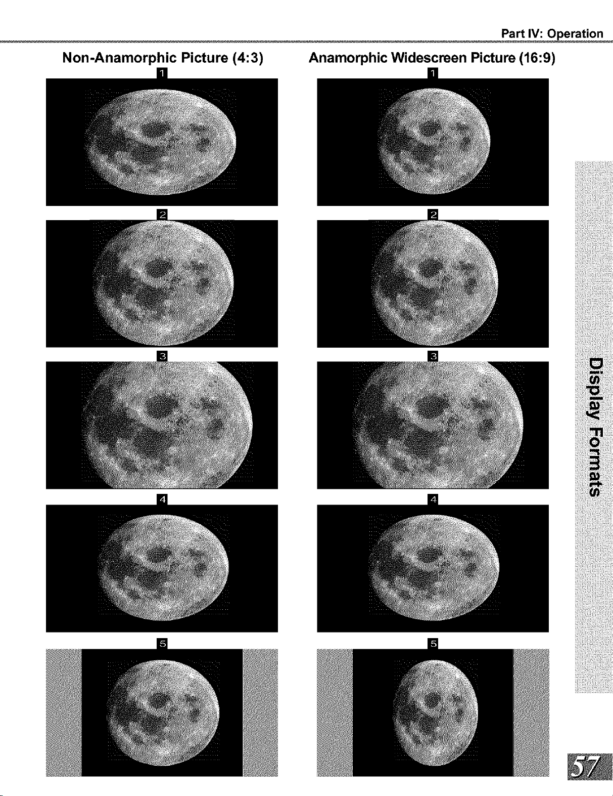
Part IV: Operation
Non-Anamorphic Picture (4:3) Anamorphic Widescreen Picture (16:9)
Part IV: Operation
Warning: Do not leave stationary or letterbox images on-screen for
extended periods of time. Mix the types of pictures shown.
Uneven picture tube aging is NOT covered by your warranty.
The normal use of a TV should include
a mixture of TV picture types. The most
frequently used picture types should II
the screen with constantly moving images
rather than stationary images or patterns.
Displaying the same stationary patterns
over extended periods of time, or display-
ing the same stationary pattern frequently
can leave a subtle but permanent ghost
image. To avoid this, mix your viewing
pattern. Do not show the same stationary
image for more than 15% of your total TV
viewing in any one week. Display con-
stantly moving and changing images that
II tfe screen whenever possi be
This projection TV uses picture tubes to
project the image to the screen. All
picture tubes age with use. As they
age, their light output is gradually reduced.
Normal TV pictures II tfe screen _i th
constantly changing images. Under these
conditions, picture tubes age at an even
rate across the entire screen. This main-
tains a TV picture that is evenly bright over
the whole screen. Stationary images or
images that only partially II tfe screen
(leaving black or colored bars to II tfe
screen), when used over extended periods
of time or when viewed repeatedly, can
cause uneven aging of the phosphors
and leave subtle ghosts of the stationary
images in the picture.
Still or stationary images may be received
from broadcasters, cable channels, sat-
ellite channels, DVD discs, video tapes,
laser discs, on-line services, web/internet
searching devices, video games, and digi-
tal TV tuner/converter boxes. Examples of
these types of images can be, but are not
limited to the following:
[] Letterbox top/bottom black bars:
shown at the top and bottom of the TV
screen when you watch a widescreen
(16:9) movie on a standard (4:3) TV.
[] Side bar images: solid bars shown
on each side of an image when watch-
ing a standard (4:3) program on a wi-
descreen (16:9) TV.
[] Stock-market report bars: ticker run-
ning at the bottom of the TV screen.
[] Shopping channel loges & pricing dis.
plays: bright graphics that are shown con-
stantly or repeatedly in the same location.
[] Video game patterns and scoreboards
[] Bright station loges: moving or low-
contrast graphics are less likely to cause
uneven aging of the picture tubes.
[] On-line (internet) web sites: or any
other stationary or repetitive computer style
images.
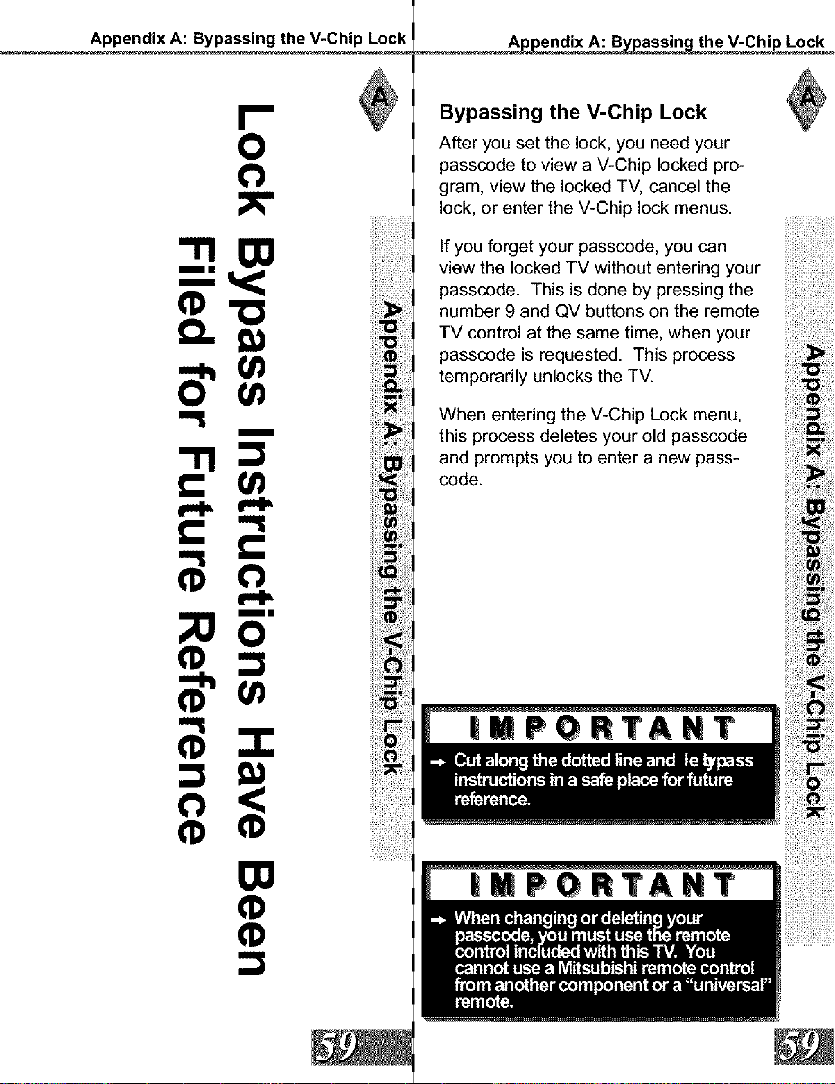
Appendix A: Bypassing the V-Chip Lock
0
"1100
mm
U)
0 u_
====mm
mm
;Oo
o <
¢ ¢
O0
Bypassing the V-Chip Lock
After you set the lock, you need your
passcode to view a V-Chip locked pro-
gram, view the locked TV, cancel the
lock, or enter the V-Chip lock menus.
If you forget your passcode, you can
view the locked TV without entering your
passcode. This is done by pressing the
number 9 and QV buttons on the remote
TV control at the same time, when your
passcode is requested. This process
temporarily unlocks the TV.
When entering the V-Chip Lock menu,
this process deletes your old passcode
and prompts you to enter a new pass-
code.
| T T
| T T

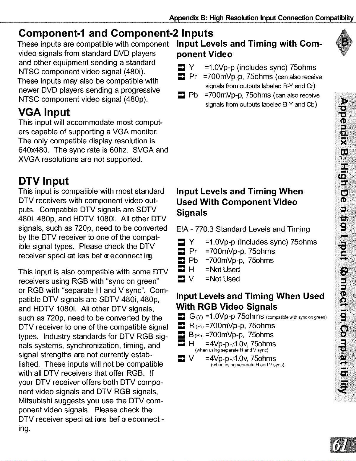
Appendix B: Hi h Resolution Input Connection Compatibl"
Component-1 and Component-2 Inputs
These inputs are compatible with component
video signals from standard DVD players
and other equipment sending a standard
NTSC component video signal (480i). [] Y
[] Pr
These inputs may also be compatible with
newer DVD players sending a progressive
NTSC component video signal (480p). [] Pb
VGA Input
This input will accommodate most comput-
ers capable of supporting a VGA monitor.
The only compatible display resolution is
640x480. The sync rate is 60hz. SVGA and
XVGA resolutions are not supported.
Input Levels and Timing with Com-
ponent Video
=l.0Vp-p (includes sync) 75ohms
=700mVp-p, 75ohms (can also receive
signals from outputs labeled R-Y and Cr)
=700mVp-p, 75ohms (can alsoreceive
signals from outputs labeled B-Y and Cb)
DTV Input
This input is compatible with most standard
DTV receivers with component video out-
puts. Compatible DTV signals are SDTV
480i, 480p, and HDTV 1080i. All other DTV
signals, such as 720p, need to be converted
by the DTV receiver to one of the compat-
ible signal types. Please check the DTV
receiver speci cat ires bef • econnect i_.
This input is also compatible with some DTV
receivers using RGB with "sync on green"
or RGB with "separate H and V sync". Com-
patible DTV signals are SDTV 480i, 480p,
and HDTV 1080i. All other DTV signals,
such as 720p, need to be converted by the
DTV receiver to one of the compatible signal
types. Industry standards for DTV RGB sig-
nals systems, synchronization, timing, and
signal strengths are not currently estab-
lished. These inputs will not be compatible
with all DTV receivers that offer RGB. If
your DTV receiver offers both DTV compo-
nent video signals and DTV RGB signals,
Mitsubishi suggests you use the DTV com-
ponent video signals. Please check the
DTV receiver speci cat ires bef e econnect -
ing.
Input Levels and Timing When
Used With Component Video
Signals
EIA - 770.3 Standard Levels and Timing
[]Y
[] Pr
[] Pb
[]H
=l.0Vp-p (includes sync) 75ohms
=700mVp-p, 75ohms
=700mVp-p, 75ohms
= Not Used
[] V =Not Used
Input Levels and Timing When Used
With RGB Video Signals
[] G (¥) =l.0Vp-p 75ohms (compatiblewithsyncongreen)
[] R(p0 =700mVp-p, 75ohms
[] B(Pb)=700mVp-p, 75ohms
[] H =4Vp-p+/-l.0v, 75ohms
(when using separate H and V sync)
[] V =4Vp-p+/-l.0v, 75ohms
(when using separate H and V sync)
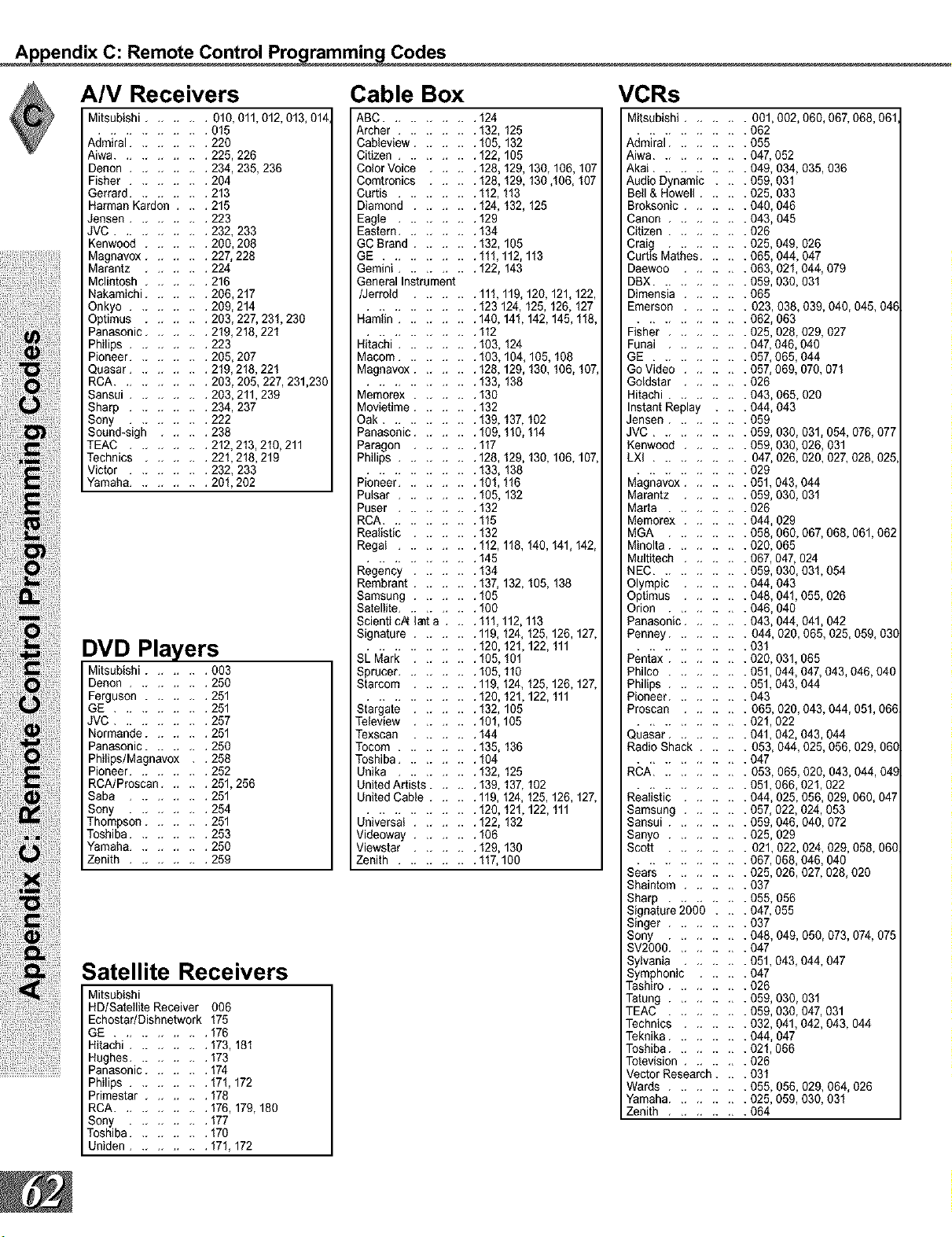
Appendix C: Remote Control Pro rammin Codes
,_ iii,!i!ii iiiiii i!i
A/V Receivers
Mitsubishi ........ 010,011,012,013,014,
.............. 015
Admiral .......... 220
Aiwa ............ 225,226
Denon .......... 234,235,236
Fisher .......... 264
Gerrard .......... 213
Harman Kardon .... 215
Jansen .......... 223
JVC ............ 232,233
Kenwood ........ 200,208
Magnavox ........ 227,228
Marantz ........ 224
Mclintosh ........ 216
Nakamichi ........ 206,217
Onkyo .......... 209,214
Optimus ........ 203, 227, 231,230
Panasonic ........ 219, 218, 221
Philips .......... 223
Pioneer .......... 205,207
Quasar .......... 219,218,221
RCA ............ 203,205,227,231,230
Sansai .......... 203,211,239
Sharp .......... 234, 237
Sony .......... 222
Sound-sigh ...... 238
TEAC .......... 212,213,210,211
Technics ........ 221,218,219
Victor .......... 232, 233
Yamaha .......... 201,202
DVD Players
Mitsubishi ........ 003
Denon .......... 250
Ferguson ........ 251
GE ............ 251
JVC ............ 257
Normande ........ 251
Panasonic ........ 250
Philips/Magnavox . . 258
Pioneer .......... 252
RCA/Proscan ...... 251,256
Saba .......... 251
Sony .......... 254
Thompson ........ 251
Toshiba .......... 253
Yamaha .......... 250
Zenith .......... 259
Satellite Receivers
Mitsubishi
HD/Satellite Receiver 006
Echostar/Dishnetwork 175
GE ............ 176
Hitachi .......... 173,181
Hughes .......... 173
Panasonic ........ 174
Philips .......... 171,172
Primestar ........ 178
RCA ............ 176,179,180
Sony .......... 177
Toshiba .......... 170
Uniden .......... 171,172
Cable Box
ABC ............ 124
Archer .......... 132, 125
Cableview ........ 105, 132
Citizen .......... 122, 105
Color Voice ...... 128, 129, 130, 106, 107
Cemtronics ...... 128, 129, 130,106, 107
Curtis .......... 112, 113
Diamond ........ 124, 132, 125
Eagle .......... 129
Eastern .......... 134
GC Brand ........ 132, 105
GE ............ 111,112, 113
Gemini .......... 122, 143
General Instrument
/Jerreld ........ 111,119, 120, 121,122,
.............. 123 124, 125, 126, 127
Hamlin .......... 140, 141,142, 145, 118,
.............. 112
Hitachi .......... 103, 124
Macom .......... 103, 104, 105, 108
Magnavox ........ 128,129, 130, 106, 107
.............. 133, 138
Memerex ........ 130
Movietime ........ 132
Oak ............ 139, 137, 102
Panasenic ........ 109, 110, 114
Paragon ........ 117
Philips .......... 128, 129, 130, 106, 107,
.............. 133, 138
Pioneer .......... 101,116
Pulsar .......... 105, 132
Puser .......... 132
RCA ............ 115
Realistic ........ 132
Regal .......... 112, 118, 140, 141,142,
.............. 145
Regency ........ 134
Rembrant ........ 137, 132, 105, 138
Samsung ........ 105
Satellite .......... 100
Scienti cA lanta .... 111,112, 113
Signature ........ 119, 124, 125, 126, 127,
.............. 120, 121,122, 111
SL Mark ........ 105, 161
Sprucer .......... 105, 110
Starcom ........ 119, 124, 125, 126, 127,
.............. 120, 121,122, 111
Stargate ........ 132, 105
Teleview ........ 101,105
Texscan ........ 144
Tocom .......... 135, 136
Toshiba .......... 104
Unika .......... 132, 125
United Artists ...... 139, 137, 102
United Cable ...... 119, 124, 125, 126, 127,
.............. 120, 121,122, 111
Universal ........ 122, 132
Videoway ........ 106
Viewstar ........ 129, 130
Zenith .......... 117,100
VCRs
Mitsubishi ........ 001,002, 060, 067, 068, 061
.............. 062
Admiral .......... 055
Aiwa ............ 047, 052
Akai ............ 049, 034, 035,036
Audio Dynamic .... 059, 031
Bell & Howell ...... 025, 033
Broksonic ........ 040, 046
Canon .......... 043, 045
Citizen .......... 026
Craig .......... 025, 049, 026
Curtis Mathes ...... 065, 044, 047
Daewoo ........ 063, 021,044, 079
DBX ............ 059, 030, 631
Dimensia ........ 065
Emerson ........ 023,638, 039, 040, 045, 04_
.............. 062, 063
Fisher .......... 025, 028,029, 027
Funai .......... 047, 046, 040
GE ............ 057, 665,044
Go Video ........ 057, 069, 070, 071
Goldstar ........ 026
Hitachi .......... 043, 065, 020
Instant Replay .... 044, 043
Jensen .......... 059
JVC ............ 059, 030, 031,054, 076, 077
Kenwood ........ 059, 030, 626, 031
LXI ............ 047, 026, 020, 027, 028, 025
.............. 029
Magnavox ........ 051,043,044
Marantz ........ 059, 030, 031
Marta .......... 026
Memorex ........ 044, 029
MGA .......... 058, 660, 067, 068,061,062
Minolta .......... 020, 065
Multitech ........ 067, 047, 024
NEC ............ 059, 030, 031,054
Olympic ........ 044, 043
Optimus ........ 048, 041,055, 026
Orion .......... 046, 040
Panasonic ........ 043, 044, 041,042
Penney .......... 044, 020, 065, 025, 059, 03C
.............. 031
Pentax .......... 020, 031,065
Philco .......... 051,044, 047, 043,046, 040
Philips .......... 051,043,044
Pioneer .......... 043
Proscan ........ 065, 020, 043,044, 051, 06E
.............. 021,022
Quasar .......... 041,042, 043,044
Radio Shack ...... 053, 044, 025, 056, 029, 06(
.............. 047
RCA ............ 053,065,020, 043, 044, 04.(
.............. 051,666, 021,022
Realistic ........ 044, 025, 056, 029, 060, 047
Samsung ........ 057, 022, 024, 053
Sansui .......... 059, 046, 040, 072
Sanyo .......... 025, 629
Scott .......... 021,022, 024, 029, 058, 06C
.............. 067, 068, 046, 640
Sears .......... 025, 026,027, 028, 020
Shaintom ........ 037
Sharp .......... 055, 056
Signature 2000 .... 047, 055
Singer .......... 037
Sony .......... 048, 049, 050, 073, 074, 075
SV2000 .......... 047
Sylvania ........ 051,043,044, 047
Symphonic ...... 047
Tashiro .......... 026
Tatung .......... 059, 030, 031
TEAC .......... 059, 030, 047, 031
Technics ........ 032, 041,042, 043, 044
Teknika .......... 044, 047
Toshiba .......... 021,066
Totevision ........ 026
Vector Research .... 031
Wards .......... 055, 656, 029, 064, 026
Yamaha .......... 025, 059, 030, 031
Zenith .......... 064
Appendix D: Cleanin and Service
Cleaning
Service
Normally, light dusting with a dry, non-
scratching duster will keep your TV clean.
Use care when cleaning your TV with any
other product. If you want to gently wipe
down your TV with a lightly moistened soft
cloth, _ ttr nof f ard unpl t8 your TV. Y_
can add a few drops of mild liquid detergent
to the water for oily dirt.
[] DO NOT allow liquid to enter the TV
through the ventilation slots.
[] DO NOT use strong or abrasive clean-
ers.
[] DO NOT use spray liquids or cleaners
directly on the TV's surface.
[] DO NOT scrub or rub the TV harshly.
[] When cleaning the screen behind the
Diamond Shield TM, wipe GENTLY up
and down with the grooves. Do not
allow any liquid to drip down the screen
into the TV.
If you are unable to correct a problem with
your TV, consult your Mitsubishi dealer or
a Mitsubishi Authorized Warranty Service
Center.
[] DO NOT adjust any controls other than
those described in this Owner's Guide.
[] DO NOT remove the protective back
cover of your TV.
Menus not described and shown in this
owner's guide are designed for Factory use
and for Authorized Service Personnel. If
you see a menu or display not described
in this owner's guide, make no changes to
the settings, turn off the TV to clear the dis-
plays and return to normal operation. Non-
authorized changes and changes made by
non-authorized persons may void all or part
of the warranty.
Appendix E: Troubleshootin
Problem Possible Solution
The TV remote control does not work.
• Check that the batteries are installed correctly.
• Check that the selected switch is set to "TV".
• Be no further than 20 feet from the TV when using the
remote control.
The TV takes several seconds to respond to • Press ENTER after a channel number to avoid delays.
channel commands. • Use the three digit number, i.e 002 for channel 2.
You cannot access a channel. • Use number keys instead of CHANNEL up/down.
• Be sure the channel you want to view is in memory.
• Check that the TV is turned to the correct input source for
that channel, by pressing the INPUT button.
• Make sure the V-Chip lock is off (page 36).
On-screen displays appear each time you change a function. • This is part of normal TV operation.
You cannot program the TV to turn on automatically. • The TV may be locked.
• The clock may not be set.
There is no sound even when the volume is turned up. • Check to see if the MUTE button is on.
• The TV's "Listen to:" setting may be set to SAP.
• Check that "TV Speakers" setting is ON.
You have forgotten your lock passcode. • See Appendix A, Bypassing the V-Chip Lock, page 59.
PIP does not display a picture. • Make sure the V-Chip lock is off (page 36).
• Not all inputs can be displayed as a PIP (page 14).
The sound does not match the screen picture. • The TV's "Listen to:" setting may be set to SAP.
• If using stereo or A/V reveiver speakers, check input selec-
tion on the stereo or A!V receiver.
• If using stereo or A/V receiver, check that AUDIO is from
MONITOR OUTPUT on TV's back panel.
There is a large black or gray rectangle on the screen. • The TV closed captioning has been set to "text" mode, but
there is no text information being broadcast. Turn Off in the
CLOSED CAPTIONS menu (page 34).
You cannot see a picture when you play a VCR tape. • If you connected your VCR with A/V cables, use the INPUT
button to select the Input source (INPUT-I, INPUT-2, INPUT-3,
or INPUT-4) that the VCR is connected to.
• Check your VCRs owner's guide for further troubleshooting.
V-Chip Lock is not working. • Make sure that V-Chip is On (page 36).
• If V-Chip Hours/Lock by Time is currently set to dissable the
V-Chip lock, the V-Chip will not block programing.
• Menu does not appear when the MENU button is pressed. • Turn TV power off. Turn TV power on. Press menu button.
Index
A E M
adding and deleting channels 35 espafiol, 33
Advanced Features menu 39 EXCH button on remote, 55
adaptors (BNC to RCA), 20
adjusting (convergence), 40-41
alignment (convergence), 40-41
antennas (connecting), 16
assistance, 63
audio settings 46
formats (display), 56-57
front control panel, 12
G
B games, 23, 58
ghost, 23, 58
back panel, 13
balance, 46
bass, 46
Black Enhancement, 41
blocking (enabling V-Chip), 36-38
brightness, 12, 47
bypassing (parental lock), 59
C
cleaning, 4, 63
Clock (setting), 44-45
compatibility (signal), 61
contrast, 12, 47
convergence, 40-41
D
date (setting), 39, 44-45
daylight savings time (DST), 45
dusting, 63
H
Home Theater IR (System 4)
activation, 28-29
connection, 14-15, 22
special setups, 15
remote control functions, 50
IMPORTANT NOTES, 23, 58
Important Safeguards, 4-5
interlaced, 41
IRIS TM, 12, 47
L
language, 31,33,46
letterbox, 2,19,23,56,58
lighting, 12,47
locked, 36-38, 59, 64
maintenance, 2, 67
memorize channels, 33
memory (channel), 35
N
naming channels, 35
naming inputs, 33
P
passcode, 36, 59
Picture-in-Picture (PIP)
Setup, 14
Operation, 54-55
Picture-outside-Picture (POP)
Setup, 14
Operation, 54-55
(2
Quick View TM (QV), 50
R
remote control
Settings
Audio, 46
Video, 47
care and operation, 51
channel selection, 52
functions, 50-57
installing batteries, 51
programming codes, 26-27, 62
replacement, 6
Sleep Timer, 52
reset (A/V), 12, 42
Index
S
safeguards, 4-5
servicing, 2, 5, 63
signal types
1080i, 56, 61
480i, 41, 61
480p (progressive DVD), 41, 61
720p, 61
960i, 41
Sleep Timer, 52
sound (adjusting), 46
Spanish, 33
Special Functions, 54
SQV (Super Quick View TM), 35
stand, 4
STATIONARY PICTURE
WARNING, 19, 23, 58
surface, 4, 63
V
V-Chip Lock, 36-38
bypassing, 59
entry to, 36
Hours/Lock by Time, 38
passcode setting, 36
ratings and categories, 37
signal information, 37
ventilation, 4, 63
Video Display, 41
Video Mute, 41
Video Settings, 47
W
Mitsubishi Limited Warranty, 67
surges, 5
3r'
time (setting), 44-45
Timer (turn TV on), 39
Timer (Sleep), 52
treble, 46
Troubleshooting, 64
TV speakers, 43
U
unpacking, 9
upgradeable, 9
Mitsubishi Pro'ection TV Limited Warrant
MITSUBISHI PROJECTION TELEVISION LIMITED WARRANTY
MITSUBISHI DIGITAL ELECTRONICS AMERICA, INC. ("MDEA") warrants to the original purchaser of this television that if purchased from an authorized
MITSUBISHI Audio/Video Dealer, should itprove defective by reason of improperworkmanship and/or materiah
a. Parts. The lenticular (Le. front picture) screen and/or the DiamondShield TM is warranted against defects in materials and workmanshipfor a period of
30 days, AI_other parts are warranted for a period of one year from the date of the original purchase at retail. We will repair or replace, at our option, any
defective partwithout charge for the part, Parts used for replacement are warranted for the remainder of the original warranty period.
b. Labor For 30 days after the original purchase at retail we will repair or replace, at our option, the lenticular screen if it provesdefective. For all
other parts, we will provide the labor for a warranty repair by an authorized MITSUBISHI service center without charge for one year from the original
date or purchase at retail
c. Notice. To obtain warranty service, you must notify an authorized MITSUBISHI service center of any defect within the applicable warranty time period.
1. TO OBTAIN WARRANTY SERVICE:
a. Contact your nearest authorized MITSUB{SHI service center whose name and address can be obtained from your MITSUB{SHI dealer or by writing or
calling MDEA at the address and telephone number provided below,
b. Warranty service wil_be providedin your home or, if required, at an authorized service shop, provided that your television is located within the
geographic territory customarily covered by an authorized MITSUBISHI service center. If not, you must either deliver your television to an authorized
service location at your own expense, or pay for any travel and/or transportation costs the service center may charge to and from your home. Actual
service labor will be providedwithout charge.
c. Proof of purchase date from an authorized MITSUBISHI dealer is required when requesting warranty service, Present your sa_es receipt or other
document which establishes proof and date of purchase. THE RETURN OF THE OWNER REGISTRATION CARD IS NOT A CONDITION OF WARRANTY
COVERAGE. However, please return the Owner Registration Card so that we can contact you should a question of safety arise which could affect you.
2. THIS WARRANTY DOES NOT COVER damage caused by: modi eatira, _ltet_tira, r_oai rcr set_1= of tie pr educt I_ anyone ot her ttan an aut heri_d
MITSUBISHI service center; physica_abuse to, or misuse of, the product; operation ina manner contrary to the instructions which accompany the product,
including uneven picture tube aging and imprinted images on the viewing screen; freight damage; or any damage caused by acts of God such as lightning
or Lettatie_i nele:tricat l_v.er. Tqiswarrmt yal s_exc!_les a_l_stsariti_ froni _t_il_iel, aJj _trent d tser cont rd S e(tenal antmnasyste_,
service of products purchased or service outside the U,S.A., initial technical adjustments (set-up) and user-required maintenance, Consult the operating
instructions furnished with the product for informationregarding user controls.
3. ANY EXPRESS WARRANTY NOT PROVIDED HEREIN, AND ANY REMEDY WHICH, BUT FOR THIS PROVISION, MIGHT ARISE BY _MPLICATION
OR OPERATION OF LAW, IS HEREBY EXCLUDED AND DISCLAIMED, THE IMPLIED WARRANTIES OF MERCHANTABILITY AND FITNESS FOR ANY
PARTICULAR PURPOSE ARE EXPRESSLY LIMITED TO A TERM OF ONE YEAR.
4, UNDER NO CIRCUMSTANCES SHALL MDEA BE LIABLE TO PURCHASER OR ANY OTHER PERSON FOR ANY _NCIDENTAL, SPECIAL OR
CONSEQUENTIAL DAMAGES, WHETHER ARISING OUT OF BREACH OF WARRANTY, BREACH OF CONTRACT, OR OTHERWISE.
5. Some states do not allow limitations on how long an impliedwarranty lasts, or the exclusion or _imitation of incidental, special or consequential damages,
so the above limitations or exclusions may not apply to you.
6. This warranty gives you speci cl _al _i_t S andyou rray al s_have ot let ri_t swh i _qvary f rons t a et ost _t e
7. BEFORE REQUESTING SERVICE, please review the instructionbooklet to insure proper installationand correct customer control adjustment, if the
problem persists, contact your nearest MITSUBISHI Dealer for the name(s) of authorized MITSUBISHI Service Center(s). If you are unable to obtain this
information, please call 800-332-2119, or write us at the address below.
MITSUBISHI DIGITAL ELECTRONICS AMERICA, INC.
9351 Jeronimo Road
Irvine, CA 92618-1904
• MITSUBISHI
IRETAIN THIS PORTION FOR YOUR RECORDS I SERIAL NO.
MODEL NO.
::)EALER NAME
;TREET ADDRESS
;ITY
HONE ( )
STATE _ ZIP
PURCHASE DATE