
DJl3JTAL TELEVmSIDNS '_
m
-737
f
TV information
Use this space to record the modeH number and sedaH
number of your teHevision. This information is on the back
of your TV.
ModeH Number
SedaH Number
Purchase Date
,ViewPoinl
ON-SCREEN OPERATING SYSTEM
TM IDTvlUn<
HIGH DEFINITION MULTIMEDIA INTERFACE
visit our website at
www. m itsu b is h iotv.co m
RISK OF ELECTRIC SHOCK
DO NOT OPEN
CAUTION: TO REDUCE THE RiSK OF ELECTRIC SHOCK, DO NOT REMOVE COVER (OR BACK).
NO USER SERVICEABLE PARTS INSIDE REFER SERVICING TO QUALIFIED SERVICE PERSONNEL
The Hightning flash with arrowhead symboH within an equiHateraHtriangHe is intended to aHertthe user of
the presence of uninsuHated "dangerous voHtage" within the product's enclosure that may be sufficient
magnitude to constitute a risk of eHectric shock.
The exclamation point within an equiHateraHtriangHe is intended to aHertthe user to the presence of important
operating and maintenance (servicing) instructions in the literature accompanying the appliance.
This TV is heavy! Exercise extreme care when lifting or moving. Lifting or moving the TV requires a minimum of two
adults. To prevent damage to your TV, your TV should not be jarred or moved while it is turned on. Power off your TV
before moving it.
Portions of the advanced circuitry of this TV must continue to operate even when the TV is turned off. Some of these
circuits therefore need to be cooled at all times. A low power standby fan may be heard in a quiet environment. This is
normal operation.
Custom cabinet installation must allow for proper air circulation around the television.
TV Guide On Screen@ Access Requirements
TV Guide On Screen listings are not provided by Mitsubishi Digital Electronics America, Inc. Operation of TV Guide On
Screen requires over-the-air or cable access to stations carrying TV Guide On Screen program listings. If listings are
not available in your area or become discontinued by the local provider, TV Guide On Screen will not operate. TV Guide
On Screen does not provide program listings for satellite TV systems.
Stand Requirement
CAUTION: Use these Mitsubishi TV models only with
the Mitsubishi stand models shown here. Use with other
stands can result in instability and possibly cause injury.
TV Model Number Stand Model Number
WD-52628 MB-52528
WD-62628 MB-62528
WD-73727 MB-73727
Lamp Replacement
The image on this TV is produced by a powerful lamp that will operate for many hours. Eventually, however, this lamp
will need to be replaced. It is designed to be easily replaced by the TV owner. Front panel indicators and/or on-screen
messages will assist you in determining when the lamp needs to be replaced. Please see Appendix H for details on
lamp replacemenL To order a new lamp:
While Under Warranty
Call (800) 332-2119. Please
have model number, serial
number, and TV purchase
date available.
After Warranty
Call (800) 553-727& Order a new lamp for your TV model as shown below.
TV Model Number Lamp Part Number
WD-52628, WD-62628 915P026010
WD-73727 915P027010
WARNING: TO REDUCE THE RISK OF FIRE OR ELECTRIC SHOCK, DO NOT EXPOSE THIS APPLIANCE TO RAIN OR
MOISTURE
CAUTION: TO PREVENT ELECTRIC SHOCK, MATCH WIDE BLADE OF PLUG TO WIDE SLOT, FULLY INSERT.
NOTE TO CATV SYSTEM INSTALLER: THIS REMINDER IS PROVIDED TO CALL THE CATV SYSTEM INSTALLER'S
ATTENTION TO ARTICLE 820-40 OF THE NEC THAT PROVIDES GUIDELINES FOR THE PROPER GROUNDING AND,
IN PARTICULAR, SPECIFIES THAT THE CABLE GROUND SHALL BE CONNECTED TO THE GROUNDING SYSTEM OF
THE BUILDING, AS CLOSE TO THE POINT OF CABLE ENTRY AS PRACTICAL.
Product:
ModeUs:
Responsibb Party:
Telephone:
FCC Declaration of Conformity
Projection TeUevision Receiver
WD-52628, WD-62628, WD-73727
Mitsubishi DigitaU EUectronics America, hc.
9351 Jeronimo Road
Rrvine, CA 92618-1904
949-465-6000
This device complies with Part 15 of the FCC Rules. Operation is subject to the following two conditions:
(1)This device may not cause harmful interference, and
(2) this device must accept any interference received, including interference that may cause undesired operation.
Note: This equipment has been tested and found to comply with the limits for a Class B digital device, pursuant to
part 15 of the FCC Rules. These limits are designed to provide reasonable protection against harmful interference in a
residential installation. This equipment generates, uses and can radiate radio frequency energy and, if not installed and
used in accordance with the instructions, may cause harmful interference to radio communications. However, there is no
guarantee that interference wiii not occur in a particular installation. If this equipment does cause harmful interference to
radio or television reception, which can be determined by turning the equipment off and on, the user is encouraged to
try to correct the interference by one or more of the following measures:
Reorient or relocate the receiving antenna.
Increase the separation between the equipment and the receiver.
Connect the equipment into an outlet on a circuit different from that to which the receiver is connected.
Consult the dealer or an experienced radio/TV technician for help.
Changes or modifications not expressly approved by lViitsubishi could cause harmful interference and would
void the user's authority to operate this equipment.
lM PC RTANT SAFEG UAR DS
PRease read the following safeguards for your TV and retain for future reference. AUways follow aH warnings
and instructions marked on the teUevision.
1. Read, Retain and Follow All mnstructions
Read aH safety and operating instructions before operating the TV. Retain the safety and operating instructions
for future reference. Follow aHoperating and use instructions.
2. Heed Warnings
Adhere to aH warnings on the appHiance and in the operating instructions.
3. Cleaning
UnpHugthe TV from the wall outlet before cHeaning. Do not use Hiquid, abrasive or aerosoH cHeaners. CHeaners
can permanently damage the cabinet and screen. Use a Hightly dampened cloth for cleaning.
4. Attachments and Equipment
Never add any attachments and/or equipment without approval of the manufacturer as such additions may
result in the risk of fire, electric shock or other personal injury.
5. Water and Moisture
Do not use the TV where contact with or immersion in water is possible. Do not use near bath tubs, wash
bowls, kitchen sinks, laundry tubs, swimming pools, etc.
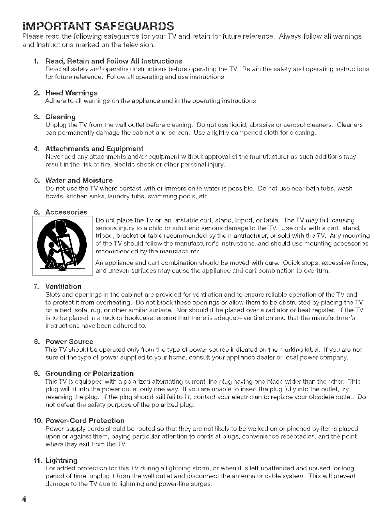
6. Accessories
Do not place the TV on an unstable cart, stand, tripod, or table. The TV may fall, causing
serious injury to a child or adult and serious damage to the TW Use only with a cart, stand,
tripod, bracket or table recommended by the manufacturer, or sold with the TW Any mounting
of the TV should follow the manufacturer's instructions, and should use mounting accessories
recommended by the manufacturer.
An appliance and cart combination should be moved with care. Quick stops, excessive force,
and uneven surfaces may cause the appliance and cart combination to overturn.
7. Ventilation
Slots and openings in the cabinet are provided for ventilation and to ensure reliable operation of the TV and
to protect it from overheating. Do not block these openings or allow them to be obstructed by placing the TV
on a bed, sofa, rug, or other similar surface_ Nor should it be placed over a radiator or heat register. If the TV
is to be placed in a rack or bookcase, ensure that there is adequate ventilation and that the manufacturer's
instructions have been adhered to.
8. Power Source
This TV should be operated only from the type of power source indicated on the marking label. If you are not
sure of the type of power supplied to your home, consult your appliance dealer or local power company.
g.
Grounding or Polarization
This TV is equipped with a polarized alternating current line plug having one blade wider than the other. This
plug will fit into the power outlet only one way. If you are unable to insert the plug fully into the outlet, try
reversing the plug. If the plug should still fail to fit, contact your electrician to replace your obsolete outleL Do
not defeat the safety purpose of the polarized plug.
10. Power-Cord Protection
Power-supply cords should be routed so that they are not likely to be walked on or pinched by items placed
upon or against them, paying particular attention to cords at plugs, convenience receptacles, and the point
where they exit from the TV.
11.
Lightning
For added protection for this TV during a lightning storm, or when it is left unattended and unused for long
period of time, unplug it from the wall outlet and disconnect the antenna or cable system. This will prevent
damage to the TV due to lightning and power-line surges_
4
IMPORTANT SAFEGUARDS, continued
12. Power Lines
An outside antenna system shouHd not be Hocated in the vicinity of overhead power Hinesor other eHectdc Hightor
power circuits, or where it can fall into such power Hinesor circuits. When installing an outside antenna system,
extreme care shouHd be taken to keep from touching such power Hinesor circuits as contact with them might be
fatal.
13. Overloading
Do not overload wall outlets and extension cords as this can result in a risk of fire or electric shock.
14. Object and Liquid Entry
Never push objects of any kind into this TV through openings as they may touch dangerous voltage points or
short-out parts that could result in fire or electric shock. Never spill liquid of any kind on or into the TV.
15.
16.
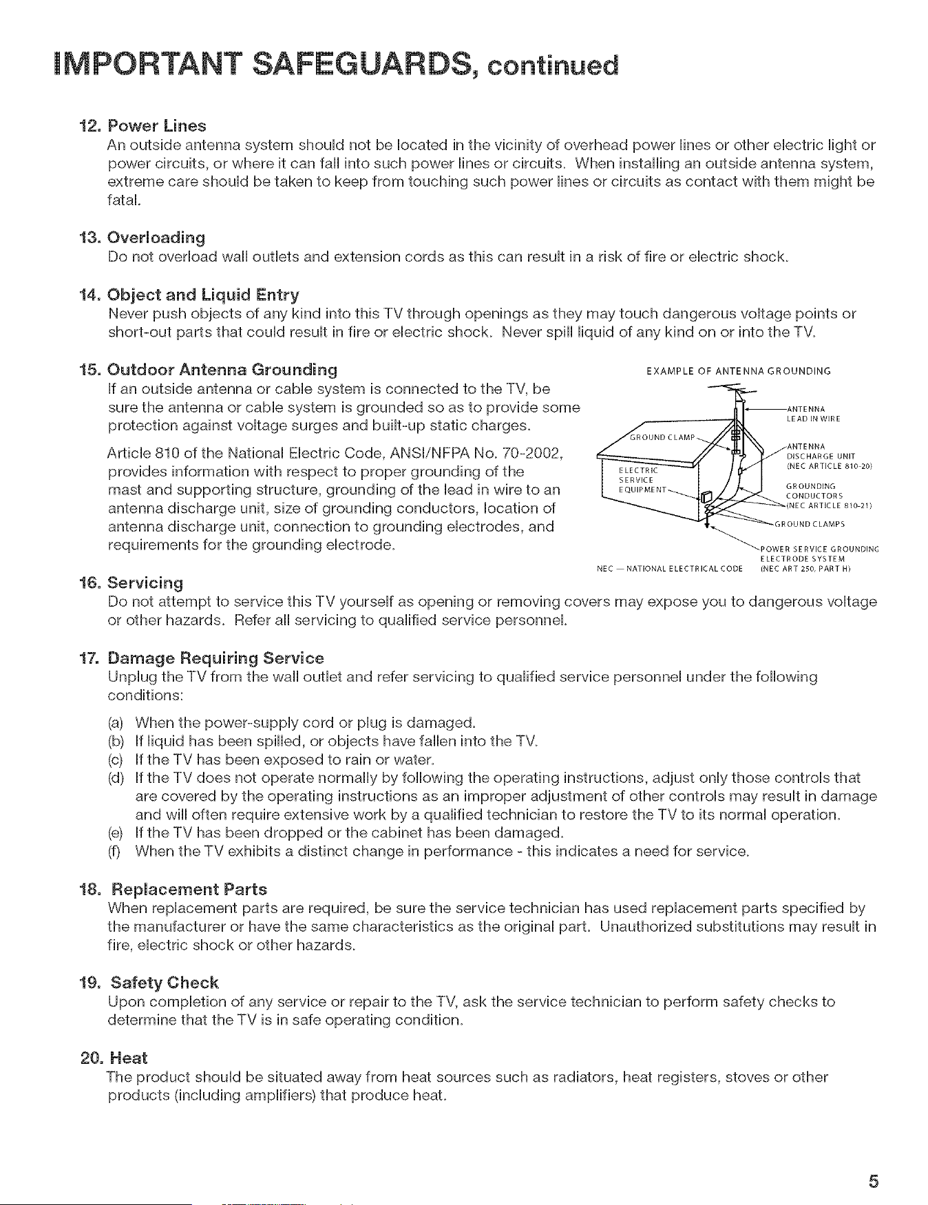
Outdoor Antenna Grounding
If an outside antenna or cable system is connected to the TV, be
sure the antenna or cable system is grounded so as to provide some
protection against voltage surges and built-up static charges.
Article 810 of the National Electric Code, ANSI/NFPA No. 70-2002,
provides information with respect to proper grounding of the
mast and supporting structure, grounding of the lead in wire to an
antenna discharge unit, size of grounding conductors, location of
antenna discharge unit, connection to grounding electrodes, and
requirements for the grounding electrode.
Servicing
EXAMPLE OF ANTENNA GROUNDING
ANTENNA
LEAD IN WIRE
GROUND CLAMP
ANTENNA
DISCHARGE UNIT
(NEC ARTICLE 810 20)
GROUNDING
CONDUCTORS
(NEC ARTICLE 810 21)
OUND CLAMPS
POWER SERVICE GROUNDING
ELECTRODE SYSTEM
NEC NATIONAL E LECTRICAL CODE (NEC ART 250, PART H)
Do not attempt to service this TV yourself as opening or removing covers may expose you to dangerous voltage
or other hazards. Refer all servicing to qualified service personnel.
17.
Damage Requiring Service
Unplug the TV from the wall outlet and refer servicing to qualified service personnel under the following
conditions:
(a) When the power-supply cord or plug is damaged.
(b) If liquid has been spilled, or objects have fallen into the TV.
(c) If the TV has been exposed to rain or water.
(d) If the TV does not operate normally by following the operating instructions, adjust only those controls that
are covered by the operating instructions as an improper adjustment of other controls may result in damage
and will often require extensive work by a qualified technician to restore the TV to its normal operation.
(e) If the TV has been dropped or the cabinet has been damaged.
(f) When the TV exhibits a distinct change in performance - this indicates a need for service.
18.
Replacement Parts
When replacement parts are required, be sure the service technician has used replacement parts specified by
the manufacturer or have the same characteristics as the original part. Unauthorized substitutions may result in
fire, electric shock or other hazards.
19. Safety Check
Upon completion of any service or repair to the TV, ask the service technician to perform safety checks to
determine that the TV is in safe operating condition.
20. Heat
The product should be situated away from heat sources such as radiators, heat registers, stoves or other
products (including amplifiers) that produce heat.
5
Chapter 1: Television Overview
TV Accessories ..................................................................... 10
Special Features .................................................................... 11
Front Control Panel ................................................................. 12
Remote Control
Overview ....................................................................... 14
Battery Installation .............................................................. 15
Care ........................................................................... 15
Sleep Timer ..................................................................... 15
TV Back Panel ...................................................................... 16
Memory Card Reader ............................................................... 18
System Reset Button ................................................................ 20
TV Reset Menu ..................................................................... 20
Chapter 2: Connecting
External Devices and NetCommand® Setup ........................................... 22
Using a CableCARD ................................................................. 23
Wall Outlet Cable ................................................................... 24
Standard Cable Box ................................................................. 24
Antenna with a Single Lead .......................................................... 25
Antennas with Separate UHF and VHF Leads .......................................... 25
VCR to an Antenna or Wall Outlet Cable (Audio & Video) ................................. 26
VCR to a Cable Box (Audio & Video) ................................................... 27
A/V Receiver (Stereo System) ........................................................ 28
Satellite Receiver or Other Device with SWideo ........................................ 28
DVD Player with Component Video ................................................... 29
DVl Device ......................................................................... 29
HDTV Cable Box or Satellite Receiver with Component Video ........................... 30
HDMI Device ....................................................................... 30
Computer with an HDMI Monitor Output ............................................... 31
Computer with a DVI Monitor Output .................................................. 31
IR Emitter NetCommand@ ........................................................... 32
Compatible IEEE 1394 Devices ....................................................... 33
Helpful Hints for NetCommand Connections ........................................... 35
Chapter 3: NetCommand¢:) Setup and Editing
NetCommand® Introduction ......................................................... 38
Using the Remote Control with NetCommand® ........................................ 39
NetCommand® Setup On-Screen Buttons ............................................. 40
3D Graphical _WP0Jn[® Menu System ................................................. 41
NetCommand® Initial Setup ......................................................... 42
Edit NetCommand®: Add an A/V Receiver ............................................ 45
Edit NetCommand®: Add Devices ................................................... 48
Edit NetCommand®: Change or Delete Devices ....................................... 52
IEEE 1394 Devices and NetCommand® Control ........................................ 53
Adding IEEE 1394 Devices Automatically .............................................. 54
Chapter 4: NetCommand® Functions
Device Selection Menu .............................................................. 58
Using the Device Menu Button to Display Menus ....................................... 59
Using the GUIDE Button to Display ChanneIView TM and Menus .......................... 60
NetCommand@-Controlbd Recordings ............................................... 61
Peer-to-Peer Connections ........................................................... 63
Using A/V Discs .................................................................... 64
Chapter 5: TV Menu Operations
Main Menu ......................................................................... 66
Setup Menu ....................................................................... 67
NetCommand@ Menu .............................................................. 69
Record Menu ....................................................................... 70
Channel Menu ..................................................................... 72
Captions Menu ..................................................................... 74
V-Chip Lock Menu .................................................................. 76
Audio/Video Menu .................................................................. 79
Audio Settings ...................................................................... 80
Video Settings ...................................................................... 81
Chapter 6: Additional Features
MediaCommand TM and Memory Card Playback ........................................ 84
Operation of PIP and POP ........................................................... 86
TV Display Formats ................................................................. 87
PC Viewing ......................................................................... 89
PC Display Formats ................................................................. 90
Chapter 7:
Appendices
Appendix
Appendix
Appendix
Appendix
Appendix
Appendix
Appendix
Appendix
Appendix
Troubleshooting ........................................................ 91
A: Specifications ......................................................... 100
B: On-Screen Information Displays ......................................... 102
C: Bypassing the V-Chip Lock ............................................. 103
D: Remote Control Programming Codes .................................... 105
E: Device Control with NetCommand® ..................................... 108
F: NetCommand® Specialized Device Keys ................................. 110
G: Cleaning and Service .................................................. 111
H: Lamp Cartridge Replacement ........................................... 112
k Recording and Viewing Combinations .................................... 114
Trademark and License Information ............................................. 116
Mitsubishi DLP TM Projection Television Limited Warranty .................... 118
Index .................................................................................. 120
Thanks...
Thank you for choosing Mitsubishi as your premier Home Entertainment provider
This Owner's Guide describes the features and functions of your Mitsubishi
widescreen, high definition TV. We urge you to examine this Owner's Guide to
become familiar with the innovative features and operations this unique television
offers.
The very core of our corporate philosophy is to provide our customers with the
very best. Our development team at Mitsubishi has worked to provide you with
a television that defines "state-of-the-art," with the capability to meet your needs
now and in the future.
Whether this is your first Mitsubishi electronic product, or an addition to your
Mitsubishi collection, we believe you and your family will continue to enjoy your
Mitsubishi home theater for many years.
Thank you,
Mitsubishi DigitaJ EJectronics America, Inc.
8
TV Accessories .................................... 10
Special Features .................................... 11
Front Contron Panel .................................. 12
Remote ControU
Overview ........................................ 14
Battery Installation .................................. 15
Care ........................................... 15
Sleep Timer ...................................... 15
TV Back PaneU ..................................... 16
Memory Card Reader ................................ 18
System Reset Button ................................ 20
TV Reset Menu ..................................... 20
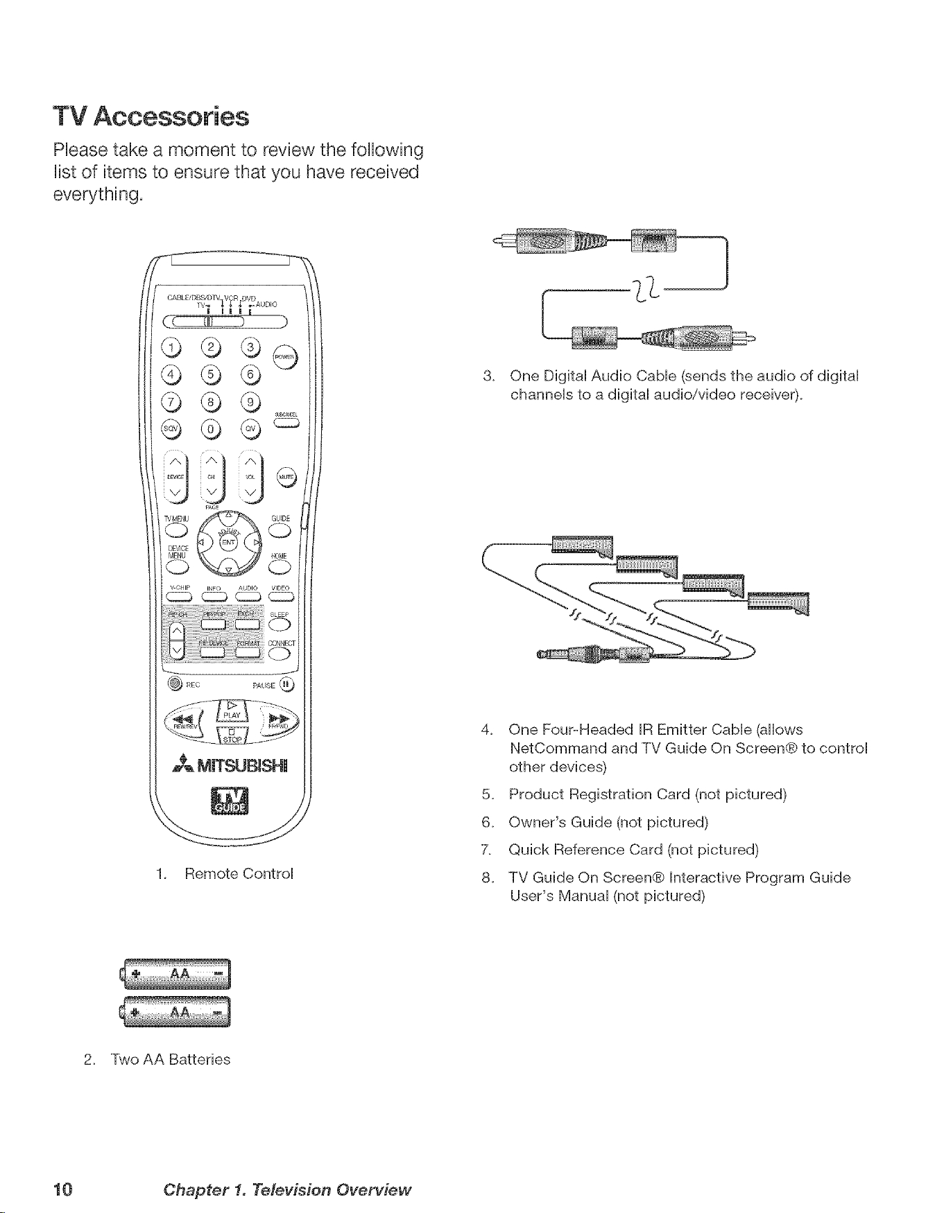
TV Accessories
Phase take a moment to review the following
Uistof items to ensure that you have received
everything.
c_v CHip _ C_ __AUDI° VIDEO
SLEEP
:io
o
PAUSE @
MmT_JBISHU
1. Remote Control
3. One Digital Audio Cable (sends the audio of digital
channels to a digital audio/video receiver).
%
4. One Four-Headed IR Emitter Cable (allows
NetCommand and TV Guide On Screen@ to control
other devices)
5. Product Registration Card (not pictured)
6. Owner's Guide (not pictured)
X Quick Reference Card (not pictured)
8. TV Guide On Screen@ Interactive Program Guide
User's Manual (not pictured)
2. Two AA Batteries
10 Chapter 1. Television Overview
SpeciaJ Features
Your new High Definition widescreen teHevision has many speciaH features that make it the perfect center of your home
entertainment system, incHuding:
High Definition DLP TM DispJay System
Your widescreen MitsubisM HDTV uses Texas hstruments most advanced DigitaH Light Processing TM technoHogy for
rear projection teHevisions. This TV is truHy a high-performance muHfimedia monitor uniqueHy capaMe of both stunning
high-definition video images and clear, detailed, high-resolution PC images. Your TV is able to accept video signals
from an antenna or direct cable in standard video scanning rates of 480i, 480p, 720p, 1080i and 1080p. it is also able
to accept, through the HDMI 2 connection, signals with PC resolutions from VGA (640 x 480) through XGA (1024 x 768).
When used with a compatible graphics card and controlling software, this TV is also able to accept the custom PC
resolution of 720p (1280 x 720). To connect a PCto HDMI 2, you need a PC video card with DVI or HDMI output. Next
you need to perform NetCommand setup for the HDMI 2 PC input so that the TV knows to apply the correct PC-signal
processing. All of the compatible video and PC signals will be converted to 1080p for final display; some signals will,
however, add black side bars, top and bottom bars, or both to fill the screen, and some signals will display standard
video overscan.
TV Guide On Screen@ interactive Program Guide System
An eight-day on-screen program guide that can be used with cable, over-the-air and CableCARD TM reception. The
subscription-free guide system lists regular, digital and high-definition programming. This system allows multiple
sorting options and easy program recording. Program listings are downloaded while your TV is turned off, so that you
have current program information available every day. Note that when the system is first set up, it may take up to 24
hours to begin to receive TV program listings. It may take one week to receive all eight days of TV program listings.
DigitaJ CabJe Ready (CabJeCARD TM}
Your widescreen Mitsubishi HDTV is "Plug-and-Play" ready, it can descramble a cable provider's one-way digital
signals with the use of a CableCARD security module. The CableCARD is used in place of a traditional cable box
to access digital cable programming (including high definition). Contact your local cable provider for availability
information and service details.
NetCommand ® Home Network ControJ System
Your widescreen Mitsubishi HDTV offers a new level of networking to combine selected older products with new and
future digital products. NetCommand supports IEEE 1394 connections, Audio Video Control system (AViC), 5C copy
protection and IR control of selected older products such as VCRs, DVD players, cable boxes or satellite receivers.
NetCommand includes the ability to learn remote control signals directly from many devices, allowing you to customize
the NetCommand system in a way that works best for your viewing
16:9 Widescreen Picture Format
Enjoy a full theatrical experience in the comfort of your home. View pictures as film directors intended them. Digital TV
broadcasts, DVDs and newer video game consoles support this widescreen format.
Memory Card Reader
You can display a slide show of your favorite JPEG pictures or listen to MP3 or WMA audio selections that have been
recorded on compatible memory cards.
Chapter 1. Television Overview 11
Front Controm Panel
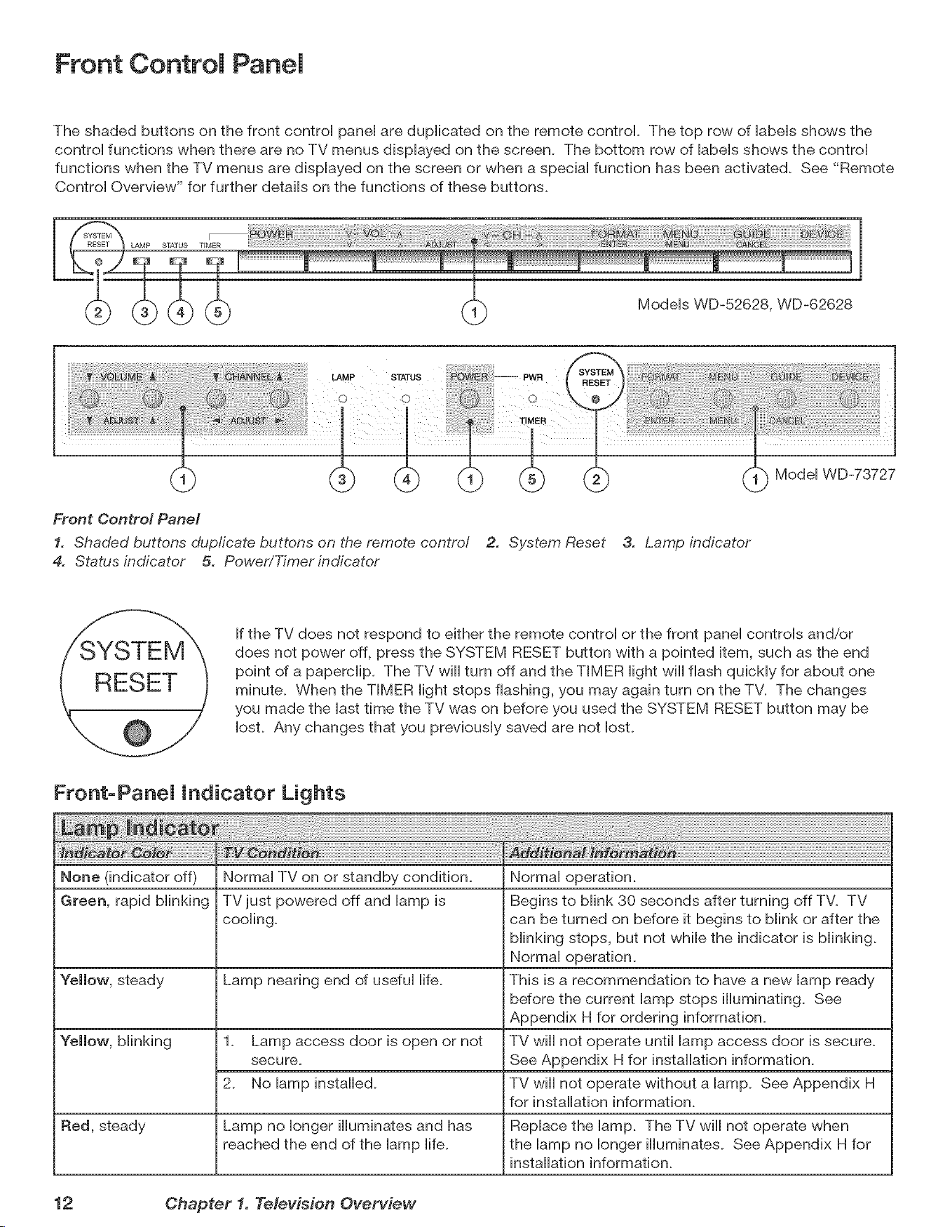
The shaded buttons on the front controi panei are dupiicated on the remote control The top row of iabeis shows the
controi functions when there are no TV menus dispiayed on the screen. The bottom row of iabeis shows the controi
functions when the TV menus are dispiayed on the screen or when a speciai function has been activated. See "Remote
Controi Overview" for further detaiis on the functions of these buttons.
LAMP S_/q'US "rIMER
m
Modeis WD-52628, WD-62628
LAMP
Modei WD-73727
Front Control Panel
1. Shaded buttons dupficate buttons on the remote contro/ 2. System Reset 3. Lamp indicator
4. Status indicator 5. Power/Timer indicator
If the TV does not respond to either the remote controi or the front panei controis and/or
does not power off, press the SYSTEM RESET button with a pointed item, such as the end
point of a paperciip. The TV will turn off and the TIMER light will flash quickly for about one
minute. When the TIMER light stops flashing, you may again turn on the TV. The changes
you made the last time the TV was on before you used the SYSTEM RESET button may be
lost. Any changes that you previously saved are not lost.
Front-PaneJ indicator Lights
None (indicator off)
Green, rapid blinking
Red, steady
Normal TV on or standby condition.
TVjust powered off and lamp is
cooling.
Lamp nearing end of useful life.
1. Lamp access door is open or not
secure.
2. No lamp installed.
Lamp no longer illuminates and has
reached the end of the lamp life.
Normal operation.
Begins to blink 30 seconds after turning off TV. TV
can be turned on before it begins to blink or after the
blinking stops, but not while the indicator is blinking.
Normal operation.
This is a recommendation to have a new lamp ready
before the current lamp stops illuminating. See
Appendix H for ordering information.
TV wiii not operate until lamp access door is secure.
See Appendix H for installation information.
TV wiii not operate without a lamp. See Appendix H
for installation information.
Replace the lamp. The TV will not operate when
the lamp no longer illuminates. See Appendix H for
installation information.
12 Ohapter 1. Television Overview
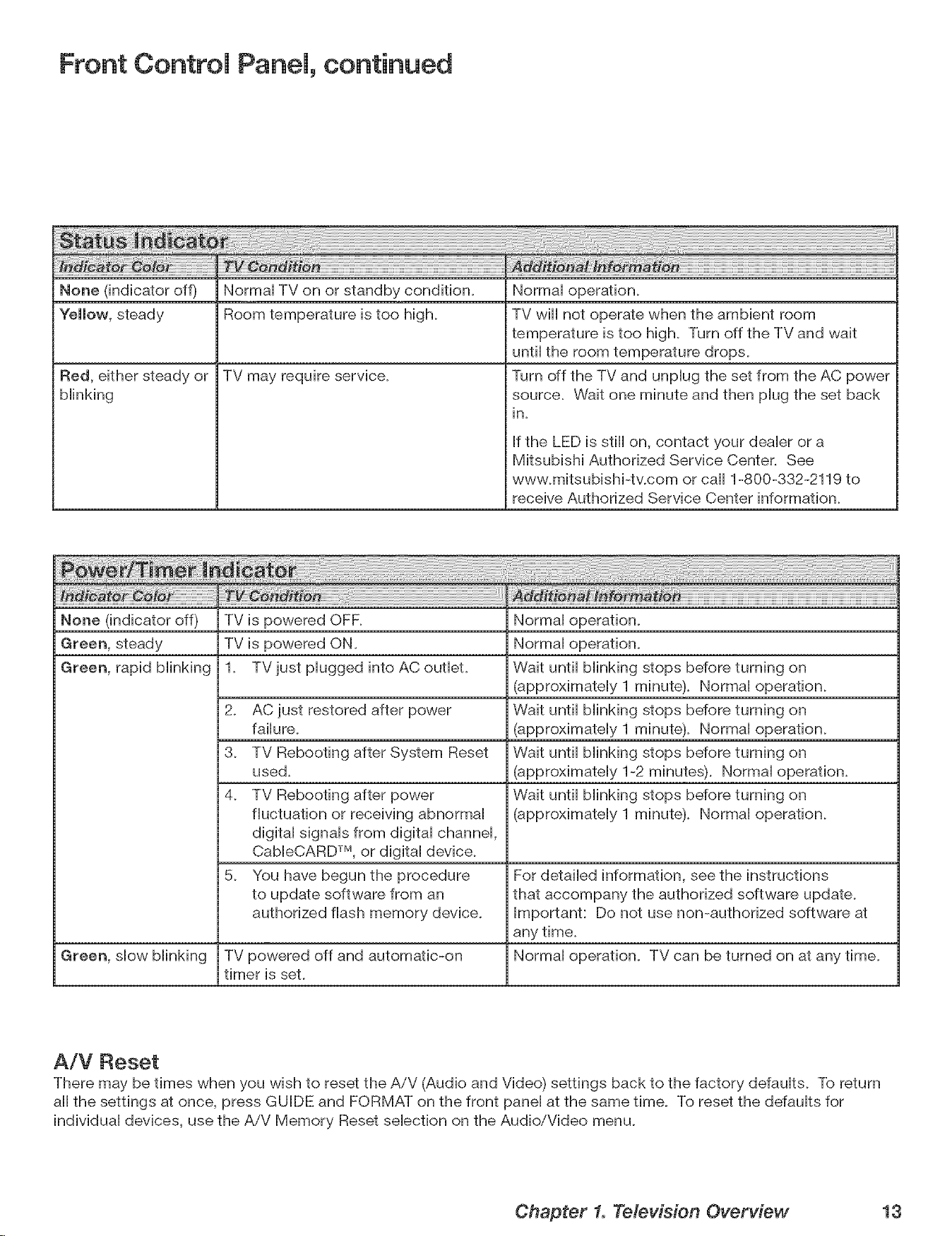
Front Control Panel, continued
None (indicator off) Normal TV on or standby condition.
"follow, stoady Room tomporaturo is too high.
TV may require service.Red, either stoady or
blinking
Normal operation.
TV will not operate when the ambient room
temperature is too high. Turn off the TV and wait
until the room temperature drops.
Turn off the TV and unplug the set from the AC power
source. Wait one minute and then plug the set back
in.
If the LED is still on, contact your dealer or a
Mitsubishi Authorized Service Center. See
www.mitsubishi-tv.com or call 1-800-332-2119 to
receive Authorized Service Center information.
None (indicator off) TV is powered OFF. Normal operation.
Green, steady TV is powered ON. Normal operation.
Green, rapid blinking 1. TV just plugged into AC outlet. Wait until blinking stops before turning on
(approximately 1 minute). Normal operation.
E
2. AC just restored after power Wait until blinking stops before turning on
failure. (approximately 1 minute). Normal operation.
3. TV Rebooting after System Reset Wait until blinking stops before turning on
used. (approximately 1-2 minutes). Normal operation.
4. TV Rebooting after power Wait until blinking stops before turning on
fluctuation or receiving abnormal (approximately 1 minute). Normal operation.
digital signals from digital channel,
CableCARD TM, or digital device.
5. You have begun the procedure For detailed information, see the instructions
to update software from an that accompany the authorized software update.
authorized flash memory device. Important: Do not use non-authorized software at
any time.
Green, slow blinking TV powered off and automatic-on Normal operation. TV can be turned on at any time.
timer is set.
A/V Reset
There may be times when you wish to reset the AiV (Audio and Video) settings back to the factory defaults. To return
all the settings at once, press GUIDE and FORMAT on the front panel at the same time. To reset the ddaults for
individual devices, use the AiV Memory Reset selection on the Audio/Video menu.
Chapter 1. Television Overview 13
Remote Control
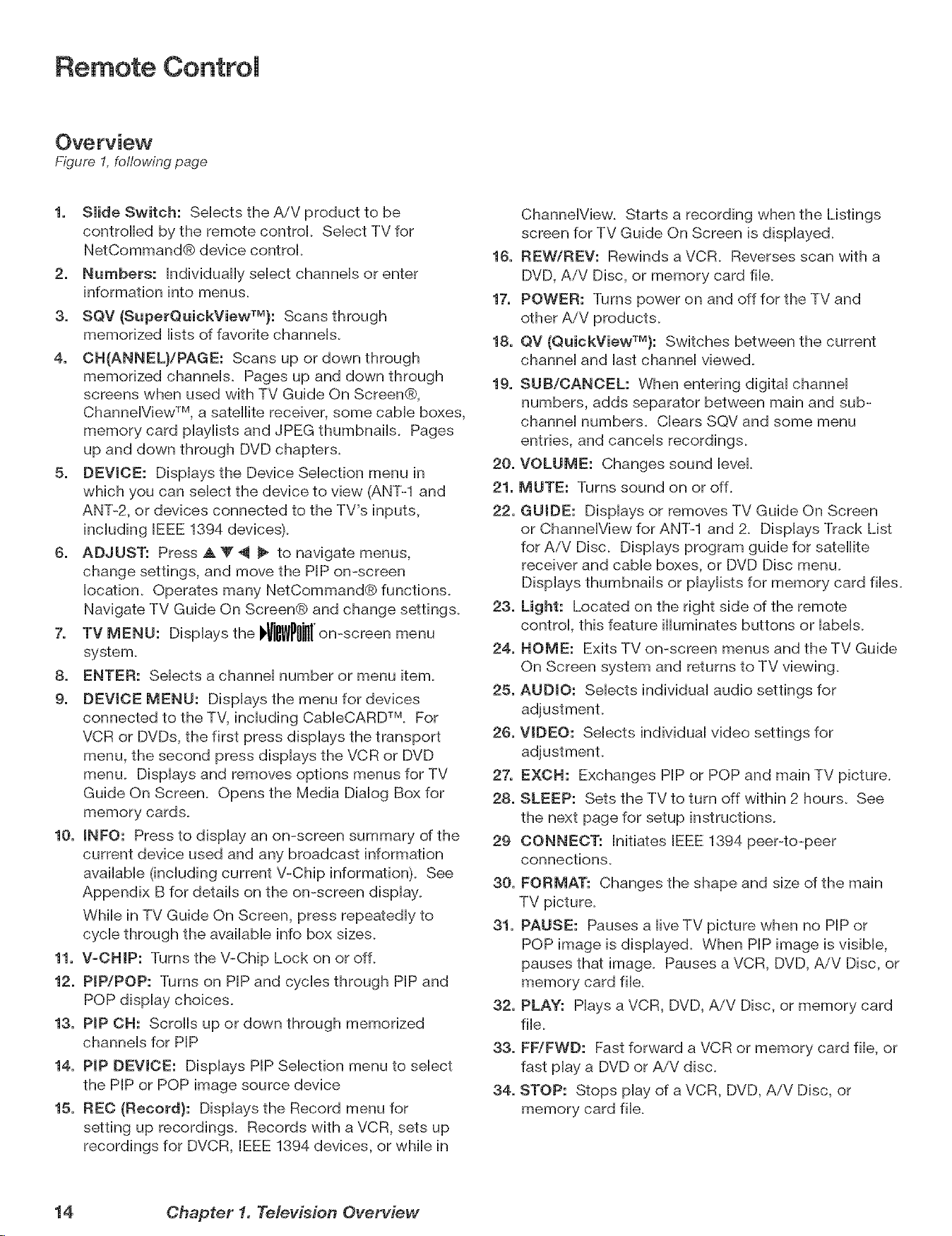
Overview
F/gure 1, following page
1. Slide Switch: Selects the AiV product to be
centre[led by the remote control Select TV for
NetCommand® device centre[.
2. Numbers: Individually select channels or enter
information into menus.
3. SQV (SuperQuickViewTU}: Scans through
memorized lists of favorite channels.
4. CH{ANNEL)/PAGE: Scans up or down through
memorized channels. Pages up and down through
screenswhen used withTV Guide On Screen®,
Channe[ViewTM, a satellitereceiver,some came boxes,
memory card p[ay[istsand JPEG thumbnails.Pages
up and down through DVD chapters.
5, DEVICE: Displaysthe DeviceSelectionmenu in
which you can selectthedeviceto view (ANT-Iand
ANT-2, or devicesconnected totheTV's inputs,
including[EEE 1394 devices).
6. ADJUST: Press A Y _ _ to navigatemenus,
change settings,and move thePIP on-screen
location.Operates many NetCommand® functions.
NavigateTV Guide On Screen® and change settings.
7. TV MENU: Displays the J WPIIilIIon-screenmenu
system.
8. ENTER: Selects a channel number or menu item.
9. DEVICE MENU: Displays the menu for devices
connected to the TV, including Cab[eCARD TM. For
VCR or DVDs, the first press displays the transport
menu, the second press displays the VCR or DVD
menu. Displays and removes options menus for TV
Guide On Screen. Opens the Media Dialog Box for
memory cards.
10. INFO: Press to display an on-screen summary of the
current device used and any broadcast information
available (including current V-Chip information). See
Appendix B for details on the on-screen display.
While in TV Guide On Screen, press repeatedly to
cycle through the available info box sizes.
11. V-CHIP: Turns the V-Chip Lock on or off.
12. PIP/POP: Turns on PIP and cycles through PIP and
POP display choices.
13. PIP CH: Scrolls up or down through memorized
channels for PIP
14. PIP DEVICE: Displays PIP Selection menu to select
the PIP or POP image source device
15. REC {Record}: Displays the Record menu for
setting up recordings. Records with a VCR, sets up
recordings for DVCR, [EEE 1394 devices, or while in
Channe[View. Starts a recording when the Listings
screen for TV Guide On Screen is displayed.
16. REW/REV: Rewinds a VCR. Reverses scan with a
DVD, AiV Disc, or memory card file.
17. POWER: Turns power on and off for the TV and
other AiV products.
18, QV {QuickViewTU}: Switches between the current
channel and last channel viewed.
19. SUB/CANCEL: When entering digital channel
numbers, adds separator between main and sub-
channel numbers. Clears SQV and some menu
entries, and cancels recordings.
20. VOLUME: Changes sound [eve[.
21. MUTE: Turns sound on or off.
22. GUIDE: Displays or removes TV Guide On Screen
or Channe[View for ANT-1 and 2. Displays Track List
for AiV Disc. Displays program guide for satellite
receiver and came boxes, or DVD Disc menu.
Displays thumbnails or p[ay[ists for memory card files.
23. Light: Located on the right side of the remote
control this feature illuminates buttons or labels.
24. HOME: Exits TV on-screen menus and the TV Guide
On Screen system and returns to TV viewing.
25. AUDIO: Selects individual audio settings for
26. VIDEO: Selects individual video settings for
27. EXCB: Exchanges PIP or POP and main TV picture.
28. SLEEP: Sets the TV to turn off within 2 hours. See
the next page for setup instructions.
29 CONNECT: Initiates [EEE 1394 peer-to-peer
connections.
30. FORMAT: Changes the shape and size of the main
TV picture.
31. PAUSE: Pauses a live TV picture when no PIP or
POP image is displayed. When PIP image is visible,
pauses that image. Pauses a VCR, DVD, AiV Disc, or
memory card file.
32. PLAY: Hays a VCR, DVD, AiV Disc, or memory card
file.
33. FF/FWB: Fast forward a VCR or memory card file, or
fast play a DVD or A/V disc.
34. STOP: Stops play of a VCR, DVD, AiV Disc, or
memory card file.
14 Chapter 1. Television Overview
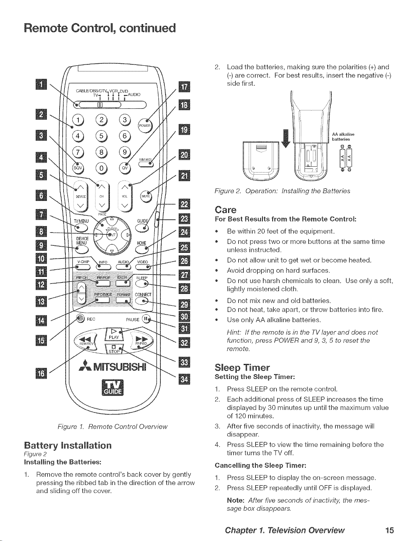
Remote Controm, continued
PAGE
REC PAUSE
Figure I. Remote Control Overview
Battery installation
Figure 2
1. Remove the remote controH's back cover by gently
pressing the ribbed tab in the direction of the arrow
and sHiding off the cover.
2. Load the batteries, making sure the poHarifies (+) and
(-) are correcL For best resuHts, insert the negative (-)
side firsL
AA aUkaUine
batteries
Figure 2. Operation: /nsta//ing the Batteries
Care
For Best Results from the Remote Control:
Be within 20 feet of the equipment.
Do not press two or more buttons at the same time
unless instructed.
Do not allow unit to get wet or become heated.
Avoid dropping on hard surfaces.
* Do not use harsh chemicals to clean. Use only a soft,
lightly moistened cloth.
Do not mix new and old batteries.
* Do not heat, take apart, or throw batteries into fire.
* Use only AA alkaline batteries.
Hint: If the remote is in the TV layer and does not
function, press POWER and 9, 3, 5 to reset the
remote.
SJeep Timer
Setting the Sleep Timer:
1. Press SLEEP on the remote control.
2. Each additional press of SLEEP increases the time
displayed by 30 minutes up until the maximum value
of 120 minutes.
3. After five seconds of inactivity, the message will
disappear.
4. Press SLEEP to view the time remaining before the
timer turns the TV off.
Cancelling the Sleep Timer:
1. Press SLEEP to display the on-screen message.
2. Press SLEEP repeatedly until OFF is displayed.
Note: After five seconds of inactivity, the mes-
sage box disappears.
Chapter 1. Television Overview 15
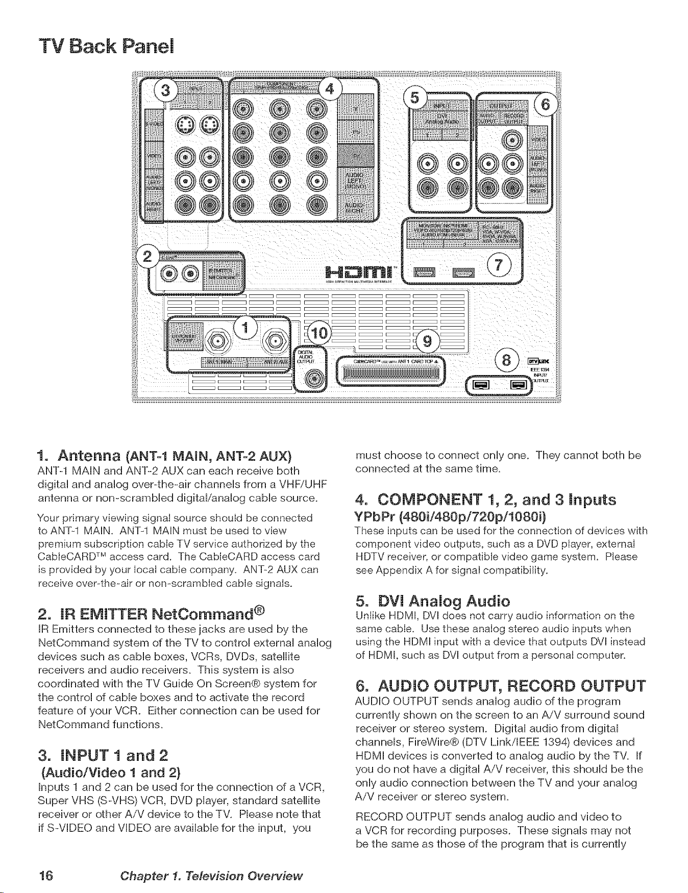
TV Back Panel
1. Antenna (ANT-1 MAIN, ANT-2 AUX}
ANT-1 MAIN and ANT-2 AUX can each receive both
digita] and anaiog over-the-air channeis from a VHFiUHF
antenna or non-scrambled digital/analog cable source.
Your primary viewing signal source should be connected
to ANT-1 MAIN. ANT-I MAIN must be used to view
premium subscription cable TV service authorized by the
CabteCARD TM access card. The CableCARD access card
is provided by your Iocat cable company. ANT-2 AUX can
receive over-the=air or non-scrambled cable signals.
2. IR EMITTER NetCommand ®
IR Emitters connected to these jacks are used by the
NetCommand system of the TV to control external analog
devices such as cable boxes, VCRs, DVDs, satellite
receivers and audio receivers. This system is also
coordinated with the TV Guide On Screen@ system for
the control of cable boxes and to activate the record
feature of your VCR. Either connection can be used for
NetCommand functions.
3. INPUT 1 and 2
(Audio/Video 1 and 2}
Inputs 1 and 2 can be used for the connection of a VCR,
Super VHS (S-VHS) VCR, DVD player, standard satellite
receiver or other A/V device to the TV. Please note that
if S-VIDEO and VIDEO are available for the input, you
must choose to connect only one. They cannot both be
connected at the same time.
4. COMPONENT 1, 2, and 3 Inputs
YPbPr (480i/480p/720pi1080i}
These inputs can be used for the connection of devices with
component video outputs, such as a DVD piayer, externaI
HDTV receiver, or compatible video game system. Please
see Appendix A for signal compatibility.
5. DVl AnaJog Audio
Uniike HDMI, DVl does not carry audio information on the
same cable. Use these analog stereo audio inputs when
using the HDMI input with a device that outputs [}"71instead
of HDMI, such as DVl output from a personal computer.
6. AUDIO OUTPUT, RECORD OUTPUT
AUDIO OUTPUT sends analog audio of the program
currently shown on the screen to an A/V surround sound
receiver or stereo system. Digital audio from digital
channels, FireWire@ (DTV LinkiEEE 1894) devices and
HDMI devices is converted to analog audio by the TV. If
you do not have a digital A/V receiver, this should be the
only audio connection between the TV and your analog
AiV receiver or stereo system.
RECORD OUTPUT sends analog audio and video to
a VCR for recording purposes. These signals may not
be the same as those of the program that is currently
16 Chapter 1. Television Overview
TV Back Panel, continued
being shown on screen. Signals from digital channels
and FireWire (IEEE 1394) devices are converted to analog
signals. There is no video signal when copy restrictions
are in effect. Audio alone is output when a Component
input or the HDMI input is selected for recording.
7. HDMI TM 1 and 2
The HDMI (High Definition Multimedia Interface) supports
uncompressed standard and high-definition digital video
formats and PCM digital audio format.
Use these inputs to connect to EIA/CEA-861 compliant
devices such as a high-definition receiver or DVD player.
These inputs support 480i, 480p, 720p and 1080i video
formats.
These inputs can also be used as a DVI connection with
separate analog audio inputs. An optional HDMPto-DVI
adaptor or cable is necessary to make this connection
and may be available from your local electronics retailer.
When using the optional HDMPto-DVI adapter, the DVI
analog audio inputs on your TV allow you to receive left
and right audio from your DVI device.
This input is HDCP (High-Bandwidth Digital Copy
Protection) compiianL
HDMI 2
HDMI 2 aiso aiiows the TV to display DVI or HDMI output
from a PC. To view PC video on the TV, you must activate
the PC option in NetCommand. You can do this during
initial NetCommand setup by selecting the PC option
in the Device Setup screen. To do this at any time
afterwards, use the NetCommand Add function.
To listen to audio from a PC when using PC DVI output,
you must connect the PC audio output to the TV's DVI
Analog Audio 2, located above the HDMI 2 inpuL
8. DTV LinkTM/IEEE 1394
These jacks allow the TV to connect to external IEEE 1394
digital products by means of a single cable. Two jacks
are provided for this purpose, which allow for a high
degree of flexibility for connecting your NetCommand
controlled system. Detailed information regarding
IEEE 1394 connection requirements is in Chapter 2,
9, CabJeOARD TM SJot
The CableCARD access card from your cable TV service
provider is inserted into this sloL The top of the card
should face in the direction indicated by CARD TOP ,A.
CableCARD is a nationwide standard system that allows
your local cable TV provider to supply you with an
access card customized to your account. This card
allows the TV to receive, decode and unscramble the
premium digital channels included in your cable TV
subscription without the use of a cable box. See page
23 for additional CableCARD information and activation
instructions.
If your cable company is not currently offering
CableCARD access cards, you will need to use a
cable box provided and authorized by your local cable
company to view scrambled channels.
10. DigitaJ Audio Output
This output sends Dolby@ Digital or PCM digital audio to
your digital A/V surround sound receiver. Analog audio
from analog channels and devices is converted by the
TV to PCM digital audio. In most cases, this should be
the only audio connection between the TV and your AiV
receiver. If you have MP3 audio from memory cards,
however, you need to connect the TV's analog AUDIO
OUTPUT (left and right) to your AiV receiver.
Chapter 1. Television Overview 17
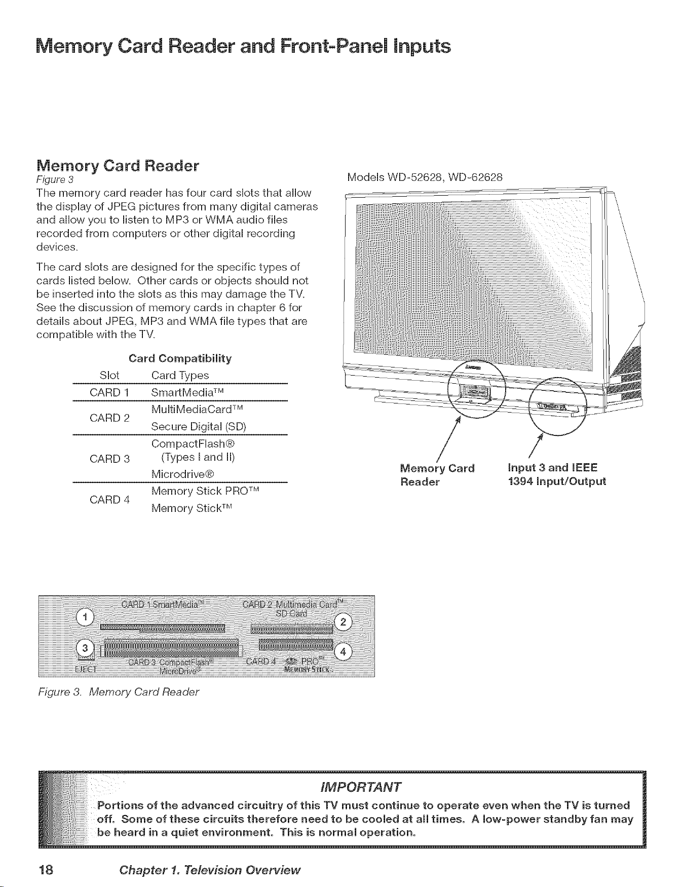
Memory Card Reader and Front-Panel Inputs
Memory Card Reader
Figure 3
The memory card reader has four card shots that allow
the display of JPEG pictures from many digital cameras
and allow you to listen to MP3 or WMA audio flies
recorded from computers or other digital recording
devices.
The card shots are designed for the specific types of
cards listed below. Other cards or objects should not
be inserted into the shots as this may damage the TV.
See the discussion of memory cards in chapter 6 for
details about JPEG, MP3 and WMA file types that are
compatible with the TV.
Card Compatibility
SHot Card Types
CARD 1 SmartMedia TM
Mu[tiMediaCard TM
CARD 2
Secure Digital (SD)
CompactF[ash®
CARD 3 (Types [ and [[)
Microdrive®
Memory Stick PROTM
CARD 4
Memory Stick TM
Models WD-52628, WD-62628
/
Memory Card
Reader
Figure 3. Memory Card Reader
18 Chapter f. Television Overview
Memory Card Reader and FrontoPanei Inputs
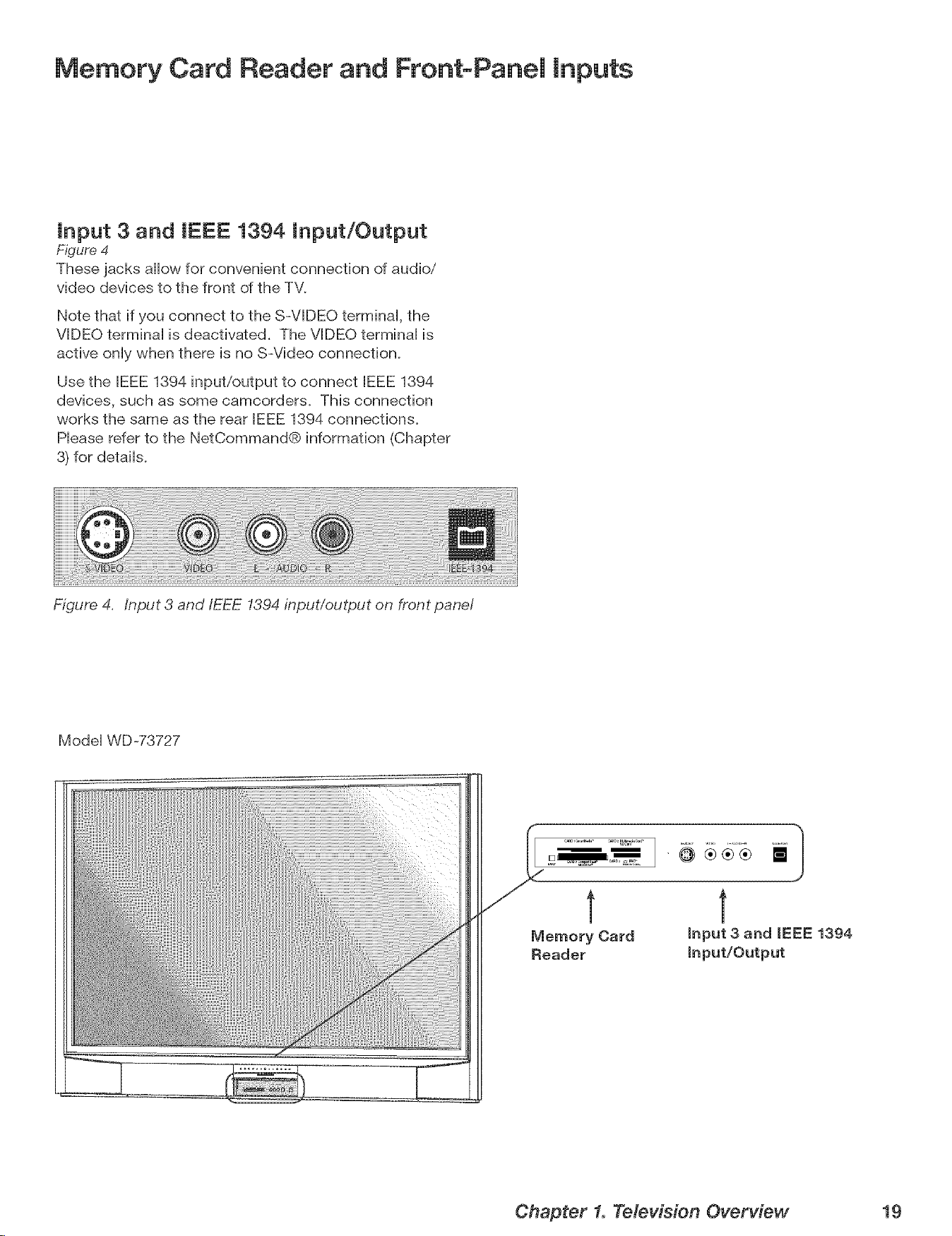
input 3 and IEEE 1394 input/Output
Figure 4
These jacks allow for convenient connection of audio/
video devices to the front of the TV.
Note that if you connect to the S-VIDEO terminaH, the
VIDEO terminaH is deactivated. The VIDEO terminaH is
active onHywhen there is no S-Video connection.
Use the IEEE 1394 input/output to connect IEEE 1394
devices, such as some camcorders. This connection
works the same as the rear IEEE 1394 connections.
Hease refer to the NetCommand® information (Chapter
3) for details.
Figure 4. input 3 and/EEE 1394 input/output on front panel
Model WD-73727
Chapter 1. Television Overview 19
Additional Information
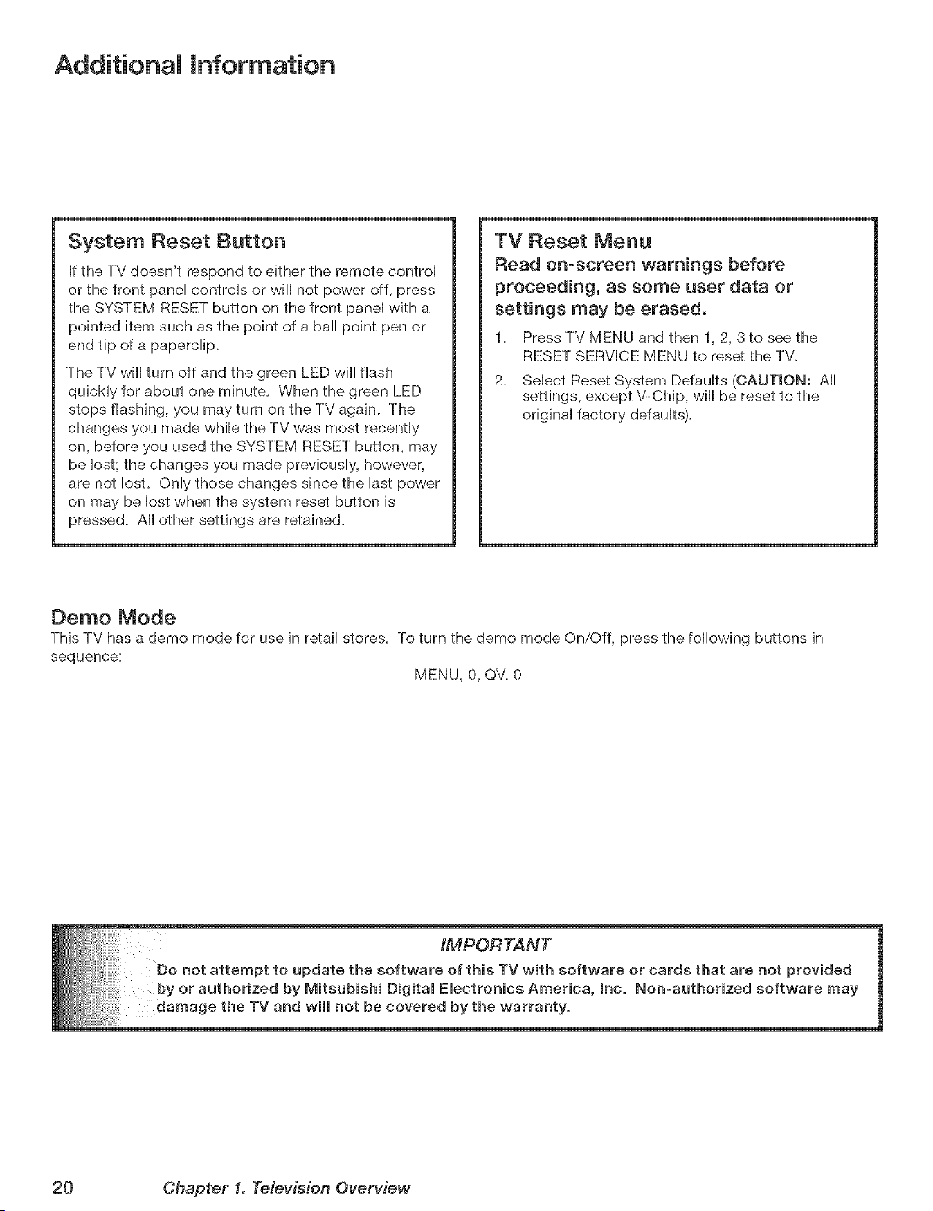
System Reset Button
if the TV doesn't respond to either the remote control
or the front panel controls or will not power off, press
the SYSTEM RESET button on the front panel with a
pointed item such as the point of a ball point pen or
end tip of a paperdip,
The TV will turn off and the green LED will flash
quickly for about one minute. When the green LED
stops flashing, you may turn on the TV again. The
changes you made while the TV was most recently
on, before you used the SYSTEM RESET button, may
be lost; the changes you made previously, however,
are not lost. Only those changes since the last power
on may be lost when the system reset button is
pressed. All other settings are retained.
TV Reset Menu
Read on-screen warnings before
proceeding, as some user data or
settings may be erased.
1. Press TV MENU and then 1, 2, 3to see the
RESET SERVICE MENU to reset the TV.
2. Select Reset System Defaults (OAUTWON: All
settings, except V-Chip, will be reset to the
original factory defaults).
Oemo Mode
This TV has a demo mode for use in retail stores. To turn the demo mode On/Off, press the following buttons in
sequence:
MENU, 0, QV, 0
20 Chapter f. Television Overview
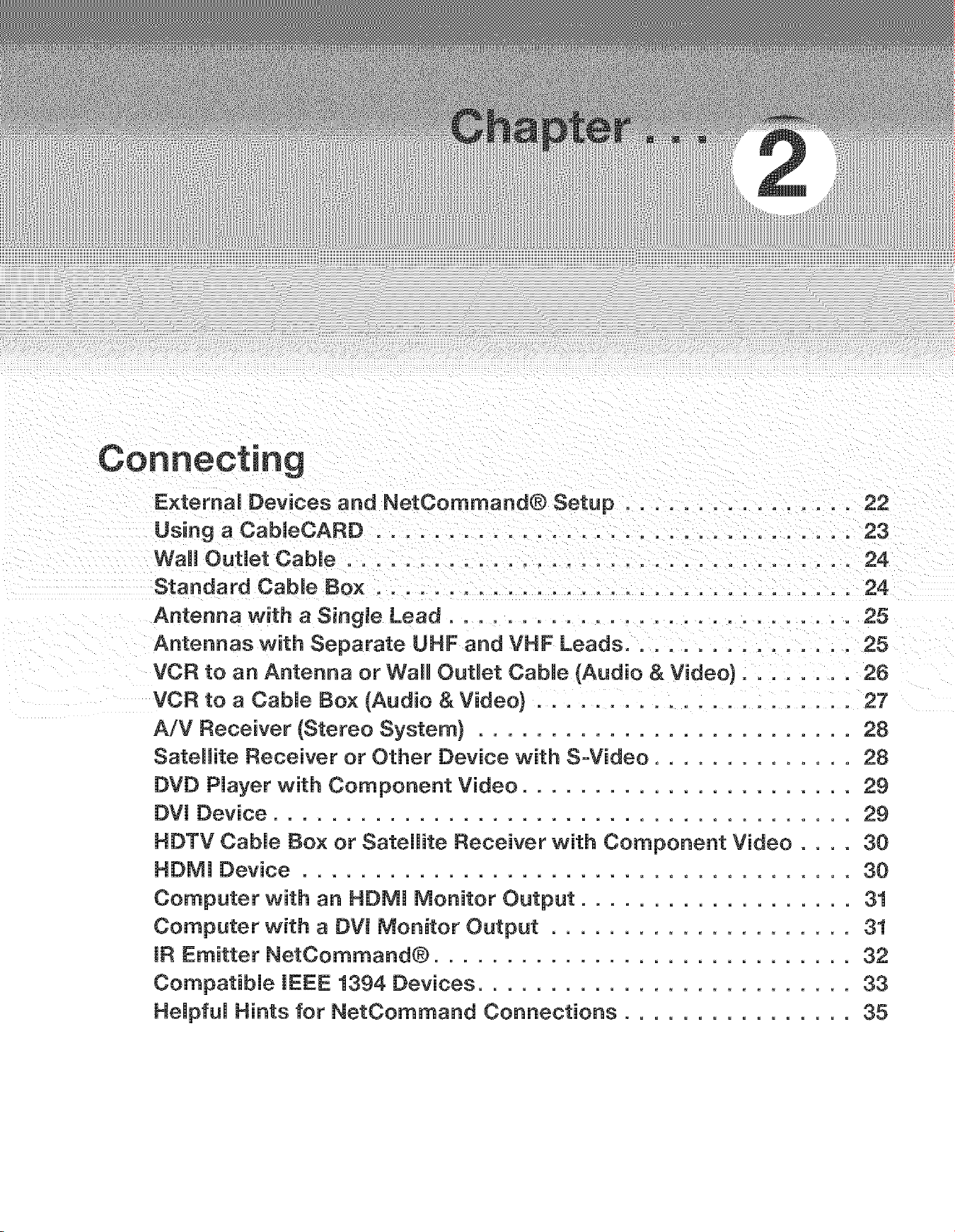
E×temaU Devices and NetCommand® Setup ................ 22
Using a CabUeCARD ................................. 23
Wall Outlet Cable ................................... 24
Standard CabUe Box ................................. 24
Antenna with a Singme Lead ............................ 25
Antennas with Separate UHF and VHF Leads ............... 25
VCR to an Antenna or Wall OutUet CabUe (Audio & Video) ........ 26
VCR to a CabJe Box (Audio & Video} ...................... 27
A/V Receiver (Stereo System} .......................... 28
Satellite Receiver or Other Device with S-Video .............. 28
DVD PJayer with Component Video ....................... 2g
DVI Device ........................................ 2g
HDTV CabJe Box or Satellite Receiver with Component Video .... 30
HDMI Device ...................................... 30
Computer with an HDMI Monitor Output ................... 31
Computer with a DW Monitor Output ..................... 31
IR Emitter NetCommand® ............................. 32
CompatibJe IEEE 1394 Devices .......................... 33
HeJpfuJ Hints for NetCommand Connections ................ 35
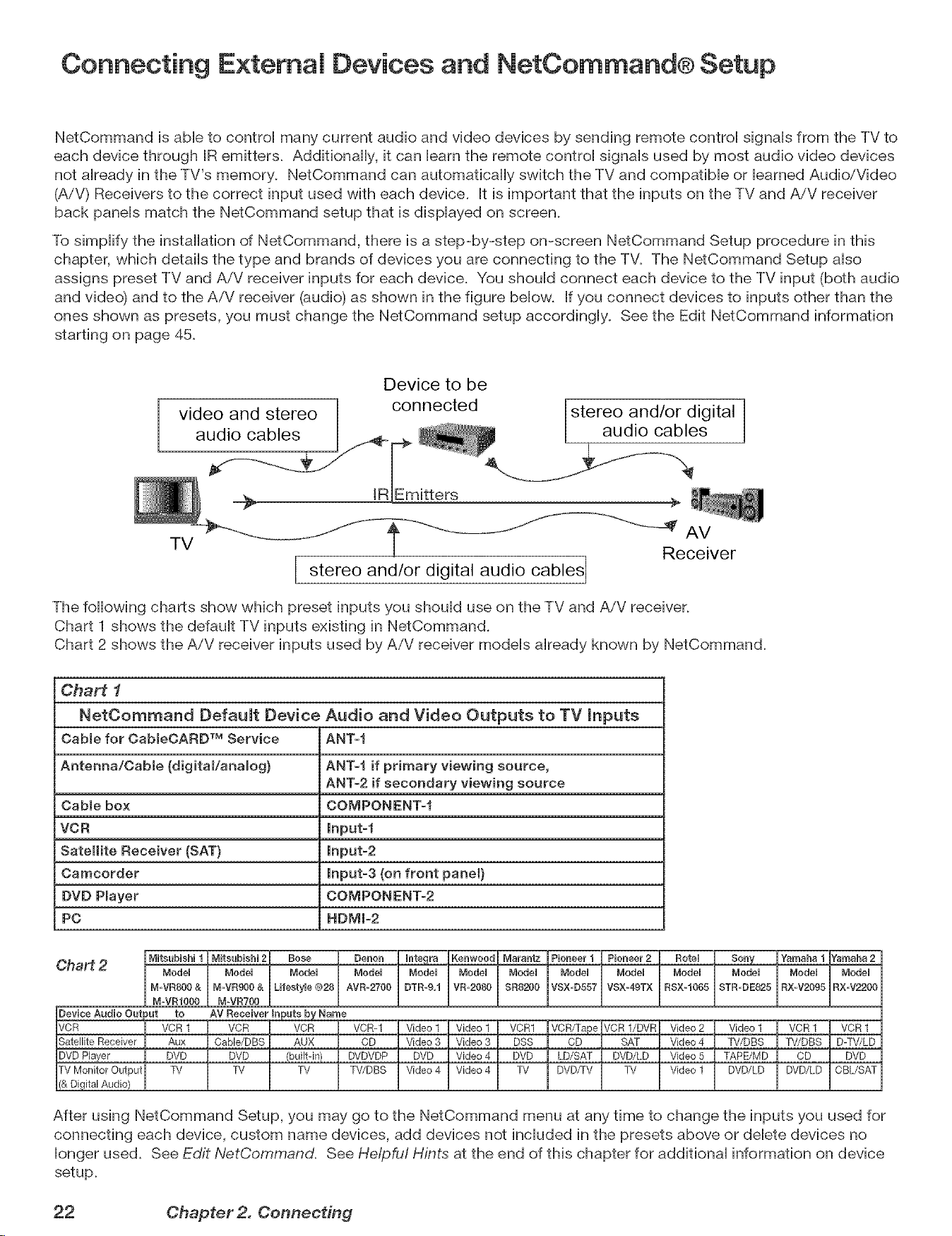
Connecting E×temai Devices and NetCommand® Setup
NetCommand is able to control many current audio and video devices by sending remote control signals from the TV to
each device through IR emitters. Additionally, it can barn the remote control signals used by most audio video devices
not already in the TV's memory. NetCommand can automatically switch the TV and compatible or learned Audio/Video
(A/V) Receivers to the correct input used with each device. It is important that the inputs on the TV and AiV receiver
back panels match the NetCommand setup that is displayed on screen.
To simplify the installation of NetCommand, there is a step-by-step on-screen NetCommand Setup procedure in this
chapter, which details the type and brands of devices you are connecting to the TV. The NetCommand Setup also
assigns preset TV and AiV receiver inputs for each device. You should connect each device to the TV input (both audio
and video) and to the AiV receiver (audio) as shown in the figure below. If you connect devices to inputs other than the
ones shown as presets, you must change the NetCommand setup accordingly. See the Edit NetCommand information
starting on page 45.
Device to be
Lstereo and/or digital
audio cables i
AV
TV Receiver
I stereo and/or audio cables
digital
The following charts show which preset inputs you should use on the TV and AiV receiver.
Chart 1 shows the default TV inputs existing in NetCommand.
Chart 2 shows the AiV receiver inputs used by AiV receiver models already known by NetCommand.
Chart 1
NetOommand Default Device Audio and Video Outputs to TV inputs
Cable for CabmeOARDTM Service ANT-f
Antenna/Oabme (digitaVanamog} ANT-I if primary viewing source,
ANT-2 if secondary viewing source
Cable box COMPONENT_f
VCR lnput-f
Satellite Receiver (SAT} Input-2
Camcorder Input-3 (on front panel}
DVD Pmayer COMPONENTs2
PC HDMI=2
Chart 2
After using NetCommand Setup, you may go to the NetCommand menu at any time to change the inputs you used for
connecting each device, custom name devices, add devices not included in the presets above or delete devices no
longer used. See Edit NetCommand. See He/pfu! Hints at the end of this chapter for additional information on device
setup.
22 Chapter2. Connecting
Using a CabieCARD
Using a CabJeCARD
After inserting a CaMeCARD into the TV back
panel CableCARD slot and powering On the TV, the
initialization process begins. An initial screen wiii
automatically display for a few minutes, with information
that your Cable Provider wiii need in order to start
service. Please write down this information before calling
your cable provider.
Ptease call XYZ CabLe
a_ xxx-xx×-xxxx to
actwate cable service.
The_ wm neea inese rlumbers:
Host ID X-XXX-XXX-XXX-XXX
CableCARD TMID: X-XXX-XXX-XXX-XXX
See owner's manual fo_
further information
An example of an initial screen is shown here. Your
screen wiii display specific information from your cable
provider and may not look like this screen.
If you were unable to record the information, you can
press TV MENU on the remote and then enter the
number 999 and the screen will re-display. You can
also press DEVICE MENU when the CableCARD is the
selected source and you will be able to select the startup
application.
iMPORTANT
e a CableOARD, the primary incoming
CabJeOARD TechnoJogy
CableCARD is a nationwide system standard that allows
your local cable TV provider to supply you with an access
card customized to your account. This card allows your
TV to receive, decode and unscramble the premium
digital channels included in your cable TV subscription
without the use of a cable box. It also allows your
cable provider to automatically update and change your
subscription. When you move to a new cable provider's
area, you simply return the CableCARD to the original
cable provider and get a new card from your new cable
provider_
Please note that CableOARD is a new technology and
your local cable provider may not currently be offering
this service. As time passes, this system wiii become
broadly supported by most cable providers.
The CableCARD system is "unidirectional" which means
your cable provider can send updates to the access
card and TV, however, the TV cannot send back signals
such as requests for Video-On-Demand or Pay-per-View
programs by remote control
Digital cable channels authorized by the CableCARD
wiii be available on the Firewire® IEEE 1394 network
and can be shared by other products on the networL
Some digital channels or programs may not be copied
or recorded because of copy restriction limits set by the
content owners or copyright holders_
The digital television is capable of receiving analog
basic, digital basic, and digital premium cable
television programming by direct connection to a
cable system providing such programming. A security
card (CabieCARD) provided by your cable operator is
required to view encrypted digital programming. Certain
advanced and interactive digital cable services, such as
video-on-demand, a cable operator's enhanced program
guide, and data-enhanced television services, may
require the use of a set-top box. For more information,
call your local cable operator.
Please see page 17 for instructions on how to insert the
CabieCARD.
Chapter 2. Connecting 23
Connecting a Wail Outlet Cable or Cable Box
Wail Outlet Cable
(can be used with a CabmeCARD TM)
F_gure1
It is very important to connect the incoming came
for your primary viewing source to ANT-l, especiaHHy
for CabHeCARDTM use and to downHoad TV Guide On
Screen® Hisfings.
2.
3.
Connect the primary incoming coaxiaH Headcame to
ANT l/MAIN on the TV back pane[.
For an optional secondary antenna source, connect
an antenna (or cable) to ANT 2/AUX.
If you have subscribed to a CabHeCARDTM service,
the CabHeCARD can now be inserted into the
CabHeCARD SLOT. Using a Phillips screwdriver,
remove the CabHeCARD cover screws. Insert the
CabHeCARD, then replace the cover and screws. The
top of the card should face in the direction the CARD
TOP arrow indicates.
Additional CabHeCARD information is on page 23.
Detailed TV Guide On Screen information is in the
separate User's Manual.
Standard Cable Box
(cabUebox, other than an HDTV cabmebox; this setup
allows two-channel PIP)
Figure 2
3 coaxial cables and one two-way RF splitter are required.
Theseare not included with the TV.
Note: See page 30 to connect an HDTV came box.
1. Connect the incoming came to IN on an RF spHitter.
2. Connect one coaxiaH came from OUT on the RF
spHitter to ANT-1 MAiN on the TV back pane[.
3. Connect one coaxiaH came from OUT on the RF
spHitter to IN on the standard came box.
4. Connect one coaxiaH came from OUT on the came
box to ANT-2 AUX on the TV back pane[.
5. After the came box is connected to ANT-2 AUX as
shown, use the NetCommand menu Change option
to change the defauHt connection for the came box,
go to the RF Connection for CaMe screen and do the
foHHowing:
a. Check the RF check box.
b. For antenna, seHect ANT-2.
c. For ChanneH, seHect the channeH to which the TV
must be tuned for your came box. The defauHt
channeH is 3.
When this setup is compHete, you can use the TV remote
controH to change channeHs on the came box.
ii!ii_ii!!i_i_i:!iiiiii:,¸ i _ _i::,!i!!ji!::i:i:i!_ii!!i?!_!i!_¸lii_¸¸
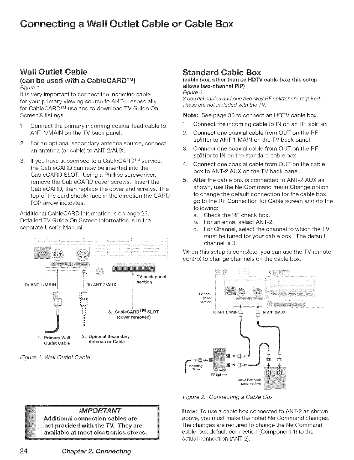
3. Cab_eOARD TM SLOT
(cover removed}
1. Primary Wall
Outlet Cable
2. Optional Secondary
Antenna or CabEe
Figure I. Waft Outlet CaMe
__h the TV. They are
TV back
paneH
section
To ANT 2!AUX
E booming -'_
Figure 2. Connecting a CaMe Box
Note: To use a cable box connected to ANT-2 as shown
above, you must make the noted NetCommand changes.
The changes are required to change the NetCommand
cabie_box default connection (Componentq) to the
actual connection (ANT-2).
24 Chapter 2. Connecting
Connecting an Antenna with a Single Lead or Antennas with
Separate UHF and VHF Leads
Antenna with a SingJe Lead
(not for use with Cab[eCARDTM)
Figure 3
For antennas with flat twin leads
A 300-ohm-to-Z5-ohm transformer is required. This is not
included with the TV, but is available at most electronics stores.
1. For an antenna with fiat twin Heads,connect the
300-ohm twin Headsto the 300-ohm-to-75-ohm
transformer.
2. Push the 75-ohm side of the transformer onto ANT-1
MAiN on the TV back panel
For cable or antenna with coaxial lead
Connect the coaxiaH HeaddirectHy to ANT-1 MAiN on
the TV back panel
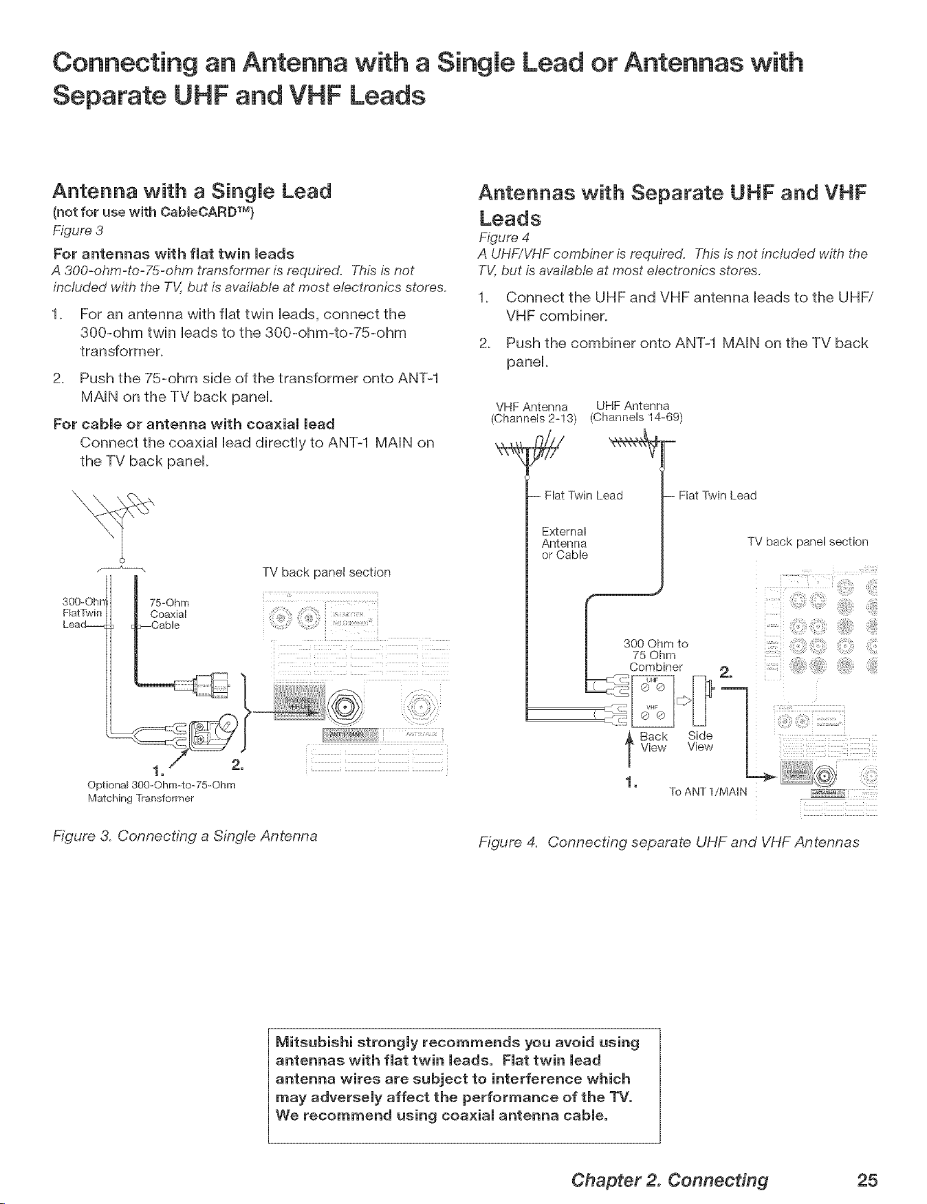
300-Ohrr
natTwin
Lead_
75=Ohm
Coaxial
Cable
TV back panel section
i
i
1, 2,
Optiona_ 300=Ohrn=to-75-Ohm
Matching Transformer
Figure 3. Connecting a Single Antenna
Antennas with Separate UHF and VHF
Leads
Figure 4
A UHF/VHF combiner is required. T,_isis not included with the
TV,but is available at most electronics stores.
1_ Connect the UHF and VHF antenna leads to the UHFi
VHF combiner.
2_ Push the combiner onto ANT-1 MAIN on the TV back
panel_
VHF Antenna UHF Antenna
(Channels 2=13) (Channels 14=69)
- Flat Twin Lead
External
Antenna
or Cable
-- Flat Twin Lead
TV back panel section
300Ohmto, iiliiiii
75 Ohm
Combiner 2.
__ Sack SideU
]'View View
To ANT 1/MAI N
Figure 4. Connecting separate UHF and VHF Antennas
Mitsubishi strongly recommends you avoid using
antennas with fist twin meads. Fiat twin mead
antenna wires are subject to interference which
may adversely affect the performance of the TV.
We recommend using coaxial antenna cable.
Chapter 2. Connecting 25
Connecting a VCR to an Antenna or Wall Outmet Cabme
Connecting VCR Audio and Video to the TV
VCR to an Antenna or Wall OutJet
Cable {Audio & Video)
Figure 5
A two-way RF spf/tter, 3 coaxial cables, right and teft audio
cables, and an S-video or video cable are required, Theseare
not included with the TV but are available at most electronics
stores,
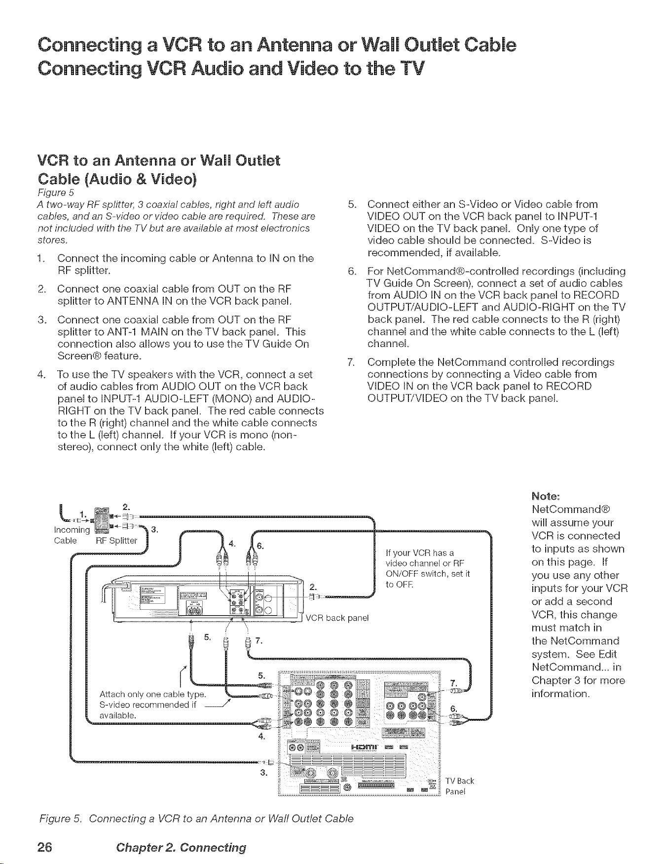
1. Connect the incoming cabb or Antenna to iN on the
2. Connect one coaxial cabb from OUT on the RF
splitter to ANTENNA iN on the VCR back panel.
3. Connect one coaxial cabb from OUT on the RF
splitter to ANT-1 MAiN on the TV back panel. This
connection also allows you to use the TV Guide On
Screen® feature.
.
To use the TV speakers with the VCR, connect a set
of audio cabbs from AUDIO OUT on the VCR back
panel to INPUT-1 AUDIO-LEFT (MONO) and AUDIO-
RIGHT on the TV back panel. The red cabb connects
to the R (right) channel and the white cable connects
to the L (left) channel. If your VCR is mono (non-
stereo), connect only the white (left) cable.
5.
6.
7.
Connect either an S-Video or Video cable from
VIDEO OUT on the VCR back panel to INPUT-1
VIDEO on the TV back panel. Only one type of
video cable should be connected. S-Video is
recommended, if available.
For NetCommand®-controlbd recordings (including
TV Guide On Screen), connect a set of audio cables
from AUDIO IN on the VCR back panel to RECORD
OUTPUT/AUDIO-LEFT and AUDIO-RIGHT on the TV
back panel. The red cable connects to the R (right)
channel and the white cable connects to the L (left)
channel.
Complete the NetCommand controlled recordings
connections by connecting a Video cable from
VIDEO IN on the VCR back panel to RECORD
OUTPUT/VIDEO on the TV back panel
Note:
NetCommand®
will assume your
VCR is connected
to inputs as shown
on this page. If
you use any other
inputs for your VCR
or add a second
VCR, this change
must match in
the NetCommand
system. See Edit
NetCommand... in
Chapter 3 for more
information.
TV Back
Figure 5. Connecting a VCR to an Antenna or Waft Outlet Cable
26 Chapter 2. Connecting
Connecting a VCR to a Cable Box (Audio & Video)
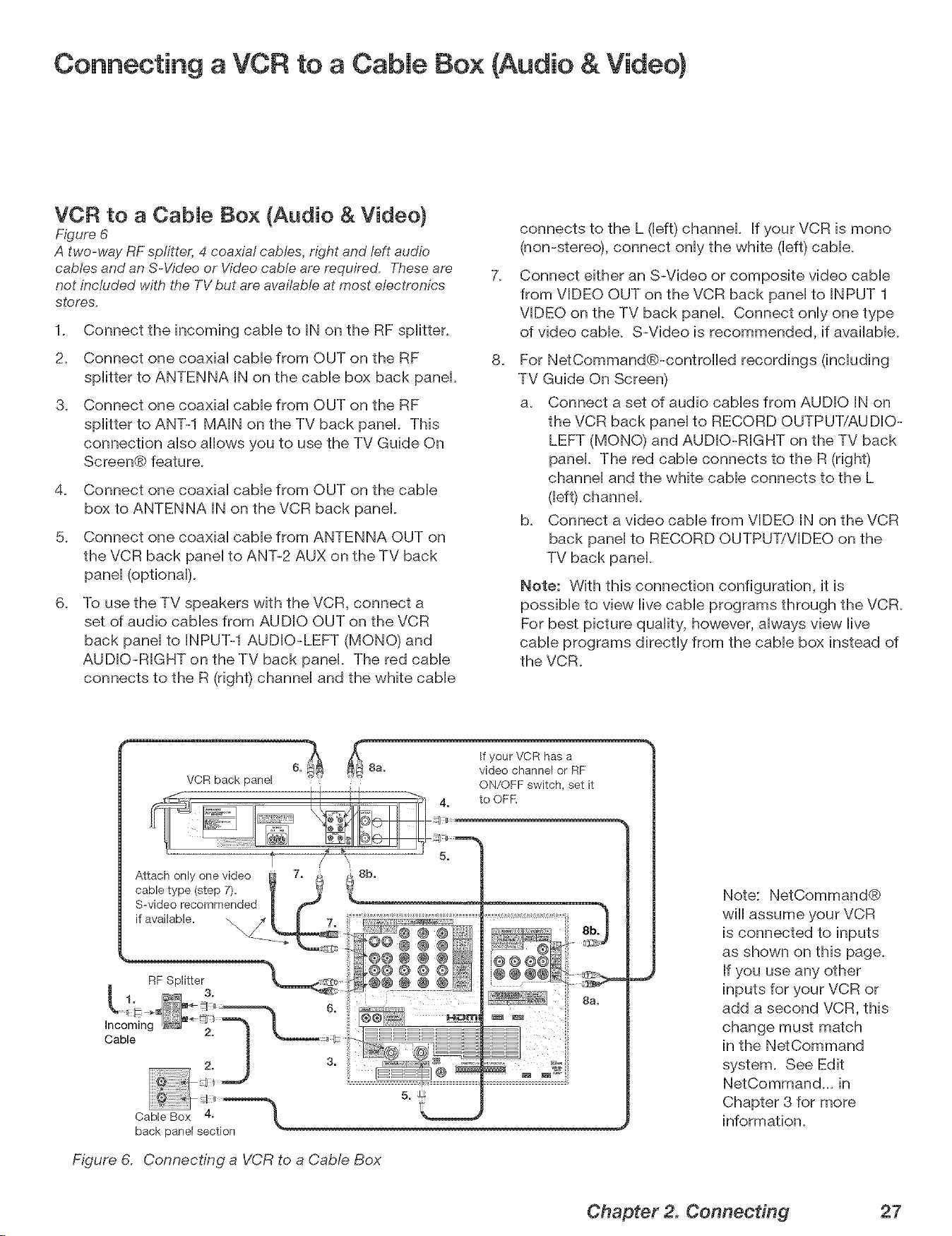
VCF{ to a CabJe Box (Audio & Video)
Figure 6
A two-way RF splitter, 4 coaxial cables, right and left audio
cables and an S-Video or Video cable are required. Theseare
not included with the TV but are avalfabteat most electronics
stores.
1. Connect the incoming cabb to IN on the RF spiitter.
2. Connect one coaxiai came from OUT on the RF
spiitter to ANTENNA IN on the came box back panel
@ Connect one coaxiai came from OUT on the RF
spiitter to ANT-1 MAiN on the TV back panel This
connection aiso allows you to use the TV Guide On
Screen® feature.
@ Connect one coaxial cable from OUT on the cable
box to ANTENNA IN on the VCR back panel
@ Connect one coaxial cable from ANTENNA OUT on
the VCR back panel to ANT-2 AUX on the TV back
panel (optional).
6_
To use the TV speakers with the VCR, connect a
set of audio cables from AUDIO OUT on the VCR
back panel to INPUT-1 AUDiO-LEFT (MONO) and
AUDIO-RiGHT on the TV back panel. The red cable
connects to the R (right) channel and the white cable
7_
8_
connects to the L (left) channel If your VCR is mono
(non-stereo), connect only the white (left) cable.
Connect either an S-Video or composite video cable
from VIDEO OUT on the VCR back panel to INPUT 1
VIDEO on the TV back panek Connect only one type
of video cable. S-Video is recommended, if available.
For NetCommand@-controiied recordings (including
TV Guide On Screen)
a. Connect a set of audio cables from AUDIO iN on
the VCR back panel to RECORD OUTPUTiAU DIO-
LEFT (MONO) and AUDIO-RiGHT on the TV back
panek The red cable connects to the R (right)
channel and the white cable connects to the L
(left) channel
@ Connect a video came from VIDEO IN on the VCR
back panel to RECORD OUTPUT/VIDEO on the
TV back panel
Note: With this connection configuration, it is
possible to view live cable programs through the VCR.
For best picture quality, however, always view live
cable programs directly from the cable box instead of
the VCR.
Attach only one video
cable type (step 7).
S-video recommended
if available. -,,,, _
Incoming
Cable
RF Splitter
3.
Cable Box 4.
back panel section
8b.
Figure 6. Connecting a VCR to a Cab@ Box
@@@@ @
@@@@ @
@@@@@
If your VCR has a
video channel or RF
ON/OFF switch, set it
to OFK
@@@@
@ @@@
Note: NetCommand@
wiii assume your VCR
is connected to inputs
as shown on this page.
If you use any other
inputs for your VCR or
add a second VCR, this
change must match
in the NetCommand
system. See Edit
NetComman@_ in
Chapter 3 for more
information.
Chapter 2. Connecting 27
Connecting an A/V Receiver (Stereo System}
Connecting a Satellite Receiver or Other Device with S -Video
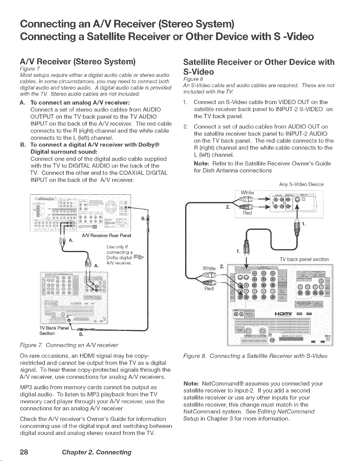
A/V Receiver (Stereo System}
Figure 7
Most setups require either a digital audio cable or stereo audio
cables. In some circumstances, you me7 need to connect both
digital audio and stereo audio. A digital audio cable is provided
with the TV. Stereo audio cables are not included.
A, To connect an analog A/V receiver:
Connect a set of stereo audio caMes from AUDIO
OUTPUT on the TV back paneHto the TV AUDIO
INPUT on the back of the A/V receiver. The red cabHe
connects to the R (right) channeH and the white cabHe
connects to the L (Heft)channel
B. To connect a digital A/V receiver with Dolby®
Digital surround sound:
Connect one end of the digitaH audio came suppHied
with the TV to DIGITAL AUDIO on the back of the
TV. Connect the other end to the COAXIAL DIGITAL
INPUT on the back of the A/V receiver.
B.I
A/V Receiver Rear Panel
Use only if
connecting a
Dolby digital
A/V receiver,
A.
Section B.
Figure 7. Connecting an A/V receiver
On rare occasions, an HDMI signal may be copy-
restricted and cannot be output from the TV as a digital
signal. To hear these copy-protected signals through the
A/V receiver, use connections for analog A/V receivers.
MP3 audio from memory cards cannot be output as
digital audio. To listen to MP3 playback from the TV
memory card player through your A/V receiver, use the
connections for an analog A/V receiver
Check the A/V receiver's Owner's Guide for information
concerning use of the digital input and switching between
digital sound and analog stereo sound from the TV.
Satellite Receiver or Other Device with
S-Video
Figure 8
An S-Video cable and audio cables are required. Theseare not
included with the T_{
.
2.
Connect an S-Video cable from VIDEO OUT on the
satellite receiver back panel to INPUT-2 S-VIDEO on
the TV back panel.
Connect a set of audio cables from AUDIO OUT on
the satellite receiver back panel to INPUT-2 AUDIO
on the TV back panel. The red cable connects to the
R (right) channel and the white cable connects to the
L (left) channek
Note: Refer to the Satellite Receiver Owner's Guide
for Dish Antenna connections
Any S-Video Device
[ White
Red
White 2,
Red
TV back panel section
@@ ®
@ @ ® @@@@
@ @ @
@@@ ,....
Figure 8, Connecting a Satelfite Receiver with S-Video
Note: NetCommand® assumes you connected your
satellite receiver to Input-2. If you add a second
satellite receiver or use any other inputs for your
satellite receiver, this change must match in the
NetCommand system. See Editing NetCommand
Setup in Chapter 3 for more information.
28 Chapter 2. Connecting
Connecting a DVD Player with Component Video
Connecting a DV[ Device
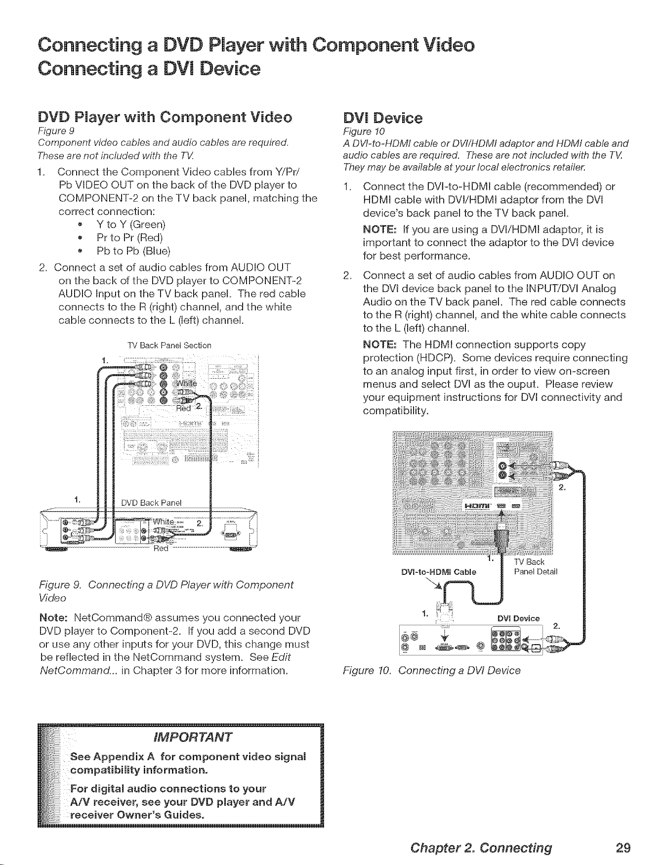
DVD Player with Component Video
Figure 9
Component video cables and audio cables are required.
Theseare not included with the TV.
1. Connect the Component Video cables from Y/Pri
Pb VIDEO OUT on the back of the DVD player to
COMPONENT-2 on the TV back panel, matching the
correct connection:
Y to Y (Green)
PFto PF (Red)
Pb to Pb (Blue)
2. Connect a set of audio cables from AUDIO OUT
on the back of the DVD player to COMPONENT-2
AUDIO Input on the TV back panel. The red cable
connects to the R (right) channel, and the white
cable connects to the L (left) channel.
TV Back Panel Section
DV[ Device
Figure 10
A DW-to-HDMI cable or DVI/HDMI adaptor and HDMt cable and
audio cables are required. These are not included with the T_Z
Theymay be available at your local electronics retailer.
,
2.
Connect the DVI-to-HDMt cable (recommended) or
HDMI cable with DVt/HDMI adaptor from the DVl
device's back panel to the TV back panel.
NOTE: If you are using a DVl/HDM[ adaptor, it is
important to connect the adaptor to the DVt device
for best performance.
Connect a set of audio cables from AUDIO OUT on
the DVl device back panel to the INPUT!DVl Analog
Audio on the TV back panel. The red cable connects
to the R (right) channel, and the white cable connects
to the L (left) channel.
NOTE: The HDM[ connection supports copy
protection (HDCP). Some devices require connecting
to an analog input first, in order to view on-screen
menus and select DVl as the ouput. Please review
your equipment instructions for DVl connectivity and
Figure 9. Connecting a DVD Player with Component
Video
Note: NetCommand® assumes you connected your
DVD player to Component-2. If you add a second DVD
or use any other inputs for your DVD, this change must
be reflected in the NetCommand system. See Edit
NetCommand... in Chapter 3 for more information.
DV[=to=HDMI Cable
1,
DV[ Device
r
Figure 10. Connecting a DW Device
Chapter 2. Connecting 29
Connecting an HOTV Cable Box or Satellite Receiver with
Component Video
Connecting an HOMI Device
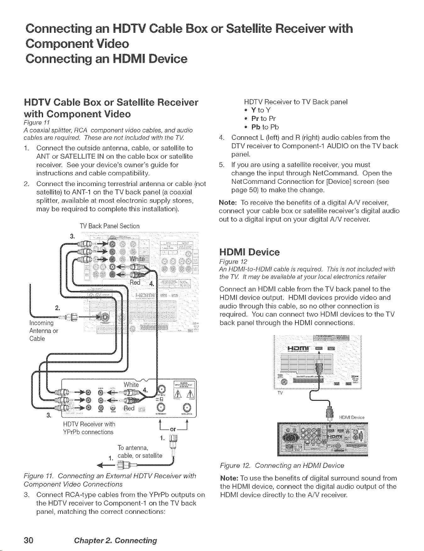
HOTV CabJe Box or Satellite Receiver
with Component Video
Figure 11
A coaxial spfitter, RCA component w'deocables, and audio
cables are required. These are not included with the TV.
1. Connect the outside antenna, cabb, or satellite to
ANT or SATELLITE IN on the came box or satellite
receiver. See your device's owner's guide for
instructions and came compatibility.
2. Connect the incoming terrestrial antenna or cable (not
satellite) to ANT-1 on the TV back panel (a coaxial
splitter, available at most electronic supply stores,
may be required to complete this installation).
TV Back Panel Section
hcoming
Antenna or
Cable
2
Red £,
HDTVReceiverwith t =_
YPrPbconnections or
1.
To antenna,
Figure 11. Connecting an External HDTV Receiver with
Component Video Connections
3. Connect RCA-type cables from the YPrPb outputs on
the HDTV receiver to Component-1 on the TV back
panel, matching the correct connections:
4_
5_
HDTV Receiver to TV Back panel
YtoY
Pr to Pr
Pb to Pb
Connect L (left) and R (right) audio cables from the
DTV receiver to Component-1 AUDIO on the TV back
panel.
If you are using a satellite receiver, you must
change the input through NetCommand. Open the
NetCommand Connection for [Device] screen (see
page 50) to make the change.
Note: To receive the benefits of a digital AiV receiver,
connect your cable box or satellite receiver's digital audio
out to a digital input on your digital AiV receiver.
HOMI Device
Figure 12
An HDMI-to-HDMI cable is required. This is not included with
the TV. It may be available at your local electronics retailer
Connect an HDMI cable from the TV back panel to the
HDMI device output. HDMI devices provide video and
audio through this cable, so no other connection is
required. You can connect two HDMI devices to the TV
back panel through the HDMI connections.
Figure 12. Connecting an HDMI Device
Note: To use the benefits of digital surround sound from
the HDMI device, connect the digital audio output of the
HDMI device directly to the A/V receiver.
30 Ohapter 2. ComTecting
Connecting a Computer with an HDIVll or DVl Monitor Output
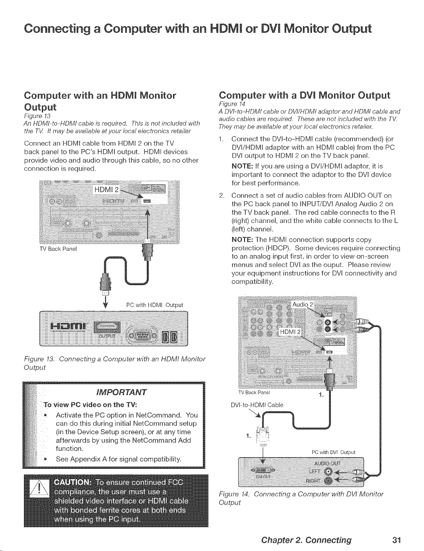
Computer with an HDMI Monitor
Figure 13
An HDMI-to-HDM/ cable is required. This is not included with
the TV. It may be available at your local electronics retailer
Connect an HDMI cable from HDMI 2 on the TV
back panel to the PC's HDMI outpuL HDMI devices
provide video and audio through this cable, so no other
connection is required.
TV Back Panel
PC with HDMI Output
Computer with a DVl Monitor Output
Figure 14
A DVl-to-HDMI cable or DVI/HDMI adaptor and HDMI cable and
audio cables are required. These are not included with the TV.
Theymay be available at your local electronics retailer.
2_
Connect the DVI-to-HDMI cable (recommended) (or
DVl/HDMI adaptor with an HDMI cable) from the PC
DVI output to HDMI 2 on the TV back panel.
NOTE: If you are using a DVI/HDMI adaptor, it is
important to connect the adaptor to the DVI device
for best performance.
Connect a set of audio cables from AUDIO OUT on
the PC back panel to INPUTiDVl Analog Audio 2 on
the TV back panel. The red cable connects to the R
(right) channel, and the white cable connects to the L
(left) channel.
NOTE: The HDMI connection supports copy
protection (HDCP). Some devices require connecting
to an analog input first, in order to view on-screen
menus and select DVl as the ouput. Please review
your equipment instructions for DVl connectivity and
compatibility.
Figure 13. Connecting a Computer with an HDM/ Monitor
Output
IMPORTANT
To view PC video on the TV:
Activate the PC option in NetCommand. You
can do this during initial NetCommand setup
(in the Device Setup screen), or at any time
afterwards by using the NetCommand Add
function.
See Appendix A for signal compatibility.
TV Back Panel
DVl-to=HDMI Cable
PC with DW Output
Figure 14. Connecting a Computer with DW Monitor
Output
Chapter 2. Connecting 31
Connecting the [R Emitter NetCommand ®
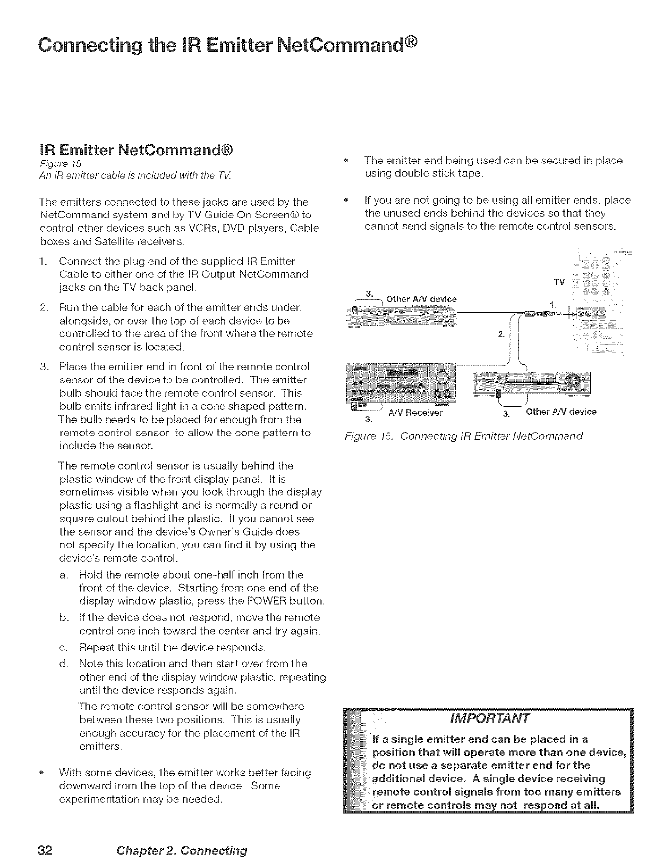
[R Emitter NetCommand®
Figure 15
An IR emitter cable is included with the TV.
The emitters connected to these jacks are used by the
NetCommand system and by TV Guide On ScreenCb to
control other devices such as VCRs, DVD players, Cable
boxes and Satellite receivers.
1_ Connect the plug end of the supplied [R Emitter
CaMe to either one of the [R Output NetCommand
jacks on the TV back panel
2_
Run the came for each of the emitter ends under,
alongside, or over the top of each device to be
controlled to the area of the front where the remote
control sensor is [ocated.
3_ Place the emitter end in front of the remote control
sensor of the device to be contro[[ed. The emitter
bulb should face the remote control sensor. This
bulb emits infrared light in a cone shaped pattern.
The bulb needs to be placed far enough from the
remote control sensor to allow the cone pattern to
include the sensor.
The remote control sensor is usually behind the
plastic window of the front display panel It is
sometimes visible when you look through the display
plastic using a flashlight and is normally a round or
square cutout behind the plastic. If you cannot see
the sensor and the device's Owner's Guide does
not specify the location, you can find it by using the
device's remote control
a. Hold the remote about one-haft inch from the
front of the device. Starting from one end of the
display window plastic, press the POWER button.
b. If the device does not respond, move the remote
control one inch toward the center and try again.
c. Repeat this until the device responds.
d. Note this location and then start over from the
other end of the display window plastic, repeating
until the device responds again.
The remote control sensor wi[[ be somewhere
between these two positions. This is usually
enough accuracy for the placement of the [R
emitters.
With some devices, the emitter works better facing
downward from the top of the device. Some
experimentation may be needed.
The emitter end being used can be secured in place
using double stick tape.
If you are not going to be using a[[ emitter ends, place
the unused ends behind the devices so that they
cannot send signals to the remote control sensors.
Other A/V device
TV
A/V Receiver 3. Other A/V device
3.
Figure 15, Connecting IR Emitter NetCommand
IMPORTANT
single emitter end can be placed in a
position that will operate more than one device,
do not use a separate emitter end for the
additional device. A single device receiving
! remote control signals from too many emitters
remote controls not res _ond at all,
32 Chapter 2. Connecting
Connecting Compatibme IEEE 1394 Devices
CompatibJe IEEE 1394 Devices
Compatible A/V devices include some, but not all, came
boxes, D-VHS VCRs, A/V discs, and future products. It
is aHsopossibHe to connect devices to the TV that have
[EEE 1394 connectors but are not compatibHe with the
TV or with the NetCommand® controH system. Areas of
compatibiHity to consider are:
1. Digital Video Signals
The TV is aMe to decode MPEG2 and DV video as
provided by some camcorders. If the TV is unaMe to
decode the digitaH signaH suppHied by your camcorder, try
S-video with anaHog audio connections instead. Other
types of digitaHvideo, such as PC video provided by
some computers, must be decoded by the source device
and sent to the TV as anaHog video, S-video, or HDMI
video.
2. Digital Audio Signals
When received with video signals, the TV is able to
decode Dolby Digital signals and MPEG audio signals.
Other types of digital audio as provided by some digital
recording devices, such as MP3 audio and DTS audio,
cannot be decoded by the TV when received over IEEE
1394
The TV may not be able to pass incompatible digital audio
signals on the coaxial digital audio output, however, these
signals may pass on the EEE 1394 cable to other devices.
3. Digital Control Signal
The TV can serve as the control center for IEEE 1394
audio/video devices, such as VCRs, A/V Discs, tuners,
cable boxes and amplifiers that are compatible with the
following IEEE 1394 control standards.
EIA=775 is designed for tuning devices such as cable
boxes, allowing the device to send simple graphics.
This standard does not, however, allow the TV to
control the cable box by IEEE 1394.
AV/C {Audio Video Control) is designed to provide
basic controls such as play, stop, channel selection,
and volume, as appropriate for the device.
The IEEE 1394 interface may not provide reliable control
signals for some DV camcorders, especially older models.
If your camcorder operates incorrectly or not at all, use
the camcorder's control buttons instead of the IEEE 1394
connection.
Some devices may be a combination of two or more
types of devices. For example, there may be a recording
device that is also a tuning device. Each portion of the
device is called a sub-unit. When you select a device on
the Device Selection menu that has sub-units, a pop-
up menu will appear so you can select which sub-unit
section you wish to use.
When Connecting IEEE 1394 Devices
Do not loop the last device in the chain back to the
TV. When the device chain is looped, the TV may not
be able to work with the other devices.
Digital
TV
Place devices that have only a mechanical (two-
position) power switch at the end of the chain or
leave the power switch in the On position. When
turned Off, IEEE 1394 signals may not be able to
pass through the device to other devices.
Place devices with the slowest communication
speed at the end of the chain. Sometimes the
communication speed will be marked near the IEEE
1394 connector with an "S" number. The higher the
number, the faster the communication speed. This
TV has a communication speed of $400. Devices
with slow communication speed can interfere with
IEEE 1394 signals from faster devices. When using
NetCommand to set up a digital recording between
a faster device and a slower device, make the slower
device the source and make the faster device the
recorder_
Do not use an IEEE 1394 cable over 15 feet in length
between each device.
This TV is an IEEE 1394a device. It can be used
with a 1394b system when an EEE-1394a-to-1394b
convertor is used. 1394b systems are capable of
greater distances and multi-room applications.
IMPORTANT
Playback
, When viewing DV camcorders, it is normal
for temporary audio and video distortion to
occur under conditions such as:
i!i
Playback start and stop
® Playback pause
* Forward or reverse picture search
Some DV Camcorder models are not
patible with this TV's IEEE 1394 system,
Because of this, the "New 1394 Device"
screen will not appear when the camcorder
ia connected, For playback of incompatible
DV camcorders, try S-video with analog
audio connections instead,
Chapter 2. Connecting 33
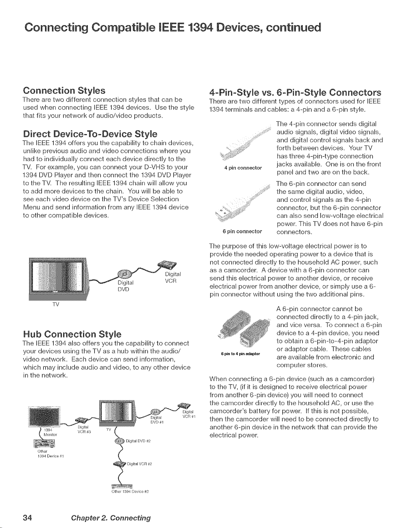
Connecting Compatible IEEE 1394 Devices, continued
Connection StyJes
There are two different connection sues that can be
used when connecting IEEE 1394 devices. Use the sue
that fits your network of audio/video products.
Direct DeviceoTooDevice StyJe
The BEEE1394 offers you the capabiiity to chain devices,
uniike previous audio and video connections where you
had to individuaUy connect each device directly to the
TV. For exampb, you can connect your D-VHS to your
1394 DVD Hayer and then connect the 1394 DVD Piayer
to the TM The resuiflng IEEE 1394 chain wiU allow you
to add more devices to the chain. You will be able to
see each video device on the TV's Device Selection
Menu and send information from any IEEE 1394 device
to other compatible devices.
TV
Digital
Digital VCR
DVD
Hub Connection StyJe
The EEE 1394 also offers you the capability to connect
your devices using the TV as a hub within the audio/
video network. Each device can send information,
which may include audio and video, to any other device
in the network.
DVD #1
Digital TV
1394 VCR #3
Monitor
) Digital DVD #2
Other
1394 Deqce #1
Digital VCR #2
Digital
VCR #1
4-PinoStyme vs. 6oPin-Styme Connectors
There are two different types of connectors used for IEEE
1394 terminals and cables: a 4-pin and a 6-pin style.
4 pin connector
6 pin connector
The 4-pin connector sends digital
audio signals, digital video signals,
and digital control signals back and
forth between devices. Your TV
has three 4-pin-type connection
jacks available. One is on the front
panel and two are on the back.
The 6-pin connector can send
the same digital audio, video,
and control signals as the 4-pin
connector, but the 6-pin connector
can also send low-voltage electrical
power. This TV does not have 6-pin
connectors.
The purpose of this low-voltage electrical power is to
provide the needed operating power to a device that is
not connected directly to the household AC power, such
as a camcorder. A device with a 6-pin connector can
send this electrical power to another device, or receive
electrical power from another device, or simply use a 6-
pin connector without using the two additional pins.
6 pin to 4 pin adaptor
A 6-pin connector cannot be
connected directly to a 4-pin jack,
and vice versa. To connect a 6-pin
device to a 4-pin device, you need
to obtain a 6-pin-to-4-pin adaptor
or adaptor cable. These cables
are available from electronic and
computer stores.
When connecting a 6-pin device (such as a camcorder)
to the TV, (if it is designed to receive electrical power
from another 6-pin device) you wiii need to connect
the camcorder directly to the household AC, or use the
camcordeFs battery for power. If this is not possible,
then the camcorder will need to be connected directly to
another 6-pin device in the network that can provide the
electrical power.
Other 1394 Device #2
34 Chapter 2. Connecting
Helpful Hints for NetCommand Connections
e.
A_
Q.
A_
My VCR (or other device} does not have two sets of stereo audio outputs. How can I connect this device's
audio to both the TV and the A/V Receiver?
Connect the single set of stereo audio outputs to the TV onHy. Use Edit NetCommand® to change the setup of this
device. In the Connection screen of "Change" make sure both audio and video for the TV input are check marked
and the audio for the AVR input is not check marked. This will allow the NetCommand system to use the TV
outputs to transfer the device's audio to the AiV Receiver. See Edit NetCommand in the next chapter for details.
I have both the TV stereo audio output and TV digital audio output connected to the same input
designations on my A/V Receiver, How do I switch between analog audio and digital audio?
In most setups, analog audio is also output as digital audio, so no switching is required, and there is no need to
connect the analog output. In some circumstances, however, you may also need analog audio from the TV. For
example, MP3 audio is only output in analog format, so you must connect the TV's analog AUDIO OUTPUT to the
AiV Receiver if you want to hear MP3 audio through the AiV receiver. Refer to your AiV Receiver user's guide to
find out how analog/digital audio switching works.
If your AiV Receiver's remote control has an Analog/Digital Audio key, you can use the GUIDE key with the
following models to control switching:
Mitsubishi M-VR900 Integra DTR-9J
Denon AVR-2700 Kenwood VR-2080
To make the switch, press the Device key on the TV's remote control, and from the Device Selection menu,
press the Audio key. Then, with the AiV Receiver highlighted, press the GUIDE key to make the switch.
If you have some other AiV Receiver model, use the TV's learn function to learn the analog/digital audio
code for the GUIDE key. Follow the instructions above for using the GUIDE key.
If your AiV Receiver has an Analog/Digital selection key on the front panel only, and not on the remote,
then your only option is to use that key to perform switching.
Q. The front panel of my A/V Receiver is too tall or too convex for the IR emitter signal to reach the remote
control sensor of the A/V Receiver. What can I do?
A. There are several possible solutions.
1_ Mount the IR Emitter on the top, front edge of the AiV Receiver over the remote control sensor. Use tape to
secure it in place.
2_ Mount the IR Emitter on the underside of the shelf above the AiV Receiver (if the AiV Receiver is in a cabinet).
Use double sided tape to secure it in place.
3_ Some small stick-on emitters from other manufacturers may be compatible with this TV's IR Emitter jacks.
These may be used instead of the supplied IR Emitters.
Q. I occasionally need to see the menu from my A/V Receiver. How can I connect it to the TV for this purpose?
A. You can connect the video output of the A/V Receiver to an unused input on the TV. Then use Edit NetCommand
to "Add" this as an "Other" device, not an AiV Receiver. On the "Connection" screen, indicate which TV input was
used and check mark the video box. Make sure the TV input audio box and both the audio and video boxes for
the AVR input are not check marked. You should also name this device so you can easily identify it on the Device
Selection Menu. You can also use Input 3 on the front panel.
Q.
A_
I have a high definition receiver I would like to connect and it also has an S=video output I would like to be
able use as well. is there any way to connect this receiver both ways?
Yes, this item will appear twice in the Device Selection Menu. Just add this unit once using the Component-1 and
once using one of the S-video inputs. Make sure you indicate that this is the same manufacturer for both. We
suggest that you connect stereo audio outputs with the S-video to the TV so that you do not need to use two inputs
on the AiV Receiver. If this is a NetCommand compatible HDTV receiver and HD or SD outputs can be switched by
remote control, see Edit NetCommand in the next chapter for NetCommand control of this feature.
Chapter 2. Connecting 35

mm8
NetCommand® Introduction ........................... 38
Using the Remote ControU with NetCemmand® ............. 39
NetCommand® Setup On-Screen Buttons .................. 40
3D GraphicaU _VJSWP0Jn[® Menu System ..................... 41
NetCommand® lnitiaU Setup ........................... 42
Edit NetCommand®: Add an A/V Receiver ................. 45
Edit NetCommand®: Add Devices ....................... 48
Edit NetCommand®: Change or DeUete Devices ............. 52
IEEE 1394 Devices and NetCommand® ControU .............. 53
Adding IEEE 1394 Devices Automatically ................... 54
NetCommand® Introduction
NetCommand makes your TV the heart of your Home Theater
NetCommand@ is an intelligent control system that makes your Mitsubishi TV the heart of your home theater. With
NetCommand, the TV sends signals to the other devices in the system via the IR emitters, telling the devices to play,
record, change inputs, adjust volume, change channels and many more functions. All of this is accomplished with one
remote control and without changing control layers.
IR Learning and IEEE 1394 Support
The (R "Learning" feature of NetCommand allows the TV to barn the
remote control signals for new devices that the TV is not preprogrammed
to operate. NetCommand@ also includes the capability of controlling
IEEE 1394 devices by sending control signals on a FireWire@ cable.
V®
Using HetOommand is completely optional
When you first turn on the TV, the NetCommand Setup Wizard launches. If you decide to use NetCommand, follow
the on-screen instructions. If you choose not to use it right away, simply quit the Setup Wizard and NetCommand will
remain inactive. Later, if you decide to use NetCommand, you can easily access the Setup Wizard.
HetOommand and Levels of Control
When you set up NetCommand, you decide how much control you want the TV to have over your home theater system.
You have the choice of performing a basic, limited, or complete NetCommand setup.
o Basic Setup
In a basic setup, NetCommand will:
0 automatically switch to the correct TV input when you want to view programming from a different device. All
you do is select the device from the on-screen device selection menu. This saves you from having to search for
the correct input every time you want to change devices. Unused inputs are automatically deactivated so that
you don't see them in the menu.
0 show an on-screen icon for each device connected to the TV so you always know what devices are available.
Note that with a basic setup, you still need to use the remote control specific to each device.
Limited Setup
In a limited setup, you get the benefits of the basic setup plus NetCommand control over the specific devices you
have chosen. Use this type of setup if you:
0 only want NetCommand to control a few devices, such as the TV, a playback device (like a DVD player), and a
cable box. With this setup, you can use the TV's remote to control these devices.
0 want to use TV Guide On Screen@ to control your cable box and VCR and/or AiV disc. After performing this
setup, you can use the TV's remote to control these devices.
Full Setup
Perform a full setup if you want NetCommand to:
0 control a surround sound AiV receiver.
0 automatically change input selections for the AiV receiver.
0 control all devices with the TV's remote, including the AiV receiver.
HetOommand Helps You Manage Your Home Theater
With the NetCommand Review screen you can:
view a summary of all devices connected to the TV and the input used for each device.
deactivate or turn off unused input connections; reactivate or turn them on.
If you need to change your setup, the NetCommand sub-menu lets you easily
add new devices.
deleted devices you have disconnected.
change device and input selections.
38 Chapter 3. NetCommand Setup and Editing
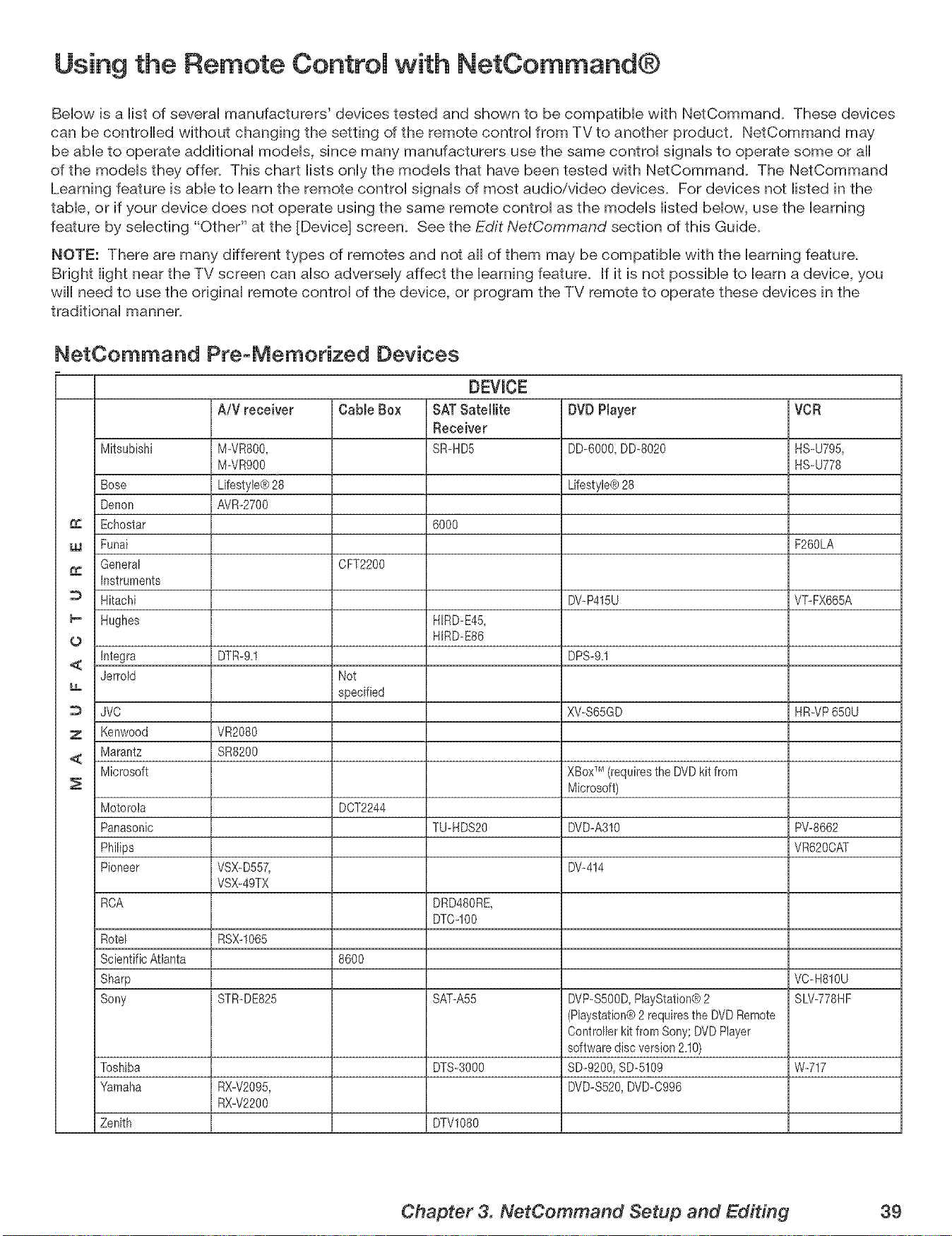
Using the Remote Control with NetCommand®
Bellow is a Histof severaH manufacturers' devices tested and shown to be compatibHe with NetCommand. These devices
can be controlled without changing the setting of the remote controH from TV to another product. NetCommand may
be aMe to operate additionaH modeHs, since many manufacturers use the same controH signaHs to operate some or aH
of the modeHs they offer. This chart HistsonHythe modeHs that have been tested with NetCommand. The NetCommand
Learning feature is abHeto Hearnthe remote controH signaHs of most audio/video devices. For devices not Histed in the
tame, or if your device does not operate using the same remote controH as the modeHs Histed bellow, use the learning
feature by selecting "Other" at the [Device] screen. See the Edit NetCommand section of this Guide.
NOTE: There are many different types of remotes and not all of them may be compatible with the learning feature.
Bright light near the TV screen can also adversely affect the learning feature. If it is not possible to learn a device, you
will need to use the original remote control of the device, or program the TV remote to operate these devices in the
traditional manner.
NetCommand PreoMemorized Devices
DEVICE
AiV receiver Cable Box SATSatellite DVDPlayer VCR
Receiver
Mitsubishi M-VR800, SR_HD5 DD-6000, DD-8020 HS_U795,
M-VR900 HS_U778
Bose Lifestyle® 28 Lifestyle® 28
Denon AVR_2700
Echostar 6000
w Funai F260LA
General CFT2200
Instruments
Hitachi DV-P415U VT-FX665A
I_ Hughes HIRD_E45,
0 HIRD_E86
<_ Integra DTR-9,1 DPS-9,1
Jerrold Not
specified
JVO XWS65GD HR_VP650U
7 Kenwood VR2080
Marantz SR8200
<
Microsoft XBoxTM(requires the DVD kit from
Microsoft)
Motorola DCT2244
Panasonic TU_HDS20 DVD-A310 PW8662
Philips VR620CAT
Pioneer VSX-D557, DW414
VSX-49TX
RCA DRD480RE,
DTC-IO0
Rotel RSX-1065
Scientific Atlanta 8600
Sharp VO-H810U
Sony STR-DE825 SAT-A55 DVP-S5OOD,PlayStation® 2 SLV-778HF
(Playstation® 2 requires the DVD Remote
Controller kit from Sony; DVD Player
software disc version 2,10)
Toshiba DTS-3000 SD-9200, SD-5109 W-717
Yamaha RX-V2095, DVD-S520, DVD-0996
RX-V2200
Zenith DTVl080
Chapter 3. NetCommand Setup and Editing 39
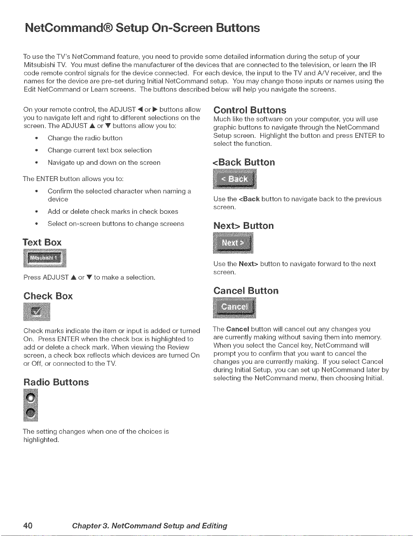
NetCommand® Setup On-Screen Buttons
To use the TV's NetCommand feature, you need to provide some detailed information during the setup of your
Mitsubishi TV. You must define the manufacturer of the devices that are connected to the television, or learn the IR
code remote control signals for the device connected. For each device, the input to the TV and AiV receiver, and the
names for the device are pre-set during Initial NetCommand setup. You may change those inputs or names using the
Edit NetCommand or Learn screens. The buttons described below wiii help you navigate the screens.
On your remote control, the ADJUST "_ or 1_buttons aiiow
you to navigate left and right to different selections on the
screen. The ADJUST ,A or T buttons allow you to:
Change the radio button
Change current text box selection
o Navigate up and down on the screen
The ENTER button allows you to:
o Confirm the selected character when naming a
device
Add or delete check marks in check boxes
o Select on-screen buttons to change screens
Text Box
ControJ Buttons
Much iike the software on your computer, you wiii use
graphic buttons to navigate through the NetCommand
Setup screen. Highlight the button and press ENTER to
select the function.
<Back Button
Use the <Back button to navigate back to the previous
screen.
Next> Button
Press ADJUST A or W to make a selection.
Check Box
Use the Next> button to navigate forward to the next
screen.
CanceJ Button
Check marks indicate the item or input is added or turned
On. Press ENTER when the check box is highlighted to
add or delete a check mark. When viewing the Review
screen, a check box reflects which devices are turned On
or Off, or connected to the TM
Radio Buttons
The Cancel button wiii cancel out any changes you
are currently making without saving them into memory.
When you select the Cancel key, NetCommand will
prompt you to confirm that you want to cancel the
changes you are currently making. If you select Cancel
during hitial Setup, you can set up NetCommand later by
selecting the NetCommand menu, then choosing Initial.
The setting changes when one of the choices is
40 Chapter 3. NetCommand Setup and Editing
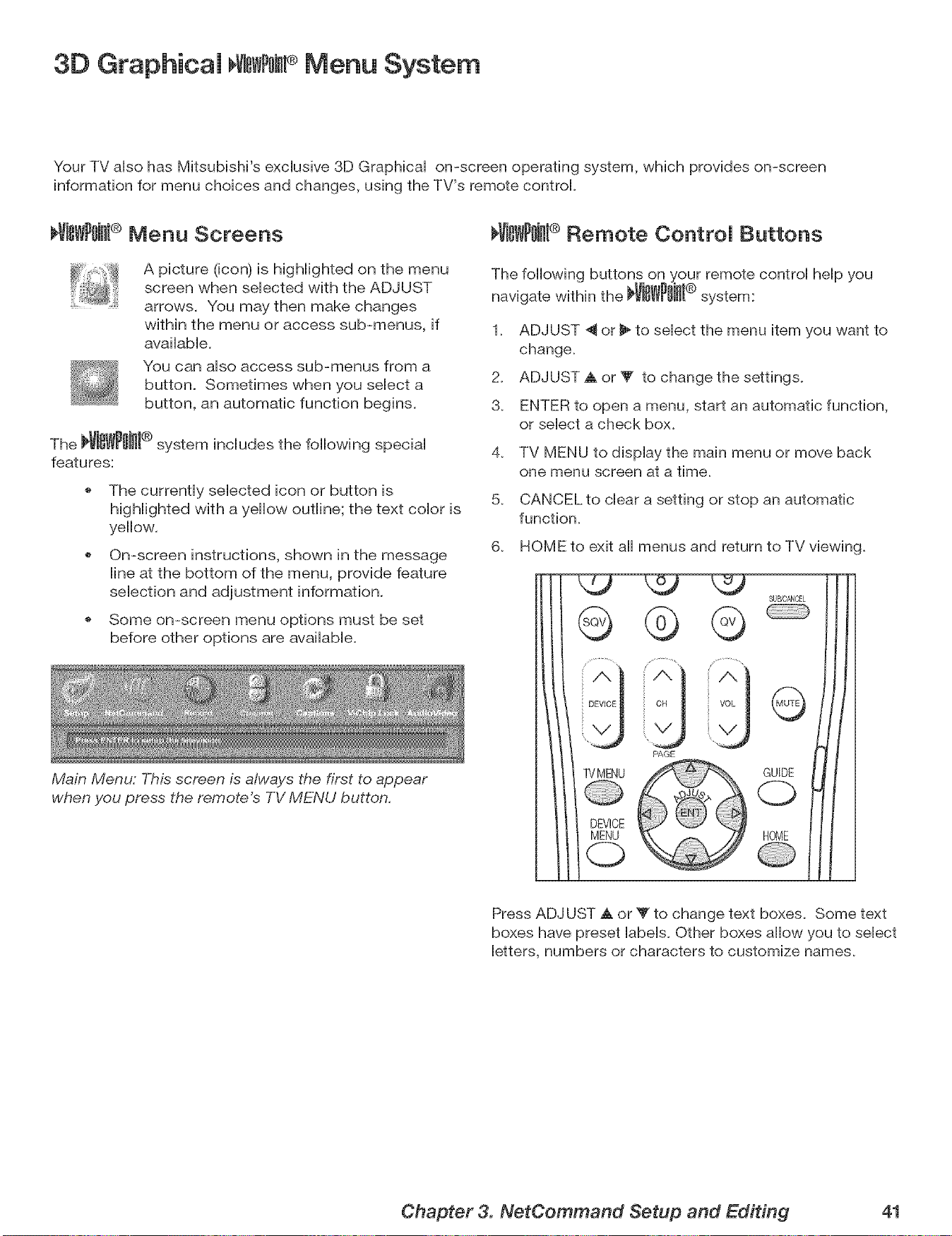
3D Graphicam VNs #omPMenu System
Your TV aiso has Mitsubishi's exciusive 3D Graphbai on-screen operating system, which provides on-screen
information for menu choices and changes, using the TV's remote control
I_VISWP0iJll® Menu Screens
A picture (icon) is highiighted on the menu
screen when seiected with the ADJUST
arrows. You may then make changes
within the menu or access sub-menus, if
avaiiabie.
You can aiso access sub-menus from a
button. Sometimes when you seiect a
button, an automatic function begins.
The _i_i_l ® system includes the following special
features:
The currently selected icon or button is
highlighted with a yellow outline; the text color is
yellow.
On-screen instructions, shown in the message
line at the bottom of the menu, provide feature
selection and adjustment information.
Some on-screen menu options must be set
before other options are available.
Main Menu: This screen is always the first to appear
when you press the remote's TV MENU button.
_ViSWPOJHI® Remote Control Buttons
The following buttons on your remote control help you
navigate within the _Vi_WPWI® system:
1. ADJUST _ or _" to select the menu item you want to
change.
2. ADJUST A or T to change the settings.
3. ENTER to open a menu, start an automatic function,
or select a check box.
4. TV MENU to display the main menu or move back
one menu screen at a time.
5. CANCEL to clear a setting or stop an automatic
function.
6. HOME to exit all menus and return to TV viewing.
G
DEVICE
TVMENU
(2)
PAGE
G
GUIDE
C)
HOME
Press ADJUST a. or _' to change text boxes. Some text
boxes have preset labels. Other boxes allow you to select
letters, numbers or characters to customize names.
Chapter 3. NetCommand Setup and Editing 41
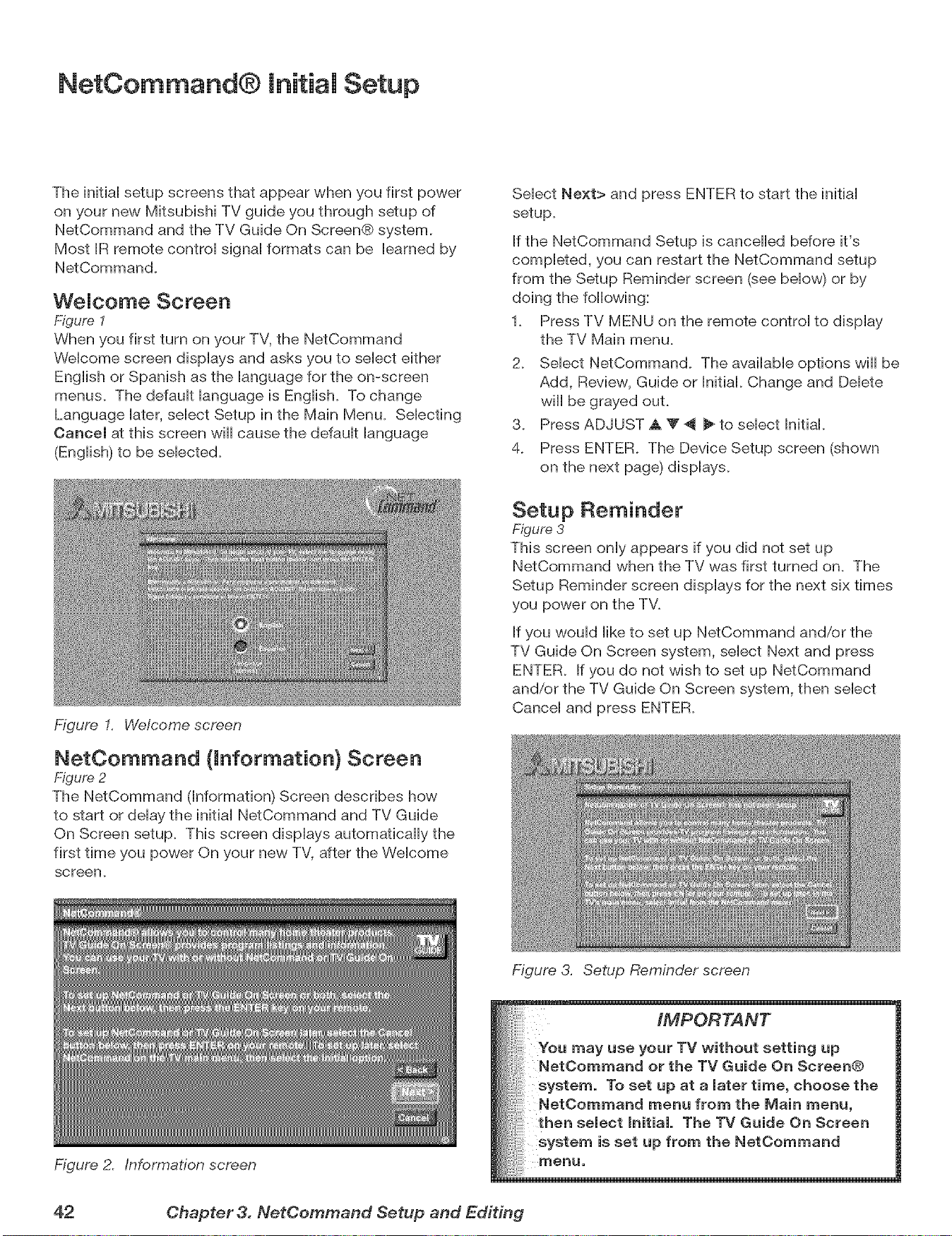
NetCommand® initial Setup
The initiaHsetup screens that appear when you first power
on your new Mitsubishi TV guide you through setup of
NetCommand and the TV Guide On Screen@ system.
Most JRremote controH signaHformats can be Hearned by
NetCommand.
WeJcome Screen
Figure 1
When you first turn on your TV, the NetCommand
WeHcome screen dispHays and asks you to seHect either
EngHishor Spanish as the Hanguage for the on-screen
menus. The defauHt Hanguage is EngHish. To change
Language Hater,seHect Setup in the Main Menu. SeHecting
Cancel at this screen will cause the defauHt Hanguage
(EngHish)to be seHected.
Figure I. Welcome screen
NetOommand (information} Screen
Figure 2
The NetCommand (information) Screen describes how
to start or delay the initial NetCommand and TV Guide
On Screen setup. This screen displays automatically the
first time you power On your new TV, after the Welcome
screen.
Figure 2. Information screen
Select Next> and press ENTER to start the initial
setup.
If the NetCommand Setup is cancelled before it's
completed, you can restart the NetCommand setup
from the Setup Reminder screen (see below) or by
doing the following:
1. Press TV MENU on the remote control to display
the TV Main menu.
2. Select NetCommand. The available options will be
Add, Review, Guide or Initial. Change and Delete
will be grayed out.
3. Press ADJUST A T _ _ to select initial.
4. Press ENTER. The Device Setup screen (shown
on the next page) displays.
Setup Reminder
Figure 3
This screen only appears if you did not set up
NetCommand when the TV was first turned on. The
Setup Reminder screen displays for the next six times
you power on the TV.
If you would like to set up NetCommand and/or the
TV Guide On Screen system, select Next and press
ENTER. If you do not wish to set up NetCommand
and/or the TV Guide On Screen system, then select
Cancel and press ENTER.
Figure 3. Setup Reminder screen
IMPORTANT
You use your TV without setting up
or the TV Guide On Screen@
system. To set up at a Jater time, choose the
NetOommand menu from the Main menu,
then seJect hitiaL The TV Guide On Screen
system is set up from the NetCommand
menu,
42 Chapter 3. NetCemmand Setup and Editing
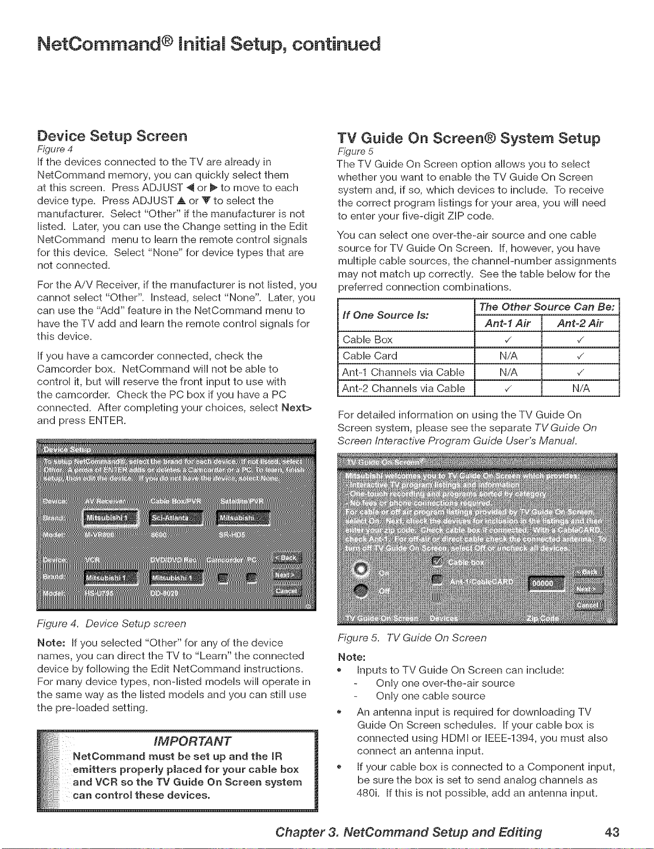
NetCommand ® Initial Setup, continued
Device Setup Screen
Figure 4
If the devices connected to the TV are akeady in
NetCommand memory, you can qubHy sebct them
at this screen. Press ADJUST 4 or _ to move to each
device type. Press ADJUST A or V to sebct the
manufacturer. Sebct "Other" if the manufacturer is not
iisted. Later, you can use the Change setting in the Edit
NetCommand menu to barn the remote controi signais
for this device. Sebct "None" for device types that are
not connected.
For the A/V Receiver, if the manufacturer is not iisted, you
cannot sebct "Other". Instead, sebct "None". Later, you
can use the "Add" feature in the NetCommand menu to
have the TV add and barn the remote controi signab for
this device.
If you have a camcorder connected, check the
Camcorder box. NetCommand will not be abb to
controi it, but will reserve the front input to use with
the camcorder. Check the PC box if you have a PC
connected. After completing your choices, select Next>
and press ENTER.
TV Guide On Screen® System Setup
Figure 5
The TV Guide On Screen option allows you to select
whether you want to enable the TV Guide On Screen
system and, if so, which devices to include. To receive
the correct program listings for your area, you will need
to enter your five-digit ZIP code.
You can select one over-the-air source and one cable
source for TV Guide On Screen. If, however, you have
multiple cable sources, the channePnumber assignments
may not match up correctly. See the table below for the
_referred connection combinations.
If One Source Is:
Cable Box
Cable Card
Ant-1 Channels via Cable
Ant-2 Channels via Cable
The Other Source Can Be:
Ant-1 Air
N/A
NiA
Ant=2 Air
,/
v_
N/A
For detailed information on using the TV Guide On
Screen system, please see the separate TV Guide On
Screen interactive Program Guide User's Manual
Figure 4. Device Setup screen
Note: If you selected "Other" for any of the device
names, you can direct the TV to "Learn" the connected
device by following the Edit NetCommand instructions.
For many device types, non-listed models will operate in
the same way as the listed models and you can still use
the preqoaded setting.
IMPORTANT
NetCommandmustbesetupandthe IR
emitters properly placed for your cable box
:, and VCR so the TV Guide On Screen system
can control these devices.
Figure 5. TV Guide On Screen
Note:
Inputs to TV Guide On Screen can include:
Only one over-the-air source
Only one cable source
An antenna input is required for downloading TV
Guide On Screen schedules. If your cable box is
connected using HDMI or EEE-1394, you must also
connect an antenna input.
If your cable box is connected to a Component input,
be sure the box is set to send analog channels as
480i. If this is not possible, add an antenna input.
Chapter 3. NetCommand Setup and Editing 43
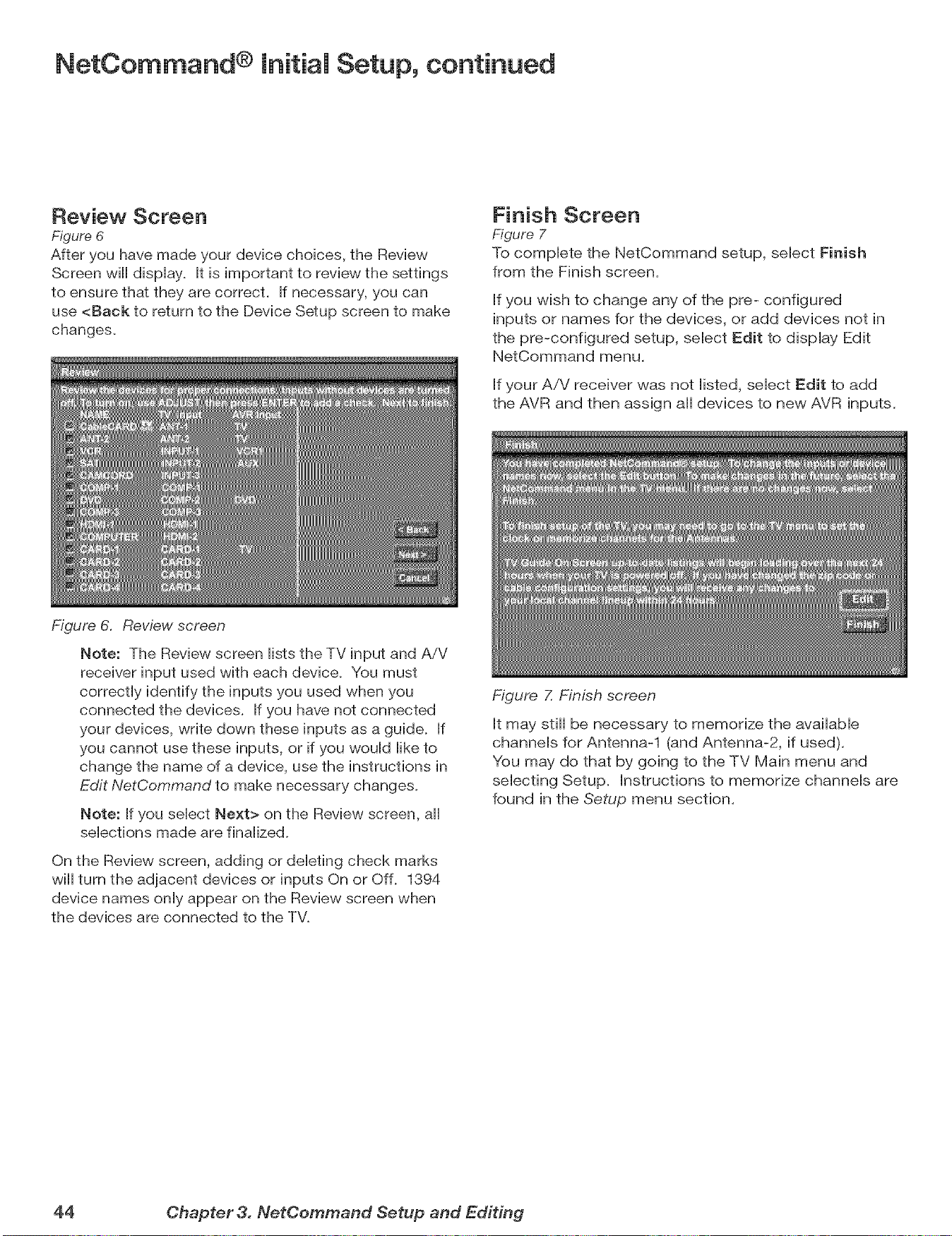
NetCommand ® Initial Setup, continued
Review Screen
Figure 6
After you have made your device choices, the Review
Screen will dispHay. It is important to review the settings
to ensure that they are correct. If necessary, you can
use <Back to return to the Device Setup screen to make
changes.
Finish Screen
Figure 7
To compHete the NetCommand setup, seHect Finish
from the Finish screen.
Hfyou wish to change any of the pre- configured
inputs or names for the devices, or add devices not in
the pre-configured setup, seHect Edit to display Edit
NetCommand menu,
Hfyour A/V receiver was not Histed, seHect Edit to add
the AVR and then assign aH devices to new AVR inputs,
Figure 6. Review screen
Note: The Review screen Histsthe TV input and AiV
receiver input used with each device. You must
correctly identify the inputs you used when you
connected the devices. If you have not connected
your devices, write down these inputs as a guide. If
you cannot use these inputs, or if you would like to
change the name of a device, use the instructions in
Edit NetCommand to make necessary changes.
Note: If you select Next> on the Review screen, all
selections made are finalized.
On the Review screen, adding or deleting check marks
will turn the adjacent devices or inputs On or Off. 1394
device names only appear on the Review screen when
the devices are connected to the TV.
Figure Z Finish screen
It may still be necessary to memorize the available
channels for Antenna-1 (and Antenna-2, if used),
You may do that by going to the TV Main menu and
selecting Setup. Instructions to memorize channels are
found in the Setup menu section,
44 Chapter 3. NetCemmand Setup and Editing
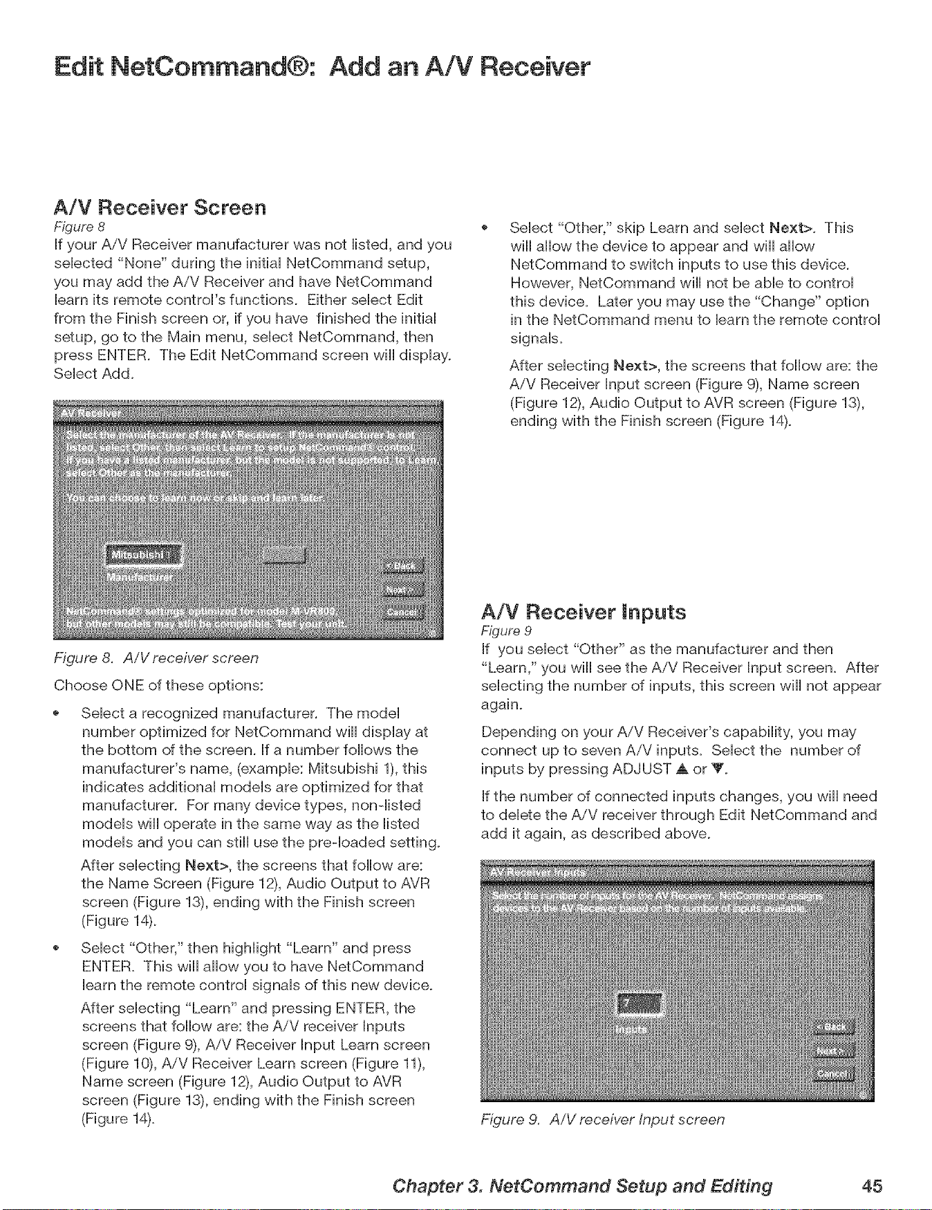
Edit NetCommand®: Add an AiV Receiver
A/V Receiver Screen
Figure 8
If your A/V Receiver manufacturer was not Histed, and you
seHected "None" during the initiaHNetCommand setup,
you may add the A/V Receiver and have NetCommand
Hearnits remote controVs functions. Either seHect Edit
from the Finish screen or, if you have finished the initiaH
setup, go to the Main menu, seHect NetCommand, then
press ENTER. The Edit NetCommand screen will display.
SeHect Add.
Figure 8. AiV receiver screen
Choose ONE of these options:
Select "Other," skip Learn and select Next>. This
will allow the device to appear and will allow
NetCommand to switch inputs to use this device.
However, NetCommand will not be able to control
this device. Later you may use the "Change" option
in the NetCommand menu to learn the remote control
signals.
After selecting Next>, the screens that follow are: the
AiV Receiver Input screen (Figure 9), Name screen
(Figure 12), Audio Output to AVR screen (Figure 13),
ending with the Finish screen (Figure 14).
SeHect a recognized manufacturer. The modeH
number optimized for NetCommand will dispHay at
the bottom of the screen. If a number follows the
manufacturer's name, (example: Mitsubishi 1), this
indicates additional models are optimized for that
manufacturer. For many device types, non-listed
models will operate in the same way as the listed
models and you can still use the preqoaded setting.
After selecting Next>, the screens that follow are:
the Name Screen (Figure 12), Audio Output to AVR
screen (Figure 13), ending with the Finish screen
(Figure 14).
Select "Other," then highlight "Learn" and press
ENTER. This will allow you to have NetCommand
learn the remote control signals of this new device.
After selecting "Learn" and pressing ENTER, the
screens that follow are: the AiV receiver Inputs
screen (Figure 9), AiV Receiver Input Learn screen
(Figure 1% AiV Receiver Learn screen (Figure 11),
Name screen (Figure 12), Audio Output to AVR
screen (Figure 13), ending with the Finish screen
(Figure 14).
A/V Receiver inputs
Figure 9
If you select "Other" as the manufacturer and then
"Learn," you will see the AiV Receiver Input screen. After
selecting the number of inputs, this screen will not appear
again.
Depending on your A/V Receiver's capability, you may
connect up to seven AiV inputs. Select the number of
inputs by pressing ADJUST _k or V.
If the number of connected inputs changes, you will need
to delete the AiV receiver through Edit NetCommand and
add it again, as described above.
Figure 9. AiV receiver Input screen
Chapter 3. NetCommand Setup and Editing 45
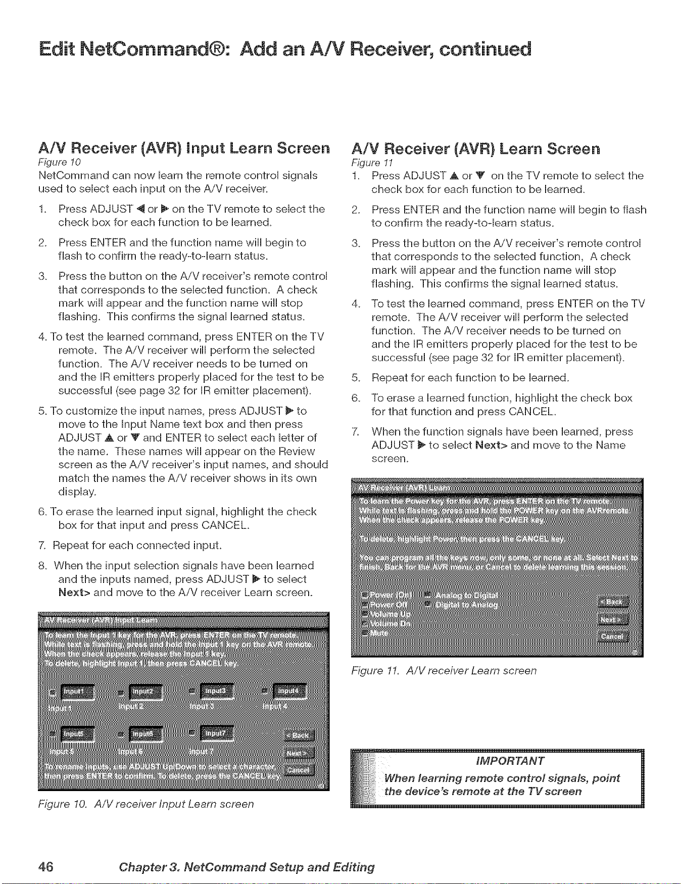
Edit NetCommand®: Add an A!V Receiver, continued
A/V Receiver (AVR) Input Learn Screen
Figure 10
NetCommand can now Heamthe remote centroH signaHs
used to seHect each input on the AiV receiver.
1. Press ADJUST _ or 11_on the TV remote to seHect the
check box for each function to be Heamed.
2. Press ENTER and the function name will begin to
flash to confirm the ready-toqeam status.
3. Press the button en the AiV receiver's remote controH
that corresponds to the seHected function. A check
mark will appear and the functien name will stop
flasMng. This confirms the signaH Hearned status.
4. To test the Hearned command, press ENTER on the TV
remote. The AiV receiver will perform the seHected
function. The AiV receiver needs to be turned on
and the IR emitters properHy pHacedfor the test to be
successfuH (see page 32 for IR emitter placement).
5. To custemize the input names, press ADJUST _ to
move te the Input Name text box and then press
ADJUST A or Y and ENTER to select each letter of
the name. These names will appear en the Review
screen as the AiV receiver's input names, and should
match the names the AiV receiver shows in its own
display.
6. To erase the learned input signal, highlight the check
box for that input and press CANCEL
7. Repeat for each connected input.
8. When the input selection signals have been learned
and the inputs named, press ADJUST 1_to select
Next> and move to the AiV receiver Learn screen.
Figure 10. AiV receiver Input Learn screen
A/V Receiver (AVR) Learn Screen
Figure I1
1. Press ADJUST A or _' on the TV remote to select the
check box for each function to be learned.
2. Press ENTER and the function name will begin to flash
to confirm the ready-toqeam status.
3. Press the button en the A/V receiver's remote control
that corresponds to the selected function, A check
mark will appear and the function name will stop
flashing. This confirms the signal learned status.
4. To test the learned command, press ENTER en the TV
remote. The AiV receiver will perform the selected
function. The AiV receiver needs to be turned on
and the IR emitters properly placed for the test te be
successful (see page 32 for IR emitter placement).
5. Repeat for each function to be learned.
6. To erase a learned function, highlight the check box
for that function and press CANCEL
7. When the function signals have been learned, press
ADJUST _ to select Next> and move to the Name
screen.
Figure 11. AiV receiver Leam screen
iMPORTANT
n learning remote control signals, point
device's remote at the TV scree: n
46 Chapter 3. NetCemmand Setup and Editing
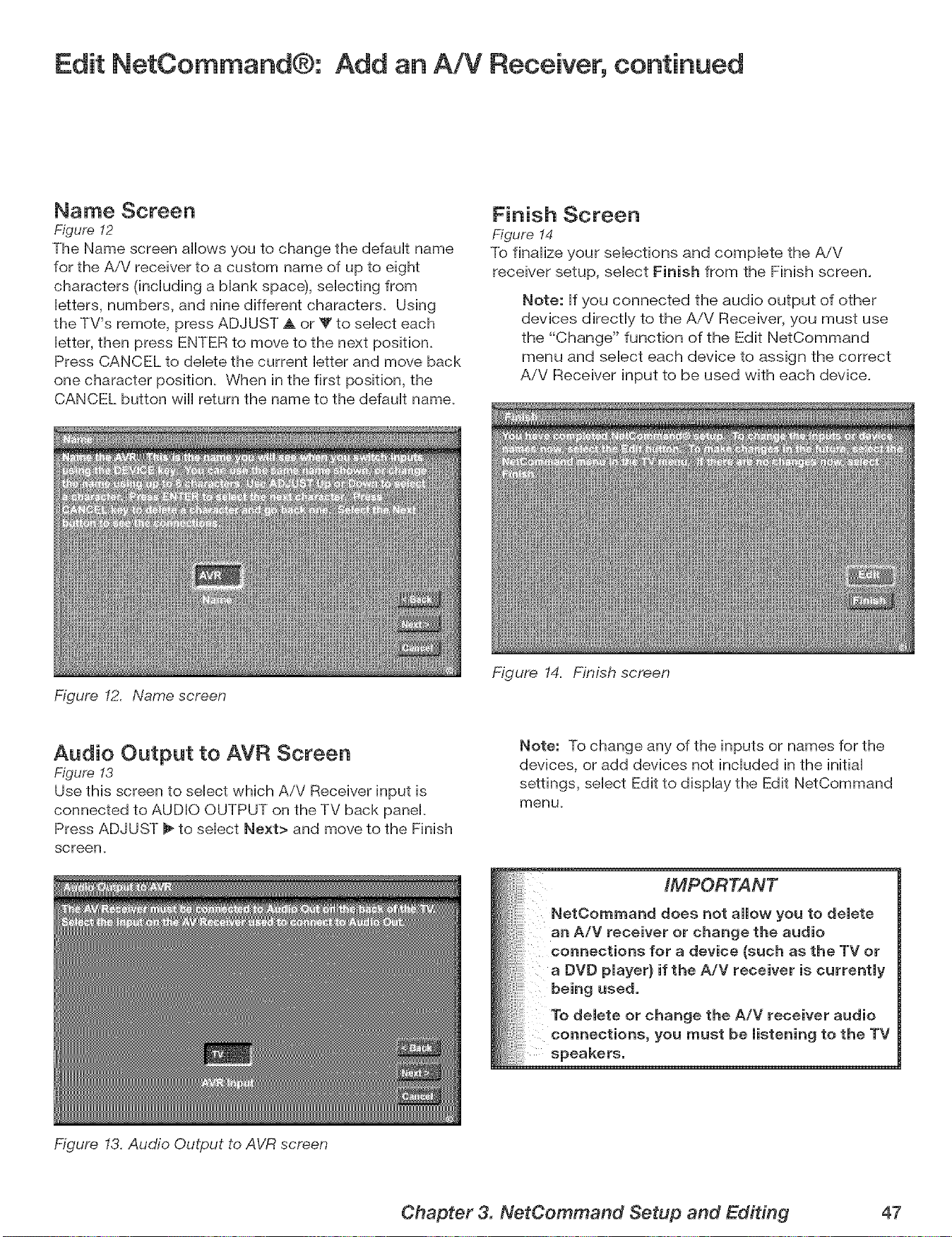
Edit NetCommand®: Add an A!V Receiver, continued
Name Screen
Figure 12
The Name screen allows you to change the defauHt name
for the A/V receiver to a custom name of up to eight
characters 0ncHuding a Mank space), seHecfing from
Hetters, numbers, and nine different characters. Using
the TV's remote, press ADJUST A or V to seHecteach
Hetter,then press ENTER to move to the next position.
Press CANCEL to deHete the current Hetterand move back
one character position. When in the first position, the
CANCEL button will return the name to the defauHt name.
Figure 12. Name screen
Finish Screen
Figure 14
To flnaHize your seHections and compHete the AiV
receiver setup, seHect Finish from the Finish screen.
Note: Hfyou connected the audio output of other
devices directly to the AiV Receiver, you must use
the "Change" function of the Edit NetCommand
menu and select each device to assign the correct
A/V Receiver input to be used with each device.
Audio Output to AVR Screen
Figure 13
Use this screen to select which AiV Receiver input is
connected to AUDIO OUTPUT on the TV back panel.
Press ADJUST _ to select Next> and move to the Finish
screen.
Figure 13. Audio Output to AVR screen
Figure 14. Finish screen
Note: To change any of the inputs or names for the
devices, or add devices not included in the initial
settings, select Edit to display the Edit NetCommand
menu,
IMPORTANT
NetCommand does not allow you to delete
an A/V receiver or change the audio
connections for a device (such as the TV or
a DVD player} if the A/V receiver is currently
being used.
To delete or change the A/V receiver audio
connections, you must be listening to the TV
speakers.
Chapter 3. NetCommand Setup and Editing 47
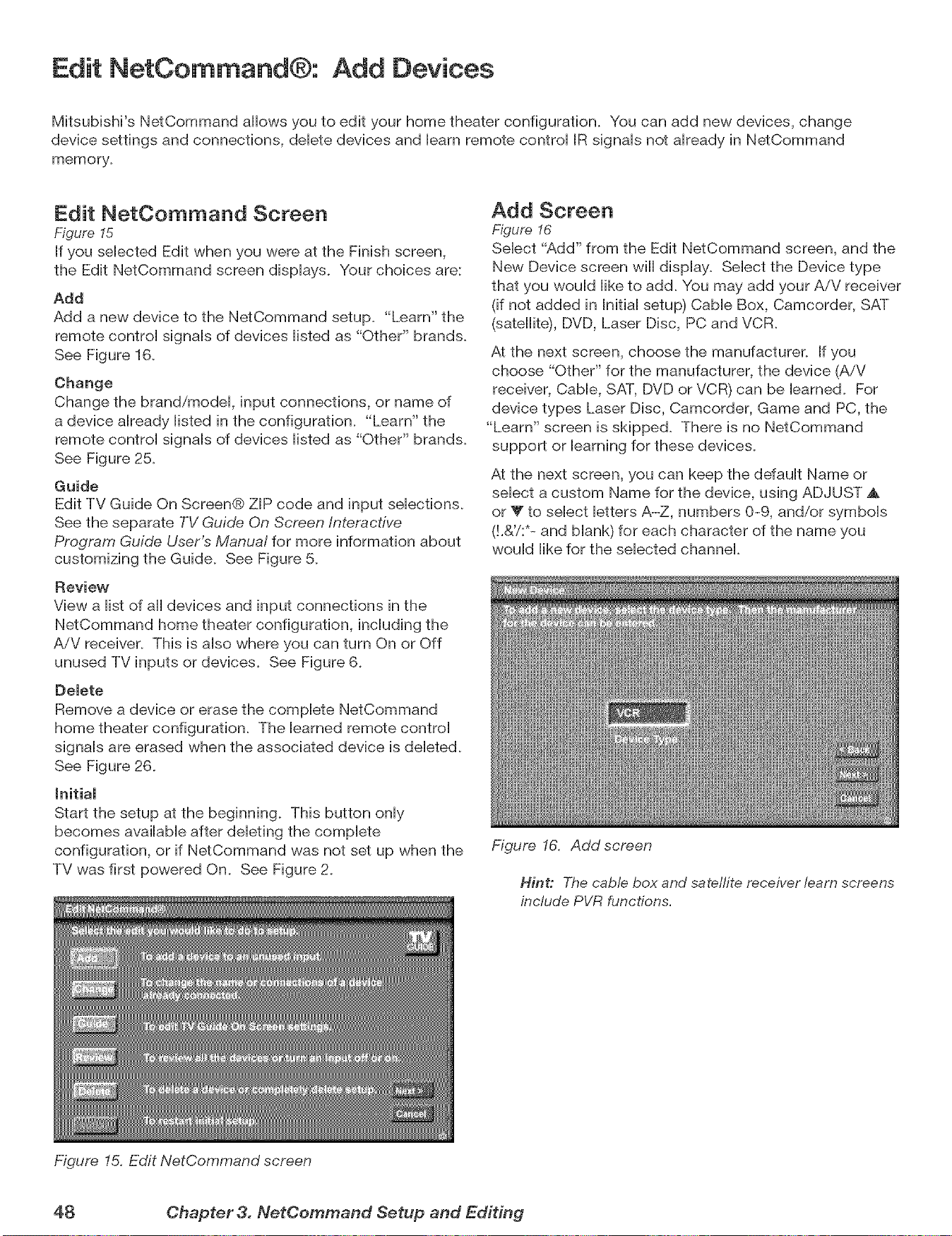
Edit NetCommand®: Add Devices
Mitsubishi's NetCommand allows you to edit your home theater configuration. You can add new devices, change
device settings and connections, deHete devices and Hearnremote controH IR signaHs not aHready in NetCommand
memory.
Edit NetCommand Screen
Figure I5
If you seHected Edit when you were at the Finish screen,
the Edit NetCommand screen dispHays. Your choices are:
Add
Add a new device to the NetCommand setup. "Learn" the
remote controH signaHs of devices Histed as "Other" brands.
See Figure 16.
Change
Change the brand/modeL input connections, or name of
a device aHready Histed in the configuration. "Learn" the
remote controH signaHs of devices Histed as "Other" brands.
See Figure 25.
Guide
Edit TV Guide On Screen® ZIP code and input selections.
See the separate TV Guide On Screen interactive
Program Guide User's Manual for more information about
customizing the Guide. See Figure 5.
Review
View a list of all devices and input connections in the
NetCommand home theater configuration, including the
AiV receiver. This is also where you can turn On or Off
unused TV inputs or devices. See Figure 6.
Delete
Remove a device or erase the complete NetCommand
home theater configuration. The learned remote control
signals are erased when the associated device is deleted.
See Figure 26.
Initial
Start the setup at the beginning. This button only
becomes available after deleting the complete
configuration, or if NetCommand was not set up when the
TV was first powered On. See Figure 2.
Figure 15. Edit NetCommand screen
Add Screen
Figure 16
Select "Add" from the Edit NetCommand screen, and the
New Device screen will display. Select the Device type
that you would like to add. You may add your AiV receiver
(if not added in Initial setup) Cable Box, Camcorder, SAT
(satellite), DVD, Laser Disc, PC and VCR.
At the next screen, choose the manufacturer. If you
choose "Other" for the manufacturer, the device (AiV
receiver, Cable, SAT, DVD or VCR) can be learned. For
device types Laser Disc, Camcorder, Game and PC, the
"Learn" screen is skipped. There is no NetCommand
support or learning for these devices.
At the next screen, you can keep the default Name or
select a custom Name for the device, using ADJUST ,_
or V to select letters A-Z, numbers 0-9, and/or symbols
(!.&'/:*- and blank) for each character of the name you
would like for the selected channel.
Figure 16. Add screen
Hint: The cable box and satellite receiver learn screens
include PVR functions,
48 Chapter 3. NetCemmand Setup and Editing
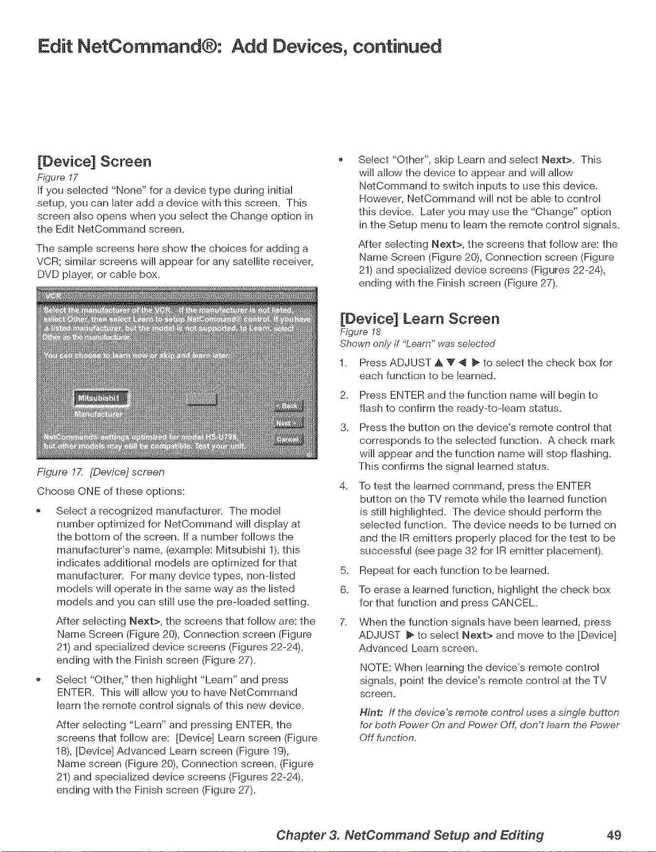
Edit NetCommand®: Add Devices, continued
[Device] Screen
Figure 17
If you seHected "None" for a device type during initiaH
setup, you can Hateradd a device with this screen. This
screen aHsoopens when you seHectthe Change option in
the Edit NetCommand screen.
The sampHe screens here show the choices for adding a
VCR; simiHar screens will appear for any satellite receiver,
DVD pHayer,or cabHe box.
Figure 17. [Device] screen
Choose ONE of these options:
SeHect "Other", skip Learn and seHect Next>. This
will allow the device to appear and will allow
NetCommand to switch inputs to use this device.
However, NetCommand will not be able to control
this device. Later you may use the "Change" option
in the Setup menu to learn the remote control signals.
After selecting Next>, the screens that follow are: the
Name Screen (Figure 2% Connection screen (Figure
21) and specialized device screens (Figures 22-24),
ending with the Finish screen (Figure 27).
Select a recognized manufacturer. The model
number optimized for NetCommand will display at
the bottom of the screen. If a number follows the
manufacturer's name, (example: Mitsubishi 1), this
indicates additional models are optimized for that
manufacturer. For many device types, non-listed
models will operate in the same way as the listed
models and you can still use the preqoaded setting.
After selecting Next>, the screens that follow are: the
Name Screen (Figure 20), Connection screen (Figure
21) and specialized device screens (Figures 22-24),
ending with the Finish screen (Figure 27).
Select "Other," then highlight "Learn" and press
ENTER. This will allow you to have NetCommand
learn the remote control signals of this new device.
After selecting "Learn" and pressing ENTER, the
screens that follow are: [Device] Learn screen (Figure
18), [Device] Advanced Learn screen (Figure 19),
Name screen (Figure 20), Connection screen, (Figure
21) and specialized device screens (Figures 22-24),
ending with the Finish screen (Figure 27).
[Device] Learn Screen
Figure I8
Shown only if "Learn" was selected
1. Press ADJUST ,A _' _ _ to select the check box for
each function to be learned.
2_
3.
Press ENTER and the function name will begin to
flash to confirm the ready-to-learn status.
Press the button on the device's remote control that
corresponds to the selected function. A check mark
will appear and the function name will stop flashing.
This confirms the signal learned status.
4_
To test the learned command, press the ENTER
button on the TV remote while the learned function
is still higHighted. The device should perform the
selected function. The device needs to be turned on
and the IR emitters properly placed for the test to be
successful (see page 32 for IR emitter placement).
5. Repeat for each function to be learned.
6. To erase a learned function, highlight the check box
for that function and press CANCEL
7. When the function signals have been learned, press
ADJUST _ to select Next> and move to the [Device]
Advanced Learn screen.
NOTE: When learning the device's remote control
signals, point the device's remote control at the TV
screen.
Hint: If the device's remote control uses a single button
for both Power On and Power Off, don't learn the Power
Off function,
Chapter 3. NetCommand Setup and Editing 49
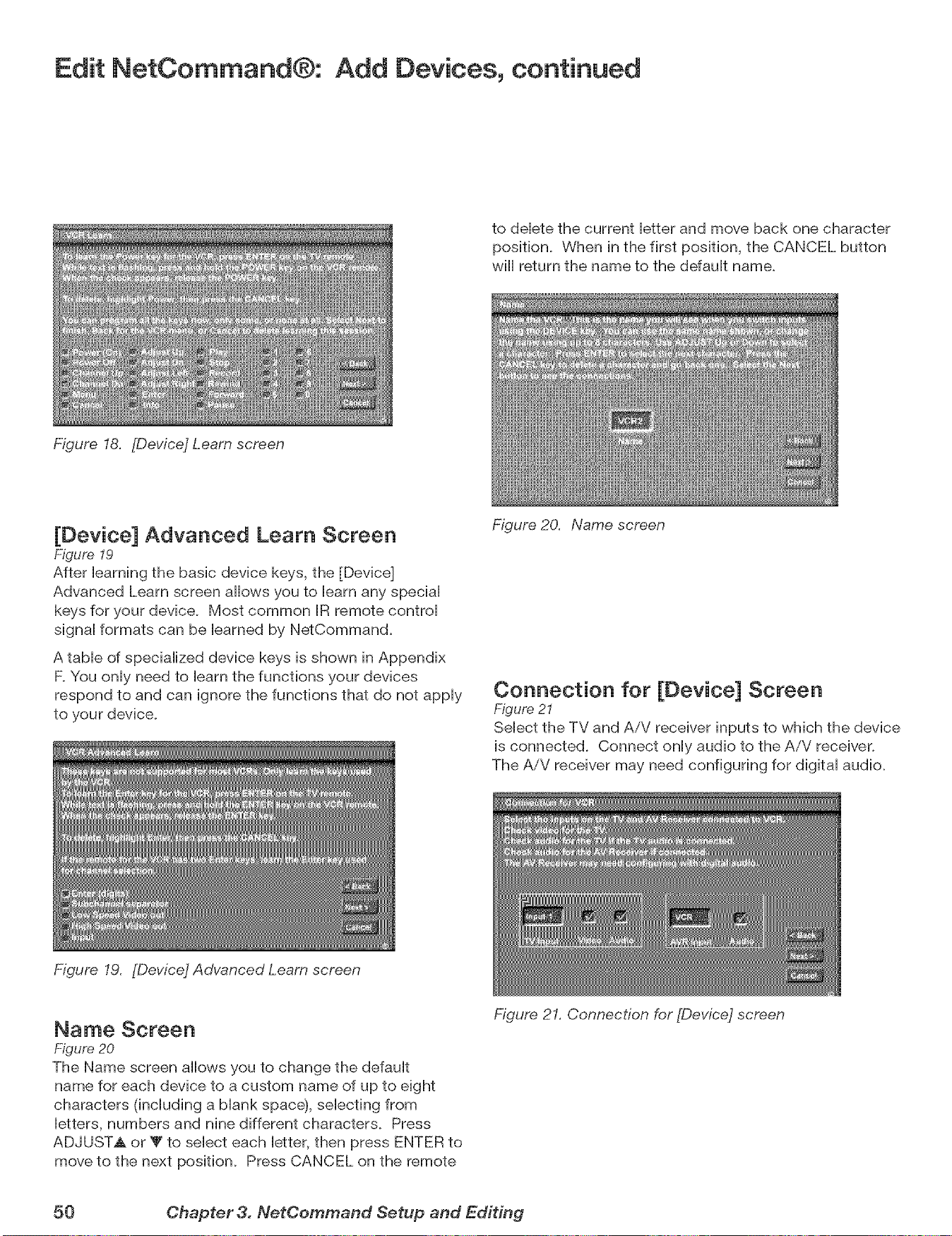
Edit NetCommand®: Add Devices, continued
Figure 18. [Device] Learn screen
to deHetethe current Hetter and move back one character
position. When in the first position, the CANCEL button
wifl return the name to the defauHt name.
[Device] Advanced Learn Screen
Figure 19
After Hearning the basic device keys, the [Device]
Advanced Learn screen allows you to Hearnany speciaH
keys for your device. Most common IR remote controH
signaHformats can be Hearned by NetCommand.
A tame of speciaHized device keys is shown in Appendix
F.You onHyneed to Hearnthe functions your devices
respond to and can ignore the functions that do not appHy
to your device.
Figure 19. [Device] Advanced Learn screen
Figure 20. Name screen
Connection for [Device] Screen
Figure 2I
SeHect the TV and AiV receiver inputs to which the device
is connected. Connect onHyaudio to the AiV receiver.
The AiV receiver may need configuring for digital audio.
Name Screen
Figure 20
The Name screen allows you to change the default
name for each device to a custom name of up to eight
characters (including a blank spacd}, selecting from
letters, numbers and nine different characters. Press
ADJUSTA or T to select each letter, then press ENTER to
move to the next position. Press CANCEL on the remote
Figure 21. Connection for [Device] screen
50 Chapter 3. NefCommand Setup and Editing
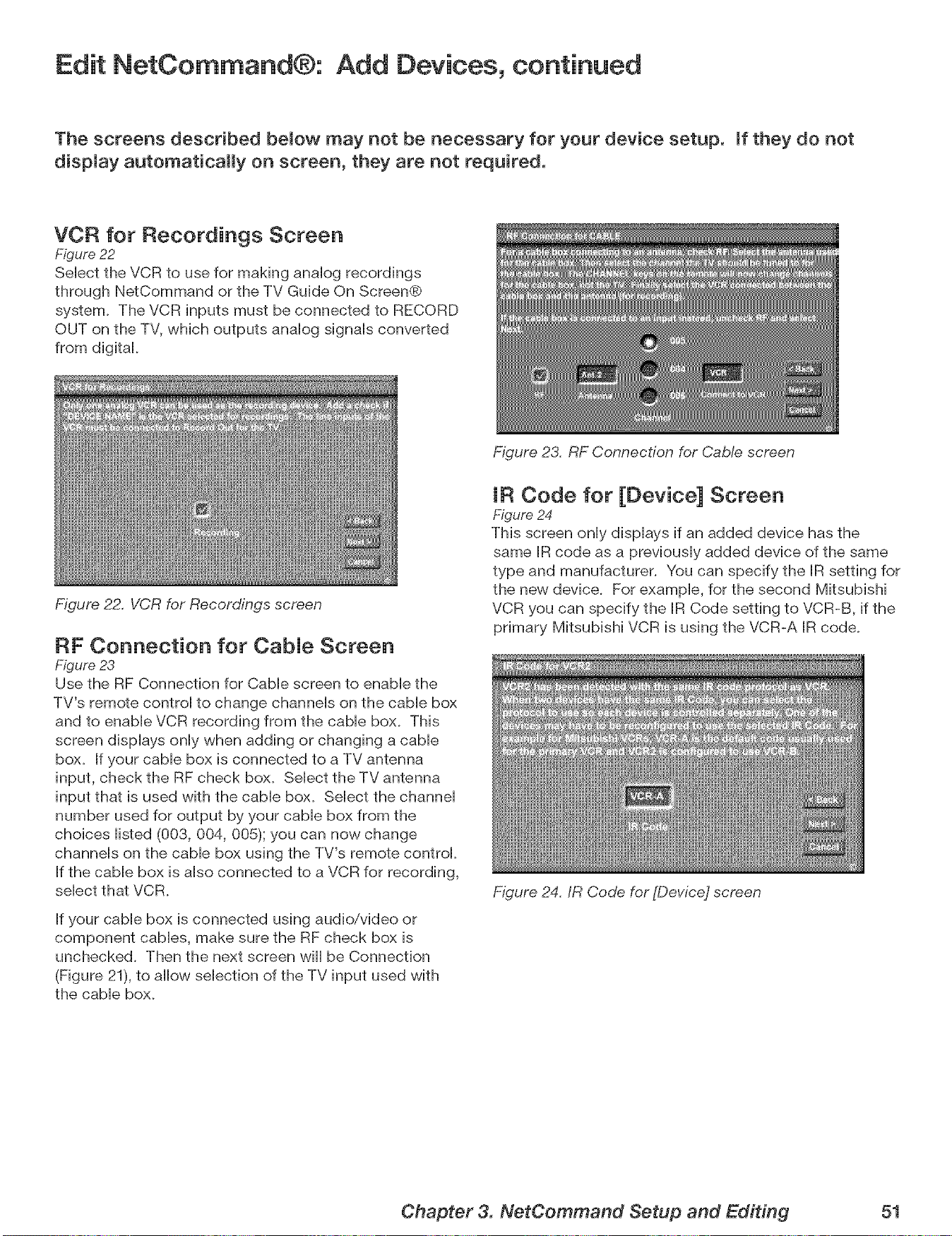
Edit NetCommand®: Add Devices, continued
The screens described bemow may not be necessary for your device setup, mfthey do not
dispmay automatically on screen, they are not required.
VCR for Recordings Screen
Figure 22
SeHect the VCR to use for making anaHog recordings
through NetCommand or the TV Guide On Screen®
system. The VCR inputs must be connected to RECORD
OUT on the TV, which outputs anaHog signaHs converted
from digital
Figure 22. VCR for Recordings screen
RF Connection for CabJe Screen
Figure 23
Use the RF Connection for CabHescreen to enaMe the
TV's remote control to change channeHs on the came box
and to enabHe VCR recording from the came box. This
screen dispHays onHywhen adding or changing a cable
box. If your cable box is connected to a TV antenna
input, check the RF check box. Select the TV antenna
input that is used with the cable box. Select the channel
number used for output by your cable box from the
choices listed (003, 004, 005); you can now change
channels on the cable box using the TV's remote control
If the cable box is also connected to a VCR for recording,
select that VCR.
If your cable box is connected using audio/video or
component cables, make sure the RF check box is
unchecked. Then the next screen will be Connection
(Figure 21), to allow selection of the TV input used with
the cable box.
Figure 23. RF Connection for Cab!e screen
IR Code for [Device] Screen
Figure 24
This screen only displays if an added device has the
same IR code as a previously added device of the same
type and manufacturer. You can specify the IR setting for
the new device. For example, for the second Mitsubishi
VCR you can specify the IR Code setting to VCR-B, if the
primary Mitsubishi VCR is using the VCR-A IR code.
Figure 24. IR Code for [Device] screen
Chapter 3. NetCommand Setup and Editing 51
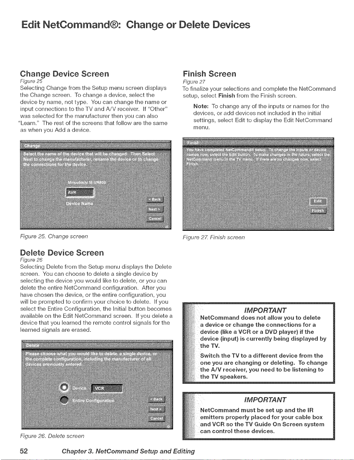
Edit NetCommand®: Change or Delete Devices
Change Device Screen
Figure 25
SeHecting Change from the Setup menu screen dispHays
the Change screen. To change a device, seHectthe
device by name, not type. You can change the name or
input connections to the TV and AiV receiver_ If "Other"
was seHected for the manufacturer then you can aHso
"Learn/' The rest of the screens that follow are the same
as when you Add a device.
Figure 25. Change screen
Finish Screen
Figure 27
To finaHize your seHections and complete the NetCommand
setup, seHect Finish from the Finish screen.
Note: To change any of the inputs or names for the
devices, or add devices not incHuded in the initiaH
settings, seHect Edit to dispHay the Edit NetCommand
menu.
DeJete Device Screen
Figure 26
SeHecflng DeHetefrom the Setup menu displays the Delete
screen. You can choose to delete a single device by
selecting the device you would like to delete, or you can
delete the entire NetCommand configuration. After you
have chosen the device, or the entire configuration, you
will be prompted to confirm your choice to delete. If you
select the Entire Configuration, the Initial button becomes
available on the Edit NetCommand screen. If you delete a
device that you learned the remote control signals for the
learned signals are erased_
Figure 26. Delete screen
Figure 2Z Finish screen
IMPORTANT
NetOommand does not allow you to delete
a device or change the connections for a
device (like a VCR or a DVD player} if the
device (input} is currently being displayed by
the TV.
Switch the TV to a different device from the
or deleting° To change
the A/V receiver, you need to be listening to
_eakers.
52 Chapter 3. NetCemmand Setup and Editing
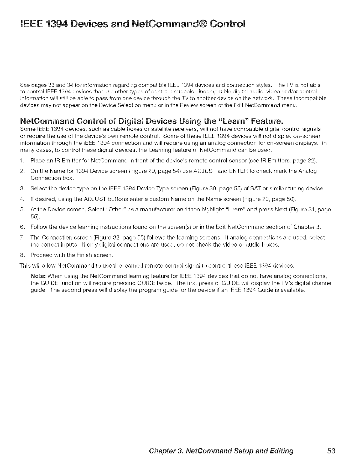
IEEE 1394 Devices and NetCommand® Control
See pages 33 and 34 for information regarding compatible IEEE 1394 devices and connection styles. The TV is not able
to control IEEE 1394 devices that use other types of control protocols. Incompatible digital audio, video and/or control
information will still be able to pass from one device through the TV to another device on the network. These incompatible
devices may not appear on the Device Selection menu or in the Review screen of the Edit NetCommand menu.
NetOommand ControJ of DigitaJ Devices Using the "Learn" Feature.
Some IEEE 1394 devices, such as came boxes or satellite receivers, will not have compatibHe digitaH controH signaHs
or require the use of the device's own remote control Some of these IEEE 1394 devices will not dispHay on-screen
information through the BEEE1394 connection and will require using an analog connection for on-screen displays. In
many cases, to control these digital devices, the Learning feature of NetCommand can be used.
1. Place an IR Emitter for NetCommand in front of the device's remote control sensor (see IR Emitters, page 32).
2. On the Name for 1394 Device screen (Figure 29, page 54) use ADJUST and ENTER to check mark the Analog
Connection box.
3. Select the device type on the IEEE 1394 Device Type screen (Figure 30, page 55) of SAT or similar tuning device
4. If desired, using the ADJUST buttons enter a custom Name on the Name screen (Figure 20, page 50).
5. At the Device screen, Select "Other" as a manufacturer and then highlight "Learn" and press Next (Figure 31, page
55).
6. Follow the device learning instructions found on the screen(s) or in the Edit NetCommand section of Chapter 3.
7. The Connection screen (Figure 32, page 55) follows the learning screens. If analog connections are used, select
the correct inputs. If only digital connections are used, do not check the video or audio boxes.
8. Proceed with the Finish screen.
This will allow NetCommand to use the learned remote control signal to control these IEEE 1394 devices.
Note: When using the NetCommand learning feature for IEEE 1394 devices that do not have analog connections,
the GUIDE function will require pressing GUIDE twice. The first press of GUIDE will display the TV's digital channel
guide. The second press will display the program guide for the device if an IEEE 1394 Guide is available.
Chapter 3. NetCommand Setup and Editing 53
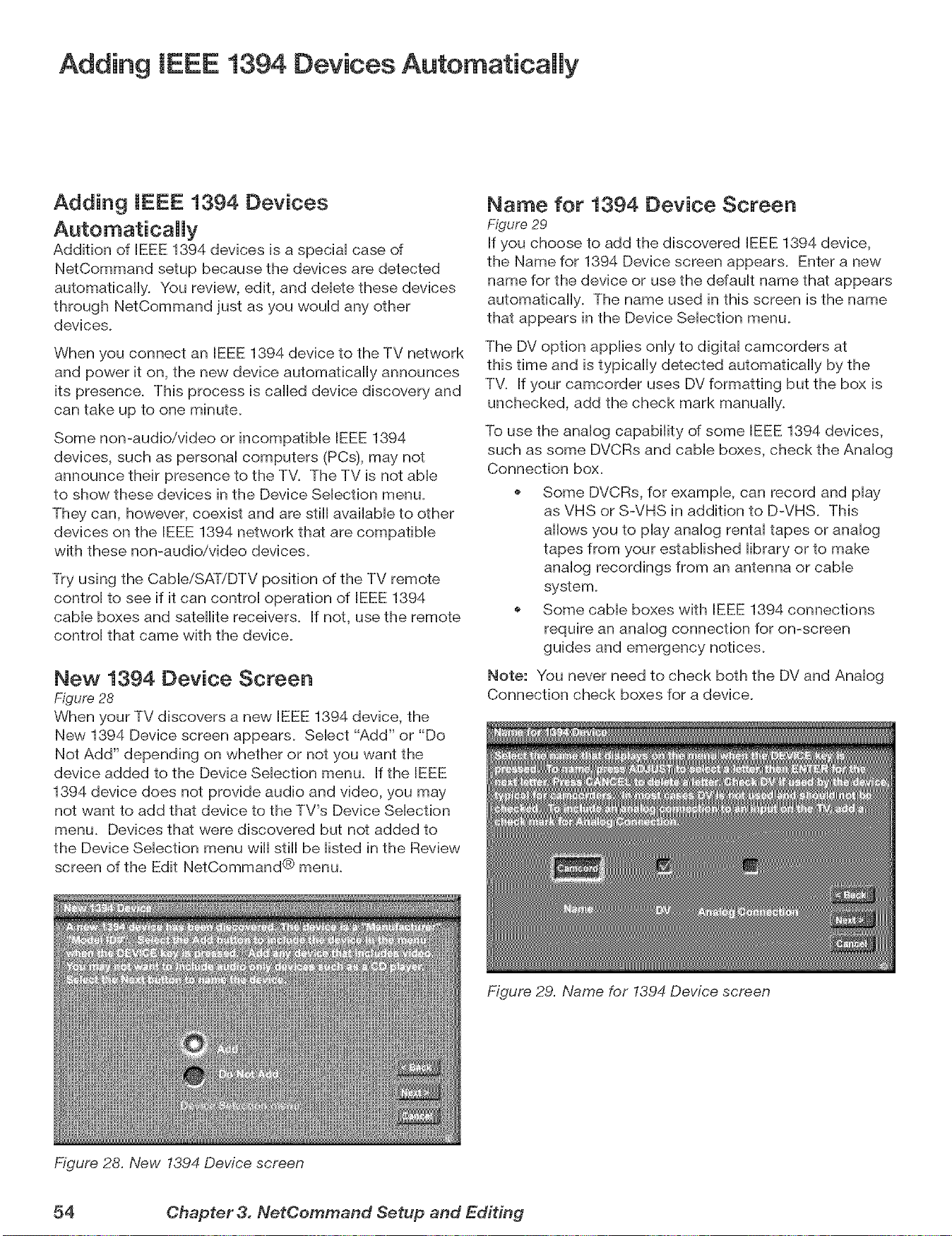
Adding IEEE 1394 Devices Automatically
Adding IEEE 1394 Devices
Addition of IEEE 1394 devices is a speciaH case of
NetCommand setup because the devices are detected
automatically. You review, edit, and deHetethese devices
through NetCommand just as you wouHd any other
devices.
When you connect an IEEE 1394 device to the TV network
and power it on, the new device automatically announces
its presence. This process is called device discovery and
can take up to one minute.
Some non-audio/video or incompatible IEEE 1394
devices, such as personaH computers (PCs), may not
announce their presence to the TV. The TV is not abHe
to show these devices in the Device SeHection menu.
They can, however, coexist and are still available to other
devices on the IEEE 1394 network that are compatible
with these non-audio/video devices.
Try using the CableiSATiDTV position of the TV remote
control to see if it can control operation of IEEE 1394
cable boxes and satellite receivers. If not, use the remote
control that came with the device.
New 1394 Device Screen
Figure 28
When your TV discovers a new IEEE 1394 device, the
New 1394 Device screen appears. Select "Add" or "Do
Not Add" depending on whether or not you want the
device added to the Device Selection menu. If the IEEE
1394 device does not provide audio and video, you may
not want to add that device to the TV's Device Selection
menu. Devices that were discovered but not added to
the Device Selection menu will still be listed in the Review
screen of the Edit NetCommand® menu.
Figure 28. New 1394 Device screen
Name for 1394 Device Screen
Figure 29
If you choose to add the discovered IEEE 1394 device,
the Name for 1394 Device screen appears. Enter a new
name for the device or use the default name that appears
automatically. The name used in this screen is the name
that appears in the Device Selection menu.
The DV option applies only to digital camcorders at
this time and is typically detected automatically by the
TV. If your camcorder uses DV formatting but the box is
unchecked, add the check mark manually.
To use the analog capability of some IEEE 1394 devices,
such as some DVCRs and cable boxes, check the Analog
Connection box.
Some DVCRs, for example, can record and play
as VHS or S-VHS in addition to D-VHS. This
allows you to play analog rental tapes or analog
tapes from your established library or to make
analog recordings from an antenna or cable
system.
Some cable boxes with IEEE 1394 connections
require an analog connection for on-screen
guides and emergency notices.
Note: You never need to check both the DV and Analog
Connection check boxes for a device.
Figure 29. Name for 1394 Device screen
54 Chapter 3. NetCemmand Setup and Editing
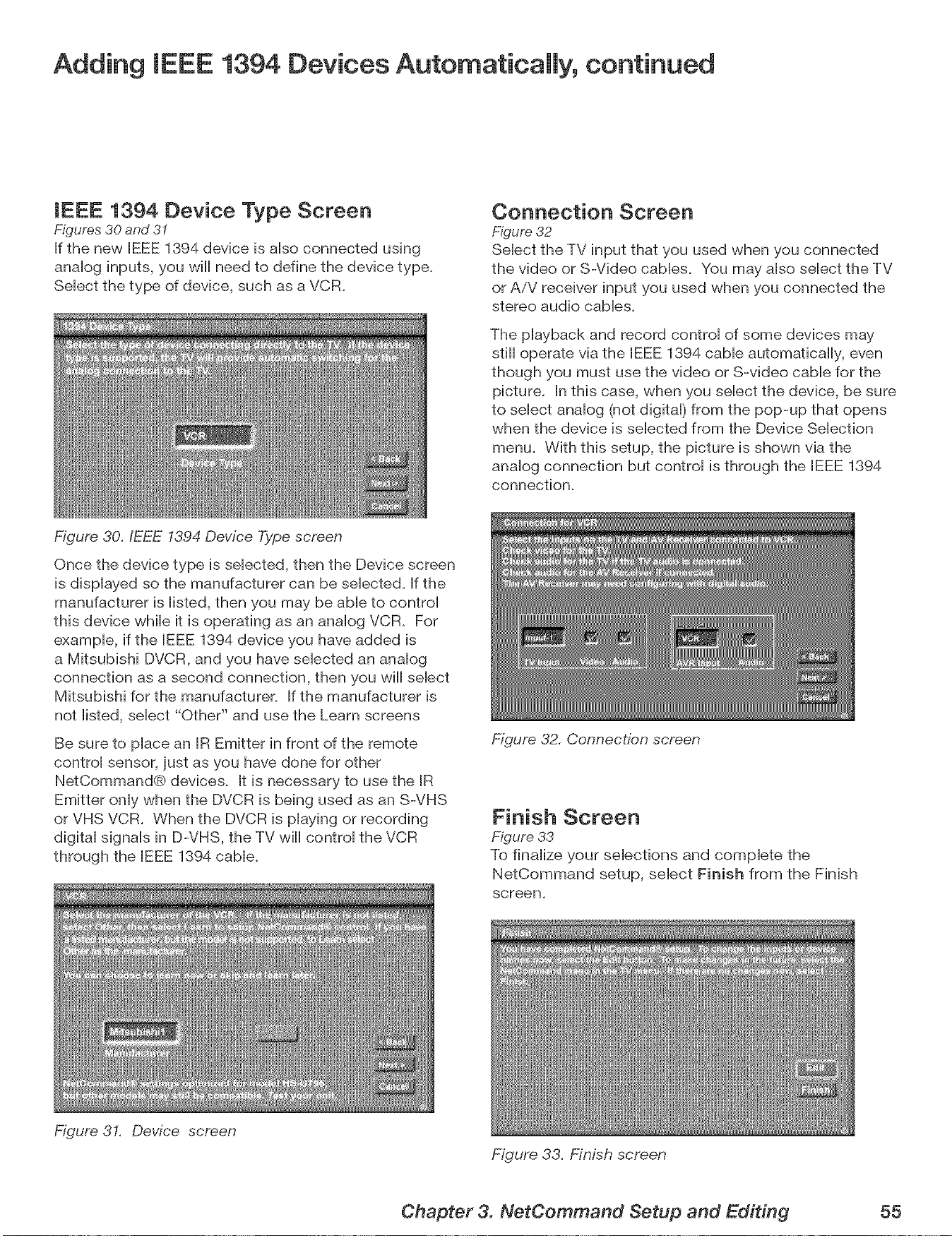
Adding IEEE 1394 Devices Automatically, continued
IEEE 1394 Device Type Screen
Figures 30 and 3I
If the new IEEE 1394 device is aHso connected using
anaHog inputs, you will need to define the device type.
SeHect the type of device, such as a VCR.
Figure 30./EEE 1394 Device Type screen
Connection Screen
Figure 32
SeHect the TV input that you used when you connected
the video oF S-Video caMes. You may aHsoseHect the TV
oF AiV receiver input you used when you connected the
stereo audio cabHes.
The pHayback and record controH of some devices may
still operate via the BEEE1394 cabHe automatically, even
though you must use the video oF S-video came for the
picture. In this case, when you select the device, be sure
to select analog (not digital) from the pop-up that opens
when the device is selected from the Device Selection
menu. With this setup, the picture is shown via the
analog connection but control is through the IEEE 1394
connection.
Once the device type is selected, then the Device screen
is displayed so the manufacturer can be selected. If the
manufacturer is listed, then you may be able to control
this device while it is operating as an analog VCR. For
example, if the IEEE 1394 device you have added is
a Mitsubishi DVCR, and you have selected an analog
connection as a second connection, then you will select
Mitsubishi for the manufacturer. If the manufacturer is
not listed, select "Other" and use the Learn screens
Be sure to place an IR Emitter in front of the remote
control sensor, just as you have done for other
NetCommand® devices. It is necessary to use the IR
Emitter only when the DVCR is being used as an S-VHS
oF VHS VCR. When the DVCR is playing oF recording
digital signals in D-VHS, the TV will control the VCR
through the IEEE 1394 cable.
Figure 31. Device screen
Figure 32. Connection screen
Finish Screen
Figure 33
To finalize your selections and complete the
NetCommand setup, select Finish from the Finish
screen,
Figure 33. Finish screen
Chapter 3. NetCommand Setup and Editing 55

ommand® Functions
Device SeUection Menu ............................... 58
Using the Device Menu Button to DispUay Menus ............. 59
Using the GUIDE Button to Display ChannelView TM and Menus.. o 60
NetCommand®=ControHed Recordings .................... 61
Peer-to-Peer Connections ............................. 63
Using A/V Discs .................................... 64
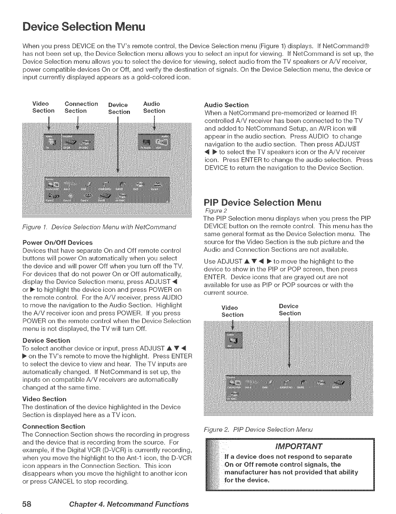
Device Selection Menu
When you press DEVICE on the TV's remote control, the Device Selection menu (Figure 1)displays. If NetCommand®
has not been set up, the Device Selection menu allows you to select an input for viewing. If NetCommand is set up, the
Device Selection menu allows you to select the device for viewing, select audio from the TV speakers or AiV receiver,
power compatible devices On or Off, and verify the destination of signals. On the Device Selection menu, the device or
input currently displayed appears as a gold-colored icon.
Video Connection Device Audio
Section Section Section Section
Figure I. Device Selection Menu with NetCommand
Power On/Off Devices
Devices that have separate On and Off remote control
buttons will power On automatically when you select
the device and will power Off when you turn off the TV.
For devices that do not power On or Off automatically,
display the Device Selection menu, press ADJUST 4
or _ to highlight the device icon and press POWER on
the remote control. For the AiV receiver, press AUDIO
to move the navigation to the Audio Section. Highlight
the AiV receiver icon and press POWER. If you press
POWER on the remote control when the Device Selection
menu is not displayed, the TV will turn Off.
Device Section
To select another device or input, press ADJUST A T 4
on the TV's remote to move the highlight. Press ENTER
to select the device to view and hear. The TV inputs are
automatically changed. If NetCommand is set up, the
inputs on compatible A/V receivers are automatically
changed at the same time.
Video Section
The destination of the device highlighted in the Device
Section is displayed here as a TV icon.
Connection Section
The Connection Section shows the recording in progress
and the device that is recording from the source. For
example, if the Digital VCR (D-VCR) is currently recording,
when you move the highlight to the Ant-1 icon, the DWCR
icon appears in the Connection Section. This icon
disappears when you move the highlight to another icon
or press CANCEL to stop recording.
Audio Section
When a NetCommand pre-memorized or learned IR
controlled AiV receiver has been connected to the TV
and added to NetCommand Setup, an AVR icon will
appear in the audio section. Press AUDIO to change
navigation to the audio section. Then press ADJUST
_ to select the TV speakers icon or the AiV receiver
icon. Press ENTER to change the audio selection. Press
DEVICE to return the navigation to the Device Section.
PIP Device Selection Menu
Figure 2
The PIP Selection menu displays when you press the PIP
DEVICE button on the remote control. This menu has the
same general format as the Device Selection menu. The
source for the Video Section is the sub picture and the
Audio and Connection Sections are not available.
Use ADJUST A Y 4 _ to move the highlight to the
device to show in the PIP or POP screen, then press
ENTER. Device icons that are grayed out are not
available for use as PIP or POP sources or with the
current source.
Video Device
Section Section
Figure 2. PIP Device Se/ection Menu
58 Chapter 4. Netcommand Functions
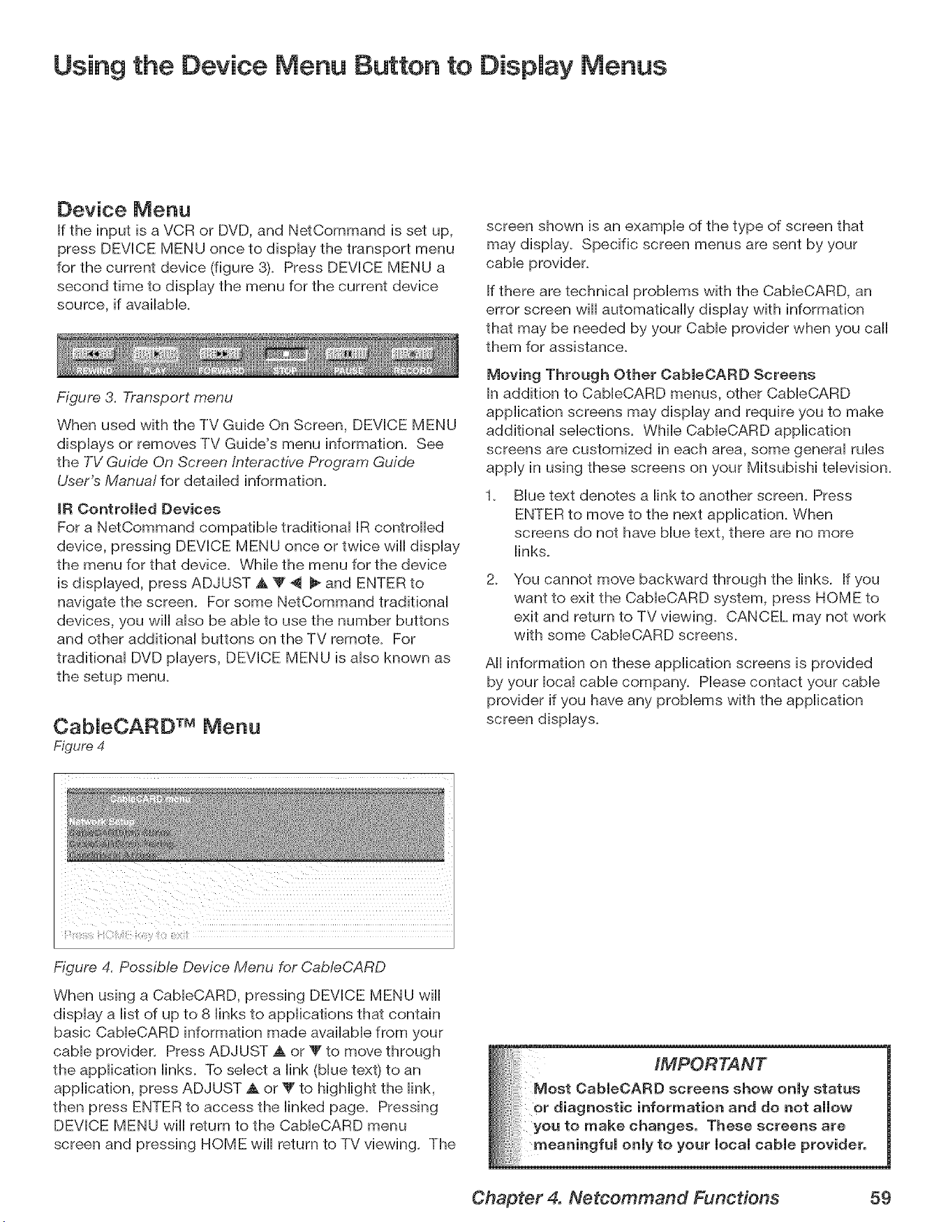
Using the Device Menu Button to Display Menus
Device Menu
If the input is a VCR or DVD, and NetCommand is set up,
press DEVICE MENU once to display the transport menu
for the current device (figure 8). Press DEVICE MENU a
second time to display the menu for the current device
source, if available.
Figure 3. Transport menu
When used with the TV Guide On Screen, DEVICE MENU
displays or removes TV Guide's menu information. See
the TV Guide On Screen Interactive Program Guide
User's Manua! for detailed information.
IR Controlled Devices
For a NetCommand compatible traditional IR controlled
device, pressing DEVICE MENU once or twice wiii display
the menu for that device. While the menu for the device
is displayed, press ADJUST A '_ 4 _ and ENTER to
navigate the screen. For some NetCommand traditional
devices, you wiii also be able to use the number buttons
and other additional buttons on the TV remote. For
traditional DVD players, DEVICE MENU is also known as
the setup menu.
CabJeCARD TM Menu
Figure 4
screen shown is an example of the type of screen that
may display. Specific screen menus are sent by your
cable provider.
If there are technical problems with the CableCARD, an
error screen will automatically display with information
that may be needed by your Cable provider when you caii
them for assistance.
Moving Through Other CableOARD Screens
In addition to CableCARD menus, other CableCARD
application screens may display and require you to make
additional selections. While CableCARD application
screens are customized in each area, some general rubs
apply in using these screens on your Mitsubishi television.
. Blue text denotes a link to another screen. Press
ENTER to move to the next application. When
screens do not have blue text, there are no more
links.
2.
You cannot move backward through the links. If you
want to exit the CableCARD system, press HOME to
exit and return to TV viewing. CANCEL may not work
with some CableCARD screens.
All information on these application screens is provided
by your iocai cable company. Please contact your cable
provider if you have any problems with the application
screen displays.
Figure 4. Possible Device Menu for Cab/eCARD
When using a CabieCARD, pressing DEVICE MENU wiii
display a list of up to 8 links to applications that contain
basic CableCARD information made available from your
cable provider. Press ADJUST A or _' to move through
the application links. To select a link (blue text) to an
application, press ADJUST A or _" to highlight the link,
then press ENTER to access the linked page. Pressing
DEVICE MENU wiii return to the CableCARD menu
screen and pressing HOME wiii return to TV viewing. The
Chapter 4. Netcommand Functions 59
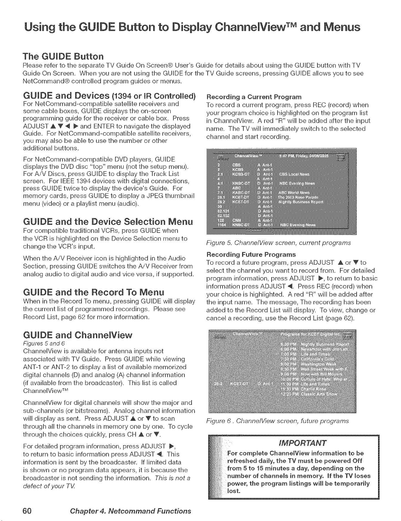
Using the GUIDE Button to Display ChannelView TM and Menus
The GUIDE Button
Please refer to the separate TV Guide On Screen® User's Guide for details about using the GUIDE button with TV
Guide On Screen. When you are not using the GUIDE for the TV Guide screens, pressing GUIDE allows you to see
NetCommand® controlled program guides or menus.
GUIDE and Devices {1394 or mRControlled)
For NetCommand-compatible satellite receivers and
some cable boxes, GUIDE displays the on-screen
programming guide for the receiver or came box. Press
ADJUST A 'V ,_ _ and ENTER to navigate the displayed
Guide. For NetCommand-compatibie satellite receivers,
you may also be able to use the number or other
additional buttons.
Recording a Current Program
To record a current program, press REC (record) when
your program choice is highlighted on the program list
in ChanneiView. A red "R" wii[ be added after the input
name. The TV will immediately switch to the selected
channel and start recording.
For NetCommand-compatible DVD players, GUIDE
displays the DVD disc "top" menu (not the setup menu).
For AiV Discs, press GUIDE to display the Track List
screen. For [EEE 1394 devices with digital connections,
press GUIDE twice to display the device's Guide. For
memory cards, press GUIDE to display a JPEG thumbnail
menu (video) or a playlist menu (audio).
GUIDE and the Device Selection Menu
For compatible traditional VCRs, press GUIDE when
the VCR is highlighted on the Device Selection menu to
change the VCR's input.
When the AiV Receiver icon is highlighted in the Audio
Section, pressing GUIDE switches the A/V Receiver from
analog audio to digital audio and vice versa, if supported.
GUIDE and the Record To Menu
When in the Record To menu, pressing GUIDE will display
the current list of programmed recordings. Please see
Record List, page 62 for more information.
Figure 5. Channe/View screen, current programs
Recording Future Programs
To record a future program, press ADJUST A or _' to
select the channel you want to record from. For detailed
program information, press ADJUST _, to return to basic
information press ADJUST 4. Press REC (record) when
your choice is highlighted. A red "R" will be added after
the input name. The message, The recording has been
added to the Record List will display. To view, change or
cancel a recording, use the Record List (page 62).
GUIDE and Channe[View
Figures 5 and 6
ChannelView is available for antenna inputs not
associated with TV Guide. Press GUIDE while viewing
ANT-1 or ANT-2 to display a list of available memorized
digital channels (D) and analog (A) channel information
(if available from the broadcaste0. This list is called
ChanneIView TM
ChannelView for digital channels wiii show the major and
sub-channels (or bitstreams). Analog channel information
wiii display as sent. Press ADJUST A or T to scan
through all the channels in memory one by one. To cycle
through the choices quickly, press CH A or V_
For detailed program information, press ADJUST _,
to return to basic information press ADJUST 4. This
information is sent by the broadcaster. If limited data
is shown or no program data appears, it is because the
broadcaster is not sending the information. This is not a
defect of your TV.
Figure 6. ChannelView screen, future programs
IMPORTANT
For complete Channe[View information to be
refreshed daily, the TV must be powered Off
from 5 to 15 minutes a day, depending on the
number of channels in memory, if the TV loses
power, the program listings wi[[ be temporarily
lost,
60 Chapter 4. Nefcommand Functions
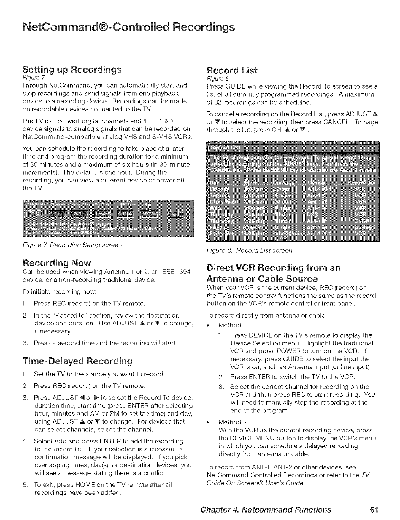
NetCommand®oControHed Recordings
Setting up Recordings
Figure 7
Through NetCommand, you can automatically start and
stop recordings and send signals from one playback
device to a recording device. Recordings can be made
on recordable devices connected to the TV.
The TV can convert digital channels and IEEE 1394
device signals to analog signals that can be recorded on
NetCommand-compatible analog VHS and S-VHS VCRs.
You can schedule the recording to take place at a later
time and program the recording duration for a minimum
of 30 minutes and a maximum of six hours (in 30-minute
increments). The ddault is one hour. During the
recording, you can view a different device or power off
the TV.
Figure Z Recording Setup screen
Record List
Figure 8
Press GUIDE while viewing the Record To screen to see a
list of all currently programmed recordings. A maximum
of 32 recordings can be scheduled.
To cancel a recording on the Record List, press ADJUST A
or _' to select the recording, then press CANCEL. To page
through the list, press CH ,_ or V.
Recording Now
Can be used when viewing Antenna 1 or 2, an IEEE 1394
device, or a non-recording traditional device.
To initiate recording now:
1. Press REC (record) on the TV remote.
2. In the "Record to" section, review the destination
device and duration. Use ADJUST A or _" to change,
if necessary.
3. Press a second time and the recording will start.
Time-DeJayed Recording
1. Set the TV to the source you want to record.
2 Press REC (record) on the TV remote.
3. Press ADJUST "_ or _ to select the Record To device,
duration time, start time (press ENTER after selecting
hour, minutes and AM or PM to set the time) and day,
using ADJUST ,A or _Fto change. For devices that
can select channels, select the channel.
4. Select Add and press ENTER to add the recording
to the record list. If your selection is successful, a
confirmation message will be displayed. If you pick
overlapping times, day(s), or destination devices, you
will see a message stating there is a conflict.
5. To exit, press HOME on the TV remote after all
recordings have been added.
Figure 8. Record List screen
Direct VCR Recording from an
Antenna or CabJe Source
When your VCR is the current device, REC (record) on
the TV's remote control functions the same as the record
button on the VCR's remote control or front panel.
To record directly from antenna or cable:
Method 1
1. Press DEVICE on the TV's remote to display the
Device Selection menu. Highlight the traditional
VCR and press POWER to turn on the VCR. If
necessary, press GUIDE to select the input the
VCR is on, such as Antenna input (or line input).
2. Press ENTER to switch the TV to the VCR.
3. Select the correct channel for recording on the
VCR and then press REC to start recording. You
will need to manually stop the recording at the
end of the program
Method 2
With the VCR as the current recording device, press
the DEVICE MENU button to display the VCR's menu,
in which you can schedule a delayed recording
directly from antenna or cable.
To record from ANT-l, ANT-2 or other devices, see
NetCommand Controlled Recordings or refer to the TV
Guide On Screen® User's Guide.
Chapter 4. Netcommand Functions 61
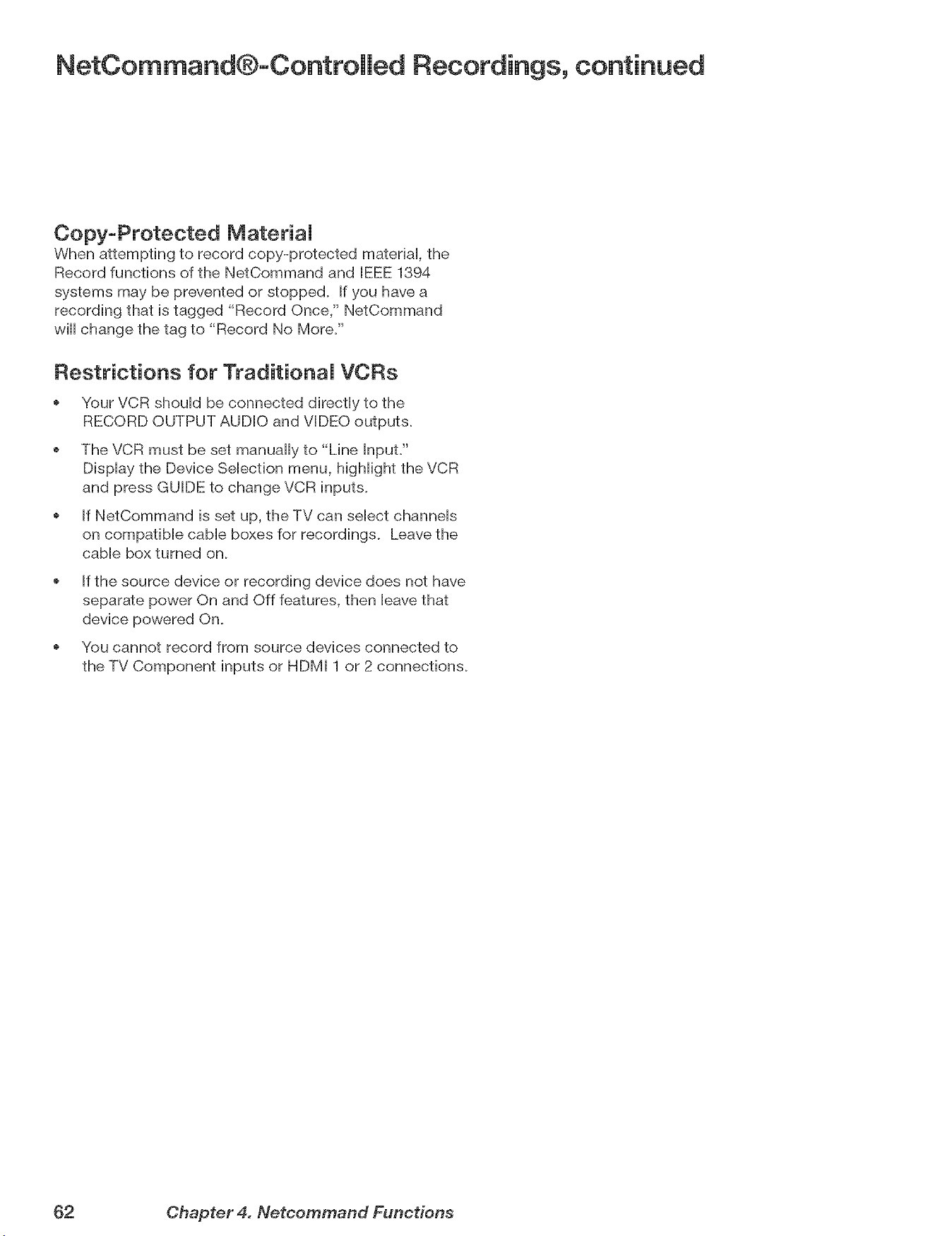
NetCommand®-Controlled Recordings, continued
Copy-Protected MateriaJ
When attempting to record copy-protected materiai, the
Record functions of the NetCommand and EEE 1394
systems may be prevented or stopped. If you have a
recording that is tagged "Record Once," NetCommand
will change the tag to "Record No More."
Restrictions for TraditionaJ VCRs
Your VCR should be connected directly to the
RECORD OUTPUT AUDIO and VIDEO outputs.
The VCR must be set manually to "Line Input."
Display the Device Selection menu, highlight the VCR
and press GUIDE to change VCR inputs.
If NetCommand is set up, the TV can select channels
on compatible cable boxes for recordings. Leave the
cable box turned on.
If the source device or recording device does not have
separate power On and Off features, then leave that
device powered On.
o You cannot record from source devices connected to
the TV Component inputs or HDMI 1 or 2 connections.
62 Chapter 4. Netcommand Functions
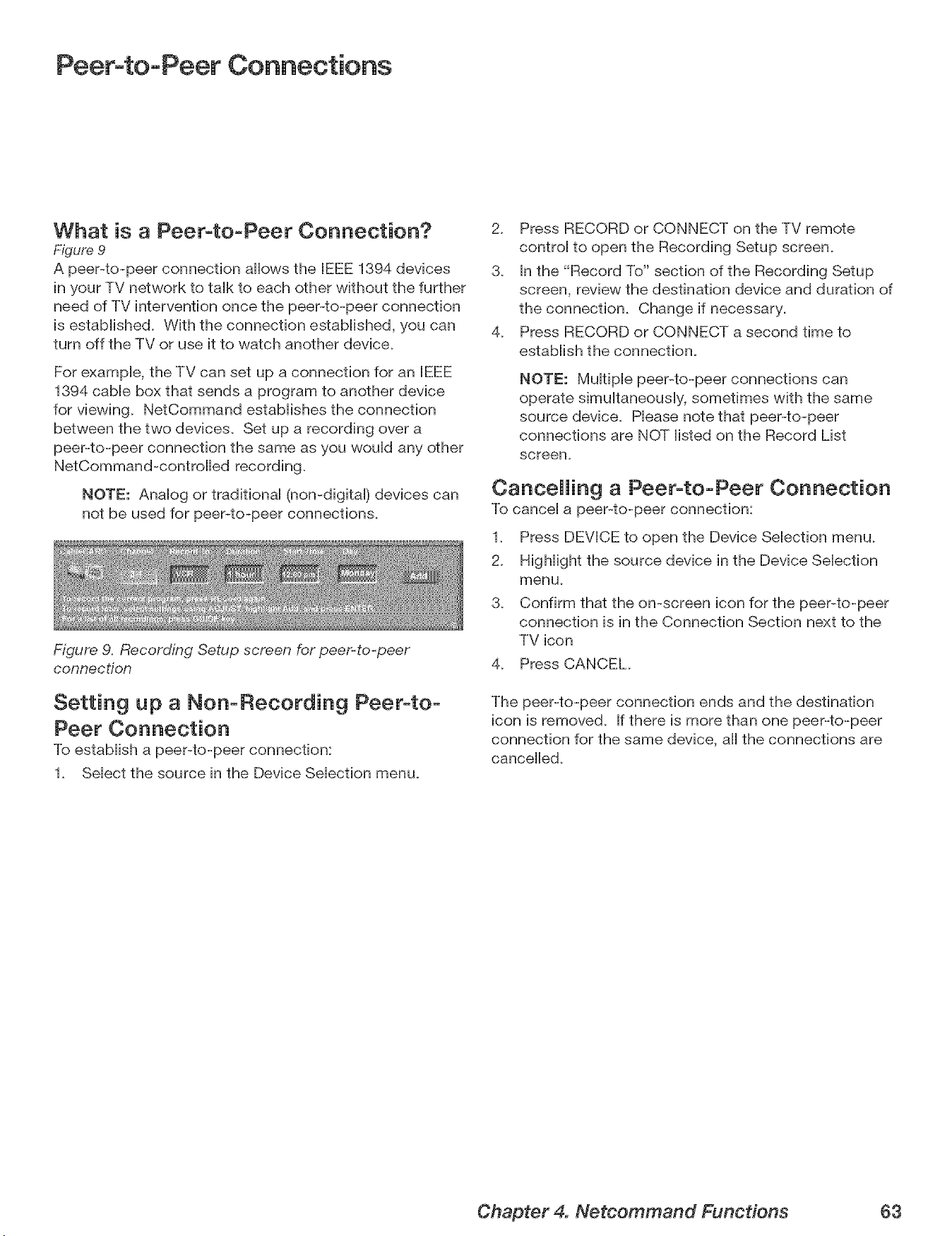
Peer-to-Peer Connections
What is a Peer-to-Peer Connection?
Figure 9
A peePto-peer connection allows the IEEE 1394 devices
in your TV network to taik to each other without the further
need of TV intervention once the peePto-peer connection
is estaMished. With the connection estabiished, you can
turn off the TV or use it to watch another device.
For exampb, the TV can set up a connection for an IEEE
1394 came box that sends a program to another device
for viewing. NetCommand estaMishes the connection
between the two devbes. Set up a recording over a
peer-to-peer connection the same as you wouid any other
NetCommand-controHed recording.
NOTE: Anaiog or tradifionai (non-digitai) devices can
not be used for peer-to-peer connections.
Figure 9. Recording Setup screen for peer-to-peer
connection
Setting up a Non-Recording Peer-to-
Peer Connection
To estaMish a peePto-peer connection:
1_ Select the source in the Device Selection menu.
2_ Press RECORD or CONNECT on the TV remote
control to open the Recording Setup screen.
3_ In the "Record To" section of the Recording Setup
screen, review the destination device and duration of
the connection. Change if necessary.
4_ Press RECORD or CONNECT a second time to
establish the connection.
NOTE: Multiple peePto-peer connections can
operate simultaneously, sometimes with the same
source device. Please note that peer-to-peer
connections are NOT listed on the Record List
screen.
Cancelling a Peer-to-Peer Connection
To cancel a peePto-peer connection:
1_ Press DEVICE to open the Device Selection menu.
2_ Highlight the source device in the Device Selection
menu_
3. Confirm that the on-screen icon for the peer-to-peer
connection is in the Connection Section next to the
TV icon
4_ Press CANCEL
The peer-to-peer connection ends and the destination
icon is removed. If there is more than one peer-to-peer
connection for the same device, all the connections are
cancelled.
Chapter 4. Netcommand Functions 63
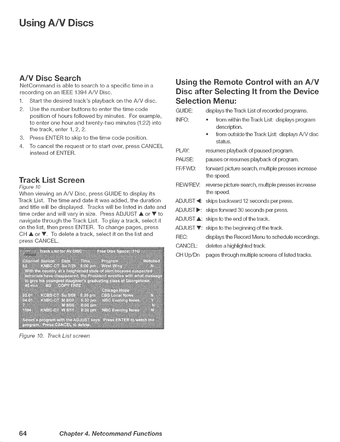
Using A/V Discs
A/V Disc Search
NetCommand is abHeto search to a specific time in a
recording on an JEEE1394 AiV Disc_
1_ Start the desired track's pHayback on the AiV disc,
2_ Use the number buttons to enter the time code
position of hours foHHowedby minutes, For exampHe,
to enter one hour and twenty-two minutes (1:22) into
the track, enter 1, 2, 2_
3_ Press ENTER to skip to the time code position,
4_ To canceH the request or to start over, press CANCEL
instead of ENTER,
Track List Screen
Figure 10
When viewing an AiV Disc, press GUIDE to dispHay its
Track List, The time and date it was added, the duration
and tithe wiHHbe dispHayed, Tracks wiHHbe Histed in date and
time order and wiHHvary in size, Press ADJUST A or Y to
navigate through the Track LisL To pHaya track, seHect it
on the Hist,then press ENTER, To change pages, press
CH A or _'_ To deHete a track, seHect it on the Histand
press CANCEL
Figure 10. Track List screen
Using the Remote ControJ with an A/V
Disc after SeJecting it from the Device
SeJection Menu:
GU JDE: dispHaysthe Track List of recorded pr(xgrams,
INFO: _ from within the Track List: dispHaysprogram
description,
from outsidetheTrack List: dispHaysAiVdisc
status,
PLAY: resumes pHaybackof paused program,
PAUSE: pauses or resumes pHaybackof program,
FEiFWD: forward picture search, muHtipHepresses increase
the speed,
REWiREV: reverse picture search, muHtipHepresses increase
the speed,
ADJUST 4: skips backward 12 seconds per press,
ADJUST _: skips forward 30 seconds per press,
ADJUST _k: skips to the end of the track
ADJUST V: skips to the beginning of the track
REC: dispHaysthe Record Menu to scheduHerecordings,
CANCEL: deHetesa highHightedtrack,
CH UpiDn pages through muHtipHescreens of Histedtracks,
64 Chapter 4. Netcommand Functions
TV
ns
Main Menu ........................................ 66
Setup Menu ....................................... 67
NetCommand® Menu ................................ 69
Record Menu ...................................... 70
ChanneU Menu ..................................... 72
Captions Menu ..................................... 74
V-Chip Lock Menu ................................. 76
Audio/Video Menu .................................. 79
Audio Settings ..................................... 80
Video Settings ..................................... 81
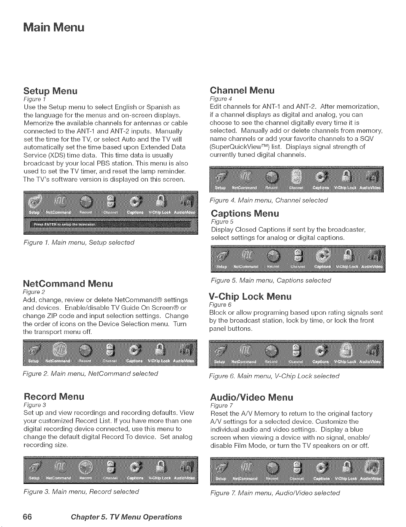
Main Menu
Setup Menu
Figure 1
Use the Setup menu to sebct Engiish or Spanish as
the ianguage for the menus and on-screen dispiays.
Memorize the avaiiabb channeis for antennas or came
connected to the ANT-1 and ANT-2 inputs. Manually
set the time for the TV, or sebct Auto and the TV will
automatically set the time based upon Extended Data
Service (XDS) time data. This time data is usually
broadcast by your iocai PBS stafion. This menu is aiso
used to set the TV timer, and reset the iamp reminder.
The TV's software version is dispiayed on this screen.
Figure I. Main menu, Setup selected
ChanneJ Menu
Figure 4
Edit channeb for ANT-1 and ANT-2. After memorization,
if a channei dispiays as digital and analog, you can
choose to see the channel digitally every time it is
sebcted. Manually add or delete channels from memory,
name channels or add your favorite channels to a SQV
(SuperQuickView TM) list. Displays signal strength of
currently tuned digital channeb.
Figure 4. Main menu, Channel selected
Captions Menu
Figure 5
Display Closed Captions if sent by the broadcaster,
select settings for analog or digital captions.
NetOommand Menu
Figure 2
Add, change, review or delete NetCommand® settings
and devices. Enabb/disabb TV Guide On Screen® or
change ZIP code and input selection settings. Change
the order of icons on the Device Selection menu. Turn
the transport menu of L
Figure 2. Main menu, NetCornrnand selected
Figure 5. Main menu, Captions selected
V-Chip Lock Menu
Figure 6
Block or allow programing based upon rating signals sent
by the broadcast station, lock by time, or lock the front
panel buttons.
Record Menu
Figure 3
Set up and view recordings and recording defaults. View
your customized Record List. If you have more than one
digital recording device connected, use this menu to
change the default digital Record To device. Set analog
recording size.
Figure 3. Main menu, Record selected
Figure 6. Main menu, V-Chip Lock selected
Audio/Video Menu
Figure 7
Reset the AiV Memory to return to the original factory
AiV settings for a selected device. Customize the
individual audio and video settings. Display a blue
screen when viewing a device with no signal, enable/
disable Film Mode, or turn the TV speakers on or of L
Figure 7. Main menu, Audio/Video selected
(}6 Chapter 5. TV Menu Operations
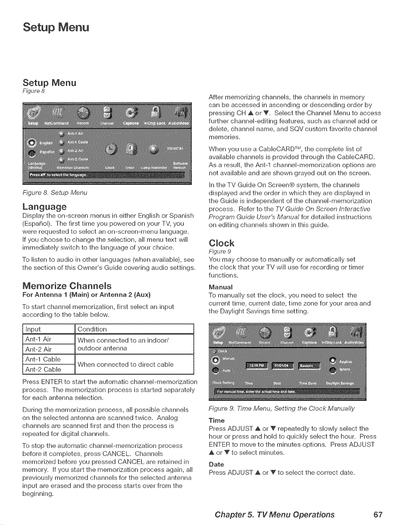
Setup Menu
Setup Menu
Figure 8
Figure 8. Setup Menu
DispUaythe on-screen menus in either Engiish or Spanish
(Espa6oi). The first time you powered on your TV, you
were requested to seiect an on-screen-menu ianguage.
If you choose to change the sebcfion, aH menu text will
immedbteiy switch to the ianguage of your chobe.
To listen to audio in other languages (when available), see
the section of this Owner's Guide covering audio settings.
Memorize ChanneJs
For Antenna 1 (Main} or Antenna 2 (Aux}
To start channe] memorization, first sebct an input
according to the tabb bellow.
Input
Ant-1 Air
Ant-2 Air
Ant-1 CaMe
Ant-2 Cabie
Condition
When connected to an indoor/
outdoor antenna
When connected to direct cable
Press ENTER to start the automatic channel-memorization
process. The memorization process is started separately
for each antenna selection.
During the memorization process, all possible channels
on the selected antenna are scanned twice. Analog
channels are scanned first and then the process is
repeated for digital channels.
To stop the automatic channel-memorization process
before it completes, press CANCEL Channels
memorized before you pressed CANCEL are retained in
memory. If you start the memorization process again, all
previously memorized channels for the selected antenna
input are erased and the process starts over from the
beginning.
After memorizing channels, the channels in memory
can be accessed in ascending or descending order by
pressing CH _, or _'. Select the Channel Menu to access
further channel-editing features, such as channel add or
delete, channel name, and SQV custom favorite channel
memories_
When you use a CableCARD TM, the complete list of
available channels is provided through the CableCARD.
As a result, the Ant-1 channel-memorization options are
not available and are shown grayed out on the screen.
In the TV Guide On Screen@ system, the channels
displayed and the order in which they are displayed in
the Guide is independent of the channel-memorization
process. Refer to the TV Guide On Screen Interactive,
Program Guide User's Manual for detailed instructions
on editing channels shown in this guide.
CJock
Figure 9
You may choose to manually or automatically set
the clock that your TV will use for recording or timer
functions.
Manual
To manually set the clock, you need to select the
current time, current date, time zone for your area and
the Daylight Savings time setting.
Figure 9. Time Menu, Setting the Clock Manually
Time
Press ADJUST _, or Y repeatedly to slowly select the
hour or press and hold to quickly select the hour. Press
ENTER to move to the minutes options. Press ADJUST
A or T to select minutes.
Date
Press ADJUST A or _" to select the correct date.
Chapter 5. TV Menu Operations 67
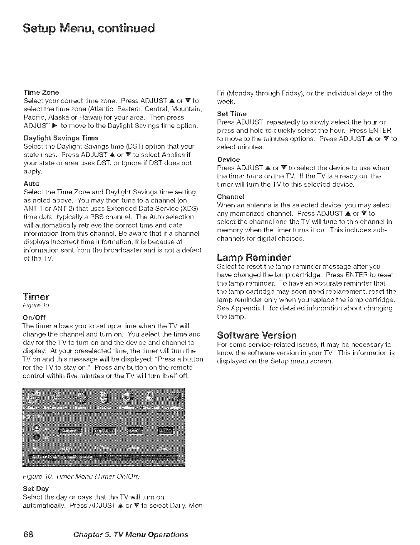
Setup Menu, continued
Time Zone
Select your correct time zone. Press ADJUST A or V to
select the time zone (Atlantic, Eastern, Central, Mountain,
Pacific, Alaska or Hawaii) for your area. Then press
ADJUST _ to move to the Daylight Savings time option.
Daylight Savings Time
Select the Daylight Savings time (DST) option that your
state uses. Press ADJUST A or V to select Applies if
your state or area uses DST, or Ignore if DST does not
apply.
Auto
Select the Time Zone and Daylight Savings time setting,
as noted above. You may then tune to a channel (on
ANT-1 or ANT-2) that uses Extended Data Service (XDS)
time data, typically a PBS channel. The Auto selection
will automatically retrieve the correct time and date
information from this channel. Be aware that if a channel
displays incorrect time information, it is because of
information sent from the broadcaster and is not a defect
of the TV.
Figure 10
On/Off
The timer allows you to set up a time when the TV will
change the channel and turn on. You select the time and
day for the TV to turn on and the device and channel to
display. At your preselected time, the timer wiii turn the
TV on and this message wiii be displayed: "Press a button
for the TV to stay on/' Press any button on the remote
control within five minutes or the TV wiii turn itself of L
Fri (Monday through Friday), or the individual days of the
week.
Set Time
Press ADJUST repeatedly to slowly select the hour or
press and hold to quickly select the hour. Press ENTER
to move to the minutes options. Press ADJUST a, or V to
select minutes.
Device
Press ADJUST _, or Y to select the device to use when
the timer turns on the TV. If the TV is already on, the
timer wiii turn the TV to this selected device.
Channel
When an antenna is the selected device, you may select
any memorized channel. Press ADJUST A or V to
select the channel and the TV will tune to this channel in
memory when the timer turns it on. This includes sub-
channels for digital choices.
Lamp Reminder
Select to reset the lamp reminder message after you
have changed the lamp cartridge. Press ENTER to reset
the lamp reminder. To have an accurate reminder that
the lamp cartridge may soon need replacement, reset the
lamp reminder only when you replace the lamp cartridge.
See Appendix H for detailed information about changing
Software Version
For some service-reiated issues, it may be necessary to
know the software version in your TV. This information is
dispiayed on the Setup menu screen.
Figure 10. Timer Menu (Timer On/Off)
Set Day
Sebct the day or days that the TV will turn on
automatbaHy. Press ADJUST A or _' to sebct Daiiy, Mon-
68 Chapter 5. TV Menu Operations
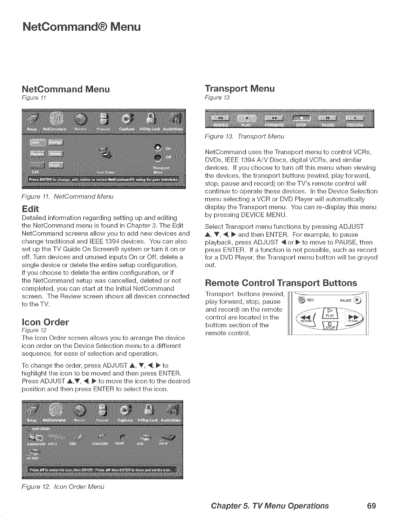
NetCommand® Menu
NetCommand Menu
Figure 11
Figure 11. NetCommand Menu
Transport Menu
Figure !3
DetaiHed information regarding setting up and editing
the NetCommand menu is found in Chapter3. The Edit
NetCommand screens allow you to add new devices and
change tradiflonaH and IEEE 1394 devices. You can aHso
set up the TV Guide On Screen® system or turn it on or
off. Turn devices and unused inputs On or Off, deHete a
singHedevice or deHetethe entire setup configuration.
If you choose to delete the entire configuration, or if
the NetCommand setup was cancelled, deleted or not
completed, you can start at the BnitiaHNetCommand
screen. The Review screen shows aHdevices connected
to the TV.
icon Order
Figure I2
The Icon Order screen allows you to arrange the device
icon order on the Device Selection menu to a different
sequence, for ease of selection and operation.
To change the order, press ADJUST A, _', ._, I_ to
highlight the icon to be moved and then press ENTER.
Press ADJUST ,_,T, 4, _ to move the icon to the desired
position and then press ENTER to select the icon.
Figure 12. Icon Order Menu
Figure 13. Transport Menu
NetCommand uses the Transport menu to control VCRs,
DVDs, IEEE 1394 AiV Discs, digital VCRs, and similar
devices. If you choose to turn off this menu when viewing
the devices, the transport buttons (rewind, play forward,
stop, pause and record) on the TV's remote control will
continue to operate these devices. In the Device Selection
menu selecting a VCR or DVD Player will automatically
display the Transport menu. You can re-display this menu
by pressing DEVICE MENU.
Select Transport menu functions by pressing ADJUST
A, _', 4, _ and then ENTER. For example, to pause
playback, press ADJUST _ or _ to move to PAUSE, then
press ENTER. If a function is not possible, such as record
for a DVD Player, the Transport menu button will be grayed
out.
Remote ControJ Transport Buttons
Transport buttons (rewind,
play forward, stop, pause
and record) on the remote
control are located in the
bottom section of the
remote control.
Chapter 5. TV Menu Operations 69
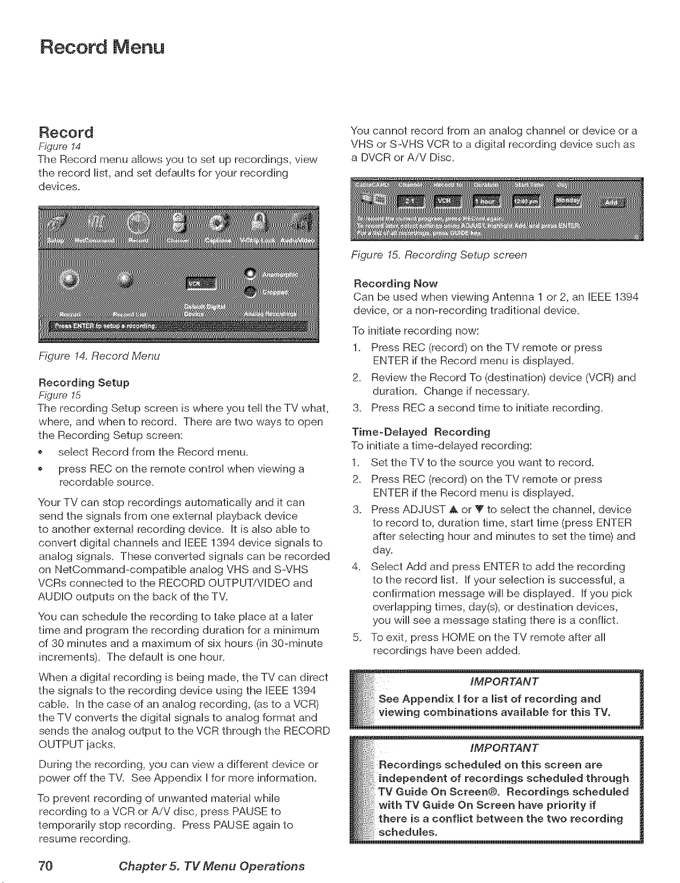
Record Menu
Record
Figure 14
The Record menu allows you to set up recordings, view
the record iist, and set defauits for your recording
devbes.
Figure 14. Record Menu
You cannot record from an anaiog channei or device or a
VHS or S-VHS VCR to a digitai recording device such as
a DVCR or AiV Disc.
Recording Setup
Figure 15
The recording Setup screen is where you tell the TV what,
where, and when to record. There are two ways to open
the Recording Setup screen:
sebct Record from the Record menu.
press REC on the remote controi when viewing a
recordabb source_
Your TV can stop recordings automatically and it can
send the signals from one external playback device
to another external recording device. It is also able to
convert digital channels and IEEE 1394 device signals to
analog signals. These converted signals can be recorded
on NetCommand-compatible analog VHS and S-VHS
VCRs connected to the RECORD OUTPUT/VIDEO and
AUDIO outputs on the back of the TV.
You can schedule the recording to take place at a later
time and program the recording duration for a minimum
of 30 minutes and a maximum of six hours (in 30-minute
increments). The default is one hour.
When a digital recording is being made, the TV can direct
the signals to the recording device using the IEEE 1394
cable. In the case of an analog recording, (as to a VCR)
the TV converts the digital signals to analog format and
sends the analog output to the VCR through the RECORD
OUTPUT jacks.
During the recording, you can view a different device or
power off the TV. See Appendix I for more information.
To prevent recording of unwanted material while
recording to a VCR or AiV disc, press PAUSE to
temporarily stop recording. Press PAUSE again to
resume recording.
Figure 15. Recording Setup screen
Recording Now
Can be used when viewing Antenna 1 or 2, an IEEE 1394
device, or a non-recording traditional device.
To initiate recording now:
1. Press REC (record) on the TV remote or press
ENTER if the Record menu is displayed.
2. Review the Record To (destination) device (VCR) and
duration. Change if necessary.
3. Press REC a second time to initiate recording.
Time=Delayed Recording
To initiate a time-delayed recording:
1. Set the TV to the source you want to record.
2. Press REC (record) on the TV remote or press
ENTER if the Record menu is displayed.
3. Press ADJUST _ or _' to select the channel, device
to record to, duration time, start time (press ENTER
after selecting hour and minutes to set the time) and
day.
4. Select Add and press ENTER to add the recording
to the record list. If your selection is successful, a
confirmation message wiii be displayed. If you pick
overlapping times, day(s), or destination devices,
you will see a message stating there is a conflict.
5. To exit, press HOME on the TV remote after all
recordings have been added.
iMPORTANT
Recordings scheduled on this screen are
independent of recordings scheduled through
TV Guide On Screen@. Recordings scheduled
with TV Guide On Screen have priority if
there is a conflict between the two recording
schedules.
70 Chapter 5. TV Menu Operations
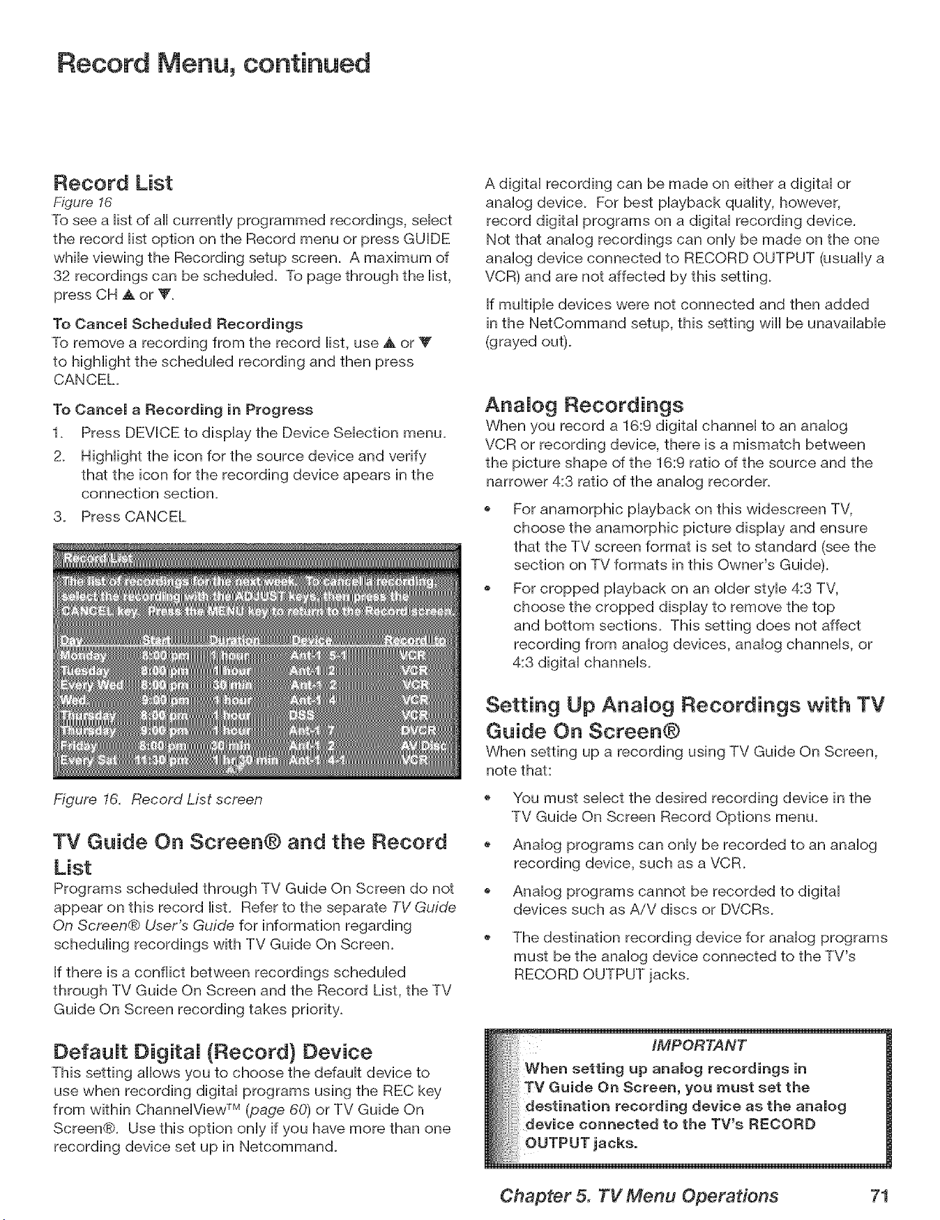
Record Menu, continued
Record List
Figure 16
To see a iist of aHcurrently programmed recordings, sebct
the record iist option on the Record menu or press GUIDE
whib viewing the Recording setup screen. A maximum of
32 recordings can be schedubd. To page through the iist,
press CH A or V.
To Cancel Scheduled Recordings
To remove a recording from the record iist, use A or Y
to higMight the schedubd recording and then press
CANCEL.
To Cancel a Recording in Progress
1. Press DEVICE to dispiay the Device Sebction menu.
2. HigHight the icon for the source device and verify
that the icon for the recording device apears in the
connection section.
3. Press CANCEL
Figure 16. Record List screen
TV Guide On Screen@ and the Record
List
Programs schedubd through TV Guide On Screen do not
appear on this record list. Refer to the separate TV Guide
On Screen® User's Guide for information regarding
scheduling recordings with TV Guide On Screen.
If there is a conflict between recordings scheduled
through TV Guide On Screen and the Record List, the TV
Guide On Screen recording takes priority.
DefauJt DigitaJ (Record} Device
This setting allows you to choose the default device to
use when recording digital programs using the REC key
from within ChannelView TM (page 60) or TV Guide On
Screen®. Use this option only if you have more than one
recording device set up in Netcommand.
A digital recording can be made on either a digital or
analog device. For best playback quality, however,
recorddigitalprograms on a digitalrecordingdevice.
Not thatanalog recordingscan onlybe made on the one
analogdeviceconnected to RECORD OUTPUT (usuallya
VCR) and arenotaffectedby thissetting.
If multiple devices were not connected and then added
in the NetCommand setup, this setting wiii be unavailable
(grayed out).
Aria Jog Recordings
When you record a 16:9 digital channel to an analog
VCR or recording device, there is a mismatch between
the picture shape of the 16:9 ratio of the source and the
narrower 4:3 ratio of the analog recorder.
For anamorphic playback on this widescreen TV,
choose the anamorphic picture display and ensure
that the TV screen format is set to standard (see the
section on TV formats in this Owner's Guide).
For cropped playback on an older style 4:3 TV,
choose the cropped display to remove the top
and bottom sections. This setting does not affect
recording from analog devices, analog channels, or
4:3 digital channels.
Setting Up AnaJog Recordings with TV
Guide On Screen@
When setting up a recording using TV Guide On Screen,
note that:
You must select the desired recording device in the
TV Guide On Screen Record Options menu.
Analog programs can only be recorded to an analog
recording device, such as a VCR.
Analog programs cannot be recorded to digital
devices such as AiV discs or DVCRs.
The destination recording device for analog programs
must be the analog device connected to the TV's
RECORD OUTPUT jacks.
Chapter 5. TV Menu Operations 71
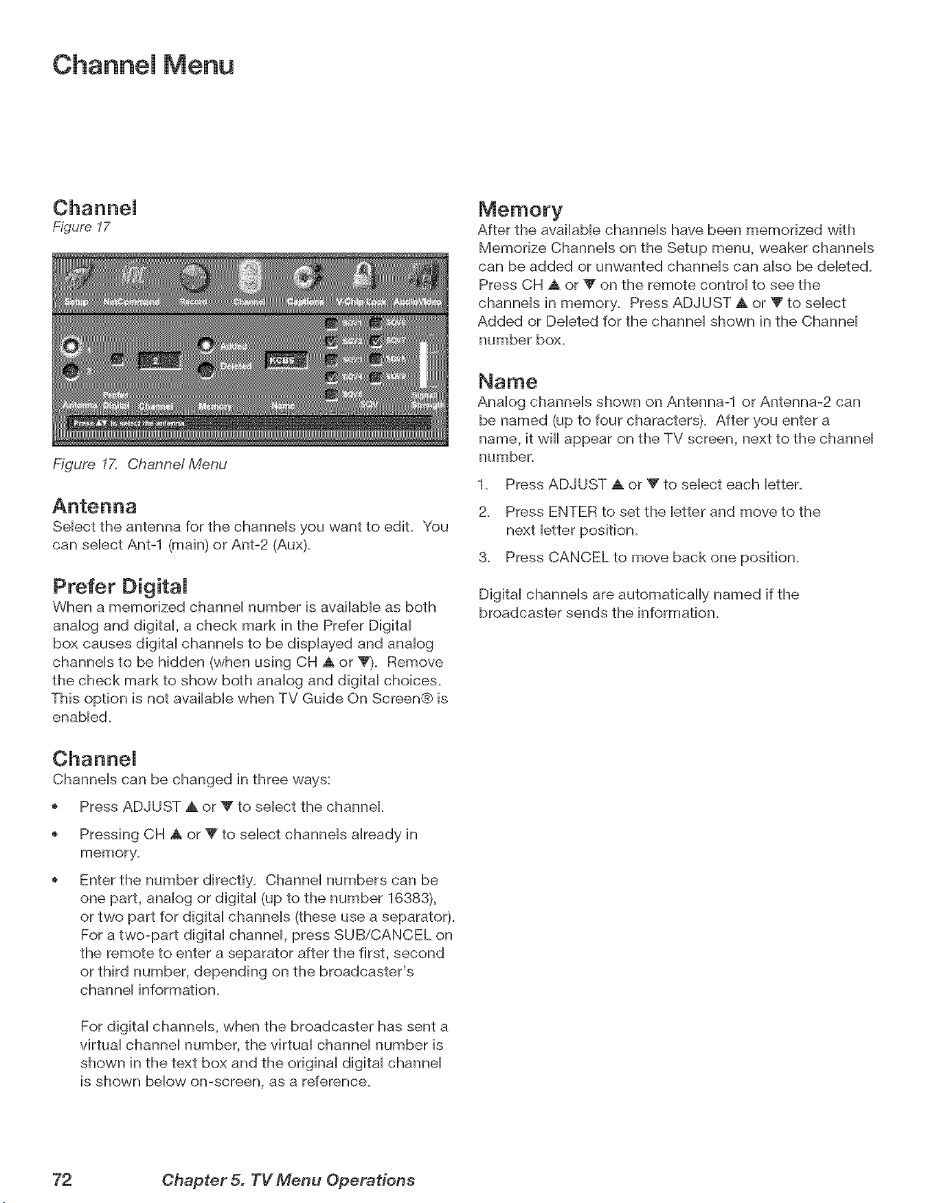
Channel Menu
Figuye 17
Figure 17. Channe! Menu
After the avaiiaMe channeis have been memorized with
Memorize Channeis on the Setup menu, weaker channeis
can be added or unwanted channeis can aiso be debted.
Press CH _k or V on the remote controi to see the
channeb in memory. Press ADJUST A or V to sebct
Added or Debted for the channei shown in the Channei
number box.
Sebct the antenna for the channeis you want to edit. You
can sebct Ant-1 (main) or Ant-2 (Aux).
Prefer DigitaJ
When a memorized channei number is avaiiabb as both
anaiog and digitai, a check mark in the Prefer Digitai
box causes digitai channeis to be dispiayed and anaiog
channeb to be hidden (when using CH A or V). Remove
the check mark to show both analog and digital choices.
This option is not available when TV Guide On Screen® is
enabled.
Analog channels shown on Antenna-1 or Antenna-2 can
be named (up to four characters). After you enter a
name, it will appear on the TV screen, next to the channel
number.
1. Press ADJUST A or Y to select each letter.
2. Press ENTER to set the letter and move to the
next letter position.
3. Press CANCEL to move back one position.
Digital channels are automatically named if the
broadcaster sends the information.
Channels can be changed in three ways:
Press ADJUST A or _' to select the channel
Pressing CH A or V to select channels already in
memory.
Enter the number directly. Channel numbers can be
one part, analog or digital (up to the number 16383),
or two part for digital channels (these use a separator).
For a two-part digital channel, press SUB/CANCEL on
the remote to enter a separator after the first, second
or third number, depending on the broadcaster's
channel information.
For digital channels, when the broadcaster has sent a
virtual channel number, the virtual channel number is
shown in the text box and the original digital channel
is shown below on-screen, as a reference.
72 Chapter 5. TV Menu Operations
Channel Menu, continued
SQV (SuperQuickView TM)
Using The Menu Screen
Figure 17
SQV (SuperQuickView TM) allows you to put together lists
of your favorite channels from Antenna 1 and Antenna
2. You can store channels in any of the 9 different SQV
memory banks. You can also store the same channel in
multiple memory banks. Once you have added a channel
to an SQV memory, "SQV" and the memory bank
number will appear under the tuned channel number on
the TV screen.
Adding SQV Channems
1. Select the Phannel using the "Channel" option box or
press CH A or Y.
2_ Highlight the bank (SQV1-SQVg).
3_ Press ENTER to check mark the selected SQV memory
bank.
4_ Repeat for additional channels or banks.
Removing SQV Channels
1. Highlight the box for the SQV bank number.
2. Press ENTER to remove the check mark.
SQV (SuperQuickView TM)
Using The Remote Control
Viewing and changing SQV banks using the remote
control:
1_ Press the SQV button.
2. To change memory banks, press a number button
within 5 seconds of pressing the SQV button.
3. Press the SQV button repeatedly to cycle through the
channels available in that bank.
Adding SQV channels using the remote control:
1_ Press CH ,A, V, or number buttons to select the
channel you want to add to the current SQV memory
bank.
2_
Press and hold the SQV button for about 2 seconds.
When "SQV" and the memory bank number
appear under the channel number, the channel has
successfully been added.
Removing SQV channels using the remote control:
1. Press the SQV button and then the memory bank
number.
2. Press the SQV button repeatedly until you see the
desired channel.
3_
While the channel number and SQV indicator (with
correct bank number) are still displayed on the
screen, press the CANCEL button. If the CANCEL
button is not pressed before the SQV indicator
disappears automatically, the channel wiii not be
removed.
4. When the SQV indicator disappears, the channel
has successfully been removed only from that bank.
"Other" banks remain unchanged_
SignaJ Strength
Displays the approximate signal strength of the currently
tuned digital channel. Use this indicator to help you
adjust the antenna direction for optimal signal strength.
The higher the bar, the stronger the signal. Does not
apply to analog channels.
You can change the tuned channel while in this menu so
that you can see the effects of antenna adjustments. To
change the channel, either:
Highlight the channel box, press CH A Y or ADJUST
A V to display the desired channel number, and
press ENTER.
Enter the channel number on the remote control and
press ENTER.
Chapter 5. TV Menu Operations 73
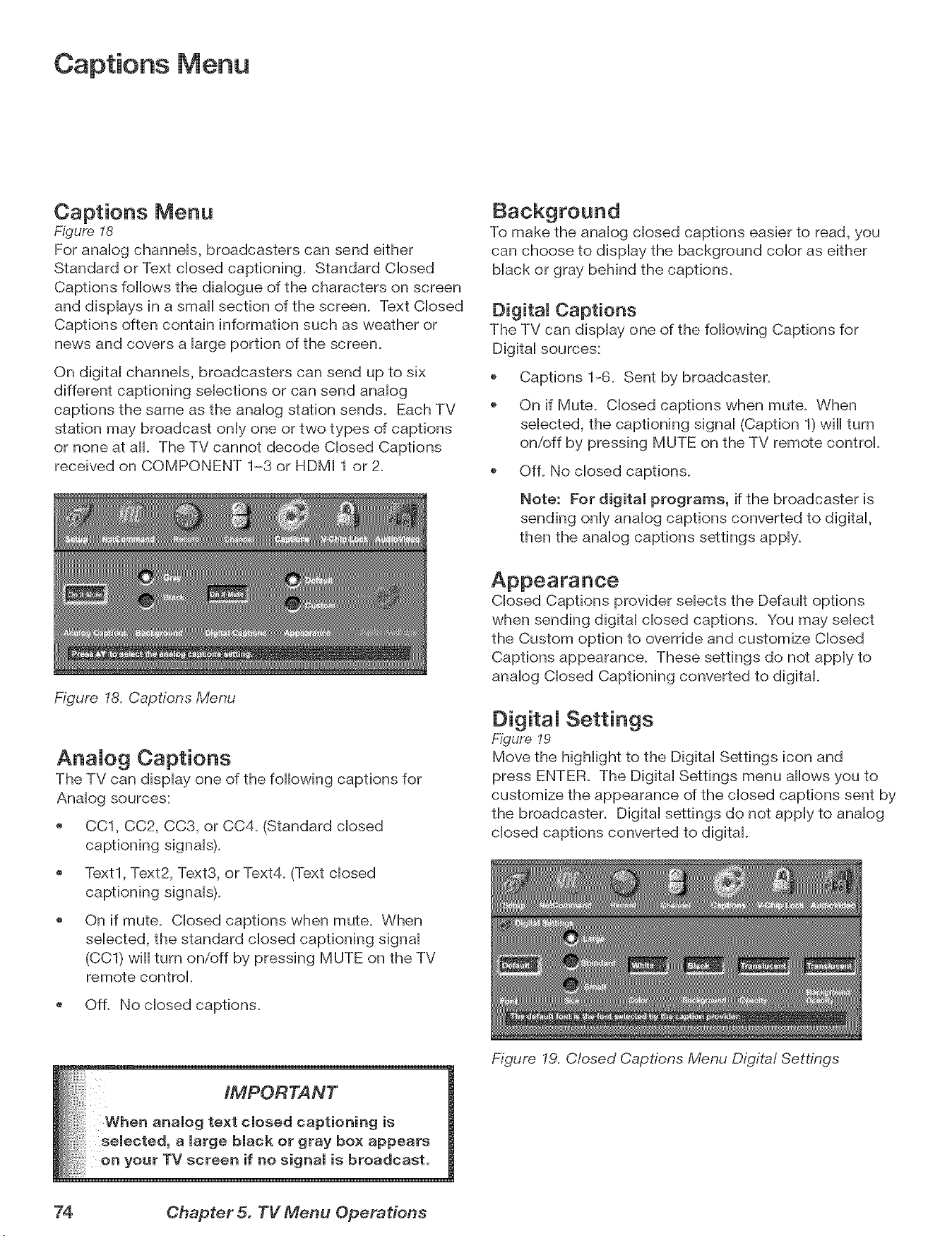
Captions Menu
Captions Menu
Figure 18
For anaHog channeHs, broadcasters can send either
Standard or Text dosed captioning. Standard CHosed
Captions follows the diaHogue of the characters on screen
and dispHays in a small section of the screen. Text CHosed
Captions often contain information such as weather or
news and covers a Hargeportion of the screen.
On digitaH channeHs, broadcasters can send up to six
different captioning seHecfions or can send anaHog
captions the same as the anaHog station sends. Each TV
station may broadcast onHyone or two types of captions
or none at aH. The TV cannot decode CHosed Captions
received on COMPONENT 1-3 or HDMI 1 or 2_
To make the anaHog dosed captions easier to read, you
can choose to dispHay the background coHor as either
black or gray behind the captions.
DigitaJ Captions
The TV can display one of the following Captions for
Digital sources:
@
@
Captions 1-6. Sent by broadcaster.
On if Mute. Closed captions when mute. When
selected, the captioning signal (Caption 1) will turn
on/off by pressing MUTE on the TV remote control.
OfL No closed captions.
Note: For digital programs, if the broadcaster is
sending only analog captions converted to digital,
then the analog captions settings apply.
Figure 18. Captions Menu
AnaJog Captions
The TV can display one of the following captions for
Analog sources:
CC1, CC2, CC3, or CC4_ (Standard closed
captioning signals).
Text1, Text2, Text3, or Text4. (Text closed
captioning signals).
On if mute. Closed captions when mute. When
selected, the standard closed captioning signal
(CC1) will turn on/off by pressing MUTE on the TV
remote control.
Of L No closed captions.
Closed Captions provider selects the Default options
when sending digital closed captions. You may select
the Custom option to override and customize Closed
Captions appearance. These settings do not apply to
analog Closed Captioning converted to digital.
DigitaJ Settings
Figure 19
Move the highlight to the Digital Settings icon and
press ENTER. The Digital Settings menu allows you to
customize the appearance of the closed captions sent by
the broadcaster. Digital settings do not apply to analog
closed captions converted to digital.
__ack or gray box appears
selected, a large black or gray box appears
on your TV screen if no signal is broadcast.
Figure 19. Closed Captions Menu Digital Settings
74 Chapter 5. TV Menu Operations
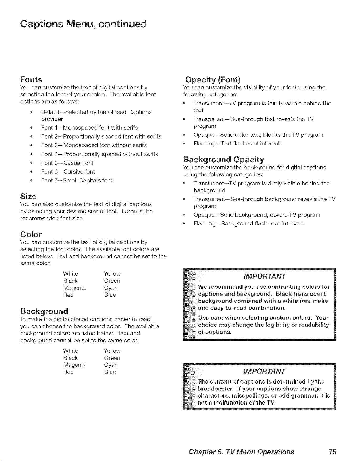
Captions Menu, continued
Fonts
You can customize the text of digitai captions by
sebcfing the font of your choice. The avaiiabb font
options are as foflows:
Defauit--Sebcted by the Cbsed Captions
provider
Font 1--Monospaced font with serifs
Font 2--Proportionally spaced font with serifs
Font 3--Monospaced font without serifs
Font 4--Proportionally spaced without serifs
Font 5--Casuai font
Font 6--Cursive font
Font 7--Small Capitais font
Size
You can abo customize the text of digitai captions
by sebcfing your desired size of font. Large is the
recommended font size.
CoJor
You can customize the text of digital captions by
selecting the font color. The available font colors are
listed below. Text and background cannot be set to the
same color.
White Yellow
Black Green
Magenta Cyan
Red Blue
To make the digital closed captions easier to read,
you can choose the background color. The available
background colors are listed below. Text and
background cannot be set to the same color.
White Yellow
Black Green
Magenta Cyan
Red Blue
You can customize the visibility of your fonts using the
following categories:
Translucent--TV program is faintly visible behind the
text
Transparent--See-through text reveals the TV
program
Opaque--Solid color text; blocks the TV program
Flashing--Text flashes at intervals
Background Opacity
You can customize the background for digital captions
using the following categories:
Translucent--TV program is dimly visible behind the
background
Transparent--See-through background reveals the TV
program
Opaque--Solid background; covers TV program
Flashing--Background flashes at intervals
iMPORTANT
We recommend you use contrasting colors for
background. Black translucent
round combined with a white font make
easy-to-read combination,
Use care when selecting custom colors. Your
choice may change the legibility or readability
of captions,
Chapter 5. TV Menu Operations 75
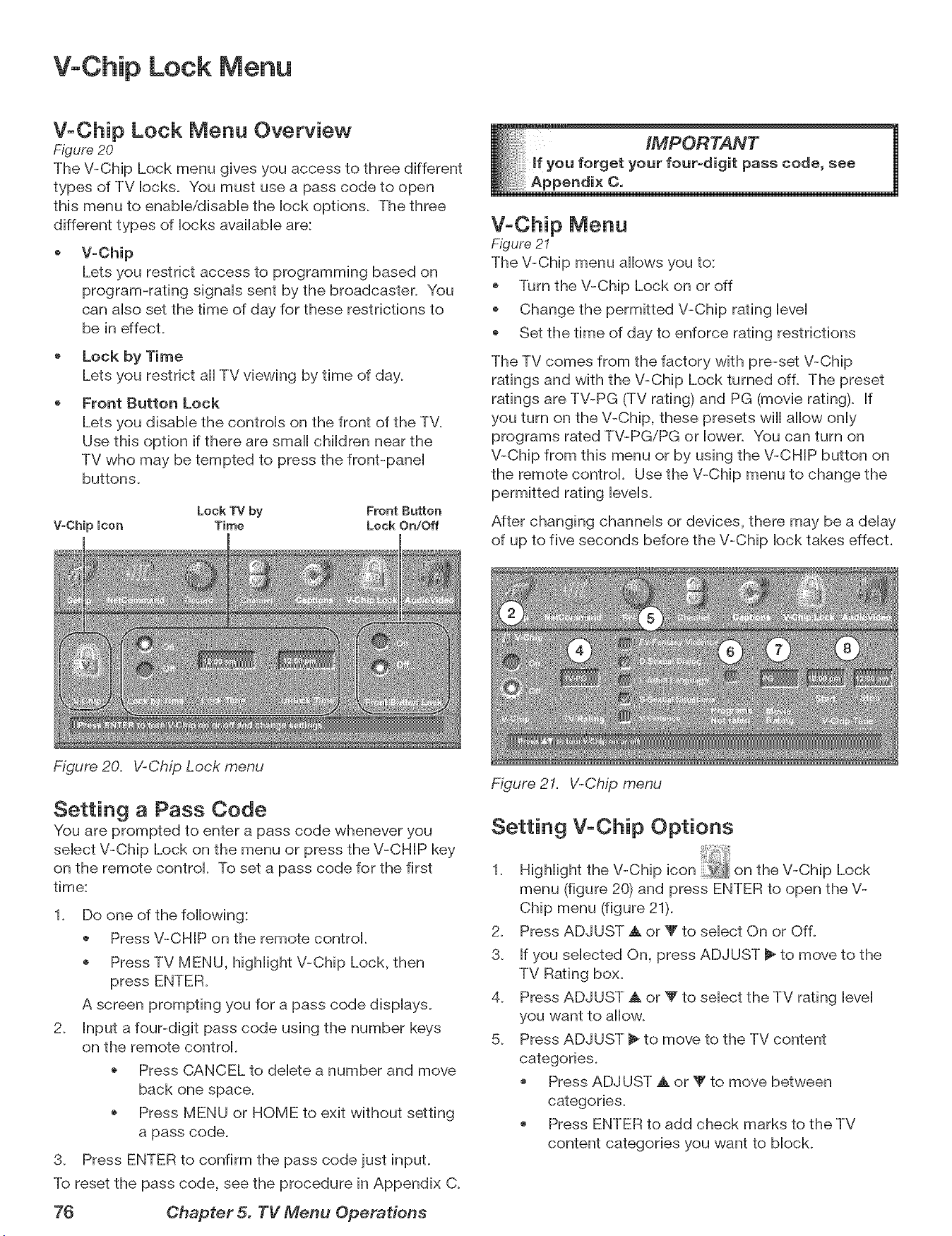
V-Chip Lock Menu
V-Chip Lock Menu Overview
Figure 20
The V-Chip Lock menu gives you access to three different
types of TV locks. You must use a pass code to open
this menu to enabb/disabb the lock options. The three
different types of locks availabb are:
V-Chip
Lets you restrict access to programming based on
program-rating signals sent by the broadcaster. You
can also set the time of day for these restrictions to
be in effect.
Lock by Time
Lets you restrict all TV viewing by time of day.
Front Button Lock
Lets you disabb the controls on the front of the TV.
Use this option if there are small children near the
TV who may be tempted to press the front-panel
buttons.
Lock TV by Front Button
V-Chip Icon Time Lock On/Off
Figure 20. V-Chip Lock ,menu
IMPORTANT 1
u forget your four-digit pass code, see
V-Chip Menu
Figure 21
The V-Chip menu allows you to:
Turn the V-Chip Lock on or off
Change the permitted V-Chip rating bvel
Set the time of day to enforce rating restrictions
The TV comes from the factory with pre-set V-Chip
ratings and with the V-Chip Lock turned off. The preset
ratings are TV-PG (TV rating) and PG (movie rating). If
you turn on the V-Chip, these presets will allow only
programs rated TV-PG/PG or lower. You can turn on
V-Chip from this menu or by using the V-CHIP button on
the remote control. Use the V-Chip menu to change the
permitted rating levels.
After changing channels or devices, there may be a delay
of up to five seconds before the V-Chip lock takes effect.
Setting a Pass Code
You are prompted to enter a pass code whenever you
select V-Chip Lock on the menu or press the V-CHIP key
on the remote control. To set a pass code for the first
time:
1. Do one of the following:
Press V-CHIP on the remote control.
Press TV MENU, highlight V-Chip Lock, then
A screen prompting you for a pass code displays.
2. Input a four-digit pass code using the number keys
on the remote control.
o Press CANCEL to delete a number and move
back one space.
Press MENU or HOME to exit without setting
a pass code.
3. Press ENTER to confirm the pass code just input.
To reset the pass code, see the procedure in Appendix C.
76 Chapter 5. TV Menu Operations
Figure 21. V-Chip ,menu
Setting V-Chip Options
1. Highlight the V-Chip on the V-Chip Lock
menu (figure 20) and press ENTER to open the V-
Chip menu (figure 21).
2. Press ADJUST A or V to select On or Off.
3. If you selected On, press ADJUST _ to move to the
TV Rating box.
4. Press ADJUST A or V to select the TV rating level
you want to aiiow.
5. Press ADJUST _ to move to the TV content
categories.
o Press ADJUST A or V to move between
categories.
Press ENTER to add check marks to the TV
content categories you want to block.
V+Chip Lock Menu, continued
6.
Press ADJUST _ to move to the Programs Not Rated
box. Press ENTER to add or delete a check mark to
allow or block programs that are not rated.
NOTE: Use care when choosing to block unrated
programming. News programs and emergency
bulletins carry the '+None" or "NR" (Not Rated) V-Chip
rating, and these are blocked with this option active.
7. Press ADJUST _ to move to the Movie Rating box.
Press ADJUST _&or V to select the movie rating level
you want to allow+ See the next page for detailed
information on rating guidelines.
8+ To set the time of day when these restrictions will be
in effect, press ADJUST _ to move to the Start box+
To set the time:
a+ With the highlight on the hour number, press
ADJUST _. or _" repeatedly to change the hour+
You can also just press and hold to change the
hour+
b+ Press ENTER to move the highlight to the
minutes+
c+ With the highlight on the minutes number, press
ADJUST a, or V repeatedly to change the
minutes+ Just press and hold to move quickly
through the numbers+
d+ Press ENTER to move the highlight to the am/
pm option+ Press ADJUST A or T to make a
selection+
9+ Press TV MENU to save the settings and close the
menu+
NOTE: To make the V-Chip restrictions active twenty-
four hours a day, set the V-Chip Start and Stop to the
same time+
The V-CHIP Button
Press the V-CHIP button on the remote controi to turn the
V-Chip lock on and off without going through the menu+
A screen wiii appear prompting you for your pass code+
To change V-Chip settings, you must open the V-Chip
Lock Menu and then open the V-Chip menu+
Lock by Time
Lock by Time allows you to entireiy biock use of the TV
during specified hours. During the lock time, you must
use your pass code to view the TV+ To lock the TV by
time:
1+ Press ADJUST a, or V to select On or Off for Lock by
Time.
2+ Press ADJUST _ to move to the Lock Time box.
a+ With the higMight on the hour number, press
ADJUST _. or Y repeatedly to change the hour+
You can also just press and hold to change the
hour.
b. Press ENTER to move the highlight to the
minutes+
c+ With the highlight on the minutes number, press
ADJUST A or _' repeatedly to change the
minutes+ Just press and hold to move quickly
through the numbers+
d+ Press ENTER to move the highlight to the am/
pm option+ Press ADJUST A or Y to make a
selection+
To make Lock by Time active 24 hours a day, set the Lock
and Unlock Times to the same time+
Front Button Lock
Figure 20
Front Button Lock lets you disable controls on the front
panel to prevent inadvertent changes to TV settings.
Select On to disable the buttons and select Off to restore
their operation.
To disable the front button lock, press and hold the
MENU button on the front panel for more than eight
seconds. If the TV is on, a message will display
confirming release of the Front Button Lock.
Bypassing V-Chip Lock and Lock by
If you try to watch blocked programming, a notice
appears prompting you for a pass code+ To use the TV:
+ Input your four-digit pass code and press ENTER+
+ Change to a channel airing an allowed program or
change to another device+
If you try to use the TV when it is locked by time, a
similar screen appears, prompting you for your pass
code+
To reactivate the V-Chip lock or TV lock by time after
using the pass code, power the TV off and then on+
Chapter 5. TV Menu Operations 77
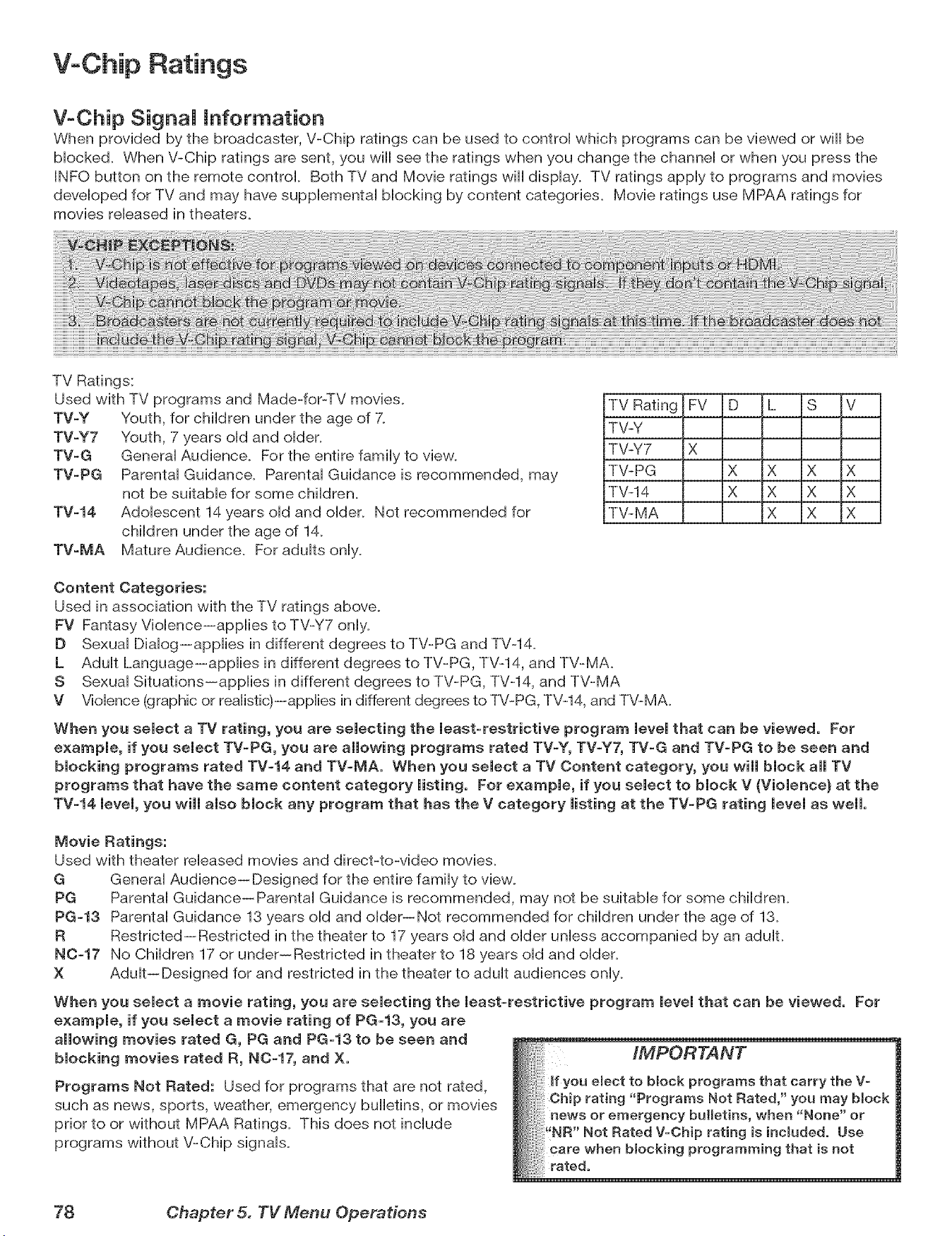
V-Chip Ratings
V-Chip SignaJ Information
When provided by the broadcaster, V-Chip ratings can be used to control which programs can be viewed or will be
Mocked. When V-Chip ratings are sent, you will see the ratings when you change the channeH or when you press the
INFO button on the remote control Both TV and Movie ratings will dispHay. TV ratings appHyto programs and movies
deveHoped for TV and may have supplemental blocking by content categories. Movie ratings use MPAA ratings for
movies released in theaters.
TV Ratings:
Used with TV programs and Made-for-TV movies.
TV-Y Youth, for chiHdren under the age of 7.
TV-Y7 Youth, 7 years oHdand oHder.
TV-G GeneraH Audience. For the entire family to view.
TV-PG Parental Guidance. Parental Guidance is recommended, may
not be suitable for some children.
TV-14 Adolescent 14 years old and older. Not recommended for
children under the age of 14.
TV-MA Mature Audience. For adults only.
TV Rating FV D L S V
TV-Y
TV-Y7 X
TV-PG X X X X
TV-14 X X X X
TV-MA X X X
Content Categories:
Used in association with the TV ratings above.
FV Fantasy Violence--applies to TV-Y7 only.
D Sexual Dialog--applies in different degrees to TV-PG and TV-14.
L Adult Language--applies in different degrees to TV-PG, TV-14, and TV-MA.
S Sexual Situations--applies in different degrees to TV-PG, TV-14, and TV-MA
V Violence (graphic or realistic)--applies in different degrees to TV-PG, TV-14, and TV-MA.
When you select a TV rating, you are selecting the least-restrictive program level that can be viewed. For
example, if you select TV=PG, you are allowing programs rated TV-Y, TV-Y7, TV=G and TV-PG to be seen and
blocking programs rated TV=14 and TV-MA, When you select a TV Content category, you will block all TV
programs that have the same content category listing, For example, if you select to block V (Violence} at the
TV-14 level, you will also block any program that has the V category misting at the TV-PG rating level as well.
Movie Ratings:
Used with theater released movies and direct-to-video movies.
G General Audience-- Designed for the entire family to view_
PG Parental Guidance--Parental Guidance is recommended, may not be suitable for some children_
PG-13 Parental Guidance 13 years old and older--Not recommended for children under the age of 13_
R Restricted--Restricted in the theater to 17 years old and older unless accompanied by an adulL
N0-17 No Children 17 or under--Restricted in theater to 18 years old and older_
X Adult--Designed for and restricted in the theater to adult audiences only.
When you select a movie rating, you are selecting the least=restrictive program level that can be viewed, For
example, if you select a movie rating of PG-13, you are
allowing movies rated G, PG and PG-13 to be seen and
blocking movies rated R, N0=17, and X.
Programs Not Rated: Used for programs that are not rated,
such as news, sports, weather, emergency bulletins, or movies
prior to or without MPAA Ratings. This does not include
programs without V-Chip signals.
__ted, ' you may bBock
78 Chapter 5. TV Menu Operations
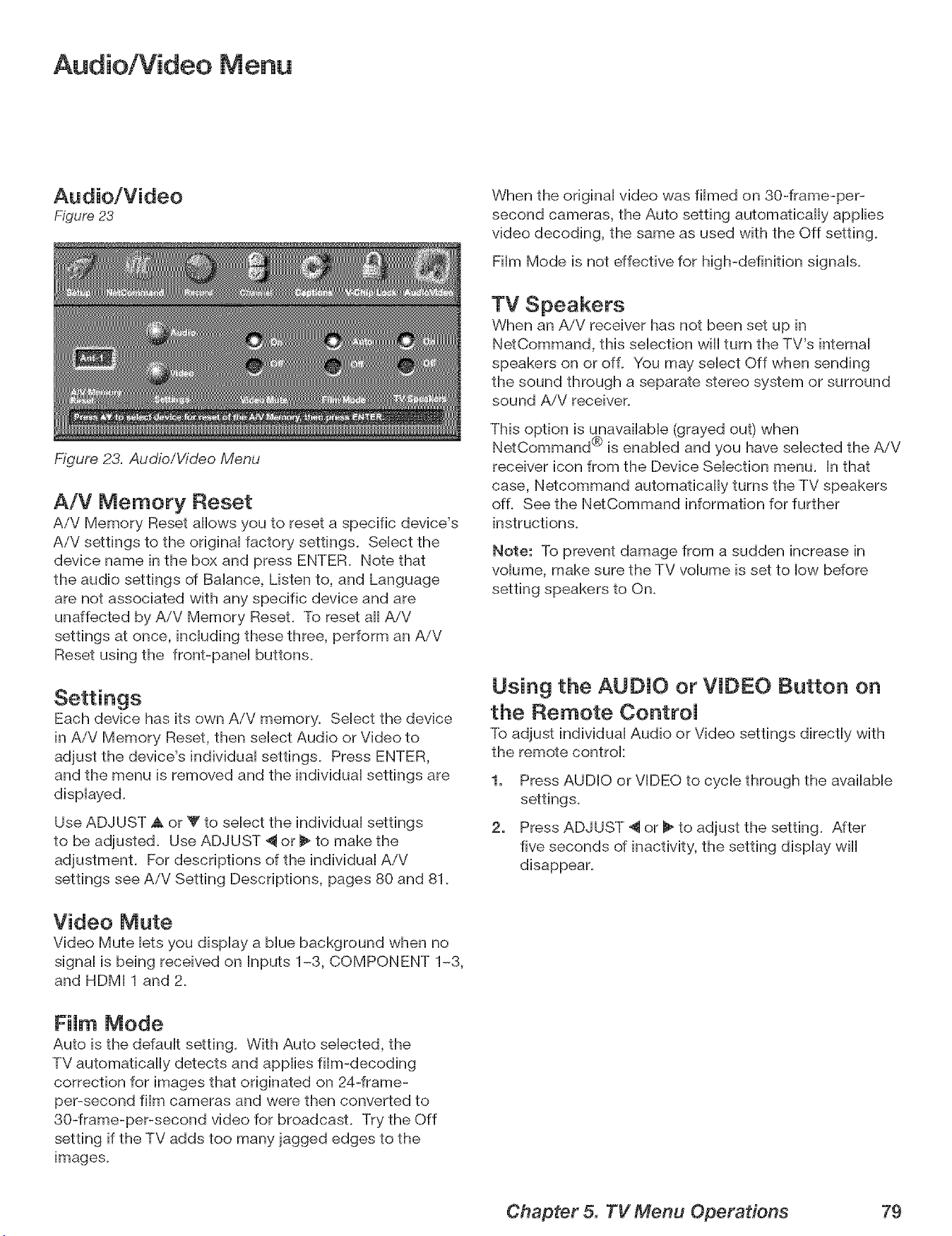
Audio/Video Menu
Figure 23
Figure 23. Audio/Video Menu
A/V Memory Reset
AiV Memory Reset allows you to reset a specific device's
AiV settings to the originaH factory settings. SeHectthe
device name in the box and press ENTER. Note that
the audio settings of BaHance, Listen to, and Language
are not associated with any specific device and are
unaffected by A/V Memory Reset. To reset aH AiV
settings at once, incHuding these three, perform an AiV
Reset using the front-paneH buttons.
Settings
Each device has its own AiV memory. SeHect the device
in AiV Memory Reset, then seHect Audio or Video to
adjust the device's individuaH settings. Press ENTER,
and the menu is removed and the individual settings are
displayed.
Use ADJUST Akor Y to select the individual settings
to be adjusted. Use ADJUST _ or _ to make the
adjustment. For descriptions of the individual AiV
settings see AiV Setting Descriptions, pages 80 and 81.
Video Mute
Video Mute lets you display a blue background when no
signal is being received on Inputs 1-3, COMPONENT 1-3,
and HDMI 1 and 2.
FiJm Mode
Auto is the default setting. With Auto selected, the
TV automatically detects and applies film-decoding
correction for images that originated on 24-frame-
per-second film cameras and were then converted to
30-frame-per-second video for broadcast. Try the Off
setting if the TV adds too many jagged edges to the
images.
When the original video was filmed on 30-frame-per-
second cameras, the Auto setting automatically applies
video decoding, the same as used with the Off setting.
Film Mode is not effective for high-definition signals.
TV Speakers
When an AiV receiver has not been set up in
NetCommand, this selection will turn the TV's internal
speakers on or off. You may select Off when sending
the sound through a separate stereo system or surround
sound AiV receiver.
This option is unavailable (grayed out) when
®
NetCommand is enabled and you have selected the AiV
receiver icon from the Device Selection menu. In that
case, Netcommand automatically turns the TV speakers
off. See the NetCommand information for further
instructions.
Note: To prevent damage from a sudden increase in
volume, make sure the TV volume is set to low before
setting speakers to On.
Using the AUDIO or VIDEO Button on
the Remote ControJ
To adjust individual Audio or Video settings directly with
the remote controk
1. Press AUDIO or VIDEO to cycle through the available
settings.
2. Press ADJUST 4 or _ to adjust the setting. After
five seconds of inactivity, the setting display will
disappear.
Chapter 5. TV Menu Operations 79
Audio Settings
q
NOTE: The effects of the audio settings of Bass, Trebb, Baiance and Surround affect the sound heard through the /
TV speakers oniy.
/
AnaJog and DigitaJ Audio Settings
A siider dispiays on screen for most settings. When the
siider is dispiayed, it has a numeric vaiue, so that 63 is
the maximum, 31 is the mid-point, and 0 is the minimum.
0 Bass
Enhances or reduces How-pitched sound.
0 Treble
Enhances or reduces high-pitched sound.
0 Balance
Adjusts the ievei of sound between the Heftand right
speakers.
0 Surround
Creates simuiated stereo and surround effects
through the TV speakers. Your choices are:
Off: No surround effects.
Simubted Stereo: Your TV will create a simuiated
stereo effect when watching a non-stereo
program.
Surround Sound: Your TV will create a simubted
surround effect when watching a stereo program.
0 Level Sound
Turn On or Off to automatically equalize the
volume level when there are significant soundqevel
differences between program segments, e.g.,
between regular programming and commercials. To
receive the best fidelity with music programs, turn
this setting to Off. When connecting to an AiV
receiver, set level sound to OFF and turn the TV
speakers off to send full dynamics to the AiV receiver.
AnaJog-OnJy Audio Settings
You can set analog-only audio settings while viewing
either analog or digital sources, but the settings affect
broadcast or recorded analog content.
0 Listen to
Determines how your TV receives a broadcast audio
signal and plays the sound you hear.
Your choices are:
Stereo: Default setting. The TV plays stereo
broadcasts in stereo and mono broadcasts in
mono. The word "Stereo" is displayed when you
tune to a channel broadcasting in stereo.
SAP (Second Audio Program): Additional
monaural sound track that you cannot hear
during normal TV viewing. The SAP signal might
be related to the program you are watching,
(such as a sound track in a foreign language), or
it might be unrelated (such as a weather report).
If an SAP signal is broadcast, the letters "SAP"
are displayed when you tune to the channel.
Mono: Reduces background noise. Use when
receiving a weak stereo audio signal. All audio is
played mono with this setting.
Listen to is not available for devices connected to the TV
Inputs, component inputs, or 1394 devices.
DigitaJ-Orfly Audio Settings
You can set digitaPonly audio settings while viewing
either analog or digital sources, but the settings affect
only broadcast or recorded digital content.
0 Language
Determines what possible language you can hear.
Your choices are:
French
German
Italian
Portuguese
Spanish
Other
IEEE 1394 AmpJifier Settings
0 Balance
Adjusts the level of sound between the left and right
speakers. The slider range is 0-254, with 127 at the
center.
0 Loudness
Set to On to make the audio level more uniform.
0 Preset
Select the mode that matches the audio source.
Your choices are:
Off _ Classical Music
Jazz _ Movie
Rock _ Speech
Equalize the sound.
80 Chapter 5. TV Menu Operations
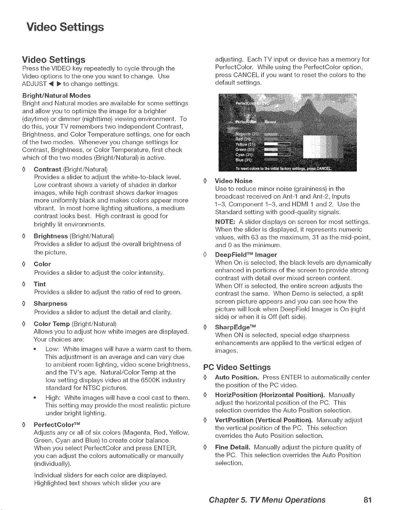
Video Settings
Video Settings
Press the VIDEO key repeatedly to cycle through the
Video options to the one you want to change. Use
ADJUST 4 _ to change settings.
Bright/Natural Modes
Bright and Natural modes are available for some settings
and allow you to optimize the image for a brighter
(daytime) or dimmer (nighttime) viewing environment. To
do this, your TV remembers two independent Contrast,
Brightness, and Color Temperature settings, one for each
of the two modes. Whenever you change settings for
Contrast, Brightness, or Color Temperature, first check
which of the two modes (Bright/Natural) is active.
Contrast (Bright/Natural)
Provides a slider to adjust the white-to-black level.
Low contrast shows a variety of shades in darker
images, while high contrast shows darker images
more uniformly black and makes colors appear more
vibrant. In most home lighting situations, a medium
contrast looks best. High contrast is good for
brightly lit environments.
Brightness (Bright/Natural)
Provides a slider to adjust the overall brightness of
the picture.
O Color
Provides a slider to adjust the color intensity.
O Tint
Provides a slider to adjust the ratio of red to green.
0 Sharpness
Provides a slider to adjust the detail and clarity.
0 Color Temp (Bright/Natural)
Allows you to adjust how white images are displayed.
Your choices are:
Low: White images will have a warm cast to them.
This adjustment is an average and can vary due
to ambient room lighting, video scene brightness,
and the TV's age. Natural/Color Temp at the
low setting displays video at the 6500K industry
standard for NTSC pictures.
High: White images will have a cool cast to them.
This setting may provide the most realistic picture
under bright lighting.
PerfectOolor TM
Adjusts any or all of six colors (Magenta, Red, Yellow,
Green, Cyan and Blue) to create color balance.
When you select PerfectColor and press ENTER,
you can adjust the colors automatically or manually
(individually).
Individual sliders for each color are displayed.
Highlighted text shows which slider you are
adjusting. Each TV input or device has a memory for
PerfectColor. While using the PerfectColor option,
press CANCEL if you want to reset the colors to the
0 Video Noise
Use to reduce minor noise (graininess) in the
broadcast received on Ant-1 and Ant-2, Inputs
1-3, Component 1-3, and HDMI 1 and 2. Use the
Standard setting with good-quality signals.
NOTE: A slider displays on screen for most settings.
When the slider is displayed, it represents numeric
values, with 63 as the maximum, 31 as the mid-point,
and 0 as the minimum.
§ DeepField TM Imager
When On is selected, the black levels are dynamically
enhanced in portions of the screen to provide strong
contrast with detail over mixed screen content.
When Off is selected, the entire screen adjusts the
contrast the same. When Demo is selected, a split
screen picture appears and you can see how the
picture will look when DeepField Imager is On (right
side) or when it is Off (left side).
0 SharpEdge TM
When ON is selected, special edge sharpness
enhancements are applied to the vertical edges of
images.
PC Video Settings
0 Auto Position. Press ENTER to automatically center
the position of the PC video.
0 HorizPosition (Horizontal Position}, Manually
adjust the horizontal position of the PC. This
selection overrides the Auto Position selection.
0 VertPosition (Vertical Position}, Manually adjust
the vertical position of the PC. This selection
overrides the Auto Position selection.
0 Fine Detail. Manually adjust the picture quality of
the PC. This selection overrides the Auto Position
selection.
Chapter 5. TV Menu Operations 81

Add I Features
MediaCommand TM and Memory Card Playback .............. 84
Operation of PIP and POP ............................. 86
TV DispUay Formats .................................. 87
PC Viewing ....................................... 89
PC DispJay Formats ................................. 90
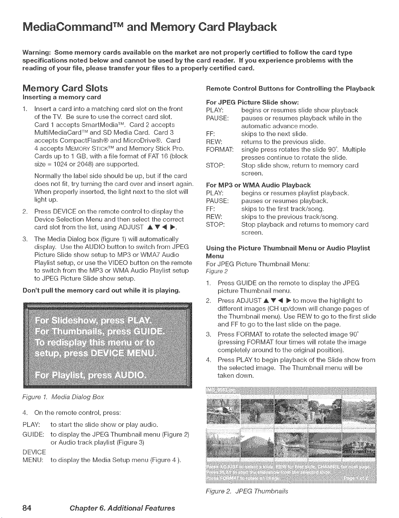
MediaCommand TM and Memory Card Playback
Warning: Some memory cards available on the market are not properly certified to follow the card type
specifications noted below and cannot be used by the card reader, if you experience problems with the
reading of your file, please transfer your files to a properly certified card.
Memory Card SJots
inserting a memory card
1_ Insert a card into a matching card slot on the front
of the TV. Be sure to use the correct card slot.
Card 1 accepts SmartMedia TM. Card 2 accepts
MuitiMediaCard TM and SD Media Card. Card 3
accepts CompactFiash® and MbroDnve®. Card
4 accepts MEMORYSTICKTM and Memory Stick Pro.
Cards up to 1 GB, with a fib format of FAT 16 (block
size = 1024 or 2048) are supported.
Normally the label side should be up, but if the card
does not fit, try turning the card over and insert again.
When properly inserted, the light next to the slot will
light up.
2. Press DEVICE on the remote control to display the
Device Selection Menu and then select the correct
card slot from the list, using ADJUST ,A V 4 _.
3_
The Media Dialog box (figure 1) will automatically
display. Use the AUDIO button to switch from JPEG
Picture Slide show setup to MP3 or WMA7 Audio
Haylist setup, or use the VIDEO button on the remote
to switch from the MP3 or WMA Audio Haylist setup
to JPEG Picture Slide show setup.
Don't pull the memory card out while it is playing.
Remote Control Buttons for Controlling the Pmayback
For JPEG Picture Slide show:
PLAY: begins or resumes slide show playback
PAUSE: pauses or resumes playback while in the
automatic advance mode.
FF: skips to the next slide.
REW: returns to the previous slide_
FORMAT: single press rotates the slide 90°_ Multiple
presses continue to rotate the slide.
STOP: Stop slide show, return to memory card
screen_
For MP3 or
PLAY:
PAUSE:
FF:
REW:
STOP:
WMA Audio Playback
begins or resumes playlist playback.
pauses or resumes playback.
skips to the first track/song.
skips to the previous track/song.
Stop playback and returns to memory card
screen_
Using the Picture Thumbnail Menu or Audio Playlist
Menu
For JPEG Picture Thumbnail Menu:
Figure 2
1_ Press GUIDE on the remote to display the JPEG
picture Thumbnail menu.
2_ Press ADJUST _k V _ _ to move the highlight to
different images (CH up/down will change pages of
the Thumbnail menu). Use REW to go to the first slide
and FF to go to the last slide on the page.
3_ Press FORMAT to rotate the selected image 90 °
(pressing FORMAT four times will rotate the image
completely around to the original position).
4. Press PLAY to begin playback of the Slide show from
the selected image. The Thumbnail menu will be
taken down.
Figure I. Media Dialog Box
4_
PLAY:
GUIDE:
On the remote control, press:
to start the slide show or play audio.
to display the JPEG Thumbnail menu (Figure 2)
or Audio track piayiist (Figure 3)
DEVICE
MENU:
to display the Media Setup menu (Figure 4 ).
} }
Figure 2. JPEG Thumbnails
84 Chapter 6. Additional Features
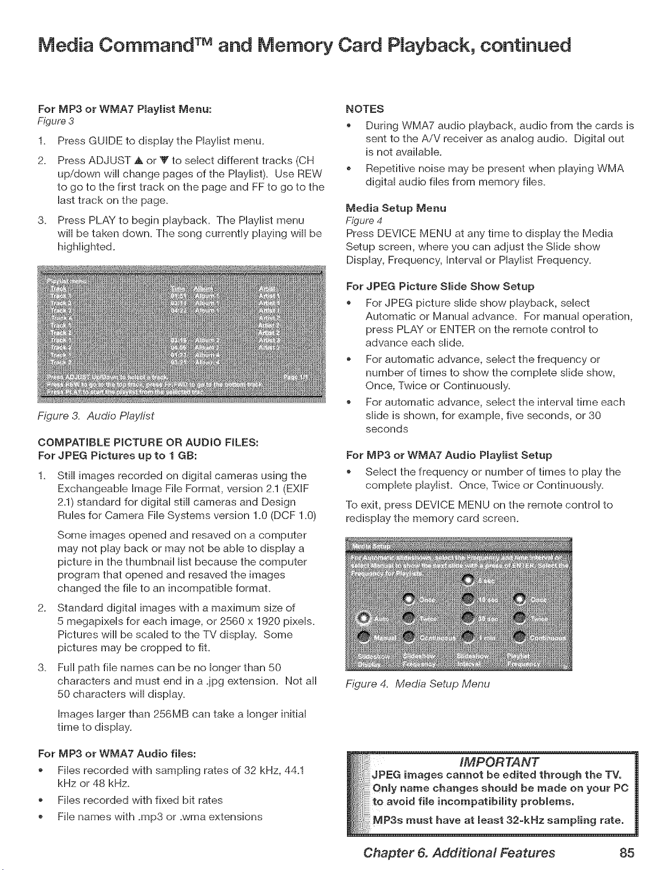
Media Command TM and Memory Card Playback, continued
For MP3 or WMA7 Piayiist Menu:
Figure 3
2_
Press GUIDE to dispHay the PHayHistmenu.
Press ADJUST & or V to seHectdifferent tracks (CH
up/down will change pages of the PHayHist).Use REW
to go to the first track on the page and FF to go to the
Hasttrack on the page.
3. Press PLAY to begin pHayback. The PHayHistmenu
will be taken down. The song currently pHaying will be
Figure 3. Audio P/aylist
COMPATIBLE PICTURE OR AUDIO FILES:
For JPEG Pictures up to 1 GB:
1. Still images recorded on digitaH cameras using the
ExchangeabHe Bmage FiHeFormat, version 2.1 (EXlF
2.1) standard for digital still cameras and Design
Rules for Camera File Systems version 1.0 (DCF 1.0)
Some images opened and resaved on a computer
may not play back or may not be able to display a
picture in the thumbnail list because the computer
program that opened and resaved the images
changed the file to an incompatible format.
2. Standard digital images with a maximum size of
5 megapixels for each image, or 2560 x 1920 pixels.
Pictures will be scaled to the TV display. Some
pictures may be cropped to fit.
3_ Full path file names can be no longer than 50
characters and must end in a jpg extension. Not all
50 characters will display.
Images larger than 256MB can take a longer initial
time to display.
For MP3 or WMA7 Audio files:
Files recorded with sampling rates of 32 kHz, 44_1
kHz or 48 kHz.
Files recorded with fixed bit rates
File names with .mp3 or .wma extensions
NOTES
During WMA7 audio playback, audio from the cards is
sent to the AiV receiver as analog audio. Digital out
is not available.
Repetitive noise may be present when playing WMA
digital audio files from memory files.
Media Setup Menu
Figure 4
Press DEVICE MENU at any time to display the Media
Setup screen, where you can adjust the Slide show
Display, Frequency, Interval or Haylist Frequency_
For JPEG Picture Slide Show Setup
For JPEG picture slide show playback, select
Automatic or Manual advance. For manual operation,
press PLAY or ENTER on the remote control to
advance each slide.
For automatic advance, select the frequency or
number of times to show the complete slide show,
Once, Twice or Continuously.
For automatic advance, select the interval time each
slide is shown, for example, five seconds, or 30
seconds
For MP3 or WMA7 Audio Playlist Setup
Select the frequency or number of times to play the
complete playlist. Once, Twice or Continuously.
To exit, press DEVICE MENU on the remote control to
redisplay the memory card screen.
Figure 4. Media Setup Menu
___hrough the TVo
be o. yourPC
Chapter 6. Additional Features 85
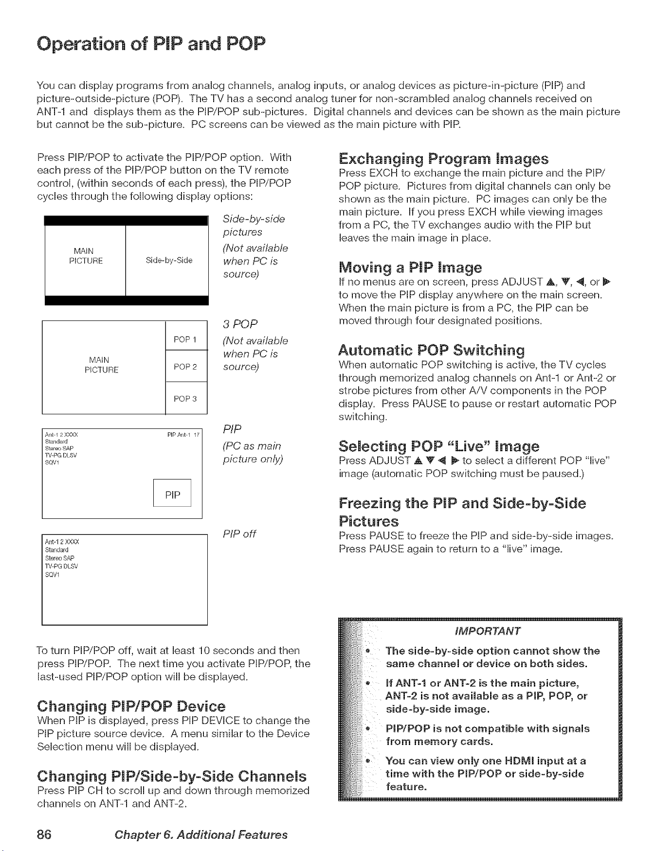
Operation of PIP and POP
You can display programs from analog channeb, analog inputs, or analog devices as pbtureqn-picture (PIP) and
pbture-outside-pbture (POP)+ The TV has a second analog tuner for non-scrambbd analog channels received on
ANT-1 and displays them as the PIP/POP sub-pictures. Digital channeb and devices can be shown as the main picture
but cannot be the sub-pbture. PC screens can be viewed as the main picture with PIR
Press PIP/POP to activate the PIP/POP option. With
each press of the PIP/POP button on the TV remote
control, (within seconds of each press), the PIP/POP
cycbs through the following display options:
MA_N
PICTURE Side-by-Side
Side-by-side
pictures
(Not available
when PC is
source)
MA_N
PICTURE
POP 1
POP 2
POP 3
3 POP
(Not available
when PC is
source)
Ant-I 2 X)OLX
Standard
Stereo SAP
rV-PG DLSV
SQV1
PIP/_qt-l 17
PIP
(PC as main
picture only)
Ant-12 XXXX
Stand_d
Stereo SAP
TV+PG DLSV
SQVl
PIP off
Exchanging Program Images
Press EXCH to exchange the main picture and the PIP/"
POP picture. Pictures from digital channels can only be
shown as the main picture. PC images can only be the
main picture. If you press EXCH while viewing images
from a PC, the TV exchanges audio with the PIP but
leaves the main image in place.
Moving a PIP image
If no menus are on screen, press ADJUST _,, _F,4, or
to move the PIP display anywhere on the main screen.
When the main picture is from a PC, the PIP can be
moved through four designated positions.
Automatic POP Switching
When automatic POP switching is active, the TV cycles
through memorized analog channeb on Ant-1 or Ant-2 or
strobe pictures from other A/V components in the POP
display. Press PAUSE to pause or restart automatic POP
switching.
SeJecting POP "Live" image
Press ADJUST A T 4 _ to select a different POP "live"
image (automatic POP switching must be paused.)
Freezing the PIP and Side-by-Side
Press PAUSE to freeze the PIP and side-by-side images.
Press PAUSE again to return to a "live" image.
To turn PIP/POP off, wait at bast 10 seconds and then
press PIP/POP. The next time you activate PIP/POP, the
last-used PIP/POP option wiii be displayed.
Changing PIP/POP Device
When PIP is displayed, press PIP DEVICE to change the
PIP picture source device. A menu similar to the Device
Selection menu will be displayed.
Changing PIP/Side-by-Side CharmeJs
Press PIP CH to scroll up and down through memorized
channels on ANT-1 and ANT-2.
iMPORTANT
The side=by=side option cannot show the
same channel or device on both sides,
JfANT-1 or ANT-2 is the main picture,
ANT-2 is not available as a PiP, POP, or
side=by=side image.
PiP/POP is not compatible with signals
from memory cards.
You can view only one HDIVil input at a
time with the PIP/POP or side=by=side
feature.
86 Chapter 6. Add#iona/ Features
TV Display Formats
This is a widescreen TV, aiso known as a 16:9 TV. This shape reflects the new types of images avaiiabb from HDTV
and many DVDs. There are still many oider styb narrow-screen images (caNed 4:3 aspect ratio) you win encounter.
WhiNethere win never be a perfect soiution for dispiaying a narrow image on a wide screen, MitsubisM offers severai
dispiay formats from which to choose.
Press FORMAT on the TV remote controi to cycb through
the avaiiabb dispiay formats. The Hast-used format for
each device is used when you return to that device.
Note: Not all formats are available for PJPI
POP. Side-by-Side is only available in Standard
and Expand formats, Three POP is available
in Standard format only. PO formats vary
depending on the PC signal.
DVD Definitions:
Anamorphic (or Enhanced for Wide-Screen TV's):
These DVDs are recorded in a special way to properly
show wide-screen images on 16:9 TV sets in the
Standard format mode. This is the recommended
choice.
Non-Anamorphic (or 4:3, 1:33:1, Letter box or Full
Screen}:
These DVDs are recorded for use with traditional shaped
TVs. They may be full screen (4:3 or 1:33:1) which crops
movies to fit the narrow TV, or Letter boxed, which adds
black top and bottom bars.
This information may or may not be listed on the DVD
case. Some DVDs support both types of recordings.
Signal Definitions
480i Signals: Traditional analog interlaced signals from
or through ANTq and 2, INPUT 1 and 2, COMPONENT 1-3,
and HDMI 1 and 2.
480p Signals: Progressive-scan analog DVD signals on
COMPONENT inputs and HDMI 1 and 2.
720p & 1080i Signals: High-definition analog signals
received through COMPONENT 1-3 and HDMI 1 and 2.
These signals are always 16:9 (widescreen).
SD 4:3: Standard-definition narrow-screen format signals
from digital channels and JEEE 1394 devices.
SD 16:9: Standard-definition widescreen format signals
from digital channels and EEE 1394 devices.
ND: High-definition wide-screen format signals from digital
channels and EEEN394 devices. These signals are always
16:9 (widescreen).
Format Definitions
Standard: This is the fulhscreen format. HDTV signals
use this format. This format is useful for displaying
Anamorphic DVDs that have 1.78:1 or 1.85:1 aspect
ratios. Anamorphic DVDs that have a 2.35:1 aspect ratio
are displayed with black bars at the top and bottom, but
show the entire image correctly. Narrow (4:3) images
are stretched evenly from side to side. Available for all
signals.
Expand: This enlarges the picture to fill the screen,
cropping off some of the image at the top and bottom.
This is useful for reducing the letter box top and bottom
bars of non-anamorphic DVD images. Available for
analog 480i, 480p and digital SD 4:3 signals only.
Zoom: This enlarges the picture, cropping off some
of the image at each side and top and bottom. This is
useful for removing or reducing the black top and bottom
bars on anamorphic DVDs with a 2.35:1 aspect ratio.
Available for analog 480i and 480p and SD 4:3 signals
only.
Stretch: This format stretches a narrow (4:3) image
across the screen; there is less stretch in the center
than at the sides, however. This aiiows the entire narrow
image to be displayed across the screen with less
distortion than is seen in the Standard format. Available
for analog 480i and 480p and SD 4:3 signals only.
Stretch Plus: Similar to stretch mode, but to minimize
distortions on the side, the picture is expanded to
crop off portions of the top and bottom. When no PIP
is displayed, you can press ADJUST up or down to
vertically adjust the position of the picture. Available for
analog 480i and 480p and SD 4:3 signals only.
Narrow: This format displays narrow (4:3) images in their
original shape, and adds stationary black side bars to fill
the screen. Available for 480i, 480p and digital SD 4:3
signals only.
Wide Expand: Enlarges the picture, cropping some of
the image on both sides. This Expand format is useful
to remove or reduce black side bars added to narrow
images that are converted to 16:9 signals for digital
broadcast. Available for analog 1080i, 720p, digital SD
16:9 and digital HD signals.
Chapter 6. Additional Features 87
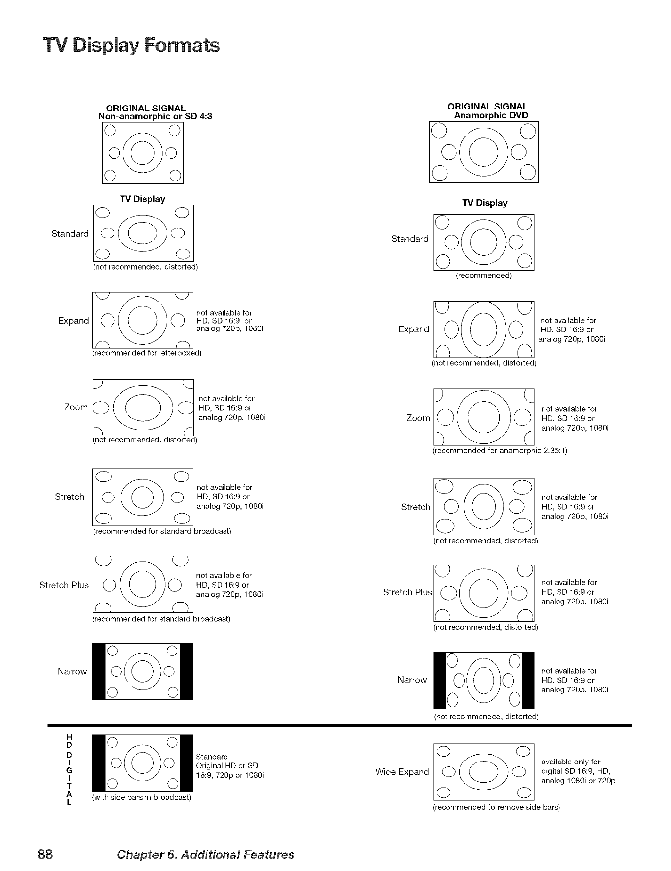
TV Display Formats
ORIGINAL SIGNAL
Non-anamorphic or SD 4:3
Standard
TV Display
(not recommended, distorted)
Expand
_O not available for
HD, SD 16:9 or
analog 720p, 1080i
(recommended for letterboxed)
Zoom
__) _ (_ not available for
HD, SD 16:9 or
analog 720p, 1080i
(not recommended, distorted)
Stretch
notaaia efo
HD, SD 16:9 or
analog 720p, 1080i
(recommended for standard broadcast)
Stretch Plus
_O not available for
HD, SD 16:9 or
analog 720p, 1080i
(recommended for standard broadcast)
Narrow
H
D
D
I
G
I
T
A
L
(with side bars in broadcast)
Standard
Original HD or SD
16:9, 720p or 1O8Oi
Standard
ORIGINAL SIGNAL
Anamorphic DVD
TV Display
(recommended)
__0___(_ not available for
Expand HD, SD 16:9 or
analog 720p, 1080i
(not recommended, distorted)
IO_ O 1 not available for
Zoom HD, SD 16:9 or
analog 720p, 1080i
(recommended for anamorphic 2.35:1)
Stretch
Stretch Plus
Narrow
(not recommended, distorted)
not available for
HD, SD 16:9 or
analog 720p, 1080i
not available for
HD, SD 16:9 or
analog 720p, 1080i
(not recommended, distorted)
Wide Expand
not available for
HD, SD 16:9 or
analog 720p, 1080i
(not recommended, distorted)
(_(_ available only for
digital SD 16:9, HD,
analog 1080i or 720p
(recommended to remove side bars)
88 Chapter 6. Add#ionM Features
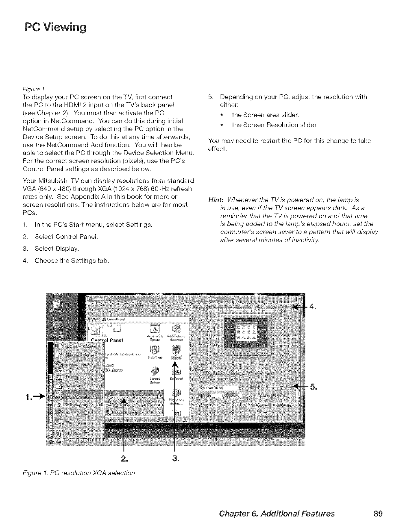
PC Viewing
Figure I
To dispHay your PC screen on the TV, first connect
the PC to the HDMI 2 input on the TV's back paneH
(see Chapter 2). You must then activate the PC
option in NetCommand. You can do this during initiaH
NetCommand setup by seHecting the PC option in the
Device Setup screen. To do this at any time afterwards,
use the NetCommand Add function. You will then be
aMe to seHect the PC through the Device SeHection Menu.
For the correct screen resoHufion (pixeHs),use the PC's
ControH PaneHsettings as described bellow.
Your Mitsubishi TV can dispHay resoHufions from standard
VGA (640 x 480) through XGA (1024 x 768) 60-Hz refresh
rates onHy. See Appendix A in this book for more on
screen resoHutions. The instructions bellow are for most
PCs.
1. In the PC's Start menu, select Settings.
2. Select Control Panel.
3. Select Display.
4. Choose the Settings tab.
5.
Depending on your PC, adjust the resolution with
either:
the Screen area slider.
the Screen Resolution slider
You may need to restart the PC for this change to take
effect.
Hint: Whenever the TV is powered on, the lamp is
in use, even if the TV screen appears dark. As a
reminder that the TV is powered on and that time
is being added to the lamp's elapsed hours, set the
computer's screen saver to a pattern that will display
after several minutes of inactivity.
2_
Figure I. PC resolution XGA selection
3_
Chapter 6. Additional Features 89
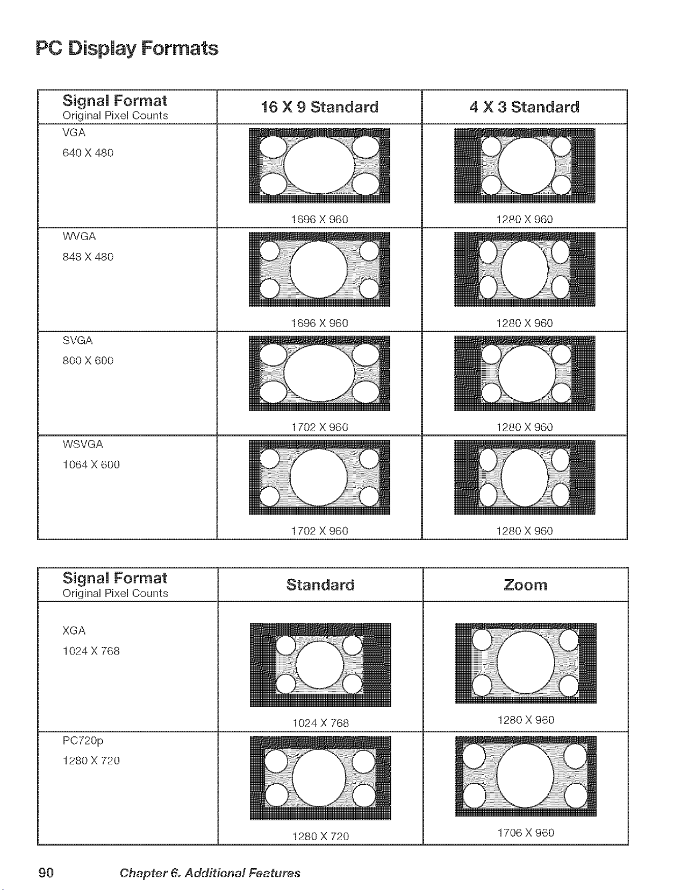
PC Display Formats
_;_u,_,_na,Format 4 X 3 Standard
Original pis4elCounts
VGA
640 X 480
WVGA
848 X 480
SVGA
800 X 600
WSVGA
1064 X 600
16 X 9 Standard
1696 × 960
1696 X 960
1702 X 960
1280 X 960
1280 X 960
1280 X 960
1702 X 960 1280 X 960
Signal Format
Original Pixel Counts
XGA
1024 X 768
PC720p
1280 X 720
1024 X 768
1280 X 720
1280 X 960
1706 X 960
90 Chapter 6. Additional Features
i_ii!_iiii_!_!_',!_ii_!i_!i_,!i_!i_,!i_!i_!i_i!i_i!i_i!i¸i!i_i!i¸i!i_i!i¸i!i_i!i¸i!i_i!i¸i!i_i!i¸i!i_i!i¸i!i_i!i¸i!i_i!i¸i!i_i!i¸i!i_i!i¸i!i_i!i¸i!i_i!i¸i!i_i!i¸i!i_i!i¸i!i_i!i¸i!i_i!i¸i!i_i!i¸i!i_i!i¸i!i_i!i¸i!i_i!i¸i!i_i!i¸i!i_i!i¸i!i_i!i¸i!i_i!i¸i!i_i!i¸i!i_i!i¸i!i_i!i¸i!i_i!i¸i!i_i!i¸i!i_i!i¸i!i_i!i¸i!i_i!i¸i!i_i!i¸i!i_i!i¸i!i_i!i¸i!i_i!i¸i!i_i!i¸i!i_i!i¸i!i_i!i¸i!i_i!i¸i!i_i!i¸i!i_i!i¸i!i_i!i¸i!i_i!i¸i!i_i!i¸i!i_i!i¸i!i_i!i¸i!i_i!i¸i!i_i!i¸i!i_i!i¸i!i_i!i¸i!i_i!i¸i!i_i!i¸i!i_i!i¸i!i_i!i¸i!i_i!i¸i!i_i!i¸i!i_i!i¸i!i_i!i¸i!i_i!i¸i!i_i!i¸i!i_i!i¸i!i_i!i¸i!i_i!i¸i!i_i!i¸i!i_i!i¸i!i_i!i¸i!i_i!i¸i!i_i!i¸i!i_i!i¸i!i_i!i¸i!i_i!i¸i!i_i!i_!_!__,!,
g
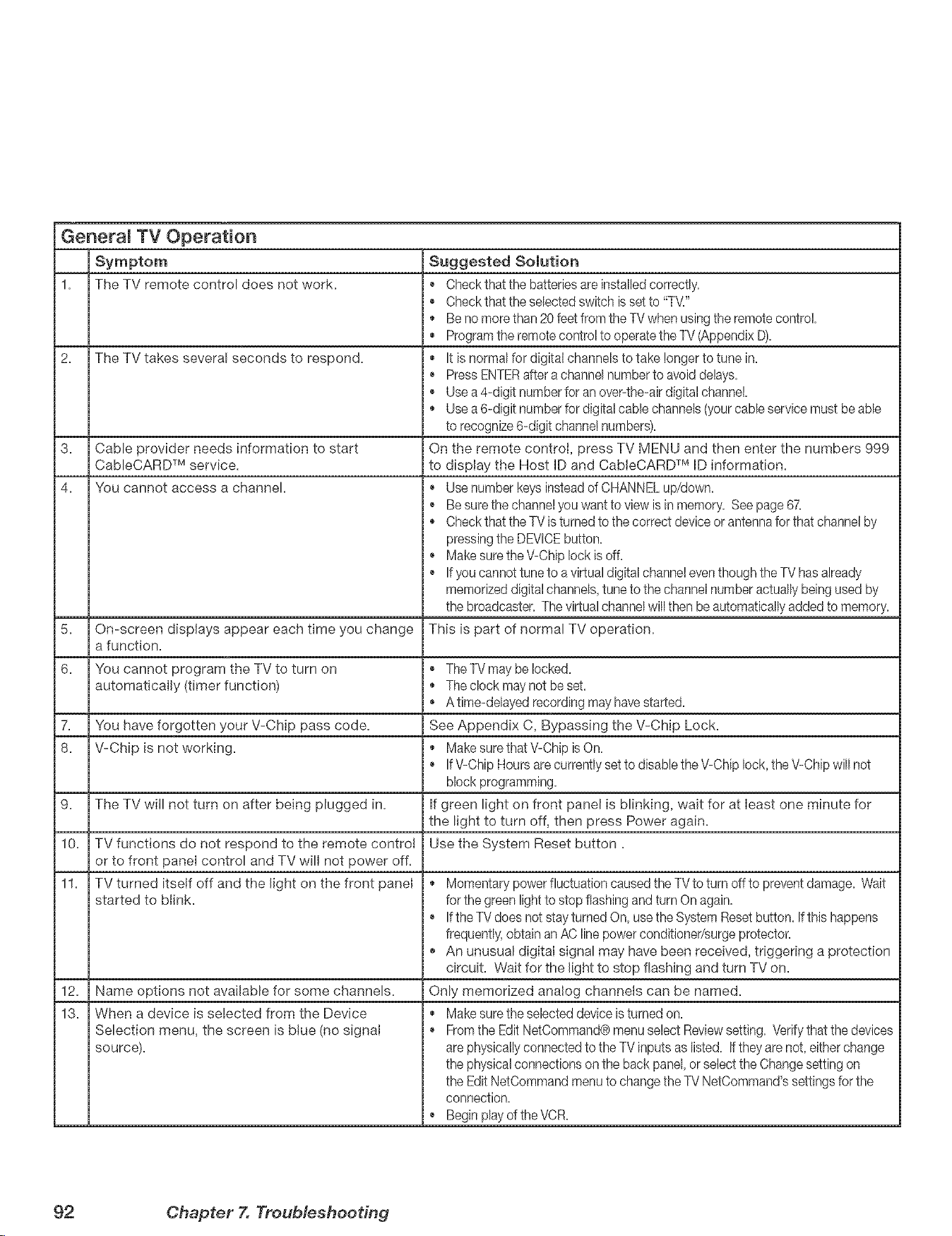
Generam TV Operation
Symptom Suggested Solution
1. The TV remote control does not work. , • Check that the batteries are instalbd correctly.
, • Check that the selected switch is set to "TV/'
,, Be no morethan 20 feet from the TVwhen using the remote control.
, ,, Program the remotecontrol to operatethe TV (,AppendixD).
2. The TV takes several seconds to respond. ,, It is normal for digital channels to take longer to tune in.
, • Press ENTERafter a channel numberto avoiddelays.
, • Use a 4-digit numberfor an over-the-air digital channel.
,, Use a 6-digit number for digital cable channels (your cable service must be able
to recognize 6-digit channel numbers).
3. Cable provider needs information to start On the remote control, press TV MENU and then enter the numbers 999
CableCARD TM service, to display the Host ID and CableCARD TM ID information.
4. You cannot access a channel. • Use number keys insteadof CHANNELup/down.
, • Be sure the channelyou want to view is in memory. See page 67.
,, Check that the TV is turned to the correct device orantenna for that channel by
pressing the DEVICEbutton.
, • Make sure the V-Chip lock is off.
, • If you cannot tune to a virtual digital channel eventhough the TV has already
memorized digital channeb, tune to the channel number actuallybeing used by
the broadcaster. The virtual channel will then be automatically added to memory.
On-screen displays appear each time you change This is part of normal TV operation.
5.
a function.
6. You cannot program the TV to turn on • The TV may be locked.
automatically (timer function) • The clock may not be set.
, • A time-deByed recording may have started.
7. You have forgotten your V-Chip pass code. See Appendix C, Bypassing the V-Chip Lock.
8. V-Chip is not working. ,_ Make sure that V-Chip is On.
If V-Chip Hours are currently set to disable the V-Chip lock, the V-Chip will not
block programming.
9. The TV will not turn on after being plugged in. if green light on front panel is blinking, wait for at bast one minute for
the light to turn off, then press Power again.
10. Use the System Reset button.
11. ,, Momentary power fluctuation caused the TVto turn off to prevent damage. Wait
12.
13.
TV functions do not respond to the remote control
or to front panel control and TV will not power off.
TV turned itself off and the light on the front panel
started to blink.
Name options not available for some channels.
When a device is selected from the Device
Selection menu, the screen is blue (no signal
source).
for the green light to stop flashing and turn On again.
If the TV does not stay turned On, use the System Reset button. If this happens
frequently,obtain an AC line power conditioner/surge protector.
, ,, An unusual digital signal may have been received, triggering a protection
circuit. Wait for the light to stop flashing and turn TV on.
Only memorized analog channels can be named.
, ,, Make sure the selected device is turned on.
From the Edit NetCommand® menu select Reviewsetting. Verifythat the devices
are physically connected to the TV inputs as listed. Ifthey are not, either change
the physical connections on the back panel, or select the Changesetting on
the Edit NetCommand menu to changethe TV NetCommand's settings for the
connection.
, • Begin play of the VCR.
92 Chapter X Troublesheodng
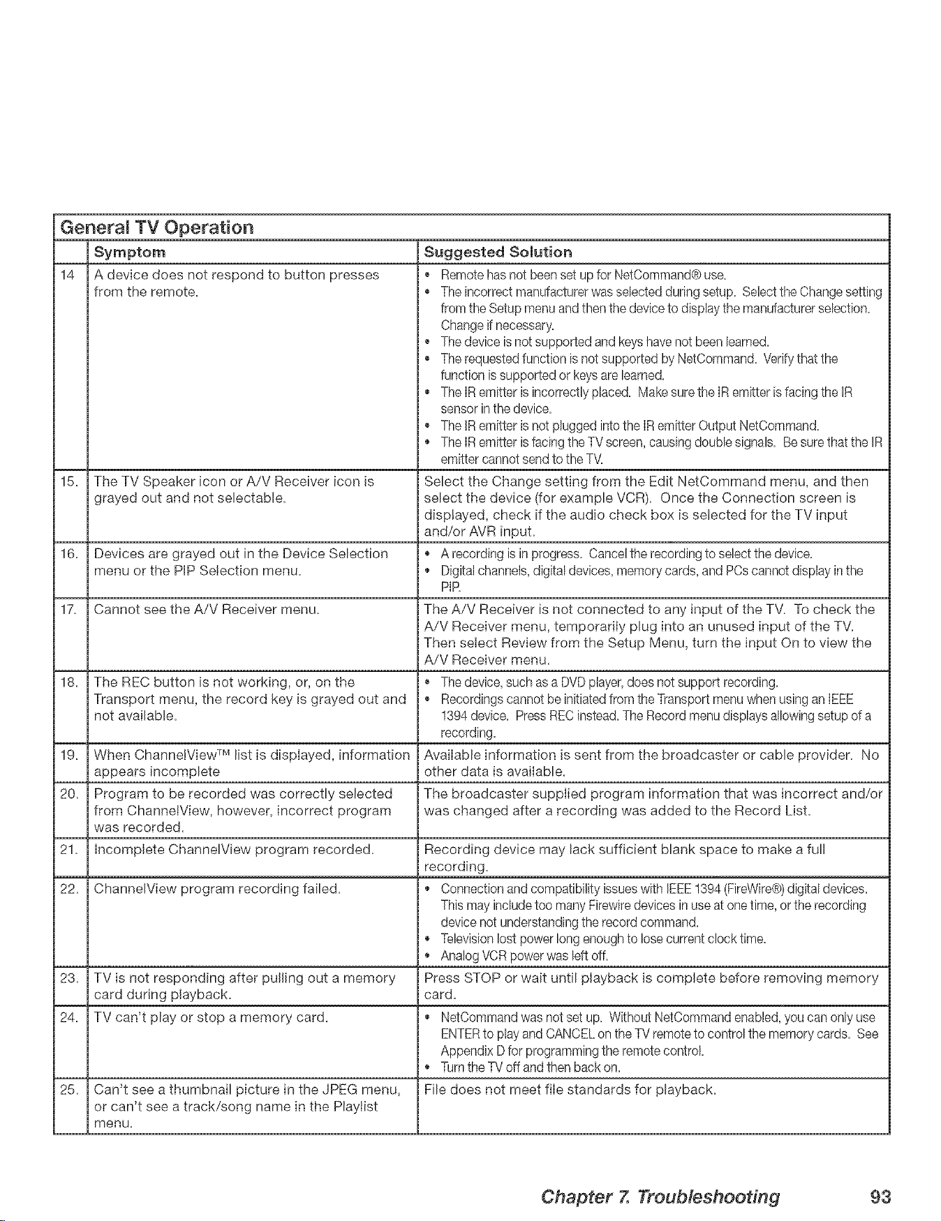
GeneraJ TV Operation
14
Suggested Somution
, • Remote hasnot been set up for NetCommand@use.
The incorrect manufacturer was selected during setup. Select the Change setting
from the Setup menu and then the device to display the manufacturerselection.
Change ifnecessary.
The device is not supported and keyshave not been learned.
, • The requested function is not supported by NetCommand. Verifythat the
function is supported or keysare learned.
The IR emitter is incorrectly placed. Make sure the IR emitter is facing the IR
sensor inthe device.
, • The JRemitter is not plugged into the IR emitter Output NetCommand.
The IR emitter is facing the TVscreen, causing double signals. Be sure that the IR
emitter cannot send to the T\L
15. The TV Speaker icon or A/V Receiver icon ls Select the Change setting from the Edit NetCommand menu, and then
grayed out and not sebctabb, select the device (for example VCR). Once the Connection screen is
displayed, check if the audio check box is selected for the TV input
and/or AVR input.
16. Devices are grayed out in the Device Selection * A recording is in progress. Cancel the recording to select the device.
menu or the PiP Selection menu. , * Digital channels,digital devices, memory cards, and PCscannot display in the
PiR
17. Cannot see the A/V Receiver menu. The A/V Receiver is not connected to any input of the TV. To check the
A/V Receiver menu, temporarJIy plug into an unused input of the TV.
Then select Review from the Setup Menu, turn the input On to view the
A/V Receiver menu.
18. The REC button is not working, or, on the , • The device, such as a DVDplayer, does not support recording.
Transport menu, the record key ls grayed out and • Recordings cannot be initiatedfrom the Transport menu when using an IEEE
not available. 1394 device. Press REC instead. The Record menu displays allowing setup of a
recording.
19. When ChannetView TM list is dispIayed, information AvaiIabb information is sent from the broadcaster or cable provider. No
appears incomplete other data is available.
20. Program to be recorded was correctly selected The broadcaster supplied program information that was incorrect and/or
from ChannetView, however, incorrect program was changed after a recording was added to the Record List.
was recorded.
21. incomplete ChanneWiew program recorded. Recording device may lack sufficient blank space to make a full
recording.
22. ChannelView program recording failed. , * Connection and compatibility issueswith IEEE1394 (FireWire@)digital devices.
This may includetoo many Firewiredevices in use at one time, orthe recording
device not understanding the record command.
, * Televisionlost power long enough to lose current clock time.
Analog VCRpower was left off.
23. TV is not responding after pulJlng out a memory Press STOP or wait until playback ls complete before removing memory
card during playback, card.
24. TV can't play or stop a memory card. , • NetCommand was not set up. Without NetCommand enabled, you can only use
ENTERto play and CANCELon the TV remote to control the memory cards. See
Appendix D for programmingthe remote control.
, • Turnthe TV off and then back on.
25. Can't see a thumbnail picture in the JPEG menu, File does not meet file standards for playback.
or can't see a track/song name in the Playtist
menu.
A device does not respond to button presses
from the remote.
Chapter 7. Troubleshooting 93
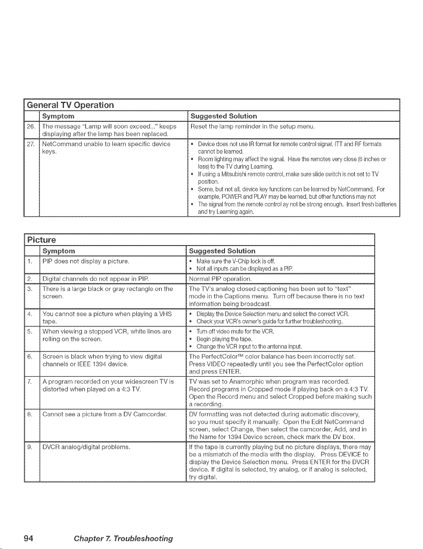
GeneramTV Operation
Suggested Solution
26. Reset the lamp reminder in the setup menu.
27.
i •
I ¢
o
The message "Lamp will soon exceed..." keeps
displaying after the lamp has been replaced.
NetCommand unable to learn specific device
keys.
Device does not use IR format for remote control signal. ITTand RFformats
cannot be learned.
Room lighting may affect the signal. Havethe remotes very close (6 inchesor
less)to the TV during Learning.
If using a Mitsubishi remote control, make sure slide switch is not set to TV
position.
Some, but not all, device keyfunctions can be learned by NetCommand. For
example, POWERand PLAYmay be learned,but other functions may not
The signal from the remote control ay not be strong enough. Insert fresh batteries
and try Learningagain.
Picture
1.
2.
3.
PiP does not display a picture.
Digital channels do not appear in PIR
There is a large black or gray rectangle on the
screen.
4. You cannot see a picture when playing a VHS
tape.
5. When viewing a stopped VCR, white lines are
rolling on the screen.
6. Screen is black when trying to view digita!
channels or IEEE 1394 device.
7. A program recorded on your widescreen TV is
distorted when played on a 4:3 TV.
8. Cannot see a picture from a DV Camcorden
9. DMCR analog/digital problems.
Suggested Solution
Make sure the V-Chip lock is off.
, * Not all inputs can be displayed as a PIR
Normal PiP operation.
The TV's analog closed captioning has been set to "text"
mode in the Captions menu. Turn off because there is no text
information being broadcast.
Displaythe DeviceSelection menuand select the correct VCR.
Check your VCR's owner's guide for further troubleshooting.
Turn off video mute for the VCR.
Begin playing the tape.
, • Change the VCRinput to the antenna input.
The PerfectCoIor TM color balance has been incorrectly set.
Press VIDEO repeatedly until you see the PerfectCoIor option
and press ENTER.
TV was set to Anamorphic when program was recorded.
Record programs in Cropped mode if playing back on a 4:3 TV.
Open the Record menu and select Cropped before making such
i a recording.
DV formatting was not detected during automatic discovery,
so you must specify it manually. Open the Edit NetCommand
i screen, select Change, then select the camcorder, Add, and in
the Name for 1394 Device screen, check mark the DV box.
if the tape is currently pIaying but no picture dispIays, there may
be a mismatch of the media with the display. Press DEVICE to
display the Device Selection menu. Press ENTER for the DVCR
device, if digital is selected, try analog, or if analog is selected,
try digital.
94 Chapter X Troubleshooting
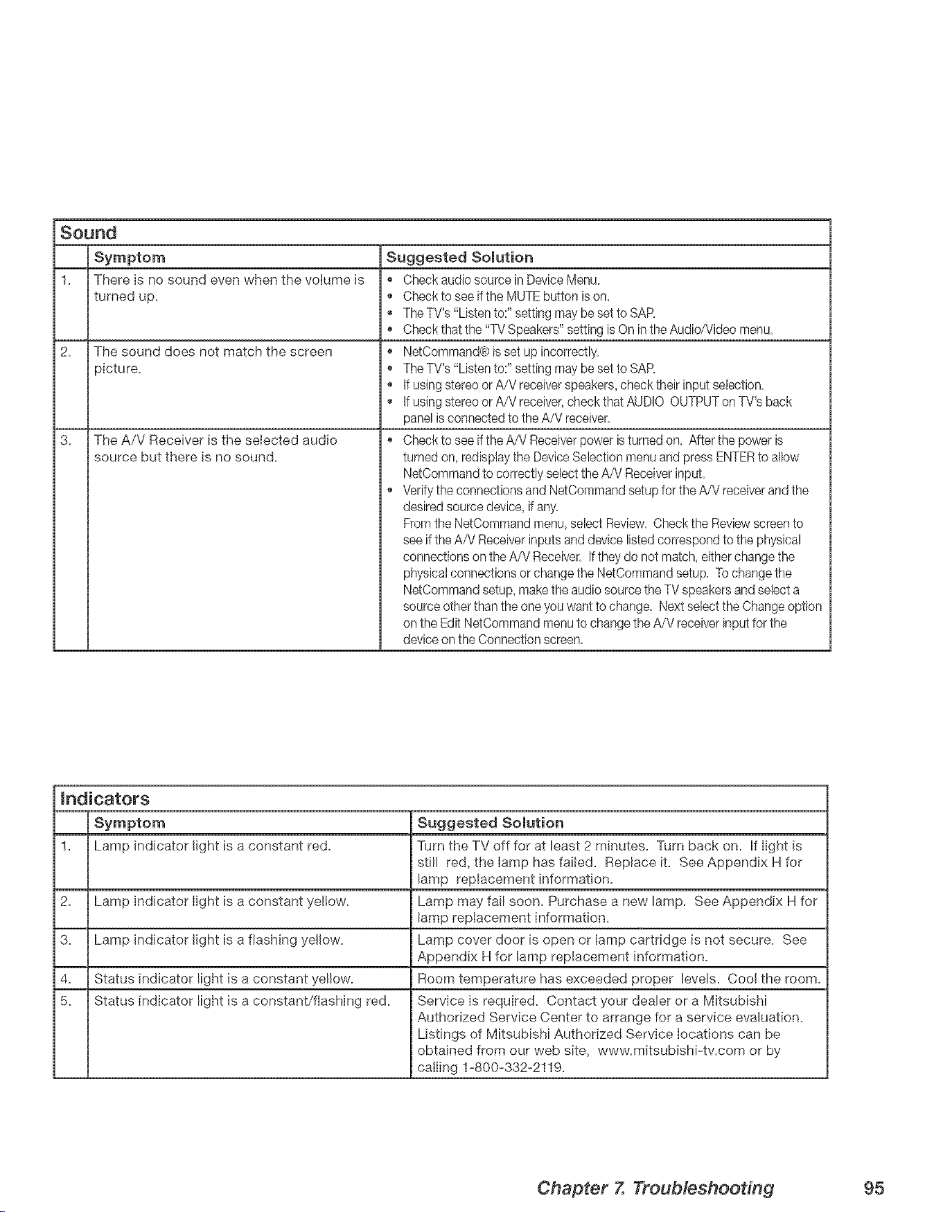
Sound
1. There is no sound even when the volume is
turned up.
2. The sound does not match the screen
picture.
3. The A/V Receiver is the selected audio
source but there is no sound.
Suggested Solution
Chock audio source in Device Menu.
Check to see ifthe MUTE button is on.
The TV's "Listen to:" setting may be set to SAR
Chock that the "TV Speakers" setting is On inthe Audio/Video menu.
NetCommand@is set up incorrectly.
The TV's "Listen to:" setting may be set to SAR
If using stereo or A/V receiver speakers, check their input selection.
If using stereo or A/V receiver,check that AUDIO OUTPUTonTV's back
panel is connected to the A/V receiver.
Check to see ifthe A/V Receiverpower is turned on. After the power is
turned on, redisplaythe Device Selection menu and press ENTERto allow
NetCommand to correctly select the A/V Receiverinput.
Verify the connections and NetCommand setup for the A/V receiver and the
desired source device, if any.
Fromthe NetCommand menu,select Review. Check the Review screento
see if the A/V Receiverinputs and device listed correspond to the physical
connections on theA/V Receiver. Iftheydo not match, either change the
physical connections or change the NetCommand setup. To change the
NetCommand setup, makethe audio source the TV speakers and select a
source otherthan the one you want to change. Next select the Changeoption
on the Edit NetCommand menu to change the A/V receiverinput for the
deviceon the Connection screen.
mndicators
Suggested Solution
1. Lamp indicator light is a constant red. Turn the TV off for at least 2 minutes. Turn back on. if light is
still red, the lamp has failed. Replace it. See Appendix H for
lamp replacement information.
2. Lamp indicator light is a constant yellow. Lamp may fail soon. Purchase a new lamp. See Appendix H for
lamp replacement information.
3. Lamp indicator light is a flashing yellow. Lamp cover door is open or lamp cartridge is not secure. See
Appendix H for lamp replacement information.
4. Status indicator light is a constant yellow. Room temperature has exceeded proper levels. Cool the room.
5. Status indicator light is a constant/flashing red. Service is required. Contact your dealer or a Mitsubishi
Authorized Service Center to arrange for a service evaluation.
Listings of Mitsubishi Authorized Service locations can be
obtained from our web site, www.mitsubishi-tv.com or by
calling 1-800-332-2119.
Chapter 7. Troubleshoodng 95
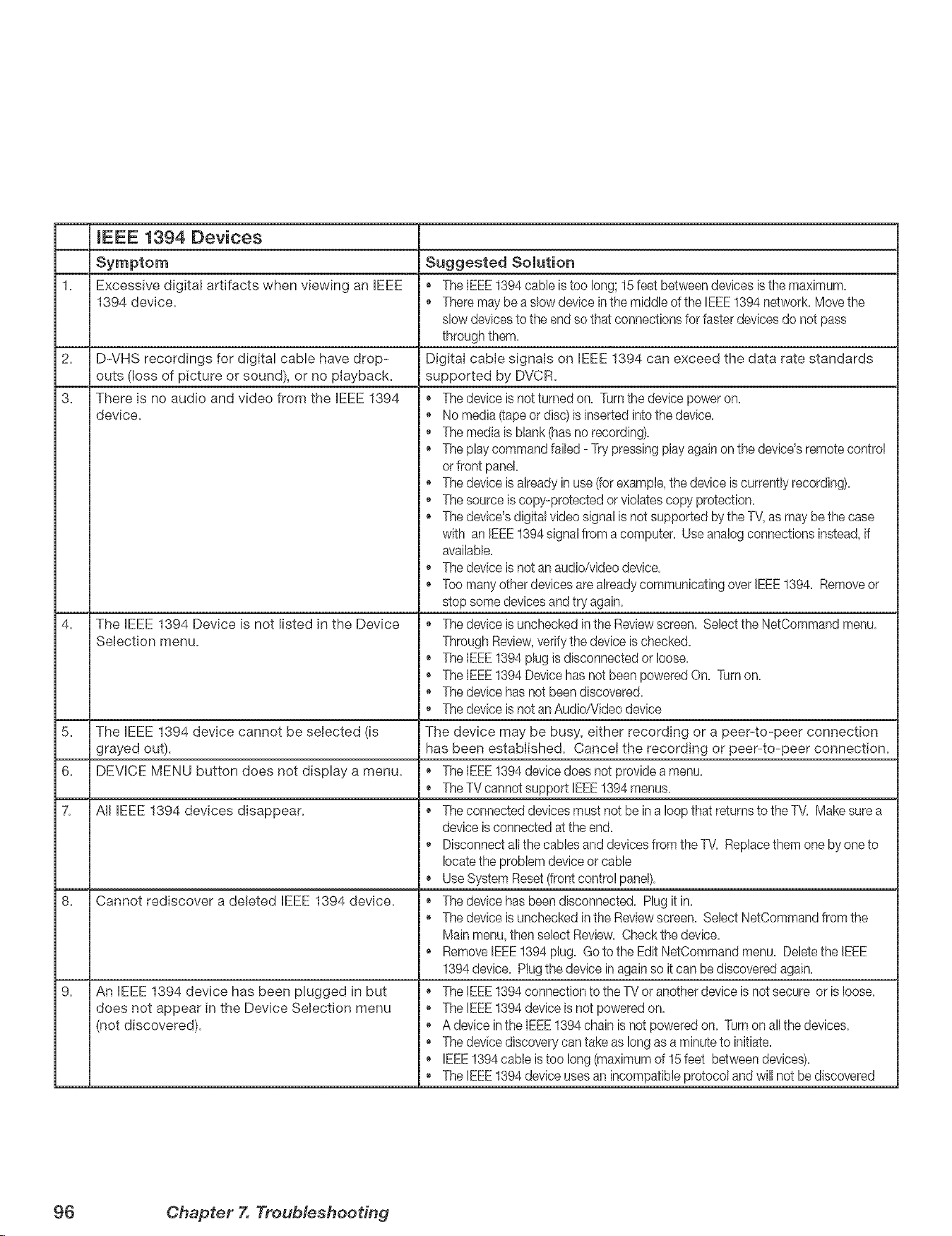
(EEE 1394 Devices
1= Excessive digital artifacts when viewing an IEEE
1394 device.
2.
3.
D-VHS recordings for digital cable have drop-
outs (loss of picture or sound), or no playback.
There is no audio and video from the IEEE 1394 +
device. +
The EEE 1394 Device is not listed in the Device
Selection menu.
5. The IEEE 1394 device cannot be selected (is
grayed out).
6. DEVICE MENU button does not display a menu.
7. All IEEE 1394 devices disappear.
8. Cannot rediscover a deleted IEEE 1394 device.
9. An EEE 1394 device has been plugged in but
does not appear in the Device Selection menu
(not discovered).
Suggested Solution
+ The IEEE1394 cable is too long; 15 feet between devices is the maximum.
+ There may bea slow device inthe middle of the IEEE!394 network. Move the
slow devicesto the end so that connections for faster devices do not pass
through them.
Digital cable signals on IEEE 1394 can exceed the data rate standards
supported by DVCR.
The device is not turned on. Turnthe device power on.
No media (-tapeor disc) is inserted into the device.
+ The media is blank (has no recording).
+ The play command failed - Try pressing play again on the device's remote control
orfront panel.
+ The device is already in use (-[orexample,the device is currently recording).
+ The source is copy-protected or violates copy protection.
, + The device's digital video signal is not supported by the TV,as maybe the case
with an IEEE1394 signal from a computer. Use analog connections instead, if
available.
, + The device is not an audio/video device.
, + Too many other devices are alreadycommunicating over IEEE1394. Remove or
stop some devices and try again.
+ The device is unchecked in the Reviewscreen. Select the NetCommand menu.
Through Review,verifythe device is checked.
+ The IEEE1394 plug is disconnected or loose.
+ The IEEE1394 Device has not been powered On. Turnon.
+ The device has not been discovered.
, + The device is not an Audio/Video device
The device may be busy, either recording or a peer-to-peer connection
has been established. Cancel the recording or peer-to-peer connection.
+ The IEEE1394 device does not provide a menu.
+ The TV cannotsupport IEEE1394 menus.
, + The connected devices must not be in a loop that returns to theTM Makesure a
device is connected at the end.
+ Disconnect allthe cables and devices from the TV. Replacethem one by one to
locatethe problem device or cable
+ Use System Reset (front control panel).
+ The device has been disconnected. Plug it in.
, + The device is unchecked in the Reviewscreen. Select NetCommand from the
Main menu,then select Review. Check the device.
+ Remove IEEE1394 plug. Go to the Edit NetCommand menu. Delete the IEEE
1394 device. Plugthe device in again so it can bediscovered again.
+ The IEEE1394 connection to the TV or anotherdevice is not secure or is loose.
+ The IEEE1394 device is not powered on.
, + A device inthe IEEE1394 chain is not powered on. Turn on allthe devices.
+ The device discovery can take as long as a minute to initiate.
+ IEEE1394 cable is too long (maximum of 15 feet between devices).
, + The IEEE1394 device uses an incompatible protocol and will not be discovered
96 Chapter 7. Troub/esheodng
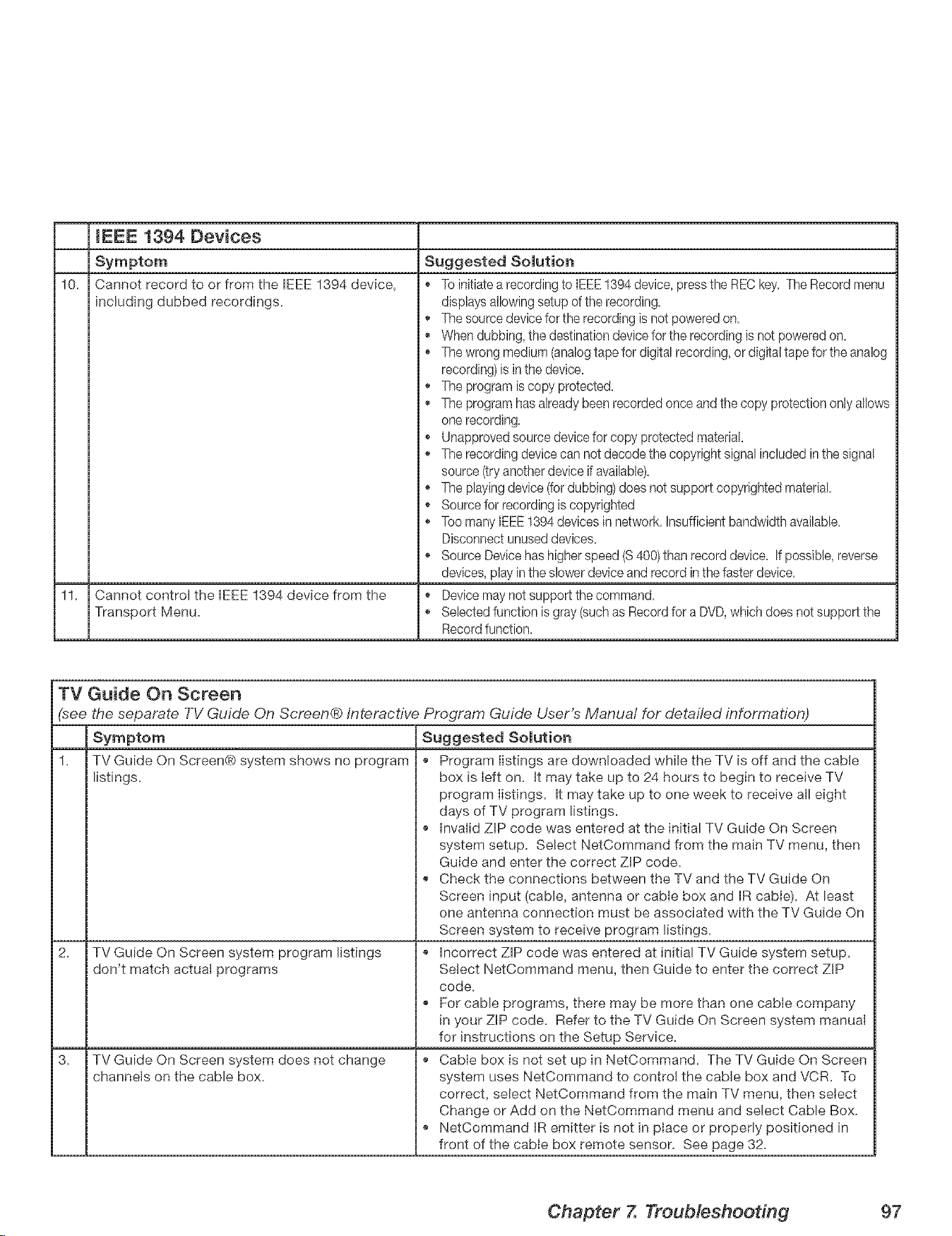
mEEE 1394 Devices
10+
Cannot record to or from the IEEE 1394 device,
including dubbed recordings.
11. Cannot control the IEEE 1394 device from the
Transport Menu.
TV Guide On Screen
(see the separate TV Guide On Screen® Interactive Program Guide User's Manuai for detailed information)
1.
Suggested Solution
+ To initiatea recording to IEEE1394 device, press the REC key. The Record menu
displays allowingsetup of the recording.
+ The source device for the recording is not powered on.
+ When dubbing, the destination device for the recording is not powered on.
+ The wrong medium (analogtape for digital recording, or digitattape for the analog
recording) is in the device.
+ The program is copy protected.
+ The program has already been recorded once and the copy protection only allows
one recording.
+ Unapproved source devicefor copy protected material
+ The recording device can not decode the copyright signal included inthe signal
source (try another device if available).
+ The playingdevice (fordubbing) does not support copyrighted material.
+ Source for recording is copyrighted
+ Too many IEEE1394 devices in network. Insufficient bandwidth available.
Disconnect unused devices.
+ Source Devicehas higherspeed (S 400)than record device. If possible, reverse
devices, play inthe slower device and record inthe faster device.
+ Device may not support the command,
+ Selected function is gray (such as Record for a DVD,which does not support the
Record function.
TV Guide On Screen® system shows no program
listings.
TV Guide On Screen system program listings
don't match actual programs
TV Guide On Screen system does not change
channels on the cable box.
Suggested Solution
+ Program listings are downloaded while the TV is off and the cable
box is Ieft on. It may take up to 24 hours to begin to receive TV
program listings. It may take up to one week to receive all eight
days of TV program listings.
+ Invalid ZIP code was entered at the initial TV Guide On Screen
system setup. Select NetCommand from the main TV menu, then
Guide and enter the correct ZIP code.
+ Check the connections between the TV and the TV Guide On
Screen input (cable, antenna or cable box and IR cable). At least
one antenna connection must be associated with the TV Guide On
Screen system to receive program listings.
+ Incorrect ZIP code was entered at initial TV Guide system setup.
Select NetCommand menu, then Guide to enter the correct ZIP
code.
+ For cable programs, there may be more than one cable company
in your ZIP code. Refer to the TV Guide On Screen system manual
for instructions on the Setup Service.
+ Cable box is not set up in NetCommand. The TV Guide On Screen
system uses NetCommand to control the cable box and VCR. To
correct, select NetCommand from the main TV menu, then select
Change or Add on the NetCommand menu and select Cable Box.
+ NetCommand IR emitter is not in place or properly positioned in
front of the cable box remote sensor. See page 32.
Chapter 7. Troubleshoodng 97

ices
Appendix A: Specifications ........................... 100
Appendix B: On-Screen information Displays .............. 102
Appendix C: Bypassing the V=Chip Lock .................. 103
Appendix D: Remote Control Programming Codes .......... 105
Appendix E: Device Control with NetCommand® ........... 108
Appendix F: NetCommand® Specialized Device Keys ........ 110
Appendix G: Cleaning and Service ...................... 111
Appendix H: Lamp Cartridge Replacement ................ 112
Appendix [: Recording and Viewing Combinations .......... 114
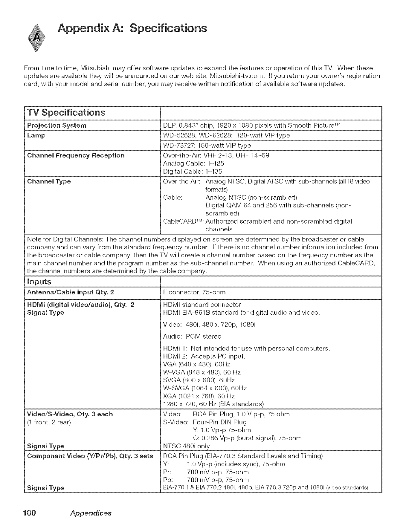
Appendix A: Specifications
From time to time, Mitsubishi may offer software updates to expand the features or operation of this TV. When these
updates are available they will be announced on our web site, Mitsubishi-tv.com. If you return your owner's registration
card, with your model and serial number, you may receive written notification of available software updates.
TV Specifications
DLP, 0.843" chip, 1920 x 1080 pixels with Smooth Picture TM
WD-52628, WD-62628: 120-watt VlP type
WD-73727: 150-watt VIP type
Over-the-Air: VHF 2-13, UHF 14-69
Analog Cable: 1-125
Digital Cable: 1-135
Over the Air: Analog NTSC, Digital ATSC with sub-channels (all18v_deo
formats)
Cable: Analog NTSC (non-scrambled)
Digital QAM 64 and 256 with sub-channels (non-
scrambled)
CableCARDTM:Authorized scrambled and non-scrambled digital
channels
Note for Digital Channels: The channel numbers displayed on screen are determined by the broadcaster or cable
company and can vary from the standard frequency number. If there is no channel number information included from
the broadcaster or cable company, then the TV will create a channel number based on the frequency number as the
main channel number and the program number as the sub-channel number. When using an authorized CableCARD,
the channel numbers are determined by the cable company.
F connector, 75-ohm
Inputs
Antenna/Cable input Qty. 2
HDIVII (digital video/audio), Qty. 2
Signal Type
Video/S-Video, Qty, 3 each
(1 front, 2 rear)
Signal Type
Component Video (Y/Pr/Pb}, Qty. 3 sets
Signal Type
HDMI standard connector
HDMI EIA-861B standard for digital audio and video.
Video: 480i, 480p, 720p, 1080i
Audio: PCM stereo
HDMI 1: Not intended for use with personal computers.
HDMI 2: Accepts PC input.
VGA (640 x 480), 60Hz
W-VGA (848 x 480), 60 Hz
SVGA (800 x 600), 60Hz
W-SVGA (1064 x 600), 60Hz
XGA (1024 x 768), 60 Hz
1280 x 720, 60 Hz (EIA standards)
Video: RCA Pin Hug, 1.0 V p-p, 75 ohm
S-Video: Four-Pin DIN Plug
Y: 1.0 Vp-p 75-ohm
C: 0.286 Vp-p (burst signal), 75-ohm
NTSC 480i only
RCA Pin Hug (EIA-770.3 Standard Levels and Timing)
Y: 1.0 Vp-p (includes sync), 75-ohm
Pr: 700 mV p-p, 75-ohm
Pb: 700 mV p-p, 75-ohm
EIA-770.1& EIA 770.2 480i, 480p, EIA 770.3 720p and 1080i (video standards)
100 Appendices
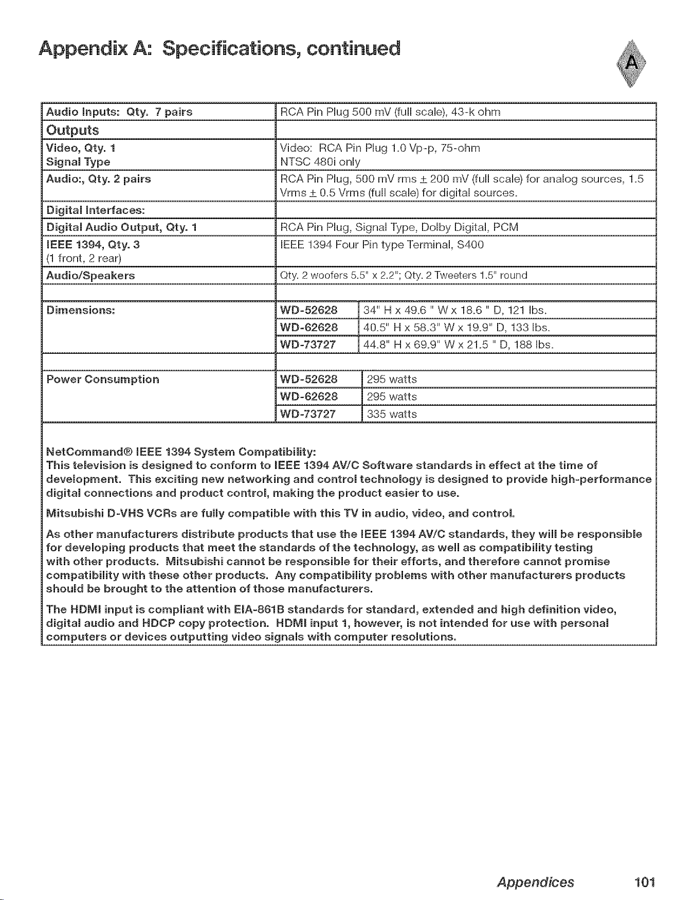
Appendix A: Specifications, continued
Audio Inputs: Qty. 7 pairs RCA Pin Hug 500 mV (full scaHe),43-k ohm
Outputs
Video, Qty. 1 Video: RCA Pin Hug 1.0 Vp-p, 75-ohm
Signal Type NTSC 480i only
Audio:, Qty. 2 pairs RCA Pin Hug, 500 mV rms ± 200 mV (full scale) for analog sources, 1.5
Vrms ± 0.5 Vrms (full scale) for digital sources.
Digital interfaces:
Digital Audio Output, Qty. 1 RCA Pin Hug, SignaHType, DoHby DigitaH, PCM
iEEE 1394, Qty. 3 IEEE 1394 Four Pin type TerminaH, $400
(1 front, 2 rear)
Audio/Speakers Qty=2 woofers 5=5"x 2=2";Qty=2 Tweeters 1=5"round
Dimensions:
Power Consumption
WD-52628
WD-62628
WD-73727
34" H x 49.6 " Wx 18.6 " D, 121 Hbs.
40.5" H x 58.3" W x 19.9" D, 133 Hbs.
44.8" H x 69.9" W x 21.5 " D, 188 Hbs.
WD-52628 295 watts
WD-62628 295 watts
WDW3727 335 watts
NetCommand® IEEE 1394 System Compatibility:
This television is designed to conform to mEEE1394 AV/C Software standards in effect at the time of
development. This exciting new networking and control technology is designed to provide high-performance
digital connections and product control, making the product easier to use.
Mitsubishi D-VHS VORs are fully compatible with this TV in audio, video, and control.
As other manufacturers distribute products that use the IEEE 1394 AV/C standards, they wimmbe responsibme
for devemoping products that meet the standards of the technomogy, as wemmas compatibimity testing
with other products, lViitsubishi cannot be responsibme for their efforts, and therefore cannot promise
compatibility with these other products. Any compatibility problems with other manufacturers products
should be brought to the attention of those manufacturers.
The HDIVil input is compmiant with EIA-861B standards for standard, extended and high definition video,
digital audio and HDCP copy protection. HDlVil input 1, however, is not intended for use with personal
computers or devices outputting video signals with computer resolutions.
Appendices 101
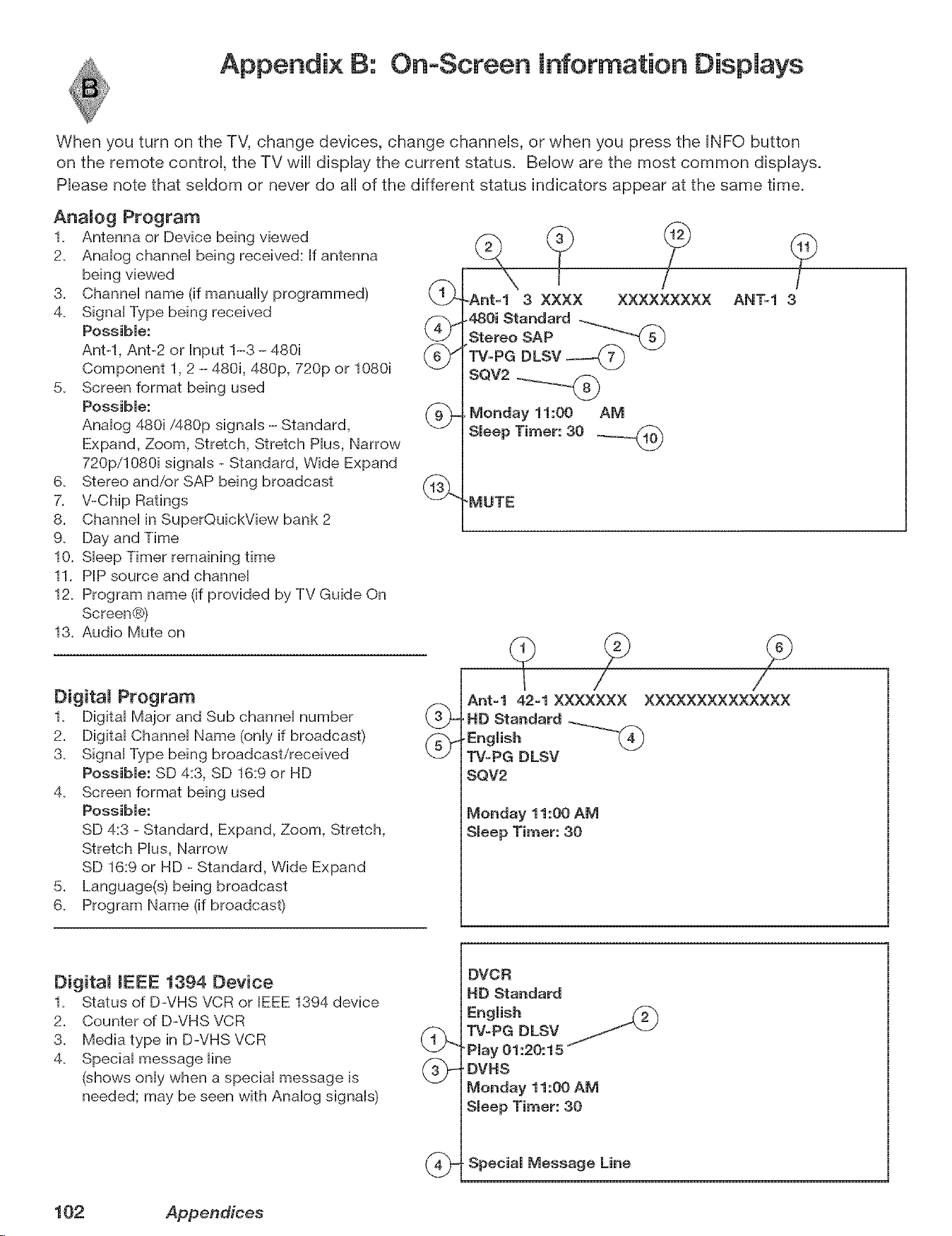
Appendix B: On+Screen Information Displays
When you turn on the TV, change devices, change channeUs, or when you press the INFO button
on the remote controU, the TV will dispUay the current status. BeUow are the most common dispUays.
PRease note that seMom or never do aH of the different status indicators appear at the same time.
Anamog Program
1+ Antenna or Device being viewed
2+ AnaHog channeH being received: If antenna
being viewed
3+ ChanneH name (if manually programmed) (1_
4+ SignaHType being received
Possible: _)
Ant-l, Ant-2 or Input 1-3 - 480i (_m¢'
Component 1, 2 - 480i, 480p, 720p or 1080i
\.._J
5. Screen format being used
Possible:
AnaHog 480i/480p signaHs - Standard, \-_J-
Expand, Zoom, Stretch, Stretch PHus,Narrow
720p/1080i signaHs - Standard, Wide Expand
Stereo and/or SAP being broadcast (13_
V-Chip Ratings
Channel in SuperQuickView bank 2
6+
7,
8,
9+
10. Sleep Timer remaining time
11+ PIP source and channel
12. Program name (if provided by TV Guide On
Screen®)
13. Audio Mute on
Digitam Program
1+ Digital Major and Sub channel number
2+ Digital Channel Name (only if broadcast)
3. Signal Type being broadcast/received
Possible: SD 4:3, SD 16:9 or HD
4. Screen format being used
Possible:
SD 4:3 - Standard, Expand, Zoom, Stretch,
Stretch Plus, Narrow
SD 16:9 or HD - Standard, Wide Expand
5+ Language(s) being broadcast
6. Program Name (if broadcast)
-Ant-1 3 XXXX XXXXXXXXX
480i Standard
StereoSAP
TV-PG DLSV
SQV2
Monday 11:00 AM
Smeep Timer: 30 _n_'_
?
AN%l 3
'MUTE
Ant-1 42-1 XXXXXXX XXXXXXXXXXXXXX
,HD Standard ..._.._._
TV-PG DLSV
SQV2
Monday 11:00 AM
Sleep Timer: 30
Digital IEEE 1394 Device
1+ Status of D-VHS VCR or IEEE 1394 device
2+ Counter of D-VHS VCR
3+ Media type in D-VHS VCR
4+ Special message line
(shows only when a special message is
needed; may be seen with Analog signals)
DVOR
HD Standard
English
TV-PG DLSV _ "+1
+Pmay01:20:15
' DVHS
Monday 11:00 AM
Sleep Timer: 30
. Special Message Line
102 Appendices
Appendix C:
the
!
VlChip Lock
p,P
0
0
® gg
:3
0 Cn
0
P_
lm
0
g_
mm
m
0
Bypassing the V-Chip Lock
After you set the Hock, you need your pass code to view
a V-Chip Hocked program, view the Hocked TV, canceH the
Hock,or enter the V-Chip Lock menus.
If you forget your pass code, you can view the Hocked
TV without entering your pass code. When you are
prompted for your pass code, press the number 9 and QV
buttons on the TV remote controH at the same time. This
process temporariHy unHocks the TV
When entering the V-Chip Lock menu, this process
deHetes your oHdpass code and prompts you to enter a
new pass code. Press HOME to exit the menu.
Deactivating the Front Button Lock
Press and hoHdthe MENU button on the TV front panel
for over eight seconds.
iliiiiii!,i_i'i'i_i'il_
iMPORTANT
When changing or deleting your pass
code, you must use the remote control
included with this TV. You cannot
use a Mitsubishi remote control from
another component or a "universal"
Appendices 103
m

This page intentionally bJank
104 Appendices
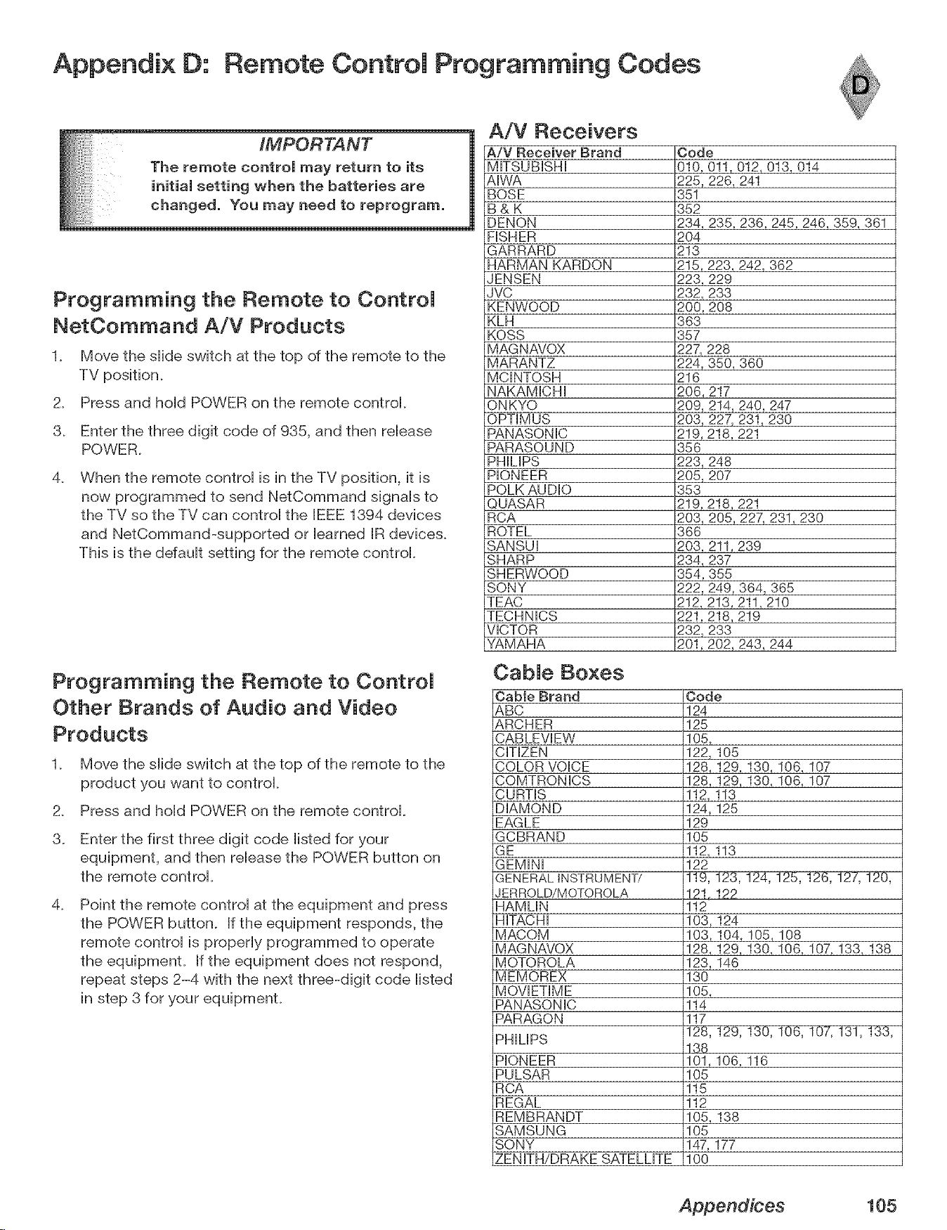
Appendix D: Remote Control Programming Codes
IMPORTANT
he remote controJ may return to its
nitiaJ setting when the batteries are
Programming the Remote to ControJ
NetCommand A/V Products
1. Move the slide switch at the top of the remote to the
TV position.
2. Press and hold POWER on the remote control.
3. Enter the three digit code of 935, and then release
POWER.
4_
When the remote control is in the TV position, it is
now programmed to send NetCommand signals to
the TV so the TV can control the BEEE1394 devices
and NetCommand-supported or barned JRdevices.
This is the ddault setting for the remote control.
Programming the Remote to ControJ
Other Brands of Audio and Video
Products
1_ Move the slide switch at the top of the remote to the
product you want to control
2_ Press and hold POWER on the remote control.
3_ Enter the first three digit code listed for your
equipment, and then release the POWER button on
the remote control.
4_
Point the remote control at the equipment and press
the POWER button. If the equipment responds, the
remote control is properly programmed to operate
the equipment. If the equipment does not respond,
repeat steps 2-4 with the next three-digit code listed
in step 3 for your equipmenL
A/V Receivers
A/V Receiver Brand
MITSUBISHI
AIWA
BOSE
B&K
DENON
FISHER
GARRARD
HARMAN KARDON
JENSEN
JVC
KENWOOD
KLH
KOSS
MAGNAVOX
MARANTZ
MCINTOSH
NAKAMICHI
ONKYO
OPTIMUS
PANASONIC
PARASOUND
PHIMPS
PIONEER
POLK AUDIO
QUASAR
RCA
ROTEL
SANSUI
SHARP
SHERWOOD
SONY
TEAC
TECHNICS
VICTOR
YAMAHA
Code
010, 0!1,012, 013, 014
225,226, 241
351
352
234, 235, 236, 245,246, 359, 361
2O4
213
215,223, 242, 362
223, 229
232, 233
200, 208
363
357
227, 228
224, 350, 360
216
206, 217
209, 214, 240, 247
203, 227, 231_ 230
219, 218, 221
356
223, 248
205, 207
353
219, 218, 221
203, 205, 227, 231,230
366
203, 211,239
234, 237
354,355
222, 249, 364, 365
212, 213, 211,210
221,218, 219
232_ 233
201,202, 243, 244
CabJe Boxes
OabJe Brand
&BC
&RCHER
CABLEVEW
CITIZEN
COLOR VOICE
COMTRONICS
CURTIS
DIAMOND
EAGLE
GCBRAND
GE
GEMiNi
GENERAL INSTRUMENT/
JERROLD/MOTOROLA
HAMLIN
HiTACHi
MACOM
M AG NAVOX
MOTOROLA
MEMOREX
MOVIETIME
PANASONIC
PARAGON
PHILIPS
PIONEER
PULSAR
RCA
REGAL
REMBRANDT
SAMSUNG
SONY
ZENITH/DRAKE SATELLITE
Code
124
125
105,
122,105
128,129,130,106,107
128,!29,130,106,107
112,113
124,125
129
105
112,113
122
121,122
112
103,124
103,104,105,108
128,129,130,106,107,133,138
123,146
130
105,
114
117
138
101,106,116
105
115
112
105,138
105
147,177
100
Appendices 105
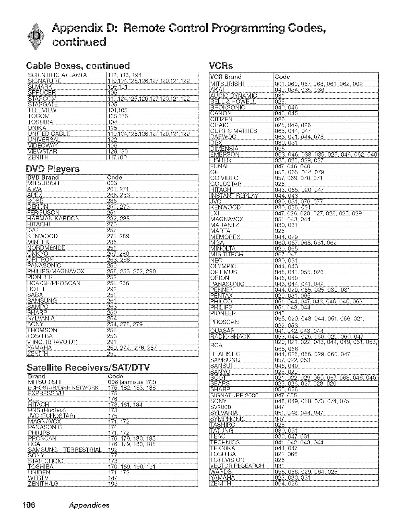
Appendix O: Remote Controm Programming Codes,
CabJe Boxes, continued
SCiENTiFiC ATLANTA
SIGNATURE
SLMARK
SPRUCER
STARCOM
STARGATE
TELEVIEW
TOCOM
TOSHIBA
UNIKA
UNITED CABLE
UNIVERSAL
VIDEQWAY
VIEWSTAR
ZENITH
112, 113, 194
119,124,125,126,127,120,121,122
105,101
105
119,124,125,126,127,120,121,122
105
101,105
135,136
104
125
119,124,125,126,127,120,121,122
122
106
129,130
117,100
DVD PJayers
DVD Brand
MITSUBISHI
AIWA
APEX
BOSE
DENON
FERGUSON
HARMAN KARDON
HiTACHi
JVC
KENWOOD
MINTEK
NORDMENDE
ONKYO
ORITRON
PANASONIC
PHILIPS/MAGNAVOX
PIONEER
RCA/G E/PROSCAN
ROTEL
SABA
SAMSUNG
SAMPO
SHARP
SYLVANIA
SONY
THOMSON
TOSHIBA
V INC+ (BRAVO D1)
YAMAHA
ZENITH
Code
003
261,274
266, 283
286
250 2_73
251
282, 288
27O
257
271,289
285
251
267, 280
263. 268
250
258 253 272, 290
252
25!, 256
292
251
261
263
260
264
254, 278, 279
251
253
291
250, 272, 276, 287
259
Satellite Receivers/SAT/[:)TV
Brand
MITSUBISHI
ECHOSTAR/DISH NETWORK
EXPRESS VU
G.E.
HiTACHi
_qhes)
JVC (ECHOSTAR)
MAG N AVOX
PANASONIC
PHILIPS
PROSCAN
RCA
SAMSUNG - TERRESTRIAL
SONY
STAR CHOICE
TOSHIBA
UNIDEN
WEBTV
ZENITH/LG
Code
006 _ame as 173)
175,182,183,188
175
176
173,181,184
173
175
171,172
174
171,172
176,179,180,185
176,179,180+185
192
177
173
170,189,190,191
171,172
187
193
VORs
VCR Brand
MITSUBISHI
AKAI
AUDIO DYNAMIC
BELL & HOWELL
BROKSONIC
CANON
CiTiZEN
Code
001,060,
049, 034,
031
025,
040, 046
043, 045
026
CRAIG 025, 049,
CURTIS MATHES 065, 044,
DAEWOO 063, 021,
DBX
DIMENSIA
EMERSON
FISHER
EUNAI
GE
GO VIDEO
GOLDSTAR
030, 031
065
063, 046,
025,
047,
053,
057,
026
HiTACHi 043,
iNSTANT REPLAY 044,
JVC 030,
KENWOOD 030,
LXI 047,
MAGNAVOX
MARANTZ
MARTA
MEMOREX
MGA
MINOLTA
MULTITECH
NEC
OLYMPIC
OPTIMUS
ORION
PANASONIC
PENNEY
PENTAX
PHILCO
PHILIPS
PIONEER
PROSCAN
QUASAR
RADIO SHACK
RCA
REALiSTiC
SAMSUNG
SANSUI
SANYO
051,
030,
026
044,
060, 067,
020, 065
067, 047
030, 031
044, 043
048,
046,
043,
044,
020,
051,
051,
043
065,
022,
041,
053,
020,
065,
044,
057,
046,
025+
SCOTT 021+
SEARS 025,
SHARP 055,
SIGNATURE 2000 047,
SONY 048,
SV2000
SYLVANIA
SYMPHONIC
TASHIRO
TATUNG
TEAC
TECHNICS
TEKNIKA
TOSHIBA
TQTEVISION
VECTOR RESEARCH
WARDS
YAMAHA
ZENITH
047
051,
047
026
030,
030,
041,
044,
021,
026
031
055,
025,
064,
067,068_061,062,002
035,036
026
047
044,078
038,039,023,045,062,040
028,029,027
046,040
065,044,079
069,070,071
065,020,047
O43
031,076,077
026,031
026,020,027,028,025,029
043,044
031
029
068,061,062
041,055,026
O4O
044,041,042
020,065,025,030,031
031,065
044,047,043,046,040,063
043,044
020,043,044,051,066,021,
O53
042,043,044
044,025,056,029,060,047
021,022,043,044,049,051,053,
066
025,056,029,060,047
022,053
O4O
029
022,029,060,067+068,046,040
026,027,028,020
O56
O55
049, 050, 073, 074, 075
043,044,047
031
047,031
042,043,044
O47
066
056,029,064,026
030,031
026
106 Appendices
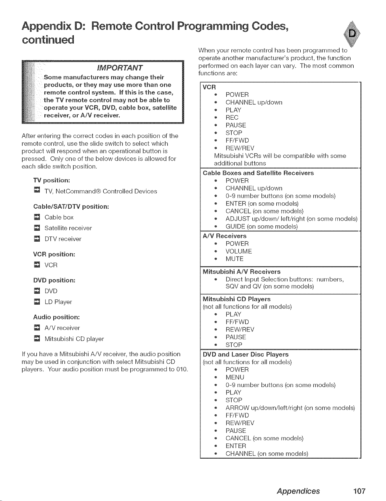
Appendix D: Remote Control Programming Codes,
IMPORTANT
Some manufacturers may change their
products, or they may use more than one
remote control system, If this i$ the case,
the TV remote control may not be able to
operate your VCR, DVD, cable box, satellite
receiver, or A/V receiver.
After entering the correct codes in each position of the
remote controk use the sHide switch to seHect which
product will respond when an operafionaH button is
pressed. OnHyone of the bellow devices is allowed for
each sHideswitch position.
TV position:
[] TV, NetCommand® Controlled Devices
Cable/SATIDTV position:
[] Cable box
[] Satellite receiver
[] DTV receiver
VCR position:
[] VCR
DVD position:
[] DVD
[] LD Player
Audio position:
[] AiV receiver
[] Mitsubishi CD player
If you have a Mitsubishi AiV receiver, the audio position
may be used in conjunction with select Mitsubishi CD
players. Your audio position must be programmed to 010.
When your remote control has been programmed to
operate another manufacturer's product, the function
performed on each layer can vary. The most common
functions are:
VCR
POWER
'_ PLAY
REC
PAUSE
STOP
FFiFWD
REWiREV
Mitsubishi VCRs will be compatible with some
additional buttons
Cable Boxes and Satellite Receivers
POWER
@
0-9 number buttons (on some models)
ENTER (on some models)
CANCEL (on some models)
ADJUST up/down/left/right (on some models)
GUIDE (on some models)
A/V Receivers
POWER
VOLUME
MUTE
Mitsubishi A/V Receivers
Direct Input Selection buttons: numbers,
SQV and QV (on some models)
Mitsubishi CD Players
(not all functions for all models)
'_ PLAY
FFiFWD
REWiREV
PAUSE
STOP
DVD and Laser Disc Players
(not all functions for all models)
POWER
MENU
0-9 number buttons (on some models)
'_ PLAY
STOP
ARROW up/down/left/right (on some models)
FF/FWD
REWiREV
PAUSE
CANCEL (on some models)
ENTER
CHANNEL (on some models)
Appendices 107
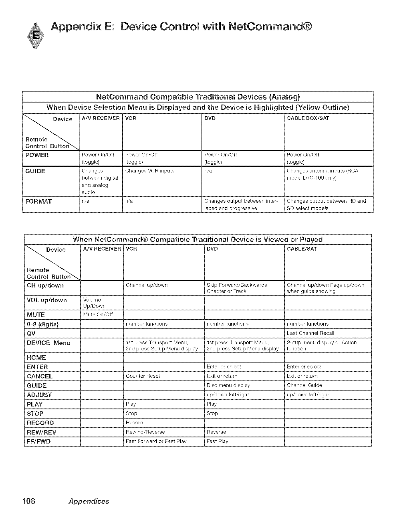
Appendix E: Device Controm with NetCommand®
NetCommand Compatibme Traditionam Devices (Anamog)
When Device Semection Menu is Dispmayed and the Device is Highmighted {Yellow Outmine}
e A/V RECEIVER VCR DVD CABLE BOX/SAT
POWER Power On/Off Power On/Off Power On/Off Power On/Off
(toggle) (toggle) (toggle) (toggle)
GUmDE Changes Changes VCR inputs n/a Changes antenna inputs (RCA
between digital model DTC-100 only)
and analog
audio
FORMAT n/a n/a Changes output between inter- Changes output between HD and
laced and progressive SD select models
When NetOommand® Compatibme Traditionam Device is Viewed or Pmayed
A/V RECEmVER VCR DVD CABLE/SAT
OH up/down Channel up/down Skip Forward/Backwards Channel up/down Page up/down
Chapter or Track when guide showing
VOL up/down Volume
Up/Down
MUTE Mute On/Off
0-9 {digits) number functions number functions number functions
QV Last Channel Recall
DEVICE Menu 1st press Transport Menu, 1st press Transport Menu, Setup menu display or Action
2nd press Setup Menu display 2rid press Setup Menu display function
HOME
ENTER Enter or select Enter or select
CANCEL Counter Reset Exit or return Exit or return
GUmDE Disc menu display Channel Guide
ADJUST up/down left/right up/down left/right
PLAY Play Play
STOP Stop Stop
RECORD Record
REW/REV Rewind/Reverse Reverse
FF/FWD Fast Forward or Fast Play Fast Play
108 Appendices
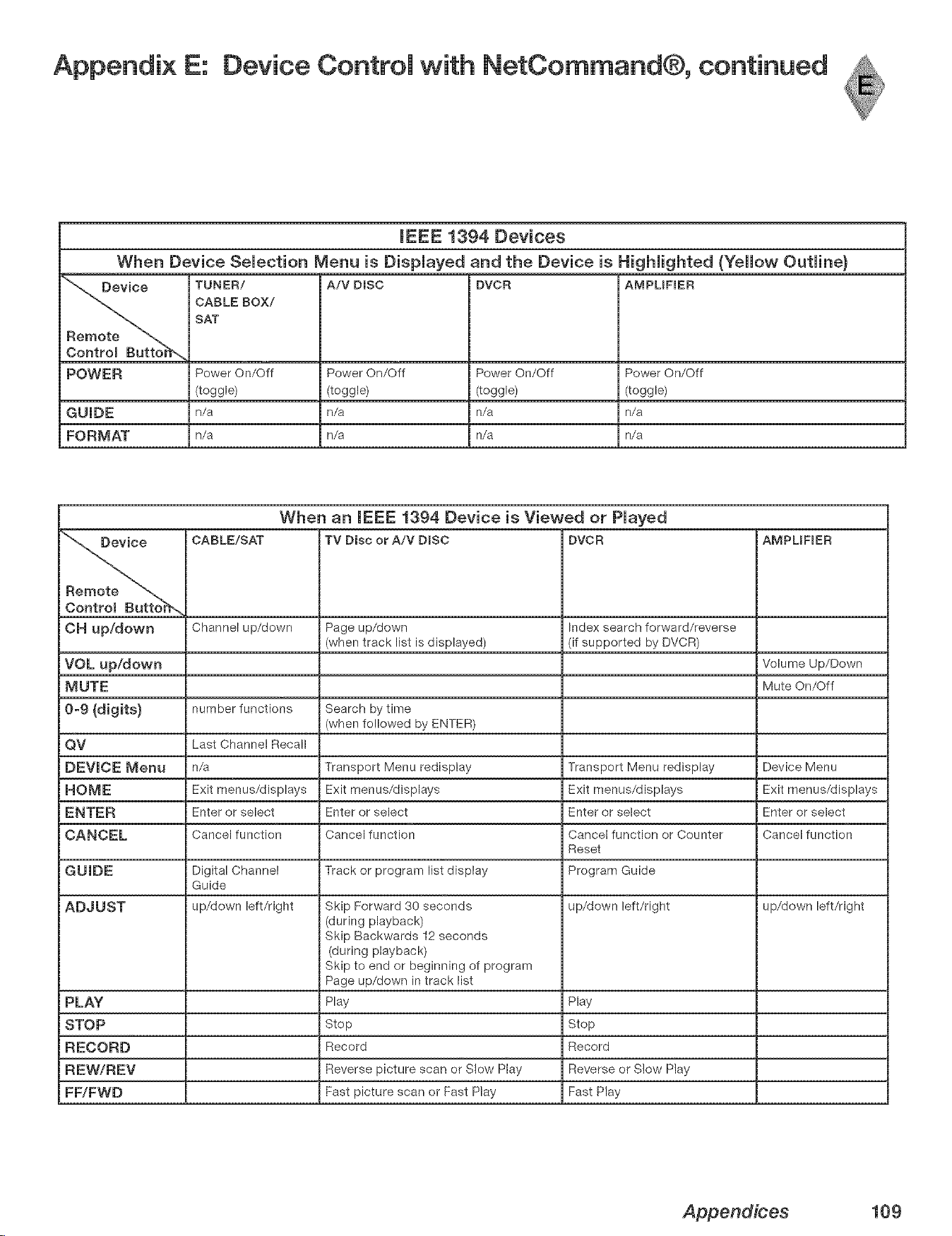
Appendix E: Device Control with NetCommand®, continued
mEEE 1394 Devices
When Device Selection Menu is Displayed and the Device is Highlighted (Yellow Outline)
'_ Device TUNER/ A/V DISC DVCR AMPUFIER
CABLE BOX/
SAT
Remote
Controm Butto_
POWER Power On/Off Power On/Off Power On/Off Power On/Off
(toggle) (toggle) (toggle) (toggle)
G U mD E n/a n/a n/a n/a
FORMAT n/a n/a n/a n/a
When an mEEE i394 Device is Viewed or Played
_ CABLE/SAT TV Disc or A/V DIRC DVCR AMPUFIER
OH Up/dOWn Channel up/down Page up/down Index search forward/reverse
(when track list is displayed) (if supported by DVCR)
VOL up/down Volume Up/Down
MUTE Mute On/Off
0-9 (digits) number functions Search by time
(when followed by ENTER)
QV Last Channel Recall
DEVICE Menu n/a Transport Menu redisplay Transport Menu redisplay Device Menu
HOME Exit menus/displays Exit menus/displays Exit menus/displays Exit menus/displays
ENTER Enter or select Enter or select Enter or select Enter or select
CANCEL Cancel function Cancel function Cancel function or Counter Cancel function
Reset
GUIDE Digital Channel Track or program list display Program Guide
Guide
ADJUST up/down left/right Skip Forward 30 seconds up/down left/right up/down left/right
(during playback)
Skip Backwards 12 seconds
(during playback)
Skip to end or beginning of program
Page up/down in track list
PLAY Play Play
STOP Stop Stop
RECORD Record Record
REW/REV Reverse picture scan or Slow Play Reverse or Slow Play
FF/FWD Fast picture scan or Fast Play Fast Play
Appendices 109
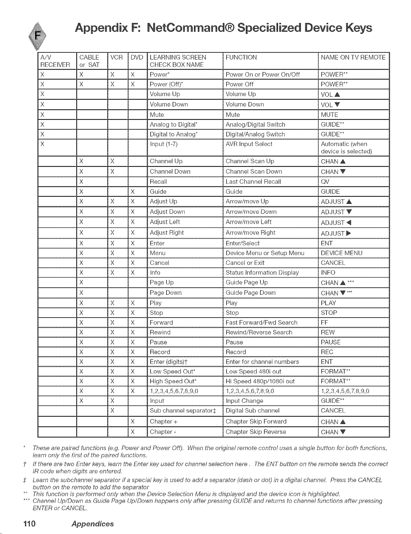
Appendix F: NetCommand® Specialized Device Keys
A/V
RECEIVER
X
X
X
X
X
X
X
X
CABLE VCR DVD
or SAT
X X X
X X X
LEARNING SCREEN
CHECK BOX NAME
Power*
Power (Off)*
Volume Up
Volume Down
Mute
Analog to Digital*
Digital to Analog*
Input (1-7)
X X Channel Up
X X Channel Down
X Recall
X X Guide
X X X Adjust Up
X X X Adjust Down
X X X Adjust Left
X X X Adjust Right
X X X Enter
X X X Menu
X X X Cancel
X X X Info
X Page Up
X Page Down
X X X Play
X X X Stop
X X X Forward
X X X Rewind
X X X Pause
X X X Record
X X X Enter (dlgits)t
X X X Low Speed Out*
X X X High Speed Out*
X X X 1,2,3,4,5,6,7,8,9,0
X X Input
X Sub channel separators
X Chapter +
X Chapter -
FUNCTION
Power On or Power On/Off
Power Off
Volume Up
Volume Down
Mute
Analog/Digital Switch
Digital/Analog Switch
AVR Input Select
Channel Scan Up
Channel Scan Down
Last Channel Recall
Guide
Arrow/move Up
Arrow/move Down
Arrow/move Left
Arrow/move Right
Enter/Select
Device Menu or Setup Menu
Cancel or Exit
Status Information Display
Guide Page Up
Guide Page Down
Play
Stop
Fast Eorward/Ewd Search
Rewind/Reverse Search
Pause
Record
Enter for channel numbers
Low Speed 480J out
Hi Speed 480p/10801 out
1,2,3,4,5,6,7,8,9,0
Input Change
Digital Sub channel
Chapter Skip Forward
Chapter Skip Reverse
NAME ON TV REMOTE
POWER**
POWER**
VOL A
VOL V
MUTE
GUIDE**
GUIDE**
Automatic (when
device is selected)
CHAN _k
CHAN V
QV
GUIDE
ADJUST A
ADJUST V
ADJUST 4
ADJUST
ENT
DEVICE MENU
CANCEL
INFO
CHAN ,A ***
CHAN Y **4
PLAY
STOP
EE
REW
PAUSE
REC
ENT
FORMAT**
FORMAT**
1,2,3,4,5,6,7,8,9,0
GUIDE**
CANCEL
CHAN A
CHAN Y
* These are paired functions (e.g. Power and Power Off). When the original remote control uses a single button for both functions,
learn only the first of the paired functions.
1- If there are two Enter keys, learn the Enter key used for channel selection here. The ENT button on the remote sends the correct
IR code when digits are entered.
7: Learn the subchannel separator if a special key is used to add a separator (dash or dot) in a digital channel Press the CANCEL
button on the remote to add the separator
** This function is performed only when the Device Selection Menu is displayed and the device icon is highlighted.
*** Channel Up/Down as Guide Page Up/Down happens only after pressing GUIDE and returns to channel functions after pressing
ENTER or CANCEL.
110 Appendices
Appendix G: Cmeaning and Service
Normally, light dusting with a dry, non-scratching duster wiii keep your TV clean. If cleaning beyond this is needed,
please use the following guidelines:
First, turn off the TV and unplug the power cord from the power outleL
Top and Sides of the TV:
Gently wipe down your TV with a soft, non-abrasive cloth such as cotton flannel or a clean cloth diaper, lightly
moistened with water. Dry with a second dry, soft, non-abrasive cloth.
For oily dirt, add a few drops of mild liquid detergent, such as dishwashing detergent, to the water used to moisten
the cloth. Rinse with a second cloth moistened only with water. Dry with a third dry, soft, non-abrasive cloth.
o Follow the instructions for the top and sides, however, wipe gently in an up and down motion, following the grooves
in the screen.
Clean the entire screen evenly, not just sections of the screen.
o Do not allow liquid to drip down the grooves of the screen, as some liquid may enter the TV between the screen
and the screen frame.
You may purchase Mitsubishi Screen Cleaner, part number CLEANERWSS, by calling (800) 553-727&
GeneraJ CJeaning Warnings:
DO NOT allow liquid to enter the TV through the ventilation slots or any crevice.
o DO NOT use any strong or abrasive cleaners as these can scratch the surfaces.
DO NOT use any cleaners with ammonia, bleach, alcohol, benzine, or thinners as these can dull the surfaces.
DO NOT spray liquids or cleaners directly on the TV's surfaces.
DO NOT scrub or rub the TV harshly. Wipe it gently.
Service
If you are unable to correct a problem with your TV, consult your Mitsubishi dealer or a Mitsubishi Authorized Warranty
Service Center.
DO NOT adjust any controls other than those described in this Owner's Guide.
DO NOT remove the protective back cover of your TV.
Menus not described and shown in this owner's guide are designed for factory use and for authorized service
personnel. Damage caused to the TV by non-authorized changes or changes to these menus made by non-authorized
persons are not covered under warranty.
Appendices 111
Appendix H: Lamp Cartridge Replacement
BURN DANGE!!
During norrnam operation, the surfaces inside
the TV near the lamp are e×trememy hot.
TOUCH THE LAMP CARTRIDGE BY THE HANDLE ONLY
Do not touch the glass parts of the lamp cartridge.
CAUTION: if the temevision is on, press POWER to turn it off, Ammowthe temevision to coom for
one hour before attempting to repmace the marnp cartridge.
LAMP UFE
The Hightsource for this tebvision is a iamp, which is part of a iamp cartridge assemMy. The actual life of the lamp
in this television can vary, based on the lamp itself, the air temperature around the TV while it is operating, and your
viewing patterns. Warmer air or poor ventilation shortens the lamp life, as does turning the television on and off
When the end of the lamp's life is approaching, the TV displays a warning message for one minute when you power on
the TV. The message will reappear the next five times you turn on the TV. After you change the lamp cartridge, you
must reset the lamp reminder through the TV Setup menu. Otherwise, the warning message will appear again before
necessary. Mitsubishi warrants the lamp for one (1) year from date of the original purchase at retail. It is likely, however,
that the lamp wiii last significantly longer than this.
TO ORDER A NEW LAMP:
Caii (800) 332-2119. Please have model number,
serial number, and TV purchase date available.
After Warranty
Call (800) 553-7278. Order a new lamp for your
TV model as shown below.
TV Model Number
WD-52628
WD-62628
WD-73727
Lamp Part Number
915P026010
915P027010
WARNmNG:
Do not remove the lamp cartridge immediately after turning off the television_ You may get burned because of the
lamp's high temperature. Allow the television to cool for one hour before attempting to replace the lamp cartridge.
Do not remove the lamp cartridge except when replacing it. Careless treatment can result in injury or fire.
Do not touch the lamp glass elemenL It may be very hot and break, causing injuries or burns.
Be sure not to insert any metal or flammable object into the lamp cartridge opening, as it may cause fire or electrical
shock. If any object is inserted into the opening, unplug the AC cord of the TV and contact your dealer for service.
Install the lamp cartridge securely. Failure to do so may cause a fire.
Do not touch the lamp glass elements. Oils from your fingers may cause premature lamp failure.
The lamp in this product contains mercury. Disposal of mercury may be regulated due to environmental considerations.
For disposal or recycling information, please contact your local authorities or the Electronic Industries Alliance at:
wwwoeiaeoorg_
Appendices
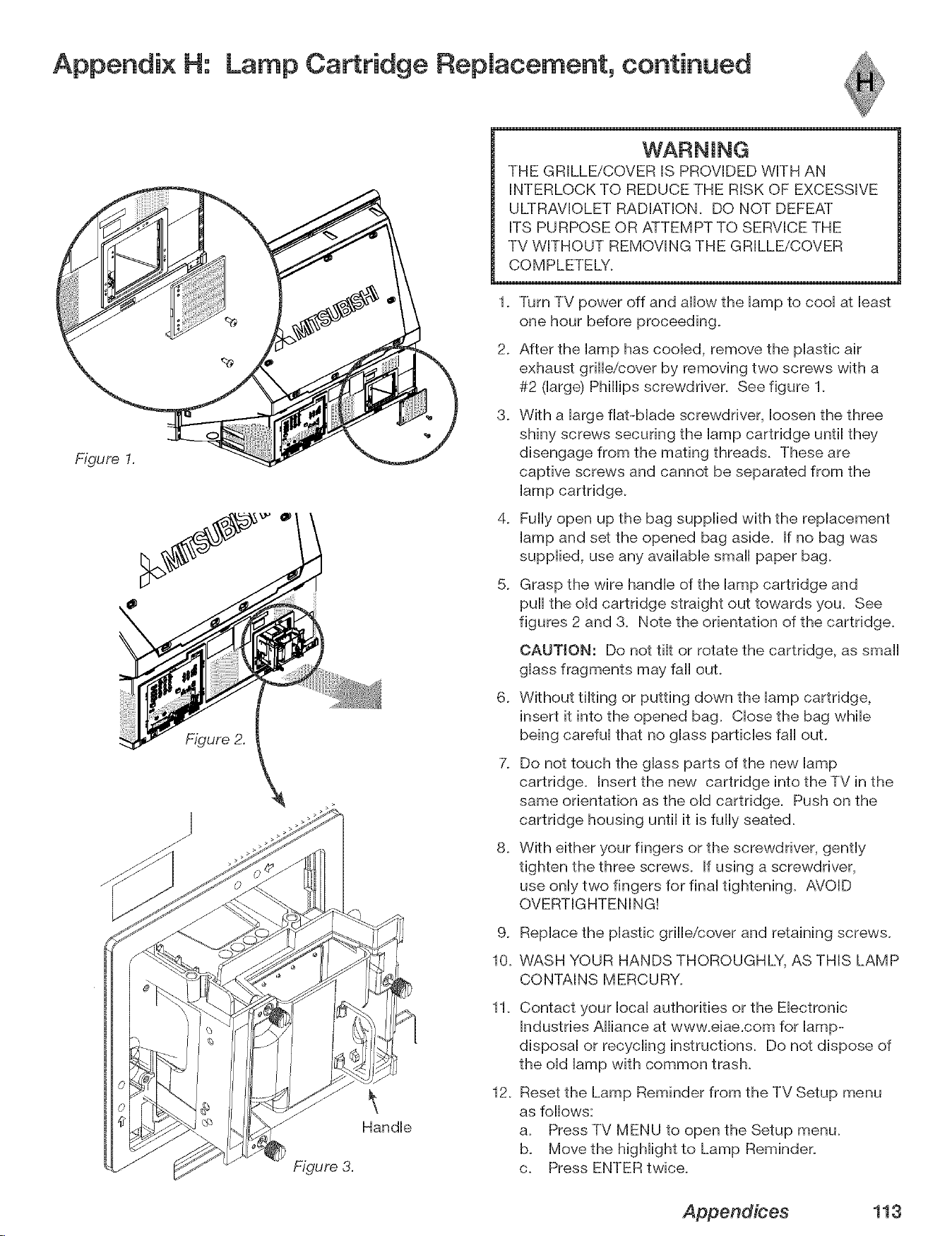
Appendix H: Lamp Cartridge Replacement, continued
Figure I.
Figure 2.
Figure 3.
Handle
THE GRILLE/COVER IS PROVIDED WITH AN
INTERLOCK TO REDUCE THE RISK OF EXCESSIVE
ULTRAVIOLET RADIATION. DO NOT DEFEAT
ITS PURPOSE OR ATTEMPT TO SERVICE THE
TV WITHOUT REMOVING THE GRILLE/COVER
COMPLETELY.
1. Turn TV power off and allow the lamp to cool at least
one hour before proceeding.
2. After the lamp has cooled, remove the plastic air
exhaust grille/cover by removing two screws with a
#2 0arge) Phillips screwdriver. See figure 1.
3. With a large flat-blade screwdriver, loosen the three
shiny screws securing the lamp cartridge until they
disengage from the mating threads. These are
captive screws and cannot be separated from the
lamp cartridge.
4. Fully open up the bag supplied with the replacement
lamp and set the opened bag aside. If no bag was
supplied, use any available small paper bag.
5. Grasp the wire handle of the lamp cartridge and
pull the old cartridge straight out towards you. See
figures 2 and 3. Note the orientation of the cartridge.
6_
CAUTION: Do not tilt or rotate the cartridge, as small
glass fragments may fall ouL
Without tilting or putting down the lamp cartridge,
insert it into the opened bag. Close the bag while
being careful that no glass particles fall ouL
7. Do not touch the glass parts of the new lamp
cartridge. Insert the new cartridge into the TV in the
same orientation as the old cartridge. Push on the
cartridge housing until it is fully seated.
8. With either your fingers or the screwdriver, gently
tighten the three screws. If using a screwdriver,
use only two fingers for final tightening. AVOID
OVERTIGHTENING!
9. Replace the plastic grille/cover and retaining screws.
10. WASH YOUR HANDS THOROUGHLY, AS THIS LAMP
CONTAINS MERCURY.
11.
Contact your local authorities or the Electronic
Industries Alliance at www.eiae.com for lamp-
disposal or recycling instructions. Do not dispose of
the old lamp with common trash.
12.
Reset the Lamp Reminder from the TV Setup menu
as follows:
a. Press TV MENU to open the Setup menu.
b. Move the highlight to Lamp Reminder.
c. Press ENTER twice.
Appendices 113
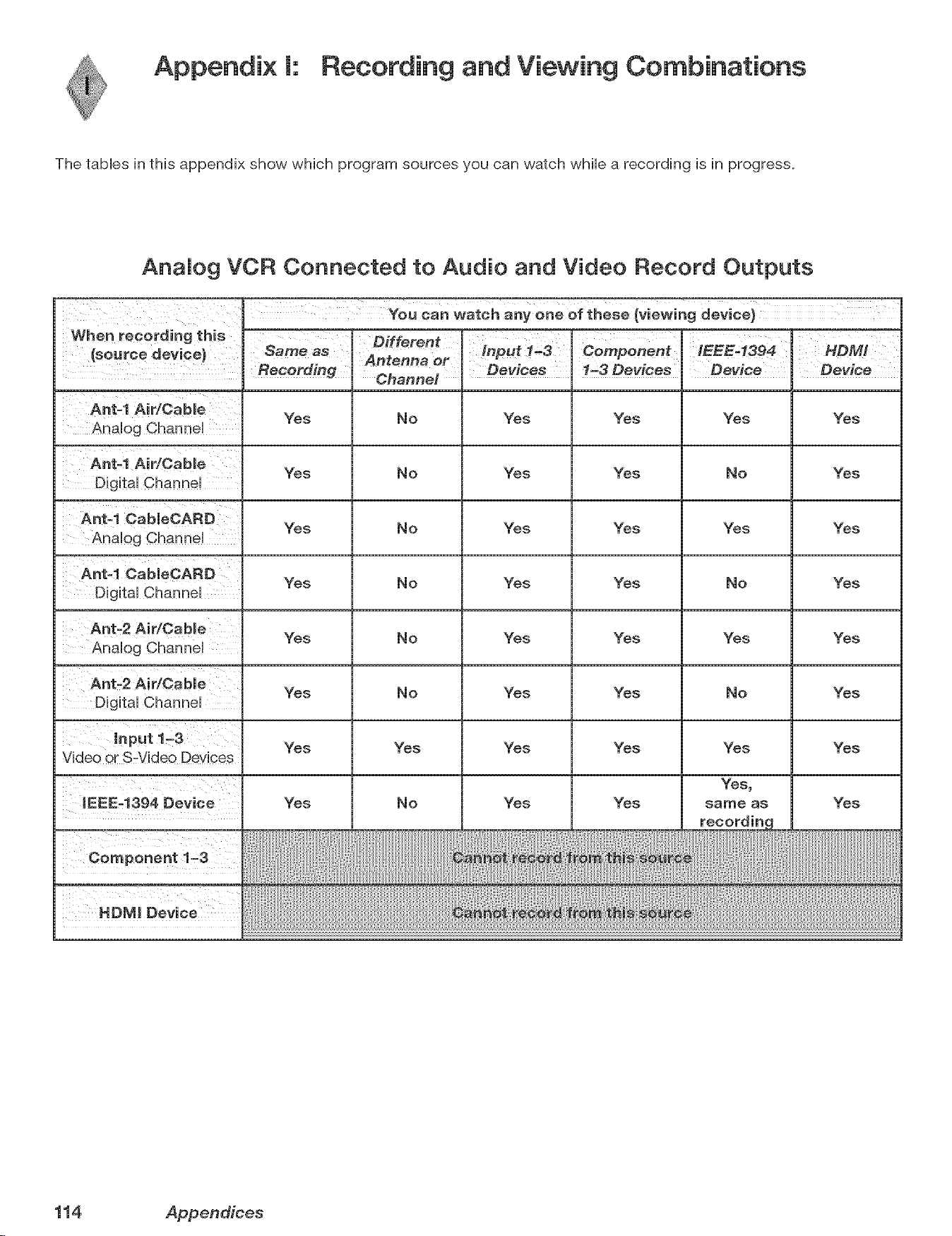
Appendix [: Recording and Viewing Combinations
The tables in this appendix show which program sources you can watch while a recording is in progress.
AnaMog VCR Connected to Audio and Video Record Outputs
Ant=l Air/Oabme Yes No Yes Yes Yes Yes
Ant=l Air/Oabme Yes No Yes Yes No Yes
Ant=l CabmeOARD Yes No Yes Yes Yes Yes
Ant=l Ca bleOARD Yes No Yes Yes No Yes
Yes No Yes Yes Yes Yes
Ant=2 Air/Cable Yes No Yes Yes No Yes
Yes Yes Yes Yes Yes Yes
Component 1_3
HOMI Device
Yes No Yes Yes
sa_e as
Yes
114 Appendices
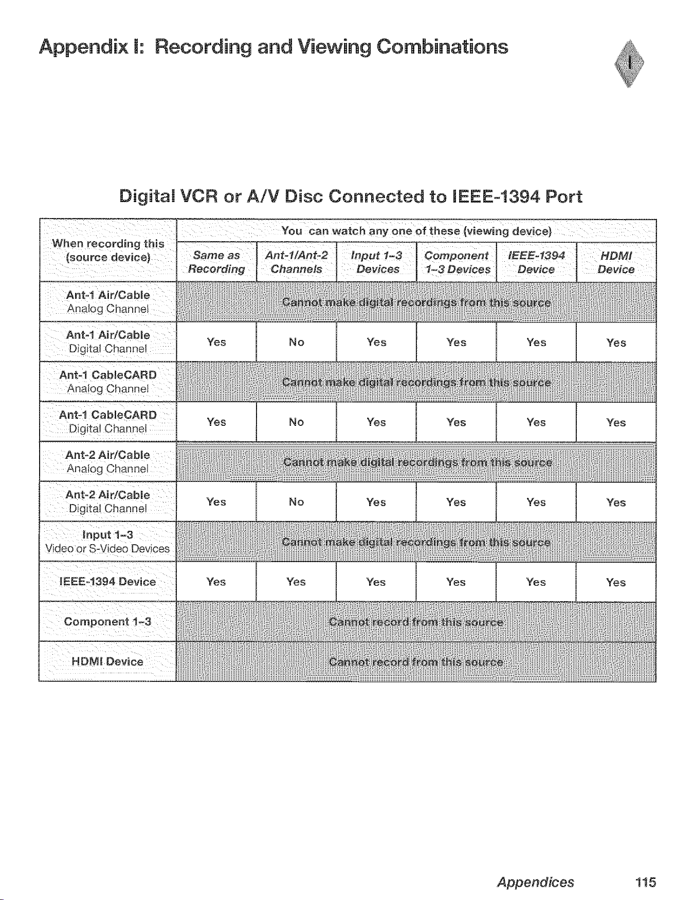
Appendix [: Recording and Viewing Combinations
Digital VCR or A/V Disc Connected to IEEE-1394 Port
When recording this
{source device)
Ant-I Air/Cable
Analog Channel
Ant-I Air/Cabme
Digital Channel
Ant-1 CabmeCARD
Analog Channel
Ant_l CableOARD
Digital Channel
Analog Cha
Same as
Recording
You can watch any one of these (viewing device)
Ant-l/Ant-2 Input 1-3 Component IEEE-1394 HDMI
Channels Devices 1-3 Devices Device
Yes No Yes Yes Yes Yes
Yes No Yes Yes Yes Yes
Yes No
Yes Yes
Yes
Yes
Yes Yes Yes
Yes Yes Yes
Appendices 115

Trademark and License Information
UCENSOR'S SUPPLIERS DO NOT MAKE OR PASS ON TO END USER OR ANY OTHER THIRD PARTY, ANY EXPRESS,
IMPMED OR STATUTORY WARRANTY OR REPRESENTATION ON BEHALF OF SUCH SUPPLIERS, INCLUDING, BUT
NOT MMITED TO THE IMPLIED WARRANTES OF NONqNFRINGEMENT, TITLE, MERCHANTABIUTY OR FITNESS
FOR A PARTICULAR PURPOSE
CableCARD TM is a trademark of Cable Television Laboratories, Inc.
CompactFlash@ and CF are trademarks of the CompactFlash Association.
DCRTM Certification Logo is a trademark of the Consumer Electronics Association.
Digital Light Processing TM and DLP TM are trademarks of Texas Instruments.
Manufactured under license from Dolby Laboratories. Dolby@ and the double-D symbol are registered trademarks of
Dolby Laboratories.
DTVUNK TM Certification Logo is a trademark of the Consumer Electronics Association.
Firewire@ is a trademark of Apple Computer, Inc. registered in the U.S. and other countries.
HDMr Mthe HDMI logo and High-Definition Multimedia Interface are trademarks or registered trademarks of HDMI
Licensing LLC.
Lifestyle@ 28 is a trademark of the Bose Corporation.
This product incorporates copyright protection technology that is protected by U.S. patents and other intellectual
property rights. Use of this copyright protection technology must be authorized by Macrovision, and is intended for
home and other limited pay-per-view uses only unless otherwise authorized by Macrovision. Reverse engineering or
_E_.0Y_-_,c.Memory Stick TM and Memory Stick PROTM are trademarks of Sony Corp.
Microdrive@ is a registered trademark of Hitachi Global Storage Technology, hc. in the United states and/or other
countries.
This product includes technology owned by Microsoft Corporation and cannot be used or distributed without a license
from Microsoft Licensing, Inc.
MultiMediaCard TM is trademark of Infineon Technologies and licensed to the MultiMediaCard Association.
The PanelLink Cinema Partners logo and the "PanelLink Cinema," "PLC" and "PLC Content Ready" word
mmm
P L C marks are trademarks of Silicon Image, hc. and are used under a license from Silicon Image, Inc or
PaneiLink Cinema, LLC.
Playstation@ 2 is a trademark of the Sony Corporation.
SD logo is a trademark.
SmartMedia TM is a trademark of Toshiba Corp.
In the United States, TV GUIDE and other related marks are registered marks of Gemstar-TV Guide International, Inc.
and/or one of its affiliates.
The TV Guide On Screen@ system is manufactured under license from Gemstar-TV Guide International, Inc. and/or one
of its affiliates.
The TV Guide On Screen@ system is protected by one or more of the following issued United States patents:
6,498,895; 6,418,556; 6,331,877; 6,239,794; 6,154,203; 5,940,073; 4,908,713; 4,751,578; 4,706,121.
XBox TM iS a trademark of the Microsoft Corporation.
MonitorLink TM, NetCommand@, ViewPoint@, QuickView TM, SuperQuickView TM, PerfectColor TM , MediaCommand TM,
ChanneIView TM are trademarks of Mitsubishi Digital Electronics America, Inc.
116 Trademark and Mcense Information
MITSUBISHI TV SOFTWARE
END-USER UCENSE AGREEMENT FOR EMBEDDED SOFTWARE
mMPORTANT = READ CAREFULLY: This License Agreement is a lega! agreement between you (either an individual or an entity)
and Mitsubishi Digital Electronics America, Inc. (MDEA) for all software pre installed and/or provided along with this television
("Software")= By utilizing this television and Software, you agree to be bound by the terms of this License Agreement=
The Software is protected by United States copyright laws and international treaty provisions, as well as other intellectual property
laws and treaties. The Software is licensed, not sold.
1. LICENSE GRANT. MDEA grants you a non-exclusive, non-transferable, limited right and license to use one copy of the
Software only with the Mitsubishi television model that included this owner's guide and owned by you.
2. RIGHTS AND LIMITATmONS.
Software Not for Resale. You may not resell or otherwise transfer for value the Software, except in conjunction with a sale of the TV
that Software has been pre installed.
Prohibition on Reverse Engineering, Decompilation and Disassembly. The Software contains trade secrets or other proprietary
material in its human perceivable form and to protect them, you may not reverse engineer, decompile, or disassemble, or otherwise
reduce the Software to any human perceivable form, except to the extent that the foregoing restriction is expressly prohibited by
applicable law.
Sejoaration of Components. The Software is licensed as a single product. Its component parts may not be separated for use on
more than one TM
No Rental You may not rent, lease, lend, or sublicense the Software.
Trademarks. This License Agreement does not grant you any rights to any trademarks of MDEA.
3. WOLATIONS. You understand that any use, copying or transfer of the Software, except as permitted pursuant to this License,
may subject you to serious criminal and civil penalties including damages and an award to MDEA of attorneys' fees in connection with
any violation of this License. You further understand that you may be held legally responsible for any copyright infringement or other
violation of inte!lectual property rights that is caused, encouraged, or induced by your failure to abide by the terms of the License.
This license is effective until terminated, and will terminate immediately without notice from MDEA or judicial resolution if you fail to
comply with any provision of this License.
4. COPYRIGHT, All title and intellectual property rights in and to the Software (including but not limited to any images,
photographs, animations, video, audio, music, text, and "applets" incorporated into the Software), and any accompanying printed
materials are owned by or licensed to MDEA. All title and intellectual property rights in and to the content which may be accessed
through use of the Software is the property of the respective content owner and may be protected by applicable copyright or other
intellectual property laws and treaties. This License Agreement grants you no rights to use such content, except that you own the
media on which the Software is recorded, but MDEA and its licensors retain ownership of the Software itself. All rights not expressly
granted are reserved by MDEA.
5. EXPORT RESTRICTIONS. MDEA is licensing the Software for use within the United States. You agree that you will not
export or re-export the Software. You specifically agree not to export or re-export the Software: (i) to any country to which the U.S.
has embargoed or restricted the export of goods or services, which currently include, but are not necessarily limited to Cuba, Iran,
Iraq, Libya, North Korea, Sudan, and Syria, or to any national of any such country, wherever located, who intends to transmit or
transport the Software back to such country; (ii) to any person or entity who you know or have reason to know will utilize the Software
in the design, development, or production of nuclear, chemical, or biological weapons; or (iii) to any person or entity who has been
prohibited from participating in U.S. export transactions by any federal agency of the U.S. government. You warrant and represent
that neither the BXA nor any other U.S. federal agency has suspended, revoked, or denied your export privileges.
6. DmSCLAmMER OF WARRANTY. EXCEPT AS OTHERWmSE PROVIDED _N THiS LICENSE OR iN THE LIMITED
WARRANTY APPUCABLE TO THE TV, MDEA MAKES NO OTHER WARRANTmES OF ANY KmND WHATSOEVER REGARDmNG
THE SOFTWARE AND HEREBY EXPRESSLY DISCLAIMS ALL WARRANTIES OF ANY KiND WHATSOEVER, EXPRESS OR
iMPLIED, WiTH RESPECT TO THE SOFTWARE. ALL iMPLiED WARRANTIES, iNCLUDiNG, WITHOUT LiMiTATiON, THE
mMPUED WARRANTIES OF MERCHANTABiLiTY AND FITNESS FOR A PARTICULAR PURPOSE ARE HEREBY EXPRESSLY
DISCLAIMED BY MDEA. iN NO EVENT SHALL MDEA BE LIABLE TO YOU OR ANY THIRD PARTIES, IN CONTRACT, iN TORT
OR OTHERWISE, FOR ANY DIRECT, INDRECT, SPECIAL, iNCiDENTAL OR CONSEQUENTIAL DAMAGES OF ANY KiND OR
NATURE. BECAUSE SOME JURISDICT_ONS DO NOT ALLOW THE EXCLUSION OR UMITATmON OF mMPUED WARRANTIES,
THE ABOVE LiMiTATiON MAY NOT APPLY TO YOU.
7= LIMITATION OF UABILITY. MDEA SHALL NOT, UNDER ANY C_RCUMSTANCES BE UABLE TO YOU OR ANY THIRD
PARTmES FOR ANY DAMAGES OF ANY NATURE, WHETHER mNDIRECT, SPECIAL, mNCIDENTAL, CONSEQUENTBAL
OF{ OTHERWISE, INCLUDING, BUT NOT LiMiTED TO, ANY CLAIMS FOR LOST PROFITS, LOSS OF GOOD WiLL OR
EXPENDmTURES MADE OR COMMITTED FOR mNRELIANCE ON THE CONTINUATmON OF THiS LICENSE. YOU AGREE
THAT NEmTHER MDEA'S BREACH OF THiS LICENSE NOR roTSFAILURE TO REPAIR A DEFECT, ERROR OF{ BUG SHALL
CONSTITUTE A FAILURE OF THE ESSENTIAL PURPOSE OF THIS UCENSE. BECAUSE SOME JURmSDmCTmONS DO NOT
ALLOW THE EXCLUSION OR LiMiTATiON OF LIABiLiTY FOB CONSEQUENTIAL OR iNCiDENTAL DAMAGES, THE ABOVE
LIMmTAT}ONS MAY NOT APPLY TO YOU. MDEA's liability to you for direct damages for any cause whatsoever and regardless
of the form of the action, will be Hmited to the money paid by you for the TV (based on fair market vamue of the TV) that
caused the damages.
8. GENERAL. This License Agreement will be governed by the laws of the State of California.
WARNING: This product contains chemicals known to the State of California to cause cancer and/or birth defects
or other reproductive harm.
Trademark and License information 117
Mitsubishi DLP TM Projection Television Limited Warranty
MITSUBISHI DIGITAL ELECTRONICS AMERICA, INC. ("MDEA') warrants as follows to the original purchaser of this
television from an authorized MITSUBISHI Audio/Video Dealer, should it prove defective by reason of against defects
arising from improper workmanship and/or material:
a. Parts. The lenticular (i.e. front picture) screen is warranted against defects in materials and workmanship for a
period of thirty (30) days from the date of the original purchase at retail. The lamp and all other parts (except any
software incorporated into this television) are warranted for a period of one (1) year from the date of the original
purchase at retail. We wiii repair or replace, at our option, any defective part without charge for the part. Parts used for
replacement may be replaced with those of like kind and quality and may be new or remanufactured. Parts used for
replacement are warranted for the remainder of the original warranty period.
b. Embedded Software. MDEA warrants that all software incorporated into this television set (the "Embedded
Software") wiii perform in accordance with the functional description of Embedded Software in aii material respects,
but MDEA does not warrant that the Embedded Software is error-free. MDEA also does not warrant that the Embedded
Software wiii be compatible under IEEE 1394 AWC and HAVi software standards with products produced by any other
manufacturer. The limited warranty contained in this section shall continue for a period of one (1) year from the date of
the original purchase at retail. If, after prompt notice within the warranty period, MDEA determines that the Embedded
Software has failed to perform in accordance with such functional description in all material respects and if such failure
is not due to accident, misuse, modification or misapplication of the Embedded Software, then MDEA shall modify or
replace the nonconforming Embedded Software at no charge to you, which at MDEA's sole discretion may be fulfilled
by means of modification or replacement software contained on a replacement memory card for Customer installation.
The foregoing shall be MDEA's sob obligation to you under this limited warranty. All rights under this limited warranty
on the Embedded Software also subject to your acceptance of and compliance with the terms of the Software License
Agreement applicable to this television, and this limited warranty on the Embedded Software shall be null and void if the
Embedded Software is modified or changed in any manner except as specifically authorized by MDEA.
c. Labor. For thirty (30) days after the original purchase at retail, we wiii repair or replace, at our option, the lenticular
screen if it proves defective. For certain items that are designed to be replaced by the consumer, including (but not
limited to) some Embedded Software, the consumer is solely responsible for any replacement labor. For all other parts,
we wiii provide the labor for a warranty repair by an authorized MITSUBISHI service center without charge for one (1)
year from the original date of purchase at retail.
d. Notice. To obtain warranty service, you must notify an authorized MITSUBISHI service center of any defect within
the applicable warranty time period.
e. This DLP Projection Television uses a single DLP chip to create the screen image. This technology creates the image
using small dots, or picture elements (pixeis). Your DLP Projection TV is manufactured to a high level of performance
and quality, in fact, 99.99% perfect in the number of properly functioning pixels. As in other display technology,
sometimes a pixei is continuously active, inactive or the incorrect color. Our standard is clear; MDEA warrants only that
the percentage of properly functioning pixeis wiii be not iess than 99.99% of aii pixeis.
BEFORE REQUESTING SERVICE, please review the instruction booklet to insure proper installation and correct
customer control adjustment, mfthe problem persists please arrange for warranty service.
1. TO OBTAIN WARRANTY SERVICE:
a. Contact your nearest authorized MITSUBISHI service center, whose name and address can be obtained from your
MITSUBISHI dealer, by writing at the address provided below, calling MDEA at the 800-332-2119, or by using the
support feature of our website at www.Mitsubishi-tv.com.
b. Warranty service wiii be provided in your home or, if required, at an authorized service shop, provided that your
television is located within the geographic territory customarily covered by an authorized MITSUBISHI service center. If
not, you must either deliver your television to an authorized service location at your own expense, or pay for any travel
and/or transportation costs the service center may charge to and from your home. Actual service labor will be provided
without charge.
c. Proof of purchase date from an authorized MITSUBISHI dealer is required when requesting warranty service. Present
your sales receipt or other document which establishes proof and date of purchase. THE RETURN OF THE OWNER
REGISTRATION CARD IS NOT A CONDITION QF COVERAGE UNDER THIS LIMITED WARRANTY. However, please
return the Owner Registration Card so that we can contact you should a question of safety arise which could affect you.
118

d. To obtain a replacement lamp during the warranty period, please contact the MDEA Consumer Relations Department
at (800) 332-2119. After the warranty period you may order the lamp directly from the MDEA Parts Department at (800)
553-7278.
2. THIS UMITED WARRANTY DOES NOT COVER:
a. Up to .01% pixel outages (small dot picture elements that are dark or incorrectly illuminated).
b. Damage to the lenticular screen or Fresnel lens, screen frame, cosmetic damage or to any other damage where
such damage is caused by unauthorized modification, alteration, repairs to or service of the product by anyone other
than an authorized MITSUBISHI service center; physical abuse to or misuse of the product (including any failure to
carry out any maintenance as described in the Owner's Guide including air filter cleaning or any product damaged by
excessive physical or electrical stress); any products that have had a serial number or any part thereof altered, defaced
or removed; product use in any manner contrary to the Owner's Guide; freight damage; or any damage caused by acts
of God or other factors beyond the reasonable control of MDEA, such as power surge damage caused by electrical
system or lightning. This limited warranty also excludes service calls where no defect in the product covered under
this warranty is found, service calls related to unsatisfactory audio or visual reception or signal unless caused by a
defect in the product that is covered under this limited warranty, all costs, expenses or any other damages arising from
product installation, or set-ups, any adjustments of user controls (including contrast, brightness, color, tint, fine tuning,
sharpness), other adjustment necessary to prepare the unit for display or use, connection with any external audio
receiver, antenna, cable or satellite systems, or service of products purchased or serviced outside the U.S.A. Please
consult the operating instructions contained in the Owner's Guide furnished with the product for information regarding
user controls.
3. ANY EXPRESS WARRANTY NOT PROVIDED HEREIN, AND ANY REMEDY WHICH, BUT FOR THIS PROVISION,
MIGHT ARISE BY IMPLICATION OR OPERATION OF LAW, IS HEREBY EXCLUDED AND DISCLAIMED. THE IMPLIED
WARRANTIES OF MERCHANTABILITY AND OF FITNESS FOR ANY PARTICULAR PURPOSE ARE EXPRESSLY
LIMITED TO A TERM OF ONE YEAR.
4. UNDER NO CIRCUMSTANCES SHALL MDEA BE LIABLE TO PURCHASER OR ANY OTHER PERSON FOR ANY
INCIDENTAL, SPECIAL OR CONSEQUENTIAL DAMAGES, WHETHER ARISING OUT OF BREACH OF WARRANTY,
BREACH OF CONTRACT, OR OTHERWISE.
5. Some states do not allow limitations on how long an implied warranty lasts, or the exclusion or limitation of incidental,
special, or consequential damages, so the above limitations or exclusions may not apply to you.
6. This limited warranty gives you specific legal rights, and you may also have other rights which vary from state to
state.
MITSUBISHI DIGITAL ELECTRONICS AMERICA, INC.
9351 Jeronimo Road
Irvine, CA 92618-1904
119
A
AiV Memory Reset. _%cReset
AiV Receiver
Adding 45
Connecting 28
Inputs 45
Input Learn Screen 46
Learn Screen 46
AiV Reset. 5'c__Reset
AiV Settings Descriptions
Audio 80
Video 81
Accessories, TV 10
Add Device..%c NetCommand
Advanced Learn Screen, [Device] 50
Antenna inputs (ANT-1 MAIN, ANT-2
AUX) 16
Antenna with Leads, Connecting 25
Audio/Video Menu 66, 79
Audio Inputs 16
B
Back Panel (illustrated 16
Batteries..1'a*e Remote Control
C
CabieCARD TM 11, 17, 23
CableCARD TM Menu 59
Cable Box 53, 108
Connecting 24, 27
Captions Menu 66, 74
Change Device Screen..1W NetCom-
mand
Channels 68, 72, 102. S_<*_/_.oSQV
and PIP viewing 86
Changing 72
Memorizing 67
Name 72
ChanneIView 60
Channel Menu 72
Cleaning and Service 111
Clock
Set Date, Time 67
Color Adjustments 81
Component Inputs (YPbPr) 16
Computer. 5'cc PC
Connecting: Helpful Hints 35
Connection for [Device] Screen 50
Connection Screen 55
Copy-Protected Material 62
D
Date..%e Clock
Daylight Savings Time 68
Demo Mode 20
Device Menu 59
Device Selection Menu 58
Digital Audio Output 17
Display Formats 87
DTV Link 17
DVD Hayer with Component Video,
Connecting 29
DVI Analog Audio 16
DVI Device 29
F
Film Mode 79
Format Definitions 87
Front Button Lock 77
Front Control Panel 12
G
GUIDE Key (button) 13, 14, 35, 60
H
HDMI Device 30
HDMI Input 17
HDTV Receiver with Component
Video, Connecting 30
m
Icon Order 69
IEEE 1394
Adding IEEE 1394 Devices Auto-
matically 54
and NetCommand 53
Compatible IEEE 1394 Devices
33
Connecting IEEE 1394 Devices
33
IEEE 1394 Device Type Screen
55
Inputs 17
Name for 1394 Device Screen
54
New 1394 Device Screen 54
Indicator Lights 95
Front Panel 12
Lamp Indicator 12
Power/Timer 13
Status 13
Inputs (Audio/Video) 16
IR (Infrared)
IR Code for [Device] Screen 51
IR Emitter NetCommand® 16,
32
J
JPEG Picture Thumbnails (Media
Dialog Box) 84
L
Lamp Cartridge Replacement 112
Lamp Indicator..fW Indicator Lights
Lamp Reminder 68
Language 67
"Learn" Feature
AiV Receiver 45, 46
Code Reference Chart 105
Description 22, 38, 39
Device 50
Device Key Reference Chart 110
GUIDE Key 35
IEEE 1394 Devices 55
Troubleshooting 93, 94
Learn Screen, [Device,] 49
Lock
Front Button Lock 77
Lock TV by Time 77
V-Chip Options 76
M
Memorize Channels. _%cChannels
Memory Cards 11
Media Setup Menu 85
Memory Card Reader 18, 19, 84
Playback 84
Mute
Audio 74, 102
MUTE key 14
Video Mute 79
N
Name Screen 47, 50
NetCommand
Add Device 48
Change Device 52
Connecting External Devices 22
Delete Device 52
Description 11
Device Control (reference chart)
108
Index
DeviceSetupScreen43
EditNetCommandScreen48
InitialSetup42
NetCommandMenu69
Pre-MemorizedDevices39
SpecializedDeviceKeys110
0
On-Screen Information 102
P
Pass Code
Resetting 103
Setting 76
PC 16, 17, 48, 54, 87
Connecting 31
Viewing 81, 89
Peer-to-Peer Connection 63
PerfectColor 81
PBP(Picture in Picture) 86
PBPDevice Selection Menu 58
Playlist Menu, MP3 or WMA7 85
Q
QV (QuickView TM) 14
R
Recording
Analog VCR and Viewing 114
Cancel Current Recordings 71
Default Digital (Record) Device
71
Digital VCR or AiV Disc and
Viewing 115
Record List Screen 61, 71
REC Button 14, 60, 61, 70, 93,
97
Setup 61, 70
Time-Delayed 61, 70
VCR Recording from an Antenna
or Cable Source 61
Remote Control
and NetCommand@ 39
Batteries 15
Functions 14
Programming 105
Programming Codes (reference
chart) 105
Transport Buttons 69
Reset
AiV (all settings) 13
AiV Memory (for individual de-
vices) 79
DVCR Counter 109
Lamp Reminder 68
Pass Code 103
PerfectColor 81
Remote Control 15
Reset Menu 20
System Reset Button 12, 20, 92
VCR Counter 108
Review Screen 44
RF Connection for Cable Screen 51
S
S-Video 28
Satellite Receiver 14, 22, 28, 30, 32,
39, 48, 53, 54, 60, 106, 107
Search AiV Disc. 5W AiV Discs
Setup Menu 66, 67
Signal Definitions 87
Speakers, TV 79
Specifications, TV 100
SQV (SuperQuickView TM) 73
Stand Requirements 2
Status indicator..1'_<* Indicator Lights
Stereo. 5'ceAiV Receiver
System Reset..%c Reset
T
Time..S'a*eClock
Timer 68
Time Zone 68
Track List Screen 64
Transport Menu 69
TV Guide On Screen 11, 14, 16, 24,
71, 72
Access Requirements 2
Setup 43
V
V-Chip 78
Bypassing the V-Chip Lock 103
Ratings 78
V-Chip Lock Menu 66, 76
V-Chip Menu 76
VCR 14, 16, 33, 54, 55, 58, 60, 94
and NetCommand Control 108,
109
Connecting 26, 27
NetCommand Default Input 22
NetCommand Pre-Memorized
Models 39
NetCommand Specialized De-
vice Keys 110
Programming Codes 106
Restrictions for Traditional VCRs
62
VCR for Recordings Screen 51
Video Inputs 16
Video Settings 81
W
Wall Outlet Cable 24
Index

_ JTSUgiSHI
ELECTRIC
DIGITAL T E L. EVISIQ NE_"
Website:
www, rnitsubishi-tv,com
To order repJacement or
additionaJ remote controJs, Jamp
cartridges, or Owner's Guides,
800_553W278
For questions, call Consumer
ReJations at
800-332t2119
© 2005 MitsubishiDJgitalEJectronics Amedca, hc. Written and Printedin U.S.A.
853B540B30