
Installation Guide
Microwave Built-In Trim Kit
1E
Minimum Cutout Opening Width 24-3/8" (619.13 mm)
Maximum Cutout Opening Width 24-11/16" (627.06 mm)
Minimum Cutout Opening Height 16
-
3/4" (425.5 mm)
Maximum Cutout Opening Height 17" (431.8 mm)
Maximum Height distance between holes 14-1/4" (361.825 mm)
Distance between centerline to holes
12-13/16" (324.65 mm)
Distance between holes A 25-9/16" (649.3 mm)
Distance between centerline to holes
14-5/16" (362.75 mm)
Distance between holes B 28-9/16" (725.5 mm)
15-13/32" (391.45 mm)
Center Line
BUILT-IN TRIM KIT TEMPLATE
FOR CUSTOM SERIES MICROWAVE OVEN
1. Align the mounting template center line with the center of the cutout
and the floor line with the floor of the cutout. Tape it into place.
2. For VMTK272, predrill 4 holes marked A with a 1/16" drill bit.
For VMTK302, predrill 4 holes marked B with a 1/16" drill bit.
3. Remove template from the cabinet.
TINSKB182MRR0
Floor Line of Cutout Opening
USE THIS SIDE OF TEMPLATE FOR MODELS
VMTK272 and VMTK302 ONLY.
1-5/32"
(29.6 mm)
IMPORTANT–Please Read and Follow!
• Before beginning, please read these instructions completely and carefully.
• Be sure to DISCONNECT THE PLUG of the microwave oven from the electrical outlet before installing the built-in trim kit.
Remove the turntable from the oven cavity.
• Because the kit includes metal parts, caution should be used in handling and installation to avoid the possibility of injury.
• Do not remove permanently afxed labels, warnings, or plates from the product. This may void the warranty.
• Please observe all local and national codes and ordinances.
• The installer should leave these instructions with the consumer who should retain for local inspector’s use and for
future reference.
• This built-in trim kit is designed for use ONLY WITH CONVECTION AND CONVENTIONAL MICROWAVE OVENS SPECIFYING
BUILT-IN TRIM KIT VMTK272, VMTK302, VMTK362, VMTK277, VMTK307 or VMTK367 on the rating label on the bottom
face plate of the oven cavity.
• YOUR OVEN CAN BE BUILT INTO A CABINET OR WALL BY ITSELF OR ABOVE ANY ELECTRIC WALL OVEN OR WARMING
DRAWER.
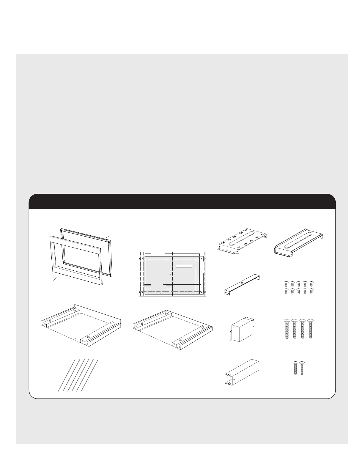
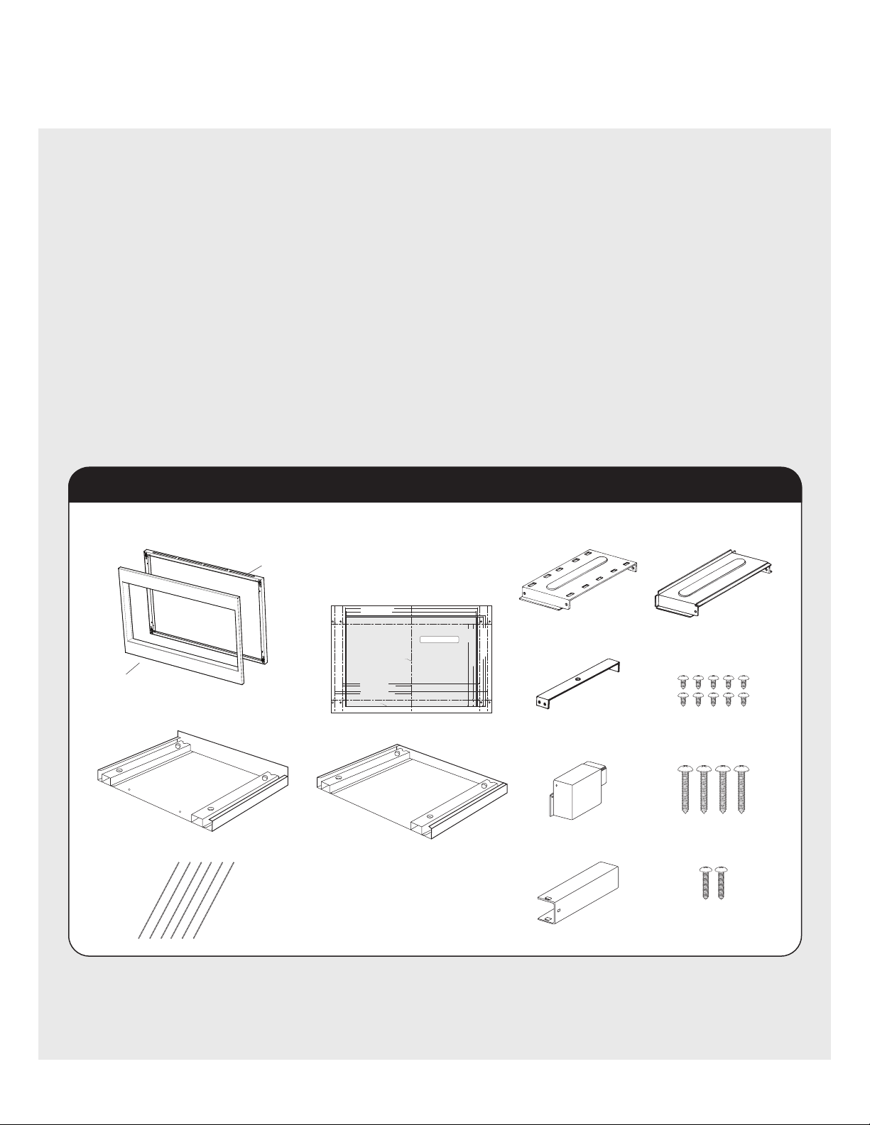
Parts Included in VMTK kits
Front Frame
QTY 1
Back Frame
QTY 1
Front Frame Assembly QTY 1
Bottom Duct Assembly QTY 1
Screw A (1/2" length)
QTY 10 *
Screw B (1-3/4" length)
QTY 4
27" & 30"Surface Mount
Template 2-sided
or 36"Surface Mount
Template single-sided
QTY 1
Cushion QTY 6 *
Duct (A)-1 QTY 1 * Duct (A)-3 QTY 1 *
Duct (B) QTY 1 *
*
Duct (C) QTY 1 *
Duct (A)-2 QTY 1 *
Screw C (3/4" length)
QTY 2
*VMTK277, VMTK307 and VMTK367 ONLY.
2 E
Basic Specifications
Microwave Oven Built-In Custom Trim Kits
Description CONVECTION VMOC206SS/VMOC506SS VMTK277 VMTK307
Overall Width 24-5/8" (62.5 cm) 26-1/2" (67.3 cm) 29-1/2" (74.9 cm)
Overall Height
from Bottom
14-7/8" (37.7 cm) 19-13/16" (50.1 cm) 19-1 3/ 1 6" (50.1 cm)
Overall Depth
from Rear
19" (48.3 cm) N/A
Oven Interior
Width
Height
Depth
Overall
16-1/8"
9-5/8"
16-1/8"
1.5 cu. ft.
(40.9 cm)
(24.4 cm)
(40.9 cm)
N/A
Cutout Width N/A
Min.
Max.
25"
25-3/8"
(63.5 cm)
(64.5 cm)
Cutout Height N/A 18-11/16" (46.9 cm)
Cutout Depth N/A
Min.
Max.
20-1/8"
N/A
(51.1 cm)
N/A
Electrical
Requirements
120VAC/60 Hz (UL)
117VAC/60 Hz (CSA)
N/A
Maximum Amp
Usage
1.55 KW
1.5 KW
13 amps (UL)
13 (CSA)
N/A
Approximate
Shipping Wt.
60 lbs. (27.2 kg) 19 lbs. (8.6 kg) 20 lbs. (9.1 kg)
Description CONVENTIONAL VMOS201SS/VMOS501SS VMTK272 VMTK302
Overall Width 24" (60.9 cm) 26-1/2" (67.3 cm) 29-1/2" (74.9 cm)
Overall Height
from Bottom
13-3/8" (33.9 cm) 18-1/4" (46.3 cm) 18-1/4" (46.3 cm)
Overall Depth
from Rear
19-1/4" (48.9 cm) N/A
Oven Interior
Width
Height
Depth
Overall
17-3/8"
10-1/2"
18-5/8"
2.0 cu. ft.
(44.1 cm)
(26.6 cm)
(47.3 cm)
N/A
Cutout Width N/A
Min.
Max.
24-3/8"
24-11/16"
(61.9 cm)
(62.7 cm)
Cutout Height N/A
Min.
Max.
16-3/4"
17"
(42.5 cm)
(43.2 cm)
Cutout Depth N/A
Min.
Max.
20"
N/A
(50.3 cm)
N/A
Electrical
Requirements
120VAC/60 Hz N/A
Maximum Amp
Usage
1.5 KW 13 amps N/A
Approximate
Shipping Wt.
46 lbs. (20.9 kg) 14 lbs. (6.5 kg) 15 lbs. (6.9 kg)
3E
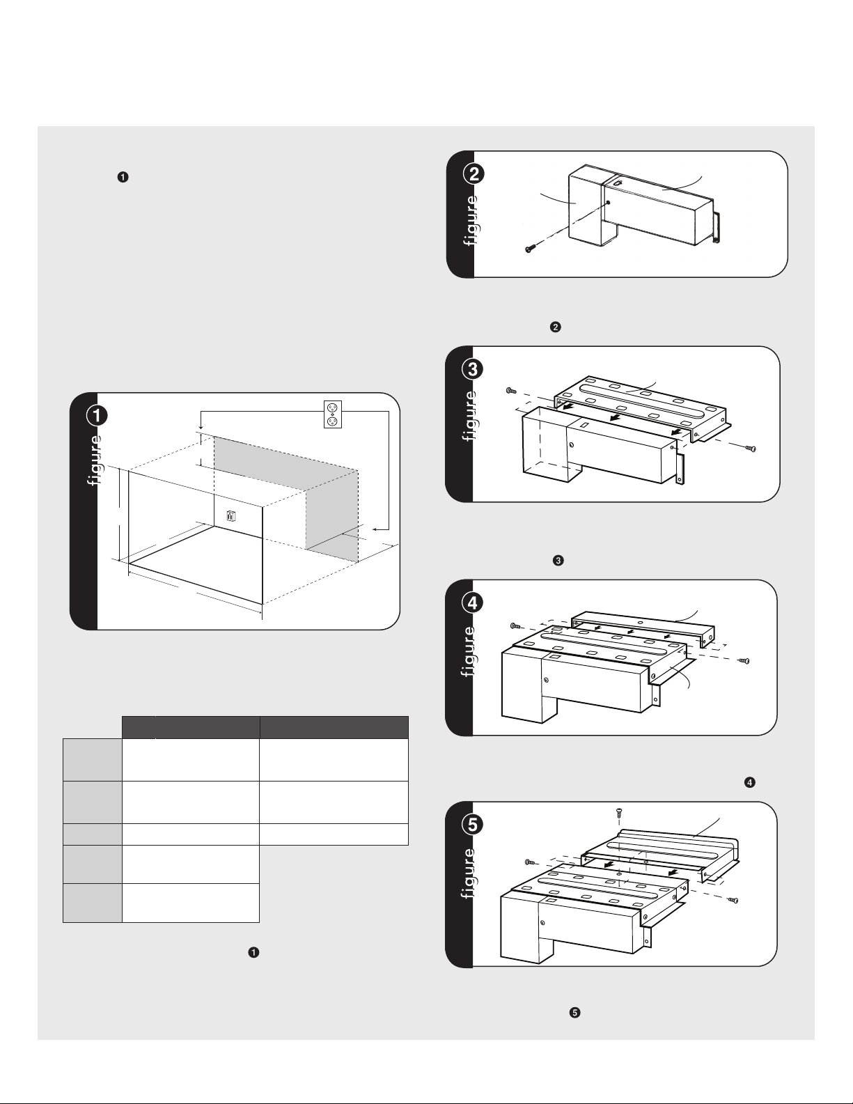
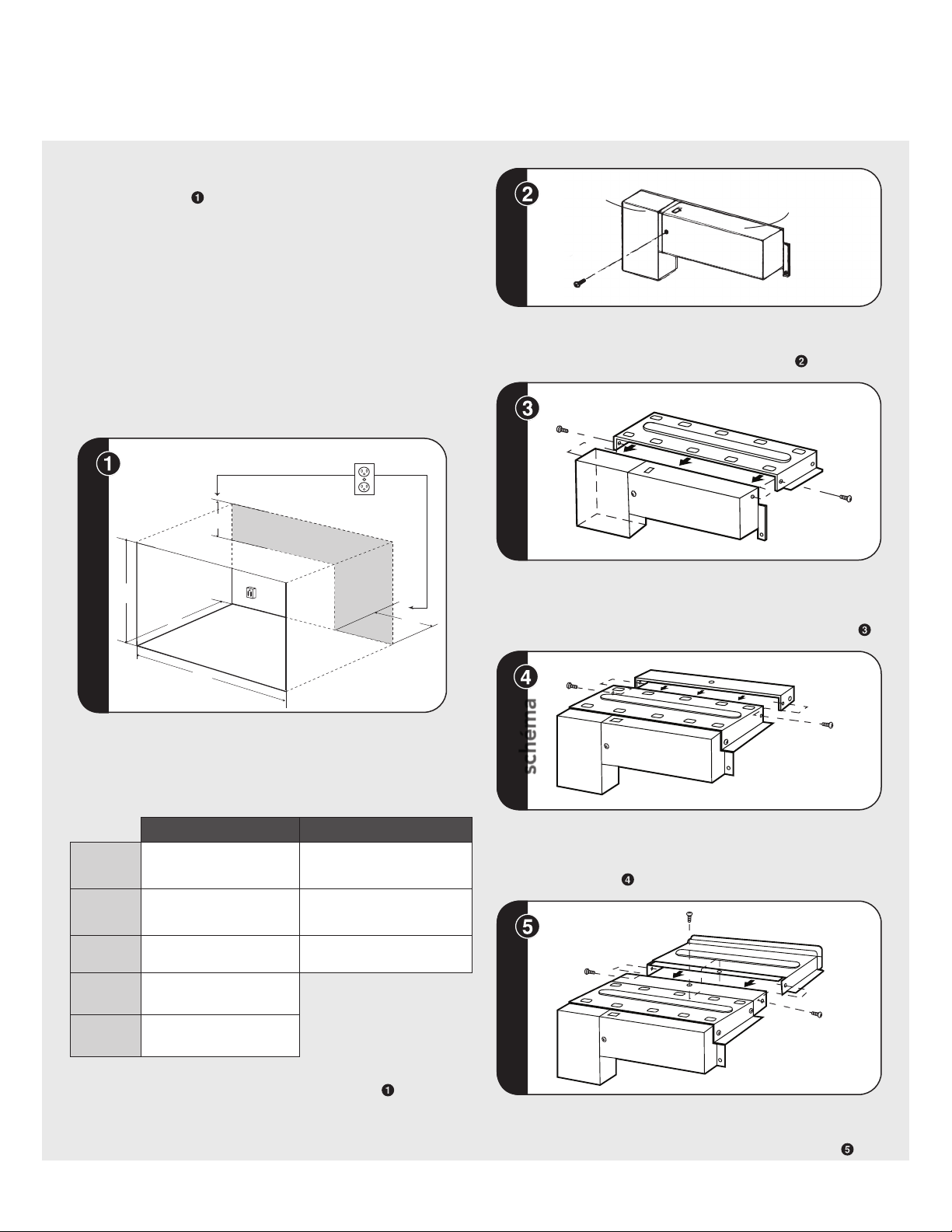
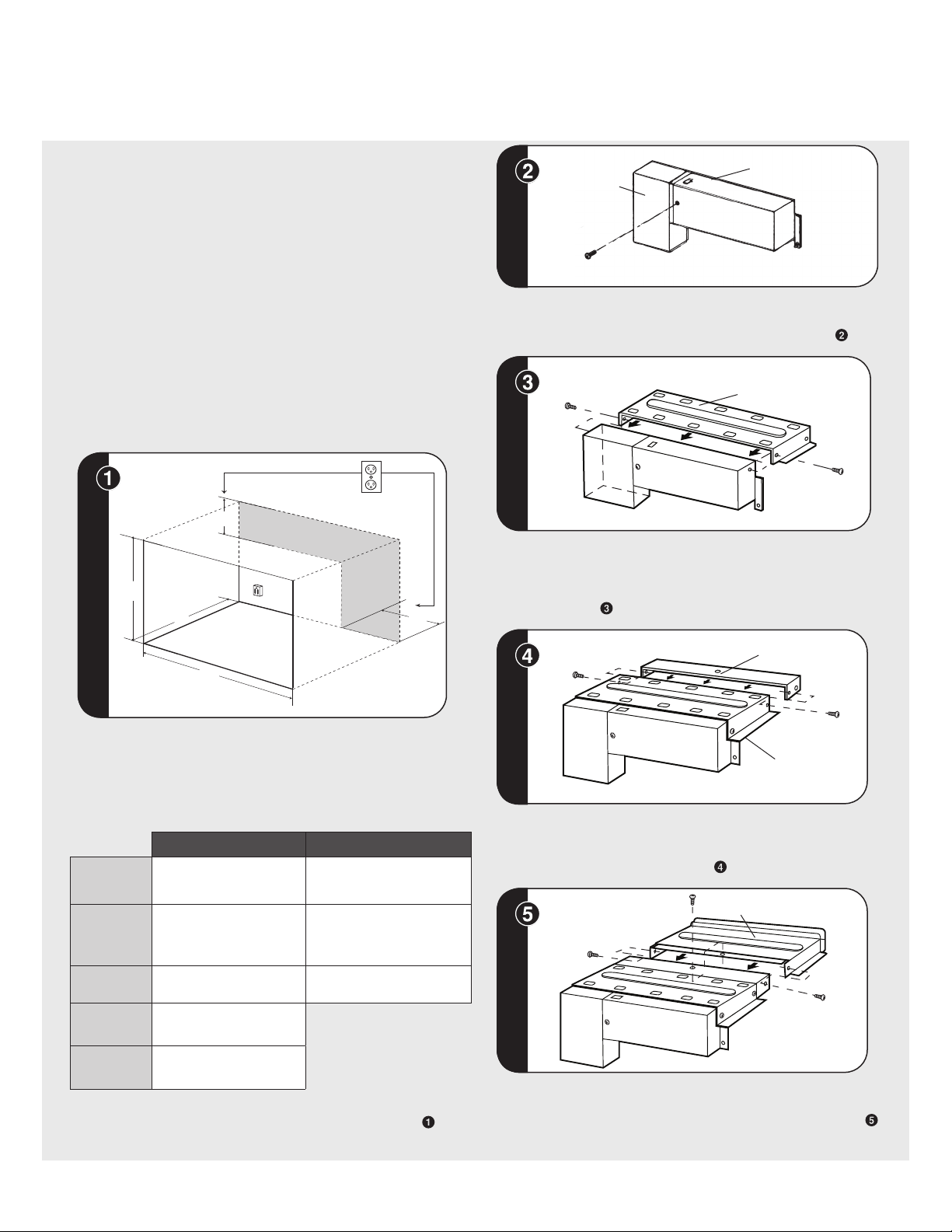
Cabinet or Wall Cutout
Provide an opening in the wall or cabinet as indicated
in gure . The depth should be a minimum of 20-1/8"
(51.1 cm). If the Depth (C) dimension is greater than 21"
(53.3 cm), the outlet location may be in any area on the
rear wall. The oor of the opening should be constructed
of plywood strong enough to support the weight of the
oven (about 100 lbs.) and should be level for proper
operation of the oven.
Note: While the proper functioning of the oven does not
require that the opening be enclosed (with sides, ceiling
and rear partition), this may be required by local code,
and it is suggested that the local code be checked for
any such requirement.
A
B
D
E
C
Surface Mount Cutout Dimensions
* For ush mount dimensions please see installation template and
FLUSH MOUNT INSTALLATION on page 5-6.
CONVECTION CONVENTIONAL
(A) Height
18-1/2" (46.9 cm) Min. 16-3/4" (42.5 cm)
Max. 17" (43.2 cm)
(B) Width
25" (63.5 cm) Min. 24-3/8" (61.9 cm)
Max. 24-11/16" (62.7 cm)
(C) Depth Min. 20-1/8" (51.1 cm) Min. 20-1/8" (51.1 cm)
(D)
Min.
Max.
6"
11-1/2"
(15.2 cm)
(29.2 cm)
(E)
Min.
Max.
4"
5"
(10.2 cm)
(12.7 cm)
ELECTRICAL OUTLET LOCATION: Outlet should NOT be in the
shaded area as indicated on gure . At the rear of the opening,
provide a 3-pronged, polarized, electrical outlet, 115-120 volt AC,
15 amp or larger.
DUCT (C)
DUCT (B)
SCREW (A)
EXHAUST DUCT ASSEMBLY: Insert the edge of DUCT (B) into the
hold lip of DUCT (C). Secure together by using a SCREW (A) provided
in the kit. See gure .
SCREW (A)
DUCT (A)-1
DUCT (BC)
SCREW (A)
EXHAUST DUCT ASSEMBLY: Position DUCT (A)-1 on the top of the
oven inserting edge of DUCT (BC) assembly into hole lip of DUCT
(A)-1. Tighten two SCREWS (A), securing DUCT (A)-1 to DUCT (BC)
assembly. See gure
.
SCREW (A)
SCREW (A)
DUCT (A)-2
DUCT (A)-1
EXHAUST DUCT ASSEMBLY: Position DUCT (A)-2 on the top of the
oven and insert it into the hold lip of DUCT (A)-1. Secure DUCT (A)-2
to DUCT (A)-1 using two SCREWS (A) provided. See gure .
SCREW (A)
SCREW (A)
SCREW
(A)
DUCT (A)-3
DUCT (A)-2
EXHAUST DUCT ASSEMBLY: Position DUCT (A)-3 on top of the oven
and insert it into DUCT (A)-2. Secure DUCT (A)-3 using three screws
(A) provided. See gure .
Exhaust Duct Assembly
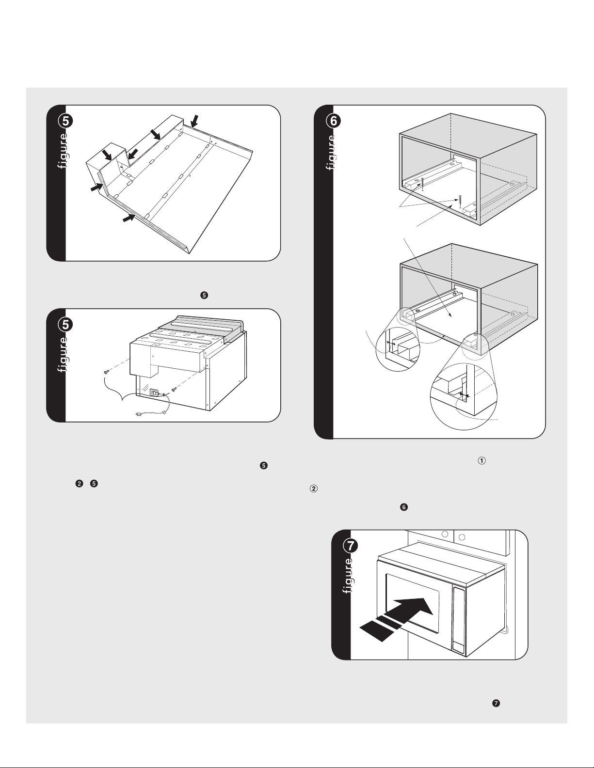
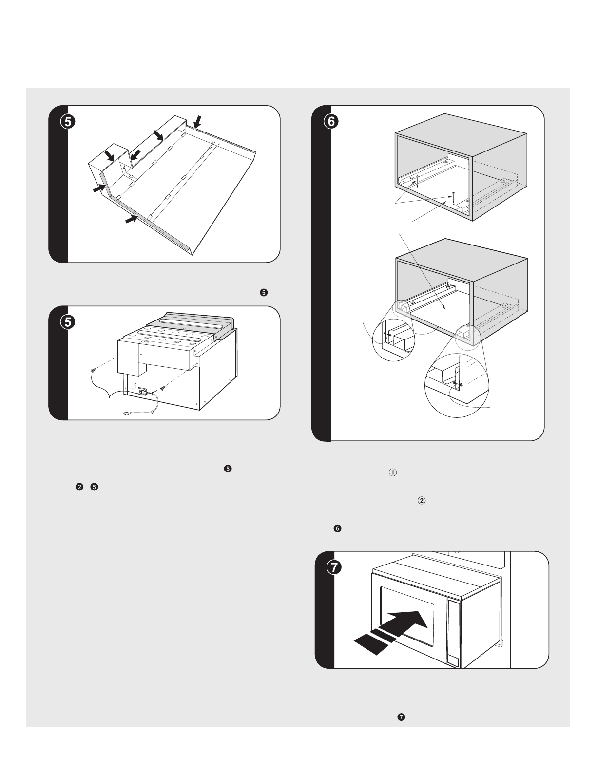
4 E
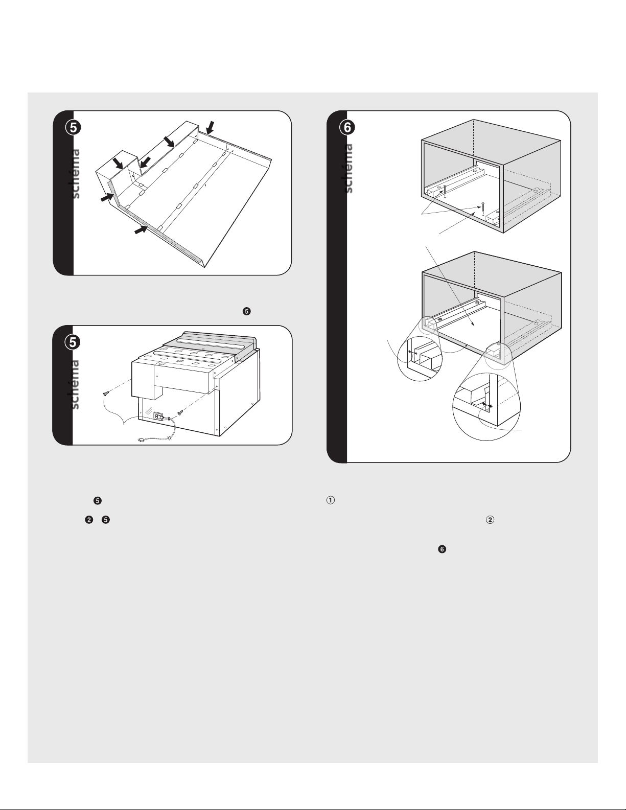
EXHAUST DUCT ASSEMBLY: Remove the cushions from the adhesive
backing. The cushion should be applied to the anges of the duct
assembly as indicated by arrows. See gure A.
B
EXHAUST DUCT ASSEMBLY: Remove SCREW from the upper right
and left corners at the rear of the oven. Place duct assembly on the
top of the unit as shown and secure the duct assembly to the oven
using the two screws just removed from the oven. See gure B.
*Figures - for models VMTK277, 307 and 367 ONLY.
MOUNTING TEMPLATE: Identify the appropriate side of template
to use with your unit. Align the mounting template center line with
the center of the cutout and the oor line with the oor of the cutout.
Tape it into place.
• For VMTK272 only, predrill
4 holes marked “A” with a
1/16" drill bit.
• For VMTK277 only, predrill
4 holes marked “A” with a
1/16" drill bit.
• For VMTK302 only, predrill
4 holes marked “B” with a
1/16" drill bit.
• For VMTK307 only, predrill
4 holes marked “B” with a
1/16" drill bit.
• For VMTK362 only, predrill
4 holes marked “C” with a
1/16" drill bit.
• For VMTK367 only, predrill
4 holes marked “C” with a
1/16" drill bit.
Remove template from the cabinet.
A
Exhaust Duct Assembly Surface Installation
NOTE: CENTER
BOTTOM DUCT
ASSEMBLY IN THE
OPENING
DETAIL A
GAP "B"
BOTTOM DUCT ASSEMBLY
SCREW C
BOTTOM DUCT ASSEMBLY: Place the Bottom Duct in the center of
the opening so that gap "A" is equal to gap "B". When the Bottom
Duct Assembly for VMTK277SS, 307SS or 376SS is positioned properly,
the front edge of the duct will be ush with the front of the cabinet.
The VMTK272SS, 302SS, 372SS Exhaust Duct will be positioned
properly when the edge of the duct is recessed 5mm from the front
of the cabinet. See gure . Secure the Bottom Duct Assembly with
the two (¾") SCREWS (C).
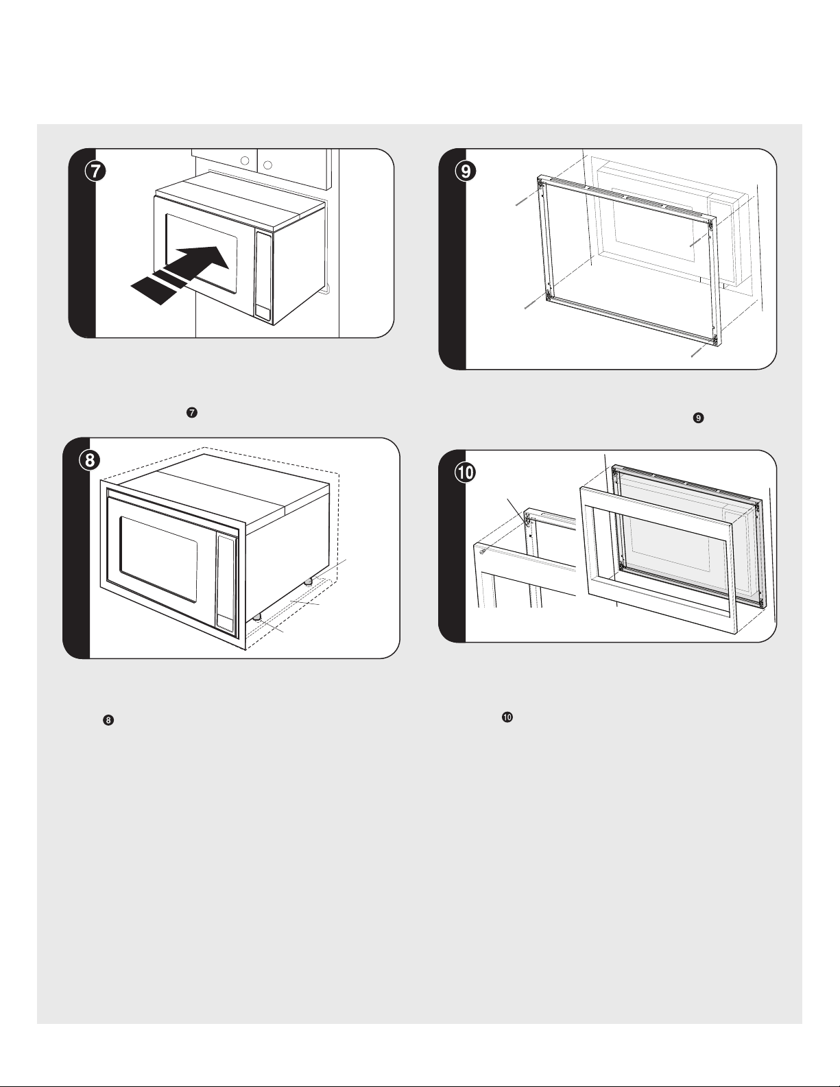
CABINET INSTALLATION: Place the oven adjacent to the wall or
cabinet opening. Plug the power cord into the electrical outlet.
Carefully guide the assembled oven into the prepared opening. Slide
the oven on the Bottom Duct Assembly. See gure .
SCREW
GAP "A"
5E
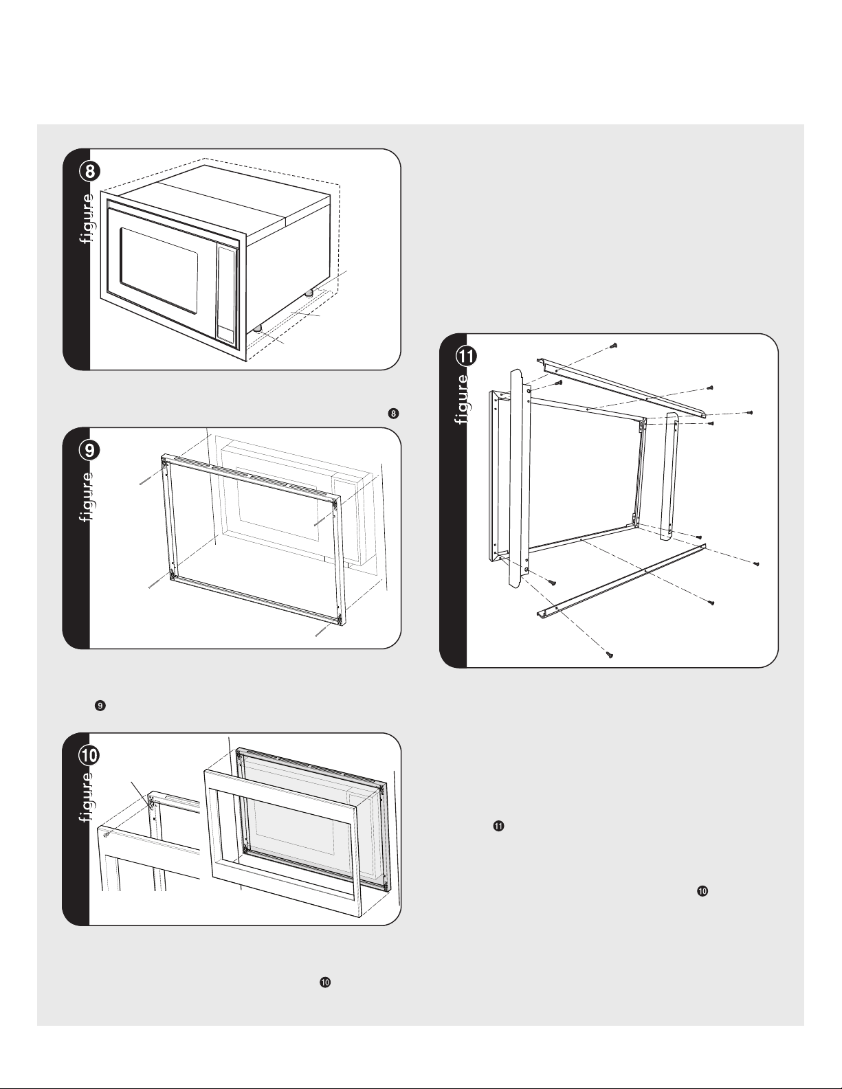
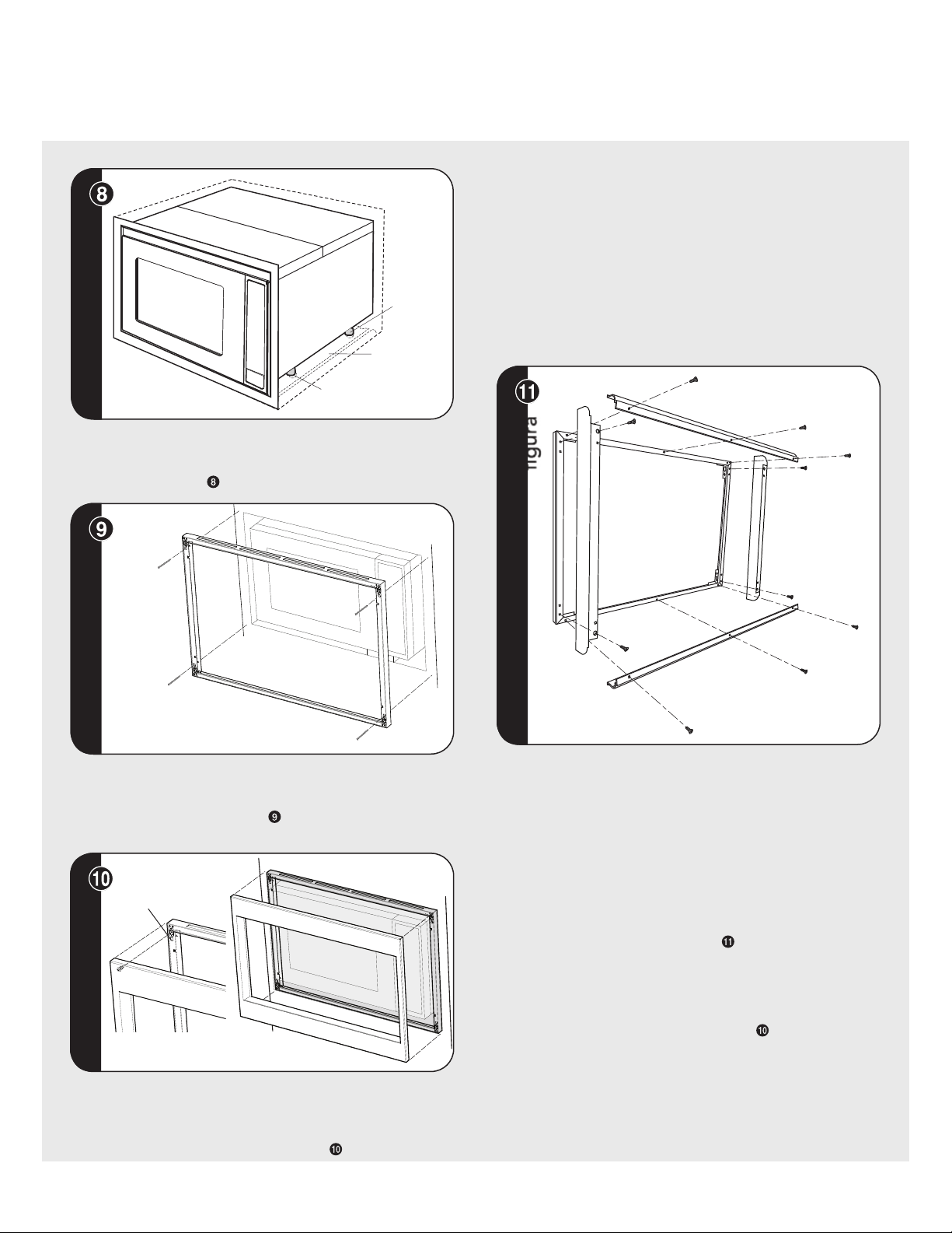
Surface Installation Flush Mount Installation
DUCT RECESS
BOTTOM
DUCT
ASSEMBLY
FOOT
CABINET INSTALLATION: Avoid pinching the cord between the oven
and the wall. Adjust the position of the oven so that the feet of the oven
are tted into the holes of the Bottom Duct Assembly. See gure .
SCREW (B)
SCREW (B)
SCREW (B)
SCREW (B)
FRAME INSTALLATION: Position the BACK FRAME to align with
the predrilled holes that were drilled with the mounting template.
Check that it is level and then secure with four SCREWS (B). See
gure . Secure the bottom portion of the BACK FRAME with the
two remaining SCREWS (B).
SNAP
ATTACHMENT
DECORATION INSTALLATION: Place the FRONT decoration onto the
FRAME and align ball studs and receivers. Secure the DECORATION
to the FRAME by rmly pushing the front frame onto the back frame
engaging the four (4) snap attachments. See gure .
PARTS INCLUDED IN FLUSH MOUNT ACCESSORY KIT
(PURCHASED SEPARATELY):
• (2) Stainless Steel Scoops
• (10) Stainless Machine Screws
• (1) Flush Mount Template
• (2) Side Trim
* See FLUSH MOUNT TEMPLATE for additional installation
instructions.
FLUSH MOUNT INSTALLATION: Place the 2 Scoops on the back of
the frame as shown and align the screw holes on the scoop with the
tapped holes in the frame. Secure the scoops to the frame using 6
of the machine screws provided in the kit. Place the side trim pieces
on the back of the frame as shown and align the top and bottom
most screw holes with the corresponding taped holes in the frame.
Secure the trim pieces with the 4 remaining machine screws provided.
Attach the frame assembly to the wooden side spacers by aligning
the mounting holes in the frame with the pre-drilled holes in the
side spacers and secure with SCREW (B) provided with the trim kit.
See gure .
DECORATION INSTALLATION: Place the FRONT decoration onto the
FRAME and align ball studs and receivers. Secure the DECORATION
to the FRAME by rmly pushing the front frame onto the back frame
engaging the four (4) snap attachments. See gure .
6 E
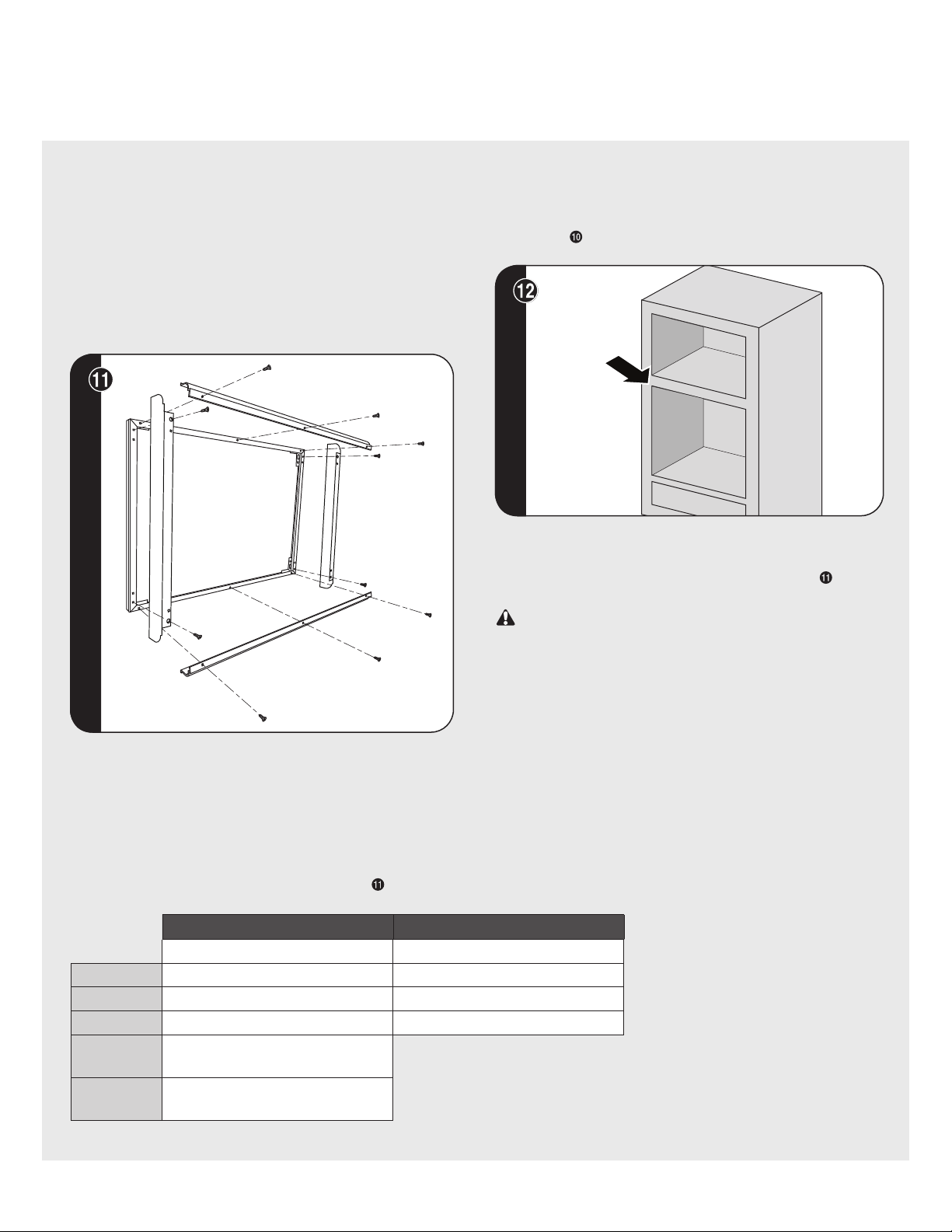
MICROWAVE
OPENING
LOWER OVEN
OPENING
OVER OVEN INSTALLATION: Space between the microwave and the
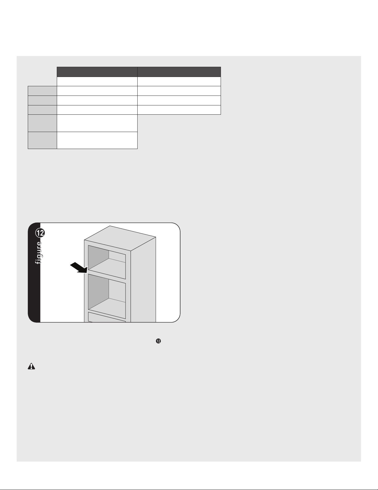
lower oven: 2" (5.08 cm) for 27"W and 30"W. See Figure .
For more product information,
call 1-888-845-4641
Installation
The trim kits described in this installation guide, and listed
below, are NOT TO BE INSTALLED ABOVE GAS OVENS.
VMTK272SS VMTK307SS VMTK362SS
VMTK277SS VMTK302SS VMTK367SS
Flush Mount Installation
CONVECTION CONVENTIONAL
30" 30"
(A) Height 21-5/16" (542 cm) 19-7/8" (504 cm)
(B) Width 29-15/16" (76 cm) 29-15/16" (76 cm)
(C) Depth 22-1/16" (56.1 cm) 22-1/16" (56.1 cm)
(D)
Min.
Max.
6"
11-1/2"
(15.2 cm)
(29.2 cm)
(E)
Min.
Max.
4"
5"
(10.2 cm)
(12.7 cm)

Guide d’installation
Kit de garniture à encastrer pour four à
micro-ondes
F
1 F
IMPORTANT–Prière de Lire et de Suivre !
• Prière de lire attentivement toutes ces directives avant de commencer.
• Veiller à DÉBRANCHER LA FICHE du four à micro-ondes de la prise électrique avant d’installer la garniture à encastrer. Retirer
la table tournante de la cavité du four.
• Le kit comprend des parties métalliques, il faut faire attention lors de la manipulation et de l’installation pour éviter éventuelles
blessures.
• Ne pas retirer de façon permanente les étiquettes, les mises en garde ou les plaques xées au produit. Cela pourrait annuler
la garantie.
• Veuillez observer tous les codes et règlements locaux et national.
• L’installateur devra laisser ces directives au client qui devra les conserver pour l’usage d’un inspecteur local et pour
référence ultérieure.
• Ce kit à encastrer est destiné à être utilisé UNIQUEMENT AVEC LES FOURS À MICRO-ONDES TRADITIONNELS ET À
CONVECTION SPÉCIFIANT KIT À ENCASTRER VMTK272, VMTK302, VMTK362, VMTK277, VMTK307 ou VMTK367 sur
l'étiquette des spécications nominales présente sur la plaque frontale inférieure de la cavité du four.
• VOTRE FOUR PEUT ÊTRE INTÉGRÉ DANS UNE ARMOIRE OU LE MUR LUI-MÊME OU PAR-DESSUS TOUT FOUR ÉLECTRIQUE
OU AU MUR OU LE TIROIR DE RÉCHAUFFEMENT.
Minimum Cutout Opening Width 24-3/8" (619.13 mm)
Maximum Cutout Opening Width 24-11/16" (627.06 mm)
Minimum Cutout Opening Height 16
-
3/4" (425.5 mm)
Maximum Cutout Opening Height 17" (431.8 mm)
Maximum Height distance between holes 14-1/4" (361.825 mm)
Distance between centerline to holes
12-13/16" (324.65 mm)
Distance between holes A 25-9/16" (649.3 mm)
Distance between centerline to holes
14-5/16" (362.75 mm)
Distance between holes B 28-9/16" (725.5 mm)
15-13/32" (391.45 mm)
Center Line
BUILT-IN TRIM KIT TEMPLATE
FOR CUSTOM SERIES MICROWAVE OVEN
1. Align the mounting template center line with the center of the cutout
and the floor line with the floor of the cutout. Tape it into place.
2. For VMTK272, predrill 4 holes marked A with a 1/16" drill bit.
For VMTK302, predrill 4 holes marked B with a 1/16" drill bit.
3. Remove template from the cabinet.
TINSKB182MRR0
Floor Line of Cutout Opening
USE THIS SIDE OF TEMPLATE FOR MODELS
VMTK272 and VMTK302 ONLY.
1-5/32"
(29.6 mm)
Pièces Comprises dans le Kit VMTK
Châssis avant
QTÉ 1
Châssis arrière
QTÉ 1
Ensemble du châssis QTÉ 1
Ensemble du conduit inférieur QTÉ1 *
Vis A (1/2 po longueur)
QTÉ 10 *
Vis B (1-3/4 po
longueur) QTÉ 4
Gabarit à montage en surface
2 faces de 27 & 30 po
ou gabarit à montage en
surface simple face de 36 po
QTÉ 1
Coussin QTY 6 *
Conduit (A)-1 QTÉ 1 *
Conduit (A)-3 QTÉ1 *
Conduit (B) QTÉ 1 *
*
Conduit (C) QTÉ 1 *
Conduit (A)-2 QTÉ1 *
Vis
C (3/4 po longueur)
QTÉ 2
*VMTK277, VMTK307 et VMTK367 UNIQUEMENT.
2F
Spécifications de Base
Four à micro-ondes Kits de garniture à encastrer
Descriptión CONVECTION VMOC206SS/VMOC506SS VMTK277 VMTK307
Largeur hors tout 24-5/8 po (62,5 cm) 26-1/2 po (67,3 cm) 29-1/2 po (74,9 cm)
Hauteur hors tout
depuis le bas
14-7/8 po (37,7 cm) 19-13/16 po (50,1 cm) 19-13/16 po (50,1 cm)
Profondeur hors
tout depuis
l’arrière
19 po (48,3 cm) S/O
Intérieur du four
Largeur
Hauteur
Profondeur
Total
16-1/8 po
9-5/8 po
16-1/8 po
1,5 cu. ft.
(40,9 cm)
(24,4 cm)
(40,9 cm)
S/O
Largeur de la
découpe
S/O
Min.
Max.
25 po
25-3/8 po
(63,5 cm)
(64,5 cm)
Hauteur de la
découpe
S/O
18-11/16 po (46,9 cm)
Profondeur de la
découpe
S/O
Min.
Max.
20-1/8
po
S/O
(51,1 cm)
S/O
Alimentation
électrique
120VAC/60 Hz (UL)
117VAC/60 Hz (CSA)
S/O
Ampèrage max.
1,55 KW
1,5 KW
13 amps (UL)
13 (CSA)
S/O
Poids approx. à
l’expédition.
60 lbs. (27,2 kg) 19 lbs. (8,6 kg) 20 lbs. (9,1 kg)
Descriptión TRADITIONNEL VMOS201SS/VMOS501SS VMTK272 VMTK302
Largeur hors tout 24 po (60,9 cm) 26-1/2 po (67,3 cm) 29-1/2 po (74,9 cm)
Hauteur hors tout
depuis le bas
13-3/8 po (33,9 cm) 18-1/4 po (46,3 cm) 18-1/4 po (46,3 cm)
Profondeur hors
tout depuis
l’arrière
19-1/4 po (48,9 cm) S/O
Intérieur du four
Largeur
Hauteur
Profondeur
Total
17-3/8 po
10-1/2 po
18-5/8 po
2,0 cu. ft.
(44,1 cm)
(26,6 cm)
(47, 3 c m)
S/O
Largeur de la
découpe
S/O
Min.
Max.
24-3/8 po
24-11/16 po
(61,9 cm)
(62,7 cm)
Hauteur de la
découpe
S/O
Min.
Max.
16-3/4 po
17 po
(42,5 cm)
(43,2 cm)
Profondeur de la
découpe
S/O
Min.
Max.
20 po
S/O
(50,3 cm)
S/O
Alimentation
électrique
120VAC/60 Hz S/O
Ampèrage max. 1,5 KW 13 amps S/O
Poids approx. à
l’expédition.
46 lbs. (20,9 kg) 14 lbs. (6,5 kg) 15 lbs. (6,9 kg)
3 F
Découpe de l’armoire ou du mur
Faire une ouverture dans le mur ou l’armoire comme
indiqué à schéma . La profondeur doit être au minimum
de 20-1/8 po (51,1 cm). Si la profondeur (C) dépasse 21
po (53,3 cm), l'emplacement de la prise peut être situé
n'importe où sur le mur arrière. Le plancher de l’ouverture
doit être en contreplaqué assez fort pour supporter le
poids du four et sa propre charge (environ 45,5 Kg [100
lb]). Il doit être à un niveau convenable pour l’utilisation
du four.
Remarque : Bien que le bon fonctionnement du four ne
demande pas que l’ouverture soit close (avec cloisons
latérales, arrière et plafond), le code local pourrait
l’exiger; il est donc suggérer de vérier ce point.
schéma
schéma
A
B
D
E
C
Dimensions de la découpe pour montage en surface
* Pour les dimensions relatives au montage encastré, veuillez
vous reporter au gabarit d'installation et à INSTALLATION POUR
MONTAGE ENCASTRÉ à la page 6.
CONVECTION TRADITIONNEL
(A)
Hauteur
18-1/2 po (46,9 cm) Min. 16-3/4 po (42,5 cm)
Max. 17" (43,2 cm)
(B) Largeur
25 po (63,5 cm) Min. 24-3/8 po (61,9 cm)
Max. 24 -11/16 po (62,7 cm)
(C)
Profondeur
Min. 20-1/8 po (51,1 cm) Min. 20-1/8 po (51,1 cm)
(D)
Min.
Max.
6 po
11-1/2 po
(15,2 cm)
(29,2 cm)
(E)
Min.
Max.
4"
5"
(10,2 cm)
(12,7 cm)
EMPLACEMENT DE LA PRISE ÉLECTRIQUE : La prise NE doit PAS
se trouver dans l’aire ombrée comme indiqué à schéma
. À l’arrière
de l’ouverture, installer une prise électrique polarisée pour che à
trois broches, 115-120 volt CA, 15 A ou plus.
CONDUIT (C)
CONDUIT
(B)
VIS (A)
schéma
schéma
ENSEMBLE DU CONDUIT D’ÉVACUATION : Insérer le bord du
CONDUIT (B) dans le joint à lèvre du CONDUIT (C). Les xer ensemble
à l’aide d’une VIS (A) fournis dans le kit. Voir schéma .
VIS (A)
CONDUIT (A)-1
CONDUIT (BC)
VIS (A)
schéma
schéma
ENSEMBLE DU CONDUIT D’ÉVACUATION : Placer le CONDUIT (A)-1
au dessus du four en insérant le bord de l’ensemble du CONDUIT
(BC) dans la lèvre du CONDUIT (A)-1. Serrer deux VIS (A) pour xer
le CONDUIT (A)-1 à l’ensemble du CONDUIT (BC). Voir schéma .
VIS (A)
VIS (A)
CONDUIT
(A)-2
CONDUIT
(A)-1
schéma
ENSEMBLE DU CONDUIT D’ÉVACUATION : Placer le CONDUIT (A)-2
au dessus du four et l’insérer dans le joint à lèvre du CONDUIT (A)-1.
Fixer le CONDUIT (A)-2 au CONDUIT (A)-1 à l’aide de deux VIS (A)
fournies. Voir schéma
.
VIS (A)
VIS (A)
VIS (A)
CONDUIT
(A)-3
CONDUIT
(A)-2
schéma
schéma
ENSEMBLE DU CONDUIT D’ÉVACUATION : Placer le CONDUIT
(A)-3 au dessus du four et l’insérer dans le CONDUIT (A)-2. Fixer le
CONDUIT (A)-3 à l’aide de trois vis (A) fournies. Voir schéma .
Ensemble du conduit d’évacuation
4F
Ensemble du conduit
d’évacuation
Installation en surface
schéma
A
ASSEMBLAGE DU CONDUIT D'ÉVACUATION : Retirer les coussins
du support adhésif. Appliquer les coussins aux brides de l'ensemble
conduit comme indiqué par les èches. Voir schéma A.
B
schéma
VIS
ASSEMBLAGE DU CONDUIT D'ÉVACUATION : Retirer la VIS des
coins supérieurs droit et gauche à l'arrière du four. Placer l'ensemble
conduit au-dessus de l'appareil comme illustré et xer l'ensemble
conduit sur le four à l'aide des deux vis qui viennent d'être retirées.
Voir schéma B.
*Schémas à les modèles VMTK277, 307 et 367 UNIQUEMENT.
GABARIT DE MONTAGE : Déterminer le côté du gabarit qu'il convient
d'utiliser avec votre appareil. Aligner la ligne centrale du gabarit de
montage avec le centre de la découpe et la ligne de plancher avec
le plancher de la découpe. Coller en place avec du ruban adhésif.
• Pour VMTK272 uniquement,
percer les 4 trous marqués «
A » avec un foret de 1/16 po
(1,6 mm).
• Pour VMTK277 uniquement,
percer les 4 trous marqués «
A » avec un foret de 1/16 po
(1,6 mm).
• Pour VMTK302 uniquement,
percer les 4 trous marqués «
B » avec un foret de 1/16 po
(1,6 mm).
• Pour VMTK307 uniquement,
percer les 4 trous marqués «
B » avec un foret de 1/16 po
(1,6 mm).
• Pour VMTK362 uniquement,
percer les 4 trous marqués «
C » avec un foret de 1/16 po
(1,6 mm).
• Pour VMTK367 uniquement,
percer les 4 trous marqués «
C » avec un foret de 1/16 po
(1,6 mm).
Enlever le gabarit de l’armoire.
REMARQUE:
ENSEMBLE
DU CONDUIT
INFÉRIEUR
CENTRAL
DÉTAIL A
ÉCART "B"
ENSEMBLE DU CONDUIT D’ÉVACUATION
VIS C
schéma
ENSEMBLE DU CONDUIT D’ÉVACUATION : Placer le conduit inférieur
au centre de l’ouverture an que l’écart “A” soit égal à l’écart “B”.
Quand l’ENSEMBLE DU CONDUIT INFÉRIEUR pour VMTK277SS,
307SS ou 376SS est placé correctement, les brides seront serrées
contre la bordure inférieure de l’ouverture. Le VMTK272SS, 302SS
et 372SS conduits d'échappement sera est placé correctement quand
le bord du conduit est encastré de 5 mm à partir la bordure inférieure
de l’ouverture. Voir schéma . Fixer l’ENSEMBLE DU CONDUIT
INFÉRIEUR avec deux (¾ po) VIS (C) pour les modèles VMTK302SS,
VMTK362SS, VMTK307SS et VMTK367SS et utiliser les deux (1-3/16
po) (A) pour les modèles VMTK272 et VMTK277.
IMPORTANT: Fixer les vis à l’aide des trous dans la bride inférieure.
ÉCART "A"
5 F
Installation en surface
schéma
schéma
POSE DANS L’ARMOIRE : Placer le four près de l’ouverture du mur
ou de l’armoire. Brancher le cordon d’alimentation dans la prise
électrique. Guider avec précaution le four assemblé dans l’ouverture
préparée. Faire glisser le four sur l’ENSEMBLE DU CONDUIT
INFÉRIEUR. Voir schéma .
ÉVIDEMENT DANS LE
CONDUIT
ENSEMBLE
DU CONDUIT
INFÉRIEUR
PATTE
schéma
schéma
POSE DANS L’ARMOIRE : Éviter de pincer le cordon entre le four et le
mur. Ajuster la position du four de façon à ce que ses pattes entrent
dans les évidements de l’ENSEMBLE DU CONDUIT INFÉRIEUR. Voir
schéma .
VIS (B)
VIS (B)
VIS (B)
VIS (B)
schéma
schéma
INSTALLATION DU CHÂSSIS : Placer le CHÂSSIS ARRIÈRE pour qu’il
soit aligné avec les trous percés à l’aide du gabarit. Vérier qu’il est de
niveau puis le xer avec quatre VIS (B). Voir schéma . Fixer la partie
inférieure de l’ENSEMBLE DU CHÂSSIS avec deux VIS (B) restantes.
FIXATION À
RESSORT
schéma
schéma
INSTALLATION DE LA DÉCORATION : Placer la décoration AVANT
sur le CADRE et aligner les pivots à rotule avec les récepteurs. Fixer
la DÉCORATION sur le CADRE en poussant fermement le cadre avant
sur le cadre arrière en engageant les quatre (4) xations à pression.
Voir schéma .
6F
PIÈCES INCLUSES DANS LE KIT D'ACCESSOIRES DE
MONTAGE ENCASTRÉ (ACHETÉ SÉPARÉMENT) :
• (2) Boules en acier inoxydable
• (10) Vis à métaux inoxydables
• (1) Gabarit de montage encastré
• (2) Garnitures latérales
* Voir GABARIT DE MONTAGE ENCASTRÉ pour obtenir des
instructions d'installation complémentaires.
schéma
schéma
INSTALLATION DU MONTAGE ENCASTRÉ : Placer les 2 ouïes de
ventilation à l'arrière du cadre comme illustré et aligner les trous de
vis de l'ouïe avec les trous taraudés du cadre. Fixer les ouïes sur le
cadre avec les 6 vis à métaux fournies dans le kit. Placer les garnitures
latérales à l'arrière du cadre comme illustré et aligner les trous des vis
du haut et du bas avec les trous taraudés correspondants sur le cadre.
Fixer les garnitures avec les 4 vis à métaux restantes. Fixer le cadre
de porte sur les entretoises latérales en bois en alignant les trous de
montage sur le cadre avec les avant-trous sur les entretoises latérales
et serrer avec la VIS (B) incluse dans le kit. Voir gure .
INSTALLATION DE LA DÉCORATION : Placer la décoration AVANT
sur le CADRE et aligner les pivots à rotule avec les récepteurs. Fixer
la DÉCORATION sur le CADRE en poussant fermement le cadre avant
sur le cadre arrière en engageant les quatre (4) xations à pression.
Voir schéma
.
DÉCOUPE POUR
LE MICRO-
ONDES
DÉCOUPE
DU FOUR
INFÉRIEUR
schéma
schéma
INSTALLATION AU DESSUS D’UN FOUR : L'espace entre les micro-
ondes et le four inférieur: 5,08 cm (2 po) pour un four inférieur de
68,6 cm (27 po) et 76,2 cm (30 po) de large. Voir schéma .
Pour plus d’information sur le produit,
appeler au 1-888-845-4641
Installation
Les kits à encastrer décrits dans ce guide d'installation, et
indiqués ci-dessous, NE DOIVENT PAS ÊTRE INSTALLÉS
AU-DESSUS DE FOURS À GAZ.
VMTK272SS VMTK307SS VMTK362SS
VMTK277SS VMTK302SS VMTK367SS
Installation du montage encastré
CONVECTION TRADITIONNEL
30 po 30 po
(A) Hauteur 21-5/16 po (542 cm) 19-7/8 po (504 cm)
(B) Largeur 29-15/16 po (76 cm) 29-15/16 po (76 cm)
(C) Profondeur 22-1/16 po (56,1 cm) 22-1/16 po (56,1 cm)
(D)
Min,
Max,
6 po
11-1/2 po
(15,2 cm)
(29,2 cm)
(E)
Min,
Max,
4 po
5 po
(10,2 cm)
(12,7 cm)

Instrucciones de Instalación
Juego de Molduras para Empotrado
para Horno Microondas
S

1S 1
IMPORTANTE - Lea y siga las instrucciones
• Antes de comenzar, lea estas instrucciones completa y detalladamente.
• Asegúrese de DESCONECTAR el horno microondas del tomacorriente eléctrico antes de instalar el juego de moldura para
empotrado. Retire el plato giratorio de la cavidad del horno.
• El juego incluye partes de metal por lo que debe manipularlo e instalarlo con precaución para evitar el riesgo de lesiones.
• No retire las etiquetas, advertencias o placas permanentes del producto. Esto puede anular la garantía.
• Cumpla todos los códigos y normas locales y nacionales.
• El instalador debe devolver estas instrucciones al cliente quien debe conservarlas para uso del inspector local y para
referencias futuras.
• Este juego de molduras para empotrado está diseñado para usarlo SÓLO CON HORNOS MICROONDAS DE CONVECCIÓN
Y CONVENCIONALES QUE ESPECIFIQUEN EL JUEGO DE MOLDURAS PARA EMPOTRADO VMTK272, VMTK302, VMTK362,
VMTK277, VMTK307 o VMTK367 en la etiqueta de potencia en la placa de la parte inferior de la cavidad del horno.
• EL HORNO PUEDE SER CONSTRUIDO EN UN GABINETE O EN LA PARED POR SÍ MISMO O POR ENCIMA DE CUALQUIER
HORNO DE PARED ELÉCTRICO O EL CAJÓN CALENTADOR.
Minimum Cutout Opening Width 24-3/8" (619.13 mm)
Maximum Cutout Opening Width 24-11/16" (627.06 mm)
Minimum Cutout Opening Height 16
-
3/4" (425.5 mm)
Maximum Cutout Opening Height 17" (431.8 mm)
Maximum Height distance between holes 14-1/4" (361.825 mm)
Distance between centerline to holes
12-13/16" (324.65 mm)
Distance between holes A 25-9/16" (649.3 mm)
Distance between centerline to holes
14-5/16" (362.75 mm)
Distance between holes B 28-9/16" (725.5 mm)
15-13/32" (391.45 mm)
Center Line
BUILT-IN TRIM KIT TEMPLATE
FOR CUSTOM SERIES MICROWAVE OVEN
1. Align the mounting template center line with the center of the cutout
and the floor line with the floor of the cutout. Tape it into place.
2. For VMTK272, predrill 4 holes marked A with a 1/16" drill bit.
For VMTK302, predrill 4 holes marked B with a 1/16" drill bit.
3. Remove template from the cabinet.
TINSKB182MRR0
Floor Line of Cutout Opening
USE THIS SIDE OF TEMPLATE FOR MODELS
VMTK272 and VMTK302 ONLY.
1-5/32"
(29.6 mm)
Partes incluidas en los juegos VMTK
Marco frontal
CANT. 1
nuevo marco de
CANT. 1
Conjunto del marco CANT. 1
Conjunto de ducto inferior CANT. 1
Tornillo A (1/2" de largo)
CANT. 10 *
Tornillo B (1-3/4" de
largo)
CANT. 4
Plantilla para montaje en supercie
de dos caras de 27" y 30"
o plantilla para montaje en
supercie de una cara de 36"
CANT. 1
*
Cojín
CANT. 6 *
Ducto (A)-1 CANT. 1 * Ducto (A)-3 CANT. 1 *
Ducto (B) CANT. 1 *
Ducto (C) CANT. 1 *
Ducto (A)-2 CANT. 1 *
Tornillo C (3/4" de largo)
CANT. 2
*SÓLO VMTK277, VMTK307 y VMTK367.
2 S2
Especificaciones Básicas
Horno Microondas Juego de Molduras para Empotrado
Descripción CONVECCIÓN VMOC206SS/VMOC506SS VMTK277 VMTK307
Ancho total 24-5/8" (62.5 cm) 26-1/2" (67.3 cm) 29-1/2" (74.9 cm)
Altura total
desde la parte
inferior
14-7/8" (37.7 cm) 19-13/16" (50.1 cm) 19-13/16" (50.1 cm)
Profundidad total
desde la parte
posterior
19" (48.3 cm) N/A
Parte interna del
horno
Ancho
Altura
Profun.
Total
16-1/8"
9-5/8"
16-1/8"
pies
cúbicos
(40.9 cm)
(24.4 cm)
(40.9 cm) N/A
Ancho de recorte
N/A
Mín.
Máx.
25"
25 -3/8"
(63.5 cm)
(64.5 cm)
Altura de recorte N/A 18 -11/16" (46.9 cm)
Profundidad de
recorte
N/A
Mín.
Máx.
20-1/8"
N/A
(51.1 cm)
N/A
Requisitos
eléctricos
120VAC/60 Hz (UL)
117VAC/60 Hz (CSA)
N/A
Cap. máx. en
amperios
1.55 KW
1.5 KW
13 amps (UL)
13 (CSA)
N/A
Peso aproximado
de embarque
60 lbs. (27.2 kg) 19 lbs. (8.6 kg) 20 lbs. (9.1 kg)
Descripción CONVENCIONAL VMOS201SS/VMOS501SS VMTK272 VMTK302
Ancho total 24" (60.9 cm) 26-1/2" (67.3 cm) 29-1/2" (74.9 cm)
Altura total
desde la parte
inferior
13-3/8" (33.9 cm) 18-1/4" (46.3 cm) 18-1/4" (46.3 cm)
Profundidad total
desde la parte
posterior
19-1/4" (48.9 cm) N/A
Parte interna del
horno
Ancho
Altura
Profun.
Total
17-3/8"
10-1/2"
18-5/8"
2.0 pies
cúbicos
(44.1 cm)
(26.6 cm)
(47.3 cm) N/A
Ancho de recorte
N/A
Mín.
Máx.
24-3/8"
24-11/16"
(61.9 cm)
(62.7 cm)
Altura de recorte
N/A
Mín.
Máx.
16-3/4"
17"
(42.5 cm)
(43.2 cm)
Profundidad de
recorte
N/A
Mín.
Máx.
20"
N/A
(50.3 cm)
N/A
Requisitos
eléctricos
120VAC/60 Hz N/A
Cap. máx. en
amperios
1.5 KW 13 amps N/A
Peso aproximado
de embarque
46 lbs. (20.9 kg) 14 lbs. (6.5 kg) 15 lbs. (6.9 kg)
3S 3
Abertura del gabinete o pared
Haga una abertura en la pared o en el gabinete como se
indica en la gura
1
. La profundidad debe tener un mínimo
de 20-1/8" (51.1 cm). Si la dimensión de la profundidad
(C) es mayor a 21" (53.3 cm), la ubicación de la toma
de corriente puede estar en cualquier área de la pared
posterior. La supercie de la abertura debe ser construida
de madera laminada lo sucientemente resistente para
soportar el peso del horno (aproximadamente 100 libras)
y debe ser nivelada para obtener un funcionamiento
adecuado del horno.
Nota: Aunque el correcto funcionamiento del horno
no requiere que la abertura esté cerrada (con tabiques
laterales, superiores y posteriores), el código local puede
exigirlo y se sugiere revisar en el código local alguna
indicación de ese tipo.
A
B
D
E
C
figura
figura
Dimensiones de los recortes para montaje en
supercie
* Para dimensiones de montaje al ras vea la plantilla de instalación y
la INSTALACIÓN DE MONTAJE AL RAS en la página 17-18.
CONVECCIÓN CONVENCIONAL
(A) Altura
18-1/2" (46,9 cm) mín. 16-3/4" (42,5 cm)
máx. 17" (43,2 cm)
(B) Peso
25" (63,5
cm)
mín. 24-3/8" (61,9 cm)
máx. 24-11/16" (62,7 cm)
(C)
Profundidad
mín. 20-1/8" (51,1 cm) mín. 20-1/8" (51,1 cm)
(D)
mín.
máx.
6"
11-1/2"
(15,2 cm)
(29,2 cm)
(E)
mín.
máx.
4"
5"
(10,2 cm)
(12,7 cm)
UBICACIÓN DEL TOMACORRIENTE ELÉCTRICO: El tomacorriente
NO debe estar en el área sombreada como se indica en la gura . En
la parte posterior de la abertura, debe haber un tomacorriente eléctrico
de tres clavijas polarizado de 115-120 volt CA, 15 amperios o mayor.
DUCTO (C)
DUCTO (B)
TORNILLO (A)
figura
figura
ENSAMBLAJE DEL DUCTO DE ESCAPE: Inserte el extremo del
DUCTO (B) en el borde de retención del DUCTO (C). Asegúrelos
usando un TORNILLO (A) incluido en el juego. Vea la gura .
TORNILLO (A)
DUCTO (A)-1
DUCTO (BC)
TORNILLO (A)
figura
figura
ENSAMBLAJE DEL DUCTO DE ESCAPE: Coloque el DUCTO (A)-1
en la par te superior del horno insertando el extremo del conjunto del
DUCTO (BC) en el borde de retención del DUCTO (A)-1. Ajuste dos
TORNILLOS (A), asegurando el DUCTO (A)-1 al conjunto del DUCTO
(BC). Vea la gura .
TORNILLO (A)
TORNILLO (A)
DUCTO (A)-2
DUCTO (A)-1
figura
figura
ENSAMBLAJE DEL DUCTO DE ESCAPE: Coloque el DUCTO (A)-2
en la parte superior del horno e insértela en el sostener labios de
DUCTO (A)-1. Asegure el DUCTO (A)-2 a DUCTO (A)-1 utilizando dos
TORNILLOS (A) incluidos.Vea la gura .
TORNILLO (A)
TORNILLO (A)
TORNILLO (A)
DUCTO (A)-3
DUCTO (A)-2
figura
figura
ENSAMBLAJE DEL DUCTO DE ESCAPE: Coloque el DUCTO (A)-3
en la parte superior del horno e insértela en el DUCTO (A)-2. Asegure
el DUCTO (A)-3 utilizando tres tornillos (A) incluidos. Vea la gura .
Ensamblaje del ducto de escape
4 S4
Ensamblaje del ducto de escape Instalación en superficie
A
figura
figura
ENSAMBLAJE DEL DUCTO DE ESCAPE: Retire los amortiguadores
del adhesivo. Los amortiguadores se deben aplicar a las bridas del
ensamblaje del ducto como indican las echas. Vea la gura A.
B
figura
figura
ENSAMBLAJE DEL DUCTO DE ESCAPE: Retire el TORNILLO de las
esquinas superior derecha e izquierda de la parte posterior del horno.
Coloque el ensamblaje del ducto en la parte superior de la unidad
como se indica y asegure el ensamblaje del ducto al horno usando
los dos tornillos que retiró del horno. Vea la gura B.
*Figuras - SÓLO para modelos VMTK277, 307 y 367.
PLANTILLA DE MONTAJE: Identique el lado apropiado de la
plantilla para utilizar con la unidad. Alinee la línea central de la plantilla
de montaje con el centro del recorte y la línea del piso con el piso
del recorte. Asegúrelo con cinta adhesiva.
• Sólo para VMTK272, taladre
4 agujeros marcados como
"A" con una broca de 1/16".
• Sólo para VMTK277, taladre
4 agujeros marcados como
"A" con una broca de 1/16".
• Sólo para VMTK302, taladre
4 agujeros marcados como
"B" con una broca de 1/16".
• Sólo para VMTK307, taladre
4 agujeros marcados como
"B" con una broca de 1/16".
• Sólo para VMTK362, taladre
4 agujeros marcados como
"C" con una broca de 1/16".
• Sólo para VMTK367, taladre
4 agujeros marcados como
"C" con una broca de 1/16".
Retire la plantilla del gabinete.
NOTA: CENTRE EL
CONJUNTO DEL
DUCTO INFERIOR
EN LA ABERTURA
DETALLE A
SEPARACIÓN
"B"
CONJUNTO DE DUCTO INFERIOR
TORNILLO C
figura
figura
CONJUNTO DEL DUCTO INFERIOR: Coloque el ducto inferior
en el centro de la abertura para que la separación "A" sea igual
a la separación "B". Cuando el conjunto de ducto inferior de
VMTK277SS, 307SS o 376SS esté colocado correctamente en la
abertura, el borde frontal del conjunto del ducto estará al ras con
la parte frontal del gabinete. El VMTK272SS, 302SS o 372SS del
DUCTO DE ESCAPE será coloca correctamente cuando el borde de
la ducto está empotrado 5mm desde la frontal del gabinete. Vea la
gura . Asegure el conjunto del ducto inferior con dos TORNILLOS
(de ¾") (C).
figura
figura
INSTALACIÓN EN GABINETE: Coloque el horno al lado de la pared
o la abertura del gabinete. Enchufe de el cable de alimentación
a la enchufe eléctrico. Cuidado el horno montado en la apertura
preparada. Diapositiva el horno en el CONJUNTO DEL DUCTO
INFERIOR. Vea la gura .
SEPARACIÓN
"A"
TORNILLO
5S 5
Instalación en supercie Instalación del montaje al ras
CAVIDAD DEL
DUCTO
CONJUNTO
DEL DUCTO
INFERIOR
BASE
figura
figura
INSTALACIÓN EN GABINETE: Evite que el cable quede entre el
horno y la pared. Ajuste la posición del horno de modo que las patas
del horno encajen en los agujeros del CONJUNTO DEL DUCTO
INFERIOR. Vea la gura .
TORNILLO (B)
TORNILLO (B)
TORNILLO
(B)
TORNILLO
(B)
figura
figura
INSTALACIÓN DEL MARCO: Coloque el MARCO POSTERIOR
para que se alinee con los agujeros taladrados preparados con la
plantilla de montaje. Verique que esté nivelado y asegúrelo con
dos TORNILLOS (B). Vea la gura . Asegure la parte inferior del
CONJUNTO DEL MARCO con los dos TORNILLOS (B) restantes.
MUESCAS A
PRESIÓN
figura
figura
INSTALACIÓN DE LA DECORACIÓN: Coloque la decoración
FRONTAL en el MARCO y alinee los montantes redondos y
recibidores. Asegure la DECORACIÓN al MARCO presionando
rmemente el marco frontal dentro del marco posterior enganchando
las cuatro (4) muescas a presión. Vea la gura .
PARTES INCLUIDAS EN EL JUEGO DE ACCESORIO DE
MONTAJE (SE COMPRA POR SEPARADO) :
• (2) De acero inoxidable bolas
• (10) Tornillos inoxidables de máquina
• (1) Plantilla para montaje al ras
• (2) Molduras laterales
* Vea PLANTILLA DE MONTAJE AL RAS para instrucciones adicionales
de instalación.
gura
INSTALACIÓN DEL MONTAJE AL RAS: Coloque las 2 paletas en
la parte posterior del marco como se muestra en la imagen y alinee
los agujeros de los tornillos de la paleta con los agujeros de colada
del marco. Asegure las paletas al marco con 6 tornillos de máquina
proporcionados en el juego de accesorios. Coloque las molduras
laterales en la parte posterior del marco como se muestra en la imagen
y alinee los agujeros de los tornillos del lado superior e inferior con los
correspondientes agujeros de colada del marco. Asegure las molduras
con los 4 tornillos restantes proporcionados. Fije el conjunto del marco
de los separadores laterales de madera alineando los agujeros de
montaje del marco con los agujeros previamente perforados en los
separadores laterales y asegure con el TORNILLO (B), proporcionado
con el juego de molduras. Vea la gura .
INSTALACIÓN DE LA DECORACIÓN: Coloque la decoración
FRONTAL en el MARCO y alinee los montantes redondos y
recibidores. Asegure la DECORACIÓN al MARCO presionando
rmemente el marco frontal dentro del marco posterior enganchando
las cuatro (4) muescas a presión. Vea la gura .
6 S6
CAVIDAD
PARA EL
MICROONDAS
CAVIDAD
PARA HORNO
INFERIOR
figura
figura
INSTALACIÓN SOBRE EL HORNO: El espacio entre el microondas
y el horno inferior: 2" (5,08 cm) Para horno inferior de 27" de ancho
y 30" de ancho. Vea la gura .
Para más información sobre
productos llame al 1-888-845-4641
Instalación
Los juegos de molduras descritos en esta guía de instalación,
y que se enumeran a continuación, NO DEBEN SER
INSTALADOS POR ENCIMA DE HORNOS A GAS.
VMTK272SS VMTK307SS VMTK362SS
VMTK277SS VMTK302SS VMTK367SS
CONVECCIÓN CONVENCIONAL
30" 30"
(A) Altura 21-5/16" (542 cm) 19-7/8" (504 cm)
(B) Peso 29-15/16" (76 cm) 29-15/16" (76 cm)
(C) Profundidad 22-1/16" (56.1 cm) 22-1/16" (56.1 cm)
(D)
mín,
máx,
6"
11-1/2"
(15.2 cm)
(29.2 cm)
(E)
mín,
máx,
4"
5"
(10.2 cm)
(12.7 cm)
Instalación del montaje al ras


TINSLB035MRR4
Viking Range, LLC
111 Front Street
Greenwood, Mississippi 38930 USA
(662) 455-1200
For more product information,
call 1-888-845-4641