Loading ...
Loading ...
Loading ...
REM@VA LE I N@B$
All control knobs may be removed for easy cleaning by
pulling the knob straight off the stem° Be sure that the
knob is in the OFF position before removal.
Hint: Sllp athin cloth (such as a handkerchief) or a plece
of string under and around the knob edge and pull up.
Caution: Read these instructions carefully before re-
placing the knobs, Replacing the knobs Improperly will
damage the knobs and the spring clips on the stems. If
this happens, the knobs will fit loosely.
To replace the knob:
1. The knob stem has a groove In each side. The
groove on one side has a spring clip. The other
groove is clear (see illustration).
o
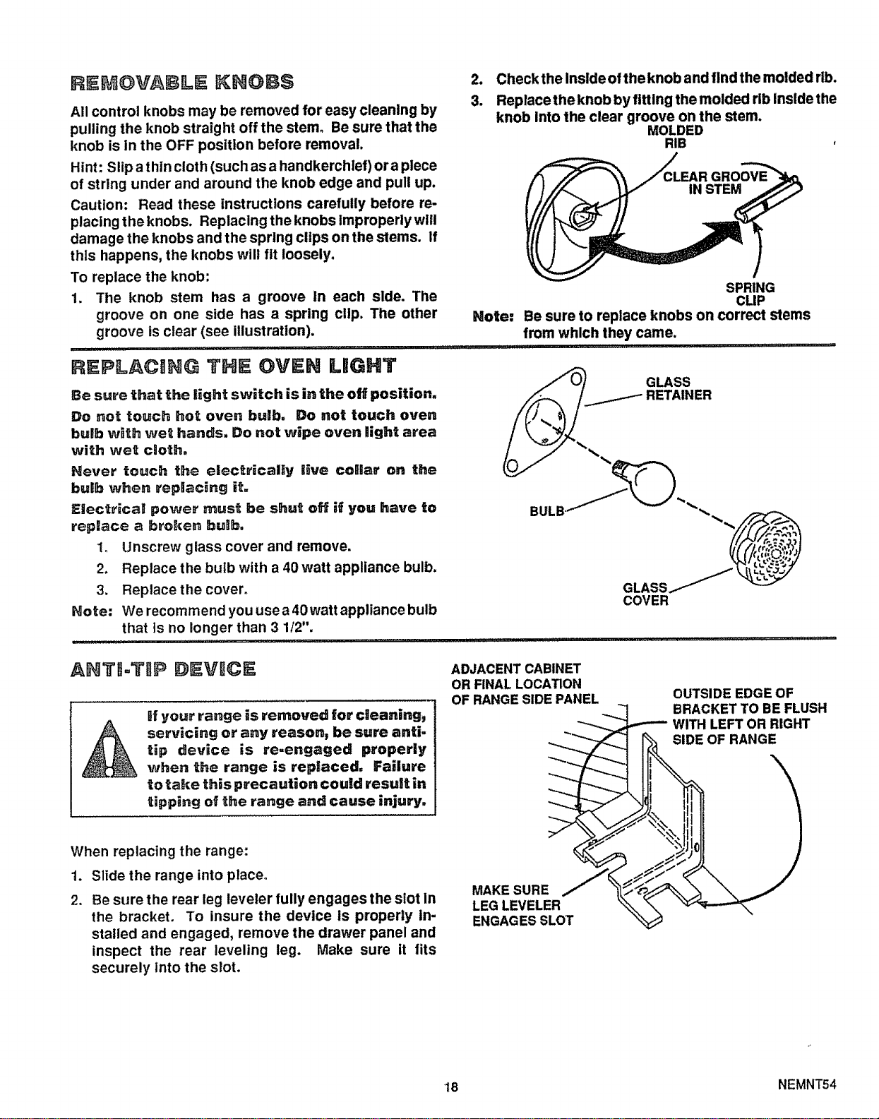
3.
Check the Inside ofthe knob and find the molded rib.
Replace the knob by fitting the molded rib Inside the
knob Into the clear groove on the stem.
MOLDED
RIB
Note:
SPRING
CLIP
Be sure to replace knobs on correct stems
from which they came.
REPLACING THE OVEN LIGHT
Be sure that the light switch is in the off position,
Do not touch hot oven bulb, Do not touch oven
buJb with wet hands. Do not wipe oven light area
with wet cloth,
Never touch the electrically live coOIlar on the
bulb when replacing it,
Electrical power must be shut off if you have to
repBace a broken bulb.
1. Unscrew glass cover and remove.
2. Replace the bulb with a 40 watt appliance bulb.
3. Replace the cover.
Note: We recomm end you use a 40 watt appliance bulb
that is no longer than 3 1/2".
....................... i................
GLASS
RETAINER
,,lip ,,IU, J, ,! ,i ,M, .......................
AHTI=TI]P DEVICE
lif your range _s removed for cleaning,
servicing or any reason, be sure anti-
tip device is re-engaged properly
when the range is replaced, Failure
to take this precaution could result in
tipping of _he range and cause injury,
When replacing the range:
1. Slide the range into place.
2. Be sure the rear leg leveler fully engagesthe slot in
the bracket. To insure the device is properly In-
stalled and engaged, remove the drawer panel and
inspect the rear leveling leg. Make sure it fits
securely into the slot.
ADJACENT CABINET
OR FINAL LOCATION
OF RANGESIDE PANEL
MAKE SURE
LEG LEVELER
ENGAGES SLOT
OUTSIDE EDGE OF
BRACKET TO BE FLUSH
•-,-'-- WITH LEFT OR RIGHT
OF RANGE
18 NEMNT54
Loading ...
Loading ...
Loading ...